1
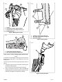
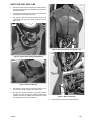
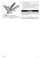
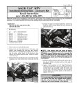
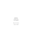
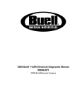
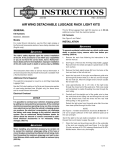
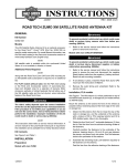
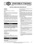
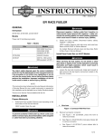
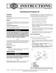
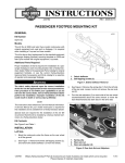
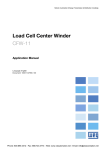
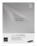
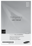
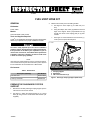
-J04820
REV. 2008-10-23
FUEL VENT HOSE KIT
3.
GENERAL
Kit Number
P1032.1AMA
Measure and center punch the drilling location.
a.
See Figure 2. Set a caliper (1) to 0.500 inch (12.7
mm).
b.
Using the caliper, draw a line (2) parallel to the back
edge of the support. draw a perpendicular line (3)
through the center of the footpeg pivot pin (4) hole
location.
c.
See Figure 3. At the intersection of the two lines (1),
center punch a spot for the drill point.
Models
This kit fits 2008 1125R models.
Tools and Supplies Required
Loctite® 271 Threadlocker and Sealant - Red (H-D Part Number
99671-97) is required for the proper installation of this kit.
is05823
The rider's safety depends upon the correct installation
of this kit. Use the appropriate service manual procedures.
If the procedure is not within your capabilities or you do
not have the correct tools, have a Buell dealer perform the
installation. Improper installation of this kit could result
in death or serious injury. (00334a)
1
3
NOTE
2
This instruction sheet references service manual information.
A service manual for this year and model motorcycle is required
for this installation and is available from a Buell dealer.
Kit Contents
Table 1. Kit Contents
Description (Quantity)
Part Number
Fuel vent hose
P0032.2AMA
P-clamp, cushioned
Q0300.4A8
1. Footpeg support
2. Wood base
3. OE screw and washer (2)
Figure 1. Passenger Footpeg Support (Back View)
PREPARE THE PASSENGER FOOTPEG
SUPPORT
1.
Remove the left-side passenger footpeg support per the
instructions in the service manual.
2.
See Figure 1. Attach the footpeg support (1) to a wood
base (2) using common wood screws and washers (not
supplied).
-J04820
1 of 4
is05826
is05824
1
4
3
2
1.
2.
3.
4.
1
Caliper
Line parallel to back edge of support
Perpendicular line through center of pin
Footpeg pivot pin
3
2
Figure 2. Marking Drill Location
is05825
1
2
1. Footpeg pivot pin hole (reference)
2. Drill angle approximately 37 degrees
3. Pilot hole location
Figure 4. Drilling Angle
is05827
1. Center punch spot for drill point
2. Drill must not penetrate shaded area
Figure 3. Hole Location (Footpeg Support, Bottom View)
NOTE
To maintain structural integrity of the support, the drill must not
penetrate the casting web (2, the shaded area) under the
footpeg mount.
The hole should be drilled at the approximate angle shown in
Figure 4.
4.
See Figure 5. Drill a 1/8 inch (3 mm) pilot hole through the
passenger footpeg support.
Drill a 17/64 inch (7 mm) hole through the pilot hole.
5.
Apply a few drops of Loctite 271 - Red to the clean OE
footpeg support screw threads. Install the support with the
fasteners, and tighten to 25-28 ft-lbs (34-38 Nm).
Figure 5. Drilling Pilot Hole
-J04820
2 of 4
ROUTE THE FUEL VENT LINE
1.
Remove the seat from the vehicle per the instructions in
the service manual. Remove the intake cover per service
manual instructions.
2.
See Figure 6. Pull the fuel vent hose out from the engine
compartment and off of the vent valve.
3.
See Figure 7. Push the soft line vent hose over the vent
valve fitting, and route the soft line vent hose over the
airbox cover.
is05830
is05828
Figure 8. New Hose Routing over Airbox Cover
is05831
Figure 6. Original Hose Routing (2008 Models)
is05829
Figure 7. New Hose Routing
4.
See Figure 8. Press the soft vent hose firmly into the
groove along the entire length of the airbox cover.
5.
See Figure 9. Route the hard line vent under the cross
member and down through the subframe between the
subframe and the pan splitting the tail lamp/turn signal
wire leads from the fuse center harness.
Figure 9. Hard Line Routing
6.
-J04820
Push the soft line vent hose over the hard line.
3 of 4
is05832
7.
See Figure 10. Push the vent line (1) through the drilled
hole in the footpeg support.
8.
Remove the upper fastener (3) attaching the passenger
heel guard to the left-side passenger footpeg support.
Fit the P-clamp (cushioned oil line clamp) (2) and tighten
the fastener to 57-63 in-lbs (6.4-7.1 Nm).
3
9.
Install the intake cover and seat per service manual
instructions.
2
1
1. Vent line
2. P-clamp
3. Passenger heel guard upper fastener
Figure 10. Hose Routing through Footpeg Support and
P-Clamp
-J04820
After installing seat, pull upward on seat to be sure it is
locked in position. While riding, a loose seat can shift
causing loss of control, which could result in death or
serious injury. (00070b)
NOTE
Installation of the new vent line assembly will reduce fuel vapor
condensation. However, variable temperature conditions may
lead to occasional condensation discharge from the vent line.
4 of 4