1
FILE NO.
SUPPLEMENTOF
SERVICE MANUAL
Microwave Oven
EM-X471 s
EM.x471 Ys
EM-X471 us
EM-X471 Ss
EM-x471 BS
(Australia/New
Zealand)
.
PRODUCT
NO.
EM-X471
s
43745047
EM-X471
Ys
43745048
I EM-X471
us
I EM-X471SS
I
Foreword
L
CODE
MODEL
NO.
/
43745049
I
I
43745050
I
1
EM-X471
43745054
BS
See the Service Manual ofEM-X670S(SM-860177)
except the items described in this Service Manual.
Read this manual carefully, especially precaution on microwave energy, and follow the procedure
Careless servicing and testing may expose yourself to the microwave energy leakage.
strictly.
PRECAUTIONS
PRECAUTIONS TO BE OBSERVED BEFORE AND DURING SERVICING
EXCESSIVE MICROWAVE ENERGY
(a)
TO AVOID POSSIBLE
EXPOSURE
TO
Do not operate or allow the oven to be operated with the door open.
(b) Make the following safety checks on all ovens to be serviced before activating the magnetron
source, and make repairs as necessary:
or other microwave
(1) Interlock operation, (2) proper door closing, (3) seal and sealing surfaces (arcing, wear, and other damage),
(4) damage to or loosening of hinges and latches, (5) evidence of dropping or abuse.
(c)
Before turning on microwave power for any service test or inspection within the microwave generating compartments,
check the magnetron, wave guide or transmission line, and cavity for proper alignment, integrity, and connections.
(d) Any defective or misadjusted components in the interlock, monitor, door seal, and microwave generation and transmission systems shall be repaired, replaced, or adjusted by procedures described in this manual before the oven is
released to the owner.
REFERENCE
NO. SS -860264
- TABLE OF CONTENTS
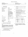
Specifications
Power Output
Circuit
Diagram
. . . . . . . . . . . . . . . . . . . . . . . . . . . . .
Measurement
. . . . . . . . . . . . . . . . . .
1
1
Test Procedures
. . . . . . . . . . . . . . . . . . . . . . . . . . . .
2
Overall
Rated Power Consumption
1500 w.
Microwave
1000 w.
Output.
.
Exploded
(c)
SPECIFICATIONS
1.
-
...
(D)
. . . .
3-4
5-10
. . . . . . . . . . . . . . . .
11
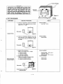
1. Set cooking time to two (2) minutes. (“2 00 appears
in display)
1. Take out the two bowls at once.
2. Stir both water with thermometer and measure the
water temperature rise respectively.
Safety Devices . . . . . . . . . . . . Temp. Fuse, Open
at 167CforCavity.
Thermal Protector, Open
at 122’’C for Magnetron.
Fuse (Cartridge Type 8A)
Primary Interlock Switch.
Door Sensing Switch and
Relay 2.
Interlock Monitor Switch.
(E)
1. Get temperature rise by calculation the difference
(water temperature after cooking minus initial
temperature) in each bowl.
2. Then calculate average value(t) of both temperature
rise in degrees centigrade.
3. Then work out;
Power Output (watt) = 70x
Timer . . . . . . . . . . . . . . . . . . . Electronic Digital, up to
99min, 99 sec.
.
Diagram
.
. . . . . . . . . .
240V,50HZ.
Rated Current . . . . . . . . . . . . . 6.6 Amp.
Overall Dimensions . . . . .
Circuit
List..
2. Touch START key and operate oven for exactly two
(2) minutes.
Frequency . . . . . . . . . . . . . . . . 2450MHz*50MHz.
Power Supply . . . . . . . . . . . . . 230-
. . . . . . . . . . . . . .
View and Parts
At
Where At is an Average Temperature
centigrade.
525 (W) X 425 (D) X 289 (H)
mm.
(F)
Power Output shall be in the following
Rise m degrees
range:
Oven Cavity Size . . . . . . . . . . 351 (W) X371( D) X208(H)
mm.
Turntable
Diameter
.......
Average
Temperature
275 mm.
Effective Capacity of
Oven Cavity . . . . . . . . . . . . . . 28 liters.
Minimum
11.2°C
Net Weight . . . . . . . . . . . . . . . Approx. 17 Kg,
Maximum
13.T’C
POWER
2.
OUTPUT
(G)
The Power Output specification
1000 Won this model is
measured with IEC measurement.
The Power Output is
measured with two (2) liters water is equivalent to 1000W in
measurement with IEC, when measured with the following
power output.
1. Fill two test bowls with each 1 liter water respectively.
2. Use accurate thermometer and measure each
water temperature respectively
(B)
I
I
Microwave
Power Output
784 W
I
I
959 w
MEASUREMENT
NOTE
(A)
Rise
Place the two bowls on glass turntable.
–l-
Power Output will be influenced by line voltage of
power supply. Consequently, correct power output
must be measured within 240V AC * 2 volt while unit
is operating.
.
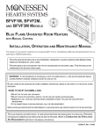
3.
CIRCUIT
N@L
DIAGRAM
W,.coq
--
pvvmccm
~
-1-WLM J -
,–
IN
I
I
I
I
r4@?~c3i‘L
——— —
-.
CAVITY LIGHT
w
t
INTERLOCK
SWITCH
,-?
w
w
Y
MONITOR
INTERLOCK
PRIMARY
SWITCH
Y
lid
BLOWER MOTOR
w
‘c@
:OM
Y
BK
GEAR MOTOR
(——————
I
1
— ———
HIGH
VOLTAGE TRANSFORMER
~__———
— — ——
—
—
L-&‘i
1
[ CONNECTOR
S1
F!!+!y:
15
@l_’
2
J
I
1’-’
I‘
I
L
l!!l
CONNECTOR
S102
‘
l!
●
L———
a
t STEP DOWN
I TRANSFORMER
L————
————
.;
———
———
—
——
—
7V
—.
I
——J
20 KVD~
FUSE DIODE
&
4.2 KVDC
L———
NO@
DOOR
SENSING
SWITCH
1
CONNECTOR
Slol
❑
TOUCH
KEY
BOARD
CIRCUIT
BOARD
L————J
DIODE
MAGNETRON
CAPACITOR
RESISTOR
10 MEG-OHM
1.10 Uf
2.5 KV
m
—— —— ——
.J
UK
WIRING
‘HE
:
“GN
THE SIGN
COLOUR
BK : BLACK
❑
Parts marked with this sign are supplied with
High Voltage exceeding 250V,
o
Parts marked with this sign have special
characteristics
important for microwave
leakage. When replacing any of these parts
use only manufacturer’s
specified parts.
~
–2-
I
I
Figure 1
NOTES
-—
●
❑
,0 COM
—1
a
I
In
1
RELAY 1
●
w
I
f-
13
11
%
n
$----
w
MAGNETRON
THERMAL PROTECTOR
OPEN : 122*5°C
CAVITY TEMP FUSE
OPEN : 167~°C
BL
W
o
R
Y
:
:
:
:
:
BLUE
WHITE
ORANGE
RED
YELLOW
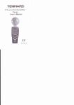
4. TEST
PROCEDURES
—
-3-
/4
CAUTION
-DISCONNECT
THE POWER SUPPLY CORD FROM
THE WALL OUTLET WHENEVER REMOVING THE
CABINET FROM THE UNIT. PROCEED WITH THE
TESTS ONLY A17ER DISCHARGING
THE HIGH
VOLTAGE CAPACITOR AND REMOVING THE LEAD
WIRES FROM THE PRIMARY WINDING OF THE
HIGH VOLTAGE TRANSFORMER.
(SEE FIGURE 3)
Secondary
Windings
Filament Windings
/
re 3
4
A, TEST PROCEDURES
t-
-4-
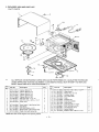
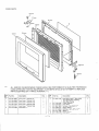
5. EXPLODED
CAVITY
***
VIEW
AND
PART
ALL SERVICE
ON MICROWAVE
USING APPROVED
PARTS IDENTIFIED
:ey
kL-
LIST
PARTS
Part No.
OVENS
SHOULD
BE PERFORMED
TESTING
EQUIPMENT.
CUSTOMERS
BY A TRIPLE ASTERISK
(***).
Description
‘ey Pari
2’ty.
1
6172149172
Cabinet, EM-X471 S
1
6172242262
Cabinet, EM-X471 YS
1
6172242125
Cabinet, EM-X471 US
1
1
2
3
4
5
6
7
8
9
10
6172244082
6172149998
4110825201
411 1606007
6172250724
Cabinet, EM-X471 SS
Cabinet, EM-X471 BS
SCR TPG TRS 4 X 10 Z1
SCR TPG TRS + SRT 4 X 10 Z1
Power Cord
1
8
4
1
6172049366
6171512458
4110105808
6171385601
6172216089
Oven Cavi~”
(Not Service Part)
Gear Motor
SCR EVR PAN 4 X 10 Z1
Bottom Plate’’’(Not
Service Part)
Plastic Foot with Canoe Clip
1
1
2
1
4
SHOULD
10.
11
12
13
14
15
16
17
18
19
20
21
22
23
24
1
1
1
1
40TE :Also order Circuit Diagram when replacing Cabinet
–5-
No.
411011 0802
6171806137
4110892500
6171208481
6171444476
6172049489
6170735889
6172049403
6171621938
4110691707
4110066604
6172000381
6170805315
411 1606106
BY A QUALIFIED
NOT ATTEMPT
TECHNICIAN
TO REPLACE
Description
Bolt Hex+ SW+ W5x14Zl=*’
Hinge Lower’”
Washer F5 x 10 x 0.8
Insulation Sheet
Turn Table Shaft
Roller
Rotating Tray
Antenna Complete
Cavity Cover
SCR TPG TRS 4 X 6 DA
SCR TPG PAN 3 X 6 Z1
Thermal Fuse 167°C
Special Washer
SCR S-TTRS + SRT 4 X 10 Z1
Q’ty.
2
1
1
1
1
1
1
1
1
1
2
1
1
2
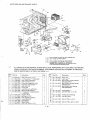
SWITCHES
AND
MICROWAVE
PARTS
)
31
Parts marked with this sign are supplied
high voltage exceeding
250V.
with
Parts marked with this sign have special
characteristics
important for microwave
leakage. When replacing any of these parts use
only manufacturers
specified parta.
***
ALL SERVICE
ON MICROWAVE
USING APPROVED
PARTS IDENTIFIED
‘y
o.
L
OVENS
Part No.
Description
4110825201
SCR TPG TRS 4 X 10 Z1
H. V.Transformer,’”’YS-X670
SAP
Stay, Cavity & Magnetron
SCR TPG PAN 3 X 6 Z1
Thermostat, Magnetron 122°C
Magnetron, 2M219H(B)A-’”
Fuse, 250V 8A
Power PCB
Lead Wire Ass’y, with Diode
Space Partition (Blower)
H. V.Capacitor including Resistor,
1.lOuf 2.5KV.
Capacitor Band
Bolt Hex 4 x 10 Z1
Duct, Magnetron Exhaust
Lamp, 240V 25W
Lamp Socket
Blower Motor
SCR TPG TRS 4 X 10 Z1
1
2
3
4
5
6
7
8
9
10
11
6172080260
6171998283
411 0066604
6171241235
4150026101
4230227503
6172133416
6172258553
6171621990
6172129013
12
13
14
15
16
17
18
6171822373
411011 5609
6171984996
6171103618
6171241280
6171670592
4110825201
SHOULD
BE PERFORMED
TESTING
EQUIPMENT.
CUSTOMERS
BY A TRIPLE ASTERISK
(***).
SHOULD
‘y
GYty.
6
Q’ty.
Description
19
20
21
6171968507
6171241181
617221 4078
1
1
1
22
617221
4061
23
617221
4078
Blower Fan
Latch Lever ‘*’
Micro Switch, Primary Interlock
AM51630C53F2””*
Micro Switch, Interlock Monitor
AM50620C53*”
Micro Switch, Door Sensing
AM51630C53F2’*”
6171241174
411 1025907
Lever Stopper *“”
SCR ETG TRS 4 X 10 N2
1
2
6171173505
6171243796
Harness (Door Sensing)
Lead Wire Ass’y
1
1
4110014704
SCR S-T PAN 4 X 10 Z1
1
411 1606106
SCR S-T TRS + SRT 4 X 10 Z1
1
24
25
26
27
28
29
30
31
32
33
1
4
1
1
1
1
2
TECHNICIAN
TO REPLACE
Parl No.
o.
8
1
1
1
1
1
1
1
1
1
1
BY A QUALIFIED
NOT ATTEMPT
1
1
DOOR
PARTS
1 ***
\
\
\
,IF
.
,1O***
\
‘
9***
/’
!
***
ALL SERVICE
USING
PARTS
ON MICROWAVE
APPROVED
IDENTIFIED
TESTING
OVENS
SHOULD
EQUIPMENT.
BY A TRIPLE
ASTERISK
Description
Q’ty.
:ey
do.
1
6172076294
Door Cover ●’”EM-X471S
1
1
6172242286
Door Cover ** ’E M-X471YS
1
1
6172242149
Door Cover ‘“*EM-X471
1
6172244105
Door Cover “’EM-X471SS
1
2
6172107271
6172107592
Door Cover **’EM-X471
Door Panel ‘“
1
1
BS
SHOULD
BY A QUALIFIED
NOT ATTEMPT
TECHNICIAN
TO REPLACE
(-).
I
us
BE PERFORMED
CUSTOMERS
1
1
I
-7-
Part No.
Description
3
6172057163
4
5
6
7
8
9
10
6171240948
6171240931
4110541903
6171806151
4110110802
617101 1494
6171792478
Door Main Frame’”
(Also order
-Door Sheet when replacing
-Door Main Frame)
Choke Dielectric””
Door Sheet
Nut Hex + Flg WISRT 5’”*
Hinge, Upper***
Bolt Hex+ SW+ W5x14°
Spring ‘“
Door Latch ‘“
Q’ty.
1
1
1
2
1
2
1
1
—
CONTROL
PANEL
PARTS
5
fj ,,.
2***
\
1***
\
1
3***
\
\
9***
***
:ey
&
ALL SERVICE
ON MICROWAVE
USING
APPROVED
PARTS
IDENTIFIED
TESTING
OVENS
EQUIPMENT.
BY A TRIPLE
Part No,
Description
SHOULD
BE PERFORMED
CUSTOMERS
ASTERISK
SHOULD
BYA
QUALIFIED
NOT ATTEMPT
TECHNICIAN
TO REPLACE
(***).
Yty.
:ey
10.
Part No.
Description
Q’ty.
6172256054
Control Sheer””
EM-X471 S
1
4
6172070377
Control Base’””
1
1
6172258423
Control SheeV”
EM-X471YS
1
6172258430
Control Sheet””’
EM-X471 US
1
EM-X471SS
1
411 1606205
6172227016
411 1295805
6170809559
6172070353
6172242316
6172242187
6172244136
6172107288
SCR TPG TRS + SRT 4 X 10 Z1
Power & Control Circuit Board***
SCR TPG BIN 3 X 10 Z1
Spring, Door Release Lever’”
Door Release Lever”””EM-X471 S
Door Release Lever’* *EM-X471 YS
Door Release Lever* ”’EM-X471 US
Door Release Lever’’’EM-X471
SS
Door Release Lever* ’*EM-X471 BS
1
1
5
6
7
8
9
9
9
9
9
1
1
1
2
3
3
3
3
3
L
6172258447
Control Sheet’”
6172259963
6172248189
Control Sheet’** EM-X471 BS
Touch Key Board’**
1
1
6172076317
Control Frame*”’
EM-X471 S
1
6172242323
Control Frame***
EM-X471 YS
1
6172242194
Control Frame’**
EM-X471 US
1
6172244143
Control Frame*”’
EM-X471 SS
1
6172107301
Control Frame”*
EM-X471 BS
1
eet and vi__ ver: [
NOTE : Also order Touch Key Board when replacing Control
<ey
10.
PRINTED MATTER (Items Not Illustrated)
Part No.
6171987324
6172248219
6172129006
6172248202
6172251943
Description
lQ’ty.
I
t
1
Cook Book
Operating
1
2
1
1
1
1
1
1
1
Instructions
1
Circuit Diagram
Carton
Box Comp.
EM-X471
S
1
Carton
Box Comp.
EM-X471
YS
1
–8
Part No,
Description
6172251998
6172252049
6172259956
6172248158
6172251899
6172251950
6172252001
6172259871
Carton
Carton
Name
Name
Name
Name
Name
l’ty.
Carton Box Comp.
Box
Box
Plate
Plate
Plate
Plate
Plate
EM-X471
Comp. EM-X471
Comp. EM-X471
EM-X471 S
EM-X471 YS
EM-X471 US
EM-X471 SS
EM-X471 BS
US
SS
BS
1
1
1
1
1
1
1
1
1
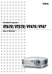
CONTROL
CIRCUIT
(Part NO. 617222
n
BOARD
7016)
13TI r————————————
■ l-r
—————~
TP-6
TP-5
TP-3
,J-,~
l\
I
\
1.1
0
_ cd
Cn
TP-I
4
I (--TWI
I’5%3(
I “ ‘“’’”” ((
-D-
TP-2
TP-4
J107
o
TnFin
~
4
=
u
-u’
(J51
1
#j
‘
I
013/J
K&C
L59WO~ o
-9-
GROUND
108 ~;
-.
f
CONTROL
CIRCUIT
(Part NO. 617222
Key No.
BOARD
7016)
Order Pari No.
Description
Q’ty
Order Part No.1
Description
R101, 107,
114,123-127
4010125639
Carbon, lK ohms
+ -5%, J14W.
R
R15, 102,
108,109,116
4010126953
Carbon, 10Kohms
+ -5%, 114W.
5
R126, 130, 1
4010126056
Carbon, 100Kohms
+ -5%, J14VV.
3
Key No.
I
I
Q’ty
L
INTEGRATED CIRCUIT.
Icll
4094414606
RESISTORS
IC LM8796C-360SP
1
TRANSISTORS.
4050043010
2SA564A-Q-TP
2
Q101
4050824619
DTA123YS-TP
1
QI02, 105,
107
4050001812
DTA143XS-TP
3
R16, 52,
55, 56
401 0136338
Carbon, 12Kohms
+ -5%, 114W.
4
QI04
4050354819
2SC1685-Q-TP
1
R13,14
4010162555
Carbon, 220 ohms
+ -5%, l/4w.
2
Q106
4050003113
DTC114ES-TP
1
RI05
4010163750
4050005612
DTC143XS-TP
1
Carbon, 2.2K ohms
+ -5%, 714W,
1
Q103
R104,1O6
4010164757
Carbon, 22K ohms
+ -5%, I14W.
2
Rlll,
4010169653
Carbon, 27 ohms
+ -5%, ~14w.
2
R115
4010171735
Carbon, 2.7K ohms
+ -5%, 114W.
1
R11O
401 0182751
Carbon, 330 ohms
+ -5%, 114W,
1
R113
4010183738
Carbon, 3.3K ohms
1
Qll,
12
DIODES.
Dll,
12
4070120220
1N4002-TP
2
D101-107
4070124426
1SS133-TP
7
ZD14
4070514415
GZS13Y-AT1
1
ZD1l
4070570510
RD5.6ESB3
1
ZD12
4071606713
RD27ESB1
1
ZD13,101
4071322316
HZS3.9NB2
2
+ -5%, ~14w.
CAPACITORS
C102
4030024728
Ceramic,O.lmfd,
+-5”A, 25V,
1
C103, 104
4030696355
Ceramic, O.Olmfd,
+-5%, 50V,
2
Clol
4031478837
Electrolytic,l mfd,
+-20%, 50V.
1
Cll
4031527327
Electrolytic, 100mfd,
+-20%, 35V.
1
C13
4031478629
Electrolytic,47mfd,
+-20%, 1Ov.
1
Electrolytic,470mfd,
+-20%, 25V.
1
C12
4031608729
112
R117-122,
11
4010201957
Carbon, 4.7K ohms
+ -5%, ~14w.
7
R103,53
4010202835
Carbon, 47K Ohms
+ -5%, ~14W.
2
4010212953
Carbon, 5.6K ohms
+ -5%, l/4w.
1
BZ1
4200006800
Buzzer, PKM22EPT-2001
1
VST1
4071185505
Varistor ENC 471D-IOA.
1
DT1
6172209784
Dispfay Tube.
1
RL1
6171379358
Relay, OJE-SH-112LM.
1
RL2
6171410549
Relay, DEC DU12D1-l PR.
1
RS1
6171263372
Ceramic Oscillator
1
S1
6171694109
Connector.
1
Slol
6171268959
Connector,l 1P
1
S201
6170024396
Connector,3P,Male.
1
S102
6171111392
Connector, 2/3P, Mafe.
1
PT1
6171712155
Step-Down Transformer,
PD5TK-S150
1
2
6170794107
Spacer
1
JI-6
6170794299
Jumper.
6
J101-108
6170794237
Jumper.
8
R12
MISCELLANEOUS.
-10”
—-- --I
I
I
I
---
__— ——- ___ ___ _=
-5V
Sloz
W3LEx
I
AC230VW240V
50Hz
---
RIM
342) P
I
-
OPEN
70
OPEN
I
OWN
&
P43
SENSIN13
I
P42
I
2713
Px
I
P?
R112
P*
I
P7,
~
Px
I
-.
Pa
2
I
INTERLOCK CIRCUIT
P44
a
P82 1AM
I
I
I
I
k
mm
“WIT
1= n
,,
D
MAIN
,
fH~;L
K&&
P45
w-,%
w
.
.
I
r --
h
r
L__
47K
-
----
--
-
-
-
-
—
—
_
_
_
_
_
_
__
_
_
J
47K
;
mx&
I
I
I
I
,x
R,2,U
47.
I ‘“
I
(1)
(2)
0
(3)
6
5
(4)
yg:
(5)
::,::;
u~
GL
I
47s
P.
s:
(6)
E:;R E
1
RIB.,,
!5
lK
I
I
1
I
I
2
I
I
3
nu
a’
UJ:
, 1111
!
8
u(!
9
]fl?&
s7ART
E%
“%::,
=--.OVF
m
(PD)
DISPLAY
TUBE
I
“El
Lmd.4-Lv ‘
.——————-----
F’WAN1
Priwn!
$?11
4,7K
%=3=
R56
Rt3..,2x-
m
m.”’
:;;
,,w
Ri
*
-w
WA
m,
“,..13
I_
_b--—--w
———-.
I
___
I
::
12K
?~
Xlb
1
?%
—.—
———
0
‘ TIME BASE
! c, Rc”,T
VF
l------------———
—
,
mv
--l
h
-w
Vcc
93
R?,,
-------
23
31
,Dm.z
:
l-------
w!
VRFF
~lf
R15
~ou,
P4MNT0
VF
22un
----------WWC::CSUWVLY
12K
R53 47K
P41,1NT!
T
______
u
FW4AN4
-2ZY
R16
———
(PO)PO
(PO]m
(PO]m
(m) Fo
(PO)Pa
(PO,m
[PO,m
Q12
g:g
IN4CU2
—
OPEN
w
P.?4
011
JiiJlig
1-- . . . . . .
.1
PT$ PD5TI-SIW
.——
———
WEN
+
-5V
“1,
I
——.
~
~,,m
,
m
:
v,
P,
[PO)
P4,
P5,
(Pu)
&
$)
.
1111
r
10
-Lo
[PO) Pt
P52 (P“)
P27
,;
.
P?’
:g
I
(
C12
PI,
[m)
ZD? 1
RD5.3ES6=3
+
~
Pa
[m
4
m 1
1N402
C1l
;%
______
OT 1
25
(P”,
J____________
––––--––––--.
●
(w)
(P”,
3
I
———-,
---------- .
WAN
,:
i %5
11
- +’$4
,:
~ m
R122
I
J
—_____
(Po)
1
-
I
MAGNETRC+.
J
P4$T
II
, ----------
321
>
t‘;
I
__:
—---
(PO) P*
,
RI13
33K
; KEY
BOARD
I CIRCUITRW7
II
—
Iw
I
I
I
10
I
I
I
II
II
II
II
--
(Po) P2
(PD)
P47n3
‘ BUZZER
I DRIVE
, CIRCUIT
L .:
----——
‘
(PD) P,
E
●
)7
[PO) P2
1
~
●
{PO) P??
“m
,N,,m
w.m.mlcq
r— -—--
CO
I
I
I
Avs!
32
4MHz
3
-5.
_____
CIRCUIT
----
---
I
I
I