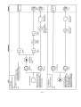
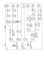
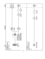
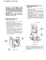
1
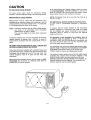
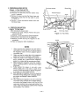
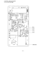
SUPPLEMENT OF
SERVICE MANUAL
Microwave Oven
EM-C160US
File No:
SERVICE MANUAL SUPPLEMENT
SERVICE MANUAL
Microwave Oven
for Model EM-S100
EM-S100
Microwave Oven
PRODUCT CODE NO. 437-453-00
See the Service Manual of EM-C180US(SM-640179)
except the items described in this Service Manual.
Product Code No: 437 436 05
CAUTION
WARNING TO SERVICE TECHNICIANS
CAUTION
PRECAUTIONS
TO
BE
OBSERVED
BEFORE AND DURING
WARNING TO SERVICE TECHNICIANS
SERVICING
TO AVOID
POSSIBLE
TO
PRECAUTIONS
TO BE
OBSERVEDEXPOSURE
BEFORE AND DURING
SERVICING TO
AVOID POSSIBLE
EXPOSURE TO
EXCESSIVE
MICROWAVE
ENERGY
(a) Do not operate or allow the oven
to be operatedMICROWAVE
with the door open. ENERGY
EXCESSIVE
(b) Make the following safety checks on all ovens to be serviced before activating the magnetron or other
(a)
Do not operate
allow
the oven
to beasoperated
with the door open.
microwave
source,orand
make
repairs
necessary:
(1)Interlock
operation,
(2)
proper
door
closing,
(3)
and sealing
surfacesthe
(arcing,
wear,orand
(b) Make the following safety checks on all ovens to beseal
serviced
before activating
magnetron
otherother
microwave
damage),
(4)
damage
to
or
loosening
of
hinges
and
latches,
(5)
evidence
of
dropping
or
abuse.
source, and make repairs as necessary:
(c) Before
microwave
powerdoor
for any
service
testand
or sealing
inspection
within
the microwave
generating
(1)turning
Interlockon
operation,
(2) proper
closing,
(3) seal
surfaces
(arcing,
wear, and other
damage),
(4) damage check
to or loosening
of hinges wave
and latches,
(5) transmission
evidence of dropping
or abuse.
compartments,
the magnetron,
guide or
line, and
cavity for proper alignment,
integrity, and connections.
(c) Before turning on microwave power for any service test or inspection within the microwave generating compartments,
(d) Any defective
or misadjusted
in theline,
interlock,
monitor,
door
seal, and
microwave
generation
check the magnetron,
wave components
guide transmission
and cavity
for proper
alignment,
integrity,
and connections.
and transmission systems shall be repaired, replaced, or adjusted by procedures described in this manual
(d) Any
misadjusted
components
before
thedefective
oven isorreleased
to the
owner. in the interlock, monitor, door seal, and microwave generation and transmis-sion systems
shall be
repaired,
replaced,
or adjusted
procedures
described in this
manual before
(e)(i) A microwave
leakage
check
to verify
compliance
withbythe
Federal performance
standard
shouldthe
beoven is
released
the owner.
performed
ontoeach
oven prior to release to the owner. (For U.S.A)
(e)(ii)(e)
A(i)microwave
leakage
verifycompliance
compliance
Canadian
Regulation,
WELFARE,
A microwave
leakagecheck
check to
to verify
withwith
the the
Federal
performance
standardHEALTH
should beAND
performed
on each
SOR/79-920
should
be
performed
on
each
oven
prior
to
release
to
the
owner.
(For
CANADA)
oven prior to release to the owner. For U.S.A.
(e)(ii) A microwave leakage check to verify compliance with the Canadian Regulation, HEALTH
AND WELFARE,
REFERENCE
NO.SM-640180
SOR/79-920 should be performed on each oven prior to release to the owner. For CANADA
FORM # EM-S100 (02/05)
REFERENCE NO. SM - 860235
-- i --
-- 1 --
2. SPECIFICATIONS
4. PRECAUTIONS AND REPAIR SERVICE TIPS
PRELIMINARY
Rated Power Consumption . . .
Microwave Output . . . . . . . . . .
Frequency . . . . . . . . . . . . . . . .
Power Supply . . . . . . . . . . . . .
Rated Current . . . . . . . . . . . . .
Safety Devices . . . . . . . . . . . .
Timer . . . . . . . . . . . . . . . . . . .
Overall Dimensions . . . . . . . . .
Oven Cavity Size . . . . . . . . . . .
1600W
1000W
2,450MHz±50MHz
120V, 60Hz
12.9Amp
Thermal Fuse open
at 167oC for Cavity
Thermal Protector open
at 122oC for Magnetron
Fuse (Cartridge Type 15A)
Primary Interlock Switch
Door Sensing Switch and
Relay 2
Interlock Monitor Switch
Electronic Digital, up to
99 min. 99 sec.
525(W) x 420(D) x 283(H)
mm
350(W) x 371(D) x 208(H)
mm
340mm
A. SINCE NEARLY 2,000 VOLTS EXISTS IN SOME
CIRCUITS OF THIS MICROWAVE OVEN, REPAIRS
SHOULD BE CARRIED OUT WITH GREAT CARE.
B. TO AVOID POSSIBLE EXPOSURE TO MICROWAVE
ENERGY LEAKAGE, THE FOLLOWING PRECAUTIONS MUST BE TAKEN BEFORE SERVICING
Turn Table Diameter . . . . . . . .
Effective Capacity of
Oven Cavity . . . . . . . . . . . . . . 26 liters
Net Weight . . . . . . . . . . . . . . . Approx. 16.5kg
3. POWER OUTPUT MEASUREMENT
NOTE
The power output specification, 1000 W on this model is
measured with IEC measurement. The power output is
measured with two (2) liters water is equivalent
to 1000 W in measurement with IEC, when measured with
the following power output.
(1) Fill two beakers (glass or plastic) with each one liter of
tap water (about 20oC) and measure the water temperature. (Use a thermometer with a 1/10 degree gauge).
(2) Place the beakers side by side in the centre of the glass
tray.
(3) Close the door, set the “TIME” for two minutes. (“2 00”
in the display window.) Touch the “START” key and heat
the water exactly for two minutes.
(4) Take the beakers out, immediately stir the water and
measure the water temperature respectively.
(5) Calculate the temperature rise of water in each beaker.
Then calculate the average value of two temperature
rises.
Output power can be calculated by the equation;
Power Output (W) = 70 x Dt
Where Dt is an average temperature rise in degrees
Centigrade.
(6) Output shall be in the following range :
AverageTemperature Rise Power Output
Minimum
10.9oC
763W
Maximum
14.0oC
980W
Power Output is affected by the line voltage under load.
(7) For correct Power Output measurement, the line voltage
under load must be 120± 2volts.
-- 2 --
(1) Before the power is applied :
(a) Open and close door several times to make sure
the primary interlock switch, the interlock monitor
switch and the door sensing switch operate properly. (Listen for the clicking sound from the switches.)
Make sure the interlock monitor switch closes after
the primary interlock switch is opens when the door
is opened.
(See pages 1 and 6)
(b) Make sure the perforated screen and the choke
dielectric of the door are correctly mounted.
(2) After the power is applied :
(a) Open and close the door to see if the interlock
mechanism operates properly.
(b) Check microwave energy leakage with a leakage
detector and confirm the energy leakage is below 5
mW/cm2.
(3) Do not operate the unit until it is completely
repaired, if any of the following conditions exists:
(a) Door does not close firmly against the cavity front.
(b) The hinge is broken.
(c) The choke dielectric or the door seal is damaged.
(d) The door is bent or warped, or there is any other
visible damage to the oven that may cause
microwave energy leakage.
NOTE : Always keep the seal clean.
(e) Make sure that there are no defective parts in the
interlock mechanism.
(f) Make sure there are no defective parts in the
microwave generating and transmission assembly.
(especially waveguide).
(4) The following items should be checked after the
unit is repaired :
(a) The interlock monitor switch is connected correctly
and firmly.
(b) The magnetron gasket on the magnetron is properly positioned.
(c) Waveguide and oven cavity are intact (no leakage
of microwave energy).
(d) The door can be properly closed and the safety
switches work properly.
(e) The oven must be stopped when the door is
opened or the time is up.
The oven must not be operated with any of the
above components removed or bypassed.
5. CIRCUIT DIAGRAM
NOTE : All component have special characteristics for safety and must be replaced using parts listed in this manual.
All service on M/W ovens should be performed by a qualified technician using approved testing equipment.
symbol.
Customers should not attempt replace component marked with a
-- 3 --
6. TEST PROCEDURES AND TROUBLESHOOTING
-- 4 --
-- 5 --
-- 6 --
-- 7 --
-- 8 --
-- 9 --
-- 10 --
7. DISASSEMBLY INSTRUCTIONS
-- 11 --
-- 12 --
-- 13 --
-- 14 --
8. EXPLODED VIEW AND PARTS LIST
CAVITY PARTS
NOTE : All component have special characteristics for safety and must be replaced using parts listed in this manual.
All service on M/W ovens should be performed by a qualified technician using approved testing equipment.
symbol.
Customers should not attempt replace component marked with a
Key
No.
1
2
3
4
5
6
7
8
9
10
11
12
13
Part No.
Description
617 186 2072
411 082 5201
411 160 6007
617 182 7675
411 160 6106
617 224 3467
617 150 2657
411 010 5808
617 138 5601
617 221 6096
411 011 0802
617 180 6137
411 089 2500
Cabinet
SCR TPG TRS 4 x 10 Z1
SCR TPG TRS + SRT 4 x 10 Z1
Power Cord
SCR S-T PAN 4 x 10 Z1
Oven Cavity (Not Service Part)
Gear Motor
SCR EVR PAN 4 x 10 Z1
Bottom Plate (Not Service Part)
Plastic Foot with Canoe Clip
Bolt Hex + SW + W 5 x 14
Hinge, Lower
Washer F5 x 10 x 0.8
Q’ty.
Key
No.
1
9
1
1
1
1
1
2
1
4
2
1
1
14
15
16
17
18
19
20
21
22
23
24
25
26
-- 15 --
Part No.
Description
617 120 8481
617 220 5052
617 199 1048
617 215 2714
617 181 4248
617 162 1938
411 069 1707
411 006 6604
617 200 0381
617 080 5315
617 224 1081
617 224 1098
617 225 2377
Washer
Receptacle
Rest
Turn Table
Antenna Complete
Protective Cover
SCR TPG TRS 4 x 6 DA
SCR TPG PAN 3 x 6 Z1
Thermal Fuse 167°C
Special Washer
Protective Cover
Protective Cover
Cover
Q’ty.
1
1
1
1
1
1
1
1
1
1
1
1
1
SWITCHES AND MICROWAVE PARTS
NOTE : All component have special characteristics for safety and must be replaced using parts listed in this manual.
All service on M/W ovens should be performed by a qualified technician using approved testing equipment.
symbol.
Customers should not attempt replace component marked with a
Key
No.
Part No.
Description
1
2
3
4
5
6
7
8
9
10
11
411 082 5201
617 200 9278
617 199 8283
411 006 6604
617 124 1235
415 002 6101
423 014 2509
617 177 6157
617 201 6382
617 162 1990
617 197 6670
12
13
14
15
16
17
617 182 2373
411 011 5609
617 198 4996
617 206 9180
617 124 1280
617 197 7417
SCR TPG TRS 4 x 10 Z1
H.V.Transformer YS-P360
Stay, Cavity & Magnetron
SCR TPG PAN 3 x 6 Z1
Thermostat, Magnetron 122°C
Magnetron, 2M219H(B)A
Fuse, 250V 15A
Power PCB
Lead Wire Ass’y, including Diode
Space Partition (Blower)
H.V.Capacitor including Resistor
0.97 uf 2.2KV.
Capacitor Band
Bolt Hex 4 x 10 Z1
Duct, Mag. Exhaust
Lamp, 125V 15W
Lamp Socket
Blower Motor
Q’ty.
Key
No.
11
1
1
1
1
1
1
1
1
1
1
1
4
1
1
1
1
-- 16 --
Part No.
Description
Q’ty.
18
19
20
21
411 082 5201
617 196 8507
617 124 1181
617 152 4741
2
1
1
1
22
617 004 5575
23
617 152 4741
24
25
26
27
28
29
30
31
32
617 124 1198
617 124 1174
411 102 5907
SCR TPG TRS 4 x 10 Z1
Blower Fan
Latch Lever
Micro Switch, Primary Interlock
V-5930D
Micro Switch, Interlock Monitor
V-5220DZ
Micro Switch, Door Sensing
V-5930D
Latch Lever
Lever Stopper
SCR ETG TRS 4 x 10 N2
617 117 3505
617 124 3796
411 160 6106
411 007 5903
617 208 7689
Harness, Door Sensing
Lead Wire Assy
SCR S-T PAN 4 x 10 Z1
SCR TPG BIN 4 x 10 Z1
Clip
1
1
1
1
2
1
1
1
1
2
DOOR PARTS
NOTE : All component have special characteristics for safety and must be replaced using parts listed in this manual.
All service on M/W ovens should be performed by a qualified technician using approved testing equipment.
symbol.
Customers should not attempt replace component marked with a
Key
No.
Part No.
Description
1
2
3
4
617 208 7504
411 178 9908
617 208 7511
617 208 7481
5
411 054 1903
Door Cover
SCR S-TPG FLT 4 x 8
Door Panel
Door Main Frame (Also order
Door Sheet when replacing
Door Main Frame)
Nut Hex + Flg W/SRT 5
Q’ty.
Key
No.
1
2
1
1
6
7
8
9
10
11
2
-- 17 --
Part No.
Description
617 180 6151
411 011 0802
617 124 0948
617 124 0931
617 101 1494
617 179 2478
Hinge, Upper
Bolt Hex + SW + W 5 x 14
Choke Dielectric
Door Sheet
Spring
Door Latch
Q’ty.
1
2
1
1
1
1
CONTROL PANEL PARTS
NOTE : All component have special characteristics for safety and must be replaced using parts listed in this manual.
All service on M/W ovens should be performed by a qualified technician using approved testing equipment.
Customers
should
not
attempt
replace
component
marked
with
a
Key
Part No.
No.
1
617 208 7610
2
617 207 2548
3
617 124 1341
Description
Control Sheet (Also order Touch Key
Board when replacing Control Sheet)
Touch Key Board (Also order Control
Sheet when replacing Touch Key Board)
Control Plate
PRINTED MATTER (Items Not Illustrated)
Key
Part No.
Description
No.
617 208 7757
617 208 7702
617 208 7597
Operating Instructions
Carton Box Complete
Name Plate
Q’ty.
Key
No.
4
5
6
7
8
9
10
1
1
1
Q’ty.
1
1
1
-- 18 --
Part No.
Description
617 208 7634
617 124 1129
411 160 6205
617 206 7964
411 129 5805
617 080 9559
617 124 1143
Control Frame
Control Base
SCR TPG TRS + SRT 4 x 10 Z1
Power & Control Circuit Board
SCR TPG BIN 3 x 10 Z1
Spring, Door Release Lever
Door Release Lever
Q’ty.
1
1
1
1
2
2
1
CONTROL CIRCUIT BOARD
(Part No.617 206 7964)
-- 19 --
9. OVERALL CIRCUIT DIAGRAM
-- 20 --