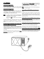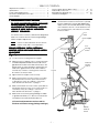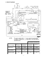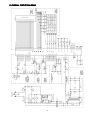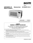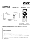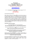
1
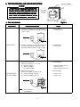
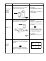
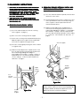
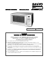
File No :
SER
VICE MANUAL
SERVICE
Micr
owave Oven
Microwave
EM-F3400SW
Pr
oduct Code No.
Product
(U.S.A.)
437 450 57
CAUTION
WARNING TO SER
VICE TECHNICIANS
SERVICE
PRECAUTIONS TO BE OBSERVED BEFORE AND DURING
SERVICING TO AVOID POSSIBLE EXPOSURE TO
EXCESSIVE MICROWAVE ENERGY
(a)
Do not operate or allow the oven to be operated with the door open.
(b) Make the following safety checks on all ovens to be serviced before activating the magnetron or other
microwave source, and make repairs as necessary :
(1) Interlock operation, (2) proper door closing, (3) seal and sealing surfaces (arcing, wear, and other damage),
(4) damage to or loosening of hinges and latches, (5) evidence of dropping or abuse.
(c)
Before turning on microwave power for any service test or inspection within the microwave generating
compartments, check the magnetron, wave guide or transmission line, and cavity for proper alignment, integrity,
and connections.
(d) Any defective or misadjusted components in the interlock, monitor, door seal, and microwave generation and
transmission systems shall be repaired, replaced, or adjusted by procedures described in this manual before
the oven is released to the owner.
(e)
A microwave leakage check to verify compliance with the Federal performance standard should be performed
on each oven prior to release to the owner.
REFERENCE NO. SM-860304
In the area emitting the highest reading, switch the meter
to SLOW RESPONSE, and take a reading for minimum of
three (3) seconds. We recommended the pattern outline
shown below when the door surface is surveyed.
CAUTION
For micr
owave ener
gy emission
microwave
energy
On every service calls, check for microwave energy
emission, must be made according to the following manner.
gy emission
Measur
ement of ener
Measurement
energy
Measurement must be made with the microwave oven
operating at its maximum output and containing a load of
275±15 milliliters of tap water initially at 20o±5o celsius (68
±9oF) placed within the cavity at the center.
NOTE : The water container must be a 600 milliliter beaker
and made of an electrically none conductive
material such as glass or plastic.
The cook tray must be in place when measuring
emission.
A properly operating door and seal assembly will normally
register emission on greater than 4mW/cm2 to allow for
measurement uncertainty with the cooking shelf or tray in
place.
NOTE : Periodically check to be sure that the probe tip is
not worn or dirty.
The following U.S. standard applies to microwave ovens :
21 CFR 1030.10, Performance Standard for Microwave
Ovens.
It requires that the power density of the microwave
radiation emitted by a microwave oven shall not exceed
five (5) milliwatts per square centimeter at any point 5
centimeter (about 2 inches) or more from the external
surface of the oven.
All microwave ovens exceeding the emission level of
4mW/cm 2 must be reported to Dept. of Service for
microwave ovens and the manufacturer immediately and
the owner should be told not to use the microwave oven
until it has been repaired completely.
If a microwave oven is found to operate with the door open,
report to Dept. of Service, the manufacturer and CDRH*
All repairs must be performed in such a manner that
immediately. Also tell the owner not to use the oven.
owave ener
gy emission ar
e minimal.
micr
are
microwave
energy
*CDRH : Center for Device and Radiological Health.
Follow the instructions supplied with a detector being used
and performed an R.F. emission test around the door front
and edges and all edges and vent of the outer case. The
cabinet (wrapper) must be in place and the oven fully
assembled.
When performing emission survey, with the meter on FAST
RESPONSE the movement of a detector probe shall not
exceed one (1) inch per second.
-i-
The interlock monitor switch acts as the final safety switch
protecting the customer from microwave radiation. If the
interlock monitor switch operates to blow the fuse with
interlocks failed, you must replace all interlock switches
primary and secondary interlock switches and the monitor
switch with new ones because the contacts of those
interlock switches may be melted and welded together.
- TABLE OF CONTENTS Adjustment Procedures ...................................................
Specifications ..................................................................
Power Output Measurement ...........................................
Precautions and Repair Service Tips ..............................
Circuit Diagram ...............................................................
1
2
2
2
3
1 . ADJUSTMENT PROCEDURES
TO A
VOID POSSIBLE EXPOSURE TO MICROW
AVE
AVOID
MICROWA
ENERGY LEAKAGE, THE FOLLOWING
ADJUSTMENT OF THE INTERLOCK SWITCHES
SHOULD BE MADE ONL
Y BY AUTHORIZED
ONLY
SER
VICE PERSONNEL.
SERVICE
The SANYO service center should have the designated
detector to measure the microwave energy leakage
after the repair or adjustment.
Test Procedures and Troubleshooting ....................
Disassembly Instructions .......................................
Exploded View and Parts List ................................
Overall Circuit Diagram ..........................................
4 ~ 10
11 ~ 14
15 ~ 20
21
NOTE : If the interlock monitor circuit operates and at the
same time the fuse blows with the door opened,
be sure to replace the control circuit board because
relay 2 on the control circuit board, the door sensing
switch and the electric circuit related on the
door sensing switch, which act as Secondary
Interlock Switch.
Door
Latch
Lever Stopper
NOTE : Detector to be used at the service center is
NARDA 8100, 8200 or the equivalent.
Door
Sensing
Switch
PRIMAR
Y INTERLOCK SWITCH, INTERLOCK
PRIMARY
MONITOR SWITCH AND DOOR SENSING SWITCH
ADJUSTMENT
(Figure 1)
(1) Loosen 2 screws securing the lever stopper.
(2) Adjust the lever stopper position so that it is pushed
forward and pull backward until there is about zero
gap between the latch lever and switch body on the
primary interlock switch and at the same time there
is about zero gap between the door latch and the
switch body on the door sensing switch when the
door latch is securely locked.
Interlock
Monitor
Switch
Screws
(3) Tighten the lever stopper screws securely.
(4) Make sure the interlock monitor switch closes after
the primary interlock switch opens when the door
is opened very slowly, according to “CHECKOUT
PROCEDURE FOR SWITCHES” on page 6.
(5) Make sure the interlock monitor switch opens before
the primary interlock switch closes when the door is
closed very slowly, according to “CHECKOUT
PROCEDURE FOR SWITCHES” on page 6.
(6) Make sure the microwave energy leakage should be
no greater than 4mW/cm2 to allow for measurement
uncertainty when measured with a detector.
(All service adjustments must be made for
minimum microwave energy leakage readings.)
Figure 1
-1-
Latch
Lever
Primary
Interlock
Switch
4 . PRECAUTIONS AND REP
AIR SER
VICE TIPS
REPAIR
SERVICE
2 . SPECIFICA
TIONS
SPECIFICATIONS
Rated Power Consumption .. 1480W.
Microwave Output ................ 1050W.
Frequency ............................. 2,450MHz±50MHz.
Power Supply ........................ 120V±12V, 60Hz.
Rated Current ....................... 12.9 Amp.
Safety Devices ..................... Thermal Fuse open at
332°F (167°C) for Cavity.
Thermal Protector open at
252°F (122°C) for Magnetron.
Fuse (Cartridge Type 20A)
Primary Interlock Switch,
Door Sensing Switch and
Relay 2.
Interlock Monitor Switch.
Timer ..................................... Electronic Digital, up to
99 min. 99 sec.
Overall Dimensions ................ 205/8”(W) x 161/2”(D) x 113/8”(H)
Oven Cavity Size .................. 133/4”(W) x 145/8”(D) x 81/2”(H)
Turn Table Diameter .............. 10 7/8”
Effective Capacity of
Oven Cavity .......................... 1.1 Cubic Feet.
Net Weight ........................... Approx. 34.5 Lbs.
PRELIMINAR
Y
PRELIMINARY
A. SINCE NEARL
Y 2,000 VOL
TS EXISTS IN SOME CIRNEARLY
VOLTS
CUITS OF THIS MICROW
AVE OVEN, REP
AIRS SHOULD
MICROWA
REPAIRS
BE CARRIED OUT WITH GREA
GREATT CARE.
B. TO A
VOID POSSIBLE EXPOSURE TO MICROW
AVE
AVOID
MICROWA
ENERGY LEAKAGE, THE FOLLOWING PRECAUTIONS
VICING.
MUST BE TTAKEN
AKEN BEFORE SER
SERVICING.
(1) Before the power is applied :
(a) Open and close door several times to make sure the
primary interlock switch, the interlock monitor switch
and the door sensing switch operate properly.
(Listen for the clicking sound from the switches).
Make sure the interlock monitor switch closes after
the primary interlock switch is opens when the door
is opened. (See pages 1 and 6).
(b) Make sure the perforated screen and the choke dielectric of the door are correctly mounted.
(2) After the power is applied :
(a) Open and close the door to see if the interlock mechanism operates properly.
(b) Check microwave energy leakage with a leakage
detector and confirm the energy leakage should be
no greater than 4mW/cm2 to allow for measurement
uncertainty.
3 . POWER OUTPUT MEASUREMENT
NOTE
The power output specification, 1050W. on this model is
measured with IEC measurement. The power output is
measured with two (2) liters water is equivalent to 1050W.
in measurement with IEC, when measured with the following
power output.
(3) Do not operate the unit until it is completely repaired,
if any of the following conditions exists :
(a)
(b)
(c)
(d)
Door does not close firmly against the cavity front.
The hinge is broken.
The choke dielectric or the door seal is damaged.
The door is bent or warped, or there is any other
visible damage to the oven that may cause microwave
energy leakage.
NOTE : Always keep the seal clean.
(1) Fill two beakers (glass or plastic) with each one liter of
tap water (about 20°C) and measure the water temperature.
(Use a thermometer with a 1/10 degree gauge).
(e) Make sure that there are no defective parts in the
interlock mechanism.
(2) Place the beakers side by side in the center of the glass tray.
(3) Close the door, set the “TIME” for two minutes. (“200” in
the display window). Touch the “START” key and heat
the water exactly for two minutes.
(4) Take the beakers out, immediately stir the water and
measure the water temperature respectively.
(f) Make sure there are no defective parts in the
microwave generating and transmission assembly.
(especially waveguide).
(4) The following items should be checked after the unit
is repaired :
(5) Calculate the temperature rise of water in each beaker.
Then calculate the average value of two temperature rises.
Output power can be calculated by the equation :
Power Output (W) = 70 x ∆t
Where ∆t is an average temperature rise in degrees
Centigrade.
(6) Power Output shall be in the following range :
Minimum
Maximum
Average Temperature Rise
19.6°F (10.9°C)
20.0°F (14.0°C)
(a) The interlock monitor switch is connected correctly
and firmly.
(b) The magnetron gasket on the magnetron is properly
positioned.
(c) Waveguide and oven cavity are intact (no leakage of
microwave energy).
(d) The door can be properly closed and the safety
switches work properly.
Power Output
763W
980W
(e) The oven must be stopped when the door is opened
or the time is up.
(7) Power Output is affected by the line voltage under load.
For correct Power Output measurement, the line voltage
under load must be 120±1 volts.
The oven must not be operated with any of the above
components rremoved
emoved or bypassed.
-2-
5. CIRCUIT DIAGRAM
Figure 2
S E C OND A RY INTE RL OC K
S W ITC H M A D E
C OND ITION
•
P RIM A RY
INTE RL OC K
S W ITC H
INTE RL OC K
M ONITOR
S W ITC H
D OOR
S E NS ING
S W ITC H
R E L AY 2
C OM
C OM
C OM
C OM
NO
NC
NO
NO
•
•
•
D OOR OP E N
D OOR C L OS E
•
-3-
Filament Windings
6. TEST PROCEDURES AND TROUBLESHOOTING
CAUTION
- DISCONNECT THE POWER SUPPL
Y CORD FROM
SUPPLY
THE W
ALL OUTLET WHENEVER REMOVING THE
WALL
CABINET FROM THE UNIT
UNIT,, PROCEED WITH THE
TESTS ONL
Y AFTER DISCHARGING THE HIGH
ONLY
VOL
ACITOR AND REMOVING THE LEAD
VOLTTAGE CAP
CAPACITOR
WIRES FROM THE PRIMAR
Y WINDING OF THE
PRIMARY
HIGH VOL
VOLTTAGE TRANSFORMER. (SEE FIGURE 3)
Secondary
Windings
Primary
Windings
Figure 3
A. TEST PROCEDURES
COMPONENT
CHECKOUT PROCEDURE
RESUL
RESULTT
1) Check for resistance : Across the filament
terminals of the Magnetron with an Ohm-Meter
on R x 1 scale.
Normal reading :
Less than 1 Ohm.
Ohm-Meter
Figure 4
MAGNETRON
2) Check for resistance : Between each filament
terminal of the Magnetron and the chassis
ground with an Ohm-Meter on highest scale.
Normal reading :
Infinite Ohms.
Ohm-Meter
Figure 5
HIGH-VOLTAGE
TRANSFORMER
1) Measure the resistance :
With an Ohm-Meter on R x 1 scale.
a. Primary winding :
b. Filament winding :
c. Secondary winding :
Normal readings :
2) Measure the resistance :
With an Ohm-Meter on highest scale.
a. Primary winding to ground.
b Filament winding to ground.
Normal readings :
Approximately 0.38 Ohms.
Less than 1 Ohm.
Approximately 82.0 Ohms.
Ohm-Meter
Figure 6
Note : Remove varnish of
measured point.
-4-
Infinite Ohms.
Infinite Ohms.
COMPONENT
HIGH-VOLTAGE
CAPACITOR
including
BLEEDER
RESISTOR
CHECKOUT PROCEDURE
RESUL
RESULTT
Measure the resistance : Across two terminals
with an Ohm-Meter on highest scale.
Normal reading :
Momentarily indicates several Ohms,
and gradually returns to 10 Meg-Ohms.
Abnormal reading :
Indicates continuity or 10 Meg-Ohms
from the beginning.
Ohm-Meter
Figure 7
Measure the resistance : Across two terminals
with an Ohm-Meter on R x 10,000 scale.
Ohm-Meter
Normal reading :
Indicates about the middle position in
one direction (forward direction) and
infinite ohms in the reverse direction,
using meter which is provided with a
9 volt battery.
NOTE
HIGH-VOLTAGE
DIODE
- Some digital meter may show over
even in a forward direction because
low measuring voltage of meter does
not allow the meter current to pass
through the High Voltage Diode.
Abnormal reading :
Indicates continuity or infinite Ohms
in both directions.
Figure 8
Measure the voltage : Between test point TP-1,
TP-2 and Ground. (See Control Circuit Board on
page 19).
CONTROL
CIRCUIT
BOARD
NOTE
- Proceed with the check of the Step-Down
Transformer, to see if any one of the measured
values is different from the specified values.
-5-
Test
Point
TP-1
TP-2
Voltage
-5V
DC
-15V
DC
COMPONENT
CHECKOUT PROCEDURE
RESUL
RESULTT
Measure the resistance between terminals of
FPC connector after removing it from S101.
(Figure 9).
TOUCH KEY
BOARD
NOTE
- When reconnecting the FPC connector, make
sure the holes on the connector are properly
inserted in hooks of the plastic fastener in S101.
5
POWER
LEVEL
TOTAL
QUICK
ON
6
1
7
2
8
3
9
PIZZA
SLICE
S TAR T
4
STOP /
CLEAR
VEGETABLE
FRESH
CLOCK
DEFROST
QUICK
DEFROST
SOUP /
BEVERAGE
When
touched
When not
touched
Less than
1K Ohms
More than
1 MEG Ohms
When checking “START” key, connect
Ohm-Meter as illustration below.
Ohm-Meter
MA
TRIX CIRCUIT FOR
MATRIX
TOUCH KEY BOARD
FPC CONNECTOR
0
Resistance
value
MORE +
LESS -
POTATO
FROZEN
KITCHEN
ENTREE
TIMER
FROZEN
ADD
30 SEC
VEGETABLE
CUSTOM
POPCORN PROGRAMS
TERMINALS OF FPC CONNECTOR
Figure 9
CHECKOUT PROCEDURE FOR SWITCHES
Disconnect the lead wires from the switches and check for the continuity of the switches, connecting an Ohm-Meter
to its terminals.
SWITCHES
(See Figure 1 on page 1)
CHECKOUT PROCEDURES
DOOR OPEN
DOOR CLOSED
Primary Interlock
Terminals “COM” and “NO”
Door Sensing
Interlock Monitor
CAUTION
:
Terminals “COM” and “NC”
After checking the switches, make sure that the interlock monitor switch is properly connected according
to the CIRCUIT DIAGRAM on page 3.
-6-
-7-
b
Check power supply
voltage on Control Circuit
Board. (See page 5)
Control Circuit
Board.
Check 120VAC power supply
of connector S1 between Pin
1 and Pin 3 after removing
connector S1 from Control
Circuit Board.
a
(1) PROBLEM
No display or mis-display in
the display window by
touching the keys.
STEP
B. TROUBLESHOOTING
Voltage
incorrect.
Each voltage
OK.
120 volts.
0 volt.
Check resistance of
Touch Key Board.
(See page 6)
Touch Key Board.
Resistance
incorrect
(ON or OFF).
Each resistance
OK.
Check continuity of Fuse,
Thermal Protector for
Magnetron, Thermal Protector
for Cavity and AC Power Cord.
If the Fuse is blown, see “E,
REMOVING FUSE” on page 13.
SEQUENCE
Normal Touch
Key Board.
Normal Control
Circuit Board.
Replace Control
Circuit Board.
Normal Control
Circuit Board.
Replace Touch
Key Board.
Correct seating of
connector S101 or
replace Control
Circuit Board.
Replace it
if necessary.
Runs
Runs
Runs
PROBLEM
1-b
Runs
R E S U LLTT
-8-
Door Sensing Switch.
Touch “START” key and
measure voltage between
white wire lead and black wire
lead for primary winding of
H.V. transformer after removing
the wire leads from terminals of
H.V. Transformer.
a
(3) PROBLEM
Oven does not heat up.
Continuity
OK.
0 Volts.
AC 120 Volts.
No
continuity.
Check contact
of Connector
S102.
CHECK : 1 . Power Supply to Oven.
2 . Primary Interlock Switch.
3 . Thermal Protector for Magnetron and
Thermal Protector for Cavity.
Check continuity of connector
S102 between Pins (O and BL)
with the door closed after
removing connector S102 from
Control Circuit Board.
a
(2) PROBLEM
Cooking operation will not
start.
STEP
Poor
contact.
Contact
OK.
SEQUENCE
Correct
seating.
Replace Control
Circuit Board.
Adjust or replace
Door Sensing Switch.
(See page 1)
Normal
contact.
Normal Control
Circuit Board.
Normal Door
Sensing Switch.
Runs
PROBLEM
3-b
Runs
Runs
PROBLEM
3-a
R E S U LLTT
-9-
Check resistance of each
winding after removing
lead wires. (See page 4)
H.V. Transformer.
a
Check operation of Blower
Motor when “START” key
is touched.
(4) PROBLEM
Low microwave power
output.
b
STEP
Normal
operation.
Replace H.V.
Transformer.
Check H.V. Capacitor or H.V.
Diode with an Ohm-Meter after
removing lead wires.
(See page 5)
Normal
resistance
Normal H.V.
Capacitor or
H.V. Diode.
Normal
Magnetron.
Normal Blower
Motor.
Replace Control Normal Control
Circuit Board.
Circuit Board.
Replace
Blower
Motor.
Normal thermal protector for
Magnetron or Thermal
Protector for Cavity.
Replace H.V.
Capacitor or
H.V. Diode.
Replace
Magnetron.
Resistance
incorrect.
Replace Thermal Protector
for Magnetron or Thermal
Protector for Cavity.
Normal H.V.
Transformer.
Defective
H.V. Capacitor
or H.V. Diode.
Normal H.V.
Capacitor or
H.V. Diode.
No
Temporarily short
operation. across terminals of
Thermal Protector for
Magnetron or Thermal
No
Protector for Cavity
Measure resistance
operation.
by using jumper lead.
of Blower Motor
Approx. 63 ohms.
Normal
operation.
Resistance
incorrect.
Resistance
OK.
SEQUENCE
Runs
Runs
Runs
PROBLEM
3-b
Runs
Runs
Runs
R E S U LLTT
- 10 -
Set power level
at “50”.
a
H.V. Transformer.
Touch “START” key and
measure voltage between
white wire lead and black wire
lead for primary winding of
H.V. Transformer after
removing the wire leads from
terminals of H.V. Transformer.
Check normal operation
of Control Circuit Board.
(6) PROBLEM
No buzzing by touching keys
and at the end of cooking.
a
(5) PROBLEM
The Magnetron operates on
high level when a lower
cook power is selected.
STEP
120V
Voltage cycles
on and off.
SEQUENCE
Replace Control
Circuit Board
Replace Control
Circuit Board
Normal Control
Circuit Board
Normal Control
Circuit Board
Runs
Runs
No problem.
Measure water
temperature
rise exactly.
R E S U LLTT
7 . DISASSEMBL
Y INSTRUCTIONS
DISASSEMBLY
• OVEN MUST BE DISCONNECTED FROM ELECTRICAL
OUTLET WHEN MAKING REPLACEMENTS, REP
AIRS,
REPAIRS,
ADJUSTMENTS AND CONTINUITY CHECKS BEFORE
PROCEEDING WITH ANY REP
AIR WORK. AFTER
REPAIR
AIT A
DISCONNECTING, W
ATT LEAST 1 MINUTE, UNTIL
WAIT
THE CAP
ACITOR IN THE HIGH-VOL
CAPACITOR
HIGH-VOLTTAGE AREA
HAS FULL
Y DISCHARGED.
FULLY
• WHEN REPLACING ANY DOOR MICROSWITCH,
REPLACE WITH THE SAME TYPE SWITCH SPECIFIED
ON THE P
AR
TS LIST
PAR
ARTS
LIST..
A. REMOVING DOOR SENSING SWITCH
(Figures 1 on page 1, 10-a)
(1) Disconnect all wire leads from the door sensing
switch. (Figure 1 on page 1)
(2) Remove 2 screws securing the lever stopper.
B. REMOVING PRIMAR
Y INTERLOCK SWITCH AND
PRIMARY
INTERLOCK MONITOR SWITCH
(Figure 10-b)
(1) Disconnect all wire leads from primary interlock and
Interlock monitor switch.
(2) Pull the primary interlock switch or Interlock monitor
switch upward at the same time while pushing the
switch stoppers to allow a space between the
switch body and catches.
(3) Make necessary adjustments or replacement of
switch by the reversing step (2) and check microwave energy leakage according to “1. ADJUSTMENT
PROCEDURES” on page 1, after it is replaced with
new one, and check proper operation of it according
to “CHECKOUT PROCEDURE FOR SWITCHES” on
page 6.
(3) Push the door sensing switch upward while pressing
adjacent upper switch stopper of lever stopper and
lower switch stopper down (Figure 10-a).
Switch Stoppers
(4) Then remove it by lightly pressing the switch toward
you (Figure 10-a).
(5) Make necessary adjustments or replacements of the
door sensing switch by reversing step (3) and check
microwave energy leakage according to “1.
ADJUSTMENT PROCEDURES” on page 1, after it is
replaced with new one, and check proper operation
of it according to “CHECKOUT PROCEDURE FOR
SWITCHES” on page 6.
Interlock
Monitor
Switch
Primary
Interlock
Switch
Upper
Switch
Stopper
Door
Sensing
Switch
Switch Stoppers
Figure 10-b
Lower
Switch
Stopper
Figure 10-a
Interlock Switch Replacement - when replacing
faulty switches, be sure switch mounting tabs are
not bent, broken or otherwise deficient in their
ability to secure the switches in place.
- 11 -
C. REMOVING BLOWER MOTOR
(Figures 11 (Top View) and 12).
Duct (mag. exhaust)
(1) Remove screw securing the stay.
(2) Disconnect all lead wires from the blower motor
and H.V. capacitor.
Blower Base
Thermal Protector
Screw
(3) Remove 3 screws securing the blower base and
disengage 3 hooks from the rear plate of cavity
(Figure 12).
(4) Remove 1 screw securing the blower motor with
the blower base.
D. REMOVING MAGNETRON
(Figure 11 (Top View))
Stay
Duct (mag. intake)
After removing the blower motor :
Figur
e 11 (T
op V
iew)
Figure
(Top
View)
(1) Remove duct (mag. exhaust). Remove the screw
securing the stay.
(2) Remove 1 screw securing the thermal protector.
(3) Disconnect 2 lead wires from the magnetron.
(4) Remove 4 screws securing the magnetron to the
waveguide.
(5) Take out Magnetron VERY CAREFULLY.
Screw
NOTE
1.
When removing the magnetron from the cavity or
wave guide, use a proper care so that the dome of
the magnetron does not hit any adjacent parts of
microwave oven.
2.
Make sure that the contact face of the magnetron
gasket is free from any damage or deformation.
3.
Adjust the position of the magnetron properly, so
that it correctly sits in place and the magnetron
gasket is in contact with the mounting rim evenly.
4.
While holding the magnetron under this condition,
tighten mounting screws or nuts with your fingers
temporarily.
5.
Further tighten the screws or nuts with a box
wrench, giving one or two turns to each of the
screws (or nuts) alternatively so that the
magnetron is mounted on to the bracket uniformly.
6.
After replacing the magnetron, be sure to check the
microwave energy leakage with a leakage detector
and confirm the leakage is below 4mW/cm2.
- 12 -
Hook
Blower Motor
Figure 12
E. REMOVING FUSE
Remove the 20A fuse with a screwdriver.
--
F.
NOTE
When replacing the 20A fuse, be sure to use an exact
repair part.
--
If the 20A fuse blows immediately, check the primary
interlock switch, the relay 2 (on the control circuit board)
and the interlock monitor switch according to,
“CHECKOUT PROCEDURE FOR SWITCHES” on page 6.
And make sure to check the microwave energy leakage
according to, “1. ADJUSTMENT PROCEDURES” on page
1, when the primary interlock switch, the relay 2 or the
interlock monitor switch is adjusted or replaced.
--
If the primary interlock switch, the relay 2 and the interlock
monitor switch operate properly, determine which of the
following is defective : control circuit board, blower motor,
high voltage transformer, high voltage capacitor, high voltage
diode or magnetron.
Control Base
REMOVING CONTROL CIRCUIT BOARD
(See exploded view on page 18 and Figure 13)
(1) Remove the connector S1, S102 and the connector for
the relay 2 from the control circuit board.
(2) Remove 1 screw securing the control panel complete to
the oven cavity.
(3) Remove the FPC connector from the connector S101
while grasping up both lever ends of the plastic fastener.
Control Frame
Figure 13
Control Sheet
Control Frame
(4) Remove 2 screws securing the control circuit board to
the control base.
(5) Lift up the control circuit board from its lower side and
take it out from the control base.
Touch Key
Board
G. REMOVING TOUCH KEY BOARD
(Figure 14)
After removing the control circuit board :
(1) Remove control base while lifting it up at the right side
and take it out from the control frame.
(2) Remove control sheet which is glued to touch key board.
(3) Remove the touch key board which is held on the control
base bracket with the adhesive tape.
Figure 14
- 13 -
H. REMOVING DOOR
J. REMOVING CA
VITY COVER
CAVITY
(Figure 16)
(1) Remove 2 hex nuts securing the upper hinge.
(1) Remove a screw from the cavity compartment.
(2) Tilt the top of the door toward you.
(3) Lift up the door to remove it.
NOTE
- After replacing the door, be sure to check that the
primary interlock switch, the door sensing switch
and the interlock monitor switch operate normally.
(See page 1).
Cavity Cover
- After replacing the door, check for microwave energy
leakage with a leakage detector. Microwave energy
leakage must be below the limit of 4mW/cm2 to
allow for measurement uncertainty.
Screw
I. DISASSEMBLING DOOR
(Figure 15)
Figure 16
(1) Insert a thin flat-blade screwdriver between the
choke dielectric and the door main frame and lift
up the choke dielectric to release hooks one by
one. (Figure 15).
K. REMOVING TURNT
ABLE MOTOR COVER
TURNTABLE
(2) Remove the choke dielectric.
(Figure 17)
(3) To detach the door cover, insert a thin flat-blade
screwdriver between door cover and door panel
and release the projections inside door cover.
(1) Turn over the oven on its back.
(4) To detach the door panel, insert a thin flat-blade
screwdriver between the door cover and door
main frame.
Hooks
(2) Cut the 6-joints of the bottom plate using diagonal
pliers (nipper).
(3) Separate the motor cover from bottom plate.
(4) Remove 2 screws securing turntable motor to the
cavity and take it out.
Note : Bent the cut joints inside slightly for safety
and be careful of sharp edge.
Hooks
Hooks
6 Joints
Motor Cover
Bottom Plate
Door
Main
Frame
Choke
Dielectric
Hooks
Figure 15
NOTE
- The choke dielectric may be damaged when
it is removed. When reinstalling it replace it
with new ones if it is damaged.
- After installing the door in place, check for
microwave energy leakage with a detector.
Microwave energy leakage must be below the
limit of 4mW/cm2 to allow for measurement
uncertainty.
Figure 17
- 14 -
8 . EXPLODED VIEW AND P
AR
TS LIST
PAR
ARTS
CAVITY PARTS
***
Key
No.
1
2
3
4
5
6
7
8
9
10
11
12
13
ALL SERVICE ON MICROWAVE OVENS SHOULD BE PERFORMED BY A QUALIFIED TECHNICIAN USING
APPROVED TESTING EQUIPMENT. CUSTOMERS SHOULD NOT ATTEMPT TO REPLACE PARTS IDENTIFIED
BY A TRIPLE ASTERISK (***).
Part No.
617
411
411
617
411
617
617
411
617
617
411
617
411
228
082
160
171
160
228
221
010
138
221
011
180
089
Description
8321
5201
6007
6863
6106
8345
3590
5808
5601
6089
0802
6137
2500
Cabinet
SCR TPG TRS 4 x 10 Z1
SCR TPG TRS + SRT 4 x 10 Z1
Power Cord
SCR S-T TRS + SRT 4 x 10 Z1
Oven Cavity*** (Not Service Part)
Gear Motor
SCR EVR PAN 4 x 10 Z1
Bottom Plate*** (Not Service Part)
Plastic Foot with Canoe Clip
Bolt Hex + SW + W5 x 14 Z1***
Hinge, Lower***
Washer F 5 x 10 x 0.8
Q’ty
Key
No.
1
8
2
1
1
1
1
2
1
4
2
1
1
14
15
16
17
18
19
20
21
22
23
24
25
26
- 15 -
Part No.
617
617
617
617
617
617
411
411
617
617
120
220
204
073
204
162
069
006
200
080
Description
8481
9401
9489
5889
9403
1938
1707
6604
0381
5315
617 229 9013
Q’ty
Insulation Sheet
Turn Table Shaft
Roller Base Assy
Rotating Tray
Antenna Complete
Cavity Cover
SCR TPG TRS 4 x 6 DA
SCR TPG PAN 3 x 6 Z1
Thermal Fuse 167oC
Special Washer
1
1
1
1
1
1
1
1
1
1
Special Screw
2
SWITCHES AND MICROWAVE PARTS
***
Key
No.
ALL SERVICE ON MICROWAVE OVENS SHOULD BE PERFORMED BY A QUALIFIED TECHNICIAN USING
APPROVED TESTING EQUIPMENT. CUSTOMERS SHOULD NOT ATTEMPT TO REPLACE PARTS IDENTIFIED
BY A TRIPLE ASTERISK (***).
Part No.
Description
1
2
3
4
5
6
7
8
9
10
11
411
617
617
411
617
415
423
617
617
617
617
082
229
199
006
129
002
020
233
221
162
197
5201
9020
8283
6604
1001
9508
3408
0006
3606
1990
6670
12
13
14
15
16
617
411
617
617
617
182
011
229
005
230
2373
5609
7903
5147
2713
SCR TPG TRS 4 x 10 Z1
H.V Transformer,*** N6T-P410
Stay, Cavity & Magnetron
SCR TPG PAN 3 x 6 Z1
Thermostat, Magnetron 135oC
Magnetron, 2M253H(M)N***
Fuse, 125V 20A
Fuse Holder
Lead Wire Ass’y (including Diode)
Blower Base
H.V Capacitor including Resistor,
0.97uf 2.2KV
Capacitor Band
Bolt Hex 4 x 10 Z1
Duct, Mag. Exhaust
Lamp, 120V 20W
Lamp Socket
Q’ty
9
1
1
1
1
1
1
1
1
1
1
1
4
1
1
1
Key
No.
Part No.
17
18
19
20
21
617
411
617
617
617
22
617 221 4061
23
617 221 4078
24
25
26
27
28
29
617
411
411
617
617
- 16 -
197
082
196
245
221
Description
245
102
129
117
124
7417
5201
8507
6256
4078
6096
5907
5805
3505
3796
Q’ty
Blower Motor
SCR TPG TRS 4 x 10 Z1
Blower Fan
Latch Lever***
Micro Switch,*** Primary Interlock
AM51630C53F2
Micro Switch,*** Interlock Monitor
AM50620C53
Micro Switch,*** Door Sensing
AM51630C53F2
1
2
1
1
1
Lever Stopper***
SCR ETG TRS 4 x 10 N2
SCR TPG BIN 3 x 10 Z1
Harness, Door Sensing
Lead Wire Ass’y
1
2
1
1
1
1
1
DOOR PARTS
***
Key
No.
ALL SERVICE ON MICROWAVE OVENS SHOULD BE PERFORMED BY A QUALIFIED TECHNICIAN USING
APPROVED TESTING EQUIPMENT. CUSTOMERS SHOULD NOT ATTEMPT TO REPLACE PARTS IDENTIFIED
BY A TRIPLE ASTERISK (***).
Part No.
Description
1
2
3
617 229 2403
617 181 4170
617 229 2007
4
617 124 0948
Door Cover***
Door Panel***
Door Main Frame*** (Also
order Door Sheet when replacing
Door Main Frame)
Choke Dielectric***
Q’ty
Key
No.
1
1
1
5
6
7
8
9
10
1
- 17 -
Description
Part No.
617
411
617
411
617
617
222
054
180
011
101
179
0123
1903
6151
0802
1494
2478
Door Sheet
Nut Hex + Flg W / SRT 5***
Hinge, Upper***
Bolt Hex + SW + W 5 x 14***
Spring***
Door Latch***
Q’ty
1
2
1
2
1
1
CONTROL PANEL PARTS
***
Key
No.
ALL SERVICE ON MICROWAVE OVENS SHOULD BE PERFORMED BY A QUALIFIED TECHNICIAN USING
APPROVED TESTING EQUIPMENT. CUSTOMERS SHOULD NOT ATTEMPT TO REPLACE PARTS IDENTIFIED
BY A TRIPLE ASTERISK (***).
Part No.
Description
1
617 230 7787
2
617 233 5872
3
617 229 3646
Control Sheet*** (Also order
Touch Key Board when replacing
Control Sheet)
Touch Key Board*** (Also order
Control Sheet when replacing
Touch Key Board)
Control Frame***
Q’ty
1
1
1
PRINTED MATTER (Items Not Illustrated)
Key
No.
Part No.
Description
617 232 7594
Operating Instructions
(English / Spanish)
Carton Box Complete
Name Plate
617 230 9095
617 230 7664
Q’ty
1
1
1
- 18 -
Key
No.
4
5
6
7
8
9
Part No.
617
411
617
411
617
617
151
160
230
129
080
229
Description
4377
6205
2324
5805
9559
3691
Control Base***
SCR TPG TRS+SRT 4 x 10 Z1
Power & Control Circuit Board***
SCR TPG BIN 3 x 10 Z1
Spring, Door Release Lever***
Door Release Lever***
Q’ty
1
1
1
1
1
1
CONTROL CIRCUIT BOARD
(Part No. 617 230 2324
2324)
40800
- 19 -
CONTROL CIRCUIT BOARD
(Part No. 617 230 2324
2324)
Key No.
Order Part No.
Description
Q’ty
409 468 0209
Order Part No.
Description
Q’ty
R901,906,
909
R903
401 037 5608
MT-Glaze, 10K ohms
+-1%, 10W.
MT-Glaze, 3.3K ohms
+-1%, 10W.
3
R902,905,
907, 908
R904
401 038 6406
MT-Glaze, 4.7K ohms
+-1%, 10W.
MT-Glaze, 820 ohms
+-1%, 10W.
4
R106
401 012 4404
1
R101,112
401 012 5609
Carbon, 100 ohms
+-5%, 1/4W.
Carbon, 1K ohms
+-5%, 1/4W.
R11 ~ 14
401 013 4106
4
R58
401 013 6308
Carbon, 120 ohms
+-5%, 1/4W.
Carbon, 12K ohms
+-5%, 1/4W.
R105
401 016 4707
1
R107,108
401 016 9603
Carbon, 22K ohms
+-5%, 1/4W.
Carbon, 27 ohms
+-5%, 1/4W.
R109
401 018 2701
1
R103,104,
51 ~ 53
401 020 2805
Carbon, 330 ohms
+-5%, 1/4W.
Carbon, 47K ohms
+-5%, 1/4W.
RESISTORS.
INTEGRATED CIRCUIT
IC11
Key No.
IC LM8847B-1A43.
1
TRANSISTORS
Q901
Q103
405 138 8506
405 035 4809
TR FMA9A.
2SC1685-Q-TP.
1
1
Q101,102
405 082 4609
DTA123YS-TP.
2
DIODES
D11
D101~106
108
407 012 0200
407 012 4406
1N4002-TP.
1SS133-T77.
1
7
ZD101
ZD11
407 132 2306
407 056 8507
HZS3.9ENB2.
RD5.1ESB2.
1
1
401 038 3603
401 039 0304
1
1
2
1
2
5
RESISTOR BLOCK
CAPACITORS
C104, 105,
108
403 069 1207
C103, 106,
107
C101
403 142 5306
C12
403 105 3806
C11
403 152 7208
403 049 2606
Ceramic, 1000PK,
+-5%, 50V.
3
RB101
617 010 3558
Resistor Network
1
Ceramic, 0.01mfd,
+-5%, 50V.
Electrolytic, 1mfd,
+-20%, 50V.
3
RB902
RB901
402 080 7700
401 083 2108
MT-Glaze, 10K x 4
MT-Glaze, 4.7K x 7
1
1
1
MISCELLANEOUS
Electrolytic, 47mfd,
+-20%, 10V.
Electrolytic, 1000mfd,
+-20%, 25V.
1
1
BZ1
420 000 6800
Buzzer, PKM22EPT.
1
VST1
LCD1
407 118 5505
617 209 2218
Varistor ENC 471D-10A.
Display Tube.
1
1
RL1
RL2
617 201 3978
617 141 0549
Relay, G5N-1A-DC12.
Relay, DU12D1-1PR.
1
1
RS1
S1
617 128 3372
617 169 4109
Ceramic Oscillator.
Connector.
1
1
S101
S102
617 126 8959
617 111 1392
Connector.
Connector.
1
1
PT1
617 230 4984
1
2
617 178 4268
Step-Down Transformer.
P6K-P410
Part Base.
JB1, 2
J9 ~ 13
16, 17
617 132 5744
617 079 4299
Noise Filter.
Jumper.
2
7
J101~ 103
617 079 4237
Jumper.
3
- 20 -
1
9 . OVERALL CIRCUIT DIAGRAM
- 21 -