1
US008303297B2
(12) Ulllted States Patent
(10) Patent N0.:
Tompkins et al.
(54)
(45) Date of Patent:
5,122,053 A *
CONTROLLING COMBUSTION IN A
5,158,446
BURNER
5,472,050 A * 12/1995 Rhoten et 211.
*
6/1997
Tillander
Inventors:
Gene Tompkins,Arkansas City, KS
6,035,810 A *
6,213,753 131*
3/2000
4/2001
M
'
Tegziistagn , , , , ,
(US); Alan Brennan, Win?eld, KS (US);
6,276,440 B1 *
8/2001 Kaga et a1. ..
Jerry Kunkle’Arkansas City’ KS (Us)
6,571,817 B1 *
6/2003 Bohan, Jr.
6,694,926 B2
2/2004
Baese et a1. .
6,840,198 B2
1/2005
Kang et a1.
.
(73)
Nov. 6, 2012
METHOD AND APPARATUS FOR
5,634,786
(75)
US 8,303,297 B2
_
.
.
Asslgnee' Webster Engmeermg 8‘
_
Manufacturlng C09 LLQW1I1?e1¢ KS
(US)
A
A
6/1992 Bastcn .......................... .. 431/12
10/1992
Hall
~~~~~~~~~~~~
. ... ...
'
'
i
y
122/24
, , , H 431/12
165/96
.. 122/14.2
.. 122/5.51
7,280,793
. . . . . ..
B2 *
10/2007
Zess et a1.
......
lsinydetr elt a1~ ~~
3.0
y i
431/90
....... .. 431/89
.. 318/40023
'
i
. . . ..
6,984,122 B2* 1/2006 Sullivan @1211.
7,279,857 B2 * 10/2007 Babb et a1.
Subject to any disclaimer, the term ofthis
l’latselg llssiziilidegogdidlsusted under 35
431/20
166/2501
137/88
2001/0051321 A1* 12/2001 La Fontaine
( * ) Notice:
~ ~ ~ ~~
2006/0150925 A1
e
a
.
399/323
431/12
415/6222
. . . . ..
7/2006 Akkala et a1. .............. .. 122/141
* cited by examiner
(21) App1.N0.: 11/981,222
Primary Examiner * Alfred Basichas
(22)
Flledi
Oct- 31: 2007
(65)
(74) Attorney, Agent, or Firm * Whitaker Chalk SWindle &
SchWartZ PLLC; Ste hen S. Mosher
p
Prior Publication Data
US 2009/0111065 A1
Apr. 30, 2009
(57)
(51) Int CL
A method and apparatus that applies corrections to the mass
F23N1/02
re, orce - a
H oWrat eo f combus t1ona1r1n
_
t oa g asoro1_
1?_d
f
‘1dr f‘
(2006.01)
(52) us. Cl. ............................. .. 431/90; 431/12; 431/89
(58)
ABSTRACT
bllmer’ and thus. Provldes for CQITeCFmg ‘he alr'fuel mm’ by
Field of Classi?cation Search
431/90
d1rectly measuring the combustlon a1r temperature and/or the
431/9 89 12 122/13
14 31’
barometric pressure of the combustion air, and using these
S
1.
t. ’ ?l’ f ’
ee app lea Ion
(56)
1
’
'h’h.
e or Comp 6 e Seam
’
'
15 Dry’
References Cited
measurements to develop a fan speed drive signal that cor
rects the volume of air inlet to the burner system Without the
use of the complex and expensive fully metered control sys
tems, or elaborate feedback systems, or systems that require
U.S. PATENT DOCUMENTS
4,645,450 A *
4,770,627 A *
2/1987
9/1988
West ............................. .. 431/12
Yoshino ........................ .. 431/18
68
CONTROL
PANEL
3 PHASE
SUPPLY
72
66
real-time combustion analysis, and the like.
10 Claims, 2 Drawing Sheets
US. Patent
Nov. 6, 2012
Sheet 2 of2
US 8,303,297 B2
TI-IREE PHASE VOLTAGE
104
102
SUPPLY FROM
PRoTECTED POWER
\
LAN
Q;
SOURCE (BY OTHERS)
G
L1 L2 L3
106
VARIABLE
Il T f FREQUENCY
GND.
5 AMP
-_ -_
G" °
:
120VAC/60H2
108
FUSE
,--
--------------- —- - '1
DRIVE (VFD) _I
TERM f: Int-‘m 64
T I I I I 72 /
|
I_
:
L
I
k
PE U1 v1 W1
I I I
5
RECTIFIER
I;
l
L
l
+ 5
6
I
I
CONTROL
n
,,
-
SECTION
I:
I
I
\\ FREQUENCY
\\INVERTER
PULSE \
WIDTH
\
MODULATOR ‘
I I I
'
l
r“
:_
g
i
\ I
I
70 I
:_
I
H
I
I_
I
L
I
I
'
'“
l_
I- ___________________ __ _.
I
__J__ \
44
CONTROL PANEL
—'
U2 v2 W2 PE
l
I
I
I
/*-—1--1 I
I
56
BURNER .J
a
IvIoToR
TEMP.
sENsDR
62
/
__
'
i,‘
E
"
52 PRESSURE 6);
$6
I;
lul
sENsoR
N
v1
50x _
+
PLC
L
MA2
—-0v
v2 ]
DI, AC1
'
V“
FIG. 2
[58
fIOO
‘L/“L N
POWER SUPPLY
US 8,303,297 B2
1
2
Where:
METHOD AND APPARATUS FOR
CONTROLLING COMBUSTION IN A
BURNER
Densityqveight of gas per unit volume of gas (lb/ft3 of gas
at the stated pressure and temperature), and
Std. densityIdensity of the gas at standard conditions
(0.0765 lb/ft3 for air at 60° F. and 29.92" Hg), Where:
Absolute pressureIgauge pressure+barometric pressure of
the current condition;
BACKGROUND OF THE INVENTION
1. Field of the Invention
The present invention generally relates to machine controls
Std pressureIstandard pressure, 29.92" Hg (barometric
pressure);
and more particularly to the control of combustion in a burner
for heating Water or other substances by controlling air ?oW
Std temperatureIstandard temperature, 60° F.; and
into the burner responsive to changes in physical parameters
Absolute temperature:460+the temperature in ° F. of the
gas.
affecting air and or fuel density.
2. Background and Description of the Prior Art
These changes in density can result in large changes in the
Burners for machine systems such as Water heater boilers
air-fuel ratio and the excess air of the burner combustion. For
example, a difference of a combustion air temperature change
for example, generally mix a fuel in gas or liquid form With air
to provide a source of heat. Ef?cient combustion occurs When
(a) the ratio of the mass of air to the mass of fuel is held Within
a small range of values centered on approximately 18-to-1,
and (b) su?icient air is mixed With the fuel to ensure combus
tion of all of the fuel plus some small amount of “excess air.”
from 120° F. on a hot afternoon to 40° F. on a cool morning
Will result in an increase in excess air of about 14%. This
means that the burner is passing through 14% more excess air
20
stack temperature (Which is often around 500° F.) requires
Generally, su?icient air is provided When the amount of
excess air is approximately 15%, Which corresponds With an
air-fuel ratio of approximately 18-to-1. If the excess air
exceeds about 15%, some of the heat produced is consumed
heating the excess air and is thus not available for heating the
Water in the boiler. Thus, it is important to maintain a stable
and relatively loW excess air level.
HoWever, unless the burner is operated in an atmosphere of
substantially constant air temperature and barometric pres
sure, the setting of operating controls for the burner is at best
only a rough approximation to an optimum level for ef?cient
combustion over normal variations in temperature. Thus,
these settings require a substantial offset to compensate for
changes in the air temperature. The result is that excess air
values often exceed the 15% ?gure by a Wide margin, to as
proportionately more fuel. This signi?cantly reduces the e?i
ciency of the boiler-bumer package, making it more expen
sive to operate.
25
sure. For oil ?ring, the temperature generally must be con
trolled to maintain good atomization. Moreover, the oil pres
30
effect. The concept of density change can be applied to oil
35
changes, placing an extra burden upon the heat energy pro
40
100° F. through seasonal variations. To compensate for such
described in the service manual as a basic setup require
45
ment.
b. Require the room to be heated to minimiZe combustion
air temperature variations.
c. Perform more frequent burner tune ups, especially on a
seasonal basis, to correct for some of the variation in the
combustion air temperature.
d. Add an Oxygen Trim system to compensate for these
changes by measuring the excess air and adjusting the
fuel or air ?oW rate to obtain a constant excess air level.
an air damper for modulating air control.
Conventional volume control systems for Water heater
55
e. Applications With outdoor installation or ducted outside
air are generally required to have this air heated to
reduce the variation in temperature to minimiZe com
bustion stability problems.
f. Add a fully metered control system. This system mea
gas provided to the burner, a corresponding quantity of air is
sures the mass How of air and fuel. It is a very expensive
required (about 18 pounds of air). According to the gas laWs,
option and rarely used.
the mass provided by a given volume of air can vary according
to its temperature and the barometric pressure. Thus, the ratio
of mass to volume is de?ned as the density of a gas, and can
be de?ned mathematically for our purposes as,
ture),
a. The simplest means of handling this is to alloW for higher
rates of excess air in the burner, and especially on cold
days, set up the burner With very high excess air rates so
that When it gets hot, there is enough air available to
completely burn the fuel. This may typically be
tion, is traded off for ensuring complete combustion at all
65
Actual Density:(Std. density)><(absolute pressure/std
pressure)>< (std temperature/absolute tempera
?oW, but it offers a much smaller improvement.
The impact of temperature and pressure variation is seen in
the limitations and alternate control methods and systems
used by burner manufacturers. Following are listed some
typical methods that burner manufacturers use to solve these
problems.
variations, some burner e?iciency, and some fuel consump
burners are subject to errors in the control of the air and fuel
rate because the correct proportions of air and fuel are de?ned
by the mass How not volume ?oW. For each pound of natural
sures are so much higher than atmospheric pressure that the
change in atmospheric (i.e., barometric) pressure has little
duced upon the burner. Such a situation may occur, for
example, When the temperature may vary as much as 20° F. to
times to minimize unburned fuel and emissions.
Most burners built today use a “Volume Control” system to
control the How of fuel and air. On gas fueled burners, the fuel
pressure is controlled With a regulating valve, and the correct
?oW rate is obtained With an ori?ce. The ori?ce may be ?xed
for “On-Off’ ?ring or it may be a control valve (like a butter
?y valve) Which can be opened and closed to alloW more or
less fuel in. The combustion air is controlled in a similar
manner, using a ?xed ori?ce for “On-Off’ air ?oW control and
Oil fueled systems are not subject to the same density
variations as a gas fuel system, because the liquid oil has a
very small change in properties With temperature and pres
much as 30% or more, When the combustion air temperature
30° F. or more over a 24 hour period, or as much as 80° F. to
at 40° F. than at 120° F., and heating this air from 40° F. to the
The concept of a “Fully Metered System” or “Full Metered
Cross Limited Control System,” as described in (f) above, is
not neW. These systems have been used in the industry for
many years. HoWever, such systems are very complex and
expensive, and only used in a very small number of special
applications Where the added performance justi?es the cost
{Eqn 1}
and complexity.
US 8,303,297 B2
4
3
Therefore, substantial industry-Wide savings could be real
tional to air density in the vicinity of the burner to a controller;
and a controller for receiving the electrical signal at a control
iZed if a simple, loW cost system or method Were available that
input thereof and processing it according to a predetermined
offers the control and e?iciency of a fully metered system
Without the complexity and cost, and Which is simple, reli
relationship to provide a fan speed drive signal from a con
troller output to the fan motor.
In still another embodiment an apparatus for controlling air
?oW into a burner for heating Water responsive to parameter
able, and can be installed Without major modi?cations to the
burner and/or the structure of the Water heater or other heating
system. Such a system Would provide a practical and eco
nomical alternative means of improving the ef?ciency of
countless Water heating and other types of heating systems in
variations affecting air and fuel density is disclosed compris
ing: a fan motor for driving an air inlet fan of the burner; one
or more sensing devices selected from the group consisting of
use.
a barometric pressure sensor for providing a ?rst indicator
signal to a controller, a combustion air temperature sensor for
SUMMARY OF THE INVENTION
providing a second indicator signal to the controller, a fuel
temperature sensor for providing a third indicator signal to the
Accordingly, an advance in the state of the art is disclosed
that applies corrections to the mass ?oW rate of combustion
controller, and a fuel pressure sensor for providing a fourth
air into a forced-draft burner for a Water heater or other
heating system, and thus the air-fuel ratio, by directly mea
indicator signal to the controller; and a controller for receiv
ing one or more of the ?rst, second, third, and fourth indicator
suring the combustion air temperature and/or the barometric
pressure of the combustion air, and using these measurements
to develop a fan speed drive signal that corrects the volume of
according to a predetermined relationship to provide a fan
speed drive signal from a controller output to the fan motor.
signals at respective inputs thereto and processing them
20
air inlet to the burner Without the use of the complex and
expensive fully metered control systems, or elaborate feed
back systems, or systems that require real-time combustion
analysis, and the like.
In one embodiment, an apparatus for controlling air ?oW
into a burner responsive to parameter variations affecting air
density is disclosed comprising: a fan motor for driving an air
inlet fan of the oil fueled burner; a barometric pressure sensor
for providing a ?rst indicator signal to a controller; a com
bustion air temperature sensor for providing a second indica
BRIEF DESCRIPTION OF THE DRAWINGS
25
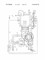
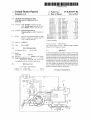
FIG. 1 illustrates a pictorial and block diagram of one
embodiment of a Water heater burner according to the present
invention; and
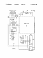
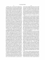
FIG. 2 illustrates a block diagram of a control portion of the
one embodiment of the Water heater burner of FIG. 1.
30
DETAILED DESCRIPTION OF THE INVENTION
35
The embodiment of the present invention described herein
is not intended to be limiting but to illustrate the principles
and the application of the invention. The present embodiment
applies corrections for both combustion air temperature and
tor signal to the controller; and a controller for receiving the
?rst and second indicator signals at respective ?rst and second
inputs and processing them according to a predetermined
relationship to provide a fan speed drive signal from a con
troller output coupled to the fan motor. In one aspect of this
embodiment the controller includes a PLC and a variable
barometric pressure to an illustrative Water heater burner
frequency drive system. In another embodiment, the control
system. As used in the folloWing description, combustion air
ler includes a PLC and a variable DC voltage drive system.
In another embodiment, a method of combustion control in
a burner is disclosed comprising the step of processing both a
?rst signal corresponding to an absolute barometric pressure
40
is the air inlet to the burner, Whether it is the ambient air at the
inlet to the burner, indoor air ducted to the burner air inlet, or
outside air ducted to the burner air inlet. HoWever, the inven
tion may be adapted to use the correction systems individu
ally for temperature or pressure or to either gas-fueled or
45
Further, While the embodiment to be described focuses on the
particular control mechanisms that may be embodied in an
illustrative Water heater system, the present invention is
measurement and a second signal corresponding to a com
bustion air temperature measurement in a controller to gen
oil-fueled burners, depending upon the particular application.
erate a variable frequency fan speed drive signal for coupling
to anAC motor, or a variable amplitude fan speed drive signal
for coupling to a DC motor, for driving an air inlet fan of the
burner. In one aspect of this embodiment, the method regu
lates the fan speed responsive to changes in the ?rst and
second signals to vary the air ?oW volume into the burner,
such that the fan speed varies inversely With changes in abso
lute barometric pressure and directly With changes in the
combustion air temperature.
In another embodiment an apparatus for controlling air
?oW into a burner responsive to parameter variations affect
ing air density is disclosed comprising: a fan motor for driv
ing an air inlet fan of the burner; a barometric pressure sensor
50
the Water heaters, Well knoWn to persons skilled in the art but
unrelated to the present invention, are not described herein.
55
for providing an electrical signal proportional to air density in
the vicinity of the burner to a controller; and a controller for
receiving the electrical signal at a control input thereof and
processing it according to a predetermined relationship to
provide a fan speed drive signal from a controller output to the
Regulating the operation of a burner involves the applica
tion of several Well-knoWn relationships for gases. The den
sity of a gas D is determined by the amount of the gas per unit
volume, or, mass/vol or, D:m/V. The Ideal Gas LaW states
that the volume of a gas is related to the temperature and
60
pressure by the formula P><V:k><T, Where Prpressure;
Vq/olume, T?emperature, and kIconstant. Restated, this
relationship is V:(k><T)+P, or, simply V (KT/P. Thus simpli
?ed, the density D<><m+(T/P), or, D<><m(P/T). In Words, den
sity is proportional to pressure and inversely proportional to
65
temperature. In a burner, to maintain an ef?cient combustion
ratio, the parameter of interest is the mass ?oW rate of the air
or the gas into the burner. Since the mass of a gas varies With
fan motor.
In yet another embodiment an apparatus for controlling air
?oW into a burner responsive to parameter variations affect
ing air density is disclosed comprising: a fan motor for driv
ing an air inlet fan of the burner; a combustion air temperature
sensor for providing an electrical signal inversely propor
readily adaptable to burners used in other applications such as
steam boilers, kilns, foundries, etc. Moreover, because the
present invention provides a control mechanism that operates
independently of the usual mechanisms found in the illustra
tive Water heating systems that utiliZe burners, many of the
structural and operating details of these usual mechanisms of
US 8,303,297 B2
6
5
The present invention, by ?ne tuning the air to fuel ratio in
its density, the mass ?oW rate of the gas (or air) varies With
barometric pressure and inversely With ambient temperature.
The present invention described herein takes advantage of
the dependence of the density of air used in a combustion
response to factors that affect the density of the air and, to a
lesser extent, the fuel in some applications, acts to prevent
instability and to maintain the excess air Within a smaller
range that is closer to the optimum value over a Wider range of
mixture With a gas or oil (liquid) fuel upon the combustion air
temperature and barometric (atmospheric) pressure of the air
temperatures and pressures. Thus, maintaining the excess air
inlet to a burner for an illustrative Water heater. This relation
Within a narroWer range results in direct energy savings and
ship, since it de?nes the effect of combustion air temperature
improved e?iciency. The present invention, as Will be appar
ent from the folloWing description, is also simple, easy to
adapt to existing systems, and is relatively loW in cost. It also
results in a smoother operating burner system and improved
and barometric pressure upon the mass of air and thereby the
mass ?oW of air inlet to the burner, enables control of the
air-fuel ratio, the ratio of the masses of the air and fuel, based
on the outputs of combustion air temperature and barometric
pressure sensors placed in the inlet side of the burner system.
To say it another Way, the system applies corrections to the air
?oW in response to variations in those attributes that Would
alter the mass ?oW rate and upset the air-fuel ratio of the
mixture into the burner. The control provides correction of the
air-fuel ratio for the changes in combustion air temperature
and pressure that may occur during normal operation of the
burner, Whether the variations take place daily or seasonally.
Not only is the air-fuel ratio held Within more e?icient limits,
longevity.
The system and method of the present invention may be
retro?tted to existing burners Without modi?cation to the
burner components. Since the system and method involves
controlii.e., electrical changes4only of the inlet air fan, it is
independent of the burner hardWare and thus does not involve
or affect the burner itself, Which operates according to its oWn
20
but the excess air is also controlled more closely to the pre
ferred range of air-fuel ratios, providing a burner system that
Will have feWer maintenance problems caused by ?ame insta
bility When operating at very high air-fuel ratios. The result is
25
more reliability and a savings of fuel and energy costs pro
vided by a more ef?cient burner. Moreover, because the con
trol reduces the fan speed, it Will also provide a savings of
electrical energy, an inherent bene?t of using a variable fre
quency drive (“VFD”) for use With AC fan motors, or a
30
is described herein.
The present invention quanti?es, as a percentage of ?oW, the
change in air density caused by the changes in combustion air
One important operating parameter of burners that is
and fuel ?oWing into the burner for e?icient combustion is
approximately 16 pounds of air for every pound of fuel con
sumed, i.e., 16 to 1. If less air is inlet to the burner for each
pound of fuel, the result is loWer heat output and the emission
of unburned fuel, representing Wasteful operation. If more
than 16 pounds of air is inlet to the burner for each pound of
35
40
resulting density changes Will correct the density change and
45
example, if the density relations indicate that the mass ?oW
change in density caused by the change in temperature.
50
air that is permitted. Normally, a range of percentages, from
about 10% to 30% is alloWed, Which accommodates a range
55
One condition that can occur if the excess air becomes too
large a percentage of the optimum mass ?oW rate of the air is
called “?ame instability.” This occurs When there is insu?i
cient fuel involved in the combustion process, i.e., an overly
lean mixture of fuel in proportion to the available air. The
adaptable to existing systems largely Without affecting the
60
unstable. An unstable ?ame may cause the burner to “huff and
puff,” as it tries to adjust to the excessive amount of air, With
very poor ef?ciency and loW or intermittent heat output. In
severe cases, the burner may shake With the uneven burning,
etc.
In practice, persons skilled in the art Will recogniZe that,
While the Ideal Gas LaW and the Fan LaWs provide the foun
dation of the control strategy embodied in the present inven
tion, some minor variations in the actual ?oW characteristics
may be noticed in real World applications. In such cases,
engineering design and experimentation are relied upon to
make needed adjustments or to compensate for these varia
tions from the ideal case. The control described herein,
because it is con?gured to affect only the fan speed, is readily
resulting ?ame is starved for fuel, making it uneven and
possibly leading to vibration and damage to burner structure,
provide a constant mass ?oW of air for combustion. For
rate is reduced 3% because of an increase in temperature, the
system can increase the fan speed by 3% to correct for the
plete burning of the fuel, resulting in an air-fuel ratio of
approximately 18 pounds of air to one pound of fuel. Thus, a
of operating conditions such as air temperature and other
parameters that affect the density of the air inlet for combus
tion, and ultimately, the air to fuel ratio.
change caused by changes in combustion air temperature and
in fan speed Will result in a proportional volume change.
Thus, changing the fan speed the same percentage as the
ine?icient operation. It turns out that some small amount of
excess airie.g., 10% to l5%iis preferred to ensure com
measure of the combustion ef?ciency is the amount of excess
temperature and barometric pressure, as de?ned by the Ideal
Gas LaW. The Fan LaWs state that, at a constant fan speed, the
air volume provided for the combustion of the fuel Will
remain the same even though the density has changed, result
ing in a mass ?oW change directly related to the density
barometric pressure. Further, the Fan LaWs state that a change
fuel, some of the energy in the fuel is used to heat the excess
air and the combustion is operating too lean, representing
system or aVSD system (also called VFDS or VSDS, respec
tively herein), all of Which are nominal cost items, to imple
ment the system.
The interface circuit or system receives the signals from the
sensing devices and processes them according to a Well
de?ned transfer function, producing a fan speed drive signal
that varies the speed of the AC motor driving the inlet air, aka
the “combustion air” fan. The fan speed drive signal may be a
variable amplitude DC voltage or a variable frequency AC
voltage, depending upon the type of motor used in the system.
variable speed drive (“VSD”) foruse With DC fan motors, that
related to the air-fuel ratio for ef?cient combustion and to the
stability of the combustion that occurs in the burner is called
“excess air.” The optimum air-fuel ratio of the masses of air
control loop. Moreover, it is loW in cost, requiring only the
addition of a temperature and/or a barometric pressure sens
ing devices, an interface circuit or system such as a VFD
65
control mechanisms already in place. Such mechanisms
include linkage or parallel positioning systems that control
the operation of valves through mechanical linkages, from
those that provide a simple ON-OFF, LOW-HIGH-LOW con
trol to those operated by multiple linkages connected to a
single actuator or to those providing continuously variable
control operated by a modulation motor. Actuators and modu
lators may be controlled by sWitches or electronics.
US 8,303,297 B2
7
8
Referring to FIG. 1, a pictorial and block diagram illus
miZe the safety and reliability of the burner. The AC motor 38
to the present invention. The Water heater system 10 includes
may be closely controlled in start/stop, speed control, ramp
ing up/doWn of the fan 36. Operating limits are also closely
a boiler 12 and a burner system 14 controlled by a controller
controlled to avoid damage or unsafe conditions. While
(or control section) 16. The illustrated boiler 12 includes a
important to the operation of the Water heater and burner
system, these functions of the control panel 68 are not rel
trates one embodiment of a Water heater system 10 according
feed Water inlet 20 and a heated Water or steam outlet 22 and
a ?ue gas outlet 24. A Water temperature sensor 26 may be
evant to the present invention and Will not be described further
herein. Thus the present invention may be implemented or
retro?tted to existing equipment at nominal co st and Without
requiring modi?cations to the system other than adding sev
eral nominal cost components and changing some of the
provided via a signal line 72 to a control panel 68 in the
controller 16. The Water in the boiler 12 is heated by a ?ring
head 3 0 Where combustion air and fuel are mixed and ignited.
The fuel is introduced into the ?ring head 30 via a pipe 32.
The inlet combustion air 34 is inducted via a fan 36 enclosed
Within the housing of the burner 14. The fan in this example is
driven by a three phase, 60 HZ AC motor 38 in the illustrative
Water heater system 10. In similar applications, the fan motor
Wiring.
38 may be a DC motor. The burner system 14 includes a
TWo sensors are provided in the controller 16 for the burner
system 14 shoWn in FIG. 1. A barometric pressure sensor 50,
including a probe 52, is installed near the burner system 14 to
measure the atmospheric pressure. In addition, a combustion
plenum portion having an inlet 40 controlling the air volume
via a damper valve 42. The damper 42 is operated by a lever
a position near the damper 42 to measure the combustion air
and linkage 84 connected to a modulator motor 80. The
burner system 14 also includes a fuel feed system that
receives fuel from a fuel supply via a pipe 90 feeding through
a fuel pressure regulating valve 92, a control valve section 94,
a fuel metering valve 88, and ultimately into the pipe 32 and
the ?ring head 30. The control valve section 94 may include
solenoid or motor-operated safety shut-off valves 96 and/or
manual valves 98 as shoWn. The fuel metering valve 88 may
be controlled by a lever and linkage 86 connected to the
air temperature sensor 54, including a probe 56, is installed in
20
ing to the measured values of the sensors. These outputs vary
betWeen 4 milliAmperes (mA) and 20 mA, according to
industry standard practice. In the illustrated embodiment, a
suitable pressure sensor is provided by a type GP311 indus
25
the 4-to-20 mA output signal current to the input of the PLC
58. A suitable temperature sensor is a resistance temperature
30
35
40
device (RTD) provided by a type T91U-2-D rangeable trans
mitter and duct sensor manufactured by Kele Inc., Bartlett,
Tenn. 38133, and WWW.kele.com.
The pressure and temperature sensor outputs are coupled
respectively via lines 60 and 62 to a circuit or circuit system
such as a PLC 58, to be processed and converted to a fan speed
signal under program control. Persons skilled in the art Will
realiZe that a specially-designed circuit could be used for the
circuit system at block 58. HoWever, a programmable logic
controller (PLC) is convenient because it is an off-the-shelf
component that can receive multiple inputs and can be pro
grammed for multiple outputs. Further, through its ability to
respond to programmed instructions, it can apply an appro
priate transfer function to the processing of the input indicator
by reducing the frequency of the AC voltage supplied to the
motor 38 from the rated 60 HZ to some loWer value. The VFD
trial grade pressure transducer manufactured by GP:50 NY
Ltd., Grand Island, N.Y. 14072, and WWW.GP50.com. This
transducer includes the sensor and a transmitter for sending
modulator motor 80. The modulator motor 80 and the valves
operated by motors or solenoids 96 may receive operating
control signals via lines connected to the control panel 68.
Continuing With FIG. 1, the control section 16 of the Water
heater system 10 Will be described. The three phase, 60 HZ AC
motor 38 that drives the fan 36 receives its three phase oper
ating voltage via the lines 44 connected to a VFD 64. The
VFD 64 is a variable frequency drive (VFD) that provides at
its output a variable frequency, three phase AC voltage for
poWering the motor 38. Motor 38 may be a three phase AC
motor that, When supplied its normal rated 60 HZ input, oper
ates at its rated speed of Mf 3500 revolutions per minute
(rpm), driving the fan 36 to deliver an air volume regulated by
the air damper 42 in cubic feet per minute into the burner
system 14. Through the VFD 64, the speed of the fan 36 may
be varied or, in this embodiment, sloWed doWn from 3 500 rpm
temperature. Both sensors 50, 54 provide direct current (DC)
electrical outputs to be used as indicator signals correspond
signals to produce the fan speed signal at the output of the
45
PLC via the line 66 coupled to the VFD 64. In the illustrative
64 in the illustrated embodiment is poWered by a three phase,
60 HZ AC supply voltage via the lines indicated by the refer
manufactured by Homer APG, LLC, Indianapolis, Ind.
ence number 72. In alternate embodiments contemplated
Within the scope of the present invention, fan motors may be
be coupled to an input of aVFD 64. The VFD 64 is a machine
con?gured for operation on single phase AC voltage or at
example, a suitable PLC device is a Part No. HE-XE105
46201, and WWW.heapg.com. The output of the PLC 58 may
50
other nominal speeds at their rated 60 HZ inputs, such as 1750
RPM, 1120 RPM, etc. In alternate embodiments contem
plated Within the scope of the present invention that employ
DC motors, the speed of the DC motor may be varied using a
variable speed drive (“VSD”) unit that varies the amplitude of
the voltage to the DC operated motor. In such applications,
55
the VSD unit Would be responsive to the same control inputs
from combustion air temperature sensors, barometric pres
input from the PLC 58 by varying the frequency of the AC
voltage to change the speed of the fan motor 38. In other
embodiments having only a single control input, such as
either temperature or barometric pressure, that control input
(sensor output) can be connected directly to the VFD 64 as
long as the signal complies With the standard 4 mA to 20 mA
60
range.
The VFD 64 is a standard off-the-shelf component that
65
provides a control method for correcting the air-fuel combus
tion ratio for changes in the ambient temperature and baro
metric pressure. As noted herein above, the How rate of the air
34 inlet to the ?ring head 30 is a direct, linear function of the
speed of the fan 36 because of the fan laW. The VFD 64 in this
sure sensors, or a programmable circuit system, as described
for the system using AC motors described in detail herein.
Returning to the illustrated embodiment, the VFD is also
coupled to the control panel 68 via the line 70 to enable it to
be responsive to other control parameters and conditions.
Line 70 is typically a cable containing numerous connections
to the control panel 68. The control panel 68 controls the
operations of the VFD 64 in response to a variety of condi
tions to provide ef?cient operation, save energy, and maxi
control to be described that is present in the AC supply circuit
to the fan motor 38. In the present invention, the VFD 64 is
utiliZed to also respond to the fan speed signal as a control
example operates from a three phase AC voltage supply via
the lines 72 and includes a recti?er, a frequency inverter, and
US 8,303,297 B2
10
a control section as internal circuitry to regulate the frequency
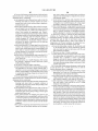
through the other side of the line 60 to a terminal labeled MA2
of the PLC 58. Similarly, a temperature sensor 54 and its
probe 56 are shoWn connected through the line 62 to the PLC
58 at terminal “L” and to the poWer supply 100 at the V+ter
minal, and through the other side of the line 62 to a terminal
of the output Waveforms generated by a pulse Width modula
tor circuit in accordance With the fan speed signal from the
PLC 58. These circuit elements Within the VFD 64, Well
understood by persons skilled in the art, Will not be further
described herein. The fan speed signal input to the VFD 64
labeled MAI. The PLC 58 is poWered by the poWer supply
100 along connections from V+ and V— respectively to ter
minals labeled L and N. The fan speed signal output from the
from the PLC 58 may be a DC current, such as a 4 mA to 20
mA current, or it may be a DC voltage varying in the range of
0 to 10 Volts DC, for example, according to industry standard
PLC 58 is coupled to the VFD 64 along the tWo Wire line 66
betWeen the PLC 58 at terminals labeled AQl and DV to the
practice.
The VFD 64 generates a variable frequency AC voltage to
drive the AC operated fan motor 38. The fan motor 38, Which
VFD at control terminals 5 (+) and 6 (—).
nominally operates at 3500 RPM (in this example) When the
AC supply voltage is 60 HZ, may be sloWed doWn by reducing
the frequency of the AC voltage generated by the VFD 64.
This variation in the AC voltage output frequency is propor
tional to the fan speed drive signal supplied by the PLC 58 and
the three phaseAC supply source and the AC supply terminals
coupled to an input of the VFD via the line 66. The VFD is a
device knoWn in the industry as a general machinery drive. In
the illustrated embodiment, the VFD may be a type ACS350
The VFD 64 is a machine control unit connected betWeen
20
manufactured by ABB Inc., NeW Berlin, Wis. 53151, and
WWW.abb.us/ drives.
In an alternative embodiment that is not illustrated herein
but Will readily occur to persons skilled in the art, the VFD 64
may be replaced by a variable speed drive (“VSD”) that
provides a direct current fan speed drive voltage for control
25
cuitry for regulating various safety and operating functions of
ling a DC operated fan motor. Substitution of a DC motor for
an AC motor does not change the present invention, is con
templated as falling Within the scope of the present invention,
and is merely a functionally equivalent choice made to satisfy
a particular application. Some burners for heating Water, or
the Water heater burner, including the fuel supply, Water tem
perature, etc. Since the present invention provides control of
30
the rest of the burner system, the control panel operation is not
The control panel is shoWn connected to a source 102 of 120
35
the PLC.
While the present invention is illustrated herein by an
embodiment having control of both the combustion air tem
perature and the barometric pres sure, other applications may
use differing embodiments, considering factors such as the
folloWing. For example, in gas burners, both the air and gas
supply pressures are referenced to the barometric pressure.
The inlet pressure to the fan is the atmospheric pressure, and
the gas pressure regulator controls to some pressure over the
atmospheric pressure. Thus, in the case of a gas burner, these
tWo pressure effects change in the same direction, and in most
cases a correction to the mass How of the air inlet is required
40
45
air Where the air has the highest density. The speed of the fan
varies linearly betWeen these tWo temperatures. These limits
50
55
are typically determined by factory settings. The factory set
tings cover all the expected temperatures of operation, the
fuel input rate and the amount of air required to completely
and e?iciently burn all of the fuel, and standard temperature
and barometric pressure for the region Where the system Will
be operating. An example of the calculation to determine the
speed of the fan motor 38 at 50° F. folloWs.
rection to the mass How of the air inlet is required for varia
tions in both the combustion air temperature and the atmo
Consider the application Where the air temperature varies
from 120° F. (condition 1) to 50° F. (condition 2), and the
spheric (i.e., barometric) pressure.
normal barometric pressure is 28.7" Hg. We Will use several
60
standard values and relations in the folloWing calculations.
They are:
burner illustrated in FIG. 1. In FIG. 2 the same reference
numbers are used to identify the same structures. FIG. 2
includes a motor speed controller comprising a ?rst section
Densityqveight of gas per volume of gas (lb/ft3 of gas at
the stated pres sure and temperature);
Std. densityIdensity of the gas at standard conditions
(PLC 58) and a second section (variable frequency drive
(VFD64)). A pressure sensor 50 and its probe 52 are shoWn
connected through the line 60 to the PLC 58 at terminal “L”
and to a poWer supply 100 at a terminal marked V+, and
vary betWeen 50° F. and 1200 E, the maximum (rated) motor
speed, Mf:3500 rpm at 60 HZ, may be set to correspond to the
maximum temperature, 120° E. (where the air has the loWest
density) and the minimum motor speed may be set to, for
example, 3077 rpm at the 50° F. temperature of the ambient
motor 38 is held constant above 120° F. and beloW 50° E, and
the regulated gas pressure. In the case of an oil burner, since
the variations in atmospheric pressure Will affect the air mass
Referring to FIG. 2, there is illustrated a block diagram of
the control portion of the embodiment of the Water heater
VFD 64 enables a simple relationship betWeen the variations
in the sensed parameters and the speed of the fan motor 38 to
be established by the control section 16. For example, in a
typical application Where the air temperature is expected to
gas burners With a vented gas pressure regulator, a slightly
?oW While the oil mass ?oW rate remains unchanged, a cor
VAC/ 60 HZ poWer that is coupled to the control panel 68 via
a line L (104) and a line N (108). The line L (104) includes a
5 Amp fuse 106.
The linear speed control characteristic provided by the
only for variations in the ambient temperature. HoWever, in
modi?ed correlation may be required because the barometric
pressure change Will also change the gas pressure. The cor
rection adjustment may be made in the PLC 58 by referencing
the inlet air by regulating the inlet fan speed independently of
relevant to describing the operation of the present invention.
used in other systems may utilize a DC motor as ef?ciently as
an AC motor. In such applications, a variable speed drive or
VSD is substituted for the VFD. AVSD may be con?gured to
be responsive to a DC fan speed signal output to the VSD by
of the fan motor 38. Thus, the L1 line in cable 72 connects to
terminal U1 of the VFD 64 and terminal U2 of the VFD 64
connects to an L1 terminal of the fan motor 38. Similarly, line
L2 from the source connects via cable 72 through terminals
V1, V2 to an L2 terminal of the fan motor 38 and an L3 line
in cable 72 connects through terminals W1, W2 to an L3
terminal of the fan motor 38. A ground connection from
terminal PE of the VFD 64 is provided on the AC source side
and a ground connection from the terminal PE on the output
of the VFD 64 is provided to the frame of the fan motor 38.
The cable 44 from the VFD 64 may be shielded, With the
shield connected to the PE terminal of the VFD 64. The
control panel 68 shoWn in FIG. 2 includes substantial cir
65
(0.0765 lb/ft3 for air at 60° F. and 29.92" Hg);
Absolute pressureIgauge pressure+barometric pressure of
the current condition;
US 8,303,297 B2
11
12
Std pressureIstandard pressure, 29.92" Hg (barometric
mA analog control input to the VFD 64 is available. The VFD
pressure);
device generally has this capability through its built-in single
Std temperatureIstandard temperature, 60° F.; and
loop controller to convert the DC control input to the fan
speed control signal. This particular embodiment thus does
Absolute temperature:460+° F. of the gas.
Based on the known fuel input, the burner requires 10,000
pounds per hour of air to completely and ef?ciently burner all
not require any programming and Would be transparent to the
start-up technician and in use. Persons skilled in the art Will
of the fuel provided by the burner. The following analysis
readily be able to adapt the invention to their speci?c system
based on the description provided in the foregoing example.
Would be used to generate the control strategy.
The densities of the air at the tWo conditions are (from Eqn.
Other applications of the present invention include a
simple pres sure control package for burners that again utiliZes
the single loop controller of the VFD 64 and a barometric
1);
Density
sensor such as the sensor 50 and probe 52 combination
described herein above. The process for con?guring the sys
tem is similar, based on initial conditions de?ned for tWo
different air densities and the corresponding fan outputs
Density 2:0.0765x(28.7/29.92)><(460+60)/(460+50):
(ACFMl and ACFM2) calculated from: (amount of air
required, in 1b., for the given amount of fuel)+(air density, in
0.07482 lb/cu?
The required fan output for each condition Will be, using
lb./cu. ft.) for each of the tWo conditions. For a hypothetical
Fan Actual Cubic Feet per Minute (ACFM):
20
ACFMl:10,000/(0.06579><60):2533 CFM
ACFM2:10,000/(0.07482><60):2228 CFM
Where the values are;
25
Lb air/hFpounds of air required per hour (as stated in this
example);
essary to maintain the correct CFM must be reduced.
Standard air density:0.0765 lb/ft3 ;
Standard air pressure:29.92" Hg;
Local air pressure:28.7" Hg;
30
Air temperature at condition 1:120° F.;
Air temperature at condition 2:50o F.; and
RPM:revolutions per minute.
The burner Was setup under condition #1 at 120° F., Which
is the loWest air density. The combustion air motor and fan are
35
can be combined in the folloWing manner, Wherein the cal
both types of sensors. Correction factors for the ambient air
temperature and the barometric pressure are de?ned as fol
loWs:
completely burn the fuel and some minimal amount of excess
air, for good combustion e?iciency.
40
K7;(460+Tair)/(460+Tmax); and
air (based on fan laWs), and since the density is much higher
(more pounds of air per volume at this loWer air temperature)
KP :BploW/BPair.
the burner Would normally have much more air then needed
for combustion. A higher excess air rate Would result in loWer
combustion e?iciency. The system of the present invention
Will change the fan speed to match the changes in air tem
In another application of the present invention for Water
heaters, both combustion air temperature and barometric
pressure corrections canbe implemented. The system is much
like the illustrated embodiment described herein above. From
the previous examples of single control elements, the correc
tion for air temperature and pressure has been de?ned. They
culations are performed in the PLC responsive to inputs from
operating at 3500 RPM and the air damper is adjusted to
generate a How of 2533 CFM, Which provided enough air to
At condition #2, the fan Will generate the same volume of
atmospheric pressure range of 27.7 in. (condition 1) to 29.7
in. (condition 2), a temperature of 85° F. and 10,000 lb. of air
required to burn the fuel, ACFMII2466 CFM and
ACFM2:2300 CFM. At condition 1, the RPM, is set to 3500
RPM for apressure of 29.7 in. Then RPM2 is determined by:
RPM2:3500 (2300+2466):3264 RPM. Notice in this
example that the highest fan speed is set to the loWer pressure
boundary, Where the density of the air is loWer. As the pres sure
rises, the density of the air increases, and the fan speed nec
Thus, the fan speed is determined by:
45
Speed:3500 RPMXKTXKP,
Where,
perature, and provide the same mass of air to the burner ?ring
head 30. The neW fan speed required to obtain a volume How
of 2228 CFM is,
50
KTITemperature correction factor (dimensionless);
KPIBarOmetric pressure correction factor (dimensionless);
BPal-Fcurrent barometric pressure, Hg, in.;
BPZOWIlOWest barometric pressure, Hg, in.;
TaiFcurrent air temperature, ° F.;
Tairmax?he highest expected combustion air temperature °
= (3500 RPM) >< (2228/2533)
: 3077 RPM
F.; and
55
SpeedIcontrolled RPM of the combustion air fan motor.
These calculations provide a set of relationshipsiWhich
may be represented by a family of characteristic curves, if
plotted (i.e., one curve for each increment of barometric pres
60
Where the different barometric pressures Would be identi?ed
65
With multiple lines. These operations Would be performed on
a continuous manner, Where the fan speed drive signal is
alWays calculated and delivered to the VFD, and the fan
alWays operates at the correct speed for the operating condi
tions. When the unit is initially setup, it Will be calibrated to
Where,
RPM1:RPM at condition 1, and RPM2:RPM at condition
2.
sure, When the axes are motor speed vs. combustion air)i
The foregoing example illustrates an application of the
present invention to a Water heater bumer system Wherein the
combustion air temperature alone is used as a control param
eter to vary the speed of the fan motor 38. This example is
simple and loW cost, making it especially adaptable to smaller
bumers With loWer fuel costs and loWer payback opportunity.
the correct mass ?oW, as measured by a combustion analysis
In this application, the PLC is not needed because the 4 to 20
performed at startup.
US 8,303,297 B2
14
13
Maximum air temperature:maximum expected air tem
The foregoing are just a feW of the examples of combustion
control through applying measurements of temperature and
perature ° F.; and
pressure of the ingredients of the combustion process. Other
potential applications include controls based on: gas fuel
temperature; combined fuel temperature, combustion air
temperature and barometric pressure; and outside ducted
combustion air temperature. Any combination of combustion
air temperatures, barometric pressure, gas fuel temperature
and gas fuel pressure can be used by applying the Ideal Gas
LaW and the Fan LaWs.
Absolute temperature of air:(460+air temperature ° F.).
A PLC is required to combine the readings of the pressure
sensor and offset according the above (equation 6). This
Would be converted to a 4-20 mA signal that can be used by
the single loop controller in the VFD, Which Will vary the
combustion air motor speed to maintain the desired set point
pressure.
While the invention is described in only several of its
forms, it is not thus limited but is susceptible to various
The present invention may even be used to correct the fan
speed in a burner system that already uses a variable speed
changes and modi?cations Without departing from the spirit
control to maintain a constant pressure at the air inlet of the
thereof. In the illustrative example, the control system is an
electrical or electronic device, Which is a typical implemen
tation of machine control systems. In some electrically-based
systems, substitutions may be made. For example, the PLC
and/or the VFD or VSD may be replaced by a circuit speci?
cally designed to process the sensor outputs and generate the
burner, betWeen the air damper and the fan. In such a variable
motor speed control system, a pressure sensor is located
betWeen the air damper and fan inlet to measure the pres sure
at that location. A single loop controller reads this pressure
and is programmed to maintain a constant pressure, typically
around —2.0" we (inches of Water columr). Note, for refer
particular kind of control or “fan speed signal.” Further, other
ence, 27.7" we in a tube:l .0 pounds per square inch (“psi”).
As the air damper opens, the pressure drops, and the control
20
As the air damper opens, increasing the air supply to the
burner, the ?ring rate is alloWed to increase. If the air damper
mass ?oW rate of air inlet to a burner Within an optimum range
is located on the outlet side of the fan, the pressure Will be
positive instead of negative. This system has been used in
for high e?iciency. In other systems, the control outputs may
25
many applications over the years. Typically, the motor Will
vary from about 1000 RPM at loW ?re up to 3500 RPM at high
?re. The electrical use at the loWer ?ring rates is considerably
loWer than the standard burner, and results in a signi?cant
electrical savings. Rebates from electric companies may be
available for these applications.
What is claimed is:
30
adjustment device, comprising:
speed systems,” Where the fan speed is controlled over a large
a barometric pressure sensor disposed near said air inlet for
35
proportional thereto; and
substantial gains in e?iciency can be realiZed by varying the
fan motor speed over a narroWer range, such as 2800 to 3500
40
air inlet of said burner system to a ?rst electrical signal
and a second section for converting said ?rst electrical
To combine the electrical savings of the standard variable
45
the application of the air temperature adjustment Would be
accomplished using a “square laW” that says the ratio of
pressures equals the ratio of the ?oWs squared, or
Where,
PZINeW pressure set point betWeen the air damper and fan;
P1:Original pressure set point betWeen the air damper and
55
60
Where,
Tairmax?he highest expected combustion air temperature
° F.;
2. The device of claim 1, Wherein:
said ?rst section is a programmable logic controller (PLC)
having at least a ?rst input for receiving said ?rst elec
trical signal; and
The ratio of old to neW air How is represents the volume air
?oW rate change required to maintain the same mass ?oW rate
of the burner, Which can be determined directly from the
TairIcurrent air temperature, ° F.;
speed of said variable speed motor corresponding to said
minor daily or seasonal variations in atmospheric pres
sure, thereby adjusting for variations in said inlet air
density.
fan, —2.0" Wc;
temperature change as done in the described embodiment,
With the ?nal form of:
signal to a variable frequency AC voltage signal accord
ing to a second relationship SIKPXMf rpm, Where
SIspeed of said motor, MfIspeed of said motor at 60 HZ,
and rpm:revolutions per minute; and
a cable connecting saidAC voltage signal from said second
section to AC terminals of said motor for adjusting said
50
ACFMIIair ?oW rate before temperature change; and
ACFMZIair ?oW rate required after temperature changes.
ing said signal from said barometric pressure sensor
according to a ?rst relationship KP:PB(min)+PB(air),
Where PB(min):minimum barometric pressure, and
PB(air):current barometric pres sure measured near said
With corresponding improvements in ef?ciency and reduced
operating costs.
control of the illustrated embodiment described herein above,
detecting minor daily or seasonal variations in atmo
spheric pressure near said air inlet and providing a signal
a motor speed controller having a ?rst section for convert
directed to and contemplated for use With systems in Which
speed motor control With, for example, the air temperature
1. For use With a burner system having an air inlet and an air
inlet fan driven by a variable speed motor, an inlet air density
speed range, e.g., 1000 RPM to 3500 RPM, control based on
temperature offers true savings. This is also true for combined
RPM. Nevertheless, the principles of the present invention
may readily be applied to control of the Wider range of speeds,
be derived from sensors that detect variations in fuel param
eters and adjust the inlet air How to maintain a predetermined
combustion ef?ciency and performance.
In some applications, knoWn as so-called “true variable
sensing, such as temperature and pressure, yielding improved
ef?ciency and savings. The present invention is primarily
systems may be more amenable to control systems based on
hydraulic or pneumatic circuits for sensing operating param
eters and generating corresponding outputs to maintain the
Will increase the fan motor speed to maintain the set pressure.
65
said second section is a variable frequency drive system
that includes a frequency inverter circuit and a pulse
Width modulator circuit.
3. The device of claim 1, further comprising:
a transfer function formed of ?rst and second relationships
and embedded in said motor speed controller that is
operable to convert a percentage change in said inlet air
density corresponding to said barometric pressure sen
sor output to an equivalent percentage change in said
speed of said variable speed motor.
US 8,303,297 B2
15
16
ture sensor outputs and converting them according to
respective ?rst relationships to respective ?rst and sec
4. For use With a burner system having an air inlet and an air
inlet fan driven by a variable speed motor, an inlet air density
ond electrical signals;
adjustment device, comprising:
a second section for receiving said respective ?rst and
second electrical signals from said ?rst section and con
verting them to an variable frequency AC voltage signal
an air temperature sensor disposed near said air inlet for
detecting minor daily or seasonal variations in air tem
perature near said air inlet and providing a signal pro
according to respective second relationships; and
portional thereto; and
a cable connecting saidAC voltage signal from said second
a motor speed controller having a ?rst section for convert
section to AC terminals of said motor to adjust the speed
of said variable speed motor corresponding to said minor
daily or seasonal variations in atmospheric pressure,
ing said signal from said temperature sensor according
to a ?rst relationship KT:(460+T(21i1‘))+(460+T(II121X)),
Where T(air):current air temperature, and T(max):
thereby adjusting for variations in said inlet air density.
maximum air temperature measured near said air inlet of
said burner system to a ?rst electrical signal and a second
section for converting said ?rst electrical signal to a
8. The device of claim 7, Wherein said ?rst relationships
comprise KP:PB(min)+PB(air), Where PB(min):minimum
barometric pressure, and P(air) current barometric pressure
measured near said air inlet of said burner system, and
variable frequency AC voltage signal according, to a
second relationship S TIKIXMfI‘Pm, Where S TIspeed of
said motor, MfIspeed of said motor at 60 HZ, and rpm
revolutions per minute; and
a cable connecting saidAC voltage signal from said second
KT:(460+T(air))+(460+T(max)), Where T(air):current air
temperature, and T(max):maximum air temperature mea
sured near said air inlet of said burner system; and
said second relationships comprise SPIKPXMf rpm, and
section to AC terminals of said motor for adjusting said
S TIKIXMfI‘Pm Where SP and ST respectively:speed of
speed of said variable speed motor corresponding to said
said motor and MfIspeed of said motor at 60 HZ, and
rpm revolutions per minute.
9. The device of claim 7, further comprising:
minor daily or seasonal variations in air temperature,
thereby adjusting, for variations in said inlet air density.
5. The device of claim 4, Wherein:
said ?rst section is a programmable logic controller (PLC)
having at least a ?rst input for receiving said ?rst elec
25
tive relationships and embedded in said motor speed
controller that is operable to convert a percentage
trical signal; and
said second section is a variable frequency drive system
that includes a frequency inverter circuit and a pulse
Width modulator circuit.
change in said inlet air density corresponding to said
barometric pressure and air temperature sensor outputs
30
6. The device of claim 4, further comprising:
a transfer function formed of ?rst and second relationships
and embedded in said motor speed controller that is
operable to convert a percentage change in said inlet air
density corresponding to said temperature sensor output
to an equivalent percentage change in said speed of said
variable speed motor.
density adjustment device, comprising:
35
7. For use With a burner system having an air inlet and an air
a sensor disposed near said air inlet and providing a signal
proportional to at least one of barometric pressure and
air temperature at an output of said sensor;
a motor speed controller coupled at an output thereof to AC
voltage terminals of said motor and having an input of
said controller coupled to said output of said sensor;
a cable connecting a variable frequency AC voltage signal
from said output of said controller to said AC voltage
adjustment device comprising:
a barometric pressure sensor disposed near said air inlet for
detecting said minor daily or seasonal variations in
atmospheric pressure near said air inlet providing a ?rst
terminals of said motor and
a transfer function embedded in said motor speed control
signal proportional thereto;
ler that is operable according to a ?rst relationship (ratio
an air temperature sensor disposed near said air inlet for
of a reference barometric pressure or air temperature and
a current value near said air inlet) and a second relation
detecting said minor daily or seasonal variations in air
temperature near said air inlet providing a second signal
ship (product of said ratio and rated motor speed) cal
culated respectively in ?rst and second sections of said
motor speed controller to convert a percentage change in
said inlet air density corresponding to an output of said
sensor to an equivalent percentage change in said speed
proportional thereto; and
a motor speed controller for adjusting the speed of said
variable speed motor corresponding to said minor daily
or seasonal variations in said atmospheric pressure and
temperature, thereby adjusting for variations in said inlet
air density; Wherein said motor speed controller further
comprises:
to an equivalent percentage change in said speed of said
variable speed motor.
10. For use With a burner system having an air inlet and an
air inlet fan driven by a variable speed motor, an inlet air
inlet fan driven by a variable speed motor, an inlet air density
a ?rst section for receiving said respective ?rst and second
signals from said barometric pressure and air tempera
a transfer function formed of said ?rst and second respec
of said variable speed motor, thereby correcting said air
inlet density for minor daily and seasonal variations in
55
an atmospheric, condition sensed by said sensor.
*
*
*
*
*