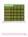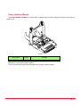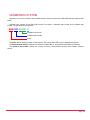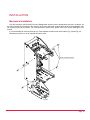
1
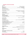
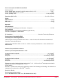
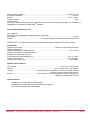
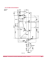
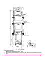
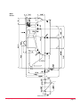
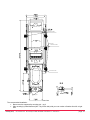
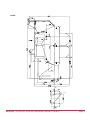
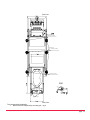
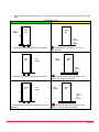
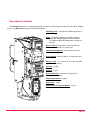
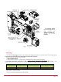
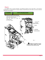
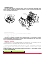
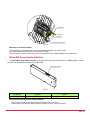
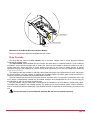
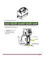
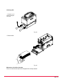
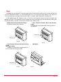
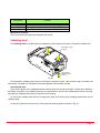
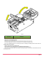
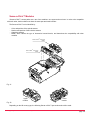
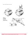
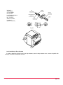
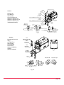
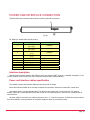
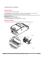
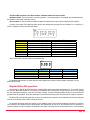
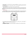
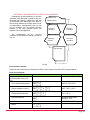
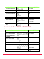
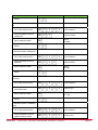
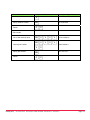
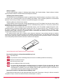
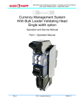
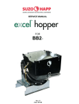
Bill-to-Bill Currency Management System Operation and Service Manual Part 1. Operation Manual Revision – J of July 28, 2011 Suzo-Happ Group 1743 Linneman Road [email protected] Mount Prospect, IL 60056 USA PHONE: 1-847-952-5932 or 1-800-239-7017 page. 1 Table of Contents General description General specifications Outline drawings Description of modules Housing Chassis Recycling Cassette Dispensing Cassette Path Switch Bill-to-Bill Power Interface Module Drop Cassette Bezel Validating head Sense-a-Click™ Modules Power Interface Module Numbering system Installation Mechanical installation Security features (locks and security switches) Power and interface connection Interface description Power and Interface cables specification Operating control Default settings DIP Switch settings Regular Bill-to-Bill operation Possible Errors during operation Application settings Inquiries about the Bill-to-bill settings and status Inquiries about software VERSION and PART NUMBER Contact: Suzo-Happ Group 1743 Linneman Road Mount Prospect, IL 60056 USA PHONE: 1-847-952-5932 or 1-800-239-7017 3 4 7 14 15 16 17 19 21 22 23 26 27 29 31 32 33 33 35 41 41 41 42 42 42 43 44 44 49 50 56 page. 2 GENERAL DESCRIPTION The Bill-to-Bill Currency Management System is an automatic money-handling device that provides the following features: 1) Validating bills (any country, sizes as specified). Validated bills are distributed between three recycling cassettes and one lockable-removable drop cassette. A maximum of three denominations may be directed to the recycling cassettes, while the rest of the bill denominations will be directed to the drop cassette. 2) Dispensing bills. Bills housed in the recycling cassettes can be bundled and dispensed as change to a customer (up to twenty bills at a time). 3) Unloading bills. Bills from the recycling cassettes can be moved into the drop cassette. The Bill-to-Bill can be programmed to operate in different modes. For example, bill denominations may be designated for each recycling cassette; choice of escrow settings may be specified, etc. Suzo-Happ Group 1743 Linneman Road Mount Prospect, IL 60056 USA PHONE: 1-847-952-5932 or 1-800-239-7017 page. 3 GENERAL SPECIFICATIONS Acceptance: Bills………..………………………………….……………..................................…………lengthwise in 4 directions Barcoded coupons…......………………………………………..............................……..………..two ways, face up Validation rate………………………………….…..................................………96% or higher on first bill insertion Width of bill, in mm…………………………..................................……………………..………………from 62 to 82 Maximum length of bill, in mm…………….................................………………………..………………………..172 Minimum length of bill, in mm………….................................……………………………………………………..124 Barcoded Coupon Specifications: Encoding standard………………………….…….............................….ANSI/AIM BC2-1995, Uniform Symbology Specification – Interleaved 2 of 5 Narrow bar width, in mm………………………..............................……..…….………………………..…..0.5 to 0.6 Wide/Narrow bar ratio………………………….............................…………….……………………….…………..3:1 Number of characters…………………………………….............................….…………………….…………6 to 18 PSC (Print Contrast Signal) value ………………………..................................……………………..………0.6 min Bill storage: Number of recycling cassettes……………………………….............................…………………………………….3 Number of drop cassettes…………………………………….............................…………………………………….1 Recycling cassette capacity.………….….................................……….…80 to 110 bills depending on bill length Drop cassette capacity (new bills)……………................................……………………………………….1000 bills Dispensing ability………………………………………..……...............................bundles up to 20 bills at a time Multi-escrow mode Single dispensing…………………………….……………….……………..….............................……..up to 20 bills Several dispensing attempts……….......................................………up to 80 - 110 bills depending on bill length Processing time, in seconds: Time of identification (from bill insertion to credit issue)………................................…………..……………….2.5 Time between two entered bills……………………………………………................................……..….. 3.5 to 4.5 Total time to accept one bill to recycling cassette…………………………..……...............................…. 3.5 to 4.5 Total time to accept one bill to drop cassette………………………………………….............................. 3.5 to 6 Total time to issue change of 1 bill……….……………………………………………………..................................3 Total time to issue change of 20 bills ………..……………...……………….............................………………… 26 Dispensing speed………………………………..………..............................…...….……1.4 second per bill, max. Firmware updates options: Standard…………………………....……….……………….……….......... Crane Payment Solutions Memory Stick Network….………………..............................……... Download mode in CCNET protocol or in the service mode External Interfaces: Standard…………………………....……….…….…...............................……..…Bi-directional EIA-232C (RS232) Protocol….…………………………………….…………………...………………... CCNET Power consumption for B2B with plastic Bezel Operating voltage……………………………….....…………..........................………….……………..…… 24 V DC Current, standby………………………………………….…………….............................……………..………..0.6 A Current, operating mode………………………………………………….…................................…2.4 A (4 A peak) Suzo-Happ Group 1743 Linneman Road Mount Prospect, IL 60056 USA PHONE: 1-847-952-5932 or 1-800-239-7017 page. 4 Power consumption for B2B with metal Bezel Operating voltage……………………………….....…………..........................………….……………..…… 24 V DC Current, standby, peak, unit at 0C to +50C, bezels at -30C to +5C ..........................………..………..2.2 A Current, standby, bezels at +5C to +60C ………………….……………....................……………..………..0.6 A Current, operating mode………………………………………………….…................................…2.4 A (4 A peak) Dimensions (W x H x D)………………………….....……………….............................……..163 x 569 x 378 mm Weight B2B plastic bezel..………………...............................……..…..…………………………………….….……. 17.2 kg B2B metal bezel..…….……………….…...............................…………………………………………..……. 18.2 kg B2B loader……....………….…………….…………..............................…………………...………….………17.8 kg Approvals: Safety Standards for Coin and Currency Changers and Actuators - Component……………...............................…………..UL 756 FCC Compliance Radiated Emissions from Unintentional Radiators (digital devices) FCC Part 15, Subpart B 15.109a Class B CE Compliance………………………………………..............................……Information Technology Equipment Electromagnetic Compatibility (EMC) Conformity to the Following Standards: CISPR 22:2003 +A1:2004 / EN 55022:2003 Class A - Class A Limits for RF disturbance characteristics of Information Technology Equipment CISPR 24:1997 / EN 55024:1998 +A1:2001 & + A2:2003 Immunity Characteristics – Limits and Methods of Measurements Vibrations, Drop and Shock resistance: Vibrations (sinusoidal) IEC 60068-2-6 Fc: 1995 vibration acceleration amplitude………...........................…………………………………………….. а= 12 m/sec2 bandwidth……………………………………………………..............................……………………. F = 10...200 Hz sweep rate……………………………………………………………..................................... one octave per minute vibration acceleration amplitude ………………………………………………….........................… а= 19,8 m/sec2 bandwidth……………………………………………………….............................…………………. F = 10... 500 Hz sweep rate………………………………………………….................................…………… one octave per minute Endurance at random vibration wide band testing within F = 10. . .200 Hz at 12 m/s2 mean-square acceleration amplitude and number of loading cycles n = 10 е-7 Control method: Bill-to-BillTM operation was continuously controlled by means of the bill loading and unloading. No malfunction or stoppages were registered in the Bill-to-BillTM operation. Mechanical Shocks Shock endurance at shock testing (Shock: IEC 60068-2-27 Ea: 1987; Bump: IEC 60068-2-29 Eb: 1987): Suzo-Happ Group 1743 Linneman Road Mount Prospect, IL 60056 USA PHONE: 1-847-952-5932 or 1-800-239-7017 page. 5 shock repetition frequency……………………………………..............................………..……. F = 80 shock / min acceleration amplitude ………………………………………………...............................……………………30 m/s2 duration ………………………………………………………………..…………................................Т=10...12 msec number of shocks………………………………………………………………….............................……………2000 Control method: Bill-to-BillTM operation was continuously controlled by means of the bill loading and unloading. No malfunction or stoppages were registered in the Bill-to-BillTM operation. Free Fall IEC 60068-2-32 Ed: 1975 Test Conditions: Bill to Bill Currency Management System tested as a whole unit. Drop height ………………………..……………………………….............................……..…………………..50 mm Surface………………………...............................……3 mm thick steel plate on wood bed at 20C and 58% RH The Bill-to-BillTM survived the test free from any serious complications and preserved its full functionality. Environment: Operating environment…..…………….............................……...……………Indoor or environmentally protected stationary applications Operating Temperature for Bill-to-Bill unit……………….............................…………..……………..0C to +50C Operating Temperature for metal bezels with heating element (Bill-to-Bill unit to be in the temperature range stated above)…………………………..............................……………..-30C to + 60C Storage Temperature……………………………………………….............................…………..…-30C to +60C Humidity (non-condensing)………………………….............................……………….……..………..30%-90%RH Optional security features: Drop cassette……………………………………….................................………………one or two ¾” tubular locks Housing………………………………………….................................…….…one ¾” tubular lock for drop cassette Housing……………..............................………2 security switches to signal alarm when drop cassette unlocked or removed; chassis unlocked and removed Chassis…….................................……………..one ¾” tubular lock for locking chassis, recycling cassettes and dispensing cassette inside housing Optional features: Vandalism-proof metal bezel for validating head Vandalism-proof metal bezel with heating element for dispenser Drop cassette equipped with Cash Manager Suzo-Happ Group 1743 Linneman Road Mount Prospect, IL 60056 USA PHONE: 1-847-952-5932 or 1-800-239-7017 page. 6 OUTLINE DRAWINGS Standard Bezels Side view Suzo-Happ Group 1743 Linneman Road Mount Prospect, IL 60056 USA PHONE: 1-847-952-5932 or 1-800-239-7017 page. 7 Screw M5, Pan Head Mounting pins Screw M5, Pan Head Screw M5, Pan Head B-B B B Mounting pins Front view The recommended installation: Bottom must be supported by mounting pin – qty 2 Side mounting by metal fasteners (M5 – Qty 3 each side) with your own version of bracket from left or right side Suzo-Happ Group 1743 Linneman Road Mount Prospect, IL 60056 USA PHONE: 1-847-952-5932 or 1-800-239-7017 page. 8 Metal Bezels Mounting holes A A Mounting holes Side view Suzo-Happ Group 1743 Linneman Road Mount Prospect, IL 60056 USA PHONE: 1-847-952-5932 or 1-800-239-7017 page. 9 Screw M5, Pan Head Mounting pins Screw M5, Pan Head Screw M5, Pan Head B-B B B Mounting pins Front view The recommended installation: Bottom must be supported by mounting pin – qty 2 Side mounting by metal fasteners (M5 – Qty 3 each side) with your own version of bracket from left or right side Suzo-Happ Group 1743 Linneman Road Mount Prospect, IL 60056 USA PHONE: 1-847-952-5932 or 1-800-239-7017 page. 10 Loader Mounting holes A A Mounting holes Suzo-Happ Group 1743 Linneman Road Mount Prospect, IL 60056 USA PHONE: 1-847-952-5932 or 1-800-239-7017 page. 11 Side view Screw M5, Pan Head Mounting pins Screw M5, Pan Head Screw M5, Pan Head B-B B B Mounting pins Front view The recommended installation: Bottom must be supported by mounting pin – qty 2 Suzo-Happ Group 1743 Linneman Road Mount Prospect, IL 60056 USA PHONE: 1-847-952-5932 or 1-800-239-7017 page. 12 Side mounting by metal fasteners (M5 – Qty 3 each side) with your own version of bracket from left or right side Installation View GOOD Installation Side Bracket Poor Installation Bill to Bill Bill to Bill Base plate on the bottom √ Side Mounting and Mounting Pin on the bottom Bill to Bill Side Bracket Flat base plate on the bottom. This is not recommended Bill to Bill Side Bracket Base plate on the bottom √ Side Mounting and Mounting Pin on the bottom Bill to Bill Side Bracket Side Mounting and flat base plate on the bottom. This is not recommended Side Bracket Bill to Bill Base plate on the bottom √ Side Mounting on Both Side and Mounting Pin on the bottom Suzo-Happ Group 1743 Linneman Road Side Mounting and flat base plate on the bottom. This is not all recommended Mount Prospect, IL 60056 USA PHONE: 1-847-952-5932 or 1-800-239-7017 page. 13 Description of modules The Bill-to-Bill was built on modularity principles, just like the Crane Payment Solutions FrontLoad bill validator product. The Bill-to-Bill consists of the following modules: Validating Head – accepts and validates legitimacy of bill Bezel – Six different bezels are available—however, bezels with a digital display are recommended (for Software update and diagnostics via a service keypad) Sense-a-Click™ sensor pack – Four versionas are available depending on currency set Power Interface Module - Only one variety may be used with the B2B Drop Cassette - Secure Cashbox, it is referred to as a “cassette” Memory Card - is universal for all Crane Payment Solutions products Housing – 2 types Chassis – 1 type Recycling Module – Consists of a total of three recycling cassettes Dispensing Cassette – 2 types Path Switch – 1 type Bill-to-Bill Power Interface Module – 1 type Suzo-Happ Group 1743 Linneman Road Mount Prospect, IL 60056 USA PHONE: 1-847-952-5932 or 1-800-239-7017 page. 14 Sense-a-Click Memory Card Validating Head MFL B2B Power Interface Module Validating Head with Loader Bezel Dispensing Cassette Housing All modules (except for the housing) can be easy removed and replaced if needed (i.e.: should a bill become jammed). MFL Power Interface Recycling Cassette (3 pcs.) Chassis Path Switch Drop Cassette Fig. 2 Housing The Bill-to-Bill housing carries all of the modules and cables necessary for interconnections. The housing is the only module in the Bill-to-Bill that is permanently installed inside a cabinet. There are security switches in the housing: 1. “drop cassette removal”, 2. “drop cassette lock open”, (if the locking mechanism for the drop cassette is present), For switch connection, please refer to the “INSTALLATION. SECURITY FEATURES”. Depending on the supporting bracket for the drop cassette, the following implementations of the housing are available: Bezels Plastic Metal Plastic Part Number BBHR3110 BBHR3513 BBHR3514 Drop Cassette size 1000 1000 1000 Locking mechanism NO YES YES Maintenance of the Housing. There is no procedure designated for this module. Suzo-Happ Group 1743 Linneman Road Mount Prospect, IL 60056 USA PHONE: 1-847-952-5932 or 1-800-239-7017 page. 15 Chassis The chassis carries 3 recycling cassettes, one dispensing cassette, and one path switch. It also has drive arrangements—for transporting bills, recycling cassettes, and positioning the path switch—as well as connection cables and a local controller. Part Number BBCR0110 Number of Recycling Cassettes 3 Removing the Chassis from the Housing Unlock the tubular lock at the front of the dispensing module (if present) Push the release bar under the validating head Pull out the chassis 1. PUSH THE BAR TO RELEASE THE CHASSIS HANDLE 2. PULL OUT THE CHASSIS USING THE HANDLE Fig. 3 Caution! The chassis may be heavy to handle! Support the module beneath the chassis with one hand. Suzo-Happ Group 1743 Linneman Road Mount Prospect, IL 60056 USA PHONE: 1-847-952-5932 or 1-800-239-7017 page. 16 Accessing the Bill Path: Press either release button and pull open the machine. The gas spring supports the chassis in the opened position. The opened chassis also allows access to the path switch. The chassis can be opened with, or without, the recycling and dispensing cassettes present. Path Switch Push release button to open the Chassis Optical sensors Fig. 5 Fig. 6 Maintenance of the Chassis The maintenance of the chassis is recommended approximately two times per year. The preventative maintenance includes: visual inspection of timing belts visual inspection of gears visual inspection of optical sensors There must not be any cracks on the surface of the four timing belts; no dust or dirt on the surface of the optical sensors (6 sensors at each guide, for a total of 24 sensors), and no visible damage of the gears. Optical sensors should be cleaned with a soft cloth and isopropyl alcohol. Recycling Cassette The Bill-to-Bill carries up to three recycling cassettes, which operate identically. Built with flexibility in mind, the user can program which bill denominations will be used in each of the recycling cassettes. The maximum storage capacity of each cassette ranges from 80 to 110 bills. The exact number of bills that can be stored is dependent upon the bill length: the shorter the bill, the higher the number of bills that can be placed inside the cassette. A flash memory inside each recycling cassette stores information on the number, and denomination of bills housed in the cassette. The flash memory prevents operation errors from occurring, i.e.: when a cassette is installed in a random position in the Bill-to-Bill. Part Number BBRR0110 Suzo-Happ Group 1743 Linneman Road Bill storage capacity 80 - 110 Mount Prospect, IL 60056 USA PHONE: 1-847-952-5932 or 1-800-239-7017 page. 17 Removing the Cassette: Remove the chassis from the Bill-to-Bill housing first (see section entitled “chassis”) Slide the latch on the chassis (each cassette has its own latch) and pull out the cassette Slide the latch Pull out the Cassette Fig. 8 Fig. 7 Opening the Cassette: Pull the metal latch, and open the front cover of the cassette. Open the cover Plastic handle Pull the latch Fig. 9 Fig. 10 Manually Unloading Cassettes: Rotate the plastic knob in counter-clockwise direction. Bills are manually dispensed one bill at a time. Should a jammed bill be located in the entrance slot, this bill can be easily removed without adversely affecting the later operation of the cassette. Please note: manually unloading bills will reduce the number of bills in the cassette, without changing the number of bills in flash memory. It is strongly recommended to perform a complete unload Suzo-Happ Group 1743 Linneman Road Mount Prospect, IL 60056 USA PHONE: 1-847-952-5932 or 1-800-239-7017 page. 18 operation, after the cassette is replaced in the Bill-to-Bill (please see the “Unloading Options” section). This will allow the Bill-to-Bill to readjust the flash memory when the cassette is operational again. Caution. Do not attempt to pull out the white tapes present in the cassette! This could damage the cassette! Maintenance of the Recycling Cassette The maintenance is recommended approximately two times per yearand includes: - visual inspection of tapes - visual inspection of input optical sensors A mechanism within the cassette keeps the tapes tight at all times, which provides sufficient support for stored bills. Should any tape begin to sag, this can be easily corrected during service by simply rotating the plastic knob on the cassette in any direction. This action will cause the mechanism inside the cassette to retighten. For optimal performance, there must not be any dust or dirt on the surface of the input optical sensors. (There are two sensors at each side of the entrance slot, for a total of four sensors.) Input optical sensors may be cleaned with a soft cloth and isopropyl alcohol once the front cover is open. Dispensing Cassette There is only one dispensing cassette in the Bill-to-Bill unit. In contrast to the three recycling cassettes, the dispensing cassette has a permanent position in the chassis. The dispensing cassette can form a bundle of up to 20 bills. Bills from all three recycling cassettes can be combined into one bundle. Should more than 20 bills need to be dispensed, then subsequent bundles will be delivered to the dispensing cassette once the previous bundle is removed. Slide the latch to open Entering slot Plastic handle Service keypad Dispensing slot Fig. 11 A standard ¾” tubular lock can be installed in the dispensing cassette, which will allow the chassis to be secured to the recycling cassette module, and the dispensing cassette inside the housing. There is a placement for a lock under the dispensing slot. Part Number Maximal bundle size, bills Bezels BBDR0110 BBDR0310 20 20 Plastic Metal Removing the Dispensing Cassette: Remove the chassis from the housing first (please see section above) Slide the latch on the chassis and pull out the cassette Suzo-Happ Group 1743 Linneman Road Mount Prospect, IL 60056 USA PHONE: 1-847-952-5932 or 1-800-239-7017 page. 19 Slide the latch Pull out the Dispensing Cassette Fig. 12 Opening the Dispensing Cassette: Slide the metal latch (as shown in Fig. 11) and open the top cover of the cassette. Fig. 13 Maintenance of the Dispensing Cassette: Preventative Maintenance of the dispensing cassette is recommended approximately two times per year. Maintenance should include visual inspection of belts. Also, there must not be any cracks on the surface of any of the 8 timing belts, and no visible damage of any of the components. Suzo-Happ Group 1743 Linneman Road Mount Prospect, IL 60056 USA PHONE: 1-847-952-5932 or 1-800-239-7017 page. 20 Path Switch The path switch organizes connections between modules via various bill paths. Possible bill path directions are: from validating head to recycling cassette 1 from validating head to recycling cassette 2 from validating head to recycling cassette 3 Validating Head from validating head to drop cassette from recycling cassette 1 to dispensing cassette from recycling cassette 2 to dispensing cassette from recycling cassette 3 to dispensing cassette from recycling cassette 1 to drop cassette from recycling cassette 2 to drop cassette from recycling cassette 3 to drop cassette from recycling cassette 1 to recycling cassette 2 recycling cassette 1 to recycling cassette 3 from Recycling Cassette 1 Recycling Cassette 2 Dispensing Cassette Recycling Cassette 3 Drop Cassette Path Switch from recycling cassette 2 to recycling cassette 1 from recycling cassette 2 to recycling cassette 3 from recycling cassette 3 to recycling cassette 1 from recycling cassette 3 to recycling cassette 2 Fig. 14 Part Number Number of connected paths BBSR0110 6 Removing the Path Switch: Remove the chassis from the housing first (please see section above) Open the chassis (please see Fig. 6) Pull the tab and rotate the bearing 90 degrees, as shown in Fig 15. Repeat the action with the second bearing at the opposite side of the chassis Once both bearings have been released, carefully pull out the path switch from the chassis Suzo-Happ Group 1743 Linneman Road Mount Prospect, IL 60056 USA PHONE: 1-847-952-5932 or 1-800-239-7017 page. 21 1. Pull the tab 2. Rotate the bearing 90° 3. Remove the Path Switch Fig. 15 Maintenance of the Path Switch: The maintenance of the path switch is recommended approximately two times per year. Preventative Maintenance includes visual inspection of belts. There must be no cracks on the surface of the 8 timing belts, and no visible damage of the components. Bill-to-Bill Power Interface Module The Bill-to-Bill power interface module is placed in the housing at the left side of the validating head. It carries connectors for all external connections to the Bill-to-Bill. Power and interface Fig. 16 Part Number Interface Power BBPR5713 RS232 24V DC Removing the Bill-to-Bill Power Interface Module: Remove the screw under the Bill-to-Bill power interface at the front side Pull the latch of the Bill-to-Bill power interface module to remove it from the housing Suzo-Happ Group 1743 Linneman Road Mount Prospect, IL 60056 USA PHONE: 1-847-952-5932 or 1-800-239-7017 page. 22 2. Pull the latch 1. Remove screw Fig. 17 Maintenance of the Bill-to-Bill Power Interface Module: There is no maintenance procedure designated for this module. Drop Cassette The Bill-to-Bill can utilize one drop cassette; this is the same cassette used in Crane Payment Solutions FrontLoad bill validator model. The drop cassette stores validated bills and coupons and holds them in a stacked formation. It has a stacking mechanism, and is typically equipped with a plastic lock. Users are encouraged to replace the plastic lock with a regular metal one. Users also have a choice between one lock—or two locks for added security. A locking mechanism allows for the installation of a user’s security locks (specifically, one or two 3/4” tubular locks measuring 11/16”±1/16” or 11/8”±1/16”). The capacity of the drop cassette is 1000 bills. Street grade bills require more space and as a result, may lessen the overall capacity. The drop cassette is supplied with a foldable handle, but where space inside the machine is limited, a premium drop cassette may be ordered without a handle. The drop cassette can store bills from 62 to 82 mm wide, and from 140 to 172 mm long. For bills from 125 to 150 mm in length, a modified drop cassette may be ordered. However, when accepted bill are 125 to 172 mm long, the drop cassette for 140-172 mm range must be chosen. The drop cassette may be ordered with mounting parts for installation of a Touch Memory (Dallas Chip) option. The Dallas Chip is located in the cassette housing. The proper type of power interface module must be ordered in order to communicate with the Dallas Chip. Drop cassette selection is dependent on which housing is present in the unit. The Drop Cassette is not included with the Bill-to-Bill and must be ordered separately. Suzo-Happ Group 1743 Linneman Road Mount Prospect, IL 60056 USA PHONE: 1-847-952-5932 or 1-800-239-7017 page. 23 Fig. 20 Drop Cassette with foldable handle Part Number FLCR603 Cassette capacity, bills 1000 Bill length, mm Handle Dallas Chip 140 to 172 Foldable No For other drop cassettes please contact the Crane Payment Solutions Customer Service department. Removing the Drop Cassette (Fig. 21): 1) Open the lock in the housing (if equipped) 2) Push the release button Grasp handle and pull out the drop cassette 2. Push the button 3. Pull out the Drop Cassette 1. Open the Lock with the Key Fig. 21 Suzo-Happ Group 1743 Linneman Road Mount Prospect, IL 60056 USA PHONE: 1-847-952-5932 or 1-800-239-7017 page. 24 Collecting bills: 1. Unlock 1 (or 2 locks) and open the cover Fig. 22 2. Remove bills Fig. 23 Maintenance of the Drop Cassette: There is no maintenance procedure designated for the drop cassette. Suzo-Happ Group 1743 Linneman Road Mount Prospect, IL 60056 USA PHONE: 1-847-952-5932 or 1-800-239-7017 page. 25 Bezel Any bezel that was designed for Crane Payment Solutions FrontLoad bill validator can be used with the Bill-to-Bill Currency Management System. It is recommended however to use a bezel with digital display, as this option is a more convenient way to manually control the Bill-to-Bill (i.e.: software update, diagnostics, unloading, etc.). Several bezel designs are available in order to make the Crane Payment Solutions Bill-to-Bill compatible with different door styles. Typically the Bill-to-Bill is supplied with a Crane Payment Solutions bezel featuring runway lights and a digital display. The bezel is permanently attached to the validating head. Standard Crane Payment Solutions Bezel: The status indication light is provided Crane Payment Solutions Bezel with Runway Lights: The status light is combined with a running light wave in the entryway Runway Lights Status Light Fig. 24 Crane Payment Solutions Bezel with Runway Lights and Digital Display: In addition to running lights, a digital display of 2 lines (16 characters each) is provided. Fig. 25 Metal Bezel Digital Display Fig. 26 Suzo-Happ Group 1743 Linneman Road Fig. 27 Mount Prospect, IL 60056 USA PHONE: 1-847-952-5932 or 1-800-239-7017 page. 26 Part Number MFLBR2401 MFLBR2201 MFLBR3201 MFLBR7102 Features Crane Payment Solutions Standard Bezel Crane Payment Solutions Bezel with Runway lights Crane Payment Solutions Bezel with Digital Display Crane Payment Solutions Metal Bezel with GND Maintenance of Bezels: There is no maintenance procedure designated for bezels. Validating head The validating head for the Bill-to-Bill was adopted from Crane Payment Solutions FrontLoad bill validator unit. Lift the latch to open the guide Lift the latch to release from the housing Fig. 29 The Bill-to-Bill’s validating head features self-centering transport guides, which perfectly align multi-width and skewed bills. The width of the bill path automatically adjusts to accommodate each bill. Accessing bill path: There are two guides in the validating head that must be opened to access the bill path. If space above the Bill-toBill allows, the guides in the validating head can be opened without removing the validating head from the housing. Otherwise the validating head must be removed from the housing. To remove the validating head from the housing lift the latch at the bottom of the validating head and pull out the validating head. To open the guides lift the latch at top of each guide and rotate the guides as shown in Fig. 30. Suzo-Happ Group 1743 Linneman Road Mount Prospect, IL 60056 USA PHONE: 1-847-952-5932 or 1-800-239-7017 page. 27 Fig. 30 Part Number Description MFLVR2110 Multi-width centering mechanism Maintenance of the Validating Head: Maintenance of the validating head is recommended approximately two times per year. Preventative Maintenance includes visual inspection of the bill path and transport rollers: Pull out the validating head from the housing (the latch for releasing the validating head is located under the validating head at the front side) Open the upper guides at the validating head There must not be any scratches present on the guides and optical sensors There must not be any cracks present on the visible surface of the transport rollers There must not be any dirt visible on the surface of the optical sensors. Dirt should be removed with a soft cloth and isopropyl alcohol Suzo-Happ Group 1743 Linneman Road Mount Prospect, IL 60056 USA PHONE: 1-847-952-5932 or 1-800-239-7017 page. 28 Sense-a-Click™ Modules “Sense-a-Click™” sensor packs are a set of two modules—one upper and one lower. In order to be compatible with each other, both modules must have the same part and model number. The Sense-a-Click™ set is identified by: Color and position of the optical sensors Number and position of the inductive sensors Capacitive sensors Model, which reflects the type of electronics housed therein, and determines the compatibility with other modules Sense-a-ClickTM sensor pak (upper) Sense-a-ClickTM sensor pak (lower) Fig. 31 Upper module Lower module Fig. 32 Depending on the bill country type, the following Sense-a-Click™ part numbers should be used: Suzo-Happ Group 1743 Linneman Road Mount Prospect, IL 60056 USA PHONE: 1-847-952-5932 or 1-800-239-7017 page. 29 Currency Argentina Australia Brazil Canada Chile China China + Hong Kong Colombia Dominican Republic European Union (Euro) Great Britain Hong Kong Kazakhstan Mexico New Zealand Philippines Russia Scotland South Africa Ukraine USA USA + Canada USA + Great Britain USA + Mexico Venezuela AR AU BR CA CL CN CNHK CO DO EU GB HK KZ MX NZ PH RU SL ZA UA US USCA USGB USMX VE Part Number for Sense-a-Click™ Sensor Paks Set of Two Upper Module Lower Module Modules FLSR1704 FLSR1704U FLSR1704L FLSR1704 FLSR1704U FLSR1704L FLSR1704 FLSR1704U FLSR1704L FLSR1801 FLSR1801U FLSR1801L FLSR1704 FLSR1704U FLSR1704L FLSR1705 FLSR1705U FLSR1705L FLSR1705 FLSR1705U FLSR1705L FLSR1704 FLSR1704U FLSR1704L FLSR1704 FLSR1704U FLSR1704L FLSR1704 FLSR1704U FLSR1704L FLSR1704 FLSR1704U FLSR1704L FLSR1705 FLSR1705U FLSR1705L FLSR1704 FLSR1704U FLSR1704L FLSR1705 FLSR1705U FLSR1705L FLSR1704 FLSR1704U FLSR1704L FLSR1704 FLSR1704U FLSR1704L FLSR1704 FLSR1704U FLSR1704L FLSR1704 FLSR1704U FLSR1704L FLSR1704 FLSR1704U FLSR1704L FLSR1704 FLSR1704U FLSR1704L FLSR1704 FLSR1704U FLSR1704L FLSR1901 FLSR1901U FLSR1901L FLSR1704 FLSR1704U FLSR1704L FLSR1704 FLSR1704U FLSR1704L FLSR1705 FLSR1705U FLSR1705L Maintenance of the Sense-a-Click™ Module: Maintenance of Sense-a-Click™ modules is recommended at the same time as the maintenance of the validating head. For a detailed description of the procedure, please refer to the section entitled “Maintenance of the Validating Head”. Suzo-Happ Group 1743 Linneman Road Mount Prospect, IL 60056 USA PHONE: 1-847-952-5932 or 1-800-239-7017 page. 30 Power Interface Module The Power Interface module for the Bill-to-Bill is adopted from the Crane Payment Solutions FrontLoad bill validator unit. Fig. 33 Part Number Power Interface FLPR5711 24 VDC RS232 Maintenance of the Power Interface Module: There is no maintenance procedure designated for the Power Interface module. Suzo-Happ Group 1743 Linneman Road Mount Prospect, IL 60056 USA PHONE: 1-847-952-5932 or 1-800-239-7017 page. 31 NUMBERING SYSTEM Depending on currency, interface and available features, Users can choose the Bill-to-Bill that best matches their needs. Complete part numbers for the Bill-to-Bill consist of two parts: a hardware part number and a software part number. The part number looks like this: BBR 0101 US1701 01 Software part number Hardware part number Prefix The prefix defines the device class. In this instance, “BB” means Bill-to-Bill Currency Management System. The hardware part number reflects the contents of the Bill-to-Bill (ie. the particular combination of modules). The software part number reflects the country (currency), communication protocol and Chassis’ software version. Suzo-Happ Group 1743 Linneman Road Mount Prospect, IL 60056 USA PHONE: 1-847-952-5932 or 1-800-239-7017 page. 32 INSTALLATION Mechanical installation Only the Housing of the Bill-to-Bill Currency Management System must be permanently secured in a cabinet. All the other modules are connected to the housing. The housing has three mounting holes at each of the sidewalls, and two mounting holes at the bottom. For exact locations of these holes, please refer to the outline drawings in this manual. It is recommended to use three holes at any of the sidewalls, and two holes at the bottom (Fig. 34 and Fig. 35). M5 fasteners (metric) or 10-24 (imperial) should be used. Screws or bolts from inside Fig. 34 Suzo-Happ Group 1743 Linneman Road Mount Prospect, IL 60056 USA PHONE: 1-847-952-5932 or 1-800-239-7017 page. 33 Nuts from inside Fig. 35 Grounding of BBHR3513 Protective-earth ground terminal must be connected to the automat grounding bus or terminal. Protective earth connection must be made by cable OPT-MKSM-GND or another cooper wire cable with wire gage 14…12 AWG. Use the shortest, practical wire length but no more than 1.5 meters. Refer to local codes and regulations for grounding requirements. Protective Earth Cable Lock Washer M4 Screw M4 Suzo-Happ Group 1743 Linneman Road Mount Prospect, IL 60056 USA PHONE: 1-847-952-5932 or 1-800-239-7017 page. 34 Security features (locks and security switches) The Bill-to-Bill Currency Management System has several security features. The drop cassette can be locked with one or two ¾” tubular locks. The drop cassette can be also locked to the housing with a ¾” tubular lock. There can be two security switches: one detects the presence of the drop cassette in the housing, and another detects that the housing lock is secured in “locked” position. The chassis within the recycling and dispensing cassettes can be locked in the housing with a ¾” tubular lock, positioned 5/8” from the mounting surface to a latch. The provision for the lock is located in the dispensing cassette. Neither recycling cassettes nor dispensing cassettes can be removed from the chassis, until the cassis is not removed from the housing. Lock Installation in the Housing: Step #1. Remove the screw and lock washer from the lock cover. DO NOT DISCARD! (Please see FIG. 36.) Step #2. Remove and discard the washer and spacer (Fig. 36). Step #3. Install the lock and parts, as shown in Fig. 37. Step #4. Install the cover, screw and lock washer that were removed in Step #1 (please see Fig.38) Lock Washer M3, Internal Tooth, Zinc (8203002) Screw M3x16, Pan Head, Zinc (8201955) (3 pcs.) Cover Ass'y (0100204) Spacer #10x0.5" FT SP100 "SPIROL" (8208998) Parts for transportation only, to be removed when lock installed Steel Flat Washer SPAENAUR No 656-057 (8203999) Fig. 36 Suzo-Happ Group 1743 Linneman Road Mount Prospect, IL 60056 USA PHONE: 1-847-952-5932 or 1-800-239-7017 page. 35 Variant 1 O19.05 [3/4"] 12.7 max A Hex Nut (Belongs to the lock) 22 15.88 [5/8"] 25.4 Mounting kit OPT-MKFL-FLH1, that includes : Cam 5110049-01, Washer 5110035 is standard accessory. O22.2 max O7.14 [9/32"] Washer (Belongs to the lock) A=from 5 8 " to 1 1 8 " 5.56 [7/32"] Cam (5110049-01) Nut (Belongs to the lock) Washer (Belongs to the lock) Lock (Belongs to the lock) Key (Belongs to the lock) Variant 2 Mounting kit OPT-MKFL-FLH2, that includes : Cam 5110099; Nut 5310021; Plug 5206036, Is optional (must be ordered) Cover (0100186) Washer (5110035) Plug (5206036) Cam (5110099) Nut (5310021) 3 O22 Lock 19.5 Fig. 37 Lock Washer M3, Internal Tooth, Zinc (8203002) (3 pcs.) Screw M3x16, Pan Head, Zinc (8201955) (3 pcs.) Fig. 38 Suzo-Happ Group 1743 Linneman Road Mount Prospect, IL 60056 USA PHONE: 1-847-952-5932 or 1-800-239-7017 page. 36 Security Switch Connection (Fig. 39): In order to connect to security switches, .110 Quick Connect Terminals will be needed, as specified in Fig. 39. .110 Quick Connect Terminal, Flag Housing, e.g. AMP Flag Style Receptacle Housing, Style E, .110 Series, AMP Part No. 360040-1 Lock Switch Common terminal NO terminal NC terminal Drop Cassette Switch 110 Quick Connect Terminal, Straight Housing, e.g. AMP Straight Style Receptacle Housing, Style C, .110 Series, AMP Part No. 1-480417-0 Common terminal NO terminal NC terminal Lock Switch Cable laying Variant 1 Variant 2 Fig. 39 Lock Installation in Chassis: Step #1. Remove the chassis from the housing Step #2. Remove the dispensing cassette from the chassis Step #3. Unscrew two screws and remove the lock bracket from the dispensing cassette (Fig. 41) Step #4. Install the lock into the lock bracket (Fig. 42) Step #5. Install the lock bracket into the dispensing cassette (Fig. 43) Step #6. Install the dispensing cassette into the chassis Suzo-Happ Group 1743 Linneman Road Mount Prospect, IL 60056 USA PHONE: 1-847-952-5932 or 1-800-239-7017 page. 37 Step #7. Install the chassis into the housing Fig. 40 Fig. 41 Variant 1 Mounting kit OPT-MK-BBD, that includes : Cam 5106018 , Washer 5110034-01 is standard accessory. Lock and its parts Cam (5106018) Washer (5110034-01) 15.88 [5/8"] only O19.05 [3/4"] 6.35 [1/4"] max 15.88 [5/8"] O22.2 max O7.14 [9/32"] Suzo-Happ Group 1743 Linneman Road 5.56 [7/32"] Mount Prospect, IL 60056 USA PHONE: 1-847-952-5932 or 1-800-239-7017 page. 38 Variant 2 Mounting kit OPT-MK-BBD1, that includes : Lock Washer 8203012; Cam 5106033; Nut 5310021; Washer 5310022, is optional. (must be ordered) Cam (5106033) Nut (Lock's Part) Washer (5310022) Lock Washer M10 (8203012) Lock O22 max 3 Nut (5310021) 19.5 Fig. 42 Fig. 43 Lock Installation in Drop Cassette In order to install the security locks in the drop cassette, open the drop cassette cover, remove the plastic lock and plug, and follow the diagrams as below. Suzo-Happ Group 1743 Linneman Road Mount Prospect, IL 60056 USA PHONE: 1-847-952-5932 or 1-800-239-7017 page. 39 Belonging to the lock Hex Nut Variant 1 Washer Cam (5110032) Mounting kit OPT-MK-FLC that includes : Cam 5110032 2 pcs. Washer 5110034 2 pcs. Washer 5110034-01 4 pcs. Washer 5110035 4 pcs. is standard accessory. *Washer (5110034-01) (Only for installation of the lock A = 5/8 ") *Washer (5110034) (Only for installation of the lock A = 5/8 ") Cassette Nut Cover Washer O19.05 [3/4"] 12.7max 15.88 [5/8"] Lock A O22.2max O7.14 [9/32"] 3.2 max 5.56 [7/32"] Washers (1-2 pcs.) (5110035) A=1116"±116" or A=118"±116" Variant 2 Mounting kit (for each lock*) OPT-MK-FLC1, that includes : Cam 5106034; Nut 5310021; Washer 5310022 is optional. (must be ordered) Washers (5110034) and (5110034-01) B Adjust size B with Washers within 0.6875±0.01" or 1.125±0.01" Nut (Belongs to Lock) Cam (5106034) Nut (5310021) Washer (5310022) Lock 8 O22 3 ° 90 M19x1 Key turn right 90 ° Key turn left 15.9 M10x1 19.5 Fig. 44 Suzo-Happ Group 1743 Linneman Road Mount Prospect, IL 60056 USA PHONE: 1-847-952-5932 or 1-800-239-7017 page. 40 POWER AND INTERFACE CONNECTION The Bill-to-Bill power interface module has the following external connections: Fig. 45 X2, Molex p/n 43650-1000 (module portion) TERMINAL 1 2 3 4 5 6 7 8 9 10 SIGNAL POWER + (24 V DC) POWER + (24 V DC) POWER (0 V) POWER (0 V) CHASSIS CHASSIS RXD TXD M-RES GND FUNCTION POWER POWER POWER POWER Functional Earth Functional Earth Host serial receive Host serial transmit Master reset Interface common Interface description The Bill-to-Bill interface operates with RS232 levels and under CCNET protocol. A detailed description of the CCNET protocol can be found in the “Crane Payment Solutions NET Interface Manual”. Power and Interface cables specification The lengths of power and interface cables should not exceed 10 meters Power and interface cables do not connect to outdoor communication links and to outdoor DC current lines. As interface cable to use the shielded cable. The shield is connected to pin 6 of connector X2. The shield of another cable end is connected either to the case of Host or to the grounding bus or terminal of the automat near to Host Controller. As power cable to use fourth core cable connected to pins 1, 2, 3 and 4 of connector X2. Each wire section should be not less AWG22. From the direction of the power supply the wires are connected in pairs. Suzo-Happ Group 1743 Linneman Road Mount Prospect, IL 60056 USA PHONE: 1-847-952-5932 or 1-800-239-7017 page. 41 OPERATING CONTROL Default settings The following are the default Bill-to-Bill settings: The switch setting (on the validating head) is in “validation mode”; all denominations are enabled; the bill orientation is set to four-ways, and the interface communication speed is 19200 BPS. Recycling cassettes are pre-programmed for the three lowest bill denominations (assuming there are no special requirements in a User’s order). Internal clock is set to EST zone (GMT-5). The unload level for the recycling cassettes is “0”. The automatic unload time for the recycling cassettes are “indefinite”. DIP Switch settings The DIP switches are located at the rear of the validating head, under the transparent cover. Switches Fig. 46 SW1 SW2 Fig. 47 Suzo-Happ Group 1743 Linneman Road Mount Prospect, IL 60056 USA PHONE: 1-847-952-5932 or 1-800-239-7017 page. 42 The Bill-to-Bill operates in two basic modes: validation mode and service mode. Validation mode: This is the mode for normal operation. If a red status light is illuminated, this indicates that the bill validator is not ready to accept currency. Service mode: This is the mode for software update and testing the Crane Payment Solutions bill validator. A series of 8-position DIP switches (SW1) define the settings and program the bill validator is to recognize, in order to validate a variety of bill denominations. ON 1 Switch SW1.1 SW1.2 SW1.3 SW1.4 SW1.5 SW1.6 SW1.7 SW1.8 2 3 4 5 6 ON Denomination #1 ENABLE Denomination #2 ENABLE Denomination #3 ENABLE Denomination #4 ENABLE Denomination #5 ENABLE Denomination #6 ENABLE Denomination #7 ENABLE Denomination #8 ENABLE 7 8 OFF Denomination #1 DISABLE Denomination #2 DISABLE Denomination #3 DISABLE Denomination #4 DISABLE Denomination #5 DISABLE Denomination #6 DISABLE Denomination #7 DISABLE Denomination #8 DISABLE The 4-position DIP switches (SW2) are defined below: ON 1 2 Parameter Orientation of the Bill Interface Communication Speed Mode Switch SW2.1 SW2.2 SW2.3 SW2.4 3 4 ON Four-way Reserved 9600 BPs Service Mode OFF One-way Reserved 19200 BPs Validation Mode For additional information on switch features and explanations, please see the software description for your particular Bill-to-Bill. Regular Bill-to-Bill operation Once power for the Bill-to-Bill is turned on, the Bill-to-Bill performs a self-test which takes 10 -15 seconds. During this test, the Bill-to-Bill checks all of its sensors, mechanisms and connections. During this test, some of its sensors are also adjusted accordingly. If the test concludes normally, and the Bill-to-Bill passes the test, then the Bill-to-Bill prepares itself for operation. Once the status light on the bezel illuminates green, the Bill-to-Bill is ready for operation. The Bill-to-Bill must operate under the control of an external host controller. All commands from the host controller must be in the format of the CCNET interface protocol. An inserted bill follows along the sensors in the validating head. The processor analyzes data from the sensors. The processor then determines the denomination and authenticity of the bill. A bill considered as not authentic is rejected. Should a bill be recognized as authentic, then data concerning the bill denomination will be communicated Suzo-Happ Group 1743 Linneman Road Mount Prospect, IL 60056 USA PHONE: 1-847-952-5932 or 1-800-239-7017 page. 43 to the host controller. The position of the bill at that moment is called “escrow”. The bill from this position can be returned to the User through the bezel, located at the validating head. The host controller must then generate a command to instruct the Bill-to-Bill what to do with the bill next. There are three options: return the bill back to the customer accept the bill to the drop cassette, or accept the bill to one of the recycling cassettes. The Bill-to-Bill will verify whether the recycling cassette is programmed to store the same denomination—and whether there is free space for the accepted bill. Should the Bill-to-Bill not be able to perform the command, an error code will then be sent to the host controller. The host controller may issue a command to dispense bills to the User. In this case, the Bill-to-Bill will verify that the ordered amount of bills is available in the recycling cassettes—and that the total number of bills does not exceed 20. If the Bill-to-Bill is able to perform the order, it will then dispense the ordered amount of bills to the User through the dispensing cassette. Possible Errors during operation Should the Bill-to-Bill be unable to complete its current operation (either bill acceptance or a command from the host controller), it will stop, and send an error code to the host controller. The error code will also be indicated on the bezel of the Bill-to-Bill. Errors can occur if the Bill-to-Bill did not successfully pass its self-test. For a detailed description of errors, please refer to Appendix 1. Application settings The Bill-to-Bill has several internal settings that can be programmed. The settings can be programmed: via interface by the host controller (main option) manually via service keypad at the dispensing cassette (service option) The following options can be programmed and/or reprogrammed: Designation of bill denomination for each of the recycling cassettes. This setting will be saved in the internal memory of the recycling cassette. Once programmed, the recycling cassette can be placed in any position in the Billto-Bill—and will operate with the designated denomination only. The recycling cassette can be programmed for a multi-escrow application. This means that all validated bills will be directed from the validating head into the recycling cassette. This option is useful when more than one bill is inserted during one transaction. Should the User cancel the transaction, all of the same bills will be returned through the dispensing cassette. Should the transaction complete successfully, all bills from the multi-escrow recycling cassette will be reloaded into the drop cassette and/or the other recycling cassettes. This operation will be completed automatically, during the period of time before the next User starts a transaction. When the next User inserts a bill, the reload process will be temporarily paused, and the Bill-to-Bill will promptly serve the new User. The reload process will recommence between Users. Unloading options. Bills from the recycling cassettes can be reloaded into the drop cassette. This mode can be initiated: Externally from the host controller Or from the service keypad Suzo-Happ Group 1743 Linneman Road Mount Prospect, IL 60056 USA PHONE: 1-847-952-5932 or 1-800-239-7017 page. 44 It can be initiated from the Bill-to-Bill itself at a designated unload time. In this instance, the time from internal clock will be used. Unloading can be done until the recycling cassette is empty, or until the designated number of bills is left in the cassette (“unload level”). Setting up unloading options may be different for each of the recycling cassettes. Upper load limit of bills in recycling cassettes. The Bill-to-Bill will try to replenish all of its recycling cassettes with validated bills. All validated bills will be directed to a recycling cassette with its corresponding denomination. Extra bills will be directed to the drop cassette. The upper load limit for each recycling cassette can be designated and programmed. SERVICE KEYPAD The service keypad is located on the front panel of the dispensing cassette. The service keypad must be covered by the front door of the cabinet (cabinet not included with the Bill-to-Bill), and an opening in the door must allow access to the dispensing outlet only. The service keypad has four buttons, which are designated as follows: STEP UP STEP DOWN CANCEL OK V C V Fig. 48 All commands from the service keypad can be entered only when the validating head is in service mode. To activate service mode, please refer to the Switch Settings section. Caution! Do not forget to reset the switch settings to “validation mode” once operations with the service keypad are completed! Suzo-Happ Group 1743 Linneman Road Mount Prospect, IL 60056 USA PHONE: 1-847-952-5932 or 1-800-239-7017 page. 45 SETTING BILL DENOMINATIONS FOR RECYCLING CASSETTES Reassigning bill denominations to recycling cassettes in the Bill-to-Bill is possible once the Bill-to-Bill has finished a transaction—and has an illuminated green status light in the bezel. If the recycling cassette is not empty at the time of bill denomination reassignments, then all bills will be unloaded from the specific recycling cassette to the drop cassette—before the cassette can be reprogrammed. Validating Head Recycling Cassette 1 The compartments for the recycling cassettes are numbered accordingly, as seen in Fig. 49. Recycling Cassette 2 Dispensing Cassette Recycling Cassette 3 Drop Cassette Fig. 49 From the host controller: Please see the CCNET protocol description, entitled: “Crane Payment Solutions NET Interface Manual”. From Service keypad: Description 1. Software update cassette #1 for denomination 03 (e.g. $5 US) Sequence of button operation Go to cassette setting menu OK V Choose cassette number 1 OK V V Choose denomination $5 OK V V Save denomination OK Message on digital display >SETUP TYPE CST< V >SET TYPE – CST1< >03 – US, 5< OPERATION UNLOAD Operation –OK! >SET TYPE – CST1< Return Suzo-Happ Group 1743 Linneman Road C C Mount Prospect, IL 60056 USA PHONE: 1-847-952-5932 or 1-800-239-7017 page. 46 Description 2. Software update cassette #3 for multi-escrow Sequence of button operation Message on digital display Go to cassette setting menu OK V Choose cassette number 3 OK V V V V V OK V V V V V >SETUP TYPE CST< Choose multi-escrow >SET TYPE – CST3< >08-ESCROW< V OPERATION UNLOAD Operation –OK! OK Save denomination >08-ESCROW< C Return C UNLOADING OPTIONS From the host controller: Please see the CCNET protocol description entitled: “Crane Payment Solutions NET Interface Manual”. From service keypad: Description 1. Direct complete unload Sequence of button operation Message on digital display Choose unload bills OK >Unload Bills< Choose unload all OK >Unload Level< Choose all cassettes OK >All Cassettes< Unload all cassettes OK OPERATION UNLOAD Operation-OK! >All Cassettes< C Return C C 2. Direct unload cassette #2 to level Choose unload bills OK Choose unload level OK Suzo-Happ Group 1743 Linneman Road >Unload Bills< V Mount Prospect, IL 60056 USA PHONE: 1-847-952-5932 or 1-800-239-7017 >Unload Level< page. 47 Description Sequence of button operation Choose cassette #2 OK Unload cassette #2 to designated level OK V Message on digital display V >Cassette N2< OPERATION UNLOAD Operation-OK! >Cassette N2< C Return C C 3. Set unload level cassette #3 Choose Unload Bills OK Choose set/view level OK V V >Set/View Level< Choose set level cassette #3 OK V V >Set Level cst3< View unload level OK Current Level 15 V Current Level 18 V V Correcting level >Unload Bills< OK Save setting C Return >Set Level cst3< C C C SETTING INTERNAL CLOCK From the host controller: Please see the CCNET protocol description entitled: “Crane Payment Solutions NET Interface Manual”. From service keypad: Description 1. Set current time and date Sequence of button operation Choose time and date OK Choose setting time OK * > 10:17:34 < * 02/21/03-FRI Choose setting hour OK * > 10:17:34 < * ^^10 Setting hour OK Suzo-Happ Group 1743 Linneman Road V V V V Message on digital display >Time and Date< 10:17:34 ^^09 Mount Prospect, IL 60056 USA PHONE: 1-847-952-5932 or 1-800-239-7017 page. 48 Sequence of button operation Choose setting minutes * > 09:17:34 < * ^^09 V * > 09:17:34 < * ^^17 Setting minutes OK Save setting OK C Choose setting date Message on digital display OK V Save setting V Description 09:17:34 ^^19 * > 09:19:34 < * ^^19 * > 09:19:34 < * 02/21/03-FRI V * > 02/21/03-FRI < * ^^02 Choose setting month OK Setting month OK Save setting OK * > 03/21/03-FRI < * ^^03 V * > 03/21/03-FRI < * ^^21 OK Save setting OK C Return V Setting day of month V Choose setting day of month 02/21/03-FRI ^^03 V 03/21/03-FRI ^^23 * > 03/23/03-FRI < * ^^23 C C Inquiries about the Bill-to-bill settings and status Inquiries from the service keypad: Description 1. Type of bill in cassette #3 Sequence of button operation Go to cassette setting menu OK V Choose cassette #3 OK V Inquiry (cassette #, currency, denomination) OK C Return Message on digital display >Setup type cst< V >View type cst3< 01 – USA, 1 C 2. Number of bills in cassette #2 Suzo-Happ Group 1743 Linneman Road Mount Prospect, IL 60056 USA PHONE: 1-847-952-5932 or 1-800-239-7017 page. 49 Description Sequence of button operation Go to cassette setting menu OK V Choose cassette #2 OK V Inquiry about number of bills OK >Cst viewing< >View type cst2< 056 C C Choose time and date OK V Inquiry about time and date OK Return V Message on digital display 3. Current time and date C Return V V >Time and date< * > 10:17:34 < * 02/21/03-FRI C Inquiries about software VERSION and PART NUMBER From the service keypad: Description 1. Software version of cassette #1 Sequence of button operation V Go to view versions menu OK Choose software version of cassette #1 OK >Version CAS1< Inquiry software version OK 000-41 DL 0800 C C Go to view versions menu OK V Choose version of cassette #2 OK V Inquiry software version OK Return V V V Message on digital display >View versions< 2. Software version of cassette #2 Suzo-Happ Group 1743 Linneman Road V V V >View versions< >Version CAS2< 000-41 DL 0800 Mount Prospect, IL 60056 USA PHONE: 1-847-952-5932 or 1-800-239-7017 page. 50 Description Sequence of button operation C C Go to view versions menu OK V V Choose software version of cassette #3 OK V V Inquiry software version OK Return Message on digital display 3. Software version of cassette #3 V >View versions< >Version CAS3< 000-41 DL 0800 C C Go to view versions menu OK V V V Choose software version of dispenser OK V V V Inquiry software version OK Return V 4. Software version of dispenser V >View versions< >Version DISP< 000-41 DL1000 C C Go to view versions menu OK V V V V >View versions< Choose software version of central processor OK V V V V >Version CP< Inquiry software version OK Return 5. Software version of central processor 000-49 DL 1100 C C Go to view versions menu OK V V V V >View versions< Choose software version of validator head processor OK V V V V >Version VH< Return 6. Software version of validating head Suzo-Happ Group 1743 Linneman Road Mount Prospect, IL 60056 USA PHONE: 1-847-952-5932 or 1-800-239-7017 page. 51 Description Sequence of button operation Message on digital display V Inquiry software version Return OK DL 0319 B150 C C OK V V V V OK V V V V 7. Part number Go to view versions menu Choose part number >Part Number< V Inquiry part number Return Suzo-Happ Group 1743 Linneman Road >View versions< V OK C BB - US 1156 C Mount Prospect, IL 60056 USA PHONE: 1-847-952-5932 or 1-800-239-7017 page. 52 Software updates The Bill-to-Bill Software consists of Validating Head software and Chassis software. Chassis software includes central processor software, cassette software and dispenser software. Validating Head software updates: The Bill-to-Bill Currency Management System is supplied with pre-installed software, according to a User’s order. A “dummy card” is normally placed in the slot indicating the software version. Software updates are recommended whenever new currency is issued, or whenever counterfeit bills appear on the market. Software updates are offered in three options: 1) New software can be ordered with a single-download memory card. The software from the new memory card is downloaded as soon as it is inserted into the slot, and the validating head is powered on. The memory card must be present at all times for the Bill-to-Bill to operate. 2) New software can be ordered with a multi-download memory card. The software supplied through the multidownload memory card allows the Bill-to-Bill to operate even after it is removed from the slot. The memory card can be used for updating the next Bill-to-Bill unit, depending on the number of licenses ordered. Typically a multidownload memory card is issued for a specified number of downloads, and therefore the number of downloads required must be defined in the User’s order. 3) A special memory card can be ordered, which allows the download of new software through the interface connector. This memory card must be present in the validating head at all times. The download can be done via the host controller (and local network). Downloads can also be accomplished with any personal computer. The Bill-to-Bill must be temporarily disconnected from the host controller for this purpose. Fig. 50 VALIDATING HEAD SOFTWARE UPDATE PROCEDURES Download Procedure for a Single-download Memory Card: Step 1. Turn Power OFF. Step 2. Lift up the latch under the validating head; and remove the validating head from the housing. Step 3. Remove the card from the slot. Step 4. Insert the new memory card. Step 5. Insert the validating head into the housing. Step 6. Turn power ON and wait until the download process is completed. During the download, the status indicator will flash RED-GREEN. Or the Digital Display will display a software updating message. Once the download is completed, the unit will initialize and the status light will turn green. If there were no communication with the controller the light would stay RED. Download Procedure for the Multi-download Memory Card: Please follow the instructions for the single-download memory card. Follow steps 1 through 6. After the successful completion of step 6, remove the card from the slot. (Follow steps 1,2,3 and 5). Suzo-Happ Group 1743 Linneman Road Mount Prospect, IL 60056 USA PHONE: 1-847-952-5932 or 1-800-239-7017 page. 53 Turn power ON. The Bill-to-Bill will initialize and the status light will turn GREEN. If there is no communication with the controller the light would stay RED. The memory card can be used to download other Bill-to-Bill units, until the number of preordered downloads is reached. Download Procedure via Interface Connector: In order to properly complete an interface download, a network download memory card must be present in the slot at all times—before and during the download. 1.The software download can be accomplished via the host controller (please refer to CCNET protocol description). 2.For a direct download via the interface connector, please follow the instructions below: Step 1. Turn power OFF. Step 2. Disconnect the interface connector from the Bill-to-Bill. Step 3. Connect the personal computer to the Bill-to-Bill. Step 4. Perform update. Step 5. Disconnect the computer. Step 6. Connect the interface connector to the Bill-to-Bill. Step 7. Turn power ON. Chassis software updates: New software can be ordered with a memory card. The software supplied through the memory card allows the Bill-to-Bill to operate after it is removed from the slot. The memory card can be used for updating others Bill-to-Bill units. Download Procedure for Memory Card Please follow the instructions for the memory card. Follow steps 1 through 6. After the successful completion of step 6, remove the card from the slot. (Follow steps 1, 2, 3 and 5). Turn power ON. The Bill-to-Bill will initialize and the status light will turn GREEN. If there is no communication with the controller the light would stay RED. Download Procedure via Interface Connector: In order to properly complete an interface download, a network download memory card must be present in the slot at all times—before and during the download. 1.The software download can be accomplished via the host controller (please refer to CCNET protocol description). 2.For a direct download via the interface connector, please follow the instructions below: Step 1. Turn power OFF. Step 2. Disconnect the interface connector from the Bill-to-Bill. Step 3. Connect the personal computer to the Bill-to-Bill. Step 4. Perform update. Step 5. Disconnect the computer. Step 6. Connect the interface connector to the Bill-to-Bill. Step 7. Turn power ON. Suzo-Happ Group 1743 Linneman Road Mount Prospect, IL 60056 USA PHONE: 1-847-952-5932 or 1-800-239-7017 page. 54 Software Update Diagnostics Normally, the download process will be accompanied by a blinking red-green status light lasting approximately one minute. If the download has competed successfully, the status light will turn green. Should the download be unsuccessful, the status light will indicate short green flashes followed by a long red. The following table lists errors related to software update procedure. Status of diagnostic light 1 green flash on red Error description External interface error in CCNET download mode Memory card CRC error 2 green flashes on red 3 green flashes on red 4 green flashes on red 5 green flashes on red Incorrect data in memory card Memory card is not inserted Wrong type of memory card Failure during download 6 green flashes on red 7 green flashes on red Suzo-Happ Group 1743 Linneman Road Operation error of memory card interface Fault-Handling 1. Verify that software is suitable for CCNET download. 2. Repeat procedure. 1. Turn power OFF, remove and reinsert the memory card, turn power ON. 2. Replace memory card with a new one. 1. Verify that the software is suitable to the B2B type. 2. Insert correct type of Crane Payment Solutions memory card. Properly insert the memory card. Insert the correct type of Crane Payment Solutions memory card. 1. Turn power OFF, remove and reinsert the memory card, turn power ON. 2. Replace memory card with a new one. 1. Turn power OFF, remove and reinsert the memory card, turn power ON. 2. Replace memory card with a new one. Mount Prospect, IL 60056 USA PHONE: 1-847-952-5932 or 1-800-239-7017 page. 55