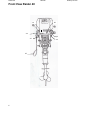
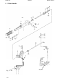
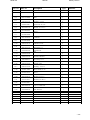
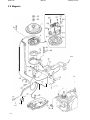
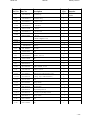
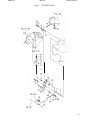
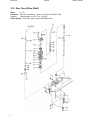
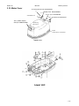
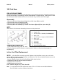
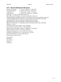
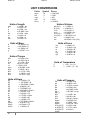
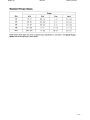
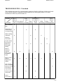
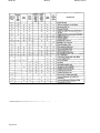
1
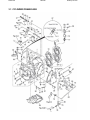
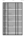
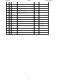
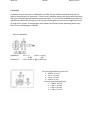
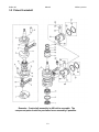
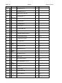
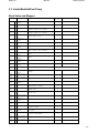
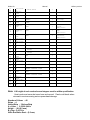
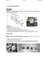
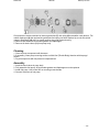
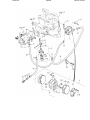
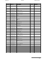
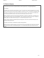
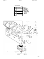
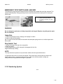
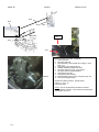
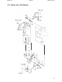
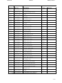
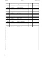
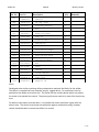
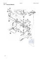
Raider 40 Manual Military version Raider 40 Parts/Assembly Manual Part No. RPAM 40ES-001 RAIDER C-130 Air Dropped Submarine Launched Raider Part No. R40ES-001 Supplement to Raider Service Manual No. R40 ES-001-15-3 Raider No R40ES-001-15-2 January 2015 0 Raider 40 Manual Military version Raider Parts and Assembly Manual R40ES-001-15-2 describes part numbers and illustrates how the Raider subassembly is put together. This manual is a supplement to the Raider Service Manual R40ES-001-15-3 that describes in detail all steps required to repair the Raider 40. Raider Outboard makes no warranty, express or implied, regarding the use of this data. Raider Inc. assumes no responsibility for errors or omissions nor assumes any liability for damages resulting from the use of the information contained herein. I n some cases a part design may have changed since this manual was published or may not apply to your particular engine serial number, or a service/parts bulletin may have been issued containing important information pertaining to this model and/or a particular part. Some parts may be serial number and/or model number specific. You are strongly advised to contact Raider for all up to date information (321) 403-3585. This Raider 40 manual has all parts and assembly data contained herein. It has been presented to help the user identify parts, identify part numbers, how that part has been assembled and tools required to repair the part or secure a new part if required. The Raider is a military only engine and will not be sold to commercial market. It is submersible and runs multiple fuels. An additive must be placed into JP-5/JP-8 to be in compliance with EPA. This manual, Parts/Assembly Manual 40 ES-001-15-2 provides detailed drawings and part numbers for the Raider outboard motor. This is a supplement to the Service Manual No. R40ES-001-15-3 that describes in detail how to remove; repair and the Raider 40. For background purpose’s the Raider 40 comes from a family of motors that have an extensive history of reliability and performance and are identical in parts except for the branding and pricing. These motors are Mercury; Nissan; and Tohatsu. Supporting Raider with common parts available at local dealers supports a low life cycle cost for the Government – with worldwide support. The Mercury, Nissan and Tohatsu outboards are Commercial Off The Shelf (COTS) engines with a long history of performance and reliability. Raider takes the basic COTS and modifies the outboards specifically for the military. We have eliminated as many electrical components as possible and use only the highest reliable mechanical parts. Key components of the Raider features a fuel induction system (FIS) which allows burning of multiple fuels. To go from gasoline to heavy fuels three knobs are turned on the FIS unit. Second key component is the dewatering system. New heads were developed with special valves that allows water to be quickly eliminated between the heads and the pistons. Another key component is a high performance spark plug, made of stainless steel with a robust spark. This spark plug was developed to allow submersion without the need to replace spark plugs after submersion. A secondary start system has been installed that uses a battery to provide quicker starts. The battery is located under the cowling. A grab rail has been installed to easily carry the motor and the second is protection of the Raider outboard when dropped. A new slide plate has been installed in the COTS engine to allow for easier placement on the rubber inflatable boat, especially in higher sea states. Raider 40 Manual Military version Parts and Assembly Manual Section Description Page No. 1 General Precautions, Break in procedures……………. 1. Checklist prior to mission 2. Raider Break-In Procedures 2 2 Raider Engine Overview …………………………………. 4 3 Engine Information ……………………………………….. 3.1 Cylinder/Crankcase ……………………………….. 3.2 Cylinder/Crankshaft ……………………………….. 3.3 Intake Manifold/Fuel Pump ………………………. 3.4 Multi-fuel (Throttle Body) Atomizer …………… 3.5 Fuel Pump/Oil System …………………………. 3.6 Throttle Mechanism ……………………………… 3.7 Tiller Handle ……………………………………….. 3.8 Magneto ………………………………………….. 3.9 Electrical System ……………………………….. 3.10 Dewatering System ………………………………. 3.11 Recoil Starter ……………………………………… 3.12 Starter Lock ………………………………………. 3.13 Drive Shaft Housing ……………………………. 3.14 Gear Case (Drive Shaft) ………………………… 3.15 Gear Case (Propeller Shaft) …………………… 3.16 Shifter ……………………………………………… 3.17 Transom Bracket ………………………………… 3.18 Reverse Lock (Transom Bracket) …………….. 3.19 Raider Motor Covering (Cowl) ………………… 3.20 Fuel Hose …………………………………………. 3.21 Two Raider Motor Configuration …………….. 3.22 Tool Kit …………………………………………… 5 8 9 10 11 13 17 19 21 24 29 31 34 39 41 44 47 51 55 56 57 59 60 4 Engine Details ………………………………………….. 4.1 Tune Up procedures …………………….. 4.2 Lubrication ……………………………….. 4.3 General Service Information ……………. 4.3.1 General Equipment Required ……….. 4.3.2 Consumables Required ……………… 4.3.3 Operational Information …………….. 4.3.4 Unit Conversions ……………………… 4.3.5 Standard Torque Values …………….. 4.3.6 Trouble shooting ……………………….. 61 61 61 62 62 63 63 65 66 68 5 Recommended Spare Parts Kit …………………….. 70 1 Raider 40 Manual Military version Section 1. GENERAL PRECAUTIONS WARNING Gasoline is extremely flammable and can explode if mishandled. 1. Before performing any service work on the fuel system, read and understand Section 1 - Service Safety. 2. Before servicing the fuel system, disable the ignition system by removing all spark plug leads to prevent accidental starting of engine. 3. Fuel leakage can contribute to a fire or explosion. After service work is complete and engine is fully assembled, always run the engine momentarily to pressurize the fuel system. Then check for leaks. 4. Never attempt to run the engine with any fuel system component removed or disconnected. 5. Check fuel hoses and other nonmetallic components for indications of damage or deterioration. Always replace components with authorized factory replacement parts suitable for fuel systems. 6. Clean up fuel spills immediately and store rags in approved containers. Keep drained fuel in approved containers for proper disposal. 7. When using compressed air to clean or dry parts, make sure the air supply is regulated not to exceed 25 psi [172 kPa / 1.76 kg/cm2]. 1.1 Checklist prior to Mission: 1. Fuel/Oil System 50:1 Mix in bladder a. Fuels must be premixed. b. Insure additive is placed in bladder if JP-5 or JP-8 is used (EPA) 2. Electrical System a. Clean spark plugs, replace if necessary, check gap b. Check condition of battery c. Check stop switch operation 3. Control wires and linkage a. Dewatering linkage works smoothly b. Check state of linkages c. Check choke control 4. Recoil starter a. Check wear or damage on starter rope b. Check state of ratchet gear 5. Clutch, propeller a. Check wear or damage on propeller b. Check condition of split pin 6. Other check points a. Condition of trim tab (anode) b. Corrosion or damage 2 Raider 40 Manual Military version 1.2 RAIDER BREAK-in PROCEDURES CAUTION Failure to follow the Break-In Procedure in Owner’s Manual and special fuel mixture requirements for break-in may lead to serious engine damage and shortened engine life. To prevent serious engine damage and ensure long engine life, new engines, used engines with new powerhead, used engines with newly rebuilt powerhead, and engines coming out of storage must be run for a period of 10 hours in accordance with the break-in procedure. First 10 Minutes • Operate the engine at minimum idle speed • Verify a steady stream of water from the cooling water check port and idle port on the engine, indicating the water pump is functioning properly. Next 50 Minutes (0.16 to 1 Hour) DO NOT operate the engine above 1/2 throttle. DO NOT maintain a constant throttle setting. Vary engine speed from 1/4 to 1/2 throttle every 15 minutes. NOTE For boats which come onto plane easily, use full throttle to quickly accelerate onto plane; then immediately reduce throttle to 1/2 and maintain this speed. Next Hour (1 to 2 Hours) • Use full throttle to quickly accelerate boat onto plane; then immediately reduce throttle to 3/4 and maintain this speed. • At intervals, run engine at 3/4 throttle for 1 - 10 minutes; then return to 1/2 throttle for a cooling period. • Vary engine speed every 15 minutes. • Check for water discharge from cooling water check port Next Eight Hours (2 to 10 Hours) • Run engine at 3/4 throttle. • For short periods of time, run engine at full throttle and then reduce speed back to 3/4 throttle. As this part of the break-in period progresses, open to full throttle for longer and longer periods of time, but never longer than 5 minutes. • Vary engine speed every 15 minutes. DO NOT exceed the Full Throttle RPM Range of the engine. See Engine Specifications. After Break-in • Re-torque cylinder head bolts to specification after engine has been run and cylinder head has cooled to the touch. 3 Raider 40 Manual Military version Section 2. RAIDER ENGINE OVERVIEW The Raider Outboard 40 horsepower engine has been designed specifically for the military. It operates on gasoline, Avgas, JP-5, JP-8, kerosene and diesel #2. It is a simple two-stroke; two-cylinder outboard. Special Features: 1. 2. 3. 4. 5. Submersible Multi-fuel capability Special transom mount adapter Wrap around grab bar for easier carrying (engine protection) Fuel additives to assist meeting EPA standards when operating JP-5 and JP-8 fuels Section 3 will describe the Raider 40 outboard in detail. This information includes part numbers, how to assemble/disassemble each part. Section 4 will present engine details including Tune-Up procedures, troubleshooting and special tools required for overhaul and maintenance. Section 5 provides a list of “recommended spare parts” that supports the Raider 40 outboard and is included in each ”spare parts kit”. 4 Raider 40 Manual Military version Section 3. ENGINE INFORMATION 25 1. 2. 3. 4. 5. 6. 7. 8. 9. 10. 11. 12. 13. 14. 15. 16. 17. 18. 19. 20. 21. 22. 23. 24. 25. 5 Cowl tilt handle Motor Cover – Upper Cooling Water Check Port Water Plug Tilt Stopper Drive Shaft Housing Anti-Cavitation Plate Trim tab Propeller Starter Handle Shift Lever Throttle Grip Clamp Screw Handle Stern Bracket Thrust Rod Oil Plug (Lower) Water Strainer Oil Plug – Lower Retainer to transom Stop switch Choke knob Electric Starter button Fuel connection Dewatering lever Wrap around grab rail Raider 40 Manual Military version Front View Raider 40 11 20 24 25 19 6 23 25 Raider 40 Manual Military version Raider 40 Overview 7 Raider 40 3.1 CYLINDER/CRANKCASE Manual Military version Raider 40 Ref.No. Manual Part No. Description Military version Remarks Q’ty M40C 1-1 1-2 1-3 1-4 1-5 1-6 1-7 1-8 1-9 110 111 112 113 114 115 116 117 118 119 120 121 122 123 124 125 126 127 128 129 130 131 1- 361B011002 393-011370 393-011310 345-001170 345-011501 9161290850 9161240840 9161F40835 9401210800 345-011110 R61B010011 R50-01093 345-010051 9161F90845 345-010150 9701-11015 345-010300 RH6B010310 R46-010320 R101F45630 338-602182 9101030616 345B023012 345-023051 9101F45620 98AL-40230 393-011600 3T5-011330 338-011330 336-069730 9101036612 345B05101- CYL BLOCK & CRANKCASE ASSY 1 * NIPPLE 1 * NIPPLE 5.5-5 1 * DOWEL PIN 2 * CHECK VALVE ASSY 1 * BOLT 1 * BOLT 8 * BOLT 1 Bearing 10 * WASHER * DOWEL PIN 6-12 2 CYLINDER HEAD 1 * CYLINDER HEAD PLATE 1 CYLINDER HEAD GASKET 1 BOLT 10 WASHER 8.5-19.5-3.2 10 SPARK PLUG (BR7HS10) 2 NGK THERMOSTAT 1 Mark 52A PRV DEWATERING VALVES 2 DEWATERING FLANGE 1 DEWATERING ROD 1 ANODE 1 BOLT 1 EXHAUST COVER (OUTER) 1 EXHAUST COVER GASKET 1 BOLT 9 HOSE 1 CHECK VALVE 1 CLIPφ8 1 CLIPφ7 1 CLAMP 6-9.5L 1 BOLT 1 BRACKET 1 9 98AL-401000 Raider 40 Manual 32 0 133 134 135 136 137 138 139 140 141 142 143 144 145 146 147 148 149 150 151 152 153 154 155 156 157 158 159 160 161 162 163 164 165 166 9153240825 9401210800 9301210800 9215030520 9301030500 309-069720 345-013031 361-052110 345-052130 345-052231 345-052211 345-052221 9301030500 346-052340 353-837281 9516030800 3AA-837190 9413030600 9301030600 9153240825 9401030800 345-010150 345-637130 9304030800 9101F40620 9401030600 9414031000 346-637210 345-052240 348-637151 3B7-052430 348-637161 345-052231 9301030500 Military version STUD 2 WASHER 2 NUT 2 SCREW 1 NUT 1 CLAMP 6.5-47.5P 1 ENGINE BASEMENT GASKET 1 STARTER LOCK ARM 1 THROTTLE LIMITER ARM 1 ROD SNAP 3.5-2 3 THROTTLE LIMITER ROD 1 STARTER LOCK ROD 1 NUT 2 ROD JOINTφ5 1 PIN 1 SNAP PIN d=8 1 WASHER 8.5-18-1.6 2 SPRING WASHER 1 NUT 1 STUD 1 WASHER 1 WASHER 8.5-19.5-3.2 1 BUSHING 8-14-4 2 NYLON NUT 8-P1.25 1 BOLT 1 WASHER 2 WAVE WASHER d=10 1 BUSHING 6.2-16-5 1 ROD SNAP 5-2.5 1 ROD 5-75L 1 BALL JOINT CONNECTOR 1 THROTTLE ROD 1 ROD SNAP 3.5-2 1 NUT 1 Raider 40 167 168 169 170 171 172 173 174 175 176 177 178 179 180 181 Manual 3B7-637330 348-637111 9101210840 345-637130 334-662330 9304030800 345-052231 348-637151 346-052340 3B7-637330 9301030500 361-837280 3AA-837190 9516030800 9301030600 Military version ROD SNAP 5-2.5 1 ADVANCER ARM 1 BOLT 1 BUSHING 8-14-4 2 WASHER 8.1-16-1.5 1 NYLON NUT 8-P1.25 1 ROD SNAP 3.5-2 1 ROD 5-75L 1 for MF/EF ROD JOINTφ5 1 for MF/EF ROD SNAP 5-2.5 1 for MF/EF NUT 1 for MF/EF PIN 1 for MF/EF WASHER 8.5-18-1.6 1 for MF/EF SNAP PIN d=8 1 for MF/EF NUT 1 for MF/EF 11 Raider 40 Manual Military version Crankshaft Crankshaft is not an item that is addressed in the field. Raider Outboard should be sent back to depot or manufacturer for inspection. Critical concern would be starting the engine with the electric start prior to dispelling water between piston and heads. It is critical that the dewatering valves are opened after submersion and pull start is firmly and slowly pulled at a minimum of eight times prior to using electric starter. Starting engine after submersion without proper dewatering when using Electric start could damage crankshaft. Service Information Dimension 1 Dimension 2 - 2.071 + 0 in [52.6 + 0 mm] -0.002 - 0.05 1.591 ± 0.002 in [40.4 ± 0.05 mm] 4 Connecting Rod Bearing (small end) 1. .0669 in (17 mm) 2. .827 in (21 mm) 3. 1.03 in (27 mm) 4. 0.079 in (2 mm) Connecting Rod Bearing (big end) 1. 0.984 in (25 mm) 2. 1.260 in (32 mm) 3. 0.787 in (20 mm) 4. 0.138 in (3.5 mm) Raider 40 Manual Military version 3.2 Piston/Crankshaft Remarks: Crank shaft assembly is difficult to assemble. The component parts should be purchased as an assembly if possible. 13 Raider 40 Manual Ref.No. Part No. 2-1 2-2 2-3 2-4 2-5 2-6 2-7 2-8 2-9 2-10 2-11 2-12 2-13 2-14 2-15 2-16 2-17 2-18 2-19 2-20 2-21 2-22 2-23 1 2-24 1 2-25 2-26 2-27 1 2-28 1 345-001220 345-001250 361-000691 361-000310 348-000320 348-000330 348-000340 348-000611 345-000401 345-000430 345-000450 345-001140 345-000510 345-000530 9514070306 345-001130 345-001150 9451073000 345-001160 345-001410 345-001140 345-000420 3C187130-0 361-000011 345-000211 334-000241 3C187123-0 361-000110 Description Military version Q’ty Remarks OIL SEAL 25-55-10 1 RETAINER 50-60-1.6 1 CRANKSHAFT SUB-ASSY 1 * CRANKSHAFT A 1 * CRANKSHAFT B 1 * CRANKSHAFT C 1 * CRANKSHAFT D 1 * CRANK PIN 2 * CONNECTING ROD 2 * ROLLER BEARING 25-32-20 2 * BIG END BEARING WASHER 4 * MAIN BEARING 355520 1 * LABYRINTH PACKING 1 * O-RING 2-49.5 1 * SPRING PIN 3-6 1 MAIN BEARING 5206 1 RETAINER 56-66-1.6 1 C-RING d=30 1 SPACER 30.2-40-2.3 1 SHIM 31-42 A MAIN BEARING 355520 1 ROLLER BEARING 17-21-27 2 PISTON REPAIR KIT 2 STD * PISTON 1 STD * PISTON PIN 1 * PISTON PIN CLIP 2 PISTON RING SET 2 STD * PISTON RING 1 STD 1st Center Upper Lower Raider 40 2-29 Manual 1 345-000110 Military version 1 * PISTON RING 15 STD 2nd Raider 40 Manual Military version 3.3 Intake Manifold/Fuel Pump Reed Valve and Stopper Ref.No. 3-1 3-2 3-3 3-4 3-5 3-6 3-7 3-8 3-9 310 311 312 313 314 315 316 317 318 319 320 321 322 323 324 325 326 327 328 329 Part No. 9153210655 345B020100 345-021040 345-021050 345-021001 9215217412 345-021060 9101217620 345-021030 9101F45630 9153210620 9301030600 9413030600 348-637180 9215030616 346-637210 3C8-663080 9414031000 345-020113 345-671911 345-671920 345-671940 9215030408 356-040001 334-040040 9225F26528 334-040050 334-040070 356-040300 Description Q’ty STUD 2 INTAKE MANIFOLD 1 INTAKE MANIFOLD GASKET 1 INTAKE MANIFOLD GASKET 1 REED VALVE ASSY 1 SCREW 8 PLATE 1 BOLT 1 REED VALVE SEAT GASKET 2 BOLT 7 STUD 2 NUT 4 SPRING WASHER 4 THROTTLE CAM Remarks Ref.No. SCREW 1 BUSHING 6.2-16-5 1 WASHER 6-16-1.5 1 WAVE WASHER d=10 1 CARBURETOR GASKET 1 PRIME ROD 1 PRIME ROD 1 PRIME ROD CONNECTER 1 SCREW 1 FUEL PUMP ASSY 1 * PUMP COVER 1 * SCREW 3 * PUMP DIAPHRAGM 1 * DIAPHRAGM GASKET 1 * DIAPHRAGM GASKET SET 1 -10- Raider 40 Manual 330 331 332 333 334 356-040440 9217220306 9302220300 346-049012 9215036640 335 Military version * CHECK VALVE 2 * SCREW 2 * NUT 2 GASKET 1 SCREW 2 98AB-50160 HOSE 1 336 98AB-50270 HOSE 1 337 98AB-50210 HOSE 1 338 339 340 341 342 343 344 345 346 347 348 349 350 351 352 338-022150 346-022300 346-022370 346-022350 346-022340 9301030800 9401030800 348-022310 345-024110 345-024150 9101F40616 345-024160 9215035508 345-024171 345-671951 CLIPφ10 6 FUEL FILTER ASSY 1 * CUP 1 * GASKET 1 * FILTER 1 NUT 1 WASHER 2 PLATE 1 INTAKE PROTECTION COVER 1 INTAKE SILENCER COVER 1 BOLT 2 INTAKE SILENCER PLATE 1 SCREW 2 INTAKE SILENCER LOCK PLATE 1 BUSHING 1 Fuel Pump F/Connector-Fuel Filter 98AB-501000 Fuel Filter-Fuel Pump 98AB-501000 Fuel PumpCarburetor 98AB-501000 Note: Lift height of each reed valve and stopper must be within specification. Used reeds must never be turned over and reused. Reed could break when returned to service causing serious powerhead damage. Number of Valves - 40 Strips - 4 Valves/Strip - 3 Valves/Strip A = Valve – 0.236-0.244 in Height – (6.0-6.2 mm) B = Gap - 0.0079 in -9Valve End/Valve Seat – (0.2 mm) Raider 40 Manual Military version 3.4 Multi-fuel (Throttle Body) Atomizer The Fuel Induction System (FIS) was given a name replacing “carburetor” as it looks like a carburetor, however, has minimal moving parts. The key to the FIS is the slide as it is shaped larger at bottom; smaller at top; as both flat and round surfaces with serrations in two directions. As the fuel reaches the slide, with harmonic frequency the fuel flows to the top of the slide and gets broken down into very small droplets that burn more effectively than carburetors. -11- Raider 40 Manual Ref.No. 4-3 4-4 4-5 4-6 4-7 4-8 4-9 4-10 4-11 4-12 4-13 4-14 4-15 4-16 4-17 4-18 4-19 4-20 4-21 4-22 4-23 4-24 Part No. RL4-32200 RL43221-0 RL4-0322 RL4-0323 RL4-0324 RL4-0325 RL4-0326 RL4-0327 RL4-0328 RL4-0329 RL4-0330 RL4-0331 RL4-0332 RL4-0333 RL4-0334 RL4-0335 RL4-0336 RL4-0337 RL4-0338 RL4-0339 RL4-0340 RL4-0341 RL4-0342 RL4-0343 4-25 RLS-0344 4-26 4=27 4=28 4=29 4=30 4=31 4=32 4=33 4=34 RLS-0345 RL4-0346 RL4-0347 RL4-0348 RL4-0349 RL4-0350 RL4-0351 RLS-0352 RL4-0353 4-1 4-2 Description Military version Quantity MULTI-FUEL ATOMIZER 1 SLIDE 1 PUSH PULL KNOB CHOKE RETAINER BOOT CHOKE ASSY COMPONENT 2709 CHOKE ASSY COMPONENT 2709 CABLE CHOKE ASSY 2719 MFA BODY IDLE KIT COMPONENT VENT LINE 2430 IDLE KIT COMPONENT 2759 VENT CLIP FLOAT DUIDE PIN 2280 INDEPENDENT FLOAT -LEFT 2202-1 INDEPENDENT FLOAT -RIGHT 2202-R FLOAT LEVER 2200-1 FLOAT BOWL SCREW 2320 FLOAT BOWL -POWER JET 2300 PJ DUAL FLOAT ASSY 2200-D FLOAT BOWL GASKET NEEDLE & SEAT GRAVITY 2500-030 NEEDLE & SEAT GASKET 2501 TOP COVER GASKET 2010-G TOP COVER TOP COVER SCREWS 9PKG. 3) 2010-0 BRASS CABLE ADJUSTORS CABLE WEATHER SEAL 2150 POWER JET NOZZLE (LONG) 2810-L POWER JET 2800 PJ CAP SCREW & GASKET 2709 METERING ROD 2600 SLIDE SPRING 2022 FUEL SCREEN FUEL SCREEN ENCAPSULATOR 2335 1 1 1 1 1 1 1 1 1 1 1 1 1 1 1 1 1 1 1 1 1 1 Remarks 1 1 1 1 1 1 1 1 1 1 -12- Raider 40 Manual Military version 3.5 Fuel Pump/Oil System Fuel Pump CAUTION: Before servicing the fuel pump, disconnect the fuel hose from the engine to prevent excessive fuel spillage. Inspection 1. Inspect pump body (1) for cracks. 2. Inspect check valves (2) for deformation. 3. Inspect pump covers (3) for cracks and surface deformation. 4. inspect guide plate (4) and spring (5), if equipped, for deformation and tension. 5. Inspect gasket between crankcase and fuel pump for dryness (crankcase-mounted pumps). Disassembly NOTE: Match mark parts before disassembly and reference the illustrations in the Inspection procedure to ensure proper orientation of internal components. 1. Expand and move clips (1) on fuel hose(s) (2). 2. Disconnect fuel hoses from fuel pump. 3. Loosen pump mounting screws (3) and remove fuel pump (4) and gasket from crankcase. 4. Remove fuel pump cover screws (5) and cover (6). Gently separate the pump components. Raider 40 Manual Military version Past production model contained an internal guide plate (7) and spring (8) assemblies under tension. The rubber diaphragm (9) that required the guide plate and spring has been replaced by a resin film (white opaque) diaphragm (10) which no longer requires the guide plate and spring. 4. Remove and discard all serviceable gaskets and diaphragms. 5. Remove ail check valves (11) from pump body. Cleaning 1. Clean ail pump components with kerosene. 2. lf necessary, clean pump mounting surface on Multi-fuel (Throttle Body) Atomizer with isopropyl alcohol. 3. Dry all components with low pressure compressed air. Assembly 1. Install all check valves in pump body. 2. Fully assemble fuel pump. Ail serviceable gaskets and diaphragms must be replaced. 3. install fuel pump. Use Loctite 242 on mounting screw threads. 4. Connect fuel hoses to fuel pump. -14- Raider 40 Manual I \..... ..... - Military version I I I I -- I -5 I I -- I I I _ _ _ _ _ _ _ _ _ _ _ _ _ .! I I Raider 40 Ref. No. Manual Part No. Description Military version Q’ty 5-1 356-04000-1 5-1-1 334-04004-0 5-1-2 92251 2-6528 5-1-3 334-04005-0 5-1-4 334-04007-0 5-1-5 356-04030-0 5-1-6 356-04044-0 5-1 -7 921 722-0306 5-1-8 930222-0300 * Pump Cover * Screw * Diaphragm . * Gasket "B", Diaphragm * Diaphragm Set * Check Valve * Screw * Nut 5-2 346-04901 -0 Gasket. Fuel Pump 1 5-3 921503-6640 Screw 2 5-4 346-02230-0 Fuel Filter 1 5-4-1 346-02234-0 5-4-2 346-02235-0 5-4-3 Fuel Pump Remarks 1 1 3 1 1 1 2 2 2 346-02237-0 * Filter * Gasket * Cup 1 5-5 9301 13-0800 Nut 1 5-6 9401 13-0800 Washer 2 5-7 348-02231 -0 Plate. Fuel Filter 1 5-8 98AB-5-01 60 Fuel Pipe 1 5-9 98AB-5-0270 Fuel Pipe 1 5-10 98AB-5-0210 Fuel Pipe 1 5-11 338-0221 5-0 Clip #10 6 5-12 336-06973-0 Clamp, 6-9.5L 1 5-13 910113-5612 Bolt 1 5-14 382-70260-1 Fuel Connector (Engine, Male) 1 5-15 332-70261-0 Nut, 10-Pl .25 1 5-16 336-701 12-0 Gasket 10.2-16-0.5 1 1 1 -16- Raider 40 3.6 Throttle Mechanism -17 - Manual Military version Raider 40 Ref. No. 6-1 Manual Military version Part No. Description Q’ty 348-63711-1 Advancer Arm 1 6-2 9101 21 -0840 Bolt 1 6-3 345-63713-0 Bushing:. 8-14-4 2 6-4 930406-0800 Nylon Nut. 8P-1.25 1 6-5 3P0-66233-0 Washer. 8.1-16-1.5 1 6-6 921 506-0520 1 6-7 930106-0500 Screw Nut 6-8 361 -83728-0 1 6-9 930106-0600 Cable Pin Nut 6-10 348-63715-0 Link Rod. 5-75L 2 6-11 3B7-63733-0 Rod Snap. 5-3 2 6-12 346-05234-0 #5 Rod Joint 1 Nut Remarks or 334-66233-0 1 1 6-13 930106-0500 6-14 348-63716-0 Throttle Link Rod 1 6-15 345-05223-1 Rod Snap. 3.5-2 2 6-16 348-63718-0 Throttle Cam 1 6-1 7 346-63721 -0 Bushing:, 6.2-16-5 1 6-18 941403-1000 Wave Washer, d=10 1 6-19 921503-061 6 Screw 1 6-20 3R0-66308-0 Washer, 6-16-1.5 1 6-21 353-83719-0 1 6-22 951603-0800 Washer, 8.5-18-1.6 R-Pin, d=8 6-23 3B7-05243-0 1 6-24 346-05228-0 Cap "C". Ball Joint * Ball Joint "B" 2 1 1 -18- Raider 40 Manual Military version 3.7 Tiller Handle 15 25 6 21 · 3 ..:.::---· Fig. 19-1 -19 - Raider 40 Ref. No. 6-1 Manual Military version Part No. Description Q’ty 348-63711-1 Advancer Arm 1 6-2 9101 21 -0840 Bolt 1 6-3 345-63713-0 Bushing:. 8-14-4 2 6-4 930406-0800 Nylon Nut. 8P-1.25 1 6-5 3P0-66233-0 Washer. 8.1-16-1.5 1 6-6 921 506-0520 1 6-7 930106-0500 Screw Nut 6-8 361 -83728-0 1 6-9 930106-0600 Cable Pin Nut 6-10 348-63715-0 Link Rod. 5-75L 2 6-11 3B7-63733-0 Rod Snap. 5-3 2 6-12 346-05234-0 #5 Rod Joint 1 Nut Remarks or 334-66233-0 1 1 6-13 930106-0500 6-14 348-63716-0 Throttle Link Rod 1 6-15 345-05223-1 Rod Snap. 3.5-2 2 6-16 348-63718-0 Throttle Cam 1 6-1 7 346-63721 -0 Bushing:, 6.2-16-5 1 6-18 941403-1000 Wave Washer, d=10 1 6-19 921503-061 6 Screw 1 6-20 3R0-66308-0 Washer, 6-16-1.5 1 6-21 353-83719-0 1 6-22 951603-0800 Washer, 8.5-18-1.6 R-Pin, d=8 6-23 3B7-05243-0 1 6-24 346-05228-0 Cap "C". Ball Joint * Ball Joint "B" 2 1 1 -20- Raider 40 Manual Military version 3.8 Magneto 12-1 20 I 6 16 -22 I 16-1 -21 - 20 \ 7 . / Raider 40 Ref. No. Manual Part No. Military version Description Q’ty 8-1 361-06091 -0 Flywheel Cup 1 8-2 3A0-06002-0 Coil Plate Ass'y 1 8-2-1 3G2-06022-0 8-2-2 3A0-06023-0 8-2-3 921521 -6528 8-2-4 3G2-06021-0 8-2-5 8-2-6 921521-6522 350-06025-0 8-2-7 8-2-8 921521 -6406 921521-6406 921521 -6408 921521-6408 * Pulser Coil * Alternator * Screw * Exciter Coil * Screw * Holder. Magneto Cord *Screw *Screw FP5506 #91569 1 1 2 1 2 1 3 2 4 8-3 921521 -6510 9215216510 *Screw 8-4 361-06060-1 G.D. Unit 1 8-5 910103-6625 Bolt 5 8-6 3R0-66308-0 Washer, 6-16-1.5 4 8-7 8-8 930113-0600 3A0-06322-1 4 1 8-9 3B7-06305-0 Nut Plate, Electric Rubber Mount. 9-16-4.3 8-10 3F3-06920-0 Rubber Mount, 9-12-2 3 8-11 3A0-76079 -0 Collar. 6.2-9-7.4 3 8-12 361 -06040-1 Ignition Coil (with Resistance Cao) 1 8-12-1 3C7-06921 -0 * Plug 2 8-13 910113-5620 Bolt 2 8-14 941 303-0600 Spring Washer 2 8-15 3B7-76142-0 Ground Cable 1 8-16 398-06830-0 Lanyard Stop Switch 1 8-16-1 353-06821-0 * Lock, Lanyard Stop Switch 1 8-17 345-06917-1 Clamp. 9-20U 1 8-18 9101 14-0820 Bolt 1 8-19 9301 13-0800 Nut Clamp, 6.5-47.5P 1 Cap ( with Resistance) Remarks CU2503 3 L=120 -22- Raider 40 Manual Clamp, 6.5-47.5P Military version 8-20 309-06972-0 8-21 922503-6510 Screw 1 8-22 9101 13-061 2 Bolt 1 8-23 353-76037 -0 Plug:. Cable Terminal 1 8-24 336-76091-0 Band, Lead Wire 1 8-25 931121 -1600 Nut. Magneto (16P-1.5) 1 334-00132-0 Nu t. Magneto (16P-1.5L) 8-26 345-00133-0 Washer. 16-28-3.2 1 8-27 3C7-76142-0 Ground Cable 1 Bolt 1 -23 - 4 (1) #032986XDClockwise #028121XDCounterclockwise L=170 for MF Type Raider 40 Manual Military version 3.9 Electrical System The Raider 40 Electrical system is very straight forward. For the user the secondary starting process is the built in self starter which consists of a protected starter button supported by a small lightweight battery. 3.8.1 Battery. The Raider battery should be removed when not used. To maintain use it must be charged every six months. Prior to mission check to insure the battery voltage is not lower than 12.8 V. This battery is completely sealed and requires no topping of any fluid. Never attempt to open the battery. Short cranking of the Raider 40 is recommended. DO NOT attempt to continuously crank the battery more than 5 times. Battery Installation requires removing cowling; place battery on platform in engine front. The battery has a hole underneath that will match the extended pin. Place in position and install a Velcro strap. Connect the battery cable to the cable inside the motor pan. To remove do the process in reverse. Storage. Battery should be stored with 70 percent charge level. Store in dry cool location away from rain, furnaces of other heat sources. The electric start function is considered a secondary starting method. NEVER use battery to dewater engine as this will cause critical internal damage to the engine when the piston tries to quickly push water out of dewatering valves. This will potentially destroy the internal parts of the engine. -24- Raider 40 Manual Electrical System Overview Ignition type - Flywheel magneto capacitor discharge Spark Plug (with resistor) - SBE1/10 (Pulstar) Spark Plug wires – 2 x 23 015 002 051 (Nology) Spark Plug Gap - 0.040 in [0.9 - 1.0 mm] Battery - Sealed type 12 Volt W/Hr (Wh) – 24 (Ah- 2) Cold Cranking Amps - 140 Engine Fuse - none Rectifier - 04KE03 Starter Solenoid - 2J6 Starter Motor – Part No. 346760100m Starter Switch – #FS-ST05 Moroso 74120 Alternator - 12V 80W Charging Performance (at 5500 RPM) – 5 Amps Number of Tachometer-to-Alternator Coil Impulses - 4 Alternator Coil Resistance - Y-W : 0.65 - 0.98 Ohms Y-B : 0.31 - 0.47 Ohms W-B : 0.37 - 0.55 Ohms lgnition Coil Resistance - (±25%) Primary Coil - 0.2 - 0.3 Ohms Secondary Coil - 4.1 - 6.1 KOhms -25 - Military version Raider 40 Manual Military version Electrical Starter Position Color of lead wires A Yellow B c White Red D Blue/Brown E Green/Black 1-1 Fig. 11-4 _ _ _ .!__ __ _ : : (J) : : !@ i ' '' ' ' : ' '' : '' ' ·-·····:: .. :...:. ' ,. .... 1-2 : Starter Motor ' !1'4 '· . ' . Battery ...-.. I .....,0 !' 1-3 : . 0 ' · ' ' - ....- . . . Fig. 8-5 Bolt Starter Button 9-35 9-36 Starter Button Safety ring -26- Raider 40 Ref. No. Manual Part No. Description Military version Q’ty 9-1 346-76010-0 9-1-1 346-76015-0 9-1 -2 346-76012-0 9-1 -3 346-76013-0 9-1 -4 346-76014-0 * Pinion * Carbon Brush (+) * Carbon Brush (-) * Brush Holder 9-2 916103-0830 Bolt 2 9-3 345-06971-0 Clamp, 9-1 2U 2 9-4 9301 1 3-0800 Nut 2 9-5 941303-0800 Spring Washer 2 9-6 346-76040-0 Starter Solenoid 1 9-7 361-76055-0 Bracket. Choke Solenoid 1 9-8 345-76081-0 Bracket. Neutral Switch 1 9-9 910103-0618 Bolt 2 9-10 9301 13-0600 Nut 2 9-11 941303-0600 Spring: Washer 2 9-12 3G2-76060-0 Rectifier 1 9-13 921503-0525 Screw 1 9-14 930103-0500 Nut 1 9-15 941303-0500 Spring: Washer 1 9-16 353-06281-0 Holder. Cable Terminal 1 9-17 353-06283-0 Collar.6.4-10-4.7 2 9-18 9101 13-0620 Bolt 2 9-19 309-06972-0 Clamp.6.5-47.5P 3 9-20 941303-0600 Spring: Washer 2 9-21 930113-0600 Nut 2 9-22 910103-0645 Bolt 1 9-23 941303-0600 Spring: Washer 1 Starter Motor 1 1 2 1 1 9-24 128-02605-1 Spacer.6-8-28.5 9-25 910903-6616 Bolt 1 2 9-26 352-76062-0 Fuse Wire - eliminated 1 -27 - Remarks or 910103-6645 L=355 Raider 40 Manual Military version EMERGENCY STOP SWITCH AND LANYARD The emergency stop switch and lanyard should be inspected and tested after servicing outboard. The operator should perform Emergency Stop function test with the boat in the water prior to leaving the launch area. 1. Lanyard P/N 361-06305-1 2. Emergency Kit Stop P/N 36106305-2 WARNING Do not attempt to repair worn or faulty stop switch and lanyard. Replace only with genuine parts. Do not substitute. Inspection 1. Inspect lanyard (1) for cuts or fraying, lock clip (2) for cracks. 2. Inspect stop switch assembly (3) For signs of wear and make sure the switch has adequate spring tension to hold the lanyard lock clip in place Stop Switch Test 1. Attach the lanyard lock clip to the stop switch. 2. Start the engine. 3. With engine running, puII the lanyard to disengage the lock clip. Engine should stop running. NOTE The stop switch also operates as a push-button switch with the lanyard left attached. 4. Repeat the test but do not remove the lanyard. Press down firmly and hold the stop switch until engine stops running. If engine continues to run in either test, the stop switch or wiring are faulty and must be replaced before engine is operated. 3.10 Dewatering System 10-2 -28- Raider 40 Manual Military version 10-6 10-1 10-4 10-3 10-6 10-5 10-7 10-5 10-1 10-6 Dewater and Start Procedure: (Pull Start) 1. Connect fuel line. 2. Tilt engine into boat 3. Push dewatering valve toward rear of engine – hold back 10-7 4. Pump primer bulb clearing old fuel 5. Release dewatering against fuel valve 6. Pull slowly 8 times on rope. Even strokes. 7. Tilt engine back to standard position 8. Pump primer two times 9. Pump primer bulb until tight 10. Slide dewatering valve to front of engine (close) 10-1 11. Pull rope until engine starts Dewater and Start Procedure: (Electric Start) Perform 1 – thru – 10 Press start button Caution: Do not hit start button until water is cleared between pistons and head. If this is done internal damage to the engine can occur. -29 - Raider 40 Ref. No. 10-1 10-2 10-3 10-4 10-5 10-6 10-7 10-8 Manual Part No. Description Military version Q’ty DW50540 Dewatering lever 1 DW50541 DW50542 DW50543 DW50544 DW50545 DW50546 DW50547 Head dewatering lever Shoulder Bolt Lock washer Carburetor dewatering valve depressor Dewatering rod Carburetor dewater valve Dewatering valves 1 1 1 1 1 1 2 Remarks 3.10-1 Dewatering System operation The dewatering system is utilized after total motor submersion. After the Raider is installed on the transom and secured the dewatering lever, located on the left side of the motor, is pushed toward the back of the outboard motor. The operator must depress the lever to full back position, then press fuel bulb for four presses. This evacuates all potential water that would be in the carburetor. This action also opens up two dewatering valve located in the head of each cylinder. The operator will slowly pull the starter rope a minimum of eight SLOW pulls. This eliminates all water trapped between pistons and the head. Following instructions located on the motor cowling the Raider should start within five minutes using the pull start. It is critical after submersion the motor is turned over by hand for a minimum of eight slow pulls; insure the rope is engaged prior to pulling as to not put pressure on the pull starter. NEVER use the electric start immediately after submersion as the water trapped will cause internal damage to the outboard. Picture of rear of Raider motor showing head. 10-8 Dewatering Valves P/N DW 50546 “O” Rings on Valves P/N DW50546-A -30- Raider 40 Manual Military version 3.11 Recoil Starter --, I 1-18 I 1-19 11-23 I 1 1-21 I l 1-22 1-24 I 1-9 I 11 I 1-2 I 3 2 -31 - Raider 40 Ref. No. Manual Part No. 1 1-1 345-05000- 1 1 1-1-1 345-05105-1 1 1-1-2 345-05105-1 1 1-1-3 345-05003-1 1 1-1-4 345-051 35-1 1 1 -1-5 345-05122-0 1 1 -1-6 945303-0500 1 1 -1-7 345-05123-0 1 1 -1-8 345-051 24-0 1 1 -1-9 345-05004-0 1 1-1-10 951403-031 6 1 1-1-1 1 345-05132-0 11-1-12 9101 14-0830 11-1-13 941322-0800 11-1-14 940121-0800 11-1-15 930103-0800 11-1-16 941322-0800 11-1-17 336-050 14-0 1 1-1-18 9101 14-0625 1 1-1-19 941303-0600 1 1-1-20 338-0501 9-0 1 1-1-21 345-05013-1 11-1-22 338-05131-0 11-1-23 350-05136-0 11-1-24 345-05134-0 11-1-25 344-051 16-0 11-1-26 345-05225-0 11-2 345-05901-1 Military version Description Q’ty Recoil Starter 1 *Starter Case * Reel * Ratchet * Bushing, Ratchet * Washer. 6.5-23-1.5 * E-Ring, d=5 * Ratchet Guide "A" * Ratchet Guide "B" * Starter Spring * Spine: Pin, 3-16 * Starter Shaft * Bolt * Spring Washer * Washer * Nut * Spring Washer * Guide. Starter Rope * Bolt * Spring: Washer * Starter Handle * Starter Rope * Rope Anchor * 0-Ring:. 2.5-4.5 * Plate. Rope Anchor * Seal Plate. Starter * Shaft. Starter Lock Lever Starter Pulley Remarks 1 1 1 1 1 1 2 1 1 1 1 1 1 2 1 or 910113-0800 1 1 2 2 1 1 5-2000 1 1 1 1 1 1 -30- Raider 40 Ref. No. Manual Part No. Description Military version Q’ty 11-5 91 5314-0825 Stud Bolt 2 11-6 9301 21 -0800 Nut 2 1 1-7 11-8 9401 21-0800 910114-0830 Washer 2 Bolt 1 1 1-9 941 303-0800 Spring: Washer 1 1 1-10 910114-0625 Bolt 2 1 1-11 941 303-0600 Spring: Washer 2 Remarks Recoil Starter Removal 1. Remove the neutral start mechanism components and remove the recoil starter from the engine. 2. Rewind the reel and loosen the recoil starter spring. Note: use a screw driver to put the starter rope in the reel notch. With the rope hooked in the notch, rotate the reel slowly to loosen the rope. Repeat this process until the starter spring does not pull the reel. 3. Remove the handle (7) from the starter rope (8). WARNING: protection) attached to the recoil WARNING: The The Raider Raider 40 40 has has aa neutral neutral start start mechanism mechanism(start-in-gear (start-instarter. This feature disables the engine from starting while in gear (forward/reverse). If the electric gear protection) attached to the recoil starter. This feature disables start is used it will not start the engine unless it is in neutral. the engine from starting while in gear (forward or reverse) During Cleaning andofInspection: reassembly the engine following repair, ensure that you do not All worn, damaged, or missing parts must be replaced. 1. Clean metal parts with solvent and dry with low pressure compressed air. Clean plastic parts with dry cloth. 2. Inspect following components as follows: Starter rewind spring for cracked or broken end loops. • Ratchet and reel stopper springs for deformation or poor tension. • Sliding plates, stopper components, and busing for cracks or signs of wear. • Reel assembly for wear. • Starter housing for sharp or rough edges which could fray starter rope. Starter rope for frays and rope handle for damage. Assembly For assembling, use the procedure reverse to the disassembly: following notes. • When setting the starter spring (2) on the starter spring case (1) direct the outer edge hook of the coil spring to the right and set it in the notch of the starter spring case outer circumference. • When winding the starter spring (2) , rotate the reel (3) to the direction of turn (left turn) at pulling out the rope. Then, set the spring so that the reel rotates 1/4 of a turn to one and 1/4 of a turn when rope is fully pulled out. • Apply anti-freeze grease to both ends of the starter spring (2) and sliding area between the starter shaft bolt (14) and friction plate. • Tighten the starter shaft -33 - bolt to the specified toque. Raider 40 Manual Military version 3.12 Starter Lock (Pull Starter) 12 -34- Raider 40 Ref. No. -35- Manual Part No. Description Military version Q'ty 40 R 12-1 361-05211-0 Lock Arm. Starter 1 12-2 915314-0825 Stud Bolt 1 12-3 345-01015-0 Washer, 8.5-19.5-3.2 1 12-4 345-63713-0 Bushing, 8-14-4 2 12-5 9401 13-0800 Washer 1 12-6 930406-0800 Nylon Nut. 8P-1.25 1 12-7 345-05213-0 Stop Arm . Throttle 1 12-8 346-63721-0 Bushing:. 6.2-1 6-5 1 12-9 9101 14-0620 Bolt 1 12-10 9401 13-0600 Washer 2 12-11 941403-1000 Wave Washer 1 12-12 345-0521 7-1 Rod. Starter Lock 1 12-13 345-05226-0 Lever. Starter Lock 1 12-14 940103-0400 Washer 2 12-15 345-05216-0 Spring, Starter Lock 1 12-16 346-05209-0 Cap. Starter Lock Lever 1 12-17 945303-0600 E-Ring D-6 1 12-18 345-05223-1 Rod Snap. 3.5-2 3 12-19 345-05221-1 Rod. Throttle Stop Arm 1 12-20 353-83728-0 Pin. Rod Joint 1 12-21 930106-0600 Nut 1 12-22 941303-0600 Spring Wash er 1 12-23 345-05224-0 Rod Snap, 5-2.5 1 12-24 345-05222-1 Link , Starter Lock Arm 1 12-25 930106-0500 Nut 1 12-26 346-05234-0 12-27 353-83719-0 Washer, 8.5-18-1.6 1 12-28 951603-0800 R-Pin. d-8 1 12-29 348-05233-0 Plate. Throttle Adjust 1 12-30 921521-6510 Screw 2 5 Rod Joint 1 Remarks Raider 40 Manual Fig.12 Military version STARTER LOCK 12 -36- Raider 40 Ref. No. -37- Manual Part No. Description Military version Q’ty 12-1 361-05211-0 Lock Arm. Starter 1 12-2 915314-0825 Stud Bolt 1 12-3 345-01015-0 Washer, 8.5-19.5-3.2 1 12-4 345-63713-0 Bushing, 8-14-4 2 12-5 9401 13-0800 Washer 1 12-6 930406-0800 Nylon Nut. 8P-1.25 1 12-7 345-05213-0 Stop Arm . Throttle 1 12-8 346-63721-0 Bushing:. 6.2-1 6-5 1 12-9 9101 14-0620 1 12-10 9401 13-0600 Bolt Washer 12-11 941403-1000 Wave Washer 1 12-12 345-0521 7-1 Rod. Starter Lock 1 12-13 345-05226-0 Lever. Starter Lock 1 12-14 940103-0400 Washer 2 12-15 345-05216-0 Spring, Starter Lock 1 12-16 346-05209-0 Cap. Starter Lock Lever 1 12-17 945303-0600 E-Ring D-6 1 12-18 345-05223-1 Rod Snap. 3.5-2 3 12-19 345-05221-1 Rod. Throttle Stop Arm 1 12-20 353-83728-0 1 12-21 930106-0600 Pin. Rod Joint Nut 12-22 941303-0600 Spring Wash er 1 12-23 345-05224-0 Rod Snap, 5-2.5 1 12-24 345-05222-1 Link , Starter Lock Arm 1 12-25 930106-0500 Nut 1 12-26 346-05234-0 12-27 353-83719-0 Washer, 8.5-18-1.6 1 12-28 951603-0800 R-Pin. d-8 1 12-29 348-05233-0 Plate. Throttle Adjust 1 5 Rod Joint 2 1 1 Remarks Raider 40 Manual Military version 12-30 921521-6510 Screw 1 2-31 921 503-0530 Screw 1 1 2-32 930106-0500 Nut 1 2 -38- Raider 40 Manual Military version 3.13 Drive Shaft Housing 10 ;- - -- 9 ' I I I I I I I I I I I I I I I I 17 I I I I I I 16 6 1 -39- , I I I I I I I _ _ _ ...J Raider 40 Ref. No. Manual Part No. Description Military version Q’ty 13-1 345S61030-1 Drive Shaft Housing "L" 1 13-2 345-61 1 11-1 Stud Bolt. Drive Shaft Housing: 1 13-3 9301 13-0800 Nut, Drive Shaft Housing 1 13-4 9161 13-0885 Bolt 8 13-5 3P0-66233-0 Washer, 8.1-16-1.5 8 13-6 9101 13-5620 Bolt 1 13-7 345S611 10-0 Extension Housing: "UL" 1 13-8 9101 13-5840 Bolt 6 13-9 345-61012-0 Gasket. Drive Shaft Housing 1 13-10 345S01301-0 Engine Base 1 13-1 1 345-01303-0 Gasket. Engine Basement 1 13-12 345-01215-0 Oil Seal. 17-30-8 1 13-13 345-671 16-0 13-14 910203-0640 Bolt, Engine Base 2 13-15 941303-0600 Spring: Washer 2 13-16 345-01 1 11-0 Knock. 6-12 4 13-17 345-02314-1 Exhaust Pipe. "s" 1 361-02311-0 Exhaust Pipe. "L" & "UL" 1 13-18 345-02313-0 Lock Plate. Exhaust Pipe 2 13-1 9 9101 13-0625 Bolt 4 13-20 910613-0808 Bolt 1 13-21 332-60006-0 Gasket. 8.1-15-1 1 Remarks 2 -40 - Raider 40 Manual 3.14 Gear Case (Drive Shaft) Ratio: 13 : 25 Lubricant - Genuine manufacturer gear oil or API GL5, SAE #80 - #90 Capacity Approximately 14.2 U.S. fl oz [420 ml] Clutch System - Dog clutch type (Forward-Neutral-Reverse 41- Military version Raider 40 Ref. No. 14-1 Manual Part No. Description 361 S60000-0 345-602 11-0 * Military version Q’ty Gear Case 1 Needle Bearing, 22-30-30 1 14-2 910113-5840 Bolt 6 14-3 332-60005-2 Oil Plug 2 14-4 332-60006-0 Gasket, 8.1-15-1 2 14-5 345-60206-0 Water Strainer 2 14-6 921503-0440 Screw 1 14-7 930406-0400 Nylon Nut. 4P-0.7 1 14-8 345-64302-0 Drive Shaft "L" 1 14-9 345-602 13-0 Bearing. 32304 1 14-10 345-64020-1 Bevel Gear "B" 1 14-11 345-64025-0 Bolt. Bevel Gear "B" 1 14-12 345-64081-0 Shim, 41-51.5-0.1 AR 345-64082-0 Shim. 41-51 .5-0.15 AR 345-64083-0 Shim. 41-51.5-0.3 AR 345-64084-0 Shim. 41-51.5-0.5 AR 14-13 332-65022-0 Key. Pump Impeller 1 14-14 345-65021 -0 Impeller, Water Pump 1 14-15 348-6501 6-1 Pump Case Upper 1 14-16 348-650 1 1-0 Liner. Pump Case 1 14-17 348-65017-1 Pump Case Lower 1 14-18 332-601 11-0 Oil Seal. 17-33-9.5 1 14-19 345-65015-0 0-Ring, 3.2-47 1 14-20 348-65025-0 Guide Plate. Water Pump 1 14-21 348-65029-1 Gasket. Pump Guide Plate 1 14-22 348-65018-0 Gasket. Pump Case Upper 1 14-23 334-6501 2-0 Knock. 4-10 2 14-24 91011 3-5652 Bolt 4 14-25 3B7-65014-0 Seal Rubber Lower, Water Pipe 1 _ Remarks -42 - Raider 40 Ref. No. 43- Manual Part No. Description 14-26 345-65206-0 Seal Rubber Upper, Water Pipe 14-27 345-65205-0 Set Ring, Seal Rubber 14-28 345-65204-0 Lock Rubber , Water Pipe 14-29 345-65110- 1 Water Pipe "L" 14-30 348-66011 -0 Clutch Cam 14-31 348-66013-0 Cam Rod "L" 14-32 951403-031 6 Spring Pin, 3-16 14-33 345-66031- 1 Bushing, Cam Rod 14-34 345-66021 -0 0-Ring, 1.9-6.8 14-35 332-66032-0 0-Ring:. 2.4-1 5.4 14-36 301-66024-1 Stopper, Cam Rod Bushing 14-37 301-66025-0 Gasket. 6.2-11-1 14-38 345-66241-0 Joint Shift Rod 14-39 951403-0312 Spring: Pin, 3-12 Military version Q’ty 1 1 1 1 1 1 2 1 2 1 1 1 1 2 Remarks Raider 40 Manual Military version Section 15. GEAR CASE (PROPELLER SHAFT) Fig. 14- 1 - 19 18 10 16 -44 - Raider 40 Manual Military version Gear Case/Propeller Ref. No. Part No. Description 15-1 15-2 15-3 15-4 15-5 15-6 15-7 15-8 15-9 15-10 15-11 15-12 15-13 15-14 15-15 15-16 15-17 15-18 15-19 15-20 15-21 15-22 15-23 15-24 15-25 15-26 15-27 345-60215-0 348010-1 348-64211-0 348-64215-0 345-64217-0 345-64219-0 345-64221-0 345-64222-0 345-64223-0 345S60101-1 345-60211-0 334-60223-0 9601-0-6007 345-60103-0 348-64030-0 345-64032-0 9101 13-5830 3C8-64231-0 348W64108-0 348-64232-0 345-64124-0 345-64121-0 951503-0325 348-60217-0 353-60219-0 9101 13-5618 353-64036-0 353-64037-0 353-64038-0 Bearing 32007 Bevel Gear “A” Propeller Shaft Clutch Clutch pin Snap, Clutch pin Spring, Clutch Spring Holder, Clutch Push rod, Clutch Housing, Propeller Shaft Needle Bearing 22-30-30 Oil Seal 22-36-10 Ball Bearing 6007 “O” ring 353-69.44 Bevel Gear “C” Washer 22.1-28-3 Bolt Thrust Holder, Propeller Propeller Stopper, Propeller Washer, 17-32-3 Nut, Propeller Split Pin 3-25 Trim Tab Gasket Trim Tab Bolt Shim 36-44-03 Shim 36-44-0.15 Shim 36-44-01 Q’ty 1 1 1 1 1 1 1 1 1 1 1 1 1 1 1 1 2 1 1 1 1 1 1 1 1 1 AR AR AR Remarks Raider Standard Raider Outboards are equipped with seal sacrificial anodes to help protect metal parts from the effects of galvanic corrosion (electrolysis). Disintegration of the anodes indicates they are performing their function. Anodes must be replaced when reduced to 2/3 its original size. Engine corrosion will increase if eroded anodes are not replaced. The powerhead anode provides protection to the powerhead. It is located in the cylinder head. The anode should be replaced whenever work requires removal of the cylinder head or when a complete overhaul of the engine is performed. The following procedure is used to test for proper installation of the anode. Make sure the surface of the anode is clean prior to testing. 1. Calibrate an ohmmeter on the high ohms scale. onnect one meter lead to a ground on the powerhead and the other lead to the anode. The ohmmeter should show a low reading. If not, remove the anode; clean the surface where it was mounted. Install anode and retest. 45- Raider 40 Manual Military version Maintenance Procedure: 1. Drain gear oil completely By removing both upper And lower plugs. 2. Inject oil into lower 3. Replace upper plug, then oil plug hole until it lower plug after withdrawing Flows from upper oil injector. Oil plug. Adjusting Trim Tab If the Rubber Inflatable boat fails to run straight, adjust the trim tab which you will find underneath the anti-cavitation plate. If the boat has a tendency to pull to the right, move the trim tab in direction A as shown in the drawing. If it pulls to the left, move the trim tab towards B. Note: A trim tab is a sacrificial anode that protects against corrosion. Do not paint it as this makes it ineffective. -46 - Raider 40 Manual Military version 3.16 Shifter 1 17 Fig. 14-38 47- 19 Raider 40 Ref. No. Manual Part No. Description Military version Q’ty 16-1 345S66110-2 Shift Lever 1 16-2 345-66137-0 Oil Seal, 10-20-4 1 16-3 345-66121-0 Stopper Plate, shift Lever 1 16-4 910903-6512 Bolt 2 16-5 345-67101-0 Bushing, 10-12.8-42.5 1 16-6 945303-0800 E-Ring:, d=8 1 16-7 332-61315-0 Washer. 10.5-18-1.5 1 16-8 16.9 345-66225-0 930403-1000 16-10 16-11 345-661 15-0 965002-1605 Holder, shift Lever Stopper Steel Ball, 5/16 1 1 16-12 332-661 12-0 Spring, shift Lever Stopper 1 16-13 345-661 19-0 Shim, shift Lever Stopper AR 16-14 9101 14-0618 Bolt 2 16-15 9401 13-0600 Washer 2 16-16 348-66211 -0 Shift Rod 1 16-17 345-66226-0 Grommet. Shift Rod 1 16-18 332-66021 -0 O-Ring:, 2.4-5.8 16-19 951403-0312 1 2 Spring: Pin. 3-12 Shift Rod Lever Nylon Nut , 1O5-1.5 Remarks 1 1 T=0.2 Shifter Developed to be similar to existing military outboards to maintain familiarity for the soldier. The shifter is a mechanical front mounted, easy fit, rugged device. For movement it can be pushed into the Raider to minimize size. The shifter also has a safety device which only allows the motor to be started into neutral. The primary pull starter must be in neutral for the primary start. For electric start caution must be taken. It is possible the motor could start in gear with the electric start. The electric start button has protection against accidental starting, however, caution should be taken to insure the shifter is in neutral. -50- Raider 40 3.17 Transom Bracket -49 - Manual Military version Raider 40 Ref. No. Manual Part No. Description Military version Q'ty 40 R Remarks 17-1 349S62112-0 Stern Bracket (Right) 1 Starboard 17-2 349S62113-0 Stern Bracket (Left) 1 Port 17-3 346-62191 -0 Bracket Bolt 1 17-4 346-62124-0 Nylon Nut. 7/8 1 17-5 349-62126-0 Bushing, Bracket Bolt 2 17-6 346-62127-0 Cap 2 17-7 346-62117-1 Distance Piece 1 17-8 940113-0600 Washer 2 17-9 930113-0600 Nut 2 17-10 940113-0600 Washer 2 17-11 345-621 21 -1 Thrust Rod 1 17-12 345-621 22-2 Spring, Thrust Rod 1 17-13 398S62100-0 Clamp Screw Ass'y 2 17-13-1 398-62103-0 17-13-2 332S62102-1 17-13-3 3C8-62104-1 * Clamp Screw * Handle, Clamp Screw * Rivet. 3-22 17-14 332-62101-0 Pad, Clamp Screw 2 17-15 349S62310-2 Swivel Bracket 1 17-16 348S62010-0 Steering Shaft 1 17-17 345-62417-0 Bushing, 26-32 2 17-18 345-62441-0 Friction Plate. Bracket 1 17-19 346-62421- 1 Spring, Friction Plate 1 17-20 910103-0830 Bolt 1 17-21 3A0-62423-2 Thrust Plate. 27-50-1 1 17-22 346-62424-1 Thrust Plate, 26.5-46- 1 1 17-23 345-62415-0 0-Ring:. 3.5-25.7 1 17-24 348S6141 1-2 Mount Bracket 1 17-25 945103-2500 C-Ring, d=25 1 17-26 344-671 77-0 Grease Nipple 5 17-27 345-61301-0 Rubber Mount (Upper) 2 2 2 2 # 95605- or 9·101 13-0830 -52- Raider 40 Manual Military version 1 -53- Q'ty 40 Ref. No. Part No. 17-28 345-61313-0 Stud Bolt , Rubber Mount (Upper) 2 17-29 345-6131 2-0 Retainer, Rubber Mount 2 17-30 9101 13-5820 Bolt 2 17-31 345-61331-0 Damper Clamp 2 17-32 345-61332-0 Damper Collar 2 17-33 345-61302-0 Rubber Mount (Lower) 2 17-34 345-61321-2 Bolt. Rubber Mount (Lower) 2 1 7-35 345-61333-0 Damper Plate 4 1 7-36 345-61334-0 Lock Plate Lower 2 17-37 348-61309 -0 Shim, 33-40.7-0.5 AR 17-38 945003-4000 C-Ring, d=40 2 17-39 940113- 1000 Washer 2 17-40 930403- 1000 Nylon Nut, lOP-1.5 2 17-41 345-61 322-2 Washer, Rubber Mount (Lower) 2 17-42 930103- 1000 Nut 2 17-43 346-61 323-0 Lock Plate, Rubber Mount 2 17-44 916113-0885 Bolt 2 17-45 940113-0800 Washer 4 17-46 930113-0800 Nut 2 17-47 3C8-62158-0 Ground Cable 1 17-48 910113-5612 Bolt 2 17-49 3A3-62396-0 Ground Cable 2 17-50 910113-5610 Bolt 1 17-51 338-60218-2 Anode 1 17-52 910113-5620 Bolt 1 17-53 348-62141-0 Spring "L", Tilt Assistant 1 for Transom "UL" 17-54 348-62142-0 Spring "R", Tilt Assistant 1 for Transom "UL" Description Remarks R O 20- O 31.7-3mm O 21 - O 40.3-4mm L= 130 L= 110 Raider 40 Manual Military version 17-55 348-62143-0 Shaft. Tilt Assistant 1 17-56 348-62107-0 Raider transom safety support 1 Transom parts should be checked before missions for damage. -54- Raider 40 Manual 3.18 Reverse Lock (Transom Bracket) -55- Military version Raider 40 Manual 3.19 Motor Cover Military version 19-4 Spring Washer P/N: 9413030500M Washer P/N: 9401030500M 9301030500M - Nut Screw – P/N: 9216030516M 19-1 Tilt Handle P/N 345S675210 19-6 Rubber Starter Seal P/N: 3KM675030M Dewatering Instructions 19-8 Rubber Seal P/N: 3F3675010M Upper Unit Lower Unit -56- Raider 40 Ref. No. 56 Manual Part No. Description Military version Q'ty 40 c 19-1 345S67100-2 Motor Cover Lower 1 19-2 345-671 13-0 Rubber Mount. 12-18-2.5 8 19-3 3C7-67114-0 Spacer, 8.4-12-17 4 19-4 9101 13-0835 Bolt 4 19-5 345-671 15-0 Washer, Rubber Mount 4 19-6 338S67141-0 Hook Lever 1 19-7 338-67147-0 Seal Ring:, Hook Lever 1 19-8 350-67105-0 Bushing, 14-16.5-17.7 1 19-9 941403-1400 Wave Washer, d=l 4 1 19-10 345-67142-1 Cover Hook 1 19-11 910103-661 2 Bolt 1 19-12 3R0-66308-0 Washer, 6-16-1.5 1 19-13 3C8-67146-0 Washer, 14-22-1 1 19-14 345-671 61-0 Grommet. 22-3 2 19-15 353-671 62-0 Grommet. Battery Cable 1 19-16 345-83732-0 Grommet. Cable 1 19-17 345-671 17-0 Grommet. 17-2.7 2 19-18 345-671 83-0 Baffle. Air Intake 1 19-19 9101 14-0625 Bolt 2 19-20 9401 13-0600 Washer 2 19-21 361S67500 -4 Motor Cover upper 1 19-21 -1 345S67521 -0 19-21-2 921 603-0516 19-21-3 930103-0500 19-21-4 941303-0500 19-21-5 940103-0500 19-21-6 344-67503-0 19-21-7 361S87801- 1 19-21-8 3F3-67501 -0 19-22 369-61016-0 * Tilt Handle * Screw * Nut * Spring Washer * Washer * Seal Rubber. Starter * Decal Set * Seal Rubber. Motor Cover Upper Grommet. 29-3 1 4 4 4 4 1 1 set 1 1 Remarks # 93201 - # 96958- Raider 40 Manual Military version 3.20 Fuel Hose FUEL HOSE AND PRIMER Separate fuel tanks are connected to the engines by a hose with a primer bulb. The primer bulb forces fuel into the Multi-fuel (Throttle Body) Atomizer float chamber for engine starting. Check valves on each side of the primer bulb maintain fuel flow, in one direction only, from the tank to the engine. Disassembly 1. Remove and discard hose clamps (1) and primer bulb clamps (2) as required. 2. Remove tank connector (3) and hose (4). 3. Remove engine connector (5) and hose (6). 4. Remove primer bulb assembly (7). Remove check valves (8) and (9) from primer bulb (10). NOTE Note direction of fuel flow as indicated by the arrow on the primer bulb. Cleaning and Inspection 1. 2. 3. 4. 5. 6. 7. 8. 9. 10. 11. Clamp P/N Clamps P/N Fuel Connector – Bladder P/N 9999800MA2 Hose – P/N Fuel Connector – Engine P/N 3B2702501M Hose – P/N Primer Bulb – P/N Connector Connector Primer Bulb P/N System P/N 3E070-2001M 1. Clean components using soap and water. 2. Dry all components with low pressure compressed air. Make sure all parts and passages are completely dry. in-Line Fuel Filter Replacement NOTE: In-line fuel filters cannot be serviced. Replace in-line fuel filters once a year or with each tune-up. When replacing an in-line fuel filter, note direction of fuel flow as indicated by the arrow on the filter housing for proper installation. 1. Loosen clips (1) on each side of the filter (2) and slide down the hose. 2. Separate the fuel filter from the hoses and discard. 3. Replace with new fuel filter. 4. Attach hoses and secure clips. Fuel: Gasoline; Avgas; JP-5; JP-8; Diesel #2 Note: To comply with local EPA requirements when JP-5 or JP-8 fuels are used Raider Additive Must be added to reduce smoke and emissions. -58- Raider 40 Manual Military version 3.21 Two Motor Configuration Dual Motor Control and Throttle (DMCT) 18 to 26 inches Raider can be used in a two engine configuration to power the conventional 15 passenger Rubber Inflatable Boat. The motors are placed on the transom where the DMCT connecting rod can be screwed into the bolt located on each side of the Raider. Simply place one on the first engine and move the second engine into position to accept the second screw. After installation of the DMCT both engines can be controlled via a single tiller. Then place the DMCT cable on both engines to provide throttle control of both engines by the throttle on the tiller arm. 56 Raider 40 Manual Military version 3.22 Tool Kit Tools: Tool bag Pliers 10 x 13 mm socket wrench 21 mm socket wrench Socket wrench handle Slotted-head screwdriver Spare Parts: Starter rope Spark Plugs (2) Split Pin (Cotter Key) Other: Plastic emergency clip -60- Raider 40 Manual Military version Section 4. RAIDER ENGINE DETAILS 4.1 TUNE-UP PROCEDURE WARNING Deteriorated or damaged parts identified during engine tune-up must be replaced in order to maintain safe engine operation. 1. Inspect engine for leaks, missing, loose or damaged parts, or other visible defects. 2. Remove each spark plug and check for fouling, cracks in ceramic, and incorrect gap. Replace plugs if needed. 3. Check engine compression. Refer to Cylinder Compression –Test in Section 4. 4. Check ail wiring, connectors, and clamps for damage. Replace parts as needed. 5. Replace fuel filter and inspect Multi-fuel (Throttle Body) Atomizer. Check fuel hoses for deterioration. Replace as needed. 6. Check for proper clutch engagement and make shift linkage adjustments as need 4.2. Lubrication for Raider 40 Lubrication Lubrication Chart Lubrication Points and Lubricant Lube Type 1 2 1 -6156 Frequency/Hrs. Figure 1. Shift Lever Mechanism Throttle Cable Figure 2. Throttle Linkage 50 50 50 Raider 40 Manual Military version 4.2.1 General Equipment Required Water Pressure Gauge 0 - 15 psi [0 - 103 kPa / 0 - 1 kg / cm2] Fuel Pressure Gauge 0 - 15 psi [0 - 103 kPa / 0 - 1 kg / cm2] Torque Wrench 0 - 150 in-lb [0 - 17 N·m / 0- 1.7kg-m] Torque Wrench 0 - 750 ft-lb [0 - 1000 N·m / 0 - 100 kg-m] Dial Gauge - minimum scale 0.0001 in [0.01 mm] Micrometer Set or Dial Caliper - minimum scale 0.0001 in [0.01 mm] Telescoping Gauge, Inside Micrometer Set, or Dial Caliper, minimum scale 0.0001 in [0.01 mm] Variable Load High Rate Discharge Tester, Electronic Specialties® Model 700 or equivalent Analog Multimeter, Electronic Specialties® Model M-530 or equivalent Digital Multimeter, Electronic Specialties® Model KD 3200 or equivalent Digital Pulse Tachometer, 10 - 6000 RPM, Electronic Specialties® Model 321 or equivalent Ammeter, 0 - 100 A Gearcase Pressure Tester, Stevens® S-34 or equivalent Gearcase Vacuum Tester, Stevens ® V-34 or equivalent Engine Compression Gauge, 0 - 300 psi [0 - 2000 kPa / 0 - 20 kg/cm2] Spark Gap Tester, Stevens® S-13C, S-48, or equivalent Flexible Fuel Tubing, 1/4 in I.D. x 5 in [6 mm I.D. x 127 mm] Flexible Fuel Tubing, 3/8 in I.D. x 5 in [9.5 mm I.D. x 127 mm] Industrial Thermometer, minimum 300°F [150°C] Heat-Resistant Container, Pyrex® Bearing Puller Seal Pullers Seal Installers Heat Gun Hydrometer -62- Raider 40 Manual Military version 4.2.2 Consumables Required Thread locker, Loctite® 242 Thread locker, Loctite® 243 Gasket Dressing, Permatex® Hylomar® Aerosol High-Temp Gasket Dressing Gasket Sealant, Permatex® High Tack Gasket Sealant Anaerobic Gasket Maker, Loctite® 518 Silicone Sealant, Permatex® Hi-Temp RTV Silicone Gasket Super Bond Adhesive, Permatex® Super Glue Gel Cleaning Pads, Scotch-Brite® Abrasive Pads Low Temperature Lithium Grease Genuine Grease or Equivalent Friction Surface Marine Grease Power Trim/Tilt Fluid, Nisseki® power torque fluid or GM approved automatic transmission fluid Isopropyl Alcohol Cleaning Solvent Gasket Remover Gear Lubricant, Genuine gear oil or APl grade GL5, SAE #80 - #90 Engine Lubricant, Genuine engine oil or NMMA certified TC-W3 oil Automotive Crankcase Oil, flashpoint above 300°F [150°C] Battery Spray Protector, Permatex® Battery Protector & Sealer Electrical Shrink Tubing, various diameters 4.2.3 Operational Information. Power - Raider 40 HP [29.4 kW] Throttle Setting Full Throttle RPM Range - Raider 40 - 5200 – 5800 - Full Open: Match Mark –BTDC 25 deg. Full Closed (in gear) – ATDC 4 deg. Target RPM – 850 for full closed Fuel Consumption at Full Throttle - 3.49 g/hr Test Propeller - 348-64111-0 Idle RPM In GEAR NEUTRAL Raider 40 850 1000 56 Raider 40 Manual Military version Adjustment Procedure: 1. Rotate the throttle grip to the FAST side until Throttle Stops 2. Adjust ignition timing link so that the timing full open match mark is aligned with the fitting line (Crankcase Mating Surfaces). 3. Adjust the stopper bolt so that the advancer arm touches the full open stopper bolt when throttle is fully opened. 4. Turn the throttle grip toward SLOW side. 5. Adjust the stopper bolt (for full close adjustment) so that it hits the stopper bolt at the position where the magneto coil plate timing mark (fully closed side) meets the ignition timing inspection line (crank case mating surface). NOTE: After making adjustments, check that the advancer arm moves firmly and smoothly. Tighten adjusting nut after completing adjustments. 6. At the neutral and reverse position, the starter lock arm and neutral stop arm controls the engine speed. 7. 8. Adjust the engine ignition timing and Multi-fuel (Throttle Body) Atomizer. See Synchronization and Linkage Adjustments, this section. 9. Remove propeller and inspect propeller shaft oil seal for leakage. Inspect propeller, thrust washer, and other propeller shaft hardware for damage. Replace as needed. 10. Drain and refill the Gearcase with specified gear oil. See Engine Specifications in this section. 11. Lubricate all engine components as specified in the Lubrication Chart, this section. 12. Verify that all bolts and screws are torque to specification by applying a torque wrench to each. 13. Run engine in test tank with proper test propeller and check for the following: • Abnormal engine noise. • Improper clutch operation. • Little or no cooling water discharge from check port and idle port. • Fuel leaks from mating surfaces of crankcase. • Fuel leaks from mounting surface of intake manifold. • Cooling water leaks from mating surfaces of cylinder head. • Cooling water leaks from engine mounting surfaces. • Cooling water leaks from exhaust cover mounting surfaces. • Improper idle RPM and stability. • Defective stop switch. -64- Raider 40 Manual Military version UNIT CONVERSIONS Prefix mega kilo centi milli micro Symbol Power M k c m μ x 1,000,000 x 1,000 x 0.01 x 0.001 x 0.000001 Units of Length mile ft in in km m cm mm x 1.6090 = km x 0.3050 = m x 2.5400 = cm x 25.4000 = mm x 0.6210 = mile x 3.2810 = ft x 0.3940 = in x 0.0394 = in Units of Volume gal (U.S.) qt (U.S.) cu-in cu-in fl oz (U.S.) fl oz (U.S.) cm3 cm3 Units of Mass lb oz kg g x x x x Units of Force 0.45360 = kg 28.35000 = g 2.20500 = lb 0.03527 = oz Lbf lbf N N kgf kgf Units of Torque ft-lb ftin-Ib -lb -m kg-m kg-m N-m N-m N-m x 1.3558 = N-m x 0.1383 = kg-m x 0.1130 = N-m x 0.0115 = kg-m x 7.2330 = ft-lb x 86.8000 = in-lb x 9.8070 = N-m x 0.7376 = ft-lb x 8.8510 = in-lb x 0.1020 = kg-m Units of Power HP HP HP PS PS PS W W W kW kW kW ft-lbf/s ft-Ibf/s ft-lbf/s 56 x x x x x x x x x x x x x x x 1.01400 = PS 745.70000 = W 550.00000 = ft-lbf/s 0.98630 = HP 735.50000 = W 542.50000 = ft-lbf/s 0.00134 = HP 0.00136 = PS 0.73760 = ft-lbf/s 1.34100 = HP 1.36000 = PS 737.56000 = ft-lbf/s 0.00181 = HP 0.00184 = PS 1.35600 = W x 3.78540 = L x 0.94635 = L x 0.01 639 = L x 16.38700 = mL x 0.02957 = L x 29.57000 = mL x 1.00000 = mL x 0.03382 = fl oz (U.S.) x 4.4480 = N x 0.4536 = kgf x 0.2248 = lbf x 0.1020 = kgf x 2.2050 = lbf x 9.8070 = N Units of Temperature °F °C = (1.8 • °C) + 32 = 0.556 • (°F - 32) Units of Pressure Psi psi psi bar bar bar (60°F) kPa kPa kPa kg/cm2 kg/cm2 kg/cm2 in Hg (60°F) in Hg (60°F) in Hg (60°F) kg/cm2 x 0.0689 = bar x 6.8950 = kPa x 0.0703 = kg/cm2 x 14.5030 = psi x 100.0000 = kPa x 29.5300 = in Hg x 0.1450 = psi x 0.0100 = bar x 0.0102 = kg/cm2 x 14.2200 = psi x 0.9807 = bar x 98.0700 = kPa x 0.0333 = bar x 3.3770 = kPa x 0.0344 = Raider 40 Manual Military version -66- Raider 40 Manual Military version Section 4. ENGINE DETAILS SYNCHRONIZATION AND LINKAGE ADJUSTMENTS To ensure consistent engine idling and smooth operation throughout the full RPM range, it is important that each procedure be performed exactly as written and in the following sequence: 1. ignition Timing Adjustment 2. Multi-fuel (Throttle Body) Atomizer Synchronization WARNING Before beginning procedures, disable the ignition system to prevent accidental engine startup. NOTE. The seam at the mating surfaces of the crankcase halves is the alignment point for ail ignition timing degree measurements. TROUBLESHOOTING The troubleshooting chart lists common engine symptoms related to problems with the fuel system. lt also indicates specific malfunctions in the fuel system which may be causing the problem so it can be isolated more effectively. Before beginning major troubleshooting operations on the fuel system, perform the following operations: • Disconnect fuel tank hose from the engine. Connect a known good tank and hose and determine if the problem persists. • Remove and clean the engine fuel filter assembly and replace the filter element. • Replace filter element in the fuel tank pickup tube. -67- 56 Raider 40 Manual Military version TROUBLESHOOTING - Powerhead The troubleshooting chart list common engine symptoms related to problems with the powerhead. It also indicates specific component failures which may be causing the problem so it can be isolated more effectively for the Raider 40. Symptom Check Poor crankcase Seal Ignition timing or Throttle linkage Out of adjustment Water entering Crankcase Hard to start or will not start Low cylinder compression No Runs acceleration rough or fails to or Idles get full erratically poorly RPM o o o o o o Defective Thermostat Fouled, defect. Or incorrect Spark plug; Wrong gap Setting Worn or Defective Cylinder, Piston, rings Or warped Head Blown cylinder Head or Engine base Gasket Worn connecting Rod or crankshaft Bearings, internal Wear limits out Of specification Defective ignition Components Carbon Accumulation in Runs noisy or RPM Engine has decreases overheats vibration o o o o o o o o o o o o o o o o o o o o o o o o o o o -68- Raider 40 Manual Military version Fuel Additive not included Raider 40 Raider 40 Manual Military version Section 5. RECOMMENDED SPARE PARTS KIT The Raider 40 horsepower multi-fuel/submersible outboard engine has been reviewed and all the possible spare parts for sixteen units that can be supported by the users are identified in this section. Where the Raider is used dictates more of some parts than others – like propellers. This list will be updated as required. Engine Spark Plugs Thermostat Thermostat gasket Fuel Pump Electric Starter Push button starter switch Kill switch assembly Fuel Induction Unit -Rebuild Kits FIU -Throttle Cables Recoil manual pull Starter Water pump impellers Props Batteries Sealed Maintainers for batteries (2) Primer Cable Rubber Impellers Emergency tool kit -Spark Plugs (2) -Pliers -Screwdriver -Plug Socket -Pull Starter socket -Pull Rope -Spare emergency stop -Cotter Key -Emergency Kit plastic bag - “L” Socket tool JA-8 Additive Oil Additive 32 3 3 1 3 3 3 1 16 4 1 16 2 4 6 2 16 1 Ground delivered Ground delivered -70- Raider 40 Manual Military version If any discrepancies are found the manual can be updated by called (321) 403-3585 – Raider Outboards. Updates will be automatically done on line. www.raideroutboards.com Manuals will be listed. Password is required for entry. Raider Outboards 707 Main Street Titusville, FL 32796 (321) 403-3585 Other Manuals Available Owner/User Manual R40 ES-001-15-1 Service Manual R40 ES-001-15-3 Raider 40