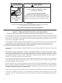
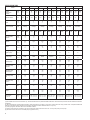
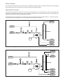
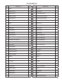
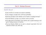
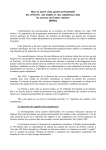
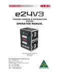
1
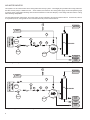
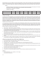
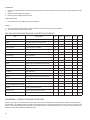
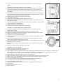
KINNEY® Dry Vacuum Pump Manual 1861-2 0415 ENG WARNING: Do Not Operate Before Reading Manual SDV™ Series OPERATOR’S MANUAL Operator’s Manual: Tuthill SDV™ Series Dry Vacuum Pump Models SDV-120 SDV-200 SDV-320 SDV-430 Tuthill Vacuum & Blower Systems SDV-800 tuthillvacuumblower.com 800.825.6937 WARNING CAUTION DO NOT VALVE OR RESTRICT PUMP DISCHARGE OPENING. USE OIL MIST ELIMINATOR WHEN OPERATING PUMP, ENSURE ADEQUATE VENTILATION WHEN DISCHARGING INDOORS DO NOT OPERATE WITHOUT BELT GUARD REFER TO MANUAL SAFETY INSTRUCTIONS. NOTICE The above safety instruction tags were permanently affixed to your pump prior to shipment. Do not remove, paint over or obscure in any manner. Failure to heed these warnings could result in serious bodily injury to the personnel operating and maintaining this equipment. SAFETY PRECAUTIONS FOR DRY VACUUM PUMPS Please read the following safety information on this page before operating your vacuum pump. • Do not operate the pump without the belt guard properly attached. Disconnect the pump motor from the electrical supply at the main disconnect before removing the belt guard. Replace the belt guard before reconnecting the power supply to the pump motor. Operating the pump without the belt guard properly installed exposes personnel in the vicinity of the pump to risk from rotating drive components. • Do not operate the pump with oxygen-enriched gas (greater than 21% by volume) in the suction line, unless the pump has been prepared with an inert fluid suitable for the application and equipped with seal and start/stop purge system. Pumping oxygen-enriched gases with mineral oil or other non-inert fluids and without proper purges can cause fire or explosion in the pump, resulting in damage or serious bodily injury. • Take precautions to avoid prolonged or excessive exposure to oil mist or process materials emanating from the discharge of the pump. • Do not allow the pump to discharge into a closed, or inadequately ventilated room. Where process vapor contains environmentally unfriendly chemical vapor, pump discharge must be connected to the properly sized scrubber system to neutralize the harmful chemicals prior to the discharge to the atmosphere. Laws and ordinances may pertain to your local area regarding discharge of oil mist, oil vapor, chemical vapor to atmosphere. Check local laws and ordinances prior to operation of the pump with discharge to outside atmosphere. • Do not restrict the pump discharge in any way, or place valves in the discharge line. The vacuum pump is a compressor and will generate high pressures without stalling the motor when operated at low suction pressures. Excessive pressure could cause damage or serious bodily injury. a • Disconnect the pump motor from the electrical supply at the main disconnect before disassembling or servicing the pump. Make sure pump is completely reassembled, the belt guard is properly installed, and that all fill and drain valves are installed and closed before reconnecting the power supply. Accidental starting or operation of the pump while maintenance is in progress could cause damage or serious bodily injury. • Lift pump only by the lifting lugs supplied with the pump. DO NOT lift equipment attached to pump by the pump lifting lugs. • Do not touch hot surfaces on the pump. In normal operation at low pressures, surface temperatures will not normally exceed 180° F (82° C). Prolonged operation at 200 Torr (267 mbar a) may cause surface temperatures as high as 220° F (104° C) 2 TABLE OF CONTENTS SECTION INTRODUCTION PAGE 4 PRINCIPAL OF OPERATION 4 CONSTRUCTION 4 TIMING GEAR 4 BEARINGS 4 OIL LEVEL GAUGE 5 OIL LEVEL SENSOR 5 MATERIALS OF CONSTRUCTION 5 SPECIFICATIONS TABLE 6 PIPING DIAGRAM 7 FRESH WATER-COOLING 7 AIR-WATER RADIATOR 8 PURGES 9 STEAM FLUSHING 10 STEAM FLUSHING METHOD (AFTER PUMP OPERATION) 10 HANDLING PROCEDURE 11 ASSEMBLY OF PIPING 11 PIPING WORK 11 OPERATION 12 PREPARATION FOR OPERATION 12 OPERATION 12 PUMP SHUTDOWN 13 LUBRICATION 13 MAINTENANCE AND INSPECTION 13 GENERAL 13 PERIODIC INSPECTION SCHEDULE 13 DRY VACUUM PUMP MAINTENANCE & INSPECTION SCHEDULE 14 DISASSEMBLY AND REASSEMBLY 15-16 DISASSEMBLY PROCEDURE 15 REASSEMBLY PROCEDURE 16 VACUUM SYSTEM CHECKLIST 19 SPECIAL TOOL LIST 19 EXPLODED VIEW DRAWINGS AND PARTS LISTS WARRANTY – VACUUM PRODUCTS 20-41 42 3 KINNEY® SDV™ SERIES MANUAL 1861-1 © 2008, Tuthill Corporation INTRODUCTION CONGRATULATIONS on your purchase of a new KINNEY® SDV™ Dry Vacuum Pump from Tuthill Vacuum & Blower Systems. Please examine the pump for shipping damage, and if any damage is found, report it immediately to the carrier. If the pump is to be installed at a later date make sure it is stored in a clean, dry location and rotated regularly. Make sure covers are kept on all openings. If pump is stored outdoors be sure to protect it from weather and corrosion. KINNEY SDV vacuum pumps are built to exacting standards and if properly installed and maintained will provide many years of reliable service. We urge you to take time to read and follow every step of these instructions when installing and maintaining your pump. We have tried to make these instructions as straightforward as possible. We realize getting any new piece of equipment up and running in as little time as possible is imperative to production. WARNING: Serious injury can result from operating or repairing this machine without first reading the service manual and taking adequate safety precautions. IMPORTANT: Record the pump model and serial numbers in the OPERATING DATA form on the inside of the back cover of this manual. You will save time and expense by including this reference identification on any replacement part orders, or if you require service or application assistance. This instruction manual describes instructions and precautions to be observed in the handling and maintenance of Tuthill Vacuum & Blower Systems Kinney® SDV Dry Vacuum Pump. It is strongly recommended that those who operate or maintain the pump read this manual carefully prior to pump operation, to ensure longevity of pump life. PRINCIPAL OF OPERATION The SDV Dry Screw Vacuum Pump is a single stage, dry running, non-contact, variable pitch screw type vacuum pump. The design principle of the SDV is simple. Two parallel variable pitch screws, having a highly sophisticated surface profile consisting of an Archimedean and Quimby curve and an arc, rotate in opposite directions. Drive shaft rotation is CW when viewed from the motor end (drive end) of the pump. Helical cut timing gears position these screws relative to each other. The pumped gas is compressed into the discharged port by the rotation of the screws. A specific amount of clearance for each pump size is maintained between the two screws and between screws and housing in order to avoid any metal to metal contact. The power of the motor is transmitted to the main shaft through a coupling or belt pulley. Because the SDV has a variable pitch screw design, the compression process is more efficient and the pump runs cooler. For simplicity and space saving, the models SDV-120 through SDV-800 are provided as standard with flanged adaptors for mounting a C-flange motor directly to the Vacuum Pump, eliminating the need for a separate base frame mounted assembly and coupling guard for the vacuum pumps. The power of the motor is transmitted to the drive screw shaft through a V-Pulley or a coupling, and further to the driven Screw shaft through the timing gears. CONSTRUCTION TIMING GEAR The timing gear is an important part of the screw vacuum pump. The tooth surface is heat cured, and polished with a special high precision tooth-polishing machine for reduced noise during the pump operation. BEARINGS The bearings on the fixed side of the SDV pump (discharge end) are angular contact ball bearings and on the expansion side (inlet end) are roller bearings of heavy load capacity. These bearings have been selected to withstand high speed and heavy load service and to assure the accurate clearances between gears and between screws. 4 OIL LEVEL GAUGE An oil level gauge (sight glass type) is located on the front end cover. Oil should be filled to the top level of the Red Mark, or OL Mark. Oil Levels are indicated as below for the pumps manufactured after October 2005: OL: Original Line (Oil should be filled up to this line initially) RH: Running High (During the Operation) ---- In this case, pump should be checked. RL: Running Low (During the Operation) ---- In this case, pump should be checked. WARNING: If the oil level is too low, gears, bearings and mechanical seals will be damaged as a result of improper lubrication. If the pump were operated with low oil level, the gears and bearings would seize by lack of lubrications. If the oil is overfilled, the oil temperature would get elevated and cause high gear noise and may affect integrities of the other parts within the DE (Drive End) Casing. When pump is not in use, be sure to check the oil level and oil contamination, and then refill or change the oil when needed. The oil is splashed by rotation of the timing gears and lubricates the Bearings and Mechanical Seals. OIL LEVEL SENSOR An oil level sensor is an optional item and may be installed inside the front end cover to sense low oil level and protect the mechanical seals and bearings. In case of improper or low oil lubrication, the oil level switch will send a signal or alarm to alert an operator to refill the oil to the proper level. MATERIALS OF CONSTRUCTION Housing: Ductile Iron (A536 Grade 60-40-18) Various optional corrosion protection coatings (PTFE,NiFlon & NIFA) are available when requested. Screw: Various optional corrosion protection coatings (PTFE,NiFlon & NIFA) are available when requested. Cast Iron (A48 Class No. 30) Shaft: Cr-Mo Alloy Steel (AISI-SAE 4140) Lip Seals: PTFE and Carbon mix (Turcon) in Stainless Steel body Slip Sleeve: Mechanical Seals: Ceramic coated Stainless Steel sleeve with an O-ring for serial numbers up to: SDV-120: S/N 405 SDV-200: S/N 262 SDV-320: S/N 403 SDV-430: S/N 351 SDV-800: S/N 240 Polished Stainless Steel Sleeves (heat fitted) for serial numbers from: SDV-120: S/N 406 SDV-200: S/N 263 SDV-320: S/N 404 SDV-430: S/N 352 SDV-800: S/N 241 Rotor - Stainless Steel Body with Carbon #5 face Stator - Stainless Steel with Tungsten Carbide coating 5 SPECIFICATIONS TABLE MODEL SDV-120 SDV-200 SDV-320 SDV-430 SDV-800 SDV-1500 SDV-2700 50 Hz 60 Hz 50 Hz 60 Hz 50 Hz 60 Hz 50 Hz 60 Hz 50 Hz 60 Hz 50 Hz 60 Hz 50 Hz 60 Hz Nominal Displacement Capacity CFM m³/hr 59 100 71 120 88 150 106 180 157 267 188 320 211 358 253 430 368 625 441 750 765 1300 882 1500 1324 2250 1588 2700 Ultimate Pressure Torr 0.04 0.02 0.04 0.02 0.03 0.01 0.03 0.01 0.03 0.01 0.2 0.1 0.2 0.1 Motor HP kW 5 3 5 3.7 10 7.5 15 11 20 15 50 37 75 55 Power Connection Type C-Flange C-Flange C-Flange C-Flange C-Flange Bare Shaft Bare Shaft Speed RPM Port Size (inches) 150 # FF Inlet Outlet 1.5 1.5 1.5 1.5 2 1.5 2.5 2 4 2.5 5 3 6 4 Gear Oil Gallon(1) Liter 0.13 0.5 0.26 1 0.48 1.8 0.48 1.8 0.58 2.2 1.85 7 2.38 9 Grease Ounces Grams 1 30 1 30 3.5 100 3.5 100 3.9 110 6 170 8.8 250 GPM L/min 0.5 2 1 4 2.1 8 2.9 11 5.3 20 7.4 28 9.5 36 SCFM(3) Sm³/hr NONE NONE NONE 40 (10.6) 29.4 50 94.1 160 100 170 Discharge Temp °F °C <230 110 <248 120 <311 155 <347 175 <455 235 <482 250 <500 260 Max Design Temp Inlet Gas °F °C 122 50 122 50 122 50 122 50 122 50 122 50 122 50 Max Design Temp Discharge Gas °F °C 392 200 392 200 482 250 482 250 572 300 572 300 572 300 Max Design Temp Oil °F °C 158 70 158 70 158 70 158 70 158 70 158 70 158 70 Max Design Temp Grease °F °C 176 80 176 80 176 80 176 80 176 80 176 80 176 80 Noise dBA(4) 72 72 80 80 85 85 90 Weight lbs kg 396 180 484 220 616 280 770 350 1212 550 2310 1050 2970 1350 Inches mm 19 × 13.1 × 10.3 483 × 332 × 262 29.9 × 14.9 × 11.6 760 × 378 × 294 33.8 × 17.1 × 12.8 858 × 434 × 326 39.1 × 19.4 × 13.9 993 × 492 × 352 44.5 × 20.4 × 15.3 1131 × 519 × 389 53.9 × 27.4 × 21.2 1368 × 695 × 539 60.6 × 33.1 × 23 1539 × 842 × 585 Cooling water @ 20o C (68oF)(2) Cooling Purge Dimmensions, L x W x H(5) 2900 3500 2900 3500 2900 3500 2900 3500 2900 3500 1450 1750 1450 1750 (1) Above listed amount of oil is for reference only. Oil should be filled to the top level of Red Mark or NL Mark. Please note that special inert oils are available for hazardous applications. (2) Above listed amount of Cooling Water is based on water temperature of 20°C (68°F). The amount of water varies when using an After Cooler. Temperature differential between Cooling Water supply temperature and discharge temperature shall be maintained below 7°C (12.6°F). (3) Cooling Purge flow rate shown above are at standard conditions. (4) Noise level shown above are based on the pump equipped with exhaust silencer and are from 1 meter (3 feet) away from the pump. (5) dimensions shown above are for bareshaft pump only (without motor). 6 PIPING DIAGRAM The vacuum pump casing and the front end plate have an integrated cooling water jacket. The SDV series pumps can be configured with two different types of cooling systems, Fresh Water Cooling and Circulating Cooling. FRESH WATER-COOLING The fresh water cooling system consists of a “once through” cooling water circuit. A flow indicator, flow switch on the cooling water supply line and temperature guage (or switch) at the cooling water discharge line should be installed to monitor the adequacy of the colling water flow and the cooling water discharge temperature. For SDV-200 and larger-sized pumps, the cooling water circuit is extended to the process exhaust silencer. For SDV-120, silencer is not jacketed, hence, cooling water circuit is not extended to the process exhaust silencer. PROCESS DISCHARGE VG PROCESS INLET PI FSL S COOLING WATER SUPPLY TI SILENCER FI MOTOR SILENCER DRAIN COOLING WATER DISCHARGE COOLING WATER DRAIN Figure 1. Typical Process and Inlet Discharge for SDV-120 with Once-Through Cooling PROCESS DISCHARGE VG TI COOLING WATER DISCHARGE PROCESS INLET PI FSL S COOLING WATER SUPPLY Tl SILENCER FI MOTOR COOLING WATER DRAIN SILENCER DRAIN COOLING WATER DRAIN Figure 2. Typical Process and Inlet Discharge for all other SDV models with Once-Through Cooling 7 AIR-WATER RADIATOR This system is an air-cooled version with a cooling water total recovery system. A centrifugal pump circulates the cooling water from the SDV vacuum pump to a radiator-fan unit. A flow indicator, flow switch on the cooling water supply line and temperature guage (or switch) at the cooling water discharge line should be installed to monitor the adequacy of the colling water flow and the cooling water discharge temperature. For SDV-200 and larger-sized pumps, the cooling water circuit is extended to the process exhaust silencer. For SDV-120, silencer is not jacketed, hence, cooling water circuit is not extended to the process exhaust silencer. VG PROCESS DISCHARGE PROCESS INLET TI PI MOTOR FSL S TI SILENCER FI MOTOR MOTOR SILENCER DRAIN COOLING WATER DRAIN Figure 3. Typical Process and Inlet Discharge for SDV-120 with fan-cooled, re-circulated cooling water system VG PROCESS DISCHARGE PROCESS INLET TI PI MOTOR FSL S TI SILENCER FI MOTOR MOTOR COOLING WATER DRAIN SILENCER DRAIN COOLING WATER DRAIN Figure 4. Typical Process and Inlet Discharge for all other SDV models with fan-cooled, re-circulated cooling water system 8 PURGES COOLING PURGE — Cooling Purge is to cool the inside of the casing and the screws. During the operation of the pump, the process gas introduced into the casing through the suction nozzle is compressed by the rotation of the screws and transferred to the discharge side. Temperature of the process gas gets increased by the heat of compression and this heat energy should be removed in order to prevent the pump from seizure. This Cooling Purge is required for SDV-800, SDV-1500, and SDV-2700. It is optional for the smaller models, SDV-120, SDV-200, SDV-320 and SDV-430. Normally this purge is done by atmospheric air. Where the process gas is not compatible with the atmospheric air, a different cooling medium should be used, such as, Nitrogen, CDA (Clean Dry AIr) etc. For a standard pump, an air filter is provided near the discharge side of the casing. NOTES: • Cooling Purge is not required for SDV-120, SDV-200 & SDV-320 for typical processes. • Flow rates shown below should be applied when the end-user decides to supply Cooling Purge to the pump. • Purge Pressure: Atmospheric pressure for process inlet pressure (operating pressure) 150 torr or below 0.5 kg/cm2g (7.11 psig) minimum for process inlet pressure (operating pressure) 150 torr or higher. • Flow Rates: slpm (sgpm) Cooling purge flow rate can vary depending on the process inlet pressure (operating pressure) Cooling Purge SDV-120 SDV-200 SDV-320 SDV-430 SDV-800 SDV-1500 SDV-2700 30 (7.9) 36 (9.5) 40 (10.6) 40 (10.6) 50 (13.2) 160 (42.3) 170 (43.9) SEAL PURGE — Depending on the application, SDV pump may require Seal Purges. If Seal Purge is specified on your system, it is intended to provide a pressurized barrier within the Front End Plate (FEP) and/or Rear End Plate (REP) with gas which should be compatible with the process gas and the lubrication oil/grease or inert gas such as Nitrogen or Argon, so that the contamination of the lubrication oil and/or the grease within the Front End Cover (FEC) and/or the Rear End Plate (REP) is prevented. Drive End (DE) Seal Purge should be connected to two purge connection nozzles on the Front End Cover. Non Drive End (NDE) Seal Purge should be connected to two purge connection nozzles on the Rear End Plate (REP). (For SDV-120, there’s only one Non Drive End (NDE) Seal Purge connection nozzle.) Both Drive End (DE) and Non Drive End (NDE) Seal Purges can be manifolded from a single source of purge gas supply. Seal Purge pressure should be below 0.5 kg/cm2g (7.11 psig). Leak rate of the mechanical seals is below 3 cc/hr (5.3 x 10⁻⁶ CFM) and they can sustain pressure up to 3 kg/cm2g (42.7 psig). Please note that TVBS does not recommend NDE (Non Drive End) Seal Purge unless it is absolutely required. Providing NDE (Non Drive End) Seal Purge slightly increases the inlet pressure due to the additional mass flow into the pump. Please consult factory for further assistance if you require seal purges. NOTES: • Start/Stop (Cleaning) Purges should last for 20 to 30 minutes with the process isolation valve closed, prior to the start of the process operation and immediately after the completion of the process operation. • Seal Purge Pressure: 0.5 kg/cm2g (7.11 psig) Maximum • Flow Rates: slpm (sgpm) SDV-120 SDV-200 SDV-320 SDV-430 SDV-800 SDV-1500 SDV-2700 DE (Drive End) Seal Purge 3.3 (0.9) 3.3 (0.9) 5.8 - 6.7 (1.5 - 1.8) 5.8 - 6.7 (1.5 - 1.8) 8.3 (2.2) 11.7 (3.1) 11.7 (3.1) NDE (Non Drive End) Seal Purge 0.5 (0.13) 0.8 (0.21) 1.6 (0.42) 2.0 (0.53) 3.7 (0.98) 7.5 (1.98) 13 (3.43) START/STOP (CLEANING) PURGES — Start/Stop (Cleaning) Purge is to remove residual process gas or any incompatible substances such as moisture, atmospheric air etc. from the inside of the pump prior to or after the pump operations. Start/Stop (Cleaning) Purge should be done with gas which is compatible with the process gas or inert gas such as Nitrogen or Argon. This Start/Stop (Cleaning) Purge is especially important when pumping corrosive gases, toxic gases or polymeric process materials such as film resin etc. Start (Cleaning) Purge: With the inlet process isolation valve of the pump closed, operate the pump with purge gas to the pump for 20 to 30 minutes to remove any undesired residual gases from the pump’s internal. The inlet process isolation valve should be open to start process pumping operation upon completion of the Start (Cleaning) Purge. 9 Stop (Cleaning) Purge: Upon completion of process pumping operation, close the inlet process isolation valve and start supplying the purge gas to the pump while the pump is continuously operating for 20 to 30 mintes to remove residual process gas from the pump internals. Motor should be stopped upon completion of the Stop (Cleaning) Purge while the process isolation valve remain closed. NOTES: • Start/Stop (Cleaning) Purges should last for 20 to 30 minutes with the process isolation valve closed, prior to the start of the process operation and immediately after the completion of the process operation. • Purge Pressure: 1.5 kg/cm2g (21.3 psig) Max. • Flow Rates: slpm (sgpm) Start/Stop (Cleaning) Purge SDV-120 SDV-200 SDV-320 SDV-430 SDV-800 SDV-1500 SDV-2700 25 (6.6) 25 (6.6) 40 (10.6) 48 (12.7) 65 (17.2) 160 (42.3) 220 (58.1) STEAM FLUSHING The SDV pump should be operated for 10 to 20 minutes upon completion of process batch cycle with the process isolation valve closed where there’s no Start/Stop (Cleaning) Purge system and sequence in place. This duration of dry operation without process load is to remove any residual process gas or condensed process vapors from the inside of the pump that may have accumulated during the process operation. These residual process materials could be a source of pump motor overload when the pump is restarted. If this residual process material has not been removed by the dry operation after the process operation and the pump is re-started the residual process material inside of the pump could cause a pump seizure by excessive frictional load to the motor or damage the screws and/or the casing. In such case there’s enough amount of the residual process material build-up within the pump, the pump internal should be cleaned out. Steam Flushing is one way to clean the residual process material build-up from the pump internal. When there is enough residual process material build-up, please ensure that the pump is not forced to rotate by the motor. Especially for the processes that have a high potential for build-up and are aggressive in nature, such as, processes with Oligomer, Monomer, Polymer, Resin, etc; should be cleaned out regularly by Steam Flushing. 1. Steam pressure: Approximately 1 kg/cm2g (14.22 psig) 2. System Isolation: Disconnect all electrical and control powers and place lockout tags on the MCC and/or Control Panel to ensure no one accidentally starts the pump during the Steam Flushing. The process isolation valve should be closed. Discharge valve (if applicable) and silencer drain valve should be open. 3. Inject steam for 10 to 20 minutes through the pump’s process inlet (suction) nozzle or one of the nozzles located at the side of the pump’s process inlet (suction) nozzle. Injection time can be varied based on the types and amount of residual process material built-up within the pump. 4. Rotate the pump shaft by HAND to check whether the pump rotates without too much frictions or not. 5. If the pump rotates smoothly by hand rotation, stop the steam injection and start the pump motor with process isolation valve closed. 6. If the pump does not rotate smoothly by hand rotation, repeat steps 3 and 4 until the pump rotates smoothly by hand. Depending on the severity of the residual process material build-up, it may require repeating steps 3 and 4 several times. STEAM FLUSHING METHOD (AFTER PUMP OPERATION) 1. Process materials that require Steam flushing: Oligomer, Monomer, Polymer, Resin, etc. 2. Steam pressure: approx. 1 Kg/cm2g (14.22 psig) 3. Flushing Procedure: Close Suction valve, Open discharge valve or Silencer/Separator’s Drain valve 4. Inject Steam for 10 to 20 minutes (the injection time varies with the process material being removed) through pump suction line or through a plug in suction flange 5. Try to rotate the pump shaft (Pulley or Coupling) by hand to see whether the pump rotates smoothly (during this time, be careful not to start the motor and observe all lock out/tag out procedures). 6. If the pump rotates smoothly, stop injecting steam. 7. Then, start the motor and check if the pump runs normally. 8. If pump does not turn after performing this procedure, it may be necessary to repeat this procedure 2 to 3 times. NOTES: • PURGE PRESSURE: 0.5 to 1.5 kg/cm2 (7.1 to 21.3 psig) • Flow rates listed are Minimum. 10 • FLUSHING PURGE should last for 30 minutes with the pump suction valve closed, after process operation is ended. • All PURGE work except for flushing should be done at the same time as the process starts up. • Sealing purge at NON-DRIVE END can vary a little according to the type of process and operating condition. • The COOLING PURGE amount can vary with the vacuum level. HANDLING PROCEDURE ASSEMBLY OF PIPING LOCATION 1. The pump should be mounted on a base frame with sufficient rigidity and placed on a flat and level surface. 2. If it is to be installed outdoors, please ensure the motor, painting, peripheral equipment, and parts, etc. are suitable for the outdoor operations. 3. There should be enough space around the pump to allow for safe maintenance work and periodic inspections. FOUNDATION 1. Foundation for the pump assembly and it’s base frame should be flat, leveled, and have adequate load bearing capacity. 2. Pump and its base frame, peripheral equipment and piping should be installed when the fountation concrete has been cured. INSTALLATION 1. SDV pumps should always be operated in a horizontal and level position. SDV pumps should never be installed in an upright (vertical) or angled position, and should be installed on a rigid base frame. 2. Pump assembly with the base frame should be placed on a foundation and should be supported evenly. Metal shims should be inserted between the base frame and the foundation, if required for leveling. Pump assembly with the base frame should be leveled to within 0.5 mm (0.02”) in any 1 meter (3.28 ft) 3. Use adequately sized anchorbolts. 4. Upon completion of the setting of the pump assembly on the foundation and anchorbolts, the base frame should be adequately grouted prior to tightening the anchorbolt nuts. Anchorbolt nuts should be tigtened after the grout is firmly cured. Anchorbolts should be tightened evenly to ensure the previously set level is not changed. PIPING WORK MAIN PIPING 1. Process Piping internals should be clean and free from rust, dust, foreign materials, weld slag’s etc. 2. A 40-mesh strainer supplied along with the SDV pump should be placed at the pump process inlet nozzle. After initial start-up and continued operation of the SDV pump for several hours, disassemble the process inlet piping from the pump and check the strainer for cleanliness. If there are any particulates strained such as weld slags etc, clean the mesh strainer and replace to the pump process inlet nozzle. It is highly recommended to check this strainer regularly for its integrity and cleanness. 3. It is required to install expansion joints on the suction side of the pump as well as the discharge side of the pump. These expansion joints are to prevent direct application of any excessive load (primary and secondary load) to the pump assembly from the process piping structures. Process piping must be supported and guided such that the pump assembly is relatively free from any excessive load imposed from the process piping structures. 4. Where process exhaust silencer is provided, it should be installed on or as near to the pump discharge nozzle as possible. 5. A check valve should be installed as close to the process inlet nozzle as possible, which is used to isolate the pump from the process during the pump shut down. The pump will turn in reverse direction if check valve is not present at the process inlet nozzle by the pressure differentials. Where a check valve installation is not permitted for any reason, a process isolation valve, such as a gate valve, should be installed. However, operational procedures must include a pump shut down procedure that includes closure of this process isolation valve prior to pump shut down. It is highly recommended to install a process inlet isolation valve whether a process inlet check valve is installed or not. 6. Where the process gas contains high condensable vapors, a condensate recovery tank should be installed. The tank should be designed to collect the condensates and disposed or drained, as it required. COOLING WATER PIPING — SDV pumps are equipped with an integrated cooling liquid jackets. A cooling medium, typically water, must be supplied to the cooling liquid supply nozzle located at the FEC (Front End Plate) which will be circulated to the pump Casing and discharged from the discharge nozzle located on the Casing. Where water-jacketed discharge silencer or after cooler is supplied with the pump, the silencer or after cooler should also receive the cooling liquid as well. A single loop cooling liquid supply line can by employed by installing piping between the cooling liquid discharge nozzle at the pump Casing to the cooling liquid supply connection 11 nozzle on the silencer or the after cooler. Cooling medium supply piping should include the instruments listed below: * If a Water Jacket type Silencer or After Cooler is installed, this Silencer / After Cooler also requires Cooling water piping. COOLING LIQUID SUPPLY LINE • Manual isolation valve • Strainer • Pressure gauge with an isolation valve • Liquid flow meter • Liquid flow switch (Or, combined cooling liquid flow meter/switch) • On/Off solenoid valve • Flow regulating valve • Temperature gauge COOLING LIQUID DISCHARGE LINE • Temperature gauge • Temperature switch (Optional) OPERATION PREPARATION FOR OPERATION 1. Ensure the pump internal and process piping are thoroughly cleaned and free from weld slags, metal chips, particulates, rusts, dusts etc. 2. Ensure all the process piping connections and utility piping connections are properly installed/tightened and supported. 3. Ensure the lubrication oil at the DE oil reservoir of the pump is filled up to the top level of RED Mark or OL Mark while the pump is NOT in operation. 4. Adjust and set the cooling liquid flow rate listed on the “SDV Technical Data” table. 5. Ensure the electrical power connection to the motor or electrical/control panel is completed and is ready to supply power to the motor. NOTE: Remember that the right oil level is crucial for the pump performance. If the pump were operated with low oil level, the gears and bearings would seize by lack of lubrications. If the oil is overfilled, the oil temperature gets elevated and would cause high gear noise and may affect integrity of the other parts within the DE (Drive End) Casing. OPERATION 1. Ensure the direction of the pump rotation is correct; CW (Clockwise) direction, looking from the motor. A pump rotational direction check can be done by jogging the pump a brief moment while checking the rotational direction of the motor fan. If the motor rotates CCW (Counter-Clockwise), correct the power cable connections and check the rotational direction again to ensure the pump rotates in correct CW direction. Pump rotational direction check should be done with the process inlet isolation valve open. 2. With the process inlet isolation valve open, operate the pump for 20 to 30 minutes. At this stage, all pump operating parameters should be checked for any abnormality; such as excessive vibration, high oil/grease temperatures, high cooling liquid discharge temperature, high process discharge temperature noise, over current draw etc. In case of observation of any abnormality, stop the pump and investigate for the cause of the abnormality. Typical causes of abnormalities come from improper lubrication and/ or improper installation of the pump. 3. Upon completion of the above step, operate the pump for 2 to 3 hours under normal process load condition and check the pump operating parameters again. 4. If an abnormality is found during the initial operation with normal process load, shutdown the pump immediately and ensure the problem is corrected prior to re-startup of the pump. 5. Pump operating conditions should be within the limits shown on the “Specifications Table” on page 6: • Max. Process Inlet Temperature • Process Discharge Temperature • Oil Temperature • Grease Temperature 6. Cooling Medium Differential Temperature is determined by subtracting the Supply temperature from the Discharge temperature. For water, differential temperature must be within 12.6°F. 7. Observe other operating conditions as well, such as: noise, vibration, and motor current draws (amps) PUMP SHUTDOWN 1. Prior to disconnection of the motor power, ensure to close the process inlet isolation valve. 12 2. Where the process gas or vapor is in corrosive or hazardous nature, introduce inert gas, such as Nitrogen or Argon, into the pump inlet for 20 to 30 minutes to purge out the residual process gas or vapor from the pump internals prior to disconnecting the motor power. Please see Start/Stop (Clean) Purge section for more information. 3. Shutdown the pump. 4. Shut off the cooling liquid supply. If the pump needs to be shut down for a long period of time when freezing weather is expected, and water is used as a cooling liquid, the pump cooling jacket should be drained through the cooling jacket nozzles. LUBRICATION Lubricants for SDV pumps must be a high-grade petroleum products containing oxidation (and/or rust) inhibitor, extreme-pressure additives etc. Lubricants containing water, sulfate resin, or tar should not be used with SDV pumps. Turbine oil (ISO VG46) is readily obtainable in the market and would generally satisfy these requirements. MAINTENANCE INSPECTION GENERAL AND GEAR & BEARING LUBRICANTS OIL GREASE For General Applications BP, Energol THHT 46 / THB 46 Regal, R&O 46 Shell, Turbo 46 Mobil, DTE Oil Medium Mobile 1 Synthetic Grease (Standard) SHINETSU, G 40M Nok-KLUBER, HFE 552 FAG, Arcanol L74V For Special Applications Fomblin, 25/6, Krytox 1525 Fomblin, RT-15 Nok-KLUBER, Barrerta L55/2 1. During normal operation, the temperature in the pump will increase in homogeneous matter as a result of compression work done on the process gas or vapor. It is abnormal if the temperature rise is localized in the pump and/or the external painting becomes scorched, however. The localized hot spots are typically due to the inadequate cooling liquid supply or cooling liquid cut-off, interference of the screws with casing, or pump has ingested foreign material, such as sold particulates, metal chips, process material build up etc. If a localized hot spot is observed, the pump must be shut down immediately for inspection. In some cases, the screws and the casing may have become corroded. This corrosion will cause the clearance between the screws and casings to increase and increase the “slip” (internal reverse flow: flow of gas from the pump discharge to the suction). The pumping capacity of the pump is then decreased. In this case, the pump must be shutdown and clearances must be measured and verified in order to determine required corrective actions. 2. Most of pump abnormalities can be noted by routine checks of bearing temperatures, vibration and noise etc. Daily inspection of the pump is highly recommended as a preventative maintenance. 3. Interference between the pump screws or between the screws and the casing can be detected by listening through stethoscope on the pump casing. 4. Whenever the pump is stopped, completely drain the cooling liquid if the pump is located in a cold region or in the winter to prevent freezing of the cooling liquid. PERIODIC INSPECTION SCHEDULE DAILY 1. Check the electrical current load on the motor (Amps): An increase in the motor current load indicates abnormality of the pump operation. 2. Check whether pump rotates smoothly and in correct direction (CW) 3. Check process inlet and discharge pressures 4. Check for the pump for any excessive noise and vibrations 5. Check NDE (Non Drive End) grease cover temperature 6. Check DE (Drive End), oil reservoir cover temperature 7. Check for any sign of cooling liquid leakage 8. Check oil level. High or low oil level can damage gears and bearings. 9. Check for any sign of external oil leakage. 10. Check cooling liquid supply flow rate and pressure. MONTHLY 1. Check the oil color: If the oil color is too dark, replace the oil. 2. Check oil level: If the oil level drops in a short period of time, check the integrity of mechanical seals. 3. Check grease. 13 QUARTERLY 1. Check the cooling liquid flow and discharge cooling liquid color. May require periodic cleaning of the cooling jackets and water piping. 2. Replace oil at ND (Drive End) casing. 3. Replace grease at NDE (Non Drive End). EVERY 6 MONTHS 1. Check all process and utility piping and their supports. YEARLY 1. Check the pump internal surfaces, casing and screws surfaces for any sign of rust and flaws. 2. Check all mechanical seals and lip seals DRY VACUUM PUMP MAINTENANCE & INSPECTION SCHEDULE ITEM CHECK POINT Motor Amperage Any Change? Amperage as specified? Rotation Is the rotation smooth and direction correct? Suction & Discharge Pressure Is the pressure as specified? Noise & Vibration Any abnormal sound or vibration? Temperatures Any excessive oil or water temperature? Cooling Liquid Leak Check for leakage of the cooling liquid. Oil Level Gauge Is oil at proper level? Water contamination on free end cover What is the color? Has it changed to reddish brown? Cooling Water Pressure Is the pressure as specified or too high? Grease Is grease color dark, contaminated or broken down? Oil Leaks Any signs of oil leaks? Reverse Cooling Filter (Cooler) Any heat on suction pipe? Belt Tension Check V-Belt Tension Lubricant Color Check color; if dark, replace lubricant Oil Level If oil level drops drastically check mechanical seal. Oil/Grease change Suction & Discharge Piping Is there any accumulated scale or dirt? Process and Utility piping and supports Pump casing internal and screws Any signs of rust and flaw found? surfaces Mech. Seal, Oil Seal, Bearing, O-Ring, Inspect for damage & replace as needed. V-Belt & Packing Timing Gears Inspect for damage DAILY × × × × × × × × × × × × MONTHLY × × × QUARTERLY × × 6 MOS. × YEARLY × × × DISASSEMBLY: PRECAUTIONS AND PROCEDURE Notes for the steps for the models after October 2005: This revision includes steps for the SDV pump models manufactured after October 2005. The additional steps are noted by superscripted “new” on the right hand side of the step numbers, for example, (54) “NEW”. These additional steps are applicable for the pumps with serial numbers as listed as below. For the pumps manufactured before Oct. 2005, please skip these additional steps. 14 • SDV-120: S/N 406 and after • SDV-200: S/N 263 and after • SDV-320: S/N 404 and after • SDV-430: S/N 352 and after • SDV-800: S/N 241 and after PRECAUTIONS 1. Disassembly of the screw/shaft assembly is strongly discouraged. If the screw/shaft assembly must be disassembled, please contact factory and seek advice prior to disassembly of the screw/shaft assembly. 2. Measure and record the screw clearance through the process inlet nozzle at the point “E” shown on the “Figure 5 Screw Clearance Measuring Point”. Check the measured clearance value against the screw clearance requirements listed on the “Table 7 Screw Clearance Table”. 3. Place match marks on all connections and fittings. 4. Be careful not to damage the gaskets at the process and utility piping connections during the piping disassembly. 5. Take measurements and record of all gasket thicknesses after the disassembly of the process and utility piping connections. 6. Check all parts for any abnormal wear or damage during the disassembly. Damages on any part that joints to another parts would greatly influence pump performance. Any damages on such parts must be repaired or replaced. 7. Keep all the disassembled parts in a clean and dust free place, especially for the mechanical seals, lip seals and bearing. ABBREVIATIONS DS: FEC: Drive Side Front End Cover NDS: FEP: Non Drive Side Front End Plate DE: REP: Drive End Rear End Plate NDE: Non Drive End DISASSEMBLY PROCEDURE 1. 2. 3. 4. 5. 6. 7. 8. 9. 10. 11. 12. 13. 14. 15. 16. 17. 18. 19. 20. 21. 22. 23. 24. 25. 26. 27. 28. 29. 30. 31. FEC DISASSEMBLY Disconnect all process and utility piping and electrical/controls connections Remove motor, coupling & key Drain oil and cooling liquid from the pump Relocate the pump to a safe workbench suitable for disassembly/reassembly work. Workbench should have a hole on a flat space for vertical orientation of the pump with the shaft underneath of the workbench surface. Remove Seal Adaptor Housing Cover, Mechanical Seal Stator (B) Remove Mechanical Seal Rotor (B) Remove bolts from FEC and separate the FEC from FEP Push out Ball Bearing NDE (NON-DRIVE END) DISASSEMBLY Set the pump assembly (less FEC) vertically on the work bench with REP on top Remove set screws (M8) from Grease Cover and remove Grease Cover Remove Locknuts and Lockwashers and remove bolts from REP Remove NDE Plate: install set screws in the holes in REP and separate the REP from pump casing by tightening the set screws Push out Bearing, Spacer, Lip Seals, Lantern Rings NOTE: There are two (2) Lip Seals on each shaft on SDV-120 and three (3) Lip Seals on each shaft for all other models. Remove Slip Sleeves from each shaft DE Disassembly Lift up the pump casing and reposition the pump on the work bench with FEP on top Loosen the bolts in Powerlocks (Fetter Ring) and separate Powerlocks from the DS Timing Gear and pull out the DS Timing Gear Remove Locknut and Lockwasher Remove NDS Timing Gear Remove keys from shaft Remove bolt (M8) from Bearing Stoppers and remove Bearing Stoppers Remove Locknuts and Lockwashers Mark (label) the DS and NDS Bearing Holders with a permanent maker Separate the Bearing Holders from FEP Separate the Bearings from Bearing Holders Remove and label DS and NDS shims and/spacers, if there’s any. Label them accordingly for identifications. Remove set screws from Mechanical Seal Rotor (A) and pull out the Mechanical Seal Rotor (A) Push out Screws Remove bolts (M10) and separate the FEP from the pump casing Press out Lip Seals, Lantern Rings and Mechanical Seal Stators (A) Separate the Blind Plates from casing, covers and plates and inspect inside of the cooling jacket for any foreign material buildup. Clean out foreign materials from cooling jacket, if there’s any. Clean all parts with high-grade solvent and replace any worn or damaged parts with factory-approved parts. 15 REASSEMBLY: PRECAUTIONS AND PROCEDURE Notes for the steps for the models after October 2005: This revision includes steps for the SDV pump models manufactured after October 2005. The additional steps are noted by superscripted “new” on the right hand side of the step numbers, for example, (54) “NEW”. These additional steps are applicable for the pumps with serial numbers as listed as below. For the pumps manufactured before Oct. 2005, please skip these additional steps. • SDV-120: S/N 406 and after • SDV-200: S/N 263 and after • SDV-320: S/N 404 and after • SDV-430: S/N 352 and after • SDV-800: S/N 241 and after PRECAUTIONS 1. Apply lubricants after cleaned with light oil. Bearings should be handled with clean hands and tools. 2. Cleaning of parts should be done with soft, clean fabrics or tissue and oil should be applied. For such parts joining each other and with high potential of oxidations, such as, keys, shaft threads etc; apply Molybdenum Disulfide on the joint areas for easier disassembly. 3. Inner diameter surfaces of gears should be thoroughly cleaned prior to the installation. 4. If there’s any damaged packing, shim and/or spacer, it must be replaced with new ones of the same thickness. REASSEMBLY PROCEDURE SETUP OF SCREWS AND REP 1. Set NDE REP on two blocks or pipe stand with casing side facing upward 2. Insert both Drive and Driven Screws upright into the Rear End Plate (Drive Screw to right side). Keyway alignment is not required at this step. ASSEMBLY OF FEP PARTS AND SCREWS/SHAFTS 3. Press Lip Seals into FEP (Facing In position) 4. Insert Lantern Rings with O-rings (O-ring side UP). Ensure the O-rings are in place within the O-ring glands. 5. Check the Mechanical Seal Stator (A) O-rings materials of construction. Where the application requires special O-rings, such as, Kalrez O-rings, ensure the O-rings on Mechanical Stator (A) are meet the requirements. If required, replace the Mechanical Seal Stator (A) O-rings with correct O-rings. 6. Apply sealant to the outer surface of the Mechanical Seal Stator (A). Note: Ensure the material compatibility of the sealant with the process vapor and/or gases. RTV-6702 is generally accepted for Oxygen services where the exposed area of RTV6702 to the process vapor and/or gases is relatively small. However, the end user must ensure the material compatibility. 7. Lubricate the carbon faces of the Mechanical Seal Stators (A) with a few drops of clean oil. 8. Press in Mechanical Seal Stators (A) into the FEP 9. Install DS and NDS Bearing Holders to the FEP and secure them with screws. This is a temporary installation and Bearing Holders need to be removed after the setting of the FEP. (See step 10) 10. Place FEP onto Screws (process discharge nozzle to Left) 11. Remove DS and NDS Bearing Holders from the FEP. 12. Slide Mechanical Seal Rotors (A) onto the Screw Shafts. 13. Measure and record the depth from FEP face to the top of the Mechanical Seal Rotor (A) 14. Adjust Mechanical Seal Stator (A) clearance to 0.040 ~ 0.048 inches (1.0 ~ 1.2 mm) deep and tighten setscrews. Re-measure the depth from FEP face to the top of the Mechanical Seal Rotor (A) as in step 13. Difference should be 0.040 ~ .048 inches (1.0 ~ 1.2 mm). 15. Replace DS and NDS shims and/or spacers, if there are any. (See step 5 of disassembly procedure.) 16. Insert Bearing Holders into the FEP 17. Insert Ball Bearings into the Bearing Holders 18. Secure Ball Bearings on the shafts with Lockwashers and Locknuts and bend one edge of Lockwashers to fix the locations. Prior to securing Locknuts, insert a bronze plate or soft metal shim between Screws to keep the Screws from rotating. 19. Secure Bearing Holders with the setscrews. 20. Replace Bearing Stoppers and secure them with bolts (M8) 21. Measure the clearance between Screws and FEP. The clearance between Screws and FEP should be per the Table 7 Screw Clearance Table. 22. Add or remove shims if required to meet the clearance specification per the Table 7 Screw Clearance Table. 23. 24. 25. 26. 16 ASSEMBLY OF FEP/SCREWS/SHAFT TO CASING Separate the REP from the Screws/Shafts and place the assembled FEP/Screws/Shaft horizontally Place casing on the workbench. Insert O-rings on sealing groove and cooling water line of the casing. Insert assembled FEP/Screws/Shaft over casing and attach FEP to casing with Bolts (4 each, M10) 27. Turn the assembled Casing/FEP/Screws/Shafts upside down so the NDE side faces upward. ASSEMBLY OF REP PARTS AND REP TO THE CASING 28. Replace O-rings in the Slip Sleeves’ inner races and install Slip Sleeves onto the shafts. Please see the orientation of the Slip Sleeves relative to the locations of the O-rings shown on the Figure 2 and Figure 3 for proper orientation of the Slip Sleeves when they are installed. 29. Insert Lip Seals (2 each for SDV-120 and 3 each for SDV-200 and larger models) inside the REP with the orientations shown on the Figure 2 SDV-120 REP Seal Detail or Figure 3 SDV-200 ~ SDV-2700 REP Seal Detail respectively. 30. Replace the O-ring into the O-ring groove on the Casing 31. Attach REP to the Casing 32. Replace REP Slingers (bore bevel side should be faced out) 33. Apply grease to the Roller Bearings and install onto the shafts. (thicker side of the inner race must be faced out) 34. Secure the Roller Bearings to the shafts with Locknuts and Lockwashers. Bend one edge of each Lockwasher to fix its location. 35. Replace the O-ring on the Grease Cover 36. Attach the Grease Cover to the REP with the bolts (M8) ASSEMBLY OF TIMING GEARS AND CLEARANCE SET 37. Lift up the assembled FEP/Screws/Casing/REP/Grease Cover and place it on the workbench horizontally 38. Replace NDS Timing Gear key and NDS Timing Gear onto the Driven Shaft 39. Replace Lockwashers and Locknuts. Bend one edge the Lockwasher to fix its location. 40. Replace DS Timing Gear onto the Drive Shaft 41. Install Power Lock on the DS Timing Gear 42. Insert feeler gauge into the Screw clearance inside of the process inlet nozzle. as shown on the Figure 4. 43. Per the Screw Clearance Table, set the clearance by rotating the timing gear. Timing Gear run-out or flatness should be within 0.03 mm 44. Set the Timing Gear with Power Lock after adjustment. Torque applied to the Power Lock should be 17.5 N-m or 12.5 ft-lb. 45. After tightening the Gears, the feeler gauge should not move unless the Timing Gear is rotated. 46. Remove the feeler gauge by rotating the Timing Gears. SDV 120 REP SEAL DETAIL SDV 200-2700 REP SEAL DETAIL ASSEMBLY OF FEC TO THE FEP 47. Replace the O-ring on the FEP face and attach FEC. 48. Press in the Ball Bearing onto the Drive Shaft 49. Where available, utilizing a tapered thin slip sleeve, install Mechanical Seal Rotor (B) onto the Drive Shaft. The steps of the Drive Shaft may have sharp edges, where a tapered thin slip sleeve is not available, extreme care should be exercised to prevent damages to the O-ring of the Mechanical Seal Rotor (B) during the installation. 50. Replace Mechanical Seal Stator (B) O-ring in the seal housing bore 51. Attach Seal Adaptor Housing Cover and press in the Mechanical Seal Stator (B) into the seal housing. 52. Replace O-ring on the Seal Adaptor Housing and its slots aligned vertically or face up and down 53. Remove Seal Adaptor Housing Cover 54. “NEW” Press on Push Sleeve for the Mechanical Seal Stator (B) utilizing special tool 55. “NEW” Tighten setscrews on the Push Sleeve and remove special tool 56. Attach Seal Adaptor Housing Cover 57. Reassemble the Blind Plates, Blind Plates Gaskets, and Sight Glass Assemblies, etc. 58. Install Air Vent 59. Replace keys, coupling and motor 60. Fill oil in the FEC. 17 SCREW CLEARANCE TABLE SCREW CLEARANCE TABLE Shown in inches and millimeters. MODEL “D” CLEARANCES “E” CLEARANCES SDV-120 0.0039 - 0.0047 / 0.10 - 0.12 0.0016 - 0.0024 / 0.01 - 0.06 SDV-200 0.0039 - 0.0047 / 0.10 - 0.12 0.0020 - 0.0028 / 0.05 - 0.07 0.0039 - 0.0059 / 0.10 - 0.15 0.0035 - 0.0043 / 0.09 - 0.11 0.0047 - 0.0059 / 0.12 - 0.15 0.0028 - 0.0035 / 0.07 - 0.09 0.0039 - 0.0059 / 0.10 - 0.15 0.0035 - 0.0043 / 0.09 - 0.11 0.0047 - 0.0059 / 0.12 - 0.15 0.0035 - 0.0043 / 0.09 - 0.11 SDV-800 0.0059 - 0.0071 / 0.15 - 0.18 0.0047 - 0.0059 / 0.12 - 0.15 SDV-1500 0.0079 - 0.0098 / 0.20 - 0.25 0.0059 - 0.0071 / 0.15 - 0.18 SDV-2700 0.0118 - 0.0138 / 0.30 - 0.35 0.0071 - 0.0097 / 0.18 - 0.22 SDV-320 S/N 174 & earlier SDV-320 S/N 175 & later SDV-430 S/N 166 & earlier SDV-430 S/N 167 & after TROUBLESHOOTING PROBLEM Insufficient pumping capacity Motor Overload Overheat Knocking Bearing or gear damage CAUSES SOLUTION Clogged inlet filter and/or strainer Clean or change the inlet filter and/or strainer Too much clearance Check the screw “E” clearance and reset the clearance (reset the timing gear) Clogged inlet filter and/or strainer Clean or change the inlet filter and/or strainer Foreign matter is caught in the pump Check the screw “E” clearance and reset (reset the timing gear) if needed. If the screws and/or casing are damaged by foreign material, replace the screw and/or casing. Significant increase of inlet pressure Check the pressure differential between the inlet and outlet of the pump Interference between screws Reset the screw “E” clearance (reset the timing gear Interference between screws and casing Reset the “D” clearance. Blocked discharge nozzle or piping and increased back pressure Drain & clean discharge nozzle and piping Excessive oil in FEC Check oil level and adjust the oil level if required High vacuum pump inlet temperature Reduce the inlet temperature High compression ratio Check the differential pressure between inlet and discharge nozzle Interference between screw and casing Search for the cause of interference Problem with cooling liquid flow Clean cooling liquid lines and pump cooling jackets Blocked discharge nozzle or piping and increased back pressure Drain and clean discharge nozzle and piping Incorrect positioning of timing gears and screws Reposition the timing gears and screws: run-out or flatness of the timing gears should be within 0.03 mm Improper assembly Reassemble the pump Abnormal rise of inlet pressure Search for the cause Damaged gear due to overload or improper lubrication Replace timing gears Improper lubrications Change oil Low oil level Refill oil to the correct level NOTE: If the troubles are not resolved by the above actions, the cause may be the Pump Operating condition. In that case, please contact us with the following information: 1. Model Name and Number, Serial Number, Application, etc. 2. Piping Information (Valves, Stainer, Number of Bends, etc.) VACUUM SYSTEM CHECKLIST CHECK POINT 18 CHECK Opening Cooling water supply valve. Is flow correct? Close vacuum suction line. Before Operation Open Discharge line. Check lubricant color and level. Is it acceptable? Check Belt Tension (for V-belt type only) Run vacuum pump for a few minutes before opening the Suction line. Check vacuum level in full vacuum. Is it normal? Check electric power condition (Voltage & Amperage) in full vacuum. Is it acceptable? During Operation Any abnormal noise? Check operation temperature. Is it normal? Check lubricant color and level. Is it acceptable? Run vacuum pump for a few minutes after closing the suction line. Stopping If foreign material is introduced inside of the vacuum pump, clean it with cleaning fluid. Make sure that the Suction & Discharge line is closed. Make sure the power supply is cut off. SPECIAL TOOL LIST SPECIFICATION DESCRIPTION 1 Bearing Pusher SDV-120 3206/NJ206 Al bar SDV-320 3208/NJ208 6207 Al bar SDV-430 SDV-800 3308/6308 3309/NJ309 6207, NJ208 3308/6308 Al bar Al bar SDV-1500 SDV-2700 3216/2216 6314 Al bar; 2 ea 2 Mech. Seal Pusher Special Lip Seal Puller Lip Seal Pusher Bearing Holder 4 Puller Assy 3 5 Hook Spanner 6 Feeler Gauge (4”, 12”) 7 Hex Wrench Fox Aluminum Consult factory 45/50 58/62 68/75 110/115 150 MZ 172 ME 5 mm * 160mm M8 * 100L M8 * 200L 8mm * 230mm M8 * 55L M8 * 55L M8 * 100L M8 * 150L M8 * 150L M10 * 100L M10 * 270L M8 * 200L M10 * 200L M8 * 270L 6mm 10 “L” Wrench Set In mm unit 11 Hammer (Rubber) E-060 12 Torque Wrench 450-QLK 13 Tool Box 500 * 230 * 240 Removable 14 Tapered Slip Sleeve Special Tool 15 for push sleeve installation PTFE Consult factory 8 Clamp Bolt Set 9 “T” Wrench MATERIAL PTFE PTFE Aluminum M10 * 150L M12 * 160L, 2 ea M12 * 130L, 2 ea S45C M12 * 70L, 4ea Bolt (225L), 2 ea “L” wrench 14 mm 1400-QLK 1/2” Consult factory Consult factory 19 SDV 120-200 EXPLODED VIEW DRAWING 18 68 36 69 37 39 60 38 4 63 31 54 33 45 22 55 71 48 15 65 16 50 21 17 24 23 35 32 56 67 40 46 62 1 42 44 20 11 59 13 62 5 14 7 47 9 51 43 53 61 66 2 10 34 6 49 41 8 12 57 52 27 26 30 28 29 70 25 64 58 3 19 NOTES: 20 SDV 120-200 PARTS LIST ITEM NO. DESCRIPTION QTY ITEM NO. DESCRIPTION QTY 1 CASING 1 37 MECHANICAL SEAL STATOR (B) 1 2 FRONT END PLATE 1 38 MECHANICAL SEAL ROTOR (B) 1 3 REAR END PLATE 1 39 SEAL ADAPTER HOUSING COVER 1 4 FRONT END COVER 1 40 BLIND PLATE (A) 1 5 DRIVER SHAFT (A) 1 41 BLIND PLATE (B) 1 6 DRIVEN SHAFT (B) 1 42 BLIND PLATE (C) 1 7 SCREW 2 43 BLIND PLATE (D) 1 8 LOCKNUT 2 44 KEY 1 9 SETTING BOLT 2 45 SIGHT GLASS ASSEMBLY 2 10 PLATE GUIDE (A) 1 46 BLIND PLATE GASKET (A) 1 11 PLATE GUIDE (B) 1 47 BLIND PLATE GASKET (B) 1 12 PLATE GUIDE (C, D) 2 48 BLIND PLATE GASKET (C) 1 13 LIP SEAL 2 49 BLIND PLATE GASKET (D) 1 14 LANTERN RING 2 50 SPACER 2 15 MECHANICAL SEAL STATOR (A) 2 51 SETTING BOLT 4 16 MECHANICAL SEAL ROTOR (A) 2 52 HEXA BOLT 8 17 BALL BEARING 2 53 DRAIN VALVE 1 18 BALL BEARING 1 54 EYE BOLT 2 19 ROLLER BEARING 2 55 STUD BOLT 16 20 BEARING HOLDER (A) 1 56 NIPPLE 2 21 BEARING HOLDER (B) 1 57 SLINGER, REAR END PLATE 2 22 BEARING STOPPER 2 58 DOWEL PIN 2 23 LOCKNUT 2 59 DOWEL PIN 4 24 LOCKWASHER 2 60 AIR VENT 1 25 SLIP SLEEVE 2 61 MESH FILTER 1 26 LIP SEAL 6 62 O-RING 2 27 LANTERN RING 2 63 O-RING 1 28 LOCKNUT 2 64 O-RING 1 29 LOCKWASHER 2 65 O-RING 2 30 GREASE COVER 2 66 O-RING 1 31 TIMING GEAR (A) 1 67 O-RING 1 32 TIMING GEAR (B) 1 68 O-RING 1 33 POWER LOCK 2 69 O-RING 1 34 LOCKNUT 1 70 O-RING 2 35 LOCKWASHER 1 71 O-RING 1 36 SEAL ADAPTER HOUSING 1 21 NEW SDV 120 EXPLODED VIEW DRAWING 35 37 34 17 63 70 57 36 4 60 14 15 15-1 16 20 23 22 29 43 21 30 33 50 58 44 65 59 1 42 19 2 11 66 68 13 59 5 62 7 45 9 56 6 48 41 38 32 53 40 46 10 51 31 52 64 71 47 39 8 12 24 49 54 61 55 3 25 69 28 26 27 18 67 NOTES: 22 NEW SDV 120 PARTS LIST ITEM NO. DESCRIPTION QTY ITEM NO. DESCRIPTION QTY 1 CASING 1 36 SEAL ADAPTER HOUSING 1 2 FRONT END PLATE 1 37 MECHANICAL SEAL STATOR (B) 1 3 REAR END PLATE 1 38 MECHANICAL SEAL ROTOR (B) 1 4 FRONT END COVER 1 39 SEAL ADAPTER HOUSING COVER 1 5 DRIVER SHAFT (A) 1 40 BLIND PLATE (A) 1 6 DRIVEN SHAFT (B) 1 41 BLIND PLATE (B) 1 7 SCREW 2 42 BLIND PLATE (C) 1 8 LOCKNUT 2 43 BLIND PLATE (D) 1 9 SETTING BOLT 2 44 KEY 1 10 PLATE GUIDE (A) 1 45 SIGHT GLASS ASSEMBLY 2 11 PLATE GUIDE (B) 1 46 BLIND PLATE GASKET (A) 1 12 PLATE GUIDE (C, D) 2 47 BLIND PLATE GASKET (B) 1 13 LIP SEAL 2 48 BLIND PLATE GASKET (C) 1 14 LANTERN RING 2 49 BLIND PLATE GASKET (D) 1 15 MECHANICAL SEAL STATOR (A) 2 50 SPACER 2 16 MECHANICAL SEAL ROTOR (A) 2 51 SETTING BOLT 4 17 BALL BEARING 2 52 HEXA BOLT 8 18 BALL BEARING 1 53 DRAIN VALVE 2 19 ROLLER BEARING 2 54 EYE BOLT 2 20 BEARING HOLDER (A) 1 55 STUD BOLT 8 21 BEARING HOLDER (B) 1 56 NIPPLE 2 22 BEARING STOPPER 2 57 SLINGER, REAR END PLATE 2 23 LOCKNUT 2 58 MESH FILTER 1 24 LOCKWASHER 2 59 AIR VENT 1 25 SLIP SLEEVE 2 60 DOWEL PIN 2 26 LIP SEAL 6 61 DOWEL PIN 4 27 LANTERN RING 2 62 O-RING 2 28 LOCKNUT 2 63 O-RING 1 29 LOCKWASHER 2 64 O-RING 1 30 GREASE COVER 2 65 O-RING 1 31 TIMING GEAR (A) 1 66 O-RING 1 32 TIMING GEAR (B) 1 67 O-RING 2 33 POWER LOCK 2 68 O-RING 2 34 LOCKNUT 1 69 O-RING 1 35 LOCKWASHER 1 23 NEW SDV 200 EXPLODED VIEW DRAWING 17 63 34 35 37 70 57 71 36 51 4 60 15 14 20 16 15-1 23 22 29 31 43 21 30 64 42 19 11 66 59 68 13 59 5 62 9 56 7 45 6 48 41 44 65 58 1 40 46 10 38 32 50 53 52 2 33 47 39 8 12 24 49 54 61 69 55 3 25 28 18 27 26 67 NOTES: 24 NEW SDV 200 PARTS LIST ITEM NO. DESCRIPTION QTY ITEM NO. DESCRIPTION QTY 1 CASING 1 36 MECH SEAL ROTATOR 1 2 FRONT END PLATE 1 37 SEAL ADAP HOUSING COVER 1 3 REAR END PLATE 1 38 BLIND PLATE (A) 1 4 FRONT END COVER 1 39 BLIND PLATE (B) 1 5 DRIVER SHAFT (A) 1 40 BLIND PLATE (C) 1 6 DRIVEN SHAFT (B) 1 41 BLIND PLATE (D) 1 7 SCREW 2 42 KEY 1 8 LOCK NUT 2 43 SIGHT GLASS ASS’Y 2 9 SETTING BOLT 2 44 BLIND PLATE GASKET (A) 1 10 PLATE GUIDE (A) 1 45 BLIND PLATE GASKET (B) 1 11 PLATE GUIDE (B) 1 46 BLIND PLATE GASKET (C) 1 12 PLATE GUIDE (C.D) 2 47 BLIND PLATE GASKET (D) 1 13 DOUBLE LIP SEAL 2 48 SETTING BOLT 4 14 LENTERN RING 2 49 HEXA BOLT 8 15 MECH SEAL STATOR 2 50 DRAIN VALVE 1 2 51 EYE BOLT 2 15-1 MECH SEAL ROTATOR 16 BALL BEARING 2 52 STUD BOLT 16 17 BALL BEARING 1 53 NIPPLE 2 18 ROLLER BEARING 2 54 R.E.P. SLINGER 2 19 BEARING HOLDER (A) 1 55 DOWEL PIN 2 20 BEARING HOLDER (B) 1 56 DOWEL PIN 4 21 BEARING STOPPER 2 57 AIR VENT 1 22 LOCK NUT 2 58 MESH FILTER 1 23 LOCK WASHER 2 59 O-RING 2 24 LIP SEAL 4 60 O-RING 1 25 LANTERN RING 2 61 O-RING 1 26 LOCK NUT 2 62 O-RING 2 27 LOCK WASHER 2 63 O-RING 1 28 GREASE COVER 2 64 O-RING 1 29 TIMING GEAR (A) 1 65 O-RING 1 30 TIMING GEAR (B) 1 66 SLIP SLEEVE (A) 2 31 POWER LOCK 2 67 SLIP SLEEVE (B) 2 32 LOCK NUT 1 68 SHIM PLATE 2 33 LOCK WASHER 1 69 PLUG 1 34 SEAL ADAPTER HOUSING 1 70 PUSH SLEEVE 1 35 MECH SEAL STATOR 1 71 O-RING 1 25 SDV 320 EXPLODED VIEW DRAWING 37 39 36 66 65 18 59 38 4 63 55 42 48 2 67 15 16 50 21 17 23 24 32 54 33 45 22 31 35 53 20 11 61 13 5 14 44 62 40 46 62 1 7 9 47 51 43 58 56 69 10 34 6 49 41 8 12 57 60 52 27 26 30 28 29 68 25 64 3 19 NOTES: 26 SDV 320 PARTS LIST ITEM NO. DESCRIPTION QTY ITEM NO. DESCRIPTION QTY 1 CASING 1 36 SEAL ADAPTER HOUSING 1 2 FRONT END PLATE 1 37 MECHANICAL SEAL STATOR (B) 1 3 REAR END PLATE 1 38 MECHANICAL SEAL ROTOR (B) 1 4 FRONT END COVER 1 39 SEAL ADAPTER HOUSING COVER 1 5 DRIVER SHAFT (A) 1 40 BLIND PLATE (A) 1 6 DRIVEN SHAFT (B) 1 41 BLIND PLATE (B) 1 7 SCREW 2 42 BLIND PLATE (C) 1 8 LOCKNUT 2 43 BLIND PLATE (D) 1 9 SETTING BOLT 2 44 KEY 1 10 PLATE GUIDE (A) 1 45 SIGHT GLASS ASSEMBLY 2 11 PLATE GUIDE (B) 1 46 BLIND PLATE GASKET (A) 1 12 PLATE GUIDE (C, D) 2 47 BLIND PLATE GASKET (B) 1 13 LIP SEAL 2 48 BLIND PLATE GASKET (C) 1 14 LANTERN RING 2 49 BLIND PLATE GASKET (D) 1 15 MECHANICAL SEAL STATOR 2 50 SPACER 2 16 MECHANICAL SEAL ROTOR (A) 2 51 SETTING BOLT 4 17 BALL BEARING 2 52 HEXA BOLT 8 18 BALL BEARING 1 53 DRAIN VALVE 2 19 ROLLER BEARING 2 54 EYE BOLT 2 20 BEARING HOLDER (A) 1 55 STUD BOLT 8 21 BEARING HOLDER (B) 1 56 NIPPLE 2 22 BEARING STOPPER 2 57 SLINGER, REAR END PLATE 2 23 LOCKNUT 2 58 MESH FILTER 1 24 LOCK WASHER 2 59 AIR VENT 1 25 SLIP SLEEVE 2 60 DOWEL PIN 2 26 LIP SEAL 6 61 DOWEL PIN 4 27 LANTERN RING 2 62 O-RING 2 28 LOCKNUT 2 63 O-RING 1 29 LOCK WASHER 2 64 O-RING 1 30 GREASE COVER 2 65 O-RING 1 31 TIMING GEAR (A) 1 66 O-RING 1 32 TIMING GEAR (B) 1 67 O-RING 2 33 POWER LOCK 2 68 O-RING 2 34 LOCKNUT 1 69 O-RING 1 35 LOCK WASHER 1 27 NEW SDV 320 EXPLODED VIEW DRAWING NOTES: 28 NEW SDV 320 PARTS LIST ITEM NO. DESCRIPTION QTY ITEM NO. DESCRIPTION QTY 1 CASING 1 37 SEAL ADAPTER HOUSING COVER 1 2 FRONT END PLATE 1 38 BLIND PLATE (A) 1 3 REAR END PLATE 1 39 BLIND PLATE (B) 1 4 FRONT END COVER 1 40 BLIND PLATE (C) 1 5 DRIVER SHAFT (A) 1 41 BLIND PLATE (D) 1 6 DRIVEN SHAFT (B) 1 42 KEY 1 7 SCREW 2 43 SIGHT GLASS ASS’Y 2 8 LOCK NUT 2 44 BLIND PLATE GASKET (A) 1 9 SETTING BOLT 2 45 BLIND PLATE GASKET (B) 1 10 PLATE GUIDE (A) 1 46 BLIND PLATE GASKET (C) 1 11 PLATE GUIDE (B) 1 47 BLIND PLATE GASKET (D) 1 12 PLATE GUIDE (C, D) 2 48 SETTING BOLT 4 13 DOUBLE LIP SEAL 2 49 HEXA BOLT 8 14 LENTERN RING 2 50 DRAIN VALVE 1 15 MECH SEAL STATOR 2 51 EYE BOLT 2 2 52 STUD BOLT 16 15-1 MECH SEAL ROTATOR 16 BALL BEARING 2 53 NIPPLE 2 17 BALL BEARING 1 54 R.E.P. SLINGER 2 18 ROLLER BEARING 2 55 DOWEL PIN 2 19 BEARING HOLDER (A) 1 56 DOWEL PIN 4 20 BEARING HOLDER (B) 1 57 AIR VENT 1 21 BEARING STOPPER 2 58 MESH FILTER 1 22 LOCK NUT 2 59 O-RING 2 23 LOCK WASHER 2 60 O-RING 1 24 LIP SEAL 4 61 O-RING 1 25 LANTERN RING 2 62 O-RING 2 26 LOCK NUT 2 63 O-RING 1 27 LOCK WASHER 2 64 O-RING 1 28 GREASE COVER 2 65 O-RING 1 29 TIMING GEAR (A) 1 66 SLIP SLEEVE (A) 2 30 TIMING GEAR (B) 1 67 SLIP SLEEVE (B) 2 31 POWER LOCK 2 68 SPACER 2 32 LOCK NUT 1 69 PLUG 1 33 LOCK WASHER 1 70 PUSH SLEEVE 1 34 SEAL ADAPTER HOUSING 1 71 O-RING 1 35 MECH SEAL STATOR (B) 1 36 MECH SEAL ROTATOR (B) 1 29 SDV 430 EXPLODED VIEW DRAWING 18 60 39 67 37 66 36 38 4 64 48 55 42 68 15 16 50 24 17 21 23 31 54 33 45 22 52 32 35 53 20 70 11 62 13 14 5 7 44 63 40 46 63 1 9 47 51 43 59 57 2 10 34 6 49 41 8 58 56 27 26 30 28 29 69 25 65 61 12 3 19 NOTES: 30 SDV 430 PARTS LIST ITEM NO. DESCRIPTION QTY ITEM NO. DESCRIPTION QTY 1 CASING 1 36 SEAL ADAPTER HOUSING 1 2 FRONT END PLATE 1 37 MECHANICAL SEAL STATOR (B) 1 3 REAR END PLATE 1 38 MECHANICAL SEAL ROTOR (B) 1 4 FRONT END COVER 1 39 SEAL ADAPTER HOUSING COVER 1 5 DRIVER SHAFT (A) 1 40 BLIND PLATE (A) 1 6 DRIVEN SHAFT (B) 1 41 BLIND PLATE (B) 1 7 SCREW 2 42 BLIND PLATE (C) 1 8 LOCKNUT 2 43 BLIND PLATE (D) 1 9 SETTING BOLT 2 44 KEY 1 10 PLATE GUIDE (A) 1 45 SIGHT GLASS ASSEMBLY 2 11 PLATE GUIDE (B) 1 46 BLIND PLATE GASKET (A) 1 12 PLATE GUIDE (C, D) 2 47 BLIND PLATE GASKET (B) 1 13 LIP SEAL 2 48 BLIND PLATE GASKET (C) 1 14 LANTERN RING 2 49 BLIND PLATE GASKET (D) 1 15 MECHANICAL SEAL STATOR (A) 2 50 SPACER 2 16 MECHANICAL SEAL ROTOR (A) 2 51 SETTING BOLT 4 17 BALL BEARING 2 52 AIR FILTER 1 18 BALL BEARING 1 53 DRAIN VALVE 2 19 ROLLER BEARING 2 54 EYE BOLT 3 20 BEARING HOLDER (A) 1 55 STUD BOLT 8 21 BEARING HOLDER (B) 1 56 HEXA BOLT 8 22 BEARING STOPPER 2 57 NIPPLE 2 23 LOCKNUT 2 58 SLINGER, REAR END PLATE 2 24 LOCKWASHER 2 59 MESH FILTER 2 25 SLIP SLEEVE 2 60 AIR VENT 1 26 LIP SEAL 6 61 DOWEL PIN 2 27 LANTERN RING 2 62 DOWEL PIN 4 28 LOCKNUT 2 63 O-RING 2 29 LOCK WASHER 2 64 O-RING 1 30 GREASE COVER 2 65 O-RING 1 31 TIMING GEAR (A) 1 66 O-RING 1 32 TIMING GEAR (B) 1 67 O-RING 1 33 POWER LOCK 2 68 O-RING 2 34 LOCKNUT 1 69 O-RING 2 35 LOCK WASHER 1 70 O-RING 1 31 NEW SDV 430 EXPLODED VIEW DRAWING 17 63 34 35 37 72 57 36 60 14 2 15-1 15 16 20 23 22 29 51 4 31 43 21 30 33 65 58 70 71 38 44 59 1 42 19 11 66 68 13 59 5 62 9 56 7 45 6 48 10 32 50 53 52 40 46 64 73 41 47 39 8 12 24 49 54 61 55 3 25 69 28 26 27 18 67 NOTES: 32 NEW SDV 430 PARTS LIST ITEM NO. DESCRIPTION QTY ITEM NO. DESCRIPTION QTY 1 CASING 1 37 SEAL ADAP HOUSING COVER 1 2 FRONT END PLATE 1 38 BLIND PLATE (A) 1 3 REAR END PLATE 1 39 BLIND PLATE (B) 1 4 FRONT END COVER 1 40 BLIND PLATE (C) 1 5 DRIVER SHAFT (A) 1 41 BLIND PLATE (D) 1 6 DRIVEN SHAFT (B) 1 42 KEY 1 7 SCREW 2 43 SIGHT GLASS ASS’Y 2 8 LOCK NUT 2 44 BLIND PLATE GASKET (A) 1 9 SETTING BOLT 2 45 BLIND PLATE GASKET (C) 1 10 PLATE GUIDE (A) 1 46 BLIND PLATE GASKET (B) 11 PLATE GUIDE (B) 1 47 BLIND PLATE GASKET (D) 1 12 PLATE GUIDE (C, D) 2 48 SETTING BOLT 4 13 DOUBLE LIP SEAL 2 49 HEXA BOLT 8 14 LENTERN RING 2 50 DRAIN VALVE 1 15 MECH SEAL STATOR 2 51 EYE BOLT 2 2 52 STUD BOLT 16 15-1 MECH SEAL ROTATOR 16 BALL BEARING 2 53 NIPPLE 2 17 BALL BEARING 1 54 R.E.P. SLINGER 2 18 ROLLER BEARING 2 55 DOWEL PIN 2 19 BEARING HOLDER (A) 1 56 DOWEL PIN 4 20 BEARING HOLDER (B) 1 57 AIR VENT 1 21 BEARING STOPPER 2 58 MESH FILTER 1 22 LOCK NUT 2 59 O-RING 2 23 LOCK WASHER 2 60 O-RING 1 24 LIP SEAL 4 61 O-RING 1 25 LANTERN RING 2 62 O-RING 2 26 LOCK NUT 2 63 O-RING 1 27 LOCK WASHER 2 64 O-RING 1 28 GREASE COVER 2 65 O-RING 1 29 TIMING GEAR (A) 1 66 SLIP SLEEVE (A) 2 30 TIMING GEAR (B) 1 67 SLIP SLEEVE (B) 2 31 POWER LOCK 2 68 SPACER 2 32 LOCK NUT 1 69 PLUG 1 33 LOCK WASHER 1 70 PAN CHECK 1 34 SEAL ADAPTER HOUSING 1 71 AIR FILTER 1 35 MECH SEAL STATOR 1 72 PUSH SLEEVE 1 36 MECH SEAL ROTATOR 1 73 O-RING 1 33 SDV 800 EXPLODED VIEW DRAWING 18 66 60 36 67 37 38 4 64 2 15 68 56 42 48 16 50 21 17 24 23 32 33 31 35 52 34 40 20 62 11 59 53 54 70 13 14 5 9 51 44 63 43 47 12 58 27 26 30 28 69 25 65 63 7 49 57 46 1 6 10 55 45 22 39 41 8 61 3 19 29 NOTES: 34 SDV 800 PARTS LIST ITEM NO. DESCRIPTION QTY ITEM NO. DESCRIPTION QTY 1 CASING 1 36 SEAL ADAPTER HOUSING 1 2 FRONT END PLATE 1 37 MECHANICAL SEAL STATOR (B) 1 3 REAR END PLATE 1 38 MECHANICAL SEAL ROTOR (B) 1 4 FRONT END COVER 1 39 SEAL ADAPTER HOUSING COVER 1 5 DRIVER SHAFT (A) 1 40 BLIND PLATE (A) 1 6 DRIVEN SHAFT (B) 1 41 BLIND PLATE (B) 1 7 SCREW 2 42 BLIND PLATE (C) 1 8 LOCKNUT 2 43 BLIND PLATE (D) 1 9 SETTING BOLT 2 44 KEY 1 10 PLATE GUIDE (A) 1 45 SIGHT GLASS ASSEMBLY 2 11 PLATE GUIDE (B) 1 46 BLIND PLATE GASKET (A) 1 12 PLATE GUIDE (C, D) 2 47 BLIND PLATE GASKET (B) 1 13 LIP SEAL 2 48 BLIND PLATE GASKET (C) 1 14 LANTERN RING 2 49 BLIND PLATE GASKET (D) 1 15 MECHANICAL SEAL STATOR (A) 2 50 SPACER 2 16 MECHANICAL SEAL ROTOR (A) 2 51 SETTING BOLT 4 17 BALL BEARING 2 52 AIR FILTER 1 18 BALL BEARING 1 53 DRAIN VALVE 2 19 ROLLER BEARING 2 54 NIPPLE 2 20 BEARING HOLDER (A) 1 55 EYE BOLT 3 21 BEARING HOLDER (B) 1 56 STUD BOLT 8 22 BEARING STOPPER 2 57 HEXA BOLT 8 23 LOCKNUT 2 58 SLINGER, REAR END PLATE 2 24 LOCK WASHER 2 59 MESH FILTER 2 25 SLIP SLEEVE 2 60 AIR VENT 1 26 LIP SEAL 6 61 DOWEL PIN 2 27 LANTERN RING 2 62 DOWEL PIN 4 28 LOCKNUT 2 63 O-RING 2 29 LOCK WASHER 2 64 O-RING 1 30 GREASE COVER 2 65 O-RING 1 31 TIMING GEAR (A) 1 66 O-RING 1 32 TIMING GEAR (B) 1 67 O-RING 1 33 POWER LOCK 2 68 O-RING 2 34 LOCKNUT 1 69 O-RING 2 35 LOCK WASHER 1 70 O-RING 1 35 NEW SDV 800 EXPLODED VIEW DRAWING 34 17 63 35 37 57 36 51 4 60 29 31 43 21 14 2 64 20 15-1 15 16 23 32 33 22 71 38 70 30 50 53 58 65 44 59 52 40 46 11 56 66 68 13 62 19 5 41 59 42 1 45 7 9 6 48 10 72 73 47 39 8 12 24 49 54 61 55 3 25 69 18 27 26 28 67 NOTES: 36 NEW SDV 800 PARTS LIST ITEM NO. DESCRIPTION QTY ITEM NO. DESCRIPTION QTY 1 CASING 1 37 SEAL ADAP HOUSING COVER 1 2 FRONT END PLATE 1 38 BLIND PLATE (A) 1 3 REAR END PLATE 1 39 BLIND PLATE (B) 1 4 FRONT END COVER 1 40 BLIND PLATE (C) 1 5 DRIVER SHAFT (A) 1 41 BLIND PLATE (D) 1 6 DRIVEN SHAFT (B) 1 42 KEY 1 7 SCREW 2 43 SIGHT GLASS ASS’Y 2 8 LOCK NUT 2 44 BLIND PLATE GASKET (A) 1 9 SETTING BOLT 2 45 BLIND PLATE GASKET (B) 1 10 PLATE GUIDE (A) 1 46 BLIND PLATE GASKET (C) 11 PLATE GUIDE (B) 1 47 BLIND PLATE GASKET (D) 1 12 PLATE GUIDE (C, D) 2 48 SETTING BOLT 4 13 DOUBLE LIP SEAL 2 49 HEXA BOLT 8 14 LENTERN RING 2 50 DRAIN VALVE 1 15 MECH SEAL STATOR 2 51 EYE BOLT 2 MECH SEAL ROTATOR 2 52 STUD BOLT 16 16 BALL BEARING 2 53 NIPPLE 2 17 BALL BEARING 1 54 R.E.P. SLINGER 2 18 ROLLER BEARING 2 55 DOWEL PIN 2 19 BEARING HOLDER (A) 1 56 DOWEL PIN 4 20 BEARING HOLDER (B) 1 57 AIR VENT 1 21 BEARING STOPPER 2 58 MESH FILTER 1 22 LOCK NUT 2 59 O-RING 2 23 LOCK WASHER 2 60 O-RING 1 24 LIP SEAL 4 61 O-RING 1 25 LANTERN RING 2 62 O-RING 2 26 LOCK NUT 2 63 O-RING 1 27 LOCK WASHER 2 64 O-RING 1 28 GREASE COVER 2 65 O-RING 1 29 TIMING GEAR (A) 1 66 SLIP SLEEVE (A) 2 30 TIMING GEAR (B) 1 67 SLIP SLEEVE (B) 2 31 POWER LOCK 2 68 SHIM PLATE 2 32 LOCK NUT 1 69 PLUG 1 33 LOCK WASHER 1 70 PAN CHECK 1 34 SEAL ADAPTER HOUSING 1 71 AIR FILTER 1 35 MECH SEAL STATOR 1 72 PUSH SLEEVE 1 36 MECH SEAL ROTATOR 1 73 O-RING 1 15-1 37 SDV 1500 EXPLODED VIEW DRAWING 4 34 33 35 32 28 53 14 2 11 57 44 18 22 21 30 16 20 29 31 46 40 56 50 38 52 51 15 42 55 19 59 58 36 13 54 49 47 48 1 5 10 39 45 41 12 6 7 8 43 37 9 25 3 27 17 26 60 23 24 NOTES: 38 SDV 1500 PARTS LIST ITEM NO. DESCRIPTION QTY ITEM NO. DESCRIPTION QTY 1 CASING 1 31 GEAR STOPPER 1 2 FRONT END PLATE 1 32 SEAL ADAPTER HOUSING 1 3 REAR END PLATE 1 33 MECHANICAL SEAL STATOR 1 4 FRONT END COVER 1 34 MECH SEAL ROTOR 1 5 DRIVER SHAFT (A) 1 35 DUST COVER 1 6 DRIVEN SHAFT (B) 1 36 BLIND PLATE (A) 1 7 SCREW 2 37 BLIND PLATE (B) 1 8 LOCKNUT 2 38 BLIND PLATE (C) 1 9 SETTING BOLT 2 39 BLIND PLATE (D) 1 10 PLATE GUIDE (A) 1 40 BLIND PLATE (E) 1 11 PLATE GUIDE (B) 1 41 BLIND PLATE (F) 1 12 PLATE GUIDE (C, D) 2 42 BLIND PLATE GASKET (A) 1 13 MECHANICAL SEAL STATOR (A) 2 43 BLIND PLATE GASKET (B) 1 14 MECHANICAL SEAL ROTOR (A) 2 44 BLIND PLATE GASKET (C) 1 15 BALL BEARING 2 45 BLIND PLATE GASKET (D) 1 16 BALL BEARING 1 46 BLIND PLATE GASKET (E) 1 17 ROLLER BEARING 2 47 BLIND PLATE GASKET (F) 1 18 BEARING HOLDER (A) 1 48 KEY 1 19 BEARING HOLDER (B) 1 49 SETTING BOLT 4 20 BEARING STOPPER 2 50 AIR FILTER 1 21 LOCKNUT 2 51 DRAIN VALVE 2 22 LOCK WASHER 2 52 EYE BOLT 3 23 SLIP SLEEVE 2 53 GASKET 1 24 LIP SEAL 6 54 STUD BOLT 29 25 LANTERN RING 2 55 NIPPLE 2 26 BEARING PUSHER 2 56 SIGHT GLASS ASSEMBLY 2 27 GREASE COVER 2 57 LIP SEAL 2 28 TIMING GEAR (A) 1 58 LANTERN RING 2 29 TIMING GEAR (B) 1 59 O-RING 2 30 POWER LOCK 2 60 SLINGER, REAR END PLATE 2 39 SDV 2700 EXPLODED VIEW DRAWING 49 4 28 51 18 2 11 56 55 22 21 30 16 20 29 31 44 39 50 49 15 19 57 54 48 14 38 43 34 32 35 33 36 41 53 13 45 47 52 1 46 5 40 10 12 6 8 9 7 42 37 25 3 24 27 26 58 17 23 NOTES: 40 SDV 2700 PARTS LIST ITEM NO. DESCRIPTION QTY ITEM NO. DESCRIPTION QTY 1 CASING 1 30 POWER LOCK 1 2 FRONT END PLATE 1 31 GEAR STOPPER 1 3 REAR END PLATE 1 32 SEAL ADAPTER HOUSING 1 4 FRONT END COVER 1 33 MECHANICAL SEAL STATOR (B) 1 5 DRIVER SHAFT (A) 1 34 MECHANICAL SEAL ROTOR (B) 1 6 DRIVEN SHAFT (B) 1 35 DUST COVER 1 7 SCREW 2 36 BLIND PLATE (A) 1 8 LOCKNUT 2 37 BLIND PLATE (B) 1 9 SETTING BOLT 2 38 BLIND PLATE (C) 1 10 PLATE GUIDE (A) 1 39 BLIIND PLATE (D) 1 11 PLATE GUIDE (B) 1 40 BLIND PLATE (E) 1 12 PLATE GUIDE (C, D) 2 41 BLIND PLATE GASKET (A) 1 13 MECHANICAL SEAL STATOR (A) 2 42 BLIND PLATE GASKET (B) 1 14 MECHANICAL SEAL ROTOR (A) 2 43 BLIND PLATE GASKET (C) 1 15 BALL BEARING 2 44 BLIND PLATE GASKET (D) 1 16 BALL BEARING 1 45 BLIND PLATE GASKET (E) 1 17 ROLLER BEARING 2 46 KEY 1 18 BEARING HOLDER (A) 1 47 SETTING BOLT 4 19 BEARING HOLDER (B) 1 48 AIR FILTER 1 20 BEARING STOPPER 2 49 DRAIN VALVE 1 21 LOCKNUT 2 50 EYE BOLT 3 22 LOCK WASHER 2 51 GASKET 1 23 SLIP SLEEVE 2 52 STUD BOLT 29 24 LIP SEAL 6 53 NIPPLE 2 25 LANTERN RING 2 54 SIGHT GLASS ASSEMBLY 2 26 BEARING PUSHER 2 55 LIP SEAL 2 27 GREASE COVER 2 56 LANTERN RING 2 28 TIMING GEAR (A) 1 57 O-RING 2 29 TIMING GEAR (B) 1 58 SLINGER, REAR END PLATE 2 41 WARRANTY – VACUUM PRODUCTS Subject to the terms and conditions hereinafter set forth and set forth in General Terms of Sale, Tuthill Vacuum & Blower Systems (the seller) warrants products and parts of its manufacture, when shipped, and its work (including installation and start-up) when performed, will be of good quality and will be free from defects in material and workmanship. This warranty applies only to Seller’s equipment, under use and service in accordance with seller’s written instructions, recommendations and ratings for installation, operating, maintenance and service of products, for a period as stated in the table below. Because of varying conditions of installation and operation, all guarantees of performance are subject to plus or minus 5% variation. (Non-standard materials are subject to a plus or minus 10% variation). PRODUCT TYPE WARRANTY DURATION New 15 months after date of shipment or 12 months after initial startup date, whichever occurs first Piston Pumps 30 months after date of shipment, on all units sold after June 1, 2014. Repair 6 months after date of shipment or remaining warranty period, whichever is greater Remanufactured 9 months after date of shipment or 6 months after initial startup date, whichever occurs first THIS WARRANTY EXTENDS ONLY TO BUYER AND/OR ORIGINAL END USER, AND IN NO EVENT SHALL THE SELLER BE LIABLE FOR PROPERTY DAMAGE SUSTAINED BY A PERSON DESIGNATED BY THE LAW OF ANY JURISDICTION AS A THIRD PARTY BENEFICIARY OF THIS WARRANTY OR ANY OTHER WARRANTY HELD TO SURVIVE SELLER’S DISCLAIMER. All accessories furnished by Seller but manufactured by others bear only that manufacturer’s standard warranty. All claims for defective products, parts, or work under this warranty must be made in writing immediately upon discovery and, in any event within one (1) year from date of shipment of the applicable item and all claims for defective work must be made in writing immediately upon discovery and in any event within one (1) year from date of completion thereof by Seller. Unless done with prior written consent of Seller, any repairs, alterations or disassembly of Seller’s equipment shall void warranty. Installation and transportation costs are not included and defective items must be held for Seller’s inspection and returned to Seller’s Ex-works point upon request. THERE ARE NO WARRANTIES, EXPRESSED, IMPLIED OR STATUTORY WHICH EXTEND BEYOND THE DESCRIPTION ON THE FACE HEREOF, INCLUDING WITHOUT LIMITATION, THE IMPLIED WARRANTIES OF MERCHANTABILITY AND FITNESS OF PURPOSE. After Buyer’s submission of a claim as provided above and its approval, Seller shall at its option either repair or replace its product, part, or work at the original Ex-works point of shipment, or refund an equitable portion of the purchase price. The products and parts sold hereunder are not warranted for operation with erosive or corrosive material or those which may lead to build up of material within the product supplied, nor those which are incompatible with the materials of construction. The Buyer shall have no claim whatsoever and no product or part shall be deemed to be defective by reason of failure to resist erosive or corrosive action nor for problems resulting from build-up of material within the unit nor for problems due to incompatibility with the materials of construction. Any improper use, operation beyond capacity, substitution of parts not approved by Seller, or any alteration or repair by others in such manner as in Seller’s judgment affects the product materially and adversely shall void this warranty. No employee or representative of Seller other than an Officer of the Company is authorized to change this warranty in any way or grant any other warranty. Any such change by an Officer of the Company must be in writing. The foregoing is Seller’s only obligation and Buyer’s only remedy for breach of warranty, and except for gross negligence, willful misconduct and remedies permitted under the General Terms of Sale in the sections on CONTRACT PERFORMANCE, INSPECTION AND ACCEPTANCE and the PATENTS Clause hereof, the foregoing is BUYER’S ONLY REMEDY HEREUNDER BY WAY OF BREACH OF CONTRACT, TORT OR OTHERWISE, WITHOUT REGARD TO WHETHER ANY DEFECT WAS DISCOVERED OR LATENT AT THE TIME OF DELIVERY OF THE PRODUCT OR WORK. In no event shall Buyer be entitled to incidental or consequential damages. Any action for breach of this agreement must commence within one (1) year after the cause of action has occurred. June, 2014 42 OPERATING DATA FORM / PRODUCT REGISTRATION It is to the user’s advantage to have the requested data filled in below and available in the event a problem should develop in the blower or the system. This information is also helpful when ordering spare parts. Model No. V-Belt Size Serial No. Type of Lubrication Length Startup Date Pump RPM Operating Vacuum Pump Sheave Diameter Any other Special Accessories Supplied or in use: Motor Sheave Diameter Motor RPM HP NOTES: IMPORTANT All blowers manufactured by Tuthill Vacuum & Blower Systems are date coded at time of shipment. In order to assure you of the full benefits of the product warranty, please complete, tear out and return the product registration card, or register online at tuthillvacuumblower.com. For Service & Repair, Technical Support, or Product Sales contact: T REGIS ERED VACUUM & BLOWER SYSTEMS D TUTHILL CORPORATION T ER AR IN 44 Tuthill Vacuum & Blower Systems 4840 West Kearney Street Springfield, Missouri USA 65803-8702 O 417.865.8715 800.825.6937 F 417.865.2950 tuthillvacuumblower.com NA TIO N A L Q U A LIT Y S N TA D Manual 1861-2 0415 ENG