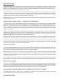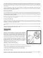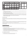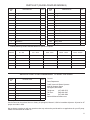
1
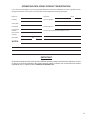
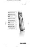
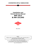
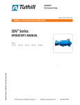
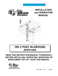
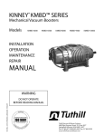
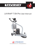
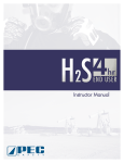
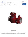
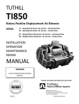
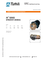
KINNEY®
Axial Flow, Liquid Ring Vacuum Pump
Manual 1862-2 0315 ENG
WARNING: Do Not Operate Before Reading Manual
AF™ SERIES
OPERATOR’S MANUAL
Models
A5
A10
A15
A20
A75
A100
A130
A200
A300
A600
T0505
T1505
T2010
T7530
T10030
Operator’s Manual: Tuthill AF™ Series Liquid Ring Vacuum Pumps
Single Stage Series
Two Stage Series
Tuthill Vacuum & Blower Systems
tuthillvacuumblower.com
800.825.6937
WARNING
CAUTION
DO NOT VALVE OR RESTRICT PUMP
DISCHARGE OPENING.
USE OIL MIST ELIMINATOR WHEN
OPERATING PUMP, ENSURE ADEQUATE
VENTILATION WHEN DISCHARGING INDOORS
DO NOT OPERATE
WITHOUT BELT
GUARD
REFER TO MANUAL SAFETY INSTRUCTIONS.
NOTICE
The above safety instruction tags were permanently affixed to your pump prior to shipment.
Do not remove, paint over or obscure in any manner.
Failure to heed these warnings could result in serious bodily injury
to the personnel operating and maintaining this equipment.
SAFETY PRECAUTIONS FOR LIQUID RING PUMPS
Please read the following safety information on this page before operating your vacuum pump.
•
Do not operate the pump without the coupling and belt guard properly attached. Disconnect the pump motor from the electrical supply at
the main disconnect before removing the belt guard. Replace the belt guard before reconnecting the power supply to the pump motor.
Operating the pump without the belt guard properly installed exposes personnel in the vicinity of the pump to risk from rotating drive
components.
CAUTION: Do not operate the pump with oxygen-enriched gas in the suction line, unless the pump has been properly cleaned,
inspected and certified to be free of hydrocarbon presence and prepared with an inert fluid suitable for the application.
•
Oxygen-enriched gas is defined as gas of which the constituents include by volume (mol. %) an amount of oxygen greater than that of
standard atmospheric air (typically 20-21% by volume).
•
If the oxygen content in the gas stream exceeds the proportions found in standard atmospheric air, then it is considered an oxygenenriched gas and standard mineral oil, synthetic hydrocarbon oil or other non-inert fluids should not be used.
WARNING: Pumping oxygen-enriched gases with mineral oil, synthetic hydrocarbon oil or other non-inert fluids can cause fire or
explosion in the pump, resulting in damage or serious bodily injury or death.
•
Take precautions to avoid prolonged or excessive exposure to oil mist or process materials emanating from the discharge of the pump.
•
Do not allow the pump to discharge into a closed, or inadequately ventilated room. Always use a discharge oil mist eliminator unless
the pump discharge is discharged to outside atmosphere. Laws and ordinances may pertain to your local area regarding discharge of
oil mist or vapor to atmosphere. Check local laws and ordinances prior to operation of the pump with discharge to outside atmosphere.
•
Venting of the discharge of an oil mist eliminator to outside atmosphere is highly recommended.
•
Do not restrict the pump discharge in any way, or place valves in the discharge line. The vacuum pump is a compressor and will generate
high pressures without stalling the motor when operated at low suction pressures. Excessive pressure could cause pump damage or
serious bodily injury.
•
Disconnect the pump motor from the electrical supply at the main disconnect before disassembling or servicing the pump. Make sure
pump is completely reassembled, the belt guard is properly installed, and that all fill and drain valves are installed and closed before
reconnecting the power supply. Accidental starting or operation of the pump while maintenance is in progress could cause pump
damage or serious bodily injury.
•
Lift pump only by the lifting lugs supplied with the pump. DO NOT lift equipment attached to pump by the pump lifting lugs.
•
Do not touch hot surfaces on the pump. In normal operation at low pressures, surface temperatures will not normally exceed 180° F (82°
C). Prolonged operation at 200 Torr (267 mbar a) may cause surface temperatures as high as 220° F (104° C)
2
TABLE OF CONTENTS
SECTION
INTRODUCTION
PAGE
4
LIQUID RING VACUUM PUMPS — PRINCIPLE OF OPERATION
4
SPECIAL FEATURES
4
SERVICE AND PARTS
4
SAVE WATER, TIME AND MONEY WITH AF SEALANT RECOVERY SYSTEMS
4
THE BASIC SYSTEM
5
HEAT EXCHANGERS
5
OTHER ALTERNATIVES
5
INSTALLATION
5
LOCATION
5
GENERAL PIPING INSTRUCTIONS
5
VACUUM INLET PIPING
5
DISCHARGE PIPING
6
SEAL WATER PIPING
6
ELECTRICAL CONNECTIONS
6
OPERATION
6
SEAL WATER REQUIREMENTS
6
STARTUP
7
STOPPING PUMP
7
MAINTENANCE
7
TROUBLESHOOTING
7
PUMP WILL NOT TURN ON STARTUP
7
NO PUMPING ON STARTUP
7
POOR PUMP PERFORMANCE; LOW VACUUM
8
PUMP UNUSUALLY NOISY
8
HIGH AMPS
8
SERVICE AND REPAIR
8
ASSEMBLY AND DISASSEMBLY INSTRUCTIONS
8-9
EXPLODED VIEW DRAWINGS AND PARTS LISTS
10-13
WARRANTY – VACUUM PRODUCTS
14
3
INTRODUCTION
CONGRATULATIONS on your purchase of a new AF axial flow liquid ring vacuum pump from Tuthill Vacuum & Blower Systems.
Please examine the pump for shipping damage, and if any damage is found, report it immediately to the carrier. If the pump is to be
installed at a later date make sure it is stored in a clean and dry location and make sure covers are kept on all openings. If pump is
stored outdoors be sure to protect it from weather and corrosion.
AF liquid ring vacuum pumps are built to exacting standards and if properly installed and maintained will provide many years
of reliable service. We urge you to take time to read and follow every step of these instructions when installing and maintaining
your pump. We have tried to make these instructions as straightforward as possible because we realize getting any new piece of
equipment up and running as quickly as possible is imperative to production.
WARNING: Serious injury can result from operating or repairing this machine without first reading the service manual and taking
adequate safety precautions.
LIQUID RING VACUUM PUMPS — PRINCIPLE OF OPERATION
The liquid ring vacuum pump removes gases by means of an impeller rotating freely in an eccentric casing. The pumping is done
by a liquid, usually water, that is fed into the pump and thrown by centrifugal force into a moving ring along the casing or cover wall.
When gas or vapor enters the suction port, it is trapped by the whirling impeller blades and a liquid piston that expands in the
eccentric lobe of the casing. As the impeller rotates, the liquid is then pushed inward by the narrowing space between rotor and
casing, compressing the trapped pocket of gas. Finally the compressed gas is released through a discharge port as the impeller
completes the revolution.
The direct contact between the liquid ring and the gas makes the pump ideal for wet applications and for handling condensibles that
are discharged with the gas and liquid. Unlike rotary vane and piston pumps, the operation of a liquid ring vacuum pump is nearly
isothermal and without vibration. There is no oil to be changed or pollutant released into the environment. Because there are no
valves and no rubbing parts, a liquid ring pump is virtually maintenance free.
With liquids other than water, vapor pressure in the pump can be reduced for high vacuum or compatibility achieved with specific
process gases. In some cases, distillate or another fluid is introduced directly into the suction pump inlet and used as the liquid seal.
Liquid ring pumps are also commonly staged with positive displacement blowers, air and steam ejectors for greater capacity and/or
deeper vacuum. Tuthill Vacuum & Blower Systems offers many such staged units, including its patented AF two-stage system with
rotary blower, liquid ring back up and unique fluid coupling design.
SPECIAL FEATURES
One of the distinguishing features on an AF pump is an axial flow design that permits the widest range and highest vacuum of any
single-stage liquid ring pump. A fixed port cylinder concentric with the rotor bore directs the gas along the shaft axis, into the suction
ports of the rotor, and finally back through the rotor and rear of the pump for discharge.
Because the gas flow is along the motor shaft (and not at right angles), the pump can start in a flooded state without damage and
has excellent water handling capacity. The use of a shrouded rotor also increases pumping efficiency for high vacuum and low water
consumption. The pump head, close-coupled to a NEMA C-face motor, is extremely compact and requires no interstage manifold as
do older style radial flow pumps.
Further advantages to AF pumps include the use of modern O-Rings and mechanical Seals rather than gaskets and stuffing boxes,
and a replaceable port cylinder for fast in-the-field repair. Available in all bronze, cast iron, stainless steel and other special materials.
SERVICE AND PARTS
AF pumps are 100% designed and manufactured in the United States. All parts are maintained in inventory for immediate shipment
from our factory in Springfield, MO. At the back of this manual is a list of parts and recommendations for spares to keep on hand. The
reputation of Tuthill Vacuum & Blower Systems is staked on fast service and practical assistance in designing vacuum systems for
specific applications. Specializing in the liquid ring field, the company was created by and for ENGINEERS.
SAVE WATER, TIME AND MONEY WITH AF SEALANT RECOVERY SYSTEMS
In applications where water is costly, scarce, or unavailable, AF Sealant Recovery Systems provide simple, compact and
environmentally safe options for recirculating seal water and storing waste.
THE BASIC SYSTEM
4
The standard configuration for recirculating seal water is to pipe the pump discharge into a small separator tank where non-condensed
gas is vented into the atmosphere and the water is returned to the pump inlet. By having a tee connection in the inlet piping for the
return (rather than through the separate seal water inlet), the pump will draw its own water requirement controlled by a flow restrictor
in the return line.
The basic system offered by Tuthill Vacuum & Blower Systems is a completely self-contained pumping system that fits almost
anywhere for intermittent or low vacuum use. The package includes a close-coupled pump, baseplate, and a stainless steel separator
tank with complete seal water and discharge piping.
HEAT EXCHANGERS
For continuous high vacuum use, a heat exchanger is recommended to counter the temperature rise from the heat of compression.
Higher seal water temperatures will increase the partial vapor pressure inside the pump and limit high vacuum performance. Used
in conjunction with water chillers, refrigeration units, fan coils, or cooling towers; a properly sized heat exchanger will maintain seal
water temperatures for maximum performance.
Depending on the heat to be removed and cooling system available on location, Tuthill Vacuum & Blower Systems will specify or
furnish a heat exchanger sized for your application.
OTHER ALTERNATIVES
Among the other options for reusing liquid sealant are partial recirculation systems and specially packaged units using sealants other
than water (i.e. oil, solvents, etc.). In a partial recirculation loop, a certain amount of make-up water is fed into the pump to minimize
temperature rise, yet allow for substantial water savings.
For sealants other than water, be sure to consult Tuthill Vacuum & Blower Systems for assistance with both the pump and recirculation
sizing.
Tuthill Vacuum & Blower Systems invites you to inquire about specific, practical and inexpensive methods for reducing your operating
costs and for saving that precious natural resource - water.
INSTALLATION
LOCATION
Because of its close-coupled design, an AF pump is ideal for applications
where space is critical. Its vibration-free operation permits direct bolting to the
floor or mounting on a baseplate anywhere that is convenient for piping. The
standard motors furnished by TUTHILL Vacuum & Blower Systems on AF are
Totally Enclosed Fan Cooled (TEFC) suitable for areas where the motor may
be exposed to water. Special motors are available for hazardous locations.
The pump needs no adjustment, alignment or coupling, guard, etc., and because
the pump runs COOL, no special ventilation is necessary — or access for
checking sight glasses and oil. In choosing a location, the main consideration
should be the pump’s proximity to the vacuum system and convenience for
draining discharge and piping the seal water.
GENERAL PIPING INSTRUCTIONS
Figure 1. AF Axial Flow Design
The Inlet, Discharge, and Seal Water Piping require observance of three basic
rules:
A. Piping must be free of all welding shot, slag, and other foreign matter that could damage pump.
B. Piping must be supported independently to avoid stress on pump casing.
C. Piping should be of the same diameter as the pipe connections on pump.
VACUUM INLET PIPING
Inlet piping is a simple matter of connecting the pump to the vacuum system. Models A5 and T0505 have a 3/4” NPT connection.
Models A10, A15, A20, T1505 and T2010 have a 1” NPT connection on their covers for direct piping.
5
The larger pumps feature flange faces. An inlet check valve is recommended to prevent vacuum loss and backstreaming when the
pump shuts down. Avoid using spring loaded valves not designed for vacuum service. An optional vacuum gauge can be mounted
between the pump and check valve to measure inlet vacuum.
DISCHARGE PIPING
Depending on the application, there are a number of ways to handle the discharged liquid and gas. If there are no pollutants, the
simplest scheme is to discharge directly into a drain. An AF pump can carry up to a ten-foot discharge head providing the piping
from that height is pitched toward a drain or other receptacle. EXCESSIVE BACK PRESSURE CAN ADVERSELY AFFECT PUMP
PERFORMANCE.
A second method is to run the discharge through a mechanical separator removing water from the gas. Water contaminated by
sanitary waste or noxious gas may be recirculated as seal water or discharged into a sanitary sewer or tank. The nature of the
contaminant will determine how often recirculated water must be changed.
SEAL WATER PIPING
Unless liquid is pumped directly through the vacuum inlet connection, most applications require separate piping for seal water to
enter the pump. The seal water inlet is located directly below the vacuum inlet on the pump’s face.
Water, the most widely used liquid seal, can be piped directly from a tap or recirculated from a discharge separator tank. Be sure to
specify if seal liquids other than water are to be used and Tuthill Vacuum & Blower Systems will make recommendations regarding
compatibility of materials, power requirements, etc.
The following accessories are recommended:
1. Flow control valve (see Seal Water Requirements)
2. Solenoid valve (to shut off water when pumping stops)
3. Strainer (to prevent foreign matter from entering the
pump)
For more information about recirculating seal water,
consult Tuthill Vacuum & Blower Systems.
ELECTRICAL CONNECTIONS
Refer to the motor label or conduit box for correct wiring.
Most motors are three phase and will be damaged if
single phased. De-rating for 50 cycle operation at different
voltages is possible if specified on motor label. Otherwise,
refer questions to motor manufacturer or to Tuthill Vacuum
& Blower Systems.
NOTE: Be sure to jog motor before starting to insure
correct wiring and rotation.
Figure 2. Once-through Seal Water
(minimum pressure 10 PSIG)
OPERATION
SEAL WATER REQUIREMENTS
AF liquid ring pumps, because of their exclusive axial
flow design, have the ability to handle large amounts of
water and, unlike radial flow pumps, can start in a flooded
state without damage. Seal water flow is not critical and
the flow rates can be readily adjusted for a wide variety
of applications. For most applications, the optimum seal
water rates are given below:
The water supply can be regulated by either a flow restrictor
or manually by valve. The object is to balance performance
against water consumption and power. THE PUMP MUST
NEVER RUN DRY. The solenoid valve must be in an open
position for pumping.
6
Figure 3. Recirculated Seal Water
(Tee into Inlet) — See Page 5 for
additional information.
SINGLE
STAGE
PUMP
MODEL
A5
A10
A15
A20
A75
A100
A130
A200
A300
A600
0 - 10” Hg
(0 - 340 mbar g)
GPM
L/min
1
3.8
1.5
5.7
2.0
VACUUM RANGE
10 - 25” Hg
(340 - 840 mbar g)
GPM
L/min
> 25” Hg
(> 840 mbar g)
GPM
L/min
1.5
5.7
2.0 - 3.0
7.6 - 11.4
2.0
7.6
2.0 - 3.5
7.6 - 13.2
7.6
2.5
7.6
3.0 - 4.0
11.4 - 15.1
11.4
15.1
45.4
3.0
5.0
6
16
11.4
18.9
22.7
60.6
4.0 - 5.0
6.0 - 8.0
8.0 - 10.0
18-20
15.1 - 18.9
22.7 - 30.3
30.3 - 37.9
68.1-75.7
TWO STAGE
PUMP
MODEL
VACUUM RANGE
ALL RANGES
GPM
L/min
T0505
T1505
2.0 - 3.0
7.6 - 11.4
3.0 - 4.0
11.4 - 15.1
T2010
3.0
4.0
12
T7530
T10030
STARTUP
1. Once the pump is fully piped and wired for operation, be sure no foreign matter may enter and possibly damage the pump. Check
for welding shot, slag or other metal bits.
2. Before starting the pump, turn the motor shaft by hand to be sure it is free to rotate. On TEFC motors, you may turn the rear fan.
Some resistance during a full rotation is normal.
3. If a hard rub is experienced and the motor shaft will not turn, the pump should be checked internally for interference. As long as
the shaft can be turned by hand, the pump is operable.
4. A final check is to jog the motor, making sure water is introduced into the pump and that rotation is in accordance with the arrow
cast on the pump face. If no flow of air or vacuum reading is immediately apparent, rewire the motor accordingly. ROTATION
SHOULD BE COUNTER-CLOCKWISE WHEN YOU ARE FACING THE PUMP INLET.
5. The pump is now ready for operation.
STOPPING PUMP
Once the power is shut off, be sure water is stopped from entering the pump. A solenoid valve in the seal water line is recommended
to shut off flow simultaneously with cessation of pumping. An inlet check valve is recommended to prevent vacuum loss or back flow
to the system.
MAINTENANCE
As a general rule, maintenance is not required for AF pumps. Because there are no rubbing parts and with water acting as coolant
and lubrication during pumping, wear is minimized. It is recommended that the motor bearings be greased periodically in accordance
with NEMA recommendations. For further information refer to the Troubleshooting section.
To prevent foreign matter from entering the pump, a strainer is recommended for the seal water line and the usual precautions taken
in the pump inlet piping.
TROUBLESHOOTING
PUMP WILL NOT TURN ON STARTUP
1. Check wiring and power to pump.
2. Remove pump cover to check for anything that may be binding the rotor. Be sure that the rotor turns freely by hand.
3. On cast iron pumps, check for internal rust if pump has been left idle for a long period. Rust can build up to the point where
internal clearances are closed. Remove rust and reassemble.
4. In areas where there is hard water being fed into the pump, check for scale deposits that may hinder rotation. Scale should be
removed by acidizing, but consult the factory for recommended procedures.
5. If the motor fails to turn, isolate the motor from the pump and re-check the motor.
NO PUMPING ON STARTUP
1. Check pump rotation. It may be rotating in reverse. Rewire motor to correct.
2. Check seal water. Water must be fed continuously into the pump.
7
POOR PUMP PERFORMANCE; LOW VACUUM
1. Check vacuum pump while running by sealing off inlet piping and reading vacuum at the pump suction. If high vacuum is
achieved, look for leaks in the vacuum system. The pump capacity is a function of high vacuum performance and will conform
to the published performance curve at standard conditions. High seal water temperatures will lower the vacuum because of the
increase in vapor pressure. Altitude, barometric pressure, and gas temperature can also affect high vacuum performance.
2. If high vacuum is not achieved on blank-off, the problem lies in the vacuum pump. Poor pump performance can be caused by
the following:
a. Pump may not be getting enough water. Adjust water supply and observe for change in the performance.
b.
Internal parts may be worn. Remove cover/port cylinder assembly and check for wear on the port cylinder, rotor, and
cover lands. Most wear will be limited to the port cylinder which should slide easily into the rotor bore. Replace port cylinder if
necessary. You may also polish the port cylinder and rotor bore with a fine emery cloth for a smooth fit.
PUMP UNUSUALLY NOISY
1. Unusual continuing noise from the motor end is probably an indication that the motor bearings are bad. Remove cover and spin
rotor by hand. You should be able to detect bearing noise. If indicated, replace motor bearings.
2. Cavitation. The vacuum pump should not be operated on blank suction for any length of time. When liquid ring vacuum pumps
are starved for air, cavitation is indicated by a rattling noise and vibration in the pump. Cavitation can be eliminated by providing
slight air bleed into the vacuum system.
HIGH AMPS
1. Flooding the pump with too much water, particularly at low vacuum, can overload the motor. Adjust seal water supply.
2. Internal rubbing of rotor with stationary parts can cause excessive loading. Shut off pump and rotate by hand (see Startup
section) to see if rotor turns freely. Internal rubbing may be due to scale build-up, a galling foreign material or by misalignment
of parts. (see Troubleshooting section; specifically, paragraphs titled “PUMP WILL NOT TURN ON STARTUP” & “POOR PUMP
PERFORMANCE; LOW VACUUM.”
SERVICE AND REPAIR
AF liquid ring vacuum pumps are designed to minimize down time
by allowing for fast in-the-field repair. Time and money-saving
features include:
• Shaft mounted assembly for easy alignment and indicating.
• Modern O-rings and mechanical seals for practically zero
leakage and easy replacement.
• Replaceable port cylinder that unscrews from cover and
requires no special shimming or adjustment.
• Front end disassembly for fast access to major internal parts.
• American-made stock parts available for immediate
shipment.
DISASSEMBLY OF PUMP
The pump may be disassembled while bolted to the baseplate by
removing suction and seal water piping and working from cover to
motor. Most repair work will not require full disassembly, but please
refer to the exploded pump diagram in following these steps:
Figure 4. Cutaway View
1. Shut off all valves controlling flow of fluids to and from the
pump casing. Disconnect external piping.
2. Remove bolts connecting cover to casing. The cover and port cylinder assembly will slide straight outward. The port cylinder is
dismounted from cover by removing three socket head cap screws.
3. Remove hex head lock screw and washer from motor shaft. Use a bearing puller to remove rotor without damage to casing. Be
sure to protect the threaded shaft bore.
4. Slide shims and mechanical seal off shaft.
5. Unbolt casing from motor face.
6. Save any and all shims from shaft and casing assemblies for proper realignment.
8
ASSEMBLY OF PUMP
Before assembling of the pump, carefully inspect all parts for signs of unusual wear, abrasion, and corrosion. O-rings should be
checked for cracks or brittleness and the carbon face of the mechanical seal examined for scratches. Replace all parts as needed
and proceed as follows. NOTE: Numbers in parentheses refer to the drawing on page 10.
STEP 1 — SLEEVE AND SEAL ASSEMBLY:
The mechanical seal is composed of a seal seat (8a), seal (8b), and spring (8c). The seat is a ceramic ring with a rubber boot that is
pressed firmly into the rear of the casing. Lubricant is recommended for ease in inserting rubber boot in the seal housing bore. BE
VERY CAREFUL NOT TO SCRATCH THE CERAMIC FACE DURING HANDLING AND INSERTION.
Once the seal seat is in place, mount casing (1) on the motor face. The larger pump casings are mounted on four studs extending
from motor face, while the smaller casings (Models A5, A10, A15, A20, T0505, T1505, T2010) are secured by four hex head bolts.
It is seldom needed to replace the shaft sleeve. It can usually be polished using fine emery cloth. If the sleeve is to be replaced slip
the small O-ring (11) over shaft until it touches the shaft shoulder and place the sleeve/bushing (9) on top so that its chamfered end
presses against O-ring.
To complete the assembly, lubricate the sleeve so that the rest of the mechanical seal (#8b) can be pressed on with the carbon face
in flat sliding contact with the ceramic seat. Again, AVOID SCRATCHING OR TOUCHING THE CARBON FACE. Proper tension
between the seal faces is provided by the spring - leading to Step 2.
STEP 2 — ROTOR ASSEMBLY AND ALIGNMENT:
The rotor is secured to the shaft by means of a key (15), a hex head lock screw
(13), and a washer (14). Lower the rotor onto the shaft key, making sure to align
the notch with the shaft key. In order for the rotor to turn freely, there must be
some clearance between it and the casing. On Models A5, A10, A15, A20, T0505,
T1505 and T2010, this clearance is established by adding washer shims (10) until
no rub is felt between the back of the rotor and the casing face. On the Models
A75, A100, A130, T7530, T10030, shims are used to position the rotor so that
the casing face lines up with the inside wall of the rotor shroud. (See photograph
below).
Be sure to use a bearing puller when removing rotor to add more shims. Avoid
damage to the casing face and to the threaded shaft bore. Once secured, the
rotor should spin freely without any interference or rub from the casing.
Figure 5. Rotor Assembly
To ensure proper alignment, you may indicate the run-out on the front edge of the rotor. Using a dial indicator measure the run-out on
the rotor. It should be within .003 - .005 inches (.08 - .13 mm). Tightening down the rotor is facilitated by using a long bolt and several
washers before inserting the lock bolt.
STEP 3 — PORT CYLINDER ASSEMBLY AND COVER:
The port cylinder (3) is readily mounted on the cover (4) by three socket head cap screws with nylon patches (6). A fiber gasket (5) is
used to seal the surface between the cover and port cylinder while the alignment of tapped holes insures correct placement.
The final assembly step is to grease and stretch the O-ring and then insert it into a greased cover groove. Then slide the port cylinder/
cover assembly into the rotor bore.
The surface where cover and casing meet will be sealed by the O-ring. In securing the cover to the casing, the cover bolts (19)
must be drawn up uniformly. During tightening, the rotor should be turned by hand to insure easy rotation when the pump is fully
assembled. Loosen the bolts and then tighten again if a hard rub is experienced.
NOTE: Models A75, A100, and A130 have two socket head bolts which should be used in the bottom cover holes.
After the drain plugs (17, 18) have been installed with Teflon® tape on the threads, the vacuum pump is ready for service.
9
CLOSE-COUPLED PUMP
EXPLODED VIEW
10
PARTS LIST (CLOSE-COUPLED MODELS)
ITEM
NO.
DESCRIPTION
QTY
ITEM
NO.
DESCRIPTION
QTY
1
Casing
1
11
O-ring, Shaft
1
2
Rotor
1
12
O-ring, Cover
1
3
Port Cylinder
1
13
Lock Bolt
1
4
Cover
1
14
Washer
1
5
Gasket
1
15
Key
1
6
Cap Screws
3
16
Slinger
1
7
Motor
1
17
Drain Plug, Cover
1
8
Mechanical Seal Assembly consisting of:
1
18
Drain Plug, Casing
1
8a
Seat
1
19
Cover Bolts, Hex Head
**
8b
Seal
1
19a
Cover Bolts, Socket Head
**
8c
Spring
1
20
Casing Bolts
**
9
Shaft Sleeve
1
20a
Casing Studs
**
10
Shim
3
20b
Casing Nuts
**
** - Quantity differs by model. See table below for quantities required.
ITEM NO.
A5 - A20
A75 - A130
A200 - A300
T0505 - T2010
T7530 - T10030
19
4
4
6
—
—
19a
—
2
—
4
6
20
4
—
—
4
—
20a
—
4
4
—
4
20b
—
4
4
—
4
SERVICE PARTS RECOMMENDED TO KEEP ON HAND
ITEM
NO.
DESCRIPTION
QTY
3
Port Cylinder
1
5
Gasket
1
8
Mechanical Seal Assembly
1
10
Shim
3
11
O-ring, Shaft
1
12
O-ring, Cover
1
13
Lock Bolt
1
Contact:
Parts Department
Tuthill Vacuum & Blower Systems
4840 W. Kearney Street
Springfield, MO 65803
Telephone: (417) 865-8715
Toll Free: (800) 825-6937
Fax: (417) 865-2950
www.tuthillvacuumblower.com
Service Parts can be ordered from our factory in Springfield, Missouri, USA for immediate shipment. All parts for AF
pumps are made in USA.
We are happy to assist you with any questions that may arise and to provide advice on applications for your AF pump.
Please do not hesitate to contact us.
11
A-600 EXPLODED VIEW DRAWING AND PARTS LIST
280
250
240
290
300
130
80
70
230
10
190
260
40
270
60
30
150
170
ITEM
NO.
10
20
30
40
50
60
70
80
120
130
140
150
170
190
230
240
250
260
270
280
290
300
120 170
60
130
20
DESCRIPTION
PEDESTAL CASING
ROTOR
PORT CYLINDER
COVER
PORT CYLINDER GASKET
HBOLT 0.3750-16X0.75X0.75-C
SHAFT
MECHANICAL SEAL ASSY
COVER O-RING
HBOLT 0.6250-11X1.5X1.5-C
WASHER FW 0.625
KEY B17.1 0.625X0.625X1.5
PIPE PLUG, HEX SOCK 1”
HBOLT 0.6250-11X1.75X1.75-C
DPM 0.5X1.5
NOSE O-RING
NOSE COVER
END PLATE
DRIVE BEARING
PUMP BEARING
BEARING LOCK NUT
HBOLT 0.3750-16X1X1-C
140
50
QTY.
1
1
1
1
1
7
1
1
1
2
2
1
2
12
2
1
1
1
1
1
1
5
NOTES:
13
WARRANTY – VACUUM PRODUCTS
Subject to the terms and conditions hereinafter set forth and set forth in General Terms of Sale, Tuthill Vacuum & Blower
Systems (the Seller) warrants products and parts of its manufacture, when shipped, and its work (including installation and
start-up) when performed, will be of good quality and will be free from defects in material and workmanship. This warranty
applies only to Seller’s equipment, under use and service in accordance with Seller’s written instructions, recommendations
and ratings for installation, operating, maintenance and service of products, for a period as stated in the table below.
Because of varying conditions of installation and operation, all guarantees of performance are subject to plus or minus 5%
variation. (Non-standard materials are subject to a plus or minus 10% variation).
PRODUCT TYPE
WARRANTY DURATION
New
15 months after date of shipment or 12 months after initial startup date, whichever occurs first
Piston Pumps
30 months after date of shipment, on all units sold after June 1, 2014.
Repair
6 months after date of shipment or remaining warranty period, whichever is greater
Remanufactured
9 months after date of shipment or 6 months after initial startup date, whichever occurs first
THIS WARRANTY EXTENDS ONLY TO BUYER AND/OR ORIGINAL END USER, AND IN NO EVENT SHALL THE
SELLER BE LIABLE FOR PROPERTY DAMAGE SUSTAINED BY A PERSON DESIGNATED BY THE LAW OF ANY
JURISDICTION AS A THIRD PARTY BENEFICIARY OF THIS WARRANTY OR ANY OTHER WARRANTY HELD TO
SURVIVE SELLER’S DISCLAIMER.
All accessories furnished by Seller but manufactured by others bear only that manufacturer’s standard warranty.
All claims for defective products, parts, or work under this warranty must be made in writing immediately upon discovery
and, in any event within one (1) year from date of shipment of the applicable item and all claims for defective work must be
made in writing immediately upon discovery and in any event within one (1) year from date of completion thereof by Seller.
Unless done with prior written consent of Seller, any repairs, alterations or disassembly of Seller’s equipment shall void
warranty. Installation and transportation costs are not included and defective items must be held for Seller’s inspection and
returned to Seller’s Ex-works point upon request.
THERE ARE NO WARRANTIES, EXPRESSED, IMPLIED OR STATUTORY WHICH EXTEND BEYOND THE DESCRIPTION
ON THE FACE HEREOF, INCLUDING WITHOUT LIMITATION, THE IMPLIED WARRANTIES OF MERCHANTABILITY
AND FITNESS OF PURPOSE.
After Buyer’s submission of a claim as provided above and its approval, Seller shall at its option either repair or replace its
product, part, or work at the original Ex-works point of shipment, or refund an equitable portion of the purchase price.
The products and parts sold hereunder are not warranted for operation with erosive or corrosive material or those which may
lead to build up of material within the product supplied, nor those which are incompatible with the materials of construction.
The Buyer shall have no claim whatsoever and no product or part shall be deemed to be defective by reason of failure to
resist erosive or corrosive action nor for problems resulting from build-up of material within the unit nor for problems due to
incompatibility with the materials of construction.
Any improper use, operation beyond capacity, substitution of parts not approved by Seller, or any alteration or repair by
others in such manner as in Seller’s judgment affects the product materially and adversely shall void this warranty.
No employee or representative of Seller other than an Officer of the Company is authorized to change this warranty in any
way or grant any other warranty. Any such change by an Officer of the Company must be in writing.
The foregoing is Seller’s only obligation and Buyer’s only remedy for breach of warranty, and except for gross negligence,
willful misconduct and remedies permitted under the General Terms of Sale in the sections on CONTRACT PERFORMANCE,
INSPECTION AND ACCEPTANCE and the PATENTS Clause hereof, the foregoing is BUYER’S ONLY REMEDY
HEREUNDER BY WAY OF BREACH OF CONTRACT, TORT OR OTHERWISE, WITHOUT REGARD TO WHETHER ANY
DEFECT WAS DISCOVERED OR LATENT AT THE TIME OF DELIVERY OF THE PRODUCT OR WORK. In no event
shall Buyer be entitled to incidental or consequential damages. Any action for breach of this agreement must commence
within one (1) year after the cause of action has occurred.
June 2014
14
OPERATING DATA FORM / PRODUCT REGISTRATION
It is to the user’s advantage to have the requested data filled in below and available in the event a problem should
develop in the blower or the system. This information is also helpful when ordering spare parts.
Model No.
V-Belt Size
Serial No.
Type of Lubrication
Length
Startup Date
Pump RPM
Operating Vacuum
Pump Sheave
Diameter
Any other Special Accessories Supplied or in use:
Motor Sheave
Diameter
Motor RPM
HP
NOTES:
IMPORTANT
All blowers manufactured by Tuthill Vacuum & Blower Systems are date coded at time of shipment. In order
to assure you of the full benefits of the product warranty, please complete, tear out and return the product
registration card, or register online at tuthillvacuumblower.com.
15
For Service & Repair, Technical Support,
or Product Sales contact:
T
REGIS ERED
VACUUM & BLOWER SYSTEMS
D
TUTHILL CORPORATION
T
ER
AR
IN
16
Tuthill Vacuum & Blower Systems
4840 West Kearney Street
Springfield, Missouri USA 65803-8702
O 417.865.8715 800.825.6937 F 417.865.2950
tuthillvacuumblower.com
NA
TIO
N A L Q U A LIT Y S
N
TA
D
Manual 1864-2 0315 ENG