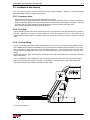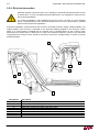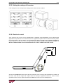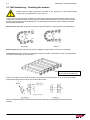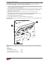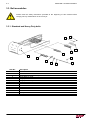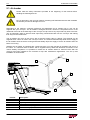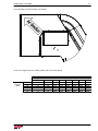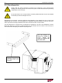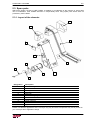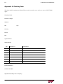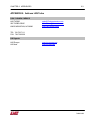
1
Instruction Manual
LNS Turbo
203 Turbo Drive
Kings Mountain, NC 28086
ENG
V1.00
TABLE OF CONTENTS
CHAPTER 1: INTRODUCTION................................................................................... 1-1
1.1 Basic introduction ............................................................................................................................ 1-2
1.1.1. Symbols and terminology ................................................................................................... 1-2
1.2. Rights ................................................................................................................................................ 1-3
1.3. Characteristics ................................................................................................................................ 1-4
1.3.1. Floor plans .................................................................................................................................. 1-4
CHAPTER 2: SETTING INTO OPERATION .......................................................... 2-1
2.1. Transportation ..................................................................................................................................2-2
2.2. Unpacking ........................................................................................................................................ 2-2
2.3. Lifting the conveyor ........................................................................................................................ 2-3
2.4. Safety devices ................................................................................................................................. 2-3
2.4.1. Description .................................................................................................................................. 2-4
2.4.2. Layout of the safety elements on the conveyor (Top mount drive version shown) ..................... 2-4
2.4.3. Installation safety ........................................................................................................................ 2-5
2.4.4. Security analysis for the correct incorporation ............................................................................ 2-6
2.5. Installation and startup ................................................................................................................... 2-7
2.5.1. Conveyor drive ............................................................................................................................ 2-7
2.5.2. Leveling....................................................................................................................................... 2-7
2.5.3. Coolant filling ............................................................................................................................... 2-7
2.5.4. Electrical connection ................................................................................................................... 2-8
2.5.5. Setting the voltage of the motor .................................................................................................. 2-9
2.5.6. Electrical control .......................................................................................................................... 2-9
2.5.7. Pre-start check .......................................................................................................................... 2-10
CHAPTER 3: CONVEYOR BELT .................................................................................. 3-1
3.1. Belt tensioning – Checking the tension ........................................................................................ 3-2
3.2. Belt tensioning – How to tension the belt ................................................................................. 3-3
3.3. Belt assemblies ............................................................................................................................... 3-4
3.3.1. Standard and Heavy Duty belts ................................................................................................. 3-4
3.3.2. Super Heavy Duty belts ........................................................................................................................................................................ 3-5
3.3.3. Lower conveyor – Scraper belt parts .......................................................................................... 3-6
CHAPTER 4: MAINTENANCE ................................................................................... 4-1
4.1. Periodic inspection ........................................................................................................................ 4-2
4.1.1. After first 100 hours ............................................................................................... 4-2
4.2. Cleaning ........................................................................................................................................... 4-3
4.3. Factors affecting performance................................................................................................... 4-3
TURBO MF3
CHAPTER 5: OPTIONS.......................................................................................................... 5-1
5.1. Air header ........................................................................................................................................................ 5-2
5.2. Chip stripper bar ............................................................................................................................................. 5-4
5.3. Spare parts ...................................................................................................................................................... 5-5
5.3.1. Layout of the elements .............................................................................................................................. 5-5
CHAPTER 6: APPENDICES ...................................................................................................... 6-1
Appendix A: Ordering form................................................................................................................................... 6-2
Appendix B: Address LNS .................................................................................................................................... 6-3
TURBO MF3
CHAPTER 1: INTRODUCTION
1-1
CHAPTER 1:
INTRODUCTION
TURBO MF3
1-2
CHAPTER 1: INTRODUCTION
1.1 Basic introduction
LNS conveyors simply and reliably remove waste from machining operations. Machine efficiency is
increased and operator safety is improved since the conveyors work with little operator attention and
without interrupting production time. LNS Turbo conveyors are available for many types of machine tools or
other applications. They can be arranged to deliver wet or dry waste to containers or to conveyor or
chute-type disposal systems. For further information, contact LNS.
The TURBO MF3 conveyor was specifically designed for applications where mixed chips are
produced. The dual conveyor system with filtering drum ensures that both long and small chips are
evacuated from the conveyor discharge.
The filtering drum provides self-cleaning filtration to 50 Micron. The drum is automatically rotated by the
lower conveyor chain. A back wash pump continually cleans the drum with no intervention required by the
machine operator. The 50 Micron filtration means that the coolant tank is kept clean from small chips thus
extending the time required between tank cleanouts. The 50Micron filtration also ensures cleaner coolant
delivery from the machine pumps helping to improve machining efficiency.
Combining high technology and user friendliness, it offers users a surprisingly vast number of
applications, while remaining simple to use and highly reliable. Given its compact assembly, TURBO
MF3 requires very little space, and allows for optimum use of the work surface.
1.1.1. Symbols and terminology
This sign recommends following the directions very closely avoiding causing an incident
that could result in injury, damage to the equipment, or data loss.
This sign indicates that safety measures must be taken to avoid possible electrical shocks
or mishaps.
This sign stress interesting points or comments, and provide useful advice for optimal
system operation.
TURBO MF3
CHAPTER 1: INTRODUCTION
1-3
1.2. Rights
All rights reserved. Reproduction, recording or transmission of all, or any portion, of this manual, in any form
or through any means whatsoever, whether mechanical, photographic, sound or other, without the express
written authorization of LNS Turbo, is prohibited. LNS Turbo disclaims all responsibility for errors which may be
contained in this manual and the problems which may result therefrom.
LNS Turbo and its subsidiaries cannot be made responsible for the debts, losses, expenses, or damage
incurred, or suffered, by the buyer of this product, or a third party, following an accident, incorrect use, or
misuse, or stemming from modifications, repairs, or transformations not authorized by LNS Turbo.
LNS Turbo and its subsidiaries cannot be held responsible for damage and problems arising from the use of
options and products other than LNS products, or products approved by LNS Turbo.
The names of the products indicated in this manual are registered trademarks.
All information contained in this manual is intended to be correct, however information and data in this
manual are subject to change without notice. LNS Turbo makes no warranty of any kind of regard to this
information or data. Further, LNS Turbo is not responsible for any omissions or errors or consequential
damage caused by the user of the product. LNS Turbo reserves the right to make manufacturing changes
which may not be included in this manual.
LNS Turbo supplies data necessary for the proper instruction, test, operation and maintenance of this
product. LNS Turbo retains all proprietary rights in and to the information so disclosed and such shall not be
reproduced, copied, or used in whole or in part for purposes other than those for which it is furnished.
TURBO MF3
1-4
CHAPTER 1: INTRODUCTION
1.3. Characteristics
Depending on the country and the standards in effect, certain technical data, such as the
power supply, may vary. Please see the technical card delivered with the device.
Type
Belt
Belt width
W-Width
T-Height
L-Leg location
Filtration
Flow rate
Standard duty
19mm (0.75")
102 - 559mm (4 - 22")
BW +54mm (+2.06")
260mm (10.23")
325mm (12.80")
50 µ standard
up to 575 l/min
Heavy duty
25mm (1.00")
102 – 610mmm (4-24")
BW +93mm (+3.63")
274mm (10.80mm)
325mm (12.80")
50 µ standard
up to 575 l/min
Super heavy duty
38mm (1.50")
102 -914mm (4-36")
BW +99mm (+3.88")
271mm (10.67")
325mm (12.80")
50 µ standard
up to 575 l/min
1.3.1. Floor plans
Each conveyor varies in size depending on the machine tool it is designed to fit to. Below is a general
diagram which can be used to help in communications with LNS Turbo regarding size queries and inquiries.
Drawing
dimension
A
B
C
D
E
F
G
H.
I
J
K
L
M
TURBO MF3
Conveyor terminology<
Baffle width
Frame height
Baffle height
Frame width
Baffle length
Covered load
Tail height
Load length
Overall length
Conveyor difference in height
Height above floor
Discharge height
Overall height
CHAPTER 2: SETTING INTO OPERATION
2-1
CHAPTER 2:
SETTING INTO OPERATION
TURBO MF3
2-2
CHAPTER 2: SETTING INTO OPERATION
2.1. Transportation
Please read the safety precautions described at the beginning of this manual before
handling the following devices.
Depending on its destination, the conveyor is normally secured to a pallet then heat sealed inside a
protective plastic cover. All shipping documents including this manual are also secured to the pallet.
Regardless of the type of packaging, the un-creating and lifting instructions recommended by LNS Turbo
must be observed in order to prevent any injuries to persons and damages to objects.
2.2. Unpacking
For practical and safety reasons, the conveyor must be unpacked in a spacious, well-lit location.
Check to see that the lifting capacity of the hoisting crane, or lift truck, is adequate before
proceeding with the handling of the merchandise. No one should be near the hanging load,
or within the operating range of the overhead hoist/crane, forklift, or any other means used
for lifting and transportation.
1)
If the conveyor is received as shown below start by removing the protective plastic material
2)
Cut any steel banding used to secure the conveyor to the pallet using side cutters (always wear
eye protection and gloves)
3)
Remove any screws holding the conveyor to the pallet (these may go through jacking or castor
plates.
TURBO MF3
CHAPTER 2: SETTING INTO OPERATION
2-3
2.3. Lifting the conveyor
Check to see that the lifting capacity of the hoisting crane, or lift truck, is adequate before
proceeding with the handling of the merchandise. No one should be near the hanging load,
or within the operating range of the overhead hoist/crane, forklift, or any other means used
for lifting and transportation.
Lifting points are strategically placed around the conveyor system to allow the conveyor to be safely lifted
with a fork truck or lifting straps. Otherwise points under the tank are marked with arrows (as shown
below) for safe, balanced, lifting points for fork trucks to lift the conveyor system and tank assembly.
Always read the weight on the conveyor and check it against the capacity of the lifting equipment before
attempting to lift:
Safe marked lifting
points
for
the
conveyor system.
TURBO MF3
2-4
CHAPTER 2: SETTING INTO OPERATION
2.4. Safety devices
The LNS Company, or its local representative, may not be held responsible for possible
accidents or property damage, whether caused directly or not, by any means whatsoever,
if certain safety devices have not been included.
2.4.1. Description
The TURBO MF3 conveyor has been designed with a focus on maximum safety during its handling
and complies with all EC requirements. Safety covers and devices make access to the moving parts of
the conveyor impossible during operation. The conveyor – machine interface must ensure that the
conveyor cannot run when the machine door is open. All safety interlocks on the conveyor or machine
must not be over written at any time. By pressing the emergency stop button located on the machine, the
functions of the lathe and conveyor are immediately stopped. W hen integrated to the machine it is
important that the discharge area of the conveyor is well protected and not exposed to persons. A
suitable Emergency stop cord should be integrated around the discharge of the conveyor to allow the
emergency stop circuit to be activated from the conveyor discharge area.
Only those who know the product and are sufficiently qualified are able to install, set into operation,
maintain and fix the conveyor. The customer must ensure that internal arrangements regarding
supervising the prescribed indications of the events, of work organization and staff competence is
available with the assembly instructions.
All persons who perform work on this machine must have read and understood the assembly instructions.
2.4.2. Layout of the safety elements on the conveyor (Top mount drive version shown)
7
1
1
2
6
3
It’s recommended
that an emergency
stop rope or suitable
guarding protecting
the discharge is
fitted.
5
8
4
Designation
1
2
3
4
5
6
7
8
TURBO MF3
Description
Drive cover
Top cover upper curve
Top cover incline upper curve
Top cover incline lower curve
Top cover load
Bearing cover
End cover discharge
Drum access window
CHAPTER 2: SETTING INTO OPERATION
2-5
2.4.3. Installation safety
In order to ensure the proper installation of the conveyor several steps must be taken. These steps are
listed below. It is possible to purchase these parts from LNS if required. Speak to your local LNS
representative for further details:
1) Suitable guarding must be used between the waste receptacle and the conveyor to ensure no
access to the moving belt is possible when the receptacle is in place (labeled 4 below). It is
recommended to utilize an interlock between the two components to stop the belt when the
receptacle is removed. In case any part of the belt is accessible then an emergency stop cord
around the discharge of the conveyor must be integrated to the machine tools emergency stop
circuit where the conveyor and machine are stopped immediately if the cord is pulled (labeled 1
below)
2) Suitable guarding must be installed around the area where the conveyor fits to the machine to
ensure that no conveyor belt is exposed to the customer. (Labeled 2 below).
3) A suitable waste receptacle must be utilized with the conveyor to ensure a proper fit to the conveyor
dimensions and working conditions (Labeled 3 below)
4) The conveyor must be integrated to the machines control circuit in such a way that the conveyor
belt cannot run when the machine door is opened. (Labeled 5 below).
5) Suitable warning signs must be placed at the danger zones of the conveyor such as the discharge
area to warn personnel of risk of injury.
Machine
Conveyor
1
4
5
2
3
TURBO MF3
2-6
CHAPTER 2: SETTING INTO OPERATION
2.4.4. Security analysis for the correct incorporation
Before considering assembling the machine, it is necessary to consider the following points::
Consider security strategies that reduce risks to an acceptable level;
Define the tasks required for applications to predict and assess the need of access and / or for
the approach;
Identify sources of risks, including failures and failure modes associated with each task. Risks
can come from:
o machine in which the device is integrated;
o its association with other equipment,
Evaluate and assess the risks associated by using the machine
o programming risks
o operation risks
o risks of use
o maintenance risks
Choose methods of protection :
o the use of protective devices
o the introduction of signals
o compliance with safe work procedures
TURBO MF3
CHAPTER 2: SETTING INTO OPERATION
2-7
2.5. Installation and startup
Your Conveyor has been run prior to shipment to insure proper operation. However, it is recommended
that the following checks be made before startup:
2.5.1. Conveyor drive
Check frame and belt for damage during shipment or storage.
Locate conveyor in operating position inside the machine (see separate specific interface instructions).
All drive elements (pulleys and sprockets) should be located close to their bearing supports. Each set
of pulleys and sprockets should be carefully aligned to prevent excessive wear and noise.
Drive chains and belts should be properly tensioned.
2.5.2. Leveling
A level should be placed across tail section and on the conveyor belt in line with the direction of travel of
the belt. Adjust the conveyor or tanks castors to ensure the system is level. If the system is not
equipped with leveling castors or jacking screws then it may be necessary to shim the system to make it
level.
2.5.3. Coolant filling
Fill the coolant tank with water soluble coolant solution of your choice. If neat oil is used please consult
LNS TURBO as the flow rate capabilities of the conveyor may be affected. After initial start-up, you may
find it necessary to add coolant to restore the desired fluid level. This is because the conveyor load
section acts as an additional reservoir and complete drain down of the conveyor does not occur even
during
system idle periods. Note: Do not fill the coolant tank level with coolant above the center line of the filter
drum (see below).
Prior to installation of the TURBO MF3, the coolant tank should be cleaned of any chip or dust residue
that may be present from shipping, storage or manufacture. This will ensure a clean and trouble free
start-up and prevent unnecessary cleaning at a later stage.
x
X = maximum fill level
TURBO MF3
2-8
CHAPTER 2: SETTING INTO OPERATION
2.5.4. Electrical connection
Particular attention should be given to the handling of electrical elements because of risks
of electrocution. In case of possible electrical malfunctions, it is advisable to contact LNS or
their local representative.
It is strictly prohibited to make adjustments as long as the conveyor is under electrical
power. The adjustments of the electrical equipment must only be performed by qualified
personnel in line with local regulations.
During the installation, ensure that the motor is wired in accordance with the supply voltage available. The
supply voltage of the conveyor is indicated on the electrical drawing supplied in the conveyors control
panel. If no control panel is supplied then the voltage can be checked directly at the conveyor motor
terminal box as shown below in section 2.5.5. Even if the electrical drawing is correct to the machines
requirements the conveyor motor should be checked to ensure the voltage setting is correct to prevent
possible damage.
5
6
7
8
2
1
3
4
Designation
1
2
3
4
5
6
7
8
TURBO MF3
Description
Motor terminal box upper conveyor
Cable from control box to upper conveyor motor
Terminal box back wash pump motor
Cable from control box to back wash pump motor
Control box
Motor terminal box lower conveyor
Cable from control box to lower conveyor motor
Cable from control box to be connected to the machine
CHAPTER 2: SETTING INTO OPERATION
2-9
2.5.5. Setting the voltage of the motor
If the voltage does not correspond, the wiring of the motor must be modified:
2.5.6. Electrical control
Your conveyor may or may not be supplied with an electrical control depending on the machine and
applications’ requirements. If an electrical control is supplied then please see the electrical drawing inside
the control panel for specific details. If any faults with the conveyor control occur or further information is
required please consult your local LNS agent.DO NOT DRILL HOLES IN CONVEYOR FRAME TO
MOUNT POWER BOXES OR ACCESSORIES WITHOUT FIRST CONSULTING LNS TURBO.
Arrows show forward movement of the belt on both belts of the conveyor and the direction of rotation of
the drum. Note that the hinge and scraper belts are running in opposite directions to ensure correct
operations of the conveyor system the directions must be correct as per the drawing above.
TURBO MF3
2-10
CHAPTER 2: SETTING INTO OPERATION
Danger.
Do not turn on electrical supply prior to completing the pre-start check list that follows
2.5.7. Pre-start check
A back-wash pump is generally supplied with your TURBO MF3 conveyor and is pre-connected (see the
drawing in section 2.5.4). If your TURBO MF3 conveyor was ordered without a back wash-pump that
supplies continuous coolant flow through the nozzles to clean the filter drum, ensure that a pump source
is used that supplies consistent, clean, continuous coolant flow. Spindle pumps are not recommended for
this application because they are used intermittently and will result in inconsistent pressure and flow
depending on when the spindle coolant is being used. Failure to supply continuous back-wash flow to
clean the filter drum can result in coolant overflows from the conveyor into the clean side of the coolant
tank. The pump should have a flow of 35L/min at 1.5 bar pressure.
No special pre-start preparations are required for the filter drum. However, it is advisable to inspect the
inlet area to the rear of the drum and the conveyor load section belt. Remove any foreign objects or
material that may remain from shipment packaging. A visual check of the filter area is also recommended
to ensure absence of foreign material within the filter housing this can be done by looking through the
inspection window located on each side of the lower conveyor frame.
TURBO MF3
CHAPTER 3: CONVEYOR BELT
3-1
CHAPTER 3:
CONVEYOR BELT
TURBO MF3
3-2
CHAPTER 3: CONVEYOR BELT
3.1. Belt tensioning – Checking the tension
Please read the safety instructions provided at the beginning of this manual before
carrying out any maintenance on the conveyor.
Correct conveyor belt tension is essential to ensure proper operation and extended life of the conveyor
components. The belt has been properly tensioned during factory assembly. As normal wear occurs the
belt may become slack and need adjustment. The following factors may be used to determine whether
the belt needs adjustment.
Belt too loose: Belt slack at exit point of the drive sprocket before re-entry into frame (see illustration).
Belt too tight: Belt has intermittent jerks and a popping sound while the conveyor is in operation.
Uneven tension (side to side): The belt tends to track to one side. An indication of this is excessive wear
on outside of side wings as shown below:
Excessive wear will be seen
on the edge of the side wing.
Check to see that the clutch body is square to the bearing mounting bracket. If it is not, this will generally
indicate which direction the belt is off on side to side tension.
Once it is determined that re-tensioning of the belt is necessary, the following procedure should be
followed:
TURBO MF3
CHAPTER 3: CONVEYOR BELT
3-3
3.2. Belt tensioning – How to tension the belt (Torque wrench required)
1. Tighten the bolts that attach the drive shaft bearings to the conveyor (labelled 2 below) then loosen 1
¼ turns. (This step ensures that bearing is parallel to bearing mount surface and that the lock washer
is not adding additional torque to the reading.)
2. Set the torque wrench to 2.8Nm. Tighten (clockwise) each bearing adjusting bolt (labelled 1 below) on
each side of the conveyor, alternately until 2.8Nm is obtained and torque wrench no longer turns
adjusting belt, but clicks at rotation.
3. Manually rotate belt back and forth. (This distributes tension evenly throughout the belt).
4. Repeat steps (2) and (3) until belt rotation no longer results in decreased torque setting. This step
ensures that both sides of belt are tensioned equally.) Lock the adjusting bolts.
5. Run machine for a two-hour break-in period.
6. Loosen adjusting belt lock nuts. Loosen bearing belts as noted in step (1).
Repeat steps (2), (3), and (4). The belt must be re-torqued to obtain correct tension after break-in period
(see guide below).
2
1
NOTE: Belts with load lengths in excess of 2500mm may require higher torque settings application or
different widths can also affect the required torques settings. Contact LNS Turbo UK Ltd if assistance is
needed.
Torque Guide
Overall Length to 5700 mm
Overall Length 5700 to 9500 mm
Overall Length 9500 mm and over
2.8 Nm
4.0 Nm
5.1 Nm
TURBO MF3
3-4
CHAPTER 3: CONVEYOR BELT
3.3. Belt assemblies
Please read the safety instructions provided at the beginning of this manual before
carrying out any maintenance on the conveyor.
3.3.1. Standard and Heavy Duty belts
6
7
5
4
3
1
12
2
8
9
Item No.
1
1
1
2
3
4
5
6
7
8
9
10
11
12
TURBO MF3
Description
Hex head screw
Lock washer
Tail disc (on inside of frame)
Hinge plate w / cleat
Hinge plate
Hinge plate / w / wiper cleat
Wiper
Washer
Hex head screw
Side wing
Roller
Washer
Link pin
Cotter pin
10
11
CHAPTER 3: CONVEYOR BELT
3-5
3.3.2. Super Heavy Duty belts
2
3
11
10
12
13
5
8
6
9
1
7
8
4
Item No.
1
1
1
2
3
3
3
4
5
6
7
8
8
9
10
11
12
13
Description
Hex head screw
Lock washer
Tail disc (on inside of frame)
Hinge plate w / cleat
Hinge plate assembly
Side wing – right hand
Side wing – left hand
Hinge plate w / wiper cleat
Wiper
Washer
Hex head screw
Link plate
Roller link assembly
Link plate – roller assembly
Roller
Split bushing
Link pin
Cotter pin (where not crimped)
TURBO MF3
3-6
CHAPTER 3: CONVEYOR BELT
3.3.3. Lower conveyor – Scrapper belt parts
1
4
2
3
5
5
Item No.
1
2
3
4
5
TURBO MF3
Description
Belt chain with attachments
Formed cleat weldment
Nut, Hex Nylock
Screw, BHC #10-32 X 0.5
Connecting link
CHAPTER 4: MAINTENANCE
4-1
CHAPTER 4:
MAINTENANCE
TURBO MF3
4-2
CHAPTER 4: MAINTENANCE
4.1. Periodic inspection
Please read the safety instructions provided at the beginning of this manual before
handling the following devices. Switch of the power supply to the system before
commencing any maintenance work.
The TURBO MF3 conveyor has been designed to be low maintenance, however, the following periodic
checks should be completed at the recommended service intervals to ensure continued and troublefree operation.
4.1.1. After first 100 hours
After the first 100 hours of operation and at regular intervals complete the following:
1.
View the operation of the drum and back-flush system through the window located on each side
of the lower conveyor frame. While the conveyor is running and the backwash system should be
on, check for backwash system function. A strong, uniform fluid flow should be properly cleaning
the filter drum across the full width of the drum. If there is an absence of spray or the spray
pressure is weak, there are several possible causes. See the trouble shooting section of this
manual for further information.
2.
By viewing the filter screen through the window located on each side of the lower conveyor frame,
check the condition of the filter screen and viton v-ring seals attached to the filter drum. The
screen should be free of tears and firmly positioned by the filter clamps located periodically
around the drum. The bolts that secure the three metal wipers plates that attach the screen to the
drum must also be tight. Inspect the v-ring seals for damage (tears or punctures). In the event
that the filter screen or v-ring seals are damaged, they must be replaced immediately. Failure to
do so will result in contamination of the clean side of the tank.
3
Inspect the conveyor belt parts for excessive wear. If excessive wear is noted the belt should be
removed and repaired.
4
Grease the pillow block bearings, using a grease gun. (Do not grease too often as the bearings
could become damaged)
5
Check the belt tension in accordance with the belt tensioning section 3.1.
Prior to applying power back to the conveyor, be sure to remove any tools, cloths or towels
you may have used while completing inspection and maintenance. Any foreign article(s) left in
the filter drum area can cause an immediate lock-up at re-start; this may lead to failure of
drum components, belt and/or drive.
TURBO MF3
CHAPITRE 4: MAINTENANCE
4-3
4.2. Cleaning
As with any vehicle, machinery, or device, regular cleaning of your conveyor can only serve to improve its
operation and prolong its useful life. For cleaning the outside use a soft cloth and a regular detergent, for
the inside use a cloth or a brush. However, make sure that the rollers and parts made of synthetic
materials do not come into contact with these cleaning products. The use of compressed air for cleaning
is not advisable, because particles could become lodged in sensitive areas and impede the proper
operation of the conveyor.
At no time should solvents, such as acetone, or diluents be used for cleaning the conveyor.
At no time should cleaning products come into contact with electrical components.
4.3. Factors affecting performance
The installation is a very important phase that, if neglected, could seriously impede the
operation and efficiency of the conveyor system
Level
The conveyor must be properly levelled otherwise the flow of coolant through the
conveyor will prevent efficient running such as poor coolant drainage, leakage to
the floor or surrounding area, wetter than normal chips and poor interfacing of the
conveyor baffles and / or flange to the machine
Alignment
If the conveyor is not aligned to the machine and / or tank then the conveyor
baffles will not mate to the tank and / or casting properly which will result in an
increased volume of chips into the machine tank. The incorrect alignment of the
conveyor to the machine and / or tank can also result in safety issues as areas of
exposed belt may be seen.
Loose parts
In some cases the conveyor may be supplied with additional bolt on or loose parts
that are designed to improve the conveyors performance with the particular
machine. This can include adjustable conveyor baffles, flanges and levelling feet. If
these are not installed the conveyor may not perform efficiently on the machine.
TURBO MF3
4-4
TURBO MF3
CHAPTER 4: MAINTENANCE
CHAPTER 5: OPTIONS
5-5
CHAPTER 5:
OPTIONS
TURBO MF3
5-2
CHAPTER 5: OPTIONS
5.1. Air header
Please read the safety instructions provided at the beginning of this manual before
handling the following devices.
Do not drill holes in the conveyor without consulting LNS beforehand as this will invalidate
the warranty as serious damage can occur.
Depending on the machine, customer preference and application an air header may or may not be
supplied with your conveyor. The air header is designed to blow a stream of compressed air on to the
underside of the belt at the discharge of the conveyor to help remove any chips that may stick to the belt.
This is particularly useful to prevent small chips being carried down back into the conveyor and making
their way into the coolant tank.
The air header can come in two forms, with a solenoid control valve or without. The solenoid can be
supplied when a timer is used in the conveyor control. The solenoid automatically starts the air supply to
the air header when the belt is running and automatically stops the supply of air the air header when the
belt is not running.
Whether the air header is equipped with a solenoid valve or not the principal of operation and set up is
the same. If a solenoid valve is fitted it will be supplied factory fitted with electrical connection to the
control already completed. It is possible to retrofit the air header without a solenoid valve after the
conveyor has been installed to the machine to help with troublesome applications. The set up and
installation is shown below:
2
1
3
4
6
5
Item No.
1
2
3
4
5
6
TURBO MF3
Description
Fixing Screw
Air Header tube
Adjusting Knob
Fixing Bracket
Quick release coupling (Connect factory air supply here)
Pressure Gauge (set to 1.4 Bar)
CHAPITRE 5: OPTIONS
5-3
The orientation of the air header is as follows:
For the air usages of the Air header please refer to the chart below:
Air
pressure
(Bar)
0.7
0.8
1.0
1.1
1.2
1.4
102
2.5
2.9
3.1
3.2
3.6
3.7
Air requirement chart (m3/hour)
Belt width (mm)
203
305
406
508
610
4.9
7.1
9.5
10.9
14.8
5.3
7.8
10.4
12.1
16.1
5.8
8.7
11.2
12.9
17.5
6.1
9.0
12.1
13.9
18.7
6.6
9.7
12.7
14.8
19.9
7.0
10.2
13.4
15.5
20.9
762
19.7
21.6
23.3
25.0
26.5
27.9
914
23.4
25.8
27.9
29.9
31.6
33.3
TURBO MF3
5-4
CHAPTER 5: OPTIONS
5.2. Chip stripper bar
Please read the safety instructions provided at the beginning of this manual before
handling the following devices and ensure the power is disconnected before performing
maintenance on the conveyor.
Do not drill holes in the conveyor without consulting LNS beforehand as this will invalidate
the warranty as serious damage can occur.
Depending on the machine, customer preference and application a chip stripper bar may or may not be
supplied with your conveyor. The chip stripper bar is designed to grab long strings of chips from the belt in
order to prevent them being carried back down the incline and into the conveyor frame.
The chip stripper bar is a simple, easy to install piece of equipment. The set up and installation is shown
below but ensure the conveyor is disconnected from the machine and no power to the conveyor is
connected before attempting to install the chip stripper bar:
The chip stripper bar
should be installed as
shown.
Ensure
the
teeth are aligned with
the drive shaft
Use 4 x M6 screws and
washers to secure to the
pre drilled holes in the
discharge
TURBO MF3
CHAPITRE 5: OPTIONS
5-5
5.3. Spare parts
Without the written consent of LNS TURBO, no addition or modification of the machine or spare parts
can be undertaken. LNS TURBO assumes no responsibility when using spare parts which were not
provided by LNS TURBO.
5.3.1. Layout of the elements
1
2
11
3
4
10
6
5
8
9
7
Designation
1
2
3
4
5
6
7
8
9
10
11
Description
Motor cover right hand
Motor cover left hand
Bearing cover
Inspection window
Spray bar
Drum securing ring
Drum exit cover
Filter drum
Lower conveyor
Coolant chute
Upper conveyor
Please note that the appearance of the conveyor may vary and some components may not be present on
your conveyor due to application design
TURBO MF3
5-6
TURBO MF3
CHAPTER 5: OPTIONS
CHAPTER 6: APPENDICES
6-1
CHAPTER 6:
APPENDICES
Appendix A :
Ordering form
A-2
Appendix B :
Address LNS
A-3
TURBO MF3
6-2
CHAPTER 6: APPENDICES
Appendix A: Ordering form
This form should be photocopied, duly filled out, and returned to your retailer or nearest LNS TURBO
agent
Company name:
Person in charge:
Address:
ZIP:
City:
Country:
Phone:
Fax:
Type of device:
Serial number:
Qty.
Ordering no.
Expected delivery:
Location and date:
Signature and stamp of the company:
TURBO MF3
Description
CHAPTER 6: APPENDICES
6-3
APPENDIX B: Address LNS Turbo
USA / CANADA / MEXICO
LNS TURBO
203 TURBO DRIVE
KINGS MOUNTAIN, NC 28086
[email protected]
[email protected]
www.LNS-america.com
TEL: 704 739 7111
FAX: 704 739 6039
LNS Agents
LNS Europe
LNS Asia
www.lns-europe.com
www.lns-asia.com
TURBO MF3