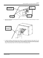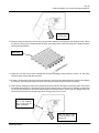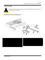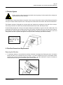
1
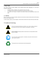
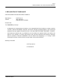
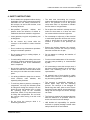
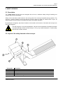
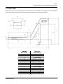
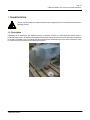
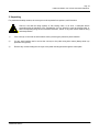
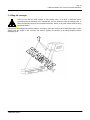
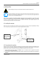
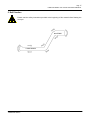
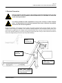
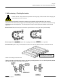
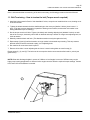
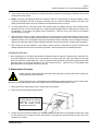
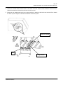
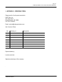
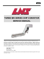
V1.0 TURBO MH SERIES CHIP CONVEYOR SERVICE MANUAL Thank you for choosing an LNS Chip Conveyor. We are proud to have you among our LNS family of users. LNS Chip Conveyors simply and reliably remove waste from machining operations. Machine efficiency is increased and operator safety is improved since the conveyor works with little operator attention and without interrupting production time. LNS Conveyors are available for many types of machine tools or other applications. They can be arranged to deliver wet or dry waste to containers or to conveyor or chute-type disposal systems. For further information, contact: Inside Sales Department LNS TURBO 203 Turbo Drive Kings Mountains, NC 28086 This Service Manual is intended to assist with the normal maintenance that will assure long service life of your LNS Chip Conveyor. Page 2 TURBO MH SERIES CHIP CONVEYOR SERVICE MANUAL TABLE OF CONTENTS CHAPTER 1 BASIC NOTIONS 1. STRUCTURE 2. RIGHTS 3. DECLARATION OF COMPLIANCE 4. SAFETY INSTRUCTIONS 5. SAFETY DEVICES 6. FLOOR PLAN 7. LAYOUT OF THE ELEMENTS 4 5 6 7 8 9 10 CHAPTER 2 SETTING INTO OPERATION 1. TRANSPORTATION 2. UNPACKING 3. LIFTING 4. INSTALLATION 5. BELT DIRECTION 13 14 15 16 17 CHAPTER 4 ELECTRICS 1. ELECTRICAL CONNECTION 2. ELECTRICAL CONTROL 179 20 CHAPTER 5 CONVEYOR BELT 1. BELT TENSION 2. BELT REMOVAL / INSTALLATION 3. BELT ASSEMBLY 21 23 28 CHAPTER 6 FILTRATION 1. FILTRATION SYSTEM 2. FILTER BOX INSTALLATION & REMOVAL 3. FILTER CLEANING BRUSH REPLACEMENT 30 30 31 CHAPTER 7 MALFUNCTIONS 1. TROUBLE SHOOTING 2. FACTORS AFFECTING PERFORMANCE 3. MAINTAINANCE 4. CLEAINING 34 35 35 35 CHAPTER 8 APENDICES 1. ORDERING FORM 2. LNS ADRESSES TURBO MH Series 37 37 Page 3 TURBO MH SERIES CHIP CONVEYOR SERVICE MANUAL BASIC NOTIONS TURBO MH Series Page 4 TURBO MH SERIES CHIP CONVEYOR SERVICE MANUAL 1. STRUCTURE This manual consists of various chapters, each containing several points, paragraphs, etc. Lists may be contained in paragraphs. The page number is indicated in the top right-hand corner of the page. The chapter number and title are indicated in the top left-hand corner of the page. The model of the Conveyor is indicated in the bottom left-hand and top right-hand corners of the page. 1.1. Captions Whenever possible, the reference numbers contained in the instruction manual are shown with the LNS ordering number of the indicated element. To make it easier to place an order of supplies, a form has been included in the annex at the end of this manual. 1.2. Symbols and terminology This sign recommends following the directions very closely avoiding causing an incident that could result in injury, damage to the equipment, or data loss. This sign indicates that safety measures must be taken to avoid possible electrical shocks or mishaps. The notes stress interesting points or comments, and provide useful advice for optimal system operation. This sign points out an advice about environmental protection. TURBO MH Series Page 5 TURBO MH SERIES CHIP CONVEYOR SERVICE MANUAL 2. RIGHTS All rights reserved. Reproduction, recording or transmission of all, or any portion, of this manual, in any form or through any means whatsoever, whether mechanical, photographic, sound or other, without the express written authorization of LNS SA, is prohibited. LNS SA disclaims all responsibility for errors which may be contained in this manual and the problems which may result therefore. LNS SA and its subsidiaries cannot be made responsible for the debts, losses, expenses, or damage incurred, or suffered, by the buyer of this product, or a third party, following an accident, incorrect use, or misuse, or stemming from modifications, repairs, or transformations not authorized by LNS SA. LNS SA and its subsidiaries cannot be held responsible for damage and problems arising from the use of options and products other than LNS products, or products approved by LNS SA. The names of the products indicated in this manual are registered trademarks TURBO MH Series Page 6 TURBO MH SERIES CHIP CONVEYOR SERVICE MANUAL 3. DECLARATION OF COMPLIANCE NOT APPLICABLE FOR NON CE US BUILT MODELS Manufacturer Address : : LNS Turbo, Inc. 203 Turbo Drive Kings Mountain, NC 28086 Declares that: The Turbo HB chip conveyor - Is designed to be incorporated into a machine, or to be assembled with other machines, to create a machine covered by Directive 89/392/EEC amended, and that the following (parts/paragraphs) of the harmonized standards have been applied: EN 292, EN 60 204 1, EN 1088, EN 418, EN 60947, 89/336/EEC, 73/23/EEC. - And furthermore declares that it is prohibited to put the machine into operation before the machine into which it is to be inserted, or of which it will become a part, has been examined and declared in conformity with the provisions of Directive 89/392/EEC and the national laws transposing it, i.e. forming a whole including the machine to which reference is being made in the present declaration. Barnsley, 23.08.2005 LNS Turbo UK Ltd N. Duckmanton TURBO MH Series Page 7 TURBO MH SERIES CHIP CONVEYOR SERVICE MANUAL 4. SAFETY INSTRUCTIONS Do not handle the equipment without having knowledge of the safety instructions and the instructions for use. Safety instructions for the conveyor, as well as the machine, must be strictly observed. The work area surrounding the conveyor system should always be clear of objects and well lit. The presence of oil on the ground could cause falls; it is important to maintain the floor clean on a regular basis. Non-qualified personnel, children, and persons under the influence of alcohol or medication should not handle the equipment. Do not place the machine in a damp area and make sure that water or oil does not come into contact with the electrical equipment. Loose garments, long hair and jewellery can be dangerous. Do not remove any covers while the conveyor or the machine is under electrical power. Do not attempt to adjust any of the electrical or mechanical protection devices such as the clutch or shock relay as severe damage to machine or persons in the proximity can occur. Do not conduct any maintenance operations during the automatic operation. Ensure the interface between the conveyor and machine prevents the conveyor running when the machine door is open Do not grasp moving or rotating objects, or nearby elements. Do not attempt to recharge the batteries of any PLC uses. If certain safety shields or safety covers are removed to conduct maintenance, they must be reinstalled as soon as the maintenance work is completed. For the use and maintenance of the conveyor, use only parts provided by or recommended by LNS. No servicing should be carried out on the interface or inside the electrical cabinet while the conveyor or the lathe are under electrical power. It is strictly prohibited to jump wire or remove circuit breakers, main switches, and especially safety switches. To avoid any harm to persons, or damage to components, use only the indicated points for lifting and moving the conveyor. No one should be near the hanging load, or within the operating range of the overhead hoist/crane, forklift, or any other means used for lifting and transportation. Do not knock the conveyor while moving it as this could damage it. Do not move the conveyor while it is electrically powered on. TURBO MH Series If it is necessary to move the conveyor once it has been originally installed, do not reinstall it before first contacting LNS or its local representative. No exposed area of belt should be visible outside of the conveyor or machine guards at any time during operation. The conveyor is specifically designed to handle waste chips from the machining process. The conveyor is not designed to handle large bar ends, parts or tools. Ensure that these foreign objects are prevented from falling into the conveyor as serious damage can result. The Conveyor must be left running at all times while the machine is in operation. Failure to do this can result in serious damage. LNS disclaim all responsibility for possible accidents or property damage caused when safety instructions are not followed. Page 8 TURBO MH SERIES CHIP CONVEYOR SERVICE MANUAL 5. SAFETY DEVICES 5.1. Description The TURBO MH500 conveyor has been designed with a focus on maximum safety during its handling and complies with all EC requirements. Safety covers and devices make access to the moving parts of the conveyor impossible during operation. The conveyor – machine interface must ensure that the conveyor cannot run when the machine door is open. All safety interlocks on the conveyor or machine must not be over written at anytime. By pressing the emergency stop button located on the machine, the functions of the lathe and conveyor are immediately stopped. The LNS company, or its local representative, may not be held responsible for possible accidents or property damage, whether caused directly or not, by any means whatsoever, if certain safety devices have not been included. 5.2. Layout of the safety elements on the conveyor 1 2 3 5 4 Designation 1 2 3 4 5 TURBO MH Series Description Drive cover Top cover incline Top cover load Bearing cover End Cover discharge Page 9 TURBO MH SERIES CHIP CONVEYOR SERVICE MANUAL 6. FLOOR PLANS Each conveyor varies in size depending on the machine tool it is designed to fit to. Below is a general diagram which can be used to help in communications with LNS regarding size queries and enquiries’ A B D SECTION A - A C E F L K A M G A J H I Drawing Dimension A B C D E F G H I J K L M TURBO MH Series Conveyor Terminology Baffle width Baffle height LH Frame width Baffle height RH Baffle length Top cover load Tail height Load length Conveyor length Load above floor Discharge height Overall height Incline angle Page 10 TURBO MH SERIES CHIP CONVEYOR SERVICE MANUAL 7. Layout of the elements 8 3 7 2 6 1 5 4 9 39 10 38 5 36 35 34 11 33 12 13 14 32 37 21 15 22 28 31 20 19 23 27 26 16 24 17 30 25 29 TURBO MH Series 18 Page 11 TURBO MH SERIES CHIP CONVEYOR SERVICE MANUAL 7. Layout of the elements cont.d Designation 1 2 3 4 5 6 7 8 9 10 11 12 13 14 15 16 17 18 19 20 21 22 23 24 25 26 27 28 29 30 31 32 33 34 35 36 37 38 39 Description End cover discharge End plate discharge Top cover discharge Side plate discharge RH Bearing Torque angle (motor mounting plate) Motor Drive cover Access cover discharge - RH Top cover incline Incline track - RH Incline track - LH Baffle LH Baffle RH Tail baffle Tail disc Tail end cover Filter box blanking plate Load track - RH Load track - LH Lower curve track RH Lower curve track LH Formed load Filter box gasket Filter box Bottom cover lower curve Formed incline Leg brace Castor Castor plate Leg extension Formed leg Side plate discharge LH Access cover discharge - LH Belt guide disc Drive sprockets Bearing cover Drive shaft Bearing mounting bracket Please note that the appearance of the conveyor may vary and some components may not be present on your conveyor due to application design TURBO MH Series Page 12 TURBO MH SERIES CHIP CONVEYOR SERVICE MANUAL SETTING INTO OPERATION TURBO MH Series Page 13 TURBO MH SERIES CHIP CONVEYOR SERVICE MANUAL 1. TRANSPORTATION Please read the safety precautions described at the beginning of this manual before handling the following devices. 1.1. Description Depending on its destination, the MH500 conveyor in normally secured to a pallet then heat sealed inside a protective plastic cover. All shipping documents including this manual are also secured to the pallet. Regardless of the type of packaging, the un-creating and lifting instructions recommended by LNS must be observed in order to prevent any injuries to persons and damages to objects. TURBO MH Series Page 14 TURBO MH SERIES CHIP CONVEYOR SERVICE MANUAL 2. Unpacking For practical and safety reasons, the conveyor must be unpacked in a spacious, well-lit location. Check to see that the lifting capacity of the hoisting crane, or lift truck, is adequate before proceeding with the handling of the merchandise. No one should be near the hanging load, or within the operating range of the overhead hoist/crane, forklift, or any other means used for lifting and transportation. 1) If the conveyor is received as shown above start by removing the protective plastic material 2) Cut any steel banding used to secure the conveyor to the pallet using side cutters (always wear eye protection and gloves) 3) Remove any screws holding the conveyor to the pallet including those through the castor plate. TURBO MH Series Page 15 TURBO MH SERIES CHIP CONVEYOR SERVICE MANUAL 3. Lifting the conveyor Check to see that the lifting capacity of the hoisting crane, or lift truck, is adequate before proceeding with the handling of the merchandise. No one should be near the hanging load, or within the operating range of the overhead hoist/crane, forklift, or any other means used for lifting and transportation. Lifting points are strategically placed around the conveyor to allow the conveyor to be safely lifted with a crane. Always read the weight on the conveyor and check it against the capacity of the lifting equipment before attempting to lift: TURBO MH Series Page 16 TURBO MH SERIES CHIP CONVEYOR SERVICE MANUAL 4. INSTALLATION Before installing the conveyor, ensure that the machine is stable and power is off. During the installation of the conveyor ensure that all ship loose parts are fitted to the conveyor as failure to do so will result in inefficient operation. For a list of ship loose parts supplied with the conveyor refer to the shipping packing list.. Each conveyor is supplied with detailed installation instructions that apply specifically to the design of that conveyor. As machines vary in size and dimension, installations vary from machine to machine. For specific conveyor to machine installation instructions see the “installation instructions” sheet supplied separate to this manual and the general details in the sections below. 4.1 Levelling the conveyor When the conveyor is installed to the machine it may be necessary to level the conveyor by adjusting the setting of the conveyor leg in conjunction with a level. See the diagram below for details. Loosen the 4 bolts and tighten them once the leg is set. Raise / lower the leg until the conveyor is level. 4.2. Connection to the machine Once the conveyor has been installed to the machine, the conveyor must be connected to the interface of the machine and if an Air header is supplied an air supply must be connected to the conveyor. At this stage all guards must be in place as indicated in the specific installation instructions and in this manual. • • For the electrical connection, please see chapter 3 and, if an electrical control is supplied, the electrical drawing in the conveyors electrical box. If an Air header is supplied the pneumatic (airline) must be connected to the Air header inlet as indicated in chapter 6. TURBO MH Series Page 17 TURBO MH SERIES CHIP CONVEYOR SERVICE MANUAL 5. Belt Direction Please read the safety instructions provided at the beginning of this manual before Starting the conveyor DISCHARGE TURBO MH500 TURBO MH Series Page 18 TURBO MH SERIES CHIP CONVEYOR SERVICE MANUAL ELECTRICS TURBO MH Series Page 19 TURBO MH SERIES CHIP CONVEYOR SERVICE MANUAL 1. Electrical Connection Particular attention should be given to the handling of electrical elements because of risks of electrocution. In case of possible electrical malfunctions, it is advisable to contact LNS or their local representative. It is strictly prohibited to make adjustments as long as the conveyor is under electrical power. The adjustments of the electrical equipment must only be performed by qualified personnel in line with local regulations. During the installation, ensure that the motor is wired in accordance with the supply voltage available. The supply voltage of the conveyor is indicated on the electrical drawing supplied in the conveyors control panel. If no control panel is supplied then the voltage can be checked directly at the conveyor motor terminal box as below. Even if the electrical drawing is correct to the machines requirements the conveyor motor should be checked to ensure the voltage setting is correct to prevent possible damage. Motor terminal box Control box Optional Cable from control box to motor Cable from control box to be connected to the machine TURBO MH Series Page 20 TURBO MH SERIES CHIP CONVEYOR SERVICE MANUAL 1.1 Setting the voltage of the motor If the voltage does not correspond, the wiring of the motor must be modified: 2. ELECTRICAL CONTROL Your conveyor may or may not be supplied with an electrical control depending on the machine’s and applications’ requirements. If an electrical control is supplied then please see the electrical drawing inside the control panel for specific details. If any faults with the conveyor control occur consult your local LNS agent. If a fault in the power supply to the conveyor is detected the control will automatically cut the power to the conveyor motor. If this should occur please see the section below: 2.1. Circuit breaker Circuit breakers interrupt the 3 phases, which power the Conveyor. If the conveyor requires excessive power, the breaker activates and push-button (C) STOP is released. safety reason, the power supply to the conveyor is immediately interrupted. After having located and repaired problem causing this interruption, reset the circuit breaker by the push-button (F) START. At the factory, the breaking current is set according to the conveyors design, this setting can be found on the conveyor drawing in the control panel Designation A circuit For B the pressing F C electrical Description A Power in connecting terminal B Setting the breaking current C Release button D Power out connecting terminal E Test push-button F Reset button TURBO MH Series E D CONVEYOR BELT Page 21 TURBO MH SERIES CHIP CONVEYOR SERVICE MANUAL 1. Belt tensioning – Checking the tension Please read the safety instructions provided at the beginning of this manual before carrying out any maintenance on the conveyor. Correct conveyor belt tension is essential to ensure proper operation and extended life of the conveyor components. The belt has been properly tensioned during factory assembly. As normal wear occurs the belt may become slack and need adjustment. The following factors may be used to determine whether the belt needs adjustment. Belt too loose: Belt slack at exit point of the drive sprocket before re-entry into frame (see illustration). Belt too tight: Belt has intermittent jerks and a popping sound while the conveyor is in operation. Uneven tension (side to side): The belt tends to track to one side. An indication of this is excessive wear on Excessive wear will be seen on the edge of the side wing. outside of side wings as shown below: Check to see that the clutch body is square to the bearing mounting bracket. If it is not, this will generally indicate which direction the belt is off on side to side tension. TURBO MH Series Page 22 TURBO MH SERIES CHIP CONVEYOR SERVICE MANUAL Once it is determined that re-tensioning of the belt is necessary, the following procedure should be followed: 1.1. Belt Tensioning – How to tension the belt (Torque wrench required) 1. Install the belt as stated in Section “belt installation” below, except do not install the drive cover, bearing cover or tension the belt. 2. Tighten the bolts that attach the drive shaft bearings to the conveyor (labelled 1 below), then loosen 1 ¼ turns. (This step ensures that bearing is parallel to bearing mount surface, and that the lock washer is not adding additional torque to reading.) 3. Set the torque wrench to 2.8Nm. Tighten (clockwise) each bearing adjusting bolt (labelled 2 below) on each side of the conveyor, alternately until 2.8Nm is obtained and torque wrench no longer turns adjusting belt, but clicks at rotation. 4. Manually rotate belt back and forth. (This distributes tension evenly throughout the belt). 5. Repeat steps (3) and (4) until belt rotation no longer results in decreased torque setting. This step ensures that both sides of belt are tensioned equally.) Lock adjusting bolts. 6. Run machine for a two-hour break-in period. 7. Remove drive chain. Loosen adjusting belt lock nuts. Loosen bearing belts as noted in step (2). Repeat steps (3), (4), and (5). The belt must be re-torqued to obtain correct tension after break-in period (see guide below). NOTE: Belts with discharge heights in excess of 1200mm or load lengths in excess of 2500mm may require higher torque settings application or different incline angles can also affect the required torques settings. Contact LNS Turbo UK Ltd if assistance is needed. 1 2 TURBO MH Series Page 23 TURBO MH SERIES CHIP CONVEYOR SERVICE MANUAL Torque Guide • Overall Length to 5700 mm 2.8 Nm • Overall Length 5700 to 9500 mm 4.0 Nm • Overall Length 9500 mm and over 5.1 Nm 2. Belt Removal and Installation Please read the safety instructions provided at the beginning of this manual before carrying out any maintenance on the conveyor. 1. Remove the motor and bearing cover from the discharge. 2. One by one loosen and remove the 2 bolts holding the motor to the motor mounting plate (Torque arm). When removed the motor can be slid off the drive shaft and removed (note: keep hold of the key used in the keyway as this will be required for re-assembly) When the nuts and bolts are removed slide the motor off the drive shaft. Remove the 2 bolts holding the motor to the motor mounting plate. 3. Loosen the lock nuts on the belt tension adjusting screws (see drawing below) and back off the belt tensioning adjusting screws (see drawing below) until they are flush with the face of the adjusting bracket. 4. Loosen the two bolts holding each pillow block bearing. 5. Slide the drive shaft toward the tail of the conveyor as far as the adjusting slots for the pillow block bearings will allow. This will provide maximum slack in the belt. TURBO MH Series Page 24 TURBO MH SERIES CHIP CONVEYOR SERVICE MANUAL Belt tensioning adjusting screws Locking nut Pillow Block bearing mounting bolts Pillow Block bearing 6. Remove the maintenance access panels from each side of the conveyor side plate discharge’s to expose either side of the belt. Remove access panels at each side of the conveyor 7. It may be necessary to rotate the belt until a cotter pin is in position through the access panel. This can normally be done by hand (using hand tools) or it may be necessary to temporarily reconnect the motor for this. When the cotter pin in in position as shown below carefully remove it from the end of the pin (before doing so ensure that you have a new one to replace it when re-installing the belt). TURBO MH Series Page 25 TURBO MH SERIES CHIP CONVEYOR SERVICE MANUAL Carefully remove the cotter pin from the end of the belt pin 8. Being careful to catch the flat washers and rollers, pull the hinge pin out through the access panel on the opposite side of the conveyor as shown below. Extract the belt Pin like this 9. Grasp the end of belt below the drive shaft and pull the belt out of the conveyor. Be sure to wear gloves to avoid being cut by sharp edges on the belt. When only a few feet of belt remain in the conveyor, the belt on the floor will have enough weight to begin pulling the remainder out on it's own. As the last of the belt begins to run out faster, don't attempt to stop it; just stand clear and let it run out onto the floor. Note that the belt was moved in the direction opposite normal belt travel. TURBO MH Series Page 26 TURBO MH SERIES CHIP CONVEYOR SERVICE MANUAL Remove the belt this way 10. Before moving the old belt out of the way, pay particular attention to the way the side wings overlap. When the belt is running in the normal direction of travel, the leading ends of the side wings are outboard, and the trailing ends are inboard Side wings 11. Place the new belt on the floor beneath the conveyor discharge, being careful to orient it in the same direction as the old one that was removed. 12. If there is not already a hinge pin in the end of the belt, use the pin and rollers that were removed to separate the old belt. There must be a pin and rollers in the extreme end of the belt for ease of insertion. 13. With a person standing on either side of the belt, lift up the lead end and start it in the lower track, from which the old belt was pulled out. Be sure and wear gloves to prevent injury, and be sure to maintain a secure hold on the belt until at least five feet have been fed into the conveyor frame. At this point, the weight of the belt inside the frame should be enough to prevent it running back out on it's own. Rollers and pin must be in the extreme end of the belt for ease of insertion Insert the belt in the reverse direction from taking it out TURBO MH Series Page 27 TURBO MH SERIES CHIP CONVEYOR SERVICE MANUAL 14. Continue feeding the belt into the conveyor frame. One person may have to use a pry bar to "help" it along from time to time. Force should not be required. Many times the belt can be pushed in all the way around from the discharge end. If the belt hangs up, look for some obstruction; don't force it. 15. When the lead end of the belt reaches the drive shaft, carefully feed it up over the drive sprockets. 16. Remove the hinge pin and rollers that were used to help guide the belt through the track. 17. With the ends of the belt engaged in the teeth around the top and bottom of the drive sprockets, the two ends should join. At this point, it may be necessary to remove one or more hinge plates from the new belt. Most new belts are supplied longer than necessary. 18. Reverse steps 1 through 7. When carrying out step 2 in reverse ensure that the motor is not raised too high as to cause unnecessary stress on the chain. The chains should be tight but there should move together around 5mm when squeezed. Also ensure that all lock nuts are secured before testing. 19. When adjusting belt tension, clamp a pair of vise grip pliers on one of the formed cleats on the belt. Use the vise grips to "rock" the belt back and forth to feel the slack and drag on the belt. There should not be more than enough slack to allow rocking the drive shaft through 15 degrees of rotation without moving the belt. On a new belt, zero slack is O.K., but if the belt is difficult to move with the vise grips, it's too tight. 20. Visually confirm the belt is located in the center of the frame. Adjust if necessary by loosening the setscrews in the pillow block bearings and shifting the drive shaft; motor and all; to the left or right as appropriate. 21. Re-connect power and test run the conveyor. The belt should run freely and the only sound should be a subdued clicking as each hinge plate passes over the drive sprocket. TURBO MH Series Page 28 TURBO MH SERIES CHIP CONVEYOR SERVICE MANUAL 3. Belt Assembly Please read the safety instructions provided at the beginning of this manual before carrying out any maintenance on the conveyor. Belt with internal filter cleaning brushes 7 1 1 8 5 1 6 2 9 3 1 0 4 ITEM NO. PART NAME 1 Hex head screw Lock washer Tail disc (on inside of frame) 2 Drilled hinge plate for brush attachment 3 M5 Screw with lock washer 4 Bolt on filter box brush 5 Belt link pin TURBO MH Series ITEM NO. 6 7 8 9 10 11 PART NAME Washer Roller Side wing - Left Side wing - Right Cotter pin Hinge plate with welded cleat Page 29 TURBO MH SERIES CHIP CONVEYOR SERVICE MANUAL FILTRATION TURBO MH Series Page 30 TURBO MH SERIES CHIP CONVEYOR SERVICE MANUAL 1. Filtration System Please read the safety instructions provided at the beginning of this manual before carrying out any maintenance on the conveyor. The MH500 also incorporates filtration in the side of the conveyor body which cleans coolant flowing through the conveyor to 500µm maximum particle size. This keeps the coolant tank much cleaner and reduces maintenance. The filtration consists of a flanged box or boxes which are inserted into an aperture in the side of the conveyor. The base(s) of the box is made from perforated stainless steel sheet metal, with 500µm holes. Coolant flowing through the conveyor must pass through the perforations to get out into the coolant tank. The perforations in the filter box are cleaned every minute by a series of brushes which are connected to the inside of the hinge belt. These brushes are normally not visible during the conveyors operation but access to view and change these brushes is possible through the access panel at the discharge (see below for details) To view the brushes the access panels at either side of the conveyor can be removed. 2. Filter Box Removal and Replacement Removing the filter box: 1. To determine whether or not the filter box surface is blocked or damaged, the filtering box (Item 3 as shown below) will have to be removed from the conveyor. On some machines this may be accessible without removing the conveyor from the coolant tank of the machine. On other machines it may be necessary to remove the entire conveyor from the tank to gain access to the box. TURBO MH Series Page 31 TURBO MH SERIES CHIP CONVEYOR SERVICE MANUAL 2. There may be more than one filter box. Each box should be examined for blockage or damage of the screen material that acts as a filter. 3. NOTE: Take care in handling the filter box so that the surface is not punctured, nor the box dropped. This is a precision fabricated unit and for proper functioning, the box must be handled carefully. Any rips in the filtering material will result in the loss of filtration and effectiveness of the conveyor. 4. To remove the filter box, remove the seven nuts, washers and lock washers (Items 4, 5 and 6 shown above. Slide the filter box out from the flanged side. Inspect the flange gasket (Item 2 shown above) to ensure it is not damaged. If so replace the gasket before re-assembly. Failure to do so can result in poor filtration efficiency of the conveyor. 5. After removal of the box, if there is a large build up of fine material is on the bottom surface of the box (the filtering surface), it would indicate that the material is not being removed via the self-cleaning brushes (some material in the box is to be expected during normal operation) if flow is affected or there is a large build up of chips on the mesh then these brushes should be replaced (see the section below “replacement of brushes”). 6. After removal of all loose material on the surface, inspect the box to determine if any fine elements have wedged themselves in the holes in the filtering element. Remove these prior to reinstalling the box. Installing the filter box: 1. After cleaning the box or replacing the brushes as described above, make sure that the area in which the box is mounted inside the conveyor is free of any debris and chips as the box must seat inside the conveyor frame and must form a water-tight joint. Epoxy or gasket cement should be used with the gasket and the box tightened down in a three-step process so as not to distort the frame. Take care not to over-tighten bolts, light compression of the gasket is all that is required. 3. Replacement of brushes Please read the safety instructions provided at the beginning of this manual before carrying out any maintenance on the conveyor. If the brushes are worn or damaged then the following procedure should be used to replace them, Note there are several brushes used on the conveyor belt so each should be looked at in turn: 1. Remove the drive and bearing covers to expose the access panels. 2. Remove the access panels as shown below. Remove the access panels at either side of the conveyor discharge. To do this the drive and bearing covers must also be removed. 3. Position the belt so that the brushes are visible through the access panel in the position shown below (note the belt will need to be rotated to access each brush in turn) great care should be taken to stay clear of the belt when it is rotating. TURBO MH Series Page 32 TURBO MH SERIES CHIP CONVEYOR SERVICE MANUAL 4. There are 4 screws which hold the brush to the inside of the belt. These screws should be removed in turn. When the screws are removed the old brush can be removed. 5. Mount the new replacement brush in the same position as where the old brush was removed from. Attach the brush in place using the 4 Screws that held the old brush in place. Filter box brush Belt Fixing screws TURBO MH Series Page 33 TURBO MH SERIES CHIP CONVEYOR SERVICE MANUAL MALFUNCTIONS TURBO MH Series Page 34 TURBO MH SERIES CHIP CONVEYOR SERVICE MANUAL 1. TROUBLE SHOOTING GUIDE The following chart will show some problems and their probable causes with solutions. PROBLEM POSSIBLE CAUSE POSSIBLE SOLUTION Conveyor stalls shock relay trips (1) Chip jam If the conveyor belt jams due to an excessive build up of chips within a section of belt then the conveyor belt should be reversed, using the control, momentarily then run forward. This is normally enough to clear the jamb. If this is unsuccessful after a number of attempts consult your LNS agent. (2) Incorrect belt tension Refer to belt tensioning section. (3) Tail discs Check for loose or missing screws. (4) Side wings bent or missing Repair or replace. (5) Cotter pin missing from link pin Replace cotter pin. (6) Shock relay setting Refer to electrical drawing provided or contact your local LNS agent. (7) Sludge and/or chips inside frame Remove belt and clean. Belt flutters Incorrect belt tension Refer to belt tensioning section. Excessive wear on outside of side wings (1) Belt misalignment Look for sideward motion of belt caused by loose sprockets. If necessary, open belt, align sprockets and retighten set screw. (2) Uneven side to side tension Refer to belt tensioning section. (3) Incorrect levelling Check levelling of frame to ensure it is not twisted. If necessary, adjust levelling screws located in foot until conveyor has correct levelling. (4) Chip jam inside frame Remove belt and clean frame. (1) Damaged or worn filter box assembly Replace the filter box (see filter box removal / replacement section above). (2) Improper seal of filter box Remove and replace gasket. (1) Blocked filter box assembly Remove and clean / replace the filter box (see filtration chapter above) (2) Damaged / worn filter cleaning brushes. Replace the filter cleaning brushes from the inside of the conveyor belt (see the filtration chapter above) (1) Loose electrical connection Check connections and tighten. (3) Sludge/Chip build-up inside frame Remove belt and clean. Deteriorating fines removal efficiency Low coolant flow through boxes or conveyor over flow Motor overloads/kicks out excessively TURBO MH Series Page 35 TURBO MH SERIES CHIP CONVEYOR SERVICE MANUAL 2. FACTORS AFFECTING PERFORMANCE 2.1. Installation The installation is a very important phase that, if neglected, could seriously impede the operation and efficiency of the conveyor system. Level The conveyor must be properly levelled otherwise the flow of coolant through the conveyor will prevent efficient running such as poor coolant drainage, leakage to the floor or surrounding area, wetter than normal chips and poor interfacing of the conveyor baffles and / or flange to the machine Alignment If the conveyor is not aligned to the machine and / or tank then the conveyor baffles will not mate to the tank and / or casting properly which will result in an increased volume of chips into the machine tank. The incorrect alignment of the conveyor to the machine and / or tank can also result in safety issues as areas of exposed belt may be seen. Conveyor running It is important to continually run the conveyor while the machine is running. Stopping the conveyor will prevent the self cleaning filtration system from working and will result in low coolant flow or conveyor flooding. Loose parts In some cases the conveyor may be supplied with additional bolt on or loose parts that are designed to improve the conveyors performance with the particular machine. This can include adjustable conveyor baffles, flanges and levelling feet. If these are not installed the conveyor may not perform efficiently on the machine. 3. MA INT EN AN CE Plea se read the safe ty instr uctions provided at the beginning of this manual before handling the following devices. At no time should solvents, such as acetone, or diluents be used for cleaning the Conveyor. At no time should cleaning products come into contact with electrical components. After first 100 hours of operation and at regularly scheduled intervals to suit operating conditions: • Replace the filter box cleaning brushes every 3000 hours. • Check coolant flow is constant through the filter boxes (for blocked filter screens). • Inspect conveyor belt parts for excessive wear. If excessive wear is noted, belt should be removed and repaired. (Refer to chapter 5 for belt removal instructions.) • Grease pillow block bearings, using grease gun. Do not grease too often – bearing seals could be damaged. • Check belt tension. 4. CLEANING For cleaning the conveyor, use a soft cloth and a regular detergent. The use of compressed air for cleaning is not advisable, because particles could become lodged in sensitive areas of the conveyor and impede proper operation.. TURBO MH Series Page 36 TURBO MH SERIES CHIP CONVEYOR SERVICE MANUAL APENDICES TURBO MH Series Page 37 TURBO MH SERIES CHIP CONVEYOR SERVICE MANUAL 1. APPENDIX C: ORDERING FORM Please email or fax the parts required to: LNS Turbo, Inc. 203 Turbo Drive Kings Mountain, NC 28086 Fax: 704-739-6039 Email: [email protected] Attn: Service & Parts Qty. Ordering no. Description Expected delivery: Location and date: Signature and stamp of the company: . TURBO MH Series