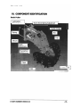
1
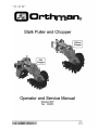
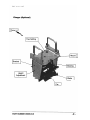
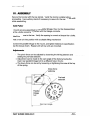
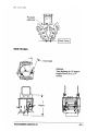
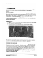
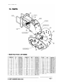
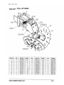
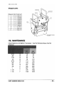
www.orthman.com
STALK
PULLER
OPERATOR’S MANUAL
ORTHMAN
MANUFACTURING
INCORPORATED
STILL THE STRONGEST
ORTHMAN MFG. INC.
75765 RD. 435
LEXINGTON, NE 68850
OM09-03-01
WARRANTY
Orthman Mfg., Inc. warrants the whole goods products it manufactures to be free from defects in material or workmanship for a period of
one (1) year from the date of sale of the product(s) to the original user. Products not manufactured, but supplied by Orthman Mfg., Inc. on
Orthman products, are subject to, conform with, and are limited to the warranty of our suppliers.
Orthman Mfg., Inc. warrants the parts it manufactures to be free from defects in material or workmanship for a period of ninety (90) days
from the date of delivery of the product(s) to the original user. Products not manufactured, but supplied by Orthman Mfg., Inc. on Orthman
products, are subject to, conform with, and are limited to the warranty of our suppliers.
Warranty of Orthman whole goods and/or parts applies only to material and workmanship. Misuse, misapplication, neglect, alteration,
accident, normal wear, or acts of God affecting Orthman products are not eligible for warranty.
Warranty of serial numbered goods will only be considered if the product has a completed Warranty Registration on file at Orthman. This
Warranty Registration must be completed and returned to Orthman within thirty (30) days of the sale of the product(s) to the original user.
No serial numbered goods or related parts and/or labor will be warranted without a Warranty Registration on file. Warranty
issues falling within the first thirty days of a product’s use will be handled at the discretion of Orthman. Warranty of parts will not require a
Warranty Registration, but proof of date of delivery of the product to the original customer must be provided.
WARRANTY CLAIMS: A warranty claim and request to return defective product(s) must be presented to the Orthman Service
Department by the selling dealer describing the defect in material or workmanship of an Orthman product(s) within ten (10) days of its
discovery. This claim may be made via phone, e-mail, fax, or written request. Claims for warranty of serial numbered goods must include the
Orthman product serial number and model number. Claims for warranty of parts will not require a product serial number or model number,
but must be identified by an Orthman part number. Claims for warranty of whole goods or parts must also include proof of date of sale of the
product to the original customer by an Orthman dealer.
The Orthman Service Department will proceed in making a preliminary decision as to the eligibility of the claim for warranty consideration.
After the Orthman Service Department deems it necessary to proceed with warranty consideration, a Return Goods Authorization (RGA)
will be completed by the Orthman Service Department in conjunction with the selling dealer. Upon completion of the RGA, the defective
product(s) must be returned to Orthman to ensure warranty consideration. Defective product(s) must be returned to Orthman by either the
selling dealer or the customer. Customer delivery of defective product(s) must be approved by Orthman and the selling dealer prior to delivery.
The defective product(s) in question must be sent, freight prepaid, within sixty (60) days of the discovery of the product(s) failure and initial
warranty claim. Replacement product(s) may be sent to the selling dealer, directly to the customer, or picked up at the Orthman facility.
Replacement product(s), sent directly to the customer or picked up must be approved by Orthman and the selling dealer. At the discretion
of the Orthman Service Department, replacement product(s) may be sent prior to, or after, the Orthman Service Department receives the
defective product(s).
Any variation in the above procedure is at the sole discretion of the Orthman Service Department.
No products will be accepted at Orthman without all proper paperwork completed including Warranty Registration and RGA(s).
Parts returned to Orthman without proper authorization will be returned to the sender at the sender’s expense.
Orthman agrees to handle all warranty claims in a timely manner and will inform dealers of any revisions or modifications to the Orthman
Warranty Policy. Eligible warranty claims will be processed by Orthman within sixty (60) days of receiving failed product(s) or a valid service
or repair labor claim. Eligible warranty claims regarding returned product(s) or service and/or repair labor will be paid through a credit memo
issued to the appropriate dealer’s account as determined by the Orthman Service Department.
If a warranty claim is found to be ineligible for warranty coverage, the Orthman Service Department will be responsible to inform the dealer in
order to determine the course of action to be taken. Orthman reserves the right to make changes in specification and design without notice
and without incurring any obligations to owners of products previously sold.
© Copyright 2005
Orthman Manufacturing Inc.
Lexington, Nebraska
All rights reserved.
Orthman provides this manual without warranty of any kind, expressed or implied. This manual reflects the product at the time of publication. All information
within is based upon current information on the publication date. Orthman assumes no responsibility for damages incurred due to the use of the illustrations,
information, and specifications within this publication.
Stalk Puller and Chopper
Operator and Service Manual
Released 9/03
Rev : 9/26/03
PART NUMBER OM09-03-01
-
-I
I TABLE OF CONTENTS
I.
WARRANTY
II.
SAFETY
.................................................................................................3
........................................................................................................4
.............................................................. 8
Ill.
COMPONENT IDENTIFICATION
IV.
ASSEMBLY
V.
VI.
VII.
VIII.
............................................................................................10
............................................................................................... 12
PARTS .................................................................................................. 13
MAINTENANCE...................................................................................15
TROUBLESHOOTING ............................................................................ 17
OPERATION
OM1
Orthman Mfg Inc.
75765 Rd 435 - PO BOXB
Lexington, NE 68850
(308)324-4654
PART NUMBER OM09-03-01
-2-
! This symbol is used to call attention to instructions concerning personal
safety. Be sure to observe and follow these instructions. Failure to do so
increases the possibility of personal injury or death. Read manual carefully
before operating or servicing your Orthman equipment.
You are responsible for the safe operation of your equipment. Anyone operating
maintaining or working around the bar must be familiar with the procedures and
pertinent safety information contained in this manual. Be careful when operating
the bar to avoid injury.
! CAUTION! Equipment is to be operated by qualified personnel only. A full
understanding of the operation, maintenance, and safety requirements is
mandatory before use.
! WARNING! Stand clear of implement and always make sure there are no
persons near it when in operation, or while being folded or unfolded. No riders
on the implement. Always unfold the wings completely before unhitching it from
the tractor. Be sure the implement is on a level and firm surface when not in use
and cycle the hydraulic control lever to relieve pressure in cylinders and hoses.
! WARNING! Do not allow children to play on or around the equipment.
Serious injury or death can occur from falling on sharp hard objects, or from
being run-over. Amputation of curious fingers or limbs is a possibility.
! WARNING! Watch for obstructions when folding of the outer wings. Make
sure that no one is within the swing arc of the wing, when folding or unfolding.
Serious injury or death can occur from being struck or trapped by the wing.
! WARNING! Always use all provided bar-stands to support the bar for
parking or storage. Do not rely on bar-stands to protect persons working around
or under equipment.
! WARNING! DO NOT work on unit when it is not connected to a tractor as
uneven or unpredicted forces may cause bar to fall, causing personal injury or
death, and equipment damage. Unit must be connected to tractor and quick-tach
latches closed before any maintenance or servicing is done.
! WARNING! Use care when disconnecting from the tractor and be sure to
support it. Personal injury or death and equipment damage may occur if
unsupported, unhitched bar is exposed to external or uneven forces (wind, thrust,
etc.). Store on level, solid ground such as a concrete pad.
-
PART NUMBER OM09-03-04
-4-
! WARNING! Always make necessary safety preparations prior to transporting
the machine on public roads. This includes installing Slow Moving Vehicle (SMV)
emblem and use of adequate lights or safety warnings after dark.
! WARNING! Be careful when operating on hillsides. Tractor can tip sideways
if it strikes a hole, ditch, or other irregularity.
! WARNING! Do not fold or unfold toolbar while on a side-hill. Bar may tip
over and take tractor with it.
! WARNING! Watch for obstructions such as wires, tree limbs, etc. when
folding and unfolding equipment. Serious injury or death can result from contact
with electric lines. Use care when moving or operating this machine near electric
lines to avoid contact.
! WARNING! Escaping hydraulic oil under pressure can have sufficient force
to penetrate skin, causing serious personal injury or death. Before attaching or
disconnecting hydraulic lines, relieve pressure by using controls at tractor.
Before applying pressure, make sure all connections are tight and lines, pipes,
and hoses are not damaged. Hydraulic oil escaping from a very small hole can
be almost invisible, and can amputate a limb or inject oil into the flesh. Use a
piece of cardboard or wood rather than hands to search for suspected leaks, or
take the bar to a qualified repair facility. If injured by escaping hydraulic oil, see a
doctor at once. Serious infection or reaction can develop if proper medical
treatment is not administered immediately.
! WARNING! Be extremely careful when working around unshielded discs,
sweeps, and coulter blades. Serious injury may result from contact with sharp
edges.
! WARNING! When working on the toolbar, block and use parking stand and
jack where necessary. Tractor should be turned off, in park, parking brake
engaged, and key removed from ignition.
! CAUTION! Be sure hydraulic cylinders and attaching hoses are fully
charged with oil before operating system. Air in system can cause fast
unexpected motion.
! CAUTION! The maximum transport speed for this bar is 20 mph (32 kph).
DO NOT EXCEED. Never travel at any speed that does not permit adequate
control of steering and stopping.
! CAUTION! Do not transport after dark without proper authority. Check all
lights and reflectors prior to transporting. All must be in working order and
visible.
PART NUMBER OM09-03-01
-5-
! CAUTION! Use care when transporting across rough ground. Excessive
speed diagonally across an uneven surface can cause loss of control, can upset
the bar, and can cause structural damage.
! CAUTION! Never lubricate or service machine while it is moving. Keep
away from power driven parts while running. Disengage all power before
performing maintenance.
! WARNING! Do not stand between tractor and implement unless the tractor
transmission is in park.
! CAUTION! Securely support any machine components that must be raised
for service work.
! CAUTION! Keep all parts in good condition and properly installed. Fix
damage immediately. Replace worn or broken parts. Remove any buildup of
grease, oil, or debris.
! WARNING! Before each use, inspect hitch pins for wear, stress cracks,
shear or bending deflection. Replace if wear exceeds 1I16" (diametral). Replace
only with high strength pins. The use of pins of lesser grade can result in failure,
loss of control, injury or death to operator and others, and damage to equipment.
! WARNING! Bar-stands must be used to secure and control the toolbar
before disconnecting from the tractor. Do not rely on row units to keep the bar
upright, as their ability to do so will depend on spring pre-load, and is not reliable
support. Failure to do so can result in injury or death.
! CAUTION! Disks are sharp. Amputation hazard. Do not place fingers,
hands, etc between disks while disks are moving. Do not spin disks while any
body parts are between them. Do not place hands on disk edges and spin as
fingers can be pulled into the contact zone and amputated. Do not lean on the
disks or the machine, as you can slip and since disks are free to rotate they can
collect incoming objects or fingers or limbs, entrain them to the pinch point, and
cut or amputate.
! CAUTION! Keep cleat fasteners tight. Loose cleats can be flung and cause
injury or structural damage.
! CAUTION! Do not attempt to hoist row unit into position on bar by hand.
Disks can rotate and cause amputation of limbs. Use a hoist.
PART NUMBER OM09-03-01
-6-
Safety Signs on Equipment
Safety signs should be kept legible.
Safety signs must be replaced if they are missing or illegible.
New equipment components installed during repair shall include the
current safety signs. Repair agent must see that repair includes
restoration of safety signs.
Safety signs may be ordered from the OM1 Parts department at the
location indicated below.
Safety signs are applied by preparing the surface. Remove all dirt and oil.
Clean and dry the area. Remove the backing. Align decal with the
components and lightly stick it on. Work the bubbles out with fingers or
plastic decal applicator. Apply firm pressure and push from center
outward until bubbles are removed and decal is firmly adhered. Persistent
bubbles can be removed by puncturing the decal and chasing the air out
through the hole with finger pressure.
Supplied signs, OM1 part numbers for ordering, and locations are as follows:
Description
Part
Number
Location
Direction it
faces
Warning, Thrown Objects
Warning, Tipping
Warning, Crushing Injury
153-146
153-403
153-529
Front of toolbar near hitch
Front of toolbar near hitch
Box of each outside row
unit
Front of toolbar near hitch
To the front
To the front
To the rear
Warning, Disks Have Sharp 153-045
Edges
PART NUMBER OM09-03-04
To the front
-7-
111. COMPONENT IDENTIFICATION
Stalk Puller
I Lubrication
I
I Disk ,I
PART NUMBER OM09-03-04
-8-
992-506.DQC
Chopper (Optional)
PART NUMBER OM09-03-01
-9-
IV. ASSEMBLY
Secure the tool-bar with the bar-stands. Verify the tool-bar is stable before
proceeding. Use auxiliary stands if necessary to assure that the bar will not shift
while assembling.
Stalk Puller
If mounts are pre-assembled to the parallel linkage, they must be disassembled,
as the u-bolts cannot be tightened with the linkage connected.
Install the mounts to the bar. Verify the spacing is correct and torque the u-bolts.
Hoist a row unit into position with a suitable lifting mechanism.
Connect the parallel linkage to the mount, and tighten fasteners to specification
(see the torque chart). Repeat until all row units are mounted.
Adjustments
The pinch force can be adjusted by loosening the left leg fasteners and
setting the pre-load setscrew.
Adjustment can be made to the cant angle of the disks by moving the
lower rear parallel linkage bolt to a different hole in the box.
The down-force can be set by loosening or tightening the screw at the top
of the spring.
DJsk Cant ~ n ~ l e
PART NUMBER OM09-03-04
-10-
p
- -.
Pre-load
setscrew
Stalk Chopper
Yaw Angle
Settings:
Yaw angles up to 15 degrees
Height from 19.5 to 21.5
inches
PART NUMBER OM09-03-01
Connect to the toolbar using the procedures defined in tractor andlor toolbar
manual.
Stow the bar-stands.
Move to the field and place the bar into the field position. Line up with the rows.
Select a gear. Field speeds in the range of 10 to 15 mph have been found to be
most effective. Proceed with operation. Stop and examine the results.
The photo below shows the cross-sections of stumps that were removed using
different height settings.
Viewed from L to R:
1. Stump that was cut out using a deep setting (high down-force, low toolbar)
2. Stump cut at the base of the stalk
3. Stump cut shallow (minimal down-force, andlor high bar setting).
The Operator may adjust the spring down-force, pinch force, and bar height to
tune into the mode that performs the best for his or her operation.
STOWING THE MACHINE
Keep personnel away from machine. Using the tractor, set the bar so row units
contact the ground and parallel linkages are level with the ground. Extend the
bar-stands before disconnecting from the tractor. Insert set-pins completely
through their holes to secure the legs in place. After all bar-stands have been
extended and secured with pins the machine may be detached from the tractor.
Do not stow with disks elevated as disks can still rotate, and pose a hazard of
crushing or amputation. Keep children away from the machine.
-
- -
-
-
PART NUMBER OM09-03-01
-
-12-
Stalk Puller Parts 24" DISKS
PART NUMBER OM09-03-01
Stalk Puller Parts- 28- DISKS
PART NUMBER OM09-03-01
-14-
Chopper parts
VII. MAINTENANCE
Check fasteners and tighten if necessary. Use the following torque chart for
reference:
PART NUMBER OM09-03-01
-15-
Lubrication
Lubricate the stalk puller parallel linkage with multi-purpose grease each day the
machine is in use.
Lubricate the chopper bearings each day the machine is in use.
The stalk puller hub bearings are sealed and do not require re-lubrication.
Examinationand Repair
Visual examination should be done each day of use.
Do not attempt to weld on the disks. The high carbon alloy is not repairable by
welding. Cracked disks must be replaced.
Check all components for cracks or damage. If components appear to be in
danger of coming apart, collapsing, or causing damage, repair or replace at
once.
Examine parallel linkage bushings for wear by pushing sideways on the box.
Excessive looseness may be cause for concern. Some disassembly is required
to examine bushings. Bushing replacement is necessary if wear and looseness
becomes excessive.
Use a hoist to lift the row unit or the tractor hitch to lift the bar, to permit rotation
of disks. Observe precautions about amputation. Carefully rotate disks and
listen for unusual sounds that might indicate bearing failure. Failed bearings
should be replaced.
The chopper bearings can be checked in a similar manner.
PART NUMBER OM09-03-01
-16-
Through normal use, a groove may
eventually wear into the lower disk. The life
of the disk can be extended with an
adjustment. If the groove becomes
approximately 1116" deep, it is
recommended that the relative disk positions
be reversed. For example, in the view at the
left, the right disk imposes on the left. These
can be reversed by lowering the right disk,
so that the left disk imposes upon it. Loosen
the left leg bolts, remove the right leg
fasteners and shift the right leg downward,
until the alternative set of holes is in
alignment. Fasteners must then be installed
in the alternative holes of the right leg.
Then reset the preload setscrew and tighten
the left leg fasteners.
Condition
Disks are plugging with debris
Stalks not being cut
Disks won't stay in the ground
Skips
PART NUMBER OM09-03-04
Comment
Speed too slow
Conditions too wet
Too much down pressure
Disk leg angle too aggressive
Failed hub bearing
Chopper blades dull
Chopper set too high
Speed too slow for chopper to
effectively cut stalks
Pinch force too small. Increase
pre-load at left leg set scew
Disk angle too vertical or upright
Not enough spring down-force
Disk pinch force too loose.
Check pinch force set screw,
locknut and leg fasteners
Hard, uneven soil conditions.
-17-
Parallel linkage not running level to the
ground
Excessive holes in ground where
stumps have been removed
Inconsistent or poor stalk removal
Unit may be bouncing. Adjust
springs for more down force
Hitch set incorrectly. Adjust
hitch height
Chopper height incorrect
Disks too deep into ground.
Disk cant angle too aggressive
Disks not deep enough
Chopper too deep into the
ground
Incorrect disk angle
Questions concerning the equipment, or the manuals should be directed to:
OM1
C/o Service Manager
Orthman Mfg Inc.
75765 Rd 435 - PO BOXB
Lexington, NE 68850
(308) 324-4654
PART NUMBER OM09-03-01
-18-