1
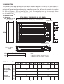
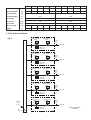
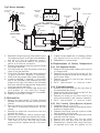
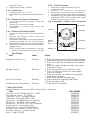
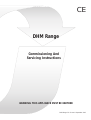
CE
DHM Range
Commissioning And
Servicing Instructions
WARNING: THIS APPLIANCE MUST BE EARTHED
DHM Range C & S Issue 6 September 2002
1. INTRODUCTION
The Powrmatic DHM range are multiple tube heating modules designed for insertion into duct heaters, air
conditioning plant and similar units. Each module comprises a number of gas fired forced draught burners
and a single exhaust gas fan venting into a closed flue system. Each burner/tube assembly in a module
is rated at 40 kW, 20kW, 15kW or 10kW output. DHM X/20 units are certified for use on Natural Gas, Group
H - G20 and Propane - G31 and are Cat II2H3P. (Note: Conversion from one gas to another is factory
completed.) DHM X/10, DHM X/15 and DHM X/40 units are certified for use only on Natural Gas, Group
H - G20 and are Cat I2H.
2. Technical Data
2.1 Dimensions
2740 DHM40, 2280 DHM15/20, 1630 DHM10
325 DHM10/15/20
650 DHM40
2300 DHM40, 1800 DHM15/20, 1160 DHM10
BURNER ASSEMBLY
See
below
REAR
FRONT
HEADER TUBES
GAS MANIFOLD
Gas connection size R1
BURNER END
EXHAUST FAN ASSEMBLY
DHM 5/xx MODULE
SHOWN
EXHAUST MANIFOLD
PLAN
Notes:
1 Low fire is with only one of the five burner modules running.
2 Maximum Ambient Temperature - 25°C
3 Maximum Gas Inlet Pressure - 60mbar
Module 3/xx 4/xx 5/xx 6/xx 7/xx
Height 910 1155 1400 1645 1890
2.2 Performance Data
3/10
4/10
5/10
6/10
7/10
3/15
4/15
5/15
6/15
7/15
Heat Input (Max)
kW
33.3
44.4
55.5
66.6
77.7
48.9
65.2
81.5
97.8
114.1
Heat Output (Max)
kW
30.0
40.0
50.0
60.0
70.0
45.0
60.0
75.0
90.0
105.0
Heat Input (Min)
kW
11.1
16.3
Heat Output (Min)
kW
10.0
15.0
Power Input
kW
0.11
0.11
Start Current
Amps
0.63
0.63
Run Current
Amps
m3/s
0.5
0.48
0.86
1.14
1.43
1.72
2.0
1.215
1.62
2.025
2.43
2.83
kg
64
85
106
128
150
98
131
164
197
230
Min air flow rate
Weight
1
3/20
4/20
5/20
6/20
7/20
3/40
4/40
5/40
6/40
7/40
Heat Input (Max)
kW
66.0
88.0
110.0
132.0
154.0
131.8
175.8
219.8
263.7
307.7
Heat Output (Max)
kW
60.0
80.0
100.0
120.0
140.0
120.0
160.0
200.0
240.0
280.0
Heat Input (Min)
kW
22.0
44.0
Heat Output (Min)
kW
20.0
38.0
Power Input
kW
0.21
0.6
Start Current
Amps
2.8
10.0
Run Current
Amps
m3/s
0.9
4.0
1.62
2.16
2.7
3.24
3.78
3.24
4.32
5.4
6.48
7.56
kg
98
131
164
197
230
196
262
328
394
460
Min air flow rate
Weight
2.3 Gas Controls Schematic
1st Main Gas
Safety Shut-off
Valve
Fig 1
2nd Main Gas
Safety Shut-off
Valve
Pressure
Test
Point
To Burner
Main Gas
Governor
1st Main Gas
Safety Shut-off
Valve
2nd Main Gas
Safety Shut-off
Valve
Pressure
Test
Point
To Burner
Main Gas
Governor
1st Main Gas
Safety Shut-off
Valve
2nd Main Gas
Safety Shut-off
Valve
Pressure
Test
Point
To Burner
Main Gas
Governor
1st Main Gas
Safety Shut-off
Valve
2nd Main Gas
Safety Shut-off
Valve
Pressure
Test
Point
To Burner
Main Gas
Governor
1st Main Gas
Safety Shut-off
Valve
2nd Main Gas
Safety Shut-off
Valve
Pressure
Test
Point
Gas
Inlet
Pressure
Test
Point
To Burner
DHM 5/xx MODULE
SHOWN
Main Gas
Governor
2
Table 1
Injector Sizes & Burner Pressure Natural Gas - Group H - G20 Net CV (Hi) = 34.02MJ/m³
3/10
4/10
5/10
6/10
7/10
3/15
4/15
5/15
6/15
7/15
3.52
4.69
5.87
7.07
8.22
5.17
6.89
8.62
10.33
12.06
Gas Rate (Max)
m³/h
Burner Pressure
mbar
12.0 at each burner
10.0 at each burner
Injector size
mm
2.8
3.59
Gas Rate (Max)
m³/h
Burner Pressure
mbar
Injector size
mm
3/20
4/20
5/20
6/20
7/20
3/40
4/40
5/40
6/40
7/40
6.98
9.3
11.63
13.96
16.28
13.96
18.6
23.26
27.92
32.56
10.6 at each burner
10.0 at each burner
4.1
Table 2
Injector Sizes & Burner Pressure Propane -G31 Net CV (Hi) = 88.00MJ/m³
3/20
4/20
5/20
6/20
7/20
2.70
3.60
4.50
5.40
6.30
Gas Rate (Max)
m³/h
Burner Pressure
mbar
24.0 at each burner
Injector size
mm
2.6
rate of less than 0.5/h, and in heated spaces having
a volume less than 4.7 m3 /kW of total rated heat
input, grilles shall be provided at low level as
follows:The total minimum free area shall not be less than
270cm2 plus 2.25 cm2 per kilowatt in excess of 60 kW
rated heat input.
The air vent(s) should have negligible resistance
and must not be sited in any position where it is
likely to be easily blocked or flooded or in any
position adjacent to an extraction system which is
carrying flammable vapour.
3. General Requirements
3.1 Related Documents
The installation of the module must be in accordance
with the rules in force and the relevant requirements
of the Gas Safety Regulations and the I.E.E.
Regulations for Electrical Installations.
3.2 Electrical Supply
The module requires 230V - 1ph, 50Hz fused at 5A.
The method of connection to the main electricity
supply must facilitate the complete electrical
isolation of the module.
The isolator must have a contact separation of at
least 3mm in all poles.
See the accompanying wiring diagram for the
module electrical connections.
Where the duct heater or air handling unit is to
be installed in a plant room there must be permanent
air vents communicating directly with the outside
air, at high level and at low level. Where
communication with the outside air is possible
only by means of high level air vents, ducting down
to floor level for the lower vents should be used.
Air vents should have negligible resistance and
must not be sited in any position where they are
likely to be easily blocked or flooded or in any
position adjacent to an extraction system which is
carrying flammable vapour.
Grilles or louvres should be so designed that high
velocity air streams do not occur within the plant
room.
3.3 Gas Connection
A servicing valve and downstream union must be
fitted at the inlet to the module gas controls
assembly to facilitate servicing. The gas supply to
the module must be completed in solid pipework
and be adequately supported.
Warning: When completing the final gas connection
to the module do not place undue strain on the
gas pipework of the module.
3.4 Combustion Air Supply
If the duct heater or air handling unit is installed
internally in buildings having a design air change
The basic minimum effective area requirements of
the air vents are as follows:
3
(a) Low Level (inlet)
For heaters of total rated heat input 60 kW or more:
540 cm2 plus 4.5 cm2 per kilowatt in excess of 60kW
total rated input.
(b) High Level (outlet)
For heaters of total rated heat input 60 kW or more:
270 cm2 plus 2.25 cm2 per kilowatt in excess of
60kW total rated input.
4.3.3 Final Adjustment
1. Remove the sealing screw from the pressure
test point located on the gas valve of the first
burner and attach a pressure gauge. Remove
the sample point cover plug from the outlet
flue length and insert a CO2 measuring
instrument.
2. Turn "ON" the main electricity supply via the
duct heater/air handler controlsand check that
the following sequence of events occur.
i) Exhaust fan runs.
ii) Ignition spark is heard
iii) Main gas valves open
iv) Main gas flame is established.
3. Check that the burner gas pressure agrees with
that in Section 2. If necessary adjust the burner
gas pressure by turning the adjustment screw
on the side of the valve. See Fig 2
5. Turn "OFF" the main electricity supply, remove
pressure gauge and refit sealing screw in
pressure test point.
6. Repeat for the remaining burners in the module.
7. With all burners running check the CO2 content
of the flue gases which should be in the range
of 7.5 - 8.5%.
7. Turn "OFF" the main electricity supply and
refit flue sample point cover plug.
4. Commissioning & Testing
Gas Safety (Installation & Use) Regulations 1994
It is law that all gas appliances are installed,
adjusted and, if necessary, converted by qualified
persons* in accordance with the above regulations.
Failure to install appliances correctly can lead to
prosecution. It is in your own interests and that
of safety to ensure that the law is complied with.
* e.g. Corgi Registered
4.1 Electrical Installation
Checks to ensure electrical safety must be carried
out by a competent person.
4.2 Gas Installation
The whole of the gas installation, including the
meter, should be inspected and tested for soundness
and purged in accordance with the recommendations
of IM/16:1988.
4.4 Final Soundness Test
1. After making final gas rate checks all joints
on the gas controls assembly must be tested
for soundness using leak detection fluid.
4.3 Lighting the Module
4.3.1 Gas Controls Assembly - Soundness Check
1. Ensure the gas service valve at the inlet to the
gas controls assembly is shut.
2. To prove soundness up to the first main safety
shut-off valve of each burner:a) Connect pressure gauge to the inlet
pressure test point on the gas manifold.
b) Open gas service valve and allow pressure
to stabilise before shutting it again. The
valves are sound if no pressure drop is
observerved. If a pressure drop is observed
do not proceed until the fault has been
rectified. Remove pressure gauge and refit
sealing screw in pressure test point.
4.5 Flame Safeguard
1. Whilst the burner is in operation close the gas
service valve. The burners should go to lockout
within 1 second.
4.6 User Instructions
The Users instruction supplied with the module are
for the end customer and must be supplied with
the module.
5. Servicing
The DHM unit should be serviced once per year.
4.3.2 Sequence Check
1. Ensure that the gas service valve is closed and
that the main electrical supply to the module
is switched off.
2. Check that all external controls are calling for
heat.
3. Turn "ON" the main electrical supply and check
that the following sequence of events occurs.
i) Exhaust fan runs
Then for each module:i) Ignition spark is heard
ii) Main gas valves open.
iii)Burner goes to lockout as there is no gas
supply. Reset from lockout
4. Switch off main electricity supply.
WARNING: Always switch off and isolate the
incoming electrical supply and close the gas service
valve before carrying out any servicing work.
5.1 General
Full maintainance should be undertaken not less
than once per year. After any service work has
been completed, or any component replaced the
unit should be recommissioned as detailed in Section
4.
5.2 Burners
1. Remove the heat shield (if fitted) situated
between the exhaust fan and burners/contols
section.
4
Fig 2 Burner Assembly
Rectification
electrode
Pressure switch
impulse pipe
Reverse side of
Gas Valve
Ignition
electrode
Pressure Switch
Governor
adjustment
screw
Earth
electrode
Full Sequence
Control
Burner Body
Injector
3.5 - 4.5mm
Cup Burner
Front view of
electrode assembly
Swirler
Gas Valve
Gas Inlet
Burner Assembly
2. Release the single securing screw retaining the
full sequence control to the gas valve assembly
and pull off the full sequence control.
3. Pull off the electrical leads to the pressure
switch on the burner concerned.
4. Remove the screws securing the gas inlet flange
to the gas manifold.
5. Pull the burner out from the primary tube and
clear of the gas manifold.
6. Check that the electrodes and swirler plate are
in good condition. Replace if necessary.
7. Check that the primary tube is clear internally.
9. Access is available, if required, to the outlet
end of the secondary tube. Remove the cover
plates at the right hand side of the bulkhead
and then remove the appropriate access plate
from the internal manifold.
8. Reassemble burner in reverse order and a new
cork gasket on the manifold flange.
9. Repeat for the remaing burners in the module.
10. Replace heat shield (if fitted).
7. Inspect the fan blades and, if necessary, remove
any deposit build up using a stiff brush.
8. Reassemble in reverse order.
5.4 Replacement of Faulty Components
5.4.1 Full Sequence Control
1. Remove the single screw retaining the control
to the gas valve.
2. Remove the top of the contol and pull off the
electrical connection plugs and the spark and
rectification leads.
3. Remove the control from the gas valve by
pulling upwards.
4. Refit replacement in reverse order.
5.4.2 Electrode Assembly
1. Release the screw retaining the top cover of
the associated gas control.
2. Remove the top of the contol and pull off the
spark and rectification leads.
3. Remove the screw on the front face of the
electrode assembly and remove assembly.
4. Refit replacement in reverse order.
5.3 Exhaust Fan
1. Remove the heat shield (if fitted) situated
between the exhaust fan and burners/contols
section.
2. Remove electrical connections to the exhaust
fan overrun thermostat situated on the fan
casing.
3. Remove the electrical connections from the
exhaust fan motor.
4. Remove the pressure switch impulse pipe.
5. Disconnect flue system from exhaust fan outlet.
6. Remove the four set screws securing the fan
inlet tube to the fan and the two screws
securing the fan support bracket to the bulk
head.
5.4.3 Gas Control Valve/Burner/Injector
1. Complete steps 5.2.1 to 5.2.5
2. Remove the screws securing the pressure switch
bracket to the gas valve
3. Seperate the burner end cap/injector holder
from the body of the burner
4. Unscrew the cup burner and remove the burner
end cap from the injector
5. Remove the injector from the gas valve
6. Remove the inlet pipe from the gas valve
7. Reassemble in reverse order using new items
as required and a new cork gasket on the
5
Fig 3 Honeywell L4064N Limit Thermostat
S
Set Point Dial
6.
Fault Finding
Fault
100 120
Limit Circuit
LI
Fan Circuit
5.4.6 Exhaust Fan Pressure Switch
1. Remove the impulse pipe from the pressure
switch
2. Remove the pressure switch cover and
disconnect the wiring
3. Remove the screws securing the pressure switch
mounting bracket to the controls panel
4. Remove the bracket from the pressure switch
5. Reassemble in reverse order using replacement
pressure switch
NOTE: Impulse pipe is connected to suction
(-) tapping. Pressure switch set point is 2.0mb
MI T
5.4.5 Exhaust Fan Overrun Thermostat
1. Pull off the electrical connections from the
thermostat
2. Remove the two securing screws
3. Reassemble in reverse order using new
thermostat.
FA N
0
5.4.4 Exhaust Fan
1. Complete steps 5.3.1. to 5.3.7
2. Reassemble in reverse order using replacement
fan.
5.4.7 Limit Thermostat
1. Remove the single screw securing the
thermostat cover
2. Re move t he e le c t r i c a l c o n ne c t i o ns
3. Remove the screws securing the thermostat
to the bulkhead and withdraw the thermostat
4. Reassemble in reverse order using replacement
thermostat. NOTE: Only the limit circuit is used
and the limit set point is 100°c.
CA
DIA DO N
OT U T
LW
IO
R
HE
N S O TA
TE N
ET
- H
TIN
O
G
PO LD
INT
ER
manifold flange.
8. Replace heat shield (if fitted).
20
8
40 60
Summer /
Winter
Switch
Limit Reset
Fan Circuit
Limit Circuit
Jumper Location
Cause
Action
Exhaust fan does not run
Electrical
No spark ignition
Electrical
Burner will not light
Electrical
Exhaust fan runs continuously
Electrical
1. Check that there is a main electrical supply present.
2. Check that all external control circuits are completed.
3. Check that high limit thermostat has not tripped reset.
4. Check that mains voltage is present at fan motor change fan if faulty.
1. Check full sequence is not at lockout - reset.
2. Check full sequence controls for mains supply change if necessary.
3. Check that exhaust fan and burner air pressure
switches are activated.
4. Check spark electrode and spark gap.
1. Check rectification electrode/lead/signal.
2. Check gas supply is ON.
1. Check overrun thermostat.
7. Short List of Parts
Refer to Powrmatic Ltd for the details of any parts not listed here.
ITEM
Gas Valve - SIT 830 Tandem 0833033 - 1/2"BSP.
Full Sequence Control - SIT 503EFD
Thermostat - Limit - Honeywell L4064N.
Thermostat - Exhaust Fan -RS 331-540
Exhaust Fan - AD 90BWTLG90 (x/40 modules)
Exhaust Fan - AD 71DTXL (x/20 modules)
Exhaust Fan - AD 52BTXL (x/10 & x/15 modules)
Pressure Switch - Kromschroder DL5K
Pressure Switch - Honeywell C6065A1028:2
Electrode - Rectification - Johnston Controls
Electrode - Ignition - Johnston Controls
Relay - Finder 60128230
PART NUMBER
142400444
145601045
143000303
147600001
140201504
140201502
140210500
145604643
146522170
142400625
142400625
143000813
BSI Registered Firm
FM 414
Ind. & Comm. Air Heaters;
Air Moving Equipment;
Flues & Chimneys; Natural
Smoke & Heat Ventilators;
Powered Supply & Extract
Fans & Systems.
HEATING DIVISION
Winterhay Lane
Ilminster, Somerset TA19 9PQ
Tel: 01460 53535 Fax: 01460 52341
Every effort is made to ensure accuracy at time of going to press. However as part of our policy of continual product improvement, we reserve the right to alter specifications without prior notice.