1
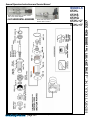
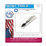
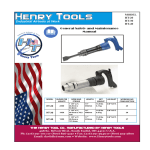
MODELS
65 HL
65 HS
65 HG
General Safety and Maintenance Manual 65 HL+2”
65 HL+3”
4 H.P HORIZONTAL GRINDERS
CAPACITY
-6 Inch (150 mm) or 8 Inch
(200 mm) Type 1 Wheels
-Any Type 16, 17, 17R, 18 or 18R
Cone Wheels w/ 5/8-11 Mounting
65H Series 4 H.P HORIZONTAL GRINDERS
Model
No.
Rated
Power
Rated
Speed
Spindle
Type and
Thread
(L) Lever
or (K)
Safety
Lever
65H
65HS
Throttle
Type
4.0 H.P
3.0 KW
(K) Safety
Lever
65HK
(K) Safety
Lever
65HG
(G) Spade
Handle
Weight
ALUM
Overall
Lenght
Working
Air Consumption
12.5 Lbs
(5.7 Kg)
4500 8000RPM
22.1
Inches
(561 mm)
T1 - 5/8-11
X 1.9
50 cfm
(23.6 L/s)
13.5 Lbs
(6.1 Kg))
The Henry Tool Co., Manufactured by Henry Tools
498 So. Belvoir Blvd., South Euclid, OH 44121 U.S.A.
Ph: (216) 291-1011 or (800) 826-5257 ● Fax: (216) 291-5949 or (800) 303-2800
Email: [email protected] ● Website: www.Henrytools.com
Spindle
Length
&
Thread
5/8-11
X 0.9
Inch
(5/8-11
X 23
mm)
Model 65H Horizontal grinder shown
with cone wheel adaptor.
Model 65H Horizontal grinder
shown with 8” Guard
Ph:
4 H.P HORIZONTAL GRINDERS
MODELS
65 HL
65 HS
65 HG
65 HL+2”
65 HL+3”
HENRY TOOLS, INC. (216) 291-1011 or (800) 826-5257
General Operators Instructions and Service Manual
www.HenryTools.com | Page 337
For additional product information visit our website.
Revised 02/26/12
Model 65H Horizontal grinder shown
with cone wheel adaptor.
DESCRIPTION
700-37
Cylinder Pin
650-1-H
FRONT SPINDLE HOUSING
650-1-HC
MOTOR HOUSING
700-11
CYLINDER (PINS INSTALLED)
700-16
REAR ENDPLATE
700-12
ROTOR
700-13
ROTOR BLADE (4 REQ.)
700-10
FRONT ENDPLATE
650-8-H
SPINDLE (STANDARD LENGTH TYPE 1)
650-8-H+2
Spindle +2” Length
650-8-H+3
Spindle +3” Length
550-9-H
FRONT BEARING PAIR
550-10-H
CENTER BEARING
550-11-H
SNAP RING
700-15
KEY
650-13
GASKET
600-48
GOV. PIN RETAINER
650-H-13
FRONT BEARING CAP
650-H-14
SEAL
700-4
WHEEL FLANGE(6 INCH WHEELS)
700-4D
WHEEL FLANGE(8 INCH WHEELS)
700-5
DRIVE FLANGE(6 INCH WHEELS)
700-5D
DRIVE FLANGE(8 INCH WHEELS)
700-4-CWA
CONE WHEEL ADAPTOR (UNTHREADED I.D.)
700-4-CWB
CONE WHEEL ADAPTOR (THREADED I.D.)
700-9
BEARING
700-34
SPINDLE NUT
700-37
PART NO.
DESCRIPTION
700-66A
6 INCH TYPE 1 WHEEL
GUARD(Same as 650-HS-56A)
700-68A
8 INCH TYPE 1 WHEEL GUARD
(Same as 650-HS-58A)
GOVERNORS
AA-550-30
GOVERNOR ASSY. (3000 RPM)
AA-550-45
GOVERNOR ASSY. (4500 RPM)
AA-550-60
GOVERNOR ASSY. (6000 RPM)
(standard)
AA-550-80
GOVERNOR ASSY. (8000 RPM)
WRENCHES
1100-200
2” Wrench
REPAIR KITS
510082
REPAIR KIT: INCLUDES BEARINGS,
ROTOR BLADES, SNAP RINGS AND
GASKETS.
Ph:
PART NO.
Model 65H Horizontal grinder
shown with 8” Guard
MODELS
65 HL
65 HS
65 HG
65 HL+2”
65 HL+3”
CYLINDER PIN
700-46
WASHER (4 REQ.)
700-47A
SCREW (4 REQ.)
1000-5
LOCK RING
540619
WHEEL FLANGE(8 INCH WHEELS)
(same as 700-4D)
540620
DRIVE FLANGE(6 INCH WHEELS)
(Same as 700-5D)
GUARDS
650-HS-56A 6 INCH TYPE 1 WHEEL
GUARD(Same as 700-66A)
650-HS-58A 8 INCH TYPE 1 WHEEL GUARD
(Same as 700-68A)
www.HenryTools.com | Page 338
HENRY TOOLS, INC. (216) 291-1011 or (800) 826-5257
General Operators Instructions and Service Manual
For additional product information visit our website.
Revised 02/26/12
Model 65H Horizontal grinder
shown with 8” Guard
Ph:
Model 65H Horizontal grinder shown
with cone wheel adaptor.
MODELS
65 HL
65 HS
65 HG
65 HL+2”
65 HL+3”
HENRY TOOLS, INC. (216) 291-1011 or (800) 826-5257
General Operators Instructions and Service Manual
Part Number
Description
200-9
O-Ring
500-46
Snap Ring
550-33-L
550-33-SW
Part Number
Description
AA-650-1-ALS
Safety Lock Handle Assembly
(Complete)
Live Handle Adaptor bushing
650-33
Screen Bushing(1/2x3/8)
Screen Filter
650-54
Safety Lock Pin
550-33-SP
Spacer
650-55
Safety Lock Spring
550-38
Lever
650-56
Safety Lock Lever
550-50
Lever Pin
650-57
Set Screw
560-13
Throttle Valve Assembly
with 200-9 O-ring installed
700-30
O-Ring
700-48
Cap Screw
Plunger Spring
700-54
Lock Washer
Live Handle Body (Non-Lockout type)
700-S-26
Plug
650-1-ALS
Safety Lock Valve Body(Bare)
700-G-26-GK
Gasket
AA-650-1-AL
Handle Assembly (Complete)
(Non-lockout handle)
841555
Screen Bushing (1/2X1/2)
600-51
650-1-AL
www.HenryTools.com | Page 339
For additional product information visit our website.
Revised 02/26/12
MODELS
65 HL
65 HS
65 HG
65 HL+2”
65 HL+3”
Model 65H Horizontal grinder
shown with 8” Guard
Model 65H Horizontal grinder shown
with cone wheel adaptor.
such that opening in guard is
away from operator.
Ph:
Before using or after mounting a
wheel, the tool must be run for
one minute in protected enclosure to check the integrity of the
wheel.
HENRY TOOLS, INC. (216) 291-1011 or (800) 826-5257
General Operators Instructions and Service Manual
INSPECT THE WHEEL OR ACCESSORY
Check the maximum safe RPM marked on the wheel or accessory.
Never use a wheel or accessory rated below the actual tool speed. Cracked,
dropped, faulty, or bent accessories are dangerous. Suspect accessories
should not be used and should be disposed of. Inspect wheel for cracks or
chips, water stains, or signs of abuse or improper storage Cracked or faulty
grinding wheels are dangerous. They must be destroyed rather than risk their
use by someone who may not notice that they are damaged.
Never operate a grinder without a wheel guard. Guard must not be modified,
and any guard damaged or bent must be replaced. Grinder must be used
www.HenryTools.com | Page 340
For additional product information visit our website.
Revised 02/26/12
Model 65H Horizontal grinder
shown with 8” Guard
DISASSEMBLY
1. Disconnect air & remove all wheels and accessories.
2. Remove the wheel guard by removing the two screws which
clamp it to the case.
3. Hold the hand grip portion of the case in a vise and remove the
four socket head cap screws (700-47A) and washer (700-46) The
governor housing (650-1-HC) can now be removed.
4. Holding the arbor (650-8H) in a vise, unscrew the governor
assembly (turn clockwise to remove the governor) (left hand
thread).
5. Remove from vise, remove snap ring (1000-5). Using a 1/4
punch tap out spindle where governor was. Do not damage
internal threads on spindle. This will cause the cylinder (700-11),
rotor(700-12) and rear thrust(700-16) to slide out.
6. Next remove key from the arbor , which will allow the front
thrust (700-10) to be removed.
7. Replace key in arbor, using brass vise grips, remove flange
(700-5/540620) (right hand thread.)
8. Remove from vise and reclamp vise on housing (650-1H). Unscrew bearing cap (650-H-13).
9. Remove from vise and remove snap ring (550-11H) with proper
pliers.
10. With arbor press - press out spindle on threaded end of spindle
-removing bearing (550-1OH). Remove double bearing (550-9H).
11. The only part of the valve which will require replacement is the
o-ring (200-9). To replace this ring, unscrew plug (700-S-26) and
lift out valve spring (600-51) and plunger (560-13). Remove the o
ring with sharp tool and replace with a new ring (200-9).
REASSEMBLY
1. Slip the two bearings (550-9H) into housing (650-1-H). Screw
on the cap (650-H-13).
2. Invert housing and press arbor (650-8H) into the housing, being careful to fully support front double bearing. Press on bearing
(550-1OH) until it bottoms on shoulder of the housing. Replace
snap ring (550-11H).
3. Clamp housing (650-1-H) in vise and screw on bearing cap
(650-H-13) with wrench.
4. Place key (700-15) in arbor. Grip arbor and key in vise jaws to
protect surfaces. Screw down and tighten flange (700-5/540620)
(Right hand threads).
5. Remove from vise.Remove key. Place front thrust(700-10) on
arbor. Replace key.
6. Place housing in vise-locating on the flats of the flange (7005/540620).
7. Slip rotor (700-12) on arbor aligning keyway with key in arbor.
Drop in blades (700-13).
8. Drop in cylinder (700-11), making sure that the long dowel(700-37) goes through the hole in front thrust and the small hole
in housing. Install rear thrust(700-16) placing small hole over pin
(700-37A).
9. Press bearing (700-9) into rear endplate with bearing suitable
bearing driver.
10. Install lock ring (1000-5) onto spindle with use of snap ring
pliers.
www.HenryTools.com | Page 341
(There is no groove.)
11. Prior to reassemble inspect governor for
gouges, nicks or dents.
Oil the governor and inside of motor. Screw governor (AA-550-XX) into
end of spindle and tighten with wrench. (left
handthread).
12. Assemble live handle/spade handle if this was
inspected or repaired.
13. Install live and dead handles to case (650-1HC).
14. Secure motor housing in a vise with handle
toward downward direction. Clamp vise onto the
live handle (AA-650-1-AL) or spade handle (AA550-H-3).
15. Place gasket (650-13) in rear face of case.
16. Slide the motor lightly and STRAIGHT into
case. The motor assembly must be kept straight
to install into the case easily.
17. Install 4 bolts (700-47A) and lock washers
(700-46). Tighten bolts down until snug then back
off 1/2 turn.
18. Connect tool to air supply and apply air in
several short bursts.
19. Now run tool and tighten down bolts evenly.
(Alternating from corner to corner.)
20. Attach Guard to the tool. DO NOT OPERATE your model 65H grinder without a wheel
guard.
Check RPM with a reliable tachometer. Tool must
run at or below speed stamped on the tool.
This tool is designed to operate on 90 psig (6.2
bar) maximum air pressure with 1/2” (12.7mm)
hose.
Do not use a grinder without recommended wheel
guard. Do not use any wheel for which the
operating speed listed is lower than the actual free speed on the grinder.
SAFETY
1. Before operation check spindle speed with a
tachometer. If the RPM’s exceed the rated speed
stamped on tool, servicing is required.
2. Inspect grinding wheels for bends, chips, nicks,
cracks or severe wear. If the wheel has any of
these, or has been soaked in liquids do not use.
On brushes check for loose wires that may fly off
in operation.
3. Start new grinding wheels under a steel bench.
Run at full throttle for one minute. Defective
wheels usually come apart immediately. When
starting a cold wheel apply to the work slowly, al-
For additional product information visit our website.
Revised 02/26/12
Ph:
Model 65H Horizontal grinder shown
with cone wheel adaptor.
MODELS
65 HL
65 HS
65 HG
65 HL+2”
65 HL+3”
HENRY TOOLS, INC. (216) 291-1011 or (800) 826-5257
General Operators Instructions and Service Manual
Model 65H Horizontal grinder
shown with 8” Guard
Model 65H Horizontal grinder shown
with cone wheel adaptor.
SAFETY (continued)
MODELS
65 HL
65 HS
65 HG
65 HL+2”
65 HL+3”
low wheel to warm up gradually.
4. Safety lock levers are available from the manufacturer (6501-ALS).
5. Before mounting or removing a wheel disconnect grinder
from air supply. The wheel should fit properly on arbor; do not
use bushings or wheel flanges to adapt a wheel to any arbor
unless recommended by manufacturer.(Wheel flanges should
be at least 1/3 the diameter of the grinding wheel.)
6. Wear safety goggles and other protective clothing (when
necessary).(See regulations.)
7. Properly maintained air tools are less likely to fail or cause
accidents. If tool vibrates or produces an unusual sound, repair
immediately.
WARNING
Do not disassemble the governor. The governor is guaranteed
for the life of the tool if it is not abused. Prior to reassembly
inspect governor for gouges, nicks or dents.
www.HenryTools.com | Page 342
For additional product information visit our website.
Ph:
LUBRICATION
1. An air line filter-regulator-lubricator should be located as
closely as possible to the tool.
2. Clean out dirt and moisture from air hoses daily. Keep
screen handle bushing in tool.
3. OIL TOOLS DAILY. Exxon’s Spinesstic 10, Atlantic Richfield’s
Duro 55, Gulf’s Gulfspin 10 or an equivalent is recommended.
Pour about 1 tablespoon in air inlet and run tool to allow oil to
be carried to the interior.
Additional safety information is available from the American
National Standards Institute, Inc., 1430 Broadway, New York,
N.Y. 10013 (ANSI B186.1)
HENRY TOOLS, INC. (216) 291-1011 or (800) 826-5257
General Operators Instructions and Service Manual
Revised 02/26/12