1
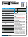
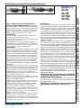
MODELS
52 HL
52 HS
52 HSJ
General Safety and Maintenance Manual 52 HG
MODEL 52H HORIZONTAL GRINDER WITH 6” GUARD
MODEL 52HG HORIZONTAL GRINDER WITH 6” GUARD
MODEL 52HSJ HORIZONTAL GRINDER WITH
CONE WHEEL INSTALLED.
2 H.P. HORIZONTAL GRINDERS
Model
Throttle
Type
Rated Speed
Power
Output
Case
Material
52HSJ
52HG
STEEL
Overall
Lenght
8.3 Lbs
(3.8 Kg)
52HL
52HS
Weight
(L) Lever or
(K) Safety
Lever
(G) Spade
Grip Handle
6000,9000. or
12,000
R.P.M.
2.0 H.P.
(1.5
KW)
(S)
Steel or
Aluminum
Working
Air Consumption
40 cfm
(18.9
L/s)
21.3 Inches
(546 mm)
Spindle Length &
Thread
T1 - 5/8-11 X 2.1
Inch (53.3 mm)
CW - 5/8-11 X 0.9
Inch (23 mm)
9.3 Lbs
(4.2 Kg)
The Henry Tool Co., Manufactured by Henry Tools
498 So. Belvoir Blvd., South Euclid, OH 44121 U.S.A.
Ph: (216) 291-1011 or (800) 826-5257 ● Fax: (216) 291-5949 or (800) 303-2800
Email: [email protected] ● Website: www.Henrytools.com
Model 52H grinder wih 6” Guard.
GOVERNOR
Model 52HSJ grinder wih Cone Wheel installed.
MODELS
52 HL
52 HS
52 HSJ
52 HG
RPM
6000
510067
9000
510069
12000
Ph:
510066
HENRY TOOLS, INC. (216) 291-1011 or (800) 826-5257
General Operators Instructions and Service Manual
www.HenryTools.com | Page 308
For additional product information visit our website.
Revised 02/19/12
Model 52HSJ grinder wih Cone Wheel installed.
LIVE HANDLE ASSEMBLY
Part Number
200-9
500-46
550-33-L
550-33-SW
550-33-SP
550-38
550-50
560-13
600-51
650-1-AL
650-1-ALS
650-33
650-54
650-55
650-56
Description
O-Ring
Snap Ring
Live Handle Adaptor bushing
Screen Filter
Spacer
Lever
Lever Pin
Throttle Valve Assembly
with 200-9 O-ring installed
Plunger Spring
Live Handle Body (Non-Lockout type)
Safety Lock Valve Body(Bare)
Screen Bushing(1/2x3/8)
Safety Lock Pin
Safety Lock Spring
Safety Lock Lever
www.HenryTools.com | Page 309
Part Number
650-57
700-30
700-48
700-54
700-S-26
700-S-26-GK
841555
ASSEMBLIES
AA-650-1-AL
Description
Set Screw
O-Ring
Cap Screw
Lock Washer
Plug
Gasket
Screen Bushing (1/2X1/2)
Handle Assembly (Complete)(Nonlockout handle)
AA-650-1-ALS Safety Lock Handle Assembly (Complete)
For additional product information visit our website.
Revised 02/19/12
Ph:
Model 52H grinder wih 6” Guard.
MODELS
52 HL
52 HS
52 HSJ
52 HG
HENRY TOOLS, INC. (216) 291-1011 or (800) 826-5257
General Operators Instructions and Service Manual
Model 52HSJ grinder wih Cone Wheel installed.
PART NO.
DESCRIPTION
540258
RETAINER CAP (52H)
510066
GOVERNOR (6000RPM)STANDARD
540595
BACKHEAD (Model 52H)
510067
GOVERNOR (9000 RPM)
596001
OIL SEAL (52H)
510069
GOVERNOR (12000RPM)
842627
ROTOR LOCK NUT (52H)
REPAIR KITS
844363
FRONT ROTOR BEARING (52H0
510112
844990
CYLINDER ROLL PIN (52 Series)
847528
BEARING (52H)
847946
COLLAR RETAINER (52H)
864515
ROTOR COLLAR (52H)
864522
REAR ROTOR BEARING (52H)
864524
FRONT ARBOR BEARING (52H)
864525
5/8 ARBOR COLLAR
864562
ROTOR BLADE (52 Series)
867170
GOVERNOR SEAT
867367
ROTOR (52 Series)
867369
REAR BEARING PLATE (52 Series)
867370
RUBBER SLEEVE (52H)
867371
COUPLING (52H)
867372
EXHAUST DEFLECTOR (52H)
867377
CYLINDER WITH ROLL PINS (52 Series)
867378
HOUSING (52H)
867381
SPINDLE (5/8-11 STUB SPINDLE) for
MOUNTING CONE WHEELS APPLICATIONS
(52H)
867382
SPINDLE (5/8-11 x 2 1/4”) LONG (52H)
867386
O-RING (52H)
867483
SNAP RING (52H)
867484
KEY
882885
FRONT END PLATE (52H)
700-34
NUT
700-4
6” WHEEL WASHER
700-4-CWA
CONE WHEEL ADAPTOR
GUARDS
5206-1
GUARD 6” (52H series)
WRENCHES
1100-094
15/16” WRENCH
110-181
1 13-16” WRENCH
www.HenryTools.com | Page 310
GOVERNORS
REPAIR KITS INCLUDES ALL BEARINGS,
ROTOR BLADES and SNAP RINGS
OPERATION
The 52H series horizontal grinder is designed to operate
on 90 psig maximum air pressure. The tool is equipped
with a 1/2” NPT air inlet bushing and will operate satisfactorily on a 1/2” hose up to 8’ in length.
OPERATING SAFETY
CAUTION
ALWAYS HAVE THE PROPER WHEEL GUARD ATTACHED
TO THE GRINDER. NEVER MODIFY ANY PART OF
THIS GRINDER OR IT”S ACCESSORIES.
Read, understand, and practice the requirements of
A.N.S.I. B186.1-1975, Safety Code for Portable Air
Tools. This standard is available from the American
National Standards Institute, Inc., 1430 Broadway, New
York, New York 19918 .
ALWAYS WEAR IMPACT-RESISTANT EYE AND
FACE PROTECTION WHEN INVOLVED lN OR NEAR
THE OPERATION OF ABRASlVE TOOLS. (SEE THE
LATEST EDITION OF ANSI Z84.4, AMERICAN NATlONAL
STANDARD FOR OCCUPATIONAL AND EDUCATIONAL
EYE AND FACE PROTECTION.
The Grinder free speed should be checked daily (before
beginning operations) with a dependable tachometer
with the grinding wheel removed. The rated rpm of the
tool is stamped on the tool name plate.
Check each new wheel or disc for maximum safe speed
and soundness. Keep all persons out of line with wheel
or disc whenever starting tool.
IMPORTANT: BEFORE MOUNTING (OR REMOVING) ANY
ABRASIVE WHEEL, THE TOOL SHOULD BE DISCONNECTED FROM THE AIR SUPPLY LINE.
GRINDING WHEEL SELECTION
CRACKED OR FAULTY GRINDING WHEELS OR DISCS
ARE DANGEROUS AND SHOULD NOT BE USED. Care
must be exercised in the installation of the wheel and
handling of the tool with grinding wheel attached. We
recommend that you exercise caution when selecting
the proper grinding wheel for use with your grinder and
for work to be performed. Both efficiency and safety
depends upon your proper selection of the grinding
wheel. Never use a wheel rated below the actual tool
free speed.
For additional product information visit our website.
Revised 02/19/12
Ph:
Model 52H grinder wih 6” Guard.
MODELS
52 HL
52 HS
52 HSJ
52 HG
HENRY TOOLS, INC. (216) 291-1011 or (800) 826-5257
General Operators Instructions and Service Manual
Model 52HSJ grinder wih Cone Wheel installed.
NOTE: ALWAYS CHECK THE RPM BEFORE INSTALLING A NEW GRINDING WHEEL. Upon mounting the new wheel, the tool should be run at operating
speed (minimum one (1) minute) with the safety guard
in place making sure that no one is in the unguarded
plane of wheel rotation) or in a protective enclosure to
insure the balance and integrity of the wheel.
LUBRICATION
1. An air line filter regulator-lubricator should be located as closely as possible to the tool.
2.Clean out dirt and moisture from air hoses daily. Keep
screen handle bushing in tool.
3.OIL TOOLS DAILY. Exxon’s Spinesstic 10,Atlantic
richfield’s Duro 55, Gulf’s Gulfspin 10 or an equivalent
is recommended. Pour about 1/2oz. in air inlet and run
tool to allow oil to be carried to the interior.
DISASSEMBLY
Slip the rubber grip, (867370), forward expose the flats
on Ihe housing(867378), Clamp the housing in a soft
jawed vise with the handle up and unscrcw the handle
assembly. The complete motor unit may now be slipped
out the rear of the housing. Remove the housing from
the vise and unscrew the arbor nut. This will allow the
arbor washer, collar retainer, arbor collar, and arbor key
to be removed from the the arbor. This completes disassembly of the tool into three (3) major assemblies.
See the following paragraphs for complete disassembly
instructions.
HOUSING: Clamp the housing in the vise and unscrew
(left hand threads) the arbor bearing retainer(540258).
This will allow the arbor with attached components to
be removed from the front of the housing. Remove the
coupling(867371), from the rear of the arbor. If replacement of the arbor bearings is necessary, they may
be pressed off the arbor shaft.
MOTOR: Clamp the rotor lock nut (842627), in the vise
with the governor assembly up. Unscrew the governor
(867170)(LEFT HAND THREAD).
Remove the motor unit from the vise and clamp on the
cylinder with the threaded end of the rotor up. Drive
the rotor (867367), out of the rear bearing (864522),
being careful not to damage the threads. Remove
the cylinder (867377), and three (3) rotor blades
(864562), from the rotor. Clamp the body of the rotor
in the vise with the splined end up and unscrew the rotor lock nut. This will allow the rotor to be driven out of
the front rotor bearing (844363).
HANDLE:. The only part of the valve which may require
replacement is the o-ring 200-9. To replace this ring,
unscrewplug 700-S-26 and lift out valve spring 600-51
and plunger 560-13. Remove the o-ring with sharp tool
and replace with a new ring.
www.HenryTools.com | Page 311
REASSEMBLY
The tool is reassembled in the reverse order of disassembly.
All parts should be thoroughly cleaned and inspected fro wear
before reassembly. Particular attention should be paid to the
rotor blades and all bearings as failure of these parts could
cause damage to the more expensive components. Rotor
blades should be replaced if they measure less than 5/16” at
either end. Ball bearings should be replaced if they are rough
or show excessive looseness. Pack bearings with a generous
amount of No.2 Moly grease before reassembly. ALL BEARINGS
SHOULD BE INSTALLED WITH THE SHIELDED SIDE TO THE
REAR OF THE TOOL.
HOUSING: Install the front arbor bearing(864524) by pressing on to shaft. If you are replacing the seal(596001), press
the seal into arbor bearing retainer (540258). When installing
the arbor bearing retainer(540258), apply grade “CVV” Loctite
(blue) to the threads (left hand) before screwing it into the
housing. The retainer should then be torqued to 75-85 ft lbs.
MOTOR: During reassembly of the motor, the rotor must be positioned by the rotor collar(864515), so that when assembled,
the rotor will have .001” to .002” clearance between it and
the front bearing plate. To set the rotor collar, assemble the
front rotor bearing in to the front bearing plate and measure
the depth of the inner race from the face of the bearing plate.
Select, or fit by sanding, a rotor collar .001” to
.002” larger than this dimension. Clamp the rotor body in the
vise (spline end up) and slip the rotor collar, chamfered side
first, on the rotor shaft and drive the bearing plate and bearing
(DRIVE ON THE INNER RACE) down on the rotor collar. Screw
the rotor lock nut (842627), down and torque to 50-60 ft. lbs.
The governor (left hand thread) should now be installed and
torqued to 15-20 ft.lbs. during reassembly.
AFTER REASSEMBLY OF THE COMPLETE TOOL, THE RPM WILL
NEED TO BE CHECKED.
CAUTION: BE SURE TO CHECK THE TOOL FOR PROPER
SPEED WITH A DEPENDABLE TACHOMETER BEFORE RETURNING THE TOOL TO SERVICE.
To adjust the rpm, rotate the governor adjusting ring, in a
clockwise direction to increase the rpm and counterclockwise
direction to lower the rpm.
Reinstall all safety devices especially the wheel
guard before returning the tool to service.
For additional product information visit our website.
Revised 02/19/12
Ph:
Model 52H grinder wih 6” Guard.
MODELS
52 HL
52 HS
52 HSJ
52 HG
HENRY TOOLS, INC. (216) 291-1011 or (800) 826-5257
General Operators Instructions and Service Manual