1
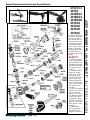
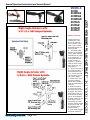
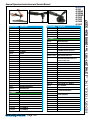
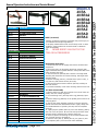
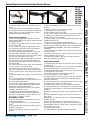
MODELS
48 RA
48 BRA2
48 BRA4
General Safety and Maintenance Manual 48 BRAD
48 RAS
48 RAZ
48 RAD
48 RAC
Model
Number
Exhaust
Direction
Throttle
Type
Speed
Power
Output
Weight
Alum.
CASE
STEEL
CASE
Overall
Length
Housing
Diameter
Working
Air
Consumption
3/8-24 x
0.98 Inch (25
mm)
48BRA
48BRAZ
Front
or
Side
48BRAC
48BRAD
Spindle
Thread
& Length/
Output
(L)
Lever
or
(K)
Safety
Lever
9000
to
11000
R.P.M.
(11000
is Standard)
5/8-11 x
0.98 Inch (25
mm)
0.9 H.P.
(675 W)
2.8 lb
(1.3
Kg)
3.5 lb
(1.6
Kg)
9.2
Inches
(234
mm)
1.6
Inches
(41 mm)
25 cfm
(11.8 L/S)
Wheel
Capacity
2 Inch (50 mm), 3
Inch (75 mm),
4 inch (100 mm),
4 1/2 inch (114
mm),
5 inch (125
mm) or
6 Inch (150 mm)
Type 1 Cutoff or
Type 27 Wheels
1/4 Inch
Built-In
Collet
1/4 Inch Burrs/
Mounted Points
Changeable
Insert Collet
(ERICKSON
TYPE)
Burrs/Mounted
points Matching
the Insert Size
The Henry Tool Co., Manufactured by Henry Tools
498 So. Belvoir Blvd., South Euclid, OH 44121 U.S.A.
Ph: (216) 291-1011 or (800) 826-5257 ● Fax: (216) 291-5949 or (800) 303-2800
Email: [email protected] ● Website: www.Henrytools.com
This tool is designed
to operate on 90 psig
(6.2 bar) maximum
air pressure with 1/4”
(8 mm) hose. Do not
use a grinder without
recommended wheel
guard. Do not use any
wheel for which the
operating speed listed
is lower than the actual free speed of the
Grinder.
SAFETY
1. Before operation
check spindle speed
with a tachometer. If
the RPM exceeds the
rated speed stamped
on tool, servicing is
required.
2. Inspect grinding
wheels for bends,
chips, nicks, cracks
or severe wear. If
the wheel has any of
these, or has been
soaked in liquids do
not use. On brushes
check for loose wires
that may fly off in
operation.
3. Start new grinding
wheels under a steel
bench. Run at full
throttle for one minute. Defective wheels
usually come apart
immediately. When
starting a cold wheel
apply to work slowly,
allow wheel to warm
gradually.
4. Model 48RAC
grinders equipped
with collets are intended for mounted
www.HenryTools.com | Page 100
For additional product information visit our website.
Revised 02/19/12
Ph:
MODELS
48 RA
48 BRA2
48 BRA4
48 BRAD
48 RAS
48 RAZ
48 RAD
48 RAC
HENRY TOOLS, INC. (216) 291-1011 or (800) 826-5257
General Operators Instructions and Service Manual
SAFETY (continued)
wheels,points and
carbide burrs. They
are not guarded for
type 1 wheels. If you
have a type 1 wheel
application,please purchase a guard.
5. The Model 48RA
Grinders are equipped
with a guard from the
manufacturer. A guard
is not needed for :a.)
mounted wheels two
inches (50 mm) or
smaller; b.) grinders
used for internal work,
while within the work
being ground.
6. At least one-half of
the mandrel length (i.e.
mounted wheel, burr,
etc.) must be inserted
into the collet. Secure
collet chuck tightly.
7. Safety levers that
prevent accidental
startup are available
from the manufacturer.
(402-26).
8. Before mounting
or removing a wheel,
disconnect grinder from
air supply. The wheel
should fit properly on
arbor, do not use bushings or wheel flanges
to adapt a wheel to any
arbor unless recommended by the manufacturer. (Wheel flanges
should be at least 1/3
the diameter of the
grinding wheel.)
9. Wear safety goggles
and other protective
www.HenryTools.com | Page 101
For additional product information visit our website.
Revised 02/19/12
Ph:
MODELS
48 RA
48 BRA2
48 BRA4
48 BRAD
48 RAS
48 RAZ
48 RAD
48 RAC
HENRY TOOLS, INC. (216) 291-1011 or (800) 826-5257
General Operators Instructions and Service Manual
MODELS
48 RA
48 BRA2
48 BRA4
48 BRAD
48 RAS
48 RAZ
48 RAD
48 RAC
PART NUMBER
DESCRIPTION
PART NUMBER
DESCRIPTION
209-1
COLLET NUT
1100-063
5/8” WRENCH
209-1/8
1/8” INSERT
1100-068
11/16” WRENCH
1/4” INSERT
1100-075
3/4” WRENCH
209-3/8
3/8” INSERT
1100-094
15/16” WRENCH
300-G-29
BEARING
400-G-11
FRONT BEARING
400-G-26
THROTTLE LEVER
510240
MOTOR REPAIR KIT
400-G-29
THROTTLE VALVE-INCLUDES 844302
510230
ANGLE HEAD REPAIR KIT
400-G-34
SPRING
402-26
SAFETY LEVER ASSY.
400-G-42
3/8-24 FLANGE (2”-3” WHEELS)
AA-402-132
ALUMINUM CASE ASSY.
400-G-47
3/8-24 JAM NUT
AA-402-132-K
400-2G
CYLINDER
CASE ASSY.
ALUMINUM SAFETY CASE ASSY.
400-5
ROTOR
AA-402-132-S
STEEL CASE ASSY.
BLADE (5 REQ.)
AA-402-132-SK
STEEL SAFETY CASE ASSY.
400-7
FRONT ENDPLATE
AA-408-1;D
400-10
KEY
400-44
ROLL PIN
(SPECIFY SPEED FOR CASE ASSY.)
ERICKSON 48RAANGLE HEAD ASSY.
(SPECIFY INSERT SIZE)
400-46
SNAP RING
404-39
SNAP RING
400-51
0-RING
404-40
DEAD HANDLE
402-126
SAFETY LEVER
406-14A
MOTOR SPINDLE
402-127
SAFETY LEVER PIN
406-38
LOCKNUT
402-128
LOCKOUT LEVER
406-39
MOTOR RETAINER
402-129
SAFETY LEVER SPRING
406-40
HEAD RETAINER
402-132
ALUMINUM CASE (SPECIFY SPEED)
406-41
COUPLING
402-132-S
STEEL CASE (SPECIFY SPEED)
406-42
SPACER
402-134
MUFFLER
408-1
Gear Head {same as part #4041-1}
404-4
KEY
410-G-17-S
STEEL SIDE EXHAUST SLEEVE
404-7
LOWER OUTPUT SPINDLE BEARING
500-G-44
3/8 ID FLANGE (4”-5” WHEELS)
404-9
REAR MOTOR BEARING
700-34
5/8-11 JAM NUT
404-19
REAR ENDPLATE
700-37
Throttle Lever Pin
404-38
BEARING COVER
1100-680
5/8 I.D. FLANGE
(6” OR SMALLER WHEELS)
1100-682
`
3/8 I.D. FLANGE (5”-6” WHEELS)
OUTPUT HOUSING
4041-5
3/8-24 X .980 OUTPUT SPINDLE
4041-9
GEAR SPACER
4041-10
GEAR SET
4041-13
BEARING COVER
4041-14
SNAP RING
4041-17-625
5/8-11 X .980 OUTPUT SPINDLE
4041-17-DA
ERICKSON COLLET SPINDLE
400-6
GUARDS
4503
3” TYPE 27 GUARD
4504
4” TYPE 27 GUARD
4505
5° TYPE 27 GUARD
4506
6” TYPE 41 GUARD
490-3
PIN SPANNER
102-SPWR
WRENCH FOR SANDING PAD NUT
1100-044
7/16’ WRENCH
1100-056
9/16’ WRENCH
www.HenryTools.com | Page 102
ASSEMBLIES
For additional product information visit our website.
Ph:
209-1/4
HENRY TOOLS, INC. (216) 291-1011 or (800) 826-5257
General Operators Instructions and Service Manual
Revised 02/19/12
DESCRIPTION
591100
SCREW
591106
SET SCREW (SPECIFY SPEED)
592016
SNAP RING
594016
0-RING
832636
GASKET
841552
3/8 NPT TO 3/8 NPT BUSHING
841553
3/8 NPT TO 1/4 NPT BUSHING
844302
0-RING
869311
THROTTLE VALVE CAP
ACCESSORIES
PART NUMBER
DESCRIPTION
400-78
3/8-24 TO 5/8-11 ADAPTER
405-24
BACKING PLATE FOR 490-KR
490-K
3/8-24 X .980 TYPE 27 ADAPTER
ASSY.
490-KR
3/8-24 X .580 TYPE 27 ADAPTER
ASSY.
490-1
BACKING PLATE FOR 490-K
490-2
NUT FOR 490-K & 490-KR
1100-660
3/8-24 TO 5/8 I.D. TYPE 27
ADAPTER ASSY.
1100-661
3/8-24 TO 5/81.D. BACKING PLATE
1100-662
3/8-24 TO 5/8 I.D. ADAPTER NUT
1100-664
3/8-24 TO 7/8 I.D. BACKING PLATE
1100-666
3/8-24 TO 7/8 I.D. ADAPTER NUT
1100-668
3/8-24 TO 7/8 I.D. TYPE 27
ADAPTER ASSY.
1100-692
5/8-11 TO 7/8 I.D. TYPE 27
ADAPTER ASSY.
1100-694
5/8-11 TO 7/8 I.D. BACKING PLATE
1100-696
5/8-11 TO 7/8 I.D. ADAPTER NUT
849259
5/8-11 SANDING PAD NUT
849259-A
3/8-24 SANDING PAD NUT
889271
5/8-11 4” SANDING PAD
(MAX 12000 RPM)
889271-A
3/8-24 4” SANDING PAD
(MAX 12000 RPM)
849848
5/8-11 5” SANDING PAD
(MAX 10000 RPM)
849913
5/8-11 7” SANDING PAD
(MAX 8500 RPM)
www.HenryTools.com | Page 103
SAFETY (continued)
clothing. Continuous exposure to vibration may cause injury to
your hands and arms.(See regulations.)
10.Properly maintained air tools are less likely to fail or cause
accidents. If tool produces an unusual sound or vibrations
repair immediately.
11.
NEVER MODIFY ANY PART OF THE
TOOL OR ACCESSORIES!!
Disassembly First Steps
1. Disconnect tool from air supply and remove all wheels and
accessories.
2. Secure the tool in an aluminum jawed vise vertically with
angle head toward the upward direction. Clamp onto flats of the
motor housing (402-132).
3. Unscrew lock nut (406-38) with a wrench. The angle head
assembly will disconnect from motor housing. Set angle head
assembly aside.
4. Remove coupling (406-41), exhaust sleeve (410-G-17S), oring (400-51) and exhaust screen (402-134).
5. Unscrew and remove motor retainer (406-39) carefully on
flats with wrench.
6. Pull motor assembly out of motor housing. Remove from vise.
The Motor Disassembly
7. Remove snap ring (404-39) if present from rear of motor assembly with use of snap ring pliers.
8. Lift out bearing cover (404-38) and o-ring (594016) if present.
9. Remove snap ring (592016) out of spindle groove with use of
snap ring pliers.
10. Secure the motor assembly vertically in the vise with the
geared end toward the downward direction. Lightly clamp onto
the outside diameter of cylinder (400-2G) and rear endplate
(404-19).
11. Lightly tap the spindle (406-14) out of rear bearing (404-9)
with use of a 3/16” punch. Be sure not to drop the front motor
assembly when it becomes free. Remove from vise.
12. Push or tap the rear bearing out of the read endplate with
use of a small punch or screwdriver.
13. Remove rotor (400-5), blades (400-6), key (400-10) and
front endplate (400-7) from the front motor assembly.
For additional product information visit our website.
Revised 02/19/12
Ph:
PART NUMBER
MODELS
48 RA
48 BRA2
48 BRA4
48 BRAD
48 RAS
48 RAZ
48 RAD
48 RAC
HENRY TOOLS, INC. (216) 291-1011 or (800) 826-5257
General Operators Instructions and Service Manual
Angle Head Disassembly
16. Secure right angle head assembly in vise so
that the angle head neck is vertical. Clamp onto the
dead handle bosses.
17. Remove head retainer (406-40) using a wrench
on the wrench flats.
18. Lift off lock nut. Remove angle head from vise.
19. Grasp end of pinion gear (406-112) and pull
pinion gear assembly from angle head.
20. Secure the pinion gear assembly in vise vertically with gear head (4041-110) in downward
direction. Clamp onto the side of gear spacer (40642) and rear most bearing (300-G-29).
21. Tap the pinion gear stem through the rear bearing with use of a 3/16”punch. Remove from vise.
22. Secure the pinion gear stem with a wrench on
the wrench flats.
23. Unscrew and remove the pinion gear head with
use of a wrench on the wrench flats.
24. Support the pinion gear stem assembly vertically on a suitable drill block. Press the pinion gear
stem off of bearing (300-G-29) with use of an arbor
press.
25. Remove retaining ring (4041-14) with snap ring
pliers.
26. Lift out the bearing cover (4041-13).
27. Grasp spindle (4041-5) and pull assembly free
from right angle head (4041-1).
28. Secure the output spindle assembly in a vise
vertically with output toward downward direction.
Clamp onto the flats of the spindle.
29. Remove screw (591100) from end of spindle
assembly. Remove from vise.
30. Support the spindle assembly vertically on
a suitable drill block. Press spindle through bearings (300-G-29) & (404-7), spacer (4041-9), ring
gear (4041-10), and key (404-4).
Reassembly of Motor
1. Be sure all parts are clean and free from abrasives before assembly.
2. Support bearing (400-G-11) on a suitable drill
block.
3. Press spindle (406-14A) through bearing until it
bottoms on shoulder.
4. Place retaining ring (400-46) into groove in
spindle.
www.HenryTools.com | Page 104
5. Slide front endplate (400-7) over spindle and onto front
bearing.
6. Place key (400-10) into keyway in spindle.
7. Slide rotor (400-5) over spindle.
8. Place 5 blades (400-6) into slots.
9. Slip cylinder (400-2G) over rotor so pin is facing upwards.
10. Install rear endplate (404-19) locating cylinder pin in
smaller hole of the rear endplate.
11. Place bearing (404-9) in rear endplate. Tap in place with
suitable bearing driver.
12. Place snap ring (592016) in spindle groove.
13. Place o-ring (594016)if present, washer (404-38) if present and snap ring (404-39) if present into rear of end plate.
STEP THIRTEEN IS OPTIONAL. The snap ring (592016) is
mandatory.
14. Secure case (402-132) in vise vertically. Slip motor assembly into case.
15. Install o-ring (400-51), exhaust screen (402-134), and
exhaust deflector (410-G-17S).
16. Screw motor retainer (406-39) into case and tighten.
(Flats are provided for a wrench).
Angle Head Assembly
17. Press bearing (300-G-29) on gear stem (406-112) with
an arbor press.
18. Hold the gear stem firmly in a vise. Screw on and tighten
gear pinion head (4041-110). Remove from vise.
19. Press spacer (406-42) and bearing (300-G-29) onto end
of gear stem with arbor press.
20. Press bearing (404-7) onto spindle (4041-5).
21. Place key (404-4) in slot of spindle.
22. Align keyway in ring gear (4041-10) with key in spindle
and press together with an arbor press. (DO NOT damage
the teeth of the gear.)
23. Place spacer (4041-9) and bearing (300-G-29) over end
of spindle. Press in place with arbor press.
24. Thread screw (591100) in end of spindle and tighten.
25. Apply grease to gear teeth generously. Place spindle assembly into housing (4041-1). Place pinion gear assembly in
housing.
26. Replace bearing cover (4041-13) over spindle in front of
tool.
27. Place retaining ring (4041-14) into groove in front of
angle head.
28. Slide lock nut (406-38) over end of housing and tighten
retainer (406-40).
29. Place coupling (406-41) on spline on end of motor
spindle. Place angle head onto end of motor housing. Align
splined adaptor (406-41) inside coupler. Tighten lock nut on
motor case and run tool.
30. Replace guard on tool.
31. Check Speed of tool with a reliable tachometer.
For additional product information visit our website.
Revised 02/19/12
Ph:
14. Remove retaining ring (400-46) wih snap ring
pliers.
15. Support the front spindle assembly vertically
on a suitable drill block. Press spindle through front
bearing (400-G-11) with an arbor press. (Using a
hammer can destroy the spindle).
MODELS
48 RA
48 BRA2
48 BRA4
48 BRAD
48 RAS
48 RAZ
48 RAD
48 RAC
HENRY TOOLS, INC. (216) 291-1011 or (800) 826-5257
General Operators Instructions and Service Manual