1
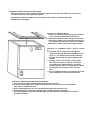
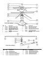
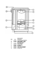
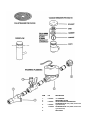
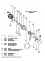
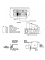
MODEL 24 B/BF
HIGH TEMPERATURE UNIT
NOVEMBER 1984
AFTER S/N 14389
BEFORE S/N 21800
INSTALLATION/OPERATION
and
SERVICE MANUAL
INCLUDES:
-Warranty Policy
-Installation Requirements
-Operating Instructions
-Basic Functions of Dishwasher
-Maintenance and Care
-Wiring Diagrams
-Description of Components
801 AIRPARK CENTER DRIVE
NASHVILLE, TN
(615)399-3944
1-800-736-8144
FAX(615)-366-9126
January 30,1998
7610-100-03-00 Rev A
MANUFACTURERS WARRANTY
ONE YEAR LIMITED PARTS & LABOR WARRANTY
ALL NEW JACKSON DISHWASHERS ARE WARRANTED TO THE ORIGINAL PURCHASER TO BE FREE FROM DEFECTS IN
MATERIAL OR WORKMANSHIP, UNDER NORMAL USE AND OPERATION FOR A PERIOD OF (1) ONE YEAR FROM THE DATE OF
PURCHASE, BUT IN NO EVENT TO EXCEED (18) EIGHTEEN MONTHS FROM THE DATE OF SHIPMENT FROM THE FACTORY.
Jackson MSC agrees under this warranty to repair or replace , at its discretion, any original part which fails under normal use due to faulty
material or workmanship during the warranty period, providing the equipment has been unaltered, and has been properly installed, main
tained and operated in accordance with the applicable factory instruction manual furnished with the machine and the failure is reported to the
authorized service agency within the warranty period. This includes the use of factory specified genuine replacement parts, purchased
directly from a Jackson authorized parts distributor or service agency. Use of generic replacement parts may create a hazard and void
warranty certification.
The labor to repair or replace such failed part will be paid by Jackson MSC, within the continental United States, Hawaii and Canada, during
the warranty period provided a Jackson MSC authorized service agency, or those having prior authorization from the factory, performs the
service. Any repair work by persons other than a Jackson MSC authorized service agency is the sole responsibility of the customer. Labor
coverage is limited to regular hourly rates, overtime premiums and emergency service charges will not be paid by Jackson MSC.
Accessory components not installed by the factory carry a (1) one year parts warranty only. Accessory components such as table limit
switches, pressure regulators, pre rinse units, etc. that are shipped with the unit and installed at the site are included. Labor to repair or
replace these components is not covered by Jackson MSC.
This warranty is void if failure is a direct result from shipping, handling, fire, water, accident, misuse, acts of god, attempted repair by unau
thonzed persons, improper installation, if serial number has been removed or altered, or if unit is used for purpose other than it was originally
intended.
TRAVEL LIMITATIONS
Jackson MSC limits warranty travel time to (2) two hours and mileage to (100) one hundred miles. Jackson MSC will not pay for travel time
and mileage that exceeds this, or any fees such as those for air or boat travel without prior authorization.
WARRANTY REGISTRATION CARD
The warranty registration card supplied with the machine must be returned to Jackson MSC within 30 days to validate the warranty.
REPLACEMENT PARTS WARRANTY
Jackson replacement parts are warranted for a period of 90 days from the date of installation or 180 days from the date of shipment from the
factory, which ever occurs first.
PRODUCT CHANGES AND UPDATES
Jackson MSC reserves the right to make changes in design and specification of any equipment as engineering or necessity requires.
THIS IS THE ENTIRE AND ONLY WARRANTY OF JACKSON MSC. JACKSON'S LIABILITY ON ANY CLAIM OF ANY KIND, INCLUD ING
NEGLIGENCE, WITH RESPECT TO THE GOODS OR SERVICES COVERED HEREUNDER, SHALL IN NO CASE EXCEED THE PRICE
OF THE GOODS OR SERVICES OR PART THEREOF WHICH GIVES RISE TO THE CLAIM.
THERE ARE NO WARRANTIES, EXPRESSED OR IMPLIED, INCLUDING FOR FITNESS OR MERCHANTABILITY, THAT ARE NOT SET
FORTH HEREIN, OR THAT EXTEND BEYOND THE DURATION HEREOF. UNDER NO CIRCUMSTANCES WILL JACKSON MSC BE
LIABLE FOR ANY LOSS OR DAMAGE, DIRECT OR CONSEQUENTIAL, OR FOR THE DAMAGES IN THE NATURE OF PENALTIES,
ARISING OUT OF THE USE OR INABILITY TO USE ANY OF ITS PRODUCTS.
ITEMS NOT COVERED
This warranty does not cover adjustments to timer cams or thermostats, cleaning wash arms or strainers, or replacement of wear items such
as curtains, squeeze tubes, drain balls, door guides, or gaskets beyond 30 days from installation of unit. Also not covered are conditions
caused by the use of incorrect (non commercial) grade detergents, excessive supply water temperature or pres sure, or hard water
conditions.
INDEX
SPECIFICATIONS
ELECTRICAL RATING
GENERAL INSTRUCTIONS (Installation)
GENERAL INSTRUCTIONS (Operation)
GENERAL INSTRUCTIONS Preventive Maintenance)
2
2
3
6
7
REMOVAL of RINSE and/or WASH HEAD ASSEMBLIES (General Instructions)
DEFECTIVE TIMER MOTOR
8
11
FUNCTION OF SWITCHES, CIRCUIT BREAKER and INDICATING LIGHTS
REPLACEMENT OF SWITCHES la FRONT DOOR INTERLOCK SYSTEM
CHECKOUT
THERMOSTAT ADJUSTMENT
RINSE TANK HEATER SYSTEM
WASH TANK HEATER SYSTEM
WATER LEVEL CONTROL
SERVICE INSTRUCTIONS
REPLACING SEAL AND CERAMIC for PUMP SYSTEM
TROUBLE SHOOTING GUIDE
PICTORIALS
FRONT VIEW
BACK VIEW
LEFT SIDE VIEW
RIGHT SIDE VIEW
PAN STRAINER, VACUUM BREAKER, OVERFLOW and INCOMING PLUMBING
RINSE TANK, WASH ASSEMBLY. WASH OR RINSE THERMOSTAT. WASH or RINSE
THERMOMETER
PUMP and MOTOR ASSEMBLY
SWITCHES. DOOR SAFETY SWITCH and SAFETY SWITCH
DRAIN VALVE CUTAWAY VIEW and PANEL
WIRING DIAGRAMS
PARTS LIST
PARTS DISTRIBUTORS
12
13
14
15
16
18
19
20
21
22
25
26
27
28
29
30
31
32
33
34
36
38
SPECIFICATIONS
JACKSON DISHWASHER MODEL 24 B - BP
OPERATING CAPACITY 100%
Racks per hour
Dishes per hour
248
21
525
Glasses per hour
525
OPERATING CYCLE
Wash Time — seconds
Rinse Time — seconds
120
15
Total Cycle — seconds
150
WASH TANK CAPACITY (Gallons)
5.65
RINSE TANK CAPACITY (Gallons)
3
WASH PUMP CAPACITY (GPM)
60
WATER REQUIREMENTS 100%
Inlet Temperature F
Gallons per hour
Row Pressure, PSI
Row, gallons per minute
Inlet size — IPS
140 deg.
52.3
20
7.1
1/2"
Drain size — 0.0.
1 1/2"
WASH PUMP MOTOR (HP)
1/2
WASH HEATER (kw)
1.0
RINSE HEATER (kw)
5.0
ELECTRICAL REQUIREMENTS (See below for details, under Electrical Rating)
DIMENSIONS
Height with Top
Height with no Top
Width
Clearance, Wall to Machine
Depth
Maximum Height for Dishes
36"
34 1/2 "
24"
2 1/4"
24"
14"
Rack Size
19 3/4"
NOTE VENTED BACK
•ALL "F" MODELS ARE FREE STANDING (Top and Side Panels)
ELECTRICAL RATING
MODEL
VOLTS
CYCLE
PHASE
APPROX.
TOTAL LOAD AMPS
24B
220
60
1
35
Refer to
248
208
60
1
35
Machine Data
248
208/220
50
1
28
Plate
Specifications subject to change without notice.
GENERAL INSTRUCTIONS
(INSTALLATION)
Note: Read the following instruction carefully. Proper Installation of your Jackson
Dishwasher will assure proper machine operation.
Uncrating 24:
1. Remove straps around carton.
2. Open top flaps of dishwasher carton.
3. Remove any packing from top and sides of machine that can be done with ease from top.
4. Slide carton sleeve upward over top of dishwasher, set to one side.
5. Lift dishwasher and wooden base from carton base.
6. Move dishwasher to general installation area.
7. Remove bolts holding wooden base to machine and screw In adjustable feet supplied.
8. Reassemble wash and rinse assemblies In machine using sketch and Instructions In this
manual.
9. Set dishwasher In place, ready for Installation.
Note: NSF base cradle Installation must be add Installed on all AF and BF models. Cradle goes
around bottom; secure la place using liquid adhesive.
Installation Instructions:
1. The dishwasher can be leveled to the proper height by adjusting the adjustable feet on the four
comers. The front of the unit should be 1/4" to 1/2" higher than the back.
2. Refer to the dimensional data sketch for connections.
3. The drain from the machine is a GRAVITY DRAIN SYSTEM and should, therefore, have the proper
drop from the machine to the kitchen's drain system. The drain connection is located to the left
rear of the machine when facing the machine's door. The drain fitting Is 1 1/2" 00 tube size, 7"
from floor.
4. IMPORTANT-PLEASE READ-Located on the back upper left comer of this unit Is a steam
equalizing vent. This vent in no way should be blocked off or prevented from allowing steam to
be vented to the outside of the unit or from under the cabinet In which the unit Is Installed.
Never pipe the steam downward toward the floor. (SEE PAGE 4 IF BEING INSTALLED UNDER A
COUNTER.)
5. The electrical connections should be made to the terminal board located at the left center front.
The terminals are marked LI. and NeutraL Install proper circuit breaker. wire and conduit size to
conform with local and/or national codes (standards).
Installation of Model 24 Top and Table gasket
These Instructions are to be used for applying the adhesive backed sponge rubber strip to the top of
the machine prior to setting the table in place.
Included with the Model 24 table is a 6 foot length of 1/4 " thick x 1" wide sponge rubber
adhesive backed stripping.
Instructions for applying gasket:
1. Place one end of the tripping along the complete
side of the tog support flange and cut It off.
2. Repeat the same procedure along the other side.
3. Place the remaining piece along the front edge, fit
It In between the aide pieces and cut It to length.
4. Remove the backing and set the strips in place.
Instructions for Installation under a porous counter
top:
1. If possible, a hole should be cut through the
counter top directly above the equalizing vent. A
piece of 1 1/4" OD pipe Is then Inserted through
the hole into the vent opening and piped to the
outside.
2. If cutting a hole In the counter Is not possible,
then a piece of stainless steel 36" wide by 36"
long bend In the middle at 90 deg. should be
centered directly over the vent to allow the steam
to condensate on It when It comes out of the
vent.
3. It Is very Important that this vent be kept open and
cool air allowed to circulate around the unit.
Installation of Model 24 Dishwasher Under Dishtable:
1. On the end of the table, locate bracket #4 opposite the sink end.
2. A square rubber gasket #3 Is supplied and should be secured to top frame of dishwasher
with caulk or suitable adhesive.
3. Place dishtable #2 where It Is to be Installed and support the machine's end.
4. Slide dishwasher #1 underneath dishtable #2 so that the outside of machine Is
positioned against the guide bracket #4. Make sure dishtable and dishwasher are In desired
permanent location.
5. Using the two holes In bracket #4 as a guide, drill two holes 9/64" diameter In the side panel
of machine. Note: Drill through first thickness of metal only.
6. Using the self-tapping screws supplied, screw them through bracket #4 and Into the side
panel of machine until screws are tight
Removal of Pan Strainer for Cleaning: (Wash and rinse head assemblies must be removed prior to
removing strainer.)
1. Turn heat switch 'off' and drain machine by depressing drain switch for approximately 50
seconds.
2. Remove wing nut from rinse feed pipe, remove rinse head assembly by pulling forward.
3. Remove wing nut from upper pump housing, wash head may now be lifted out.
4. Pan strainer now accessible, lift out and dean thoroughly.
5. Clean around pump Intake with bristle brush.
6. Replace stainer pan.
7. Re-Install wash and rinse head assemblies.
8. Clean strainer pan daily or as needed to insure proper machine operation.
Installation of Wash Head and Rinse Ann Assemblies: (Items disassembled for shipment)
1. Line holes up on wash head assembly to match slots In pump housing.
2. Insert wash head assembly down Into upper pump housing as far as
possible
3. Insert retaining pin to secure wash head to pump housing.
RINSE ARM ASSEMBLE
1. Line up stud to match with slot In nipple.
2. Insert rinse arm assembly into female
recepticle protruding through back of
machine.
3. Insert lanyard pin to secure rinse arm
assembly properly.
4. Make certain end plugs are secured property
In rinse tubes.
GENERAL INSTRUCTIONS
(OPERATION)
Note: Read the following instructions carefully. Proper operation of your Jackson
Dishwasher will assure clean and sanitized glasses and dishes, at optimum efficiency.
Dish Preparation:
1.
2.
3.
4.
Scrape dishes thoroughly.
Pre-wash dishes by soaking or with hose.
Place dishes and cups In dish rack, cups upside down.
Place glasses and silverware la combination glass-silverware rack. glasses upside down.
Scatter silverware loosely on bottom.
Note: Silverware In the upright position washes and rinses better than lying flat. These
silverware compartment racks an available through your dealer or Service Agency.
Operators Instructions:
1.
2.
3.
4.
5.
6.
7.
8.
Make sure dean pan strainer Is In place and slide empty rack In machine.
Place start rocker switch In center position.
Close door and lock latch.
Push top of fill switch and hold approximately 45 seconds.
Turn heater switch on.
Open door and slide rack of dishes Into dishwasher.
Dispense proper amount of detergent In machine.
Start automatic wash and rinse cycle of dishwasher by pushing on top or bottom of start
switch (with indicating light): light will come on.
9. When light goes out, cycle has ended, Open door, slide out rack of clean dishes to air dry,
slide In rack of dirty dishes, add detergent, close door and push start switch.
10. At end of mealtime, shut off by placing start rocker switch In center position and heater
switch off, Drain machine by pressing top of drain switch approximately 50 seconds,
Remove pan strainer after removing lower rinse arm and wash head assembly. clean inside
of machine and replace clean strainer, wash head and lower rinse arm assembly. (See page
on Installation of Wash Head and Rinse Arm Assemblies — Removal of Pan Strainer for
Cleaning.)
Detergent Recommendations and Rinse Additives:
We suggest that you contact your local Detergent Specialist for the correct detergent and rinse
additives tor your area. To help you until one can be reached, we suggest that you use a nonfoaming dishwasher detergent, approximately three tablespoons in wash tank when machine Is
filled and one teaspoon each cycle or load thereafter. This may have to be increased or
decreased to obtain satisfactory results.
GENERAL INSTRUCTIONS
(PREVENTIVE MAINTENANCE) (THE FOLLOWING IS TO BE
PERFORMED AS NEEDED.)
Note: Read the following Instructions carefully. Proper maintenance of your Jackcon
Dishwasher will ensure optimum service with a minimum of down time.
1. Remove all lime and corrosion deposits.
a. Fill the machine with wash water as would ordinarily be done for washing.
b. Open door and place one cup or less of de-liming compound Into the water. The
compound is available from your detergent supplier.
c. Turn on the manual wash switch and allow to wash for five minutes.
d. Open door and examine the interior. All lime should be removed and parts should
be shiny. If not, allow to wash for longer period.
e. After the Interior Is dean, with door closed, empty the wash water by depressing
drain switch for approximately 50 seconds. Refill machine and allow to run for two
minutes, then again drain the wash reservoir.
2. Clean around overflow strainers and drain hole.
a. Clean around overflow and strainer pan.
b. Clean around pump Intake (toothbrush makes excellent tool for cleaning).
3. Clean Y-strainer on Incoming water line. (Water to machine must be turned off for this
operation)
a. Remove plug and clean strainer.
4. Clean rinse tubes.
a. Remove rinse assembly by disconnecting rinse feed pipe and removing end plugs
on lower rinse.
b. Clean all rinse tubes and feed pipes with special brush supplied.
c. If spray holes in the rinse tubes are clogged, they may be cleaned with a pointed
object
5. Clean wash head assembly.
a. Loosen two wing nuts holding wash head assembly to pump.
b. Clean assembly at sink by flushing water through spray jets.
c. If spray jets are still plugged, use sharp object to dislodge and flush again.
d. Reinstall wash and rinse assemblies. (See page with Instructions.)
6. Clean any deposits which may have built up on exterior moving parts.
a. Clean around door gasket.
b. Using a soft bristle brush, clean around switches on exterior of control panel. (Use
no water.)
c. Use soft bristle brush, dip in wash tank water and scrub inside door around gasket
and hinges. Use clean cloth or paper towel to wipe off loose residue.
REMOVAL of RINSE and/or
WASH HEAD ASSEMBLIES
(GENERAL INSTRUCTIONS)
1. Before opening the door, hold the drain switch in and drain all of the water out of the
unit
2. Open the door and allow the unit a few minutes to cool off.
3. With your fingers, loosen the wing nut holding the rinse feed pipe. When it is loose, pull the
feed pipe out of the nipple and lay It to one side.
4. Locate Allen head set screw in the wash head cap, Insert Allen wrench and loosen screw by
turning counterclockwise.
5. Turn wash head cap counterclockwise until cap Is removed and put cap In safe place.
6. Remove 1/4" stainless ball bearings carefully and put it in a receptacle In a safe place.
7. Life and remove small manifold with short tubes. Put It In a safe place.
8. Remove 1/4" ball bearing In similar method to step 16.
9. Lift and remove large manifold with large length tubes similar to step #7.
10. The lower fixed race may be left in place.
11. Clean ball bearings by soaking in de-liming solution.
12. Ball bearing race ways may be cleaned by either brushing with de-liming solution
(toothbrush makes excellent tool) or gently clean by rubbing with fine sandpaper or emery
cloth.
13. Rinse ball bearings and manifolds thoroughly.
14. To reassemble, first fill lower race to capacity with 1/4" ball bearings, then remove one. This
will give proper movement needed during rotation of assembly.
15. Replace lower manifold and fill race fully with 1/4" ball bearings. Repeat, removing one only.
16. Replace upper manifolds and repeat necessary parts of step #14.
17. Replace wash cap by screwing on center shaft clockwise, finger tight.
18. Back off wash cap about 1/4 turn and tighten Allen set screw.
19. Rotate manifolds in opposite directions: see If they rotate freely. A rule of thumb Is to select
the longest tube in the bottom manifold and make sure It moves up and down at least V
and no more than 1/4".
20. Replace the rinse assembly and pipe by aligning the stud on the feed pipe with the slot in
the nipple. Push the feed pipe in gently as far as It will go and then secure It with the wing
nut.
21. Close the front door and refill dishwasher.
22. Run through several cycles and recheck wash arms for easy movement. Adjust if
necessary.
ITEM
1.
2.
3.
P/N
0186500
0187000
0194004
4.
0189000
5.
0189500
DESCRIPTION
WASH HEAD CAP WITH RACE
WASH HEAD CAP SET SCREW
WASH HEAD BEARING 1/4" S/S
WASH HEAD SMALL MANIFOLD
w/TUBES
WASH HEAD LARGE MANIFOLD
w/TUBES
ITEM
P/N
DESCRIPTION
6.
7.
0187500
0193600
WASH HEAD CENTER SHAFT
WASH HEAD FIXED RACE
8.
0188600
WASH HEAD SHAFT HOLDING PIN
9.
0109501
10.
0189805
UPPER PUMP HOUSING
WASH HEAD ASSEMBLY RETAINING
PIN w/RING
ITEM
P/N
DESCRIPTION
ITEM
P/N
DESCRIPTION
1.
2.
0125200
0126800
RINSE HEAD ARM
RINSE HEAD END PLUGS
3.
0126000
RINSE HEAD NYLATRON WASHER
5.
6.
7.
0126500
0137301
6137200
RINSE HEAD SNAP RINGS S/S
RINSE FEED PIPE LANYARD PIN
RINSE FEED PIPE (LOWER)
8.
0137202
RINSE FEED PIPE NIPPLE
4.
0125500
RINSE HEAD HEX BRUSHING S/S
TIMER for MODEL 24
DISHWASHERS
General Description
The timer is a self-contained (frame mounted) timer of the repeating cycle type. It is mounted on
the control panel of Jackson Automatic Dishwashing Machines, to control the automatic
functions of these -machines. It consists of a dock motor which operates on 60 cycle, AC,
110VAC or 50 cycle, AC, 220VAC. In addition to the dock motor, the timer also contains a driven
cam arrangement which operates three micro switches.
Principle of Operation:
The timer controls various operations of the automatic washers as per wiring diagram for each
machine; however, the timing cycle and the micro switches are the same for each model. The
time for One Complete Revolution of the cam shaft Is approximately 300 seconds, allowing two
wash and two rinse operations for each complete revolution of the cam shaft. The micro switch
nearest the timer motor is the hold circuit and uses both the NO and NC contacts. The middle
micro switch controls the wash and uses the NO contact. The micro switch farthest away from
the timer motor controls the rinse and uses just the NC contact
Service Instructions:
Caution: Always remove the power to the machine before working on the control panel or while
servicing the components on the switch panel. All electrical checks should be made by
qualified personnel.
Timer operation can be observed after removing the machine's kickplate by loosening the two
screws holding it.
If It is determined that the timer Is defective. It is recommended that a new timer be installed. If a
new timer is not available, limited field maintenance can be accomplished by changing the micro
switch.
A frozen contact on a micro switch will be indicated If one function of the timer Is being executed
all the time or If there Is an absence of a click when the switch arm is actuated.
To Replace Micro Switch:
1. Remove all wires from the timer, properly tag them to assure proper replacement.
2. Remove the two screws which hold the timer to the control panel.
3. One screw holds the micro switches, cams and actuating arms In the frame. This screw
is seen on the side opposite the motor. Remove this screw.
Note: Be sure to note which cam goes with which micro switch. Cam nearest timer motor has
½ of Its edge raised; center cam has 2 large depressed areas; cam furthest from timer
motor has two smaller depressed areas.
4. The unit can now be taken apart and the defective micro switch replaced.
5. Reassemble.
Note: The flanges on the cams are such that they only mesh in one direction.
The timer's cam drive system is equipped with a clutch to enable one to view the operations of
the cams and micro switches. Remove power to machine before touching timer. Rotate cams by
turning with fingers; cams will turn in one direction only. Do not force them. As cams actuate
switches, listen for the "click"" of the switch or test the switches with an ohmmeter.
DEFECTIVE TIMER MOTOR
A defective motor is indicated by the fact that the cams do not rotate or the machine does not
perform the automatic operations, or performs a specific part of the cycle continuously, but
works okay on manual. Remember, the timer motor is controlled by the start switch and the hold
micro switch; check this complete circuit before changing motor.
To Replace Motor:
1. Remove motor loads from shorting bar and neutral.
2. Remove the two screws which hold the motor.
3. Replace with a new motor.
Note: It may be necessary to remove complete timer to replace motor; If so, foilow steps 1 and
2, previous page.
TYPICAL TIMER SWITCH
P/N 1775
A . TO UPPER RIGHT TERMINAL START SWITCH
B . TO LOWER RIGHT TERMINAL START SWITCH
C . TO BOTTOM TERMINAL MANUAL WASH SWITCH
D . TO UPPER TERMINAL OF RINSE SWITCH
E. TO NEUTRAL TERMINAL
F. SHORTING BAR CONNECTED TO ALL THREE TIMER SWITCHES, THIS
TERMINAL
TIMER
P/N 0171700 (110V, 60 cycle)
P/N 0171800 (220V, 50 cycle)
MOTOR ONLY
FUNCTION of SWITCHES, CIRCUIT
BREAKER and INDICATING LIGHTS
Start switch:
P/N 0158800
This switch controls the timer motor through two circuits. (See electrical
diagram.) It is a three-position switch, up position = start: middle position = off;
down posi tion = start. To start, flip switch toggle in either up or down position;
Indicating light in center of panel will light verifying automatic cycle has started.
After cycle ends and you are ready to start a new cycle, flip toggle to opposite
position.
Cycle light
This light comes on only when automatic cycle is in progress and extinguishes
when cycle is complete. It is located In the start switch.
Manual wash
switch:
P/N 0155700
This switch is used to by-pass the timer and operate the wash pump manually.
The wash pump will run as long as this switch is "on". The prime purpose of this
switch is to extend the wash period for extremely soiled dishes before putting
them through the normal automatic cycle. It may also be used as an emergency
back-up should the timer ever fall to operate. The required wash time is Indicated
on the control panel (front).
Rinse/fill switchP/N 0154300
This switch is spring-loaded and must be held in its up position to operate. When
switch is operated, water Is allowed to fill machine through the rinse heads. It may
be used as an emergency back-up in case of timer failure for rinsing dishes. The
required rinse time is Indicated on the front control panel.
Heat switch:
P/N 0157800
This switch applies power to the heat circuits which are composed of automatic
control devices that turn heaters on and off to maintain required temperatures.
Heat light:
This indicating light remains lit all the time the heat switch is on. It is located in
the heat switch.
Drain switch:
P/N 0160900
This switch controls the manual draining of the unit at the end of a meal period or
at the end of the day. It is a spring-loaded switch and must be held in its up
position to operate. The switch when activated causes the drain valve to open and
the motor to go Into reverse, pumping the water out of the sump into the drain
line. This switch should be held for approximately 50 seconds.
REPLACEMENT of SWITCHES
in FRONT DOOR
There are fly switches installed in the front door. These are the start, drain, manual wash, rinse fill
and heater switches.
Before working on the machine. It is important that the power be turned off at the customer's
circuit breaker to prevent the possibility of electrical shock; trip the breaker to the "Off" position.
The five rocker switches are mounted in a rectangular hole held in position by a bracket. These
switches, are designed to be released from the inside and pushed outward. The spring sides must
be depressed to release the switch and bracket from the hole. To remove the bracket from the
switch, wedge a screwdriver In between them then lift up and move off.
If the switch to found to be defective, mount a new one into the bracket and Insert It Into the hole In
the control box. Make sure that the tab on the switch is in the proper notch on the bracket for easy
operation of the switch. Replace the wires from the used switch terminal by terminal on to the new
switch.
Power can now be applied to the dishwasher and run through cycles checking all
operations.
1. CONNECTION TERMINALS
2. BRACKET SPRING SIDES
3. PANEL PLATE
4. BRACKET FRONT
5. ROCKER BUTTON
INTERLOCK SYSTEM
The Interlock System is designed to prevent the machine from operating when the front door Is
opened or not latched property.
The Interlock System consists of two safety switches, one mounted so that the door latch has to be
closed to complete the circuit. The other switch is located so that a pin on the machine depresses a
safety switch mounted on the door, to complete the circuit. Either of these switches, if not
depressed, will prevent the machine from operating. Basically, the door must be closed and the door
latch locked in order for the machine to function.
CHECKOUT
(INTERLOCK SYSTEM)
Note: All eletrical checks should be made by qualified service personnel.
If it's determined that the proper power is being applied to the machine's incoming terminal
blocks, then further check of the safety switch should be made.
Note: This checkout would only be performed if none of the systems of the machine
operate. This would mean that none of the switches, when depressed, will perform
the function noted for that switch.
Example: Drain, fill, start or manual wash switches.
Proceed with checkout
1. Remove power to the machine by turning circuit breaker that protects the machine to "off"
position.
2. Open the front door and remove screws holding inside panel of door.
3. Disconnect one wire from the switch closest to the door latch and using an ohmmeter,
depress the lever of the switch and check that there is continuity across that switch. If
there is no continuity, replace switch.
4. Check second safety switch located in top lefthand comer of door. Remove wire from one
side of the switch and check for continuity with ohmmeter when switch is depressed. If
there is no continuity, replace switch.
5. Replace Inside door panel.
6. Re-apply power & re-check operation.
THERMOSTAT ADJUSTMENT
The thermostat can be adjusted by turning screw #1 (see picture) on the thermostat control box
cover. (Remember the present setting, in case the problems are elsewhere in the control circuit.) A
CW rotation is used to obtain a lower temperature setting and a CCW rotation is used to obtain a
higher temperature setting. A 1/4 turn of screw #1 changes the temperature approximately 15 °F. If
screw #1 is turned all the way to its top in either direction, adjust screw #2 as follows.
Note: Do not touch the screw sealed with red paint. When adjusting screw #2, power should be
disconnected during adjustment.
Set screw #1 so that it can be turned equal distances in either direction, then:
— If screw #1 stopped while turning in CW direction, turn screw #2 in CW direction, slowly and
only 1/4 of a turn or less per complete cycle of the unit.
— If screw #1 stopped while turning in CCW direction, turn screw #2 In CCW direction, slowly
and only 1/4 of a turn or less per complete cycle of the unit.
Three-fourths of a turn will bring the thermostat to approximately the same setting obtained when
screw #1 stopped. Check the present temperature setting before attempting any further
adjustments. Use screw #1 for any further adjustments.
Making large moves In adjusting may cause misalignment, thus increasing chances that further
adjustment cannot be made and thermostat will have to be replaced.
THERMOSTAT
PAST: P/N 1700
PRESENT:
P/N 0170018 - Rinse (Shown)
and 0170023 - Wash
RINSE TANK HEATER SYSTEM
Function:
The Rinse Tank Heater System is electrically connected in the circuit with the control system
functioning on 110/130V for 60 cycle and 220/240V (or 50 cycle system and the power system
functioning on 208/230V for both systems. The heat circuit is controlled by a heat switch
(mounted on coat door) and a thermostat (mounted near thermometer) which activates the coil
on the heat relay. When higher temperature is required, power is applied to the heaters when
the contacts of the heat relay are closed. Should the rinse tank thermometer read either too
high or too low, follow checkout below.
Checkout of Heater System for Rinse Tank: (Refer to drawing, Figure #2)
Note: The following checkout should be done by a qualified service person or electrician.
1.
2.
3.
4.
Turn off power to machine by tripping circuit breaker to "off" position.
Remove front kick plate below door.
Make sure rinse temperature is below 180°.
Reapply power and observe heat relay (2pole) letter E, figure 2, (next to timer) as heat
switch Is turned on and off several times.
1. If heat relay contacts do not close, with heat switch on:
a. Check power supply at Position 1 on terminal board X. Voltage should be 110VAC
on 60 cycle machine or 220VAC on 50 cycle machine (L1-L2).
b. Check Position 2; voltage should be 110V on 60 cycle machine or 220V on 50 cycle
machine. If not, check switch as necessary.
c. Check Position 3; there should be "zero" volts there. If not. read just thermostat per
thermostat Instructions.
d. If voltage is being applied to Positions 1 and 2, then the relay should be replaced;
coil on relay probably defective.
2. To determine If elements are working:
a. There's an Insulated movable bar on the heat relay across the top of the two
contacts. With an insulated probe, depress the bar and observe rinse thermometer:
the temperature should rise noticeably in a minute or two. If It moves very slowly. It
would indicate that one element Is defective. If It moves consistently higher at a
good rate, the elements are okay.
Note: A check with an amp probe. If available, can be made.
The elements together should draw 20 amps: one element will draw only 10 amps.
Replace element If found defective.
3. If the heat relay closes:
a. Check power supply at Position 4 on terminal board X, right hand view. It should be
220V approx. It not, check circuit breaker at customers panel: replace if defective.
b. Check power at Position 5; voltage should be 220V. If not, check connections and
wires for breaks: replace as necessary.
c. With heat switch on and relay closed, check power at Position 6: voltage should be
220V. If not, replace heat relay.
d. If No. 3 above checks out okay, check at Position 7: voltage should be 220V. If not,
check wiring from heat relay to elements for loose connections or-broken wires:
repair as necessary.
A . HEAT SWITCH
B . WATER LEVEL CONTROL
C . THERMOSTAT
D . (WASH) RING HEATER
E. RELAY
F. RINSE HEATERS
G. BUS BARS
X . TERMINAL BOARD
WASH TANK HEATER SYSTEM
Function:
The Wash Tank Heater Control system is electrically connected in the circuit to operate on
220V regardless whether system is 60 or 50 cycle. The heat circuit Is controlled by a heat
switch (mounted on front door), water level control (mounted middle of control panel), and
thermostat (mounted near thermometers). When higher temperature is required, power is
applied to the heater element through above controls. Should the wash tank thermometer read
either too high or too low, follow checkout below.
Checkout of Heater System for Wash Tank: (Refer to drawing. Figure 1.)
Note: The following checkout should be done by qualified service personnel or electrician.
1. Ready machine for normal dishwashing operation with wash tank water at proper level
2. Remove front kickplate below door.
Note: Power's still applied to circuit, so be careful.
3. Check power to machine at Position 1; terminal board X should read 110V on 60 cycle, or
220V. 50 cycle machine (L1-L2). If not, check customer's circuit breaker. If defective,
replace.
4. Wash temperature should be 130° or less to proceed.
5. Observe water level control, letter "B" (with front door closed and latched). Turn heat
switch on and off several times. Relay and contact points (Inside clear plastic case on
water level control) should move back and forth.
AA If water level control relay doesn't close, refer to page on Water Level Control's
function and checkout.
BB If water level control relay does close, proceed with heat switch on.
1. Check voltage at Position 1 on terminal board X. Voltage is 110 on 60 cycle machine or
220V on a 50 cycle machine (L1-L2).
2. Check Position 3, Figure 1: there should be no voltage. If there is voltage, then adjust
thermostat (refer to page on Thermostat Adjusting).
3. Check Position 2 at heat switch A. There should be 110V on 60 cycle. There should be
220V on 50 cycle.
4. Check Position 5. Figure 1, voltage should be 220. If not, check Position 8, there should
be 220V.
5. Temperature should rise slowly, a check with an amp probe would indicate If the
element Is drawing the correct amperage. Replace element if defective.
WATER LEVEL CONTROL
AS USED ON 24
P/N 0204500 (110V, 60 cycle)
P/N 0205000 (220V, 50 cycle)
Function:
The water level control device to utilized on this machine to automatically control the cutoff of
the wash tank heater when water drains from the wash tank.
Note: All electrical checks should be made by qualified service personnel.
The control is designed to sense when the proper water level is maintained. At this time, the
relay in the clear plastic case will activate, closing the circuit to the thermostat which
completes the wash tank heat circuit as it closes. If one of the following problems exist, this
unit should be checked out as shown below.
Symptoms of Level Control Failure:
1. Wash heater circuit Is not activated with water at proper level (up to overflow level on
overflow pipe) In wash tank.
2. Wash heaters remain on when water drained from wash tank. (Sometimes caused by
deposits on probe)
Proceed with Checkouts:
1. Remove power source to machine by moving circuit breaker to "off" position.
2. Remove screws holding lower kick plate on front of machine and locate water level control
(sketch below).
3. Remove, mark and Insulate, for easy replacement, wires going to letters C & H.
4. Re-apply power, turn on heat switch. With an insulated wire. connect Jumper wire between
terminals C & H (24 volt system).
5. If relay operates, (he water level control action can be deemed operational; then other
causes should be explored.
6. If relay doesn't operate, replace control.
7. Remove power source once again and replace wires that were removed in step three to
original terminals (see trouble shooting section for other possible causes).
SERVICE INSTRUCTIONS
(INCOMING WATER SOLENOID VALVE)
P/N 0143500 (60 cycle)
P/N 0144000 (50 cycle)
SOLENOID VALVE
P/N 0142000 (110V, used on 60 cycle machine)
P/N 0142500 (220V, used on 50 cycle machine)
To take the valve apart
Disassembly — These valves may be taken apart by
unscrewing the bonnet and the enclosing tube
assembly from the valve body assembly. See Fig. 3.
After unscrewing, carefully lift off the bonnet and
enclosing tube assembly. Don't drop the plunger. The
"O" ring seal and diaphragm cartridge can now be
lifted out.
Be careful not to damage the machined faces while
the valve is apart
To Reassemble — Place the diaphragm cartridge in
the body with the pilot port detention UP. Hold the
plunger with the synthetic seat against the pilot port.
Make sure the "O" ring is in place, then lower the
bonnet and enclosing tube assembly over the
plunger. Screw bonnet assembly snugly down on the
body assembly.
DIAPHRAGM CARTRIDGE
Possible Problems
Pilot Port extension #1 clogged
Hole #2 clogged
Remedy
Pass heated straight pin through hole #2
or clean hole #1
SEAL and CERAMIC for
PUMP SYSTEM
(GENERAL INFORMATION)
The wash and drain pump are part of the total motor pump system. One seal and ceramic are
utilized to prevent the pump from leaking.
Replacement of Seal and/or Ceramic:
1.
2.
3.
4.
5.
6.
7.
8.
9.
10.
11.
12.
13.
14.
15.
16.
17.
18.
19.
Drain machine either by depressing drain switch or by balling out
Turn Incoming power to machine off.
Open door — remove dolly, racks, rinse head assembly and wash head assembly.
Remove kickplate (located under front door).
Unplug motor at connector
Loosen eight screws holding pump in sump tank.
Disconnect drain hose from motor (must be done from underneath machine).
Pull motor and pump gently upward and move from side to side as required to remove unit.
(Old machine motor removed downward.)
Set pump and motor on bench and proceed.
Loosen eight screws holding upper pump housing, and remove housing.
Remove diffuser plate.
Loosen Impeller screw and remove Impeller.
Remove suction adapter plate.
Remove drain Inlet plate.
Remove propeller.
Remove mounting plate from motor (loosen 4 phillips head screws on bottom of plate).
Knock out old seal carefully and clean hole, re-insert new seal.
Note: Be sure not to ruffle edges of seal when inserting. Seal should contact all
resting surfaces at one time.
Ceramic is imbedded In propeller and normally does not wear or need replacement but
check for cracks.
Re-install motor and pump by reversing above process.
1. MOTOR
2. MOUNTING PLATE
3. STATIONARY SEAL
4. SHIM WASHERS
ON MOTOR SHAFT
5. CERAMIC
6. DRAIN PROPELLER
TROUBLE SHOOTING GUIDE
PROBLEM
Water overflow out bottom of front door
when wash pump Is operating.
Wash motor doesn't operate on manual
wash.
CAUSE
Machine not level
Overflow drain clogged.
SOLUTION
Level machine.
Slight tilt to rear
Remove obstruction, checking
Inside of machine fIrst
Water level in machine's wash reservoir
too high.
Solenoid valve not closing at end of
fill or rinse cycle causing excessive
water problem.
Detergent foaming.
Equalizing vent blocked.
Wires broken or loose.
Reduce quantity of detergent
Allow free steam flow.
Check all wires In the motor a
reconnect as necessary.
Defective manual wash switch.
Replace.
Bad bearing, noticeable by noisy bearings
or locked drive shaft.
Replace.
Defective motor starting relay. (Typical •
motor hums.)
Replace.
Note: The motor starting relay Is utilized to insert a starting field In the wash pump motor, once the motor has gained
speed, the running winding will then take over and the starting winding will be removed when the relay kicks out.
This relay Is the amperage sensing type.
Motor runs on manual wash but doesn't
operate on automatic (rinse operates
okay on both manual and automatic
cycles.)
Defective center micro switch of
timer.
Defective circuit in manual wash
switch.
No water comes through the rinse arms
when the rinse fill switch is depressed.
Hand water valve to machine not turned
on.
Turn on water valve.
Defective coil on solenoid valve.
Replace coil.
Broken or loose wires.
Repair or reconnect.
Defective manual rinse (ill switch.
Replace.
Limed up rinse heads or piping.
Begin-by cleaning rinse head using
instructions (or de-lime If this isn't
satisfactory, there clean the rinse
feed pipes.
Water pressure low.
Increase pipe size to machine
Little or no water coming through rinse
assemblies.
Replace switch.
Replace switch.
TROUBLE SHOOTING GUIDE
PROBLEM
CAUSE
Rinse doesn't operate on automatic
during timed cycle (but does operate
on manual rinse/fill operation).
Micro switch defective (this is the micro
switch furthest from the timer motor on the Replace.
timer assembly).
Rinse water runs continuously with
circuit breaker controlling machine
turned off.
SOLUTION
Rinse fill switch defective on N.C. contacts,
Replace.
Defective plunger in solenoid valve.
Replace plunger.
Defective diaphragm in solenoid valve.
Check both holes in diaphragm cartridge
to Insure that they are open, The one on
the outside perimeter should be the size
of an ordinary straight pin. If it's not,
heat a straight pin and put It through this
hole to enlarge. If this falls to correct
situation, replace diaphragm.
Note: In disassembling solenoid valve, use instructions shown on separate page.
Rinse water runs continuously with
power applied to machine, but when
circuit breaker to machine is turned off,
water stops.
Defective rinse/fill switch.
Defective timer that has
stopped in a position
keeping the rinse on.
Defective micro switch on timer assembly.
Replace.
Replace timer motor or
timer as necessary
Replace.
Note: Excessive water line pressure can cause water to continually run even though the power to the machine is turned off.
Check specifications for required pressure.
Wash temperature not at required
reading on thermometer.
Defective thermometer.
Rinse temperature not at required
temperature, causing wash
temperature to be lowered during
rinse cycle.
Using a thermometer (fast reading type
that's known to be correct). Insert in
wash rerservoir and check reading
against wash thermometer on machine.
If machine thermometer isn't correct
within three or four degrees, replace.
Check out rinse heat using heater
checkout system page in manual.
Note: Any switches, water level controls, heater elements, relays or contactor that have to be checked out, can be
done using the heater checkout system page.
TROUBLE SHOOTING GUIDE
PROBLEM
Rinse water not at required
temperature range.
CAUSE
SOLUTION
Heater switch defective.
Replace.
Water level protection control defective.
Replace.
Heater element defective.
Replace.
Wires loose or burned off.
Retighten or Replace.
Thermometer's defective.
Replace.
Heater switch defective.
See page on heater system
checkout
Thermostat defective.
Adjust using instructions on
thermostat page and heater
system's checkout page. Replace if
necessary.
Defective heater relay on contactor.
If defective, replace. See note on
heater system above.
After filling machine with water,
leakage began at lower front panel
Overflow drain clogged.
without machine operating or at end of
rinse cycle.
Machine doesn't drain when drain
switch is depressed.
Clean away obstruction.
Drain solenoid dogged.
Defective switch.
Remove obstruction.
Replace.
Defective motor or motor start relay.
Replace.
Defective drain solenoid.
Replace.
Note: The drain pump of this machine is part of wash motor, so if wash motor operates property drain system should
work.
ITEM
1.
2.
3.
4.
4A.
5.
6.
7.
8.
8.
9.
10.
11.
12.
13.
14.
P/N
0051200
486
0125100
0125200
0188900
0005700
0060200
0142500
0142000
0185000
0153600
0030500
0170018
0170023
0169100
FRONT VIEW
DESCRIPTION
DOOR HANDLE ASSEMBLY
SWITCHES
FRONT DOOR (NLA)
RINSE ASSEMBLY, UPPER
RINSE ASSEMBLY, LOWER
WASH ASSEMBLY
BOOSTER TANK
HEATER ELEMENTS
SOLENOID (220V, used on 50 cycle machines)
SOLENOID (110V, used on 60 cycle machines)
VALVE FOR HEALTH INSPECTOR GAUGE
"Y" STRAINER
ELECTRIC PANEL
INCOMING WATER CONNECTION
RINSE THERMOSTAT
WASH THERMOSTAT
THERMOMETERS
ITEM
1.
2.
2.
3.
4.
5.
6.
P/N
0184101
0108100
0108200
0005700
0185900
BACK VIEW
DESCRIPTION
VACUUM BREAKER ASSEMBLY
PUMP & MOTOR ASSEMBLY (110V, 60 cycle)
PUMP & MOTOR ASSEMBLY (220V, 50 cycle)
DRAIN—GRAVITY FEED
BOOSTER TANK
EQUALIZING VENT
INCOMING WATER CONNECTION
ITEM
1.
2.
3.
4.
5.
6.
7.
7.
8.
9.
9.
10.
P/N
0184101
0051200
0048700
0054900
0083400
0108100
0108200
0142400
0142200
LEFT SIDE VIEW
DESCRIPTION
VACUUM BREAKER ASSEMBLY
DOOR HANDLE ASSEMBLY
FRONT DOOR, OUTER
KICK PANEL
INCOMING WATER CONNECTION
ADJUSTING FEET
PUMP & MOTOR ASSEMBLY (110V, 60 cycle)
PUMP & MOTOR ASSEMBLY (220V, 50 cycle)
DRAIN—GRAVITY FEED
DRAIN SOLENOID VALVE (110V, used on 60 cycle machine)
DRAIN SOLENOID VALVE (220V, used on 50 cycle machine)
SIDE FRAME & BRACE
ITEM
1.
2.
2A.
3.
4.
5.
6.
7.
8.
9.
10.
P/N
0184101
0125100
0125200
0188900
0005700
0083400
0054900
0048700
0051200
0054700
RIGHT SIDE VIEW
DESCRIPTION
VACUUM BREAKER ASSEMBLY
RINSE ASSEMBLY, UPPER
RINSE ASSEMBLY, LOWER
SIDE FRAME & BRACE
WASH ASSEMBLY
BOOSTER TANK
ADJUSTING FEET
KICK PANEL
FRONT DOOR OUTER ONLY
DOOR HANDLE ASSEMBLY
OPTIONAL TOP
ITEM
P/N
DESCRIPTION
1.
2.
3.
0153600
4.
0142000
"Y" STRAINER
REMOVABLE FILTER
VALVE FOR HEALTH INSPECTOR
SOLENOID VALVE 1/2" (110V, used on 60
cycle machine)
SOLENOID VALVE 1/2" (220V, used on 50
cycle machine)
PIPE UNION
4.
5.
0185000
0142500
ITEM
1.
2.
3.
4.
5.
6.
7.
8.
ITEM
1.
2.
3.
4.
5.
P/N
0056900
0125200
0188900
DESCRIPTION
WASH TANK RING ELEMENT
RINSE ASSEMBLY, LOWER
WASH ASSEMBLY
WASH RESERVOIR
HOLES FOR WASH TANK
ELEMENT
P/N
0005700
0058900
0060200
DESCRIPTION
BOOSTER TANK
BUS BAR
BOOSTER HEATER ELEMENT
THERMOSTAT COUPLING
HEATER COUPLINGS
WATER INLET
THERMOMETER COUPLING
WATER OUTLET
ITEM
1.
2.
3.
4.
5.
6.
7.
8.
9.
10.
P/N
0108100
0108501
0108501
0109001
0108501
0108501
0109501
0109501
0109501
0108501
DESCRIPTION
MOTOR AND PUMP ASSEMBLY
MOUNTING PLATE
STATIONARY SEAL ASSEMBLY
SHIM WASHERS
ROTATING CERAMIC
PROPELLER FOR DRAIN PUMP
"O" RING SEAL
DRAIN INLET PLATE
SUCTION ADAPTER PLATE
IMPELLER FOR WASH PUMP
(also 0109000-IMP only)
11.
0109501
TRUSS HEAD SCREW
12.
0109501
DIFFUSER (ALSO 1087)
13.
0109501
UPPER PUMP HOUSING (ALSO 1096)
13A.
0108400
GASKET
14.
0193600
WASH HEAD BOTTOM ADAPTER AND FIX RACE
15.
0109700
FILL HEAD MACHINE SCREW (SHORT)
16.
0109800
FILL HEAD MACHINE SCREW (LONG)
17.
0189700
WING NUT
18.
0188600
WASH HEAD SHAFT HOLDING PIN
19.
0108602
SEALING WASHERS
20.
0108400
PUMP GASKET
21.
0108601
MOUNTING CLIPS
NOT SHOWN 0108600 PUMP TINNERMAN KIT (INCLUDES START
AND ITEM NUMBERS 14,15, 16,17, 18 (COMES WITH 0108100
SWITCHES
ITEM
P/N
DESCRIPTION
1.
2.
3.
4.
5.
0158800
0154300
0157800
0155700
0160901
START—SPDT (lighted)
RINSE FILL—SPDT (momentary)
HEATER— DPST (lighted)
MANUAL WASH-SPST
DRAIN DPDT (momentary) 6-TERM.
5A.
0160900
DRAIN TPDT (momentary) 9-TERM.
ITEM
P/N
PANEL DESCRIPTION
1.
2.
2A.
3.
4.
4.
5.
5.
6.
6.
7.
7.
8.
9.
0169100
0170018
0170023
0165600
0120701
0120900
0204500
0205000
0121000
0120900
0171700
0171800
THERMOMETERS, WASH & RINSE
THERMOSTAT, RINSE
THERMOSTAT, WASH
TERMINAL BOARD, INCOMING ELECTRICAL CONNECTION
STARTING RELAY (110V, for 60 cycle machine)
STARTING RELAY (220V, for 50 cycle machine)
WATER LEVEL CONTROL (110V, for 60 cycle machine)
WATER LEVEL CONTROL (220V, for 50 cycle machine)
HEATER RELAY (110V, for 60 cycle machine)
HEATER RELAY (220V, for 50 cycle machine)
TIMER (110V, for 60 cycle machine)
TIMER (220V. for 50 cycle machine) MOTOR ONLY
GROUND LUG
MOTOR RELAY
0121300
COMPLETE PARTS LIST FOR MODEL 24
0005700
0030500
0047200
0047300
0047400
0051200
0051300
0044700
0052300
0052400
0053400
0053500
0053600
0054400
0054500
0054600
0054700
0056900
0058900
0060200
0060700
0084300
0108100
0108200
0108400
0108501
0108700
0109000
0109501
0109600
0109700
0109800
0110200
1003600
1003500
0120500
0120701
0120900
0121000
0121300
0125100
0125200
0126800
0125500
0125700
0126000
0126500
0130100
0134000
6137200
0137202
0137301
0138700
Booster Tank (stripped) for 24B
Control Panel, wired (lower front) for 24B (specify 50 or 60 cycle machine)
Door, complete, stripped (obsolete)
Door, front, outer only, stripped (obsolete)
Door insert, inner only, stripped
Door Handle Assembly
Door Handle Cam
Door Handle Cam Nut
Door Gasket
Door Gasket, Clamp Assembly
Drain Hose-Pump to Solenoid Valve, Short
Drain Hose Clamps
Drain Hose-Solenoid Valve to Drain, long
Door Spring
Enclosure Panel, righthand side
Enclosure Panel, lefthand side
Enclosure Panel, top
Heater Element, ring-style, 1000W, 220V
Heater Bus Bar, 2-hole, copper
Heater Element, short, 220V. 2500W
Heater Element, short, 208V, 2500W
Probe, Lundy, small
Pump Assembly, complete with motor, 115V, 60 cycle
Pump Assembly, complete with motor, 220V, 50 cycle
Pump Gasket
Pump Propeller Mounting Plate and Seal Assembly, kit
Pump Diffuser (only) NLA use 0109501 Kit
Pump Impeller, kit
Pump, Upper Housing, kit
Pump, Upper Housing, (only) NLA use 0109501 kit
Pump Pill Head Machine Screws, short
Pump Fill Head Machine Screws, long
Rack Trolley, movable, s/s (obsolete)
Rack, square, 19 3/4 x 10 3/4" (cup, bowl, glass)
Rack, square, 19 3/4 x 19 3/4" (dish-molded)
Relay, 110V, 2-pole, HW Heat Circuit
Relay, 110V, Motor Starting
Relay, 220V, Motor Starting, (for 50 cycle machine)
Relay, 220V, 2-pole. HW Heater Circuit, (for 50 cycle)
Relay Motor
Rinse Head Assembly, upper
Rinse Head Assembly, lower
Rinse Head End Plug
Rinse Head, Hex Bushing
Rinse Head, upper. Dual Systems (obsolete)
Rinse Head, Nylatron Washer
Rinse Head, Snap Ring,sis
Lower Feed Pipe Knurled Holding Screw
Rinse Head Brush, Tube Cleaning
Rinse Head Feed Pipe, lower
Rinse Feed Pipe Nipple
Rinse Feed Pipe Lanyard Pin
Rinse Head Spray Nozzle, Dual System
1
1
1
1
1
1
1
2
1
1
1
4
1
2
1
1
1
1
2
2
2
1
1
1
1
1
1
1
1
1
4
4
1
1
2
1
1
1
1
1
1
1
2
2
2
2
2
1
1
1
1
1
6
COMPLETE PARTS LIST FOR MODEL 24
0142000
0142200
6142300
0142400
0142500
0143500
0144000
0145000
0147500
0148500
0149500
0153100
0154300
0155700
0157800
0158800
0160901
0160900
6161000
0164100
0164300
0164700
0165600
0169100
0170018
0170023
0171700
0171800
0172200
0177500
0184101
0 184600
0186500
0187000
0187500
0188600
0188900
0189000
0189500
0199505
0189805
0193600
0194004
0204500
0205000
Solnoid Valve, 1/2",JE 110V
Drain Valve, Dole 1/2220V, (for 50 cycle machine)
Drain Valve Kit, Includes Valve, Bracket, Hoses
Drain Valve, Dole 1/2 110V, (Valve only)
Solenoid Valve, 1/2" JE, 220V, (for 50 cycle machine)
Solenoid Valve Coil. 110V, JE
Solenoid Valve Coil, 220V, JE (for 50 cycle machine)
Solenoid Valve Diaphragm Cartidge & "0" Ring, JE
Solenoid Valve "0" Ring.JE
Solenoid Valve, Plunger Assembly, JE
Solenoid Valve, Strainer Screen, JE
Strainer, Pan-Type
Switch, Rinse-Fill (Rocker-type)
Switch, Manual Wash (Rocker-type)
Switch, Heat (Illuminated rocker-type)
Switch, Start (Illuminated rocker-type)
Switch, Drain (Rocker-type), 9 Term.
Switch, Drain, 6 Term.
Switches wired w/harness
Switch interlock (side or latch)
Switch Bracket, for side interlock, use 6051500
Switch Bracket, for latch interlock
Terminal Board,3-pole
Thermometer, 36" Cap., Rinse
Thermostat, Rinse, 180 deg., fixed
Thermostat, Wash 150°, fixed
Timer, 115V w/wires, 60 cycles
Timer, 220V w/wires, 50 cycles, Motor Only
Timer Motor, 115V, for Module-Type Timer
Timer Micro Switches, Plastic Module-Type
Vacuum Breaker, Sloan, 1/2
Vacuum Breaker, Sloan, Float and Seal Repair Kit
Wash Head Cap w/Race
Wash Head Cap Set Screw
Wash Head Center Shaft
Wash Head Holding Pin
Wash Head Assembly, complete
Small Manifold w/Tubes, Wash Head
Large Manifold w/Tubes, Wash Head
Wash Head Knurled Screw
Wash Head Assembly Retaining Pin w/Ring
Wash Head Fixed Race
Wash Head Bearings, 1/4" s/s, Pkg of 25
Water Level Control, 110V, Curtis
Water Level Control, 220V, Curtis (for 50 cycle)
1
1
1
1
1
1
1
1
1
1
1
1
1
1
1
1
1
1
1
1
1
1
1
1
1
1
1
1
1
3
1
1
1
1
1
1
1
1
1
2
1
2
57
1
1