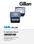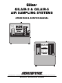
1
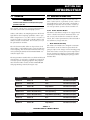
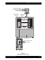
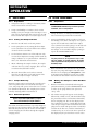
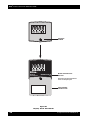
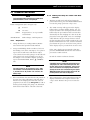
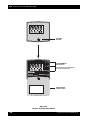
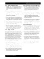
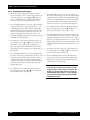
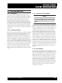
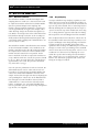
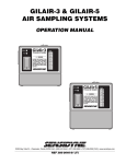
Gilian®
GILAIR-3 & GILAIR-5
AIR SAMPLING SYSTEMS
OPERATION & SERVICE MANUAL
Battery
Fault
G L
A
R
Personal Air Sampler
by
®
Gilian
WARNING
Substitution of components
may impair intrinsic safety.
Use only with Gilian battery
pack PN 800464 or 800464-1.
4
Flow
3
2
RFI
1
Made in USA
Battery
Fault
GilA ir5
Tri-Mode Air Sampler
5
4
WARNING
Substitution of components may
impair intrinsic safety. Use only
specified GilAir5 battery packs.
See Labeling for intrinsic safety
approvals.
Pat. Pending
Flow
Made In USA
®
Gilian
3
2
1
RFI
16333 Bay Vista Dr. • Clearwater, Florida 33760 • (800) 451-9444 • (727) 530-3602 • (727) 539-0550 [FAX] • www.sensidyne.com
Revision E • Document No. 800880M
Gilian® GILAIR-3 & GILAIR-5 AIR SAMPLING SYSTEMS
PACKING LIST
The items listed below are shipped the Gilian GilAir-3/GilAir-5 Air Sampling System:
•
GilAir-3 or GilAir-5 Air Sampling Pump
•
Tool Kit
•
Tubing
•
Air Boss
•
Restrictor
•
Operation and Service Manual
•
Registration Card/Warranty Card
ALWAYS check to make certain
you have received all of the items listed above.
If you have any questions or need assistance,
contact your Gilian Sales Representative, or call
(800) 451-9444
OR
(727) 530-3602
Sensidyne Document No. 800880M (Rev E)
3
Gilian® GILAIR-3 & GILAIR-5 AIR SAMPLING SYSTEMS
PROPRIETARY NOTICE
This manual was prepared exclusively for the owner of the Sensidyne GilAir Air Sampling System. The material within this
manual is proprietary information and is to be used only to understand, operate, and service the instrument. By receiving
this document, the recipient agrees that neither this document nor the information disclosed within nor any part thereof
shall be reproduced or transferred, physically, electronically or in any other form, or used or disclosed to others for manufacturing or for any other purpose except as specifically authorized in writing by Sensidyne, Inc.
COPYRIGHT NOTICE
© 2001 Sensidyne, Inc. All Rights Reserved. No part of this document may be reproduced, transmitted, transcribed, stored
in a retrieval system, or translated into any language in any form by any means without the prior written permission of
Sensidyne, Inc..
TRADEMARK NOTICE
Sensidyne, the Sensidyne logo, Gilian, and the Gilian logo are registered trademarks. These trademarks are protected through
use and registration in the United States. The trademarks and servicemarks used in this document are the property of their
respective companies and are used only for informational and explanatory purposes.
DISCLAIMER
THE SELLER ASSUMES NO RESPONSIBILITY WHATSOEVER, TO ANY PARTY WHOSOEVER, FOR ANY
PROPERTY DAMAGE, PERSONAL INJURY, OR DEATH RECEIVED BY OR RESULTING FROM, IN
WHOLE, OR IN PART, THE IMPROPER USE, INSTALLATION, OR STORAGE OF THIS PRODUCT BY THE
USER, PERSON, FIRM, ENTITY, CORPORATION OR PARTY NOT ADHERING TO THE INSTRUCTIONS
AND WARNINGS IN THIS MANUAL, OR OTHERWISE PROVIDED BY THE SELLER OR FROM NOT ADHERING TO ALL FEDERAL, STATE, AND LOCAL ENVIRONMENTAL AND OCCUPATIONAL HEALTH AND
SAFETY LAWS AND REGULATIONS.
THE SELLER SHALL NOT BE LIABLE FOR DIRECT, INDIRECT, CONSEQUENTIAL, INCIDENTAL OR
OTHER DAMAGES RESULTING FROM THE SALE AND USE OF ANY GOODS AND SELLERS’ LIABILITY
HEREUNDER SHALL BE LIMITED TO REPAIR OR REPLACEMENT OF ANY GOODS FOUND DEFECTIVE.
THIS WARRANTY IS IN LIEU OF ALL OTHER WARRANTIES, EXPRESSED OR IMPLIED, INCLUDING BUT
NOT LIMITED TO THE IMPLIED WARRANTIES OF MERCHANTABILITY AND FITNESS FOR USE OR FOR
A PARTICULAR PURPOSE WHICH ARE EXPRESSLY DISCLAIMED.
4
— PRELIMINARY —
Sensidyne Document No. 800880M (Rev E)
Gilian® GILAIR-3 & GILAIR-5 AIR SAMPLING SYSTEMS
TABLE OF
CONTENTS
• PREFACE
• Notices ...................................................................................................................................3
• Packing List .......................................................................................................................... 4
• WARNINGS ........................................................................................................................... 8
SECTION ONE: INTRODUCTION
1.1
Overview ..................................................................................................................... 9
1.2
General Description .................................................................................................. 9
1.2.1
1.2.2
1.3
Basic Control Board .........................................................................................9
Internal/External Vent Control ...................................................................... 10
Display Icons & Messages ....................................................................................... 11
SECTION TWO: OPERATION
2.1
Basic Model ................................................................................................................14
2.1.1
2.1.2
2.1.3
2.1.4
2.2
Clock Timer Model ...................................................................................................14
2.2.1
2.2.2
2.2.3
2.2.4
2.2.5
2.2.6
2.2.7
2.3
Preparation..................................................................................................... 14
Setting The Pump Flow Rate ......................................................................... 14
Sample Gathering ..........................................................................................14
Pull Start Operation ....................................................................................... 14
Preparation..................................................................................................... 14
Waking the Pump For “LAST” Run Data Readout ......................................... 14
Setting The Pump Flow Rate ......................................................................... 15
Sample Gathering ..........................................................................................15
HOLD (Pause) Feature .................................................................................. 15
Sampling Run Termination & Recovery ........................................................ 15
Display Self-Test ............................................................................................ 15
Program Timer Model .............................................................................................17
2.3.1
2.3.2
2.3.3
2.3.4
2.3.5
2.3.6
2.3.7
2.3.8
Preparation..................................................................................................... 17
Waking the Pump For “LAST” Run Data Readout ......................................... 17
Setting The Pump Flow Rate ......................................................................... 19
Sample Gathering ..........................................................................................19
HOLD (Pause) Feature .................................................................................. 19
Sampling Run Termination & Recovery ........................................................ 19
Display Self-Test ............................................................................................ 19
Programming The Pump ............................................................................... 20
Sensidyne Document No. 800880M (Rev E)
5
Gilian® GILAIR-3 & GILAIR-5 AIR SAMPLING SYSTEMS
TABLE OF
CONTENTS
SECTION THREE: FLOW OPERATION
3.1
Low Flow Operation ................................................................................................21
3.1.1
3.1.2
3.1.3
3.1.4
3.2
Description..................................................................................................... 21
Constant Low Flow ........................................................................................ 21
Constant Low Flow Module........................................................................... 21
Bag Sampling ................................................................................................. 21
Multi-Flow Operation .............................................................................................. 22
3.2.1
3.2.2
Multi-Flow Module ........................................................................................ 22
Bag Sampling ................................................................................................. 22
SECTION FOUR: BATTERY SERVICE
4.1
Service Overview ......................................................................................................23
4.1.1
4.1.2
4.1.3
4.2
Charging Systems ..................................................................................................... 24
4.2.1
4.2.2
4.2.3
6
Battery Life ..................................................................................................... 23
Memory Effect ................................................................................................23
Leakage Current .............................................................................................23
Single Station Charger.................................................................................... 24
Universal Multi-Station Charger..................................................................... 24
BMS Multi-Station charger ............................................................................. 24
— PRELIMINARY —
Sensidyne Document No. 800880M (Rev E)
Gilian® GILAIR-3 & GILAIR-5 AIR SAMPLING SYSTEMS
TABLE OF
CONTENTS
SECTION FIVE: APPENDICES
•
Appendix A: Parts List ............................................................................................ 25
•
Appendix B: Specifications ................................................................................... 26
•
Appendix C: Troubleshooting Guide ................................................................... 27
•
Appendix D: Returned Material Authorization ................................................. 28
•
•
Returned Material Authorization ................................................................... 28
Service Options .............................................................................................. 28
LIST OF FIGURES
1.1
1.2
2.1
2.2
GilAir-3 Air Sampler (Front View) ........................................................................... 12
GilAir-5 Air Sampler (Front View) ........................................................................... 13
Display: Clock Timer Model ................................................................................... 16
Display: Program Timer Model ............................................................................... 18
LIST OF TABLES
1.1
1.2
4.1
Available GilAir-3 & GilAir-5 Models ........................................................................ 9
Pneumatic System .................................................................................................... 10
Estimated Battery Life .............................................................................................. 23
Sensidyne Document No. 800880M (Rev E)
7
Gilian® GILAIR-3 & GILAIR-5 AIR SAMPLING SYSTEMS
WARNINGS !
READ AND UNDERSTAND ALL WARNINGS BEFORE USE
WARNING: Do not use the BMS-200 Battery Charger to charge SIRA approved battery packs.
Read and understand ALL warnings before using this product. Failure to read, understand, and comply with
ALL warnings could result in property damage, severe personal injury, or death.
Read and understand ALL applicable Federal, State, and Local environmental health and safety laws and
regulations, including OSHA. Ensure complete compliance with ALL applicable laws and regulations before
and during use of this product.
UNDER NO CIRCUMSTANCES should this product be used except by qualified, trained, technically
competent personnel and not until the warnings, Operation and Service Manual, labels, and other literature
accompanying this product have been read and understood.
The Operation and Service Manual must be read and understood by each user before operating this product
or using its accessories, in order to ensure proper and safe use and installation of this product and to ensure
familiarity with the proper treatment and safety procedures in the event of an accident.
DO NOT remove, cover, or alter any label or tag on this product, its accessories, or related products.
DO NOT operate this product should it malfunction or require repair. Operation of a malfunctioning product,
or a product requiring repair may result in serious personal injury or death. DO NOT attempt to repair or
modify the instrument, except as specified in the Operation and Service Manual. Contact the Gilian Service
Department to arrange for a Returned Material Authorization (RMA).
Use ONLY genuine Gilian® replacement parts when performing any maintenance procedures described in
this manual. Failure to do so may seriously impair instrument performance. Repair or alteration of the product
beyond the scope of these maintenance instructions, or by anyone other than a certified Gilian® serviceman,
could cause the product to fail to perform as designed and persons who rely on this product for their safety
could sustain severe personal injury or death.
DO NOT operate in excessive chemical or water vapor atmospheres. Failure to follow instructions may cause
permanent damage to the equipment.
The GilAir-3 and GilAir-5 Air Samplers employ rechargeable Nickel-Cadmium batteries. ALWAYS fully
charge the battery before starting the pump.
DO NOT operate the unit with improperly maintained batteries. This can cause pump failure or faulting.
DO NOT operate the unit with a dirty or blocked inlet filter. This can cause pump failure or faulting.
DO NOT drop, crush, or roughly handle the unit, and NEVER submerge the unit in water. This can cause
pump failure or faulting.
DO NOT run the pump beyond its recommended specifications.
8
— PRELIMINARY —
Sensidyne Document No. 800880M (Rev E)
Gilian® GILAIR-3 & GILAIR-5 AIR SAMPLING SYSTEMS
SECTION ONE
INTRODUCTION
1.1
OVERVIEW
1.2
IMPORTANT
You must read this manual in its entirety to ensure proper
operation of your unit.
This manual contains basic operating information for
the GilAir-3 and GilAir-5 Air Sampling Systems.
GilAir-3 and GilAir-5 Air Sampling Systems offer both
high and low flow sampling capabilities. These capabilities range from 1cc to 3,000cc and 1cc to 5,000cc respectively. Table 1.1 shows the available GilAir-3 and
GilAir-5 models and modules. See Sections 3.1 & 3.2
for optional flow modules.
The Clock Timer model offers an elapsed time clock
that includes a run/hold function to pause and then resume sampling. The Clock Timer Board includes a liquid crystal display (LCD) and the MODE/HOLD controls (See Figure 2.1).
The Program Timer model offers run/hold and delayed
start functions, as well as the capability to program up
to six (6) separate sampling programs. The program
timer board includes an LCD, and the MODE/HOLD
and programming controls (See Figure 2.2).
GENERAL DESCRIPTION
GilAir-3 and GilAir-5 samplers consist of an electronic control system, a pneumatic system, and a rechargeable battery pack. The GilAir-3 and GilAir-5
Air Samplers share the same electronic control system. The pneumatic system is shown in Table 1.2.
1.2.1
Basic Control Board
All GilAir-3 and GilAir-5 samplers are equipped with
a basic control board, which contains the flow control circuitry. The board also contains the On/Off
switch, flow control potentiometer, flow fault indicator, and battery charge indicator.
•
Flow Control Circuitry
The GilAir-3 and GilAir-5 are designed to maintain
flow within ± 5% of the initial set point while the
pump is subjected to changes in load. Sensing pump
load via the motor current, the system compensates
for any changes by applying a proportional voltage
to the motor, thereby adjusting the pump speed to
maintain flow.
Part Number
Product
Model
Standard Flow Rate
800485-111
GilAir-3 R
Basic
850–3000 cc/min [RFI]
800508-111
GilAir-3 RC
Clock
850–3000 cc/min [RFI]
800510-111
GilAir-3 RP
Programmable
850–3000 cc/min [RFI]
800485-111-01
GilAir-3 R [South Africa]
Basic (w/o Battery)
850–3000 cc/min [RFI]
800508-111-01
GilAir-3 RC [South Africa]
Clock (w/o Battery)
850–3000 cc/min [RFI]
800510-111-01
GilAir-3 RP [South Africa]
Programmable (w/o Battery)
850–3000 cc/min [RFI]
800883-111
GilAir-5 R
Basic
850–5000 cc/min [RFI]
800885-111
GilAir-5 RC
Clock
850–5000 cc/min [RFI]
800884-111
GilAir-5 RP
Programmable
850–5000 cc/min [RFI]
Table 1.1
Available GilAir-3 & GilAir-5 Models
Sensidyne Document No. 800880M (Rev E)
9
Gilian® GILAIR-3 & GILAIR-5 AIR SAMPLING SYSTEMS
•
Flow Fault Indicator
1.2.2
The GilAir-3 and GilAir-5 Flow Fault Indicator lights
up if the pump is unable to maintain the flow rate
within ± 5% of the set point. This can occur if the
pump is operated outside its specified performance
ranges, or when the battery pack has insufficient
charge. After 27–39 seconds of continuous operation
under fault conditions, the pump will stop. This delay
is provided so that a momentary obstruction of flow
will not result in an unnecessary shutdown of the system. For units equipped with the optional timer
board, shutdown under fault conditions will preserve
the run time in the display. This allows the user to salvage the sample data.
•
Internal/External Vent Control
The internal/external vent control is located on the
top of the sampling pump. You may select the venting
control as desired, using a screwdriver, provided with
the pump. Selecting the open circle position will bent
the pump’s discharge external to the sampler’s case
(recommended for moist or corrosive sampling environments). Selecting the closed circle will vent the
pump’s discharge internally (recommended for dust
laden environments).
Battery Charge Indicator
The battery charge indicator will illuminate when the
sampler is turned on and the battery pack is fully
charged. Since the circuit is activated by the slight overvoltage condition common in a fully-charged battery,
the indicator will normally turn off after the sampler
runs for a short period of time.
Description
GilAir-3
DC motor driven, single piston pump
GilAir-5
X
DC motor driven, dual piston pump
X
Patented pre-loaded valving system
X
X
Integral damper assembly
X
X
See-through filter housing assembly
X
X
Rotameter / Flow indicator (Accuracy: ± 20%)
X
X
Optional Low Flow Capability: Constant Flow
X
X
Optional Low Flow Capability: Multi-Flow
X
X
Table 1.2
Pneumatic System
10
— PRELIMINARY —
Sensidyne Document No. 800880M (Rev E)
Gilian® GILAIR-3 & GILAIR-5 AIR SAMPLING SYSTEMS
1.3
DISPLAY ICONS & MESSAGES
Available only on Clock Timer and Program Timer
Models.
• Display Messages
“LAST”
Flashes alternately with the data and
icons of the last sampling run executed.
“Old”
Flashes alternately with the data and
icons of the sampling run executed
prior to the ”LAST” sampling run.
• Flashing Battery
A flashing battery icon indicates that the battery voltage
is below its nominal value.
• Flashing Clock
A flashing clock icon indicates that the sampler is in the
programming mode.
• Non-Flashing Clock
A non-flashing clock Icon indicates that the sampler is
in the process of executing a sampling run.
• Display Letters
“D”
“R”
“D” + “R”
“C”
“PC”
“P1”
“P2”
“P3”
“P4”
“P5”
“P6”
“E”
Initial delay interval prior to starting the
first sample interval.
Run Time interval.
Pause interval between Run Time intervals.
Cycles. The number of times that the Run
Time interval is performed.
Basic program which does the simple
Timer mode.
User-defined program.
User-defined program.
User-defined program.
User-defined program.
User-defined program.
User-defined program.
Programming error.
Sensidyne Document No. 800880M (Rev E)
“SHUT”/”OFF” A reminder message to move the On/
Off switch to the Off position to conserve the battery charge. It indicates
that 5 minutes have elapsed since: 1)
a fault condition has terminated the
sampling run, or 2) a programmed
sampling run has reach completion
(see Section 2.3.8).
“CAL”
Flashes if the air sampler is prepared
to run the pump without gathering
sampling data. Solid if the pump is
running, to enable calibration of the
sampler’s air flow rate.
• Fault Sampling Time
This number indicates the percentage of sampling time
that the pump ran while it was outside the 5% fault tolerance envelope during the run. The number is located
on the bottom right portion of the display.
11
Gilian® GILAIR-3 & GILAIR-5 AIR SAMPLING SYSTEMS
OPEN CIRCLE: EXTERNAL
CLOSED CIRCLE: INTERNAL
INTERNAL/EXTERNAL
VENT CONTROL
BATTERY CHARGE
INDICATOR
Battery
Fault
FLOW FAULT
INDICATOR
G L
A
R
Personal Air Sampler
by
®
Gilian
WARNING
Substitution of components
may impair intrinsic safety.
Use only with Gilian battery
pack PN 800464 or 800464-1.
4
Flow
3
2
RFI
1
Made in USA
BATTERY PACK
Flow Adj.
Pe
FLOW ADJUST CONTROL
by
On
POWER SWITCH
Off
Subs
may
Use
pack
Figure 1.1
GilAir-3 Air Sampler (Front view)
12
— PRELIMINARY —
Sensidyne Document No. 800880M (Rev E)
Gilian® GILAIR-3 & GILAIR-5 AIR SAMPLING SYSTEMS
OPEN CIRCLE: EXTERNAL
CLOSED CIRCLE: INTERNAL
INTERNAL/EXTERNAL
VENT CONTROL
BATTERY CHARGE
INDICATOR
Battery
Fault
FLOW FAULT
INDICATOR
GilA ir5
Flow
Tri-Mode Air Sampler
4
WARNING
Substitution of components may
impair intrinsic safety. Use only
specified GilAir5 battery packs.
See Labeling for intrinsic safety
approvals.
Pat. Pending
5
Made In USA
3
2
1
®
Gilian
RFI
BATTERY PACK
Flow Adj.
FLOW ADJUST CONTROL
On
Off
POWER SWITCH
Figure 1.2
GilAir-5 Air Sampler (Front view)
Sensidyne Document No. 800880M (Rev E)
13
Gilian® GILAIR-3 & GILAIR-5 AIR SAMPLING SYSTEMS
SECTION TWO
OPERATION
2.1
BASIC MODEL
2.1.1
1.
2.
2.2
Preparation
2.2.1
Charge the battery according to the Battery Maintenance instructions in Section Four.
Using a small Phillips screwdriver, back out the
holding screw just enough so the anti tamper cover
plate can be rotated 180°. This exposes the On/Off
switch and the flow adjust screw (See Figure 1.1).
2.1.2
Setting The Pump Flow Rate
1.
Move the On/Off switch to the On position.
2.
Set the pump flow rate by turning the flow adjust
screw. (Clockwise for increased flow and counterclockwise for decreased flow.
3.
Use the built-in rotameter as a flow indicator only.
Accurate flow adjustment settings shall be made by
using a Gilibrator 2, or equivalent flow calibration
device, for calibration measurements.
4.
5.
When calibrating the sampler for flow, the sample
collection device (cyclone, impinger, filter cassette
or sorbent tube) should be in-line.
Sample Gathering
NOTE
1.
Charge the battery according to the Battery Maintenance instructions provided in Section Four.
2.
Using a small Phillips-head screwdriver, back out
the holding screw of the anti-tamper cover plate to
expose the On/Off switch and the flow adjust
screw. (On the front of the pump.) On the left side
of the pump, back out the holding screw of the
anti-tamper cover around the display opening to
expose the MODE/HOLD button.
NOTE
The pump switches to an low-powered “sleep” mode
after five minutes of inactivity whenever the On/Off
switch is positioned in the Off position. This conserves
the battery charge.
3.
2.1.4
Pull Start Operation
Applies only to GilAir-5 (PNº 800883-3) samplers
with a Pull Start Battery Pack (PNº 800869-7)
The GilAir-5 Pull Start model has a specially designed
jack that prevents operation of the unit while charging.
This Pull Start Jack may only be used as an ON/OFF
switch. Charging must be done through the original
charging socket.
14
If the On/Off switch is moved to the On position at
any time, the pump will begin to run and collect
data for a new sampling run. Exception: If “CAL”
is showing on the display the pump is in calibration mode. No data will be collected at this time.
2.2.2
Begin the sample run by switching the On/Off switch
to the On position and secure the front anti-tamper
cover. The pump will operate at the flow rate set at the
last calibration adjustment. The sampling run is terminated by switching Off the On/Off switch.
Preparation
The MODE/HOLD button must be pressed with a pointed
instrument, such as a ball-point pen.
When the desired flow rate has been attained,
move the On/Off switch to the Off position. The
unit is now ready for sample collection.
2.1.3
CLOCK TIMER MODEL
Waking The Pump For “LAST” Run Data
Readout
1.
With the On/Off switch stiff Off, and using the
pointed instrument, press the MODE/HOLD button
to wake up the pump from its low-powered
“sleep” state.
2.
The “LAST” message will appear on the display,
followed by a blank screen, and then followed by
the presentation of the run time data obtained by
the last sampling run. Also on the display in the
lower right hand corner is a small digit which indicates the percentage of time in which the last sampling run was made with greater than ± 5% (fault)
variation in the flow rate, with the maximum presentation of up to 9%. Across the lower portion of
the display may be presented one or more icons.
— PRELIMINARY —
Sensidyne Document No. 800880M (Rev E)
Gilian® GILAIR-3 & GILAIR-5 AIR SAMPLING SYSTEMS
If the “CAL” display appears instead at this time,
press the MODE/HOLD button twice more to
present the “LAST” run data.
2.2.5
1.
With the left side anti-tamper cover open (see Figure 2.1), the sampling operation may be interrupted for breaks or lunches by pressing the
MODE/HOLD button for at least 1 second. The
pump will stop and a “Hand” icon will appear
flashing in the display window.
If the On/Off switch is set to On at this point, the last run
data will be lost as a new sampling run is started.
2.
After 5 minutes free of any button depression, the
display will blank as the sampler returns to the
“sleep” mode. Return to Step 1 to reactivate the
unit.
The sampling run can be resumed by pressing the
MODE/HOLD button again. The “Hand” icon will
be removed from the display window.
2.2.6
Record the “LAST” run data at this time.
NOTE
3.
2.2.3
From the “LAST” presentation, pressing the MODE/
HOLD button will change the display to a flashing
“CAL” presentation.
2.
Switch the On/Off switch to the On position. The
“CAL” display will be steady.
3.
Set the pump flow rate by turning the flow adjust
screw. (Clockwise for increased flow and counterclockwise for decreased flow.
4.
Use the built-in rotameter as a flow indicator only.
Accurate flow adjustment settings shall be made by
using a Gilibrator 2, or equivalent flow calibration
device, for calibration measurements.
6.
When calibrating the sampler for flow, the sample
collection device (cyclone, impinger, filter cassette
or sorbent tube) should be in-line.
1.
When the On/Off switch is moved to the Off position, the sampling run is terminated.
2.
The accumulated run time minutes are displayed
for 5 more minutes, along with the icon (symbol)
data. The unit then goes into “sleep” mode to conserve the battery charge.
3.
If you desire to exit the 5 minute run data display
to return to a blank display, perform a display selftest (Section 2.2.7). Then, follow the instructions
for waking the pump (Section 2.2.2) to perform another action.
2.2.7
Whenever the On/Off switch is in the Off position
and the MODE/HOLD button is pressed continuously for at least three seconds, the sampler display will show the unit’s program date code (e.g.,
9644) for as long as the button is pressed.
2.
Releasing the MODE/HOLD button will allow the
self-test to begin, where all elements of the five
digit positions will be individually displayed, followed by all five digits simultaneously counting
from 1 through 9, then back down to 1.
3.
Each display Icon will be individually displayed
from right to left, followed by all the icons flashing twice before the display goes blank, terminating the test.
4.
The test runs for about 30 seconds, but can be
greatly accelerated by pushing and holding the
MODE/HOLD button depressed.
Sample Gathering
Begin the sample run by switching the On/Off switch
to the On position and secure the front anti-tamper
cover. The display will continuously show the elapsed
sampling time for the sampling run, with the error percentage and running icons also shown. The pump will
operate at the flow rate set at the last calibration adjustment.
Sensidyne Document No. 800880M (Rev E)
Display Self-Test
1.
When the desired flow rate has been attained,
switch the On/Off switch to the Off position and
replace the left side anti-tamper cover if desired.
The unit is now ready for sample collection.
2.2.4
Sampling Run Termination & Recovery
Setting The Pump Flow Rate
1.
5.
HOLD (Pause) Feature
3.4
15
Gilian® GILAIR-3 & GILAIR-5 AIR SAMPLING SYSTEMS
HOLDING
SCREW
Gilian®
GilAir/C
Clock Timer
MODE/HOLD
MODE CHANGE/HOLD
BUTTON
Use blunt pointed instrument
such as ball-point pen
ANTI-TAMPER
COVER PLATE
Figure 2.1
Display: Clock Timer Model
16
— PRELIMINARY —
Sensidyne Document No. 800880M (Rev E)
Gilian® GILAIR-3 & GILAIR-5 AIR SAMPLING SYSTEMS
2.3
PROGRAM TIMER MODEL
NOTE
The Programming buttons should be pressed with a blunt
pointed instrument, such as a ball-point pen.
2.3.2
1.
With the On/Off switch still Off, and using the
pointed instrument, press the MODE/HOLD button
to wake the pump up from its “sleep” state.
2.
The “LAST” message will appear on the display,
followed by a program number display, “Px” (“x”
may be the letter C or 1 through 6), which is then
followed by the presentation of the run time data
obtained by the last sampling run. Also on the display in the lower right hand corner is a small digit
which indicates the percentage of time in which
the last sampling run was made outside of the ± 5%
(fault) variation in the flow rate, with the maximum
presentation of up to 9%. Across the lower portion
of the display may be presented one or more icons.
Button Configuration (refer to Figure 2.2)
▲
Increase
▼
Decrease
PROG
MODE/HOLD
2.3.1
Program Select / Accept Variable
Value Shown
Mode Change / Hold Operation
Preparation
1.
Charge the battery according to Battery Maintenance Instructions provided in this Manual.
2.
Using a small Phillips-head screwdriver, back out
the holding screw of the anti-tamper cover plate to
expose the On/Off switch and the flow adjust
screw. (On the front of the pump.) On the left side
of the pump, back out the holding screw of the
anti-tamper cover around the display opening to
expose the MODE/HOLD, PROG, ▲, and ▼ buttons.
If the “CAL” display appears instead at this time,
press the MODE/HOLD button four more times to
present the “LAST” run data.
Record the “LAST” run data at this time.
NOTE
If the On/Off switch is set to On at this point to begin a new
sampling run, the “LAST” run data will replace the “Old”
run data, which will be lost at that time, as the last run
data is cleared for the new sampling run data. However,
you may retrieve the “Old” run data later by pressing the
MODE/HOLD button (with the On/Off switch in the Off
position) until the “Old” data are displayed.
NOTE
The pump switches to an low-powered “sleep” mode
after 5 minutes of inactivity whenever the On/Off switch
is positioned in the Off position. This conserves the
battery charge.
3.
If the On/Off switch is moved to the On position at
any time, the pump will begin to run and collect
data for a new sampling run of the last-selected
program (see Section 2.3.8). Exception: If “CAL” is
showing on the display the pump is in calibration
mode and no data will be collected at this time.
Sensidyne Document No. 800880M (Rev E)
Waking The Pump For “LAST” Run Data
Readout
3.
After 5 minutes free of any button depression, the
display will blank as the sampler returns to the
“sleep” mode. Return to Step 1 to reactivate the
unit.
17
Gilian® GILAIR-3 & GILAIR-5 AIR SAMPLING SYSTEMS
HOLDING
SCREW
PROGRAMMING
BUTTONS (3)
Use blunt pointed instrument
such as ball-point pen
PROG
Gilian®
GilAir/P
Program Timer
MODE/HOLD
ANTI-TAMPER
COVER PLATE
Figure 2.2
Display: Program Timer Model
18
— PRELIMINARY —
Sensidyne Document No. 800880M (Rev E)
Gilian® GILAIR-3 & GILAIR-5 AIR SAMPLING SYSTEMS
2.3.3
Setting The Pump Flow Rate
1.
From the “LAST” presentation (which follows the
blank display), press the MODE/HOLD button to
change the display to a flashing “CAL” presentation.
2.
Switch the On/Off switch to the On position. The
“CAL” display will be steady.
3.
Set the pump flow rate by turning the flow adjust
screw. (Clockwise for increased flow and counterclockwise for decreased flow.
4.
Use the built-in rotameter as a flow indicator only.
Accurate flow adjustment settings shall be made by
using a Gilibrator 2, or equivalent flow calibration
device, for calibration measurements.
5.
When calibrating the sampler for flow, the sample
collection device (cyclone, impinger, filter cassette
or sorbent tube) should be in-line.
6.
When the desired flow rate has been attained,
switch the On/Off switch to the Off position and
replace the left side anti-tamper cover if desired.
The unit is now ready for sample collection.
2.3.6
1.
When the On/Off switch is moved to the Off position, the sampling run is manually terminated. A
programmed run (P1 through P6) will self-terminate upon completion if the On/Off Switch remains On.
2.
The accumulated run time minutes are displayed
for 5 more minutes, along with the icon (symbol)
data. The unit then goes into the “sleep” mode
when the On/Off switch is Off. If the switch is On
when a programmed run has been made, the
“SHUT”/“OFF” display appears, and remains until
the switch is turned Off.
3.
If you desire to exit the 5 minute run data display
to return to a blank display, perform a display selftest (Section 2.3.7). Then, follow the instructions
for waking the pump (Section 2.3.2) to perform another action.
2.3.7
2.3.4
2.3.5
HOLD (Pause) Feature
1.
With the left side anti-tamper cover open, the sampling operation may be interrupted for breaks or
lunches by pressing the MODE/HOLD button for at
least 1 second. The pump will stop and a “Hand”
symbol will appear flashing in the display window.
2.
The sampling run can be resumed by pressing the
MODE/HOLD button again. The “Hand” icon will
be removed from the display window.
Sensidyne Document No. 800880M (Rev E)
Display Self-Test
1.
Whenever the On/Off switch is in the Off position
and the MODE/HOLD button is pressed continuously for at least three seconds, the sampler display will show the unit’s program date code (e.g.,
9644) for as long as the button is pressed.
2.
Releasing the MODE/HOLD button will allow the
self-test to begin, where all elements of the five
digit positions will be individually displayed, followed by all five digits simultaneously counting
from 1 through 9, then back down to 1.
3.
Each display Icon will be individually displayed
from right to left, followed by all the icons flashing twice before the display goes blank, terminating the test.
4.
The test runs for about 30 seconds, but can be
greatly accelerated by pushing and holding the
MODE/HOLD button depressed.
Sample Gathering
From any pre-operation mode of the sampler, begin
the sampling run by switching the On/Off switch to the
On position and secure the front anti-tamper cover if
desired. The pump will operate at the flow rate set at
the last calibration adjustment. For the first 20 seconds
of the sampling run, the program number of the selected program will be shown as PC or P1 through P6.
The display will thereafter continuously show the
elapsed sampling time for the sampling run or the delay time until the next run time interval, with the error
percentage and running icons also shown.
Sampling Run Termination & Recovery
19
Gilian® GILAIR-3 & GILAIR-5 AIR SAMPLING SYSTEMS
2.3.8
Programming The Pump
1.
When the “LAST” display following the blank
screen is showing, choose one of the programs, PC
or P1 through P6, by pressing ▲ or ▼ to present
the selected flashing “Px” in the display window,
where “x” may be a C or a number from 1 to 6.
2.
Press the PROG button to view the value of the first
variable, Delay Time, represented by the “D” icon
in the display window. This variable controls the
number of minutes from the setting of the On/Off
switch to the On position until the occurrence of
the first air sampling run time. The “Clock” icon
will begin flashing to indicate that the programmed
variables are being changed.
3.
4.
To change the value of the Delay Time for the selected program, press ▲ or ▼ to increment or decrement the value, respectively, or simply go to
Step␣ 4. If either button is held down, the numbers
will change at an increasing rate of change after an
initial pause.
Press the PROG button to accept the displayed Delay Time value and present the value of the second
programmed run variable, the Run Time, which is
accompanied by the “R” symbol. The Run Time
variable is the number of minutes that the sampler
will run for data collection before going into the
Delayed Run state.
6.
Press the PROG button to accept the displayed
Run Time value and present the value of the third
programmed run variable, the Delayed Run Time,
which is accompanied by the “D” and “R” symbols.
The Delayed Run variable defines the number of
minutes between successive Run Time intervals.
7.
To change the value of the Delayed Run Time for
the selected program, press the ▲ or ▼ to increment or decrement the value, respectively.
8.
Press the PROG button to accept the displayed Delayed Run Time value and present the value of the
fourth programmed run variable, the Cycle Count,
which is accompanied by the letter “C” in the small
digit position. The Cycle Count variable defines the
number of times that the Run Time intervals are executed.
9.
To change the value of the Cycle Count for the selected program, press the ▲ or ▼ to increment or
decrement the value, respectively.
10. Press the PROG button to accept the displayed
Cycle Count value and return to the flashing “Px”
display. This completes the programming operations of the selected program.
NOTE
5.
To change the value of the Run Time for the selected program, press the ▲ or ▼ to increment or
decrement the value, respectively.
20
If the Run Time and Cycle Count variables are large
enough to result in a total run time of more than 9,999
minutes, the unit will remain in the Cycle Count programming mode with a flashing “E” in the small digit
area, until a value for Cycle Count is acceptable when the
PROG button is pressed.
— PRELIMINARY —
Sensidyne Document No. 800880M (Rev E)
Gilian® GILAIR-3 & GILAIR-5 AIR SAMPLING SYSTEMS
SECTION THREE
FLOW OPERATION
3.1
3.1.1
LOW FLOW OPERATION
Description
The GilAir-3/GilAir-5 Sampling System offers two
modes of low-flow sampling Constant Flow and Multiflow. In each case the appropriate module is fitted to
the top of the sampler and communicates with the
pump through the opening beneath the top insert
plate. Both the Constant Flow and Multi-flow modules
are equipped with an On/Off switch control allowing
these units to be functionally engaged or disengaged
without physical removal from the sampler. The modules incorporate a luer taper port which is used for bag
sampling.
3.1.2
Constant Low Flow
The Constant Low Flow Module is suitable for sampling
between 5 and 500 cc/min , and will maintain a constant low flow through the sampling head (i.e., tube
holder) despite changes in load - the maximum load
being 25” H2O. The device utilizes an internal pressure
regulator to maintain a constant pressure drop and
hence a constant flow, through an externally adjustable
flow control valve discharging to atmosphere. Since the
discharge flow is maintained constant and the sampling
system is otherwise closed, the inlet flow must remain
constant as well. However, the flow constant in this
mode is termed “flow stabilized” and will not activate
the flow fault function should the flow deviate beyond
± 5%.
3.1.3
Constant Low Flow Module
NOTE
Installation or removal of any low flow module must be
done in a clean environment while the sampler is turned
off. Contamination of the air passages between the pump
and the low flow module may result in a failure of the
system.
Make sure the O-ring seals of the low flow module are
properly seated into the top of the pump assembly and
that the mating boss clears the case opening prior to securing the mounting screws. Use a flat screwdriver to
engage the notch in the module’s On/Off control as
shown. With the Module in the Off position, turn the
sampler On and adjust the flow to between 1.0 and 1.5
LPM using the flow adjust pot. Switch the Module On
and using a fine screwdriver, engage the flow control
valve through the access hole. Note that the sampler’s
built-in rotameter will not be useful at flows below 500
cc/min, an external flow measuring device, such as a
Gilibrator 2 or calibrator rotameter, must be used. The
system’s performance should be checked by applying a
load of 20-25” H2O and verifying that the flow recovers
to within ± 5%. Note that at very low flow rates it may
take several minutes for the flow to recover. This is
normal.
3.1.4
Bag Sampling
The module is provided with an internal luer taper for
bag sampling. Bag sampling is accomplished by attaching a piece of tubing from the sampling bag to the boss
opposite the luer taper end (luer taper to 1/8” ID tubing). Install the luer taper fitting into the luer taper receptacle on the top of the module. Flow is adjusted by
means of the same screw used to set low flow. Flow
measurements can be taken via the inlet boss of the
pump. The unique feature of this system is that it will
automatically shut the flow off when the bag has been
filled. The maximum pressure within the bag is approximately 8” of water.
Sensidyne Document No. 800880M (Rev E)
21
Gilian® GILAIR-3 & GILAIR-5 AIR SAMPLING SYSTEMS
3.2
MULTI-FLOW OPERATION
3.2.1
Multi-Flow Module
3.2.2
The multi-flow module is suitable for multiple tube
sampling between 1 and 750 cc/min and can be used
in conjunction with the Gilian Universal Tube Holder
System to perform multiple tube sampling. The
module’s internal regulator maintains a constant pressure of approximately 18” H2O at the sampler’s inlet
while allowing changes in total flow through the system. With a constant pressure in the tube holder manifold, the flow through each tube can be set independently without affecting the flow(s) through the adjacent tube(s). Total sampling tube combined flows cannot exceed 750 cc/min.
The multi-flow module is installed in the same manner
as the Constant Flow Module. Once installed, set the
module’s On/Off switch to the Off position and adjust
the sampler’s flow to between 1 and 1.5 LPM. Set the
module On/Off control to the On position. Performance should be checked in conjunction with the test
set-up. With the load valve closed, the pressure should
be 18” ± 3” H2O. Open the load valve until the flow is
approximately 750 cc/min. The pressure should not
vary more than ± 3” H2O.
Bag Sampling
A unique multi-flow bag sampling capability is available in the latest version of the multi-flow module. Access to the pressure port is by means of an internal luer
taper on top of the module. One or more bags may be
filled by installing the luer fitting into the luer taper receptacle located on top of the module and connecting
a 1/4” tubing from the opposite end of the luer fitting
(luer taper from 1/8” ID tubing) to the flow manifold.
Flow is adjusted by means of the flow control valve in
the manifold. Connection to the bag is made by screwing the end fittings to the tubing housing such that the
O-rings located on the shoulder of the fitting seals
against the tube housing. An additional piece of 1/8” ID
tubing is secured to the special fitting on the manifold
which is then directed to the bag. Flow can be set via
a Gilibrator 2 or flow meter by adjusting the screw
within the specific tube housing associated with the
flow control valve so as to obtain the flow required.
Remove the calibration equipment and connect the
tubing to the bag to be filled.
Once the system’s performance has been checked, the
Tube Holder System can be connected. Fit each sorbent tube to an appropriately sized Tube Holder and
connect the outlet of the Manifold to the inlet of the
sample. Set the flow through each tube by adjusting the
corresponding flow control valve in the Manifold. The
flow through each tube should be measured with a
calibrated device connected to the inlet of that tube
holder. A Gilibrator 2 or conventional bubble flow
meter is preferable since the pressure drop through this
type of device is negligible.
22
— PRELIMINARY —
Sensidyne Document No. 800880M (Rev E)
Gilian® GILAIR-3 & GILAIR-5 AIR SAMPLING SYSTEMS
SECTION FOUR
BATTERY MAINTENANCE
4.1
SERVICE OVERVIEW
Battery packs for Gilian air sampling pumps are rechargeable Nickel Cadmium batteries. They must be
fully charged and maintained properly to achieve maximum pump run time. It is incumbent upon the pump
user to ensure that the battery has enough charge to
complete the intended run time.
Rechargeable Batteries
• GilAir-3: 4.8 Volt, 1.8 Ampere-hours
• GilAir-5: 6.0 Volt, 1.8 Ampere-hours
The battery packs for the GilAir-3 and GilAir-5 are
charged through a built-in jack, on the side of the battery pack. The batteries may be charged while in place
or while removed from the sampler. Note that the
charging plug is polarized to prevent improper insertion. Do not short the battery terminals or the charging
jack. Shorting will result in irreversible damage to the
battery pack.
NOTE
4.1.1
Battery life is usually measured in charge/discharge
cycles. Gilian battery packs are capable of providing
between 300 and 500 charging cycles. Since this is
very difficult to track over the life of the battery, the
following guide will help you to anticipate how long
the battery should last.
The estimated battery life is based on proper battery
maintenance. The best way to ensure maximum battery life is to track daily pump usage and only charge
the battery pack when necessary.
4.1.2
Memory Effect
Nickel-Cadmium batteries will develop reduced capacity when the user does not maintain the practice of discharging or charging fully during the sampling process.
Memory effect takes time to develop and usually can
be eliminated with two discharge/charge cycles
(Double Evaluation mode on the BMS charger).
4.1.3
Battery packs for South African versions are customer
supplied. These must be rated 4.8V, 1.8 ampere-hours.
Battery Life
Leakage Current
Nickel-Cadmium batteries always have a small internal
leakage current. If the battery pack has been removed
from the charger for more than two days without use, it
will require additional charging to restore it to full capacity. This process can be repeated two or three times
without causing signs of memory effect.
Pump Usage
Weekly Use
Est. Battery Life *
High
40–60 hours
1–1.5 years
Medium
20–39 hours
1.5–2.5 years
Low
< 20 hours
over 2.5 years
* extended periods may shorten the life of the nickel-cadmium battery.
Table 4.1
Estimated Battery Life
Sensidyne Document No. 800880M (Rev E)
23
Gilian® GILAIR-3 & GILAIR-5 AIR SAMPLING SYSTEMS
4.2
CHARGING SYSTEMS
4.2.1
Single-Station Charger
4.2.3
BMS Multi-Station Charger
A dual rate charger that can be switched from constant-rate charge to trickle charge.
4.2.2
Universal Multi-Station Charger
A dual rate charger offering five-station timed constantrate charging that automatically defaults to trickle
charge.
WARNING
Do not use the BMS-200 Battery Charger to charge SIRA
approved battery packs.
A five-station charger offering timed charging that defaults to a pulsed charge in either a constant-rate charging mode or two diagnostic modes.
NOTE
The BMS Multi-Station Charger has a single and double
discharge mode (Single Evaluation and Double Evaluation). Excessive use of these discharge/charge features
will needlessly shorten battery life. We recommend use
of the Double Evaluation mode for maintenance only
(maximum once monthly).
• Constant Charging Rate
This is the charging system normally used for charging
Nickel-Cadmium batteries. The charger supplies a fixed
constant current to the battery. Overcharging in this
mode can cause overheating, which shortens battery
life.
• Pulsed Charge
This charging feature is used to temporarily maintain
full capacity of the battery.
24
— PRELIMINARY —
Sensidyne Document No. 800880M (Rev E)
Gilian® GILAIR-3 & GILAIR-5 AIR SAMPLING SYSTEMS
APPENDIX A
PARTS LIST
Part No.
800518
800518-1
800519
GilAir-3 / GilAir-5, Low Flow Module, Constant Flow (Blue)
GilAir-3 / GilAir-5, Low Flow Module, Constant Flow (Black)
GilAir-3 / GilAir-5, Low Flow Module, Multi-Flow (Blue)
800519-1
GilAir-3 / GilAir-5, Low Flow Module, Multi-Flow (Black)
800320-2
GilAir-3 / GilAir-5, Airboss and Restrictor Kit
800112
800880M
800464
GilAir-3 / GilAir-5, Tool Kit
GilAir-3 / GilAir-5 Operation & Service Manual
GilAir-3, Battery Pack (Blue)
800464-1
GilAir-3, Battery Pack (Black)
800464-4
GilAir-3, Battery Pack (Australia)
800464-5
GilAir-3, Battery Pack Shell Components (South Africa)
800869
*
Description
GilAir-5, Battery Pack (Blue)
800869-1
GilAir-5, Battery Pack (Black)
800869-7
GilAir-5, Battery Pack (Pull Start)
400015
Pull Start Jack, 2.5 M
800149
Tube Holder Kit, Single Tube Holder Assy (No Manifold) 6 x 70 mm
800148
Tube Holder Kit, Dual Manifold (Holders/Ends/Tubing) 6 x 70 mm
801407
Tube Holder Kit, Dual Manifold (Holders/Ends/Tubing) 10 x 110 mm
200484
Tubing, 36", 1/4" ID
800159
Tubing, 36", 1/8" ID (with 1/4" ID Adapter)
200505
Tubing, 36", 1/8" ID
For further information on Gilian spare parts, please contact your
Sensidyne Customer Service Representative at 800-451-9444, ext
782.
Sensidyne Document No. 800880M (Rev E)
25
Gilian® GILAIR-3 & GILAIR-5 AIR SAMPLING SYSTEMS
APPENDIX B
SPECIFICATIONS
General Specifications
Controls ......................................................... Power Switch, Flow Control (all models), plus:
MODE/HOLD button (Clock Timer Model)
MODE/HOLD, PROG, ▲, & ▼ buttons (Program Timer Model)
Indicators ...................................................... Display (LCD), Battery (Green) LED, Fault (Red) LED
Display Ranges .............................................. 0–9999 (Timing), 0–9 (Error Percentage)
Display Messages .......................................... LAST, CAL, SHUT/OFF (Clock Timer & Program Timer Models)
E, PC, P1–P6, OLD (Program Timer Model)
Dimensions (GilAir-3) .................................. 3.6” (H) x 3.9” (W) x 2.0” (D)
90 mm (H) x 100 mm (W) x 51 mm (D)
Dimensions (GilAir-5) .................................. 4.1” (H) x 3.9” (W) x 2.0” (D)
103 mm (H) x 100 mm (W) x 51 mm (D)
Weight (GilAir-3) .......................................... 21 oz. (595 g)
Weight (GilAir-5) .......................................... 22.5 oz. (638 g)
Power Supply
Battery Pack .................................................. GilAir-3: 4.8 volt, 1.8 amp hour
GilAir-5: 6 volt, 1.8 amp hour
Battery Type .................................................. Rechargeable Nickel-Cadmium
Battery Charge Time ..................................... 14–18 hours
Expected Battery Life † ................................. 300–500 charge/recharge cycles
Estimated Battery Life † ................................. 2.5 years (< 20 hours weekly use)
1.5–2.5 years (20–39 hours weekly use)
1–1.5 years (40–60 hours weekly use)
†
Inactivity for extended periods may shorten nickel-cadmium battery life.
Battery life estimates are based on proper battery maintenance.
Operating Specifications
Constant High Flow Range .......................... GilAir-3: 850–3000 cc/min
GilAir-5: 850–5000 cc/min
Flow Control ................................................. External Flow Adjust (± 5% of set point)
Constant Flow (Low Flow) ........................... 5–500 cc/min to 25” H20 (640 mm Hg)
Multi-Flow (Low Flow) ................................. 1–750 cc/min, to 18”+3” H20 (460+80 mm Hg)
Pressure Range
Pump Flow
(LPM)
26
8 Hr. Run (” H20)
GilAir-3
GilAir-5
Min. ” H2O before fault
GilAir-3
GilAir-5
0.85
20
20
25
35
1
25
25
30
35
2
–
26
–
35
2.5
15
–
20
–
3
8
23
10
30
4
–
15
–
15
5
–
8
–
8
— PRELIMINARY —
Sensidyne Document No. 800880M (Rev E)
Gilian® GILAIR-3 & GILAIR-5 AIR SAMPLING SYSTEMS
APPENDIX C
TROUBLESHOOTING GUIDE
Cause
Remedy
• When On/Off switch is moved to On position, display shows hand icon and "E."
Software problem. Move On/Off switch to Off position and then
back to On position.
• Unusual Display when battery pack is installed.
Battery pack not properly installed. Disconnect battery pack and re-install it properly.
Sensidyne Document No. 800880M (Rev E)
27
Gilian® GILAIR-3 & GILAIR-5 AIR SAMPLING SYSTEMS
APPENDIX D
RETURNED MATERIAL AUTHORIZATION
Gilian maintains an instrument service facility at the
factory to provide its customers with both warranty and
non-warranty repair service. Gilian assumes no liability
for service performed by personnel other than Gilian
personnel. To facilitate the repair process, please contact the Gilian Service Department in advance for assistance with a problem which cannot be remedied and/
or requires the return of the product to the factory. All
returned products require a Returned Material Authorization (RMA) number. Gilian Service Department personnel may be reached at:
Sensidyne
16333 Bay Vista Drive
Clearwater, FL 33760 USA
727-530-3602
727-539-0550 [FAX]
policy is to perform all needed repairs to restore the
instrument to its full operating condition.
Repairs are handled on a “first in - first out” basis. Your
order may be expedited if you authorize an expediting
fee. This will place your order next in line behind orders currently in process.
Pack the instrument and its accessories (preferably in
their original packing) and enclose your return address,
purchase order, shipping and billing information, RMA
number, a description of the problem encountered
with your instrument and any special instructions. All
prices are subject to change without notice.
If this is the first time you are dealing directly with the
factory, you will be asked to prepay or to authorize a
COD shipment.
All non-warranty repair orders will have a minimum fee
whether the repair is authorized or not. This fee includes handling, administration and technical expenses
for inspecting the instrument and providing an estimate. However, the estimate fee is waived if the repair
is authorized.
If you wish to set a limit to the authorized repair cost,
state a “not to exceed” figure on your purchase order.
Please indicate if a price quotation is required before
authorization of the repair cost, understanding that this
invokes extra cost and handling delay. Gilian’s repair
Send the instrument, prepaid, to:
SENSIDYNE
16333 BAY VISTA DRIVE
CLEARWATER, FL 33760 USA
ATTENTION: Service Department
RMA #:_______________________
SERVICE OPTIONS
The Gilian Service Department offers you a variety of service options which will help increase your
user confidence while minimizing costly interruptions and maintenance costs. These options include
initial training, on-site technical assistance, and full factory repairs. Gilian has developed several
programs which will allow you to select just the right options best suited to your applications and
needs. For further information, contact the Gilian Service Department.
28
— PRELIMINARY —
Sensidyne Document No. 800880M (Rev E)
16333 Bay Vista Dr. • Clearwater, Florida 33760 • (800) 451-9444 • (727) 530-3602 • (727) 539-0550 [FAX] • www.sensidyne.com