1
EK-ORAS1-UG- 001
RA81 .Disk Drive
User Guide
EK-ORA81-UG- 001
RA81 Disk Drive
User Guide
Prepared by Educational Services
of
Digital Equipment Corporation
Copyright © 1982 by Digital Equipment Corporation
All Rights Reserved
The material in this manual is for informational purposes and is subject to change
without notice.
Digital Equipment Corporation assumes no responsibility for any errors which
may appear in this manual.
Printed in U.S.A.
This document was set on DIGITAL's computerized type- setting system.
•
Class A Computing Devices:
Notice: This equipment generates, uses, and may emit radio frequency energy.
The equipment has been type tested and found to comply with the limits for a
Class A computing device pursuant to Subpart J of Part 15 of FCC Rules.. which
are designed to provide reasonable protection against such radio frequency interference when operated in a commercial environment. Operation of this equipment in a residential area may cause interference in which case the user at his
own expense may be required to take measures to correct the interference.
The following are trademarks of Digital Equipment Corporation, Maynard, Massachusetts:
DEC
DECUS
DIGITAL
Digital Logo
PDP
UNIBUS
VAX
DECnet
DECsystem-10
DECSYSTEM-20
DECwriter
DIBOL
EduSystem
lAS
MASSBUS
11
OMNIBUS
OS/8
PDT
RSTS
RSX
VMS
VT
CONTENTS
Page
CHAPTER 1
1.1
1.2
1.3
1.3.1
1.3.2
1.3.3
1.3.4
1.3.5
1.4
1.5
1.6
INTRODUCTION
PURPOSE AND SCOPE ............................................
GENERAL INFORMATION ... " .. " .............. " ....... , '" . " . .
DRIVE DESCRIPTION .............................................
Head Disk Assembly. . . . . . . . . . . . . . . . . . . . . . . . . . . . . . . . . . . . . . . . . . . .
Internal Drive Diagnostics. . . . . . . . . . . . . . . . . . . . . . . . . . . . . . . . . . . . . . . .
Multi-Drive and Dual-Port Capability ..............................
Recording Features .............................................
Media Format. . . . . . . . . . . . . . . . . . . . . . . . . . . . . . . . . . . . . . . . . . . . . . . . . .
RELATED DOCUMENTATION ... , ............... , " .. " ........ '" .
RA81 SPECIFICATIONS ...........................'. . . . . . . . . . . . . . . . .
RA81 OPTIONS ...................................................
CHAPTER 2
2.1
2.1.1
2.1.2
2.1.3
2.1.4
2.1.5
2.1.6
2.2
2.2.1
2.2.2
2.2.3
INSTALLATION
SITE PREPARATION AND PLANNING ............. ~ ................ ,
Environmental Considerations .................. ;< . . . . . . . . . . . . . . . . .
Cleanliness . . . . . . . . . . . . . . . . . . . . . . . . . . . . . . . . . . . . . . . . . . . . . . . . . . . .
Floor Loading .................................................
Heat Dissipation. . . . . . . . . . . . . . . . . . . . . . . . . . . . . . . . . . . . . . . . . . . . . . . .
Power and Safety Precautions . . . . . . . . . . . . . . . . . . . . . . . . . . . . . . . . . . . . .
AC Power Wiring ..............................................
EQUIPMENT UNPACKING AND EXTERNAL INSPECTION. . . . . . . . . . . . .
Unpacking the System on a Shipping Pallet .........................
Installing the Cabinet Levelers . . . . . . . . . . . . . . . . . . . . . . . . . . . . . . . . . . . .
Removing Internal Shipping Brackets and
Packing Material ...........................................
RA81 INSTALLATION. . . . . . . . . . . . . . . . . . . . . . . . . . . . . . . . . . . . . . . . . . . . .
Connecting Cabinets ............................................
External SDI Cabling Procedure. . . . . . . . . . . . . . . . . . . . . . . . . . . . . . . . . . .
Programming the Drive Unit Address Plug . . . . . . . . . . . . . . . . . . . . . . . . . .
RA81 ADD-ON INSTALLATION. . . . . . . . . . . . . . . . . . . . . . . . . . . . . . . . . . . . .
Remove the Front Trim Panel. . . . . . . . . . . . . . . . . . . . . . . . . . . . . . . . . . . . .
Install the Slide Assembly. . . . . . . . . . . . . . . . . . . . . . . . . . . . . . . . . . . . . . . .
Remove the Internal Shipping Brackets and
Packing Material ...........................................
Mount the RA81 on the Slides. . . . . . . . . . . . . . . . . . . . . . . .. . . . . . . . . . . .
Program the Drive Unit Address Plug ................... . . . . . . . . . . .
Connect the Electrostatic Discharge Bracket. . . . . . . . . . . . . . . . . . . . . . . . .
Install the Internal SDI Cables . . . . . . . . . . . . . . . . . . . . . . . . . . . . . . . . . . . .
Mount the I/O Bulkhead. . . . . . . . . . . . . . . . . . . . . . . . . . . . . . . . . . . . . . . . .
Install the Drive Sequence Cables .................................
2.3
2.3.1
2.3.2
2.3.3
2.4
2.4.1
2.4.2
2.4.3
2.4.4
2.4.5
2.4.6
2.4.7
2.4.8
2.4.9
1II
1-1
1-1
1-2
1-2
1-2
1-5
1-7
1-7
1-8
1-9
1-12
2-1
2-1
2-1
2-1
2-1
2-1
2-2
2-2
2-2
2-4
2-6
2-10
2-10
2-17
2-19
2-20
2-20
2-21
2-25
2-25
2-30
2-30
2-31
2-33
2-33
Page
(Cont)
QHAPTER 2
INSTALLATION
2.4.10
Connect AC Power .. , .........................................
Route and Clamp the Cables .....................................
RA81 DRIVE DIAGNOSTIC CHECKOUT ............................
The Diagnostic Terminal ........................................
Applying Power to the Drive ....................................
Checkout ....................................................
204.11
2.S
2.S.1
2.S.2
2.S.3
CHAPTER 3
3.1
3.1.1
3.1.2
3.1.3
3.1.4
.
.
.
.
.
.
2-36
2-36
2-38
2-38
2-39
2-39
304.3
OPERA TING INSTRUCTIONS
CONTROL PANEL SWITCHES AND INDICATORS .......... , ... '" ., .
RUN/STOP Switch and Indicator ................................. .
FA ULT Switch and Indicator .................................... .
UNIT/READY ................................................ .
WRITE PROT ................................................ .
A and B Port Select Switches .................................... .
CIRCUIT BREAKERS ......................................... .
DRIVE OPERATION ........ , ............................ " .. "
Spin-Up ..................................................... .
Spin-Down ....... " ...... " ..................... , ....... , ... , .
Removing RA81 Power ..................... '.................... .
CUSTOMER CARE ............................................... .
Air-Filter .................................................... .
Cleaning ..................................................... .
Replacement .................................................. .
3-6
3-6
3-6
3-6
3-6
3-6
3-6
3-6
3-7
3-7
APPENDIX A
A.l
A.2
A.3
AA
A.S
A.6
A.7
A.8
A.9
A.I0
DIAGNOSTIC TERMINAL INSTRUCTIONS
INTRODUCTION .................................. '...............
SHIFf KEyS .....................................................
CONTROL CHARACTERS .........................................
CONTINUE (CONT) AND CLEAR (CLR) KEYS ......................
X-ON, X-OFF KEYS .... , ....... , .................................
DELETE KEy ....................................................
DISPLAY SCROLL SWITCH .......................................
BREAK KEy .....................................................
CR KEY (CARRIAGE RETURN) ....................................
ESCAPE KEy ....................................................
.
.
.
.
.
.
.
.
.
.
A-I
A-2
A-2
A-2
A-2
A-2
A-2
A-3
A-3
A-3
The RA81 Disk Drive .............................................. .
Basic RA81 Disk-Subsystem Block Diagram ........................... .
Hinged Circuit-Module Arrangement .................................. .
Bingle-Port, Multi-Drive Configuration ................................ .
Dual-Port Configuration ............................................ .
HDA Head Arrangement .................. , ......................... .
RA81 Sector Format ............................................... .
RA81 Electrical Plugs and Receptacles ................................ .
Unpacking a System on a Shipping Pallet .............................. .
Building the Ramp ................................................. .
Shipping Bracket Removal .......................................... .
Cabinet Leveler Installation ......................................... .
Leveler Adjustment ................................................ .
1-3
1-4
3.1.S
3.2
3.3
3.3.1
3.3.2
3.3.3
3.4
3.4.1
3.4.2
FIGURES
1-1
1-2
1-3
1-4
1-5
1-6
1-7
2-1
2-2
2-3
2-4
2-5
2-6
iv
3-1
3-2
3-3
3-S
3-S
I-S
1-6
1-6
1-7
1-7
2-2
2-3
2:-4
2-S
2-S
2-6
Page
FIGURES
2-7
(Cont)
2-7
2-7
2-8
2-9
2-10
2-11
2-12
2-13
2-14
2-15
2-16
2-17
2-18
2-19
2-20
2-21
2-22
2-23
2-24
2-25
2-26
2-27
2-28
2-29
2-30
2-31
2-32
2-33
2-34
2-35
2-36
2-37
2-38
2-39
2-40
2-41
2-42
2-43
2-44
2-45
3-1
3-2
3-3
A-I
Raising the Drive Logic Chassis Assembly .............................
Foam Pad Removal ................................................
HDA Details .....................................................
Belt Tension Lever ................................................
Belt tension Lever and Interlock Switch ...............................
End Panels and Joiner Panels ........................................
Opening the Back Door .............................................
Back Door and End-Panel Lock Removal ..............................
End-Panel and Bottom Key-Button Removal ............................
Connecting the Cabinets ............................................
Removing the Trim Panel Brackets ...................................
Installing the Front Locking Bracket ..................................
Installing the Back Locking Brackets ..................................
SOl Cable Shield Terminator Installation ..............................
Single Drive External SOl Cables ....................................
Drive Unit Address Plug ............................................
Removing Cabinet Trim Panels ......................................
Chassis Slide Bracket Installation .....................................
Mounting Chassis Slide to Front Upright ...............................
Mounting Chassis Slide to Back Upright ...............................
Mounting the Electrostatic Discharge Bracket ...........................
Installation of Cable Retainer Springs .................................
Installation of Drive Detent Latch ....................................
Installation of Drive Mounting Rails ..................................
Removal of HDA Cable Connections ..................................
HDA Positioner Lock ..............................................
Extending Cabinet Stabilizer .........................................
Extending the Chassis Slides ........................................
Wing Pivot Assembly ..............................................
Electrostatic Discharge Bracket Details ................................
Cabling for a Two-Drive System .....................................
Cabling for a Three- and Four-Drive System ...........................
Connecting SOl Cable Shield Terminators .............................
Mounting the I/O Bulkhead Assembly .................................
Drive Sequence Cable Installation ....................................
Power Controller AC Receptacles ....................................
Connecting Cable Clamps to Uprights .................................
Cable Routing and Clamping ........................................
Diagnostic Terminal Connections .....................................
Front-Panel Controls and Indicators ...................................
Cam-Coded Swlich Cover ...........................................
Air Filter Removal .................................................
Field Service Diagnostic Terminal ....................................
.
.
.
.
.
.
.
.
.
.
.
.
.
.
.
.
.
.
.
.
.
.
.
.
.
.
.
.
.
.
.
.
.
.
.
.
.
.
.
.
.
.
.
2-8
2-9
2-10
2-11
2-11
2-12
2-13
2-14
2-15
2-16
2-17
2-18
2-19
2-19
2-20
2-21
2-22
2-22
2-23
2-24
2-24
2-25
2-26
2-27
2-28
2-28
2-29
2-30
2-31
2-32
2-33
2-34
2-35
2-36
2-37
2-38
2-40
3-1
3-5
3-7
A-I
TABLES
1-1
1-2
1-3
3-1
3-2
Related Documentation .............................................
RA81 Specifications ...............................................
RA81 Options ....................................................
Indicator Conditions ...............................................
Drive Front-Panel Fault Identification Codes ............................
.
.
.
.
.
1-8
1-9
1-13
3-2
3-3
v
CHAPTER 1
INTRODUCTION
1.1 PURPOSE AND SCOPE
This manual describes the RA81 Disk Drive and tells how to install, checkout, and operate the equipment.
This manual is written primarily for the RA81 user except for Chapter 2 which is only for qualified field
service personnel.
1.2 GENERAL INFORMATION
The RA81 is a random-access, moving-head disk drive with non-removable media using a head/disk assembly (HDA). The HDA, a key feature of this drive, protects data and improves hardware dependability.
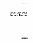
The RA81 has a data storage capacity of 456 megabytes in 16-bit word format. The RA81 connects to the
controller via the Standard Disk Interconnect (SDI) bus and may be used with any controller implementing
this bus. Additional disk drives can be connected to a controller to increase the data storage capacity. The
RA81 can also be connected in a dual-port arrangement permitting time-shared access by two controllers.
Performance Features
•
17.4 megabit per second peak transfer rate
•
28 ms average positioning rate
•
8.3 ms average rotational latency
Data Integrity
•
Protected media
•
Microprocessor-controlled servo
•
Automatic error correction
Hardware Features
•
Simple modular construction
•
Rugged design
•
Extensive microcode diagnostics
] -]
NOTE
Like other fixed-media devices, some method of
backup should be used to prevent loss of data in the
event of a failure. The following methods are recommended.
File Duplication-Important files should be duplicated often. Usually, this will involve copying the
data on a removable medium such as magnetic tape.
Journaling-The use of journaling is recommended in
transaction processing applications. This method allows reconstruction of files up to the last checkpoint
or backup.
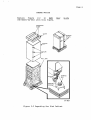
1.3 DRIVE DESCRIPTION
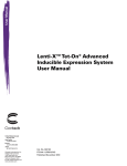
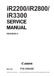
The RA81 is a self-contained disk drive with a built-in cooling system and dc power supply. See Figure 1-1.
The drive has optional slide rails and is designed to be inserted into a 19-inch wide RETMA equipment
rack. Up to three drives (one fixed mounted and two mounted on slides) can be included in a single cabinet.
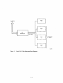
An RA81 Disk Drive subsystem is made up of an SDI controller (two controllers with the dual-port configuration) and one or more disk drives. Figure 1-2 shows the relationship between the subsystem components.
All RA81 disk logic is included within the drive. Three of the primary circuit modules (servo, microprocessor, and personality) are located directly under the logic access cover on top of the cabinet. These three
modules are mounted on hinges for ease of service. See Figure 1-3.
DC operating power for the logic circuits is provided by the drive power supply located inside the back of
the drive. Internal fans provide the necessary cooling for the power supply and for other drive components.
The RA81 Disk Drive conforms to UL, CSA, FCC, and VDE standards.
1.3.1 Head Disk Assembly
The sealed HDA contains the recording media (four platters), rotary positioner, read/write heads, and
preamplifiers. Seven of the platter surfaces are used for recording data. The eighth has dedicated servo
information used for positioning the read/write heads. The rotary positioner in the HDA is controlled by a
slave microprocessor closed-loop servo system. The RA81 uses both dedicated and embedded servo for
head positioning. This dual arrangement allows for coarse cylinder positioning from the dedicated servo
surface and fine cylinder positioning from embedded servo bursts which are read preceding each block of
data. The dedicated servo surface and the embedded servo data are written on the disk at the time the
HDA is manufactured.
1.3.2 Internal Drive Diagnostics
Two groups of internal diagnostics are used in the RA81 to permit error detection and fault isolation. The
first group of diagnostics is run automatically during the power-up sequence to validate initial operations.
Error codes for this test are displayed by indicators on the operator control panel. The second set of diagnostics is initiated and monitored through a diagnostic terminal as a maintenance function in the off-line
mode. These microcode diagnostics are for field service use only and are not part of the normal operating
functions.
The RA81 has a dual microprocessor (master and slave) control system. The master is located on the microprocessor module and the slave is located on the servo module. One microprocessor handles real-time
functions, such as servo control, while the other controls status checking. Both microprocessors share the
diagnostic responsibilities.
1-2
CZ-0775
Figure 1·1
The RA81 Disk Drive
DRIVE
TO/ FROM
o
CPU
r------,
I
DRIVE
:
1
I
L ____
---J
SDI
CONTROLLER
SDI CABLES
r----.
I
DRIVE
2
I
I
ADDITIONAL
DRIVES
L ____ -.1
r------,
I
DRIVE
3
I
I
L ____ -1
CZ-0730
Figure 1-2. Basic RA81 Disk-Subsystem Block Diagram
1-4
CHAPTER 1
INTRODUCTION
1.1 PURPOSE AND SCOPE
This manual describes the RA81 Disk Drive and tells how to install, checkout, and operate the equipment.
This manual is written primarily for the RA81 user except for Chapter 2 which is only for qualified field
service personnel.
1.2 GENERAL INFORMATION
The RA81 is a random-access, moving-head disk drive with non-removable media using a head/disk assembly (HDA). The HDA, a key feature of this drive, protects data and improves hardware dependability.
The RA81 has a data storage capacity of 456 megabytes in 16-bit word format. The RA81 connects to the
controller via the Standard Disk Interconnect (SDI) bus and may be used with any controller implementing
this bus. Additional disk drives can be connected to a controller to increase the data storage capacity. The
RA81 can also be connected in a dual-port arrangement permitting time-shared access by two controllers.
Performance Features
•
17.4 megabit per second peak transfer rate
•
28 ms average positioning rate
•
8.3 ms average rotational latency
Data Integrity
•
Protected media
•
Microprocessor-controlled servo
•
Automatic error correction
Hardware Features
•
Simple modular construction
•
Rugged design
•
Extensive microcode diagnostics
I-I
NOTE
Like other fixed-media devices, some method of
backup should be used to prevent loss of data in the
event of a failure. The following methods are recommended.
File Duplication-Important files should be duplicated often. Usually, this will involve copying the
data on a removable medium such as magnetic tape.
Journaling-The use of journaling is recommended in
transaction processing applications. This method allows reconstruction of files up to the last checkpoint
or backup.
1.3 DRIVE DESCRIPTION
The RA81 is a self-contained disk drive with a built-in cooling system and dc power supply. See Figure I-I.
The drive has optional slide rails and is designed to be inserted into a 19-inch wide RETMA equipment
rack. Up to three drives (one fixed mounted and two mounted on slides) can be included in a single cabinet.
An RA81 Disk Drive subsystem is made up of an SDI controller (two controllers with the dual-port configuration) and one or more disk drives. Figure 1-2 shows the relationship between the subsystem components.
All RA81 disk logic is included within the drive. Three of the primary circuit modules (servo, microprocessor, and personality) are located directly under the logic access cover on top of the cabinet. These three
modules are mounted on hinges for ease of service. See Figure 1-3.
DC operating power for the logic circuits is provided by the drive power supply located inside the back of
the drive. Internal fans provide the necessary cooling for the power supply and for other drive components.
The RA81 Disk Drive conforms to UL, CSA, FCC, and VDE standards.
1.3.1 Head Disk Assembly
The sealed HDA contains the recording media (four platters), rotary positioner, read/write heads, and
preamplifiers. Seven of the platter surfaces are used for recording data. The eighth has dedicated servo
information used for positioning the read/write heads. The rotary positioner in the HDA is controlled by a
slave microprocessor closed-loop servo system. The RA81 uses both dedicated and embedded servo for
head positioning. This dual arrangement allows for coarse cylinder positioning from the dedicated servo
surface and fine cylinder positioning from embedded servo bursts which are read preceding each block of
data. The dedicated servo surface and the embedded servo data are written on the disk at the time the
HDA is manufactured.
1.3.2 Internal Drive Diagnostics
Two groups of internal diagnostics are used in the RA81 to permit error detection'and fault isolation. The
first group of diagnostics is run automatically during the power-up sequence to validate initial operations.
Error codes for this test are displayed by indicators on the operator control panel. The second set of diagnostics is initiated and monitored through a diagnostic terminal as a maintenance function in the off-line
mode. These microcode diagnostics are for field service use only and are not part of the normal operating
functions.
The RA81 has a dual microprocessor (master and slave) control system. The niaster is 'located on the microprocessor module and the slave is located on the servo module. One microprocessor handles real-time
functions, such as servo control, while the other controls status checking; Both microprocessors share the
diagnostic responsibilities.
1-2
I
!
" IIliiiIiIIiIiii.UHlliUiIIIlifiiRiUliilM9f1
.1.
~ ........ uHdinii
CZ-0775
Figure 1-1
The RA81 Disk Drive
1-3
DRIVE
TO/ FROM
o
CPU
,------,
DRIVE
I
IL ____
1
I
---J
SDI
CONTROLLER
SDI CABLES
r-----,
I
DRIVE
2
I
I
L ____ --1
ADDITIONAL
DRIVES
,----,
I
L
I
____ --1I
DRIVE
3
CZ-0730
Figure 1-2. Basic RA81 Disk-Subsystem Block Diagram
1-4
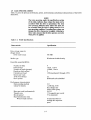
1.5 RA81 SPECIFICATIONS
Table 1-2 gives the primary performance, power, environmental, and physical characteristics of the RA81
Disk Drive.
NOTE
The term operating, under the specification section
of the table, indicates those values that must not be
exceeded while the drive is operational. The term
non-operating indicates those values that must not
be exceeded when the drive is being stored or in a
non-operating condition. Exceeding these values can
damage the drive when power is applied. Adhering to
these values ensures that the drive operates correctly
when power is applied.
Table 1-2
RA81 Specifications
Characteristic
Specification
Data storage capacity
(Single drive)
16-bit word format
456 MB
Media type
Winchester double density
Head disk assembly(HDA)
Number of disks
Disk surfaces
Number of heads (groups)
Heads per disk surface
Cylinders per head
Sectors per track
16-bit word format
Servo system
4
7 data, 1 servo
14 data, 1 servo
2
1258 (numbered 0 through 1257)
52
Dedicated and embedded
Performance characteristics
Disk encoding method
Linear bit density
3/2
11,400 bpi, 8550
flux changes per
inch at inner group
36,352
17.4 megabits per second
57 ns (nominal)
Bytes per track (unformatted)
Transfer rate
Bit cell period
Read initialization time
Write-to-read recovery
10 microseconds (excluding data separator
sync)
1-9
Table 1-2
RA81 Specifications (Cont)
Characteristic
Read-to write recovery
Data separator
synchronization
Rotational latency
Rotational speed
Average rotational latency
Maximum rotational latency
Head switch latency (switch
on a given cylinder)
Average seek
One cylinder
Maximum seek
Disk rotation start/stop times
Start time
Stop time
Maximum start/stop frequency
Physical characteristics
(Drive only)
Width (nominal)
Depth (nominal)
Height (nominal)
Weight (approx.)
Environmental limits
Temperature
Operating
Non-opera ting
Relative humidity
Operating
Specification
1 microsecond
10 microseconds
3600 rpm,
8.33 ms
16.66 ms
+ 2.5%,
- 3.5%
6 ms maximum
28 ms maximum
7 ms maximum
50 ms (1258 cylinders)
20 seconds maximum
20 seconds maximum
6 (3 minutes between cycles
with drive powered up and
ready during one of the
3-minute cycles)
44.5 centimeters (17.50 in.)
67.3 centimeters (26.50 in.)
26.4 centimeters (10.38 in.)
67.1 kilograms (148 pounds)
10 to 40 degrees C (50 to 104
degrees F) with a temperature
gradient of 20 degrees C/hour
(36 degrees F /hour)
- 40 to + 60 degrees C
( - 40 to + 140 degrees F)
10% to 85% (non-condensing)
with a maximum wet bulb
temperature of 28 degrees C
(82 degrees F) and a minimum
dew point of 2 degrees C
(36 degrees F)
1-10
Table 1-2
RA81 Specifications (Cont)
Characteristic
Specification
Shipping and storage
10% to 85% with no
condensation
Heat dissipation
644 watts (nominal)
Altitude
Operating
Non-opera ting
and shipping
Sea level to 2400 meters
(8000 feet) above sea level.
Note: Maximum allowable temperatures are reduced by a
factor of 1.8 degrees C/1000
meters (1 degree F /1000 feet)
for operation at higher
altitude sites
300 meters (1000 feet) below
sea level to 9000 meters
(30000 feet) above sea level
(actual or by means of cabin
pressurization)
Power
Voltage requirements
(Single phase)
120 volt, 60 Hz drives
90-128 volts ac, 60 plus
or minus 1 Hz
220-240 volt, 50 drives
184-256 volts ac, 50 plus
or minus 1 Hz
Current requirements
Starting current for
120 volt ac drives
35 ampere peak surge for
4 seconds
Running current for
120 volt ac drives
7.8 amperes rms at
120 volts
Starting current for
220-240 volt ac drives
18 ampere peak surge for
4 seconds
Running current for
220-240 volt ac drives
3.5 amperes rms
at 240 volts
Power requirements
Starting power for
120 volt ac drives
4200 watts at 120 volts
I-I I
Table 1-2
RA81 Specifications (Cont)
Characteristic
Specification
Running power for
120 volt ac drives
644 watts at 120 volts
Starting power for
220-240 volt ac drives
4320 watts at 240 volts
Running power for
220-240 volt ac drives
496 watts at 240 volts
Power factor
0.9
Line cord length
(from cabinet)
259 cm (8.5 feet)
Plug type
120 volts,60 Hz
Hubbe1 No.2611
NEMA No.L5-30P
DEC No.12-11193
(See Figure 2-1)
240 volts, 50Hz
Hubbel No.2321
NEMA No.L6-20P
DEC No.12-11192
(See Figure 2-1
1.6 RA81 OPTIONS
Table 1-3 lists the RA81 options.
All RA81 options in Table 1-3 include a 12-foot, shielded, inter-cabinet cable. If a longer cable is required
because of the dual-access feature, order cable BC06V-12 (12 feet), BC06V-25 (25 feet), BC06V-50 (50
feet),or BC06V-80 (80 feet).
1-12
Table 1-3
RA81 Options
Option
Description
RA81-AA
RA81-AD
RA81-CA
RA81-CD
RA81-EA
RA81-ED
RUA81-AA
RUA81-AD
RUA81-CA
RUA81-CD
RUA81-EA
RUA81-ED
RUA81-JA
RUA81-JD
456 MB drive, 120 V AC, 60 Hz, no cabinet
456 MB drive,240 VAC, 50 HZ,no cabinet
RA81-AA, H9642-AP cabinet, 60 Hz
RA81-AD, H9642-AR cabinet, 50 Hz
(3) RA81-AA, H9642-AP cabinet, 60 Hz
(3) RA81-AD, H9642-AR cabinet, 50 Hz
RA81-AA, UDA50, no cabinet
RA81-AD, UDA50, no cabinet
RA81-CA, UDA50, cabinet
RA81-CD, UDA50, cabinet
RA81-EA, UDA50, cabinet
RA81-ED, UDA50, cabinet
RA81-CA, (2) UDA50, cabinet
RA81-CD, (2) UDA50, cabinet
1-13
CHAPTER 2
INSTALLATION
2.1 SITE PREPARATION AND PLANNING
A certain amount of preparation and planning is necessary before installing the RA81 Disk Drive. The
paragraphs that follow discuss some of the points that should be considered.
2.1.1 Environmental Considerations
The RA81 is designed to operate in a business or light industrial environment. Temperature, humidity, and
altitude limits must be considered before the drive is installed. Refer to Table 1-2 for figures on environmental characteristics.
2.1.2 Cleanliness
Because the RA81 has a sealed HDA, dust particles should not be able to enter the area where the recording media is located. However, it is still desirable that the equipment be operated in the cleanest environment possible.
2.1.3 Floor Loading
The weight of one RA81 cabinet and disk drive is approximately 148.8 Kg (328 lb) with each additional
drive weighing approximately 67.1 Kg (148Ibs). A completely loaded RA81 cabinet (approximately 283
Kg or 6241bs) should not place any abnormal stress on a raised computer room floor. However, the weight
of existing equipment should be considered before installing additional drives.
2.1.4 Heat Dissipation
The heat dissipation of each RA81 may reach approximately 2200 Btu/hour. The approximate cooling
requirements for the complete system can be computed by multiplying this figure by the number of drives,
adding the heat dissipation figures of the other system components, and then adjusting the total figure to
allow for cooling system efficiency and any other factors.
2.1.5
Power and Safety Precautions
WARNING
Hazardous voltages are present inside this equipment. Installation and servicing should be performed
by a qualified and trained service person. Bodily injury or equipment damage may result from incorrect
servicing. Refer to the RA81 Service Manual for
proper instructions.
The RA81 will not cause any unusual fire or safety hazards to other computer equipment. The ac power
wiring in the computer system should be carefully checked, however, to be sure there is adequate capacity
for future expansion. The circuit breaker on the back of the power controller regulates the power to every
drive within the cabinet.
2-1
2.1.6 AC Power Wiring
The wiring used by Digital Equipment Corporation conforms to UL and other standards listed in Paragraph 1.3. This means the wire used as equipment ground is green and yellow. The ground wire carries no
load current (except in an emergency), but does carry leakage current. All equipment is shipped with a
grounding connection on its frame. The ac return line (also called the identified conductor, neutral, common, and cold lead) is blue. The ac return line must not be used to ground equipment since its purpose is to
conduct current.
The ac input line (brown wire) is also called the hot wire. Its purpose is to supply current to the system. The
ac plugs and receptacles used on the RA81 are shown in Figure 2-1.
PLUG
120V 60 Hz
30 A
1-PHASE
HUBBEL
w~
#2611
NEMA = L5-30P
DEC = 12-11193
240 V 50Hz
15 A
1-PHASE
RECEPTACLE
#2610
L5-30R
12-11194
G
X
@
HUBBEL
#2321
N EMA # L6-20P
DEC#12-11192
@
@
#2320
L6-20R
12-11191
NOTE: PIN CONFIGURATIONS OF PLUGS EXITING
POWER CONTROLLER IN CABINET.
CZ-0740
Figure 2-1
RA81 Electrical Plugs and Receptacles
2.2 EQUIPMENT UNPACKING AND EXTERNAL INSPECTION
When delivered, the RA81 equipment is packed in a cardboard container attached to a shipping skid or
pallet. Refer to Figure 2-2.
Before unpacking the equipment, check for external shipping damage. Report any damage to the DIGITAL Field Service or Sales Office and to the local carrier. Keep all packing material and receipts when a
damage claim is filed.
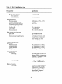
2.2.1 Unpacking the System on a Shipping Pallet
To unpack the equipment and remove it from the pallet, proceed as follows using Figure 2-2 as a guide.
1.
Remove all packing materials.
2.
Remove the four shipping bolts that fasten the drive cabinet to the pallet. Refer to the inset in
Figure 2-2.
2-2
SHIPPING
STRAPS
CZ-0564
Figure 2-2 Unpacking a System on a Shipping Pallet
3.
Build the ramp (Figure 2-3) to aid in rolling the disk drive off the pallet.
1.
Remove the plastic package containing the lag screw and nails from the bottom of the
ramp.
2.
Connect the ramp support block to the front of the shipping pallet with the lag screw.
3.
Nail the ramp to the top of its support block using the two nails provided.
2-3
PALLET
RAMP SUPPORT BLOCK
LAG SCREW
CZ-Q735
Figure 2-3
Building the Ramp
WARNING
At least two persons will be needed to perform the
next step of this procedure because of the weight of
the cabinet.
4.
Remove the four wooden blocks under the drive cabinet.
5.
Carefully roll the drive cabinet down the ramp.
2.2.2 Installing the Cabinet Levelers
Use the following procedure to install the cabinet levelers.
1.
Wheel the equipment cabinet to the correct location before installing the levelers.
2.
Unbolt and remove the four red shipping brackets and leveler nuts as shown in Figure 2-4.
3.
Assemble the four levelers as shown in Figure 2-5. Screw each leveler through the nut until it .
may be positioned into place without raising the cabinet. See inset in Figure 2-5.
2-4
..h~:....--- LEVELER NUT
~.J>~- RED SHIPPING
BRACKET
................
CZ·OS88
Figure 2-4 Shipping Bracket Removal
ill ~LEVELERNUT [!]
®
FLAT WASHER
@
LOCK WASHER
®
HEX NUT
CZ-0736
Figure 2-5
4.
5.
Cabinet Leveler Installation
Slide the leveler into the slots in the cabinet as shown. Screw the leveler down until solid contact is
made with the floor. See Figure 2-6.
Adjust until the cabinet is level.
2-5
"'------_d'
CZ-0737
Figure 2-6 Leveler Adjustment
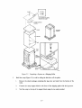
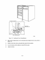
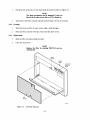
2.2.3 Removing Internal Shipping Brackets and Packing Material
Packing material and shipping brackets are inside the cabinet of each disk drive. Use the following procedure to remove this material and to prepare the drive for operation.
1.
Raise the logic access cover by turning the lock 90 degrees counterclockwise. Refer to Figure
2-7.
2.
Fold out the servo and personality modules. Remove the foam shipping pads between the modules (Figure 2-8).
3.
Return the modules to their original position and lock the logic access cover back in place.
4.
Raise the drive logic chassis assembly by pushing in on the latch behind the center slot in the
front bezel (Figure 2-7). Use a screwdriver blade to trip the latch.
2-6
LOGIC ACCESS COVER
LOGIC ACCESS
COVER LOCK
/
CZ-0739
Figure 2-7 Raising the Drive Logic Chassis Assembly
LOGIC ACCESS
COVER
SERVO MODULE
PERSONALITY
MODULE
FOAMPADS14~======~~========~)
U~ m0moo 00100 all 00 ooooom 00000 00001
CZ-0738
Figure 2-8
Foam Pad Removal
2-7
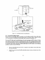
5.
Remove the four red shipping brackets that fasten the HDA to its mountings. See Figure 2-9.
The bracket next to the spindle motor requires special attention and should be removed last. To
remove the other three shipping brackets, loosen the three HDA mounting nuts. Also, completely remove the 5/16-inch hex-head bolts that hold the shipping brackets in place. Slide the
three shipping brackets out from under the HDA mounting nuts.
6.
Remove the shipping bracket next to the spindle motor by loosening the remaining HDA mounting nut and detaching the bolt and jam nuts. See Figure 2-9. Slide the shipping bracket out from
under the HDA mounting nut.
TOP VIEW
SPINDLE
MOTOR
...........r
11'1c5l):::!!~'!!!!!:.~~E!~~~~~--
SHIPPING
AND
JAM BOLT
NUTS
~
SHIPPING
BRACKET
5/16 HEX HEAD
BOLT
POSITIONER
LOCK LEVER
LOCK WASHER
SHOCK MOUNT
SHIPPING
BRACKET
FRONT VIEW
CZ-0741
Figure 2-9 HDA Details
2-8
NOTE
Save all shipping brackets and hardware for future
use when moving equipment.
7.
Tighten all four HDA mounting nuts.
8.
Ensure that the belt-tension lever is in the engaged position as shown in Figure 2-10.
9.
Place the positioner lock lever on the HDA in the UNLOCK position (Figure 2-9).
READ/WRITE
MODULE
HDA
BELT
TENSION
LEVER
RELEASED POSITION
CZ-0742
Figure 2-10 Belt Tension Lever
NOTE
An interlock switch prevents the spindle motor from
operating while the belt tension is released. See Figure 2-11. The belt-tension lever must be in the engaged position for spin-up.
2-9
CZ-0743
Figure 2-11
10.
Belt Tension Lever and Interlock Switch
Lower the logic chassis assembly until it latches.
2.3 RA8l INSTALLATION
An RA81 Disk Subsystem consists of an SDI disk controller and at least one RA81 Disk Drive. To install
the subsystem, it is necessary to connect the disk drive cabinet to the Central Processing Unit (CPU) cabinet, install the SDI cables, and program the unit address plug. If the system has more than three RA81s, it
is necessary to join two drive cabinets together.
2.3.1 Connecting Cabinets
The H9642 AP/AR (120/240 volt) cabinet will hold up to three disk drives. It comes equipped with two
end panels for stand-alone use. If more than three drives are required, a second drive cabinet may be joined
to the first. The H9642 BP/BR (120/240 volt) expansion cabinet comes with a joiner panel but no end
panels. The two cabinets may be joined by removing one of the end panels of the first cabinet and placing it
on the the outside edge of the expansion cabinet. Figure 2-12 shows the end and joiner panel locations.
Use the following procedure to join disk cabinets.
1.
Open the back door on the cabinet with the end panels by turning the hex lock counterclockwise.
Refer to Figure 2-13.
2-10
JOINER PANEL
END PANELS
Figure 2-12 End Panels and Joiner Panels
Figure 2-13
Opening the Back Door
2-11
2.
Remove the back cabinet door by unscrewing the ground wire and pulling down on the top door
latch. See Figure 2-14.
PULL DOWN ON DOOR LATCH
CZ-07B1
Figure 2-14 Back Door and End-Panel Lock Removal
3.
Lift the door off the bottom end panel lock.
4.
Loosen the two hex screws and remove the end panel lock from the base of the cabinet.
5.
Lift the end panel vertically to disengage it from the four key buttons on the side of the cabinet
frame. Refer to Figure 2-15.
6.
Unscrew the ground wire attached to the end panel.
7.
Remove the back end-panel lock from the expansion cabinet.
8.
Attach the ground wire just removed from the first cabinet to the exposed side frame of the
expansion cabinet.
9.
Attach the other end of the ground wire to the end panel just removed from the first cabinet.
2-12
TOP KEY BUTTONS
REMOVE CENTER SCREW
Figure 2-15
CZ-0774
End-Panel Bottom Key-Button Removal
10.
Lower the end panel over the keyhole buttons on the expansion cabinet.
11.
Secure the end panel by replacing the back end-panel lock.
12.
Remove the screws in the center of the two lower key buttons from the first drive cabinet.
13.
Engage the top two key buttons on the first drive cabinet (Figure 2-16) into the keyhole slots on
the expansion cabinet joiner panel.
2-13
TOP VIEWS:
JOINER PANEL
DRIVE
CABINETS
CABINET
EXPANSION
KEY BUnONS
DRIVE
CABINETS
DRIVE
CABINETS
CABINET
EXPANSION
CABINET
EXPANSION
CZ-0744
Figure 2-16 Connecting the Cabinets
14.
Adjust the cabinets until their fronts are flush.
15.
Remove the bottom trim panels from the front of the cabinets by removing the two screws at
their base. Refer to Figure 2-17.
2-14
Figure 2-1 7 Removing the Trim Panel Brackets
16.
Remove the two screws that hold the two retainer trim brackets nearest the side where the two
cabinets are joined. Refer to Figure 2-18.
17.
Place the front locking bracket over the retainer trim brackets.
18.
Bolt the two cabinets together with the four bolts, as shown.
19.
Replace the two bottom trim panels.
20.
Open the back door of the cabinets.
21.
Loosen the screws that hold the two back end-panel locks nearest the side where the two cabinets
are joined.
2-15
RETAINER TRIM BRACKET
FRONT LEFT
END-PANEL LOCK
FRONT LOCKING BRACKET
CZ-0760
Figure 2-18 Installing the Front Locking Bracket
22.
Slide the back locking bracket over the end panel locks and tighten the four screws. Refer to
Figure 2-19.
23.
Replace the back door and any end panel locks removed in this procedure.
24.
Lower the levelers until the cabinets are raised off their casters.
25.
Adjust the levelers.
2-16
=----==-11111
111111 111111. ''ill 11111
111111
111111
111111 IlIlIi
11111
111111 111111
111111
111111,
111111 111111
CPU CABINET
1111 11111111111
11111 '1111
111111
111111
'11111
11111
111111
111111
JlJII
11 1111 ,
11111' 1111111111111
11111
DRIVE CABINET
111111
11111
11111
",Ii
111111
1111111
lill
11111
BACK LOCKING BRACKET
CZ-0746
Figure 2-19 Installing the Back Locking Brackets
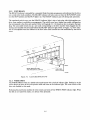
2.3.2 External SDI Cabling Procedure
Both internal and external SDI cables are mounted in the I/O bulkhead assembly. Internal SDI cables
connect to the top of the bulkhead and external cables connect to the bottom. Refer to Figures 2-20 and
2-21. The procedure for connecting the internal SDI cables is discussed in Paragraph 2.4.7.
The external SDI cables must be installed between the central processing unit (CPU) cabinet, I/O bulkhead connector, and the drive cabinet I/O bulkhead connector. The CPU I/O bulkhead connector should
have already been installed. If not, refer to the installation procedure in the appropriate disk drive controller user guide. When the CPU cabinet I/O bulkhead connector has been installed, follow the instructions in
the appropriate disk controller user guide to install the SDI cables at the CPU cabinet. Use the following
procedure to install the external SDI cables.
1.
Plug the external SDI cable into the Port A receptacle on the bulkhead. External SDI cables
enter from the bottom.
2.
Install the two screws that hold the SDI cable shield terminator in place and tighten them. Refer
to Figure 2-20.
2-17
~
-- -------- -- i :
-
_________ --
rl----
:
MO~::-~
SCREWS
I/O BULKHEAD
FOR FIRST
ADD-ON
I/O BULKHEAD
FOR SECOND
ADD-ON
EXTERNAL
SDI CABLES
CZ-0764
Figure 2-20 SDI Cable Shield Terminator Installation
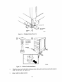
3.
Clamp the external SDI cables to the cable entry retainers below the I/O bulkheads with either a
hose clamp or tie wrap. Refer to Figure 2-21.
4.
If more than one drive is mounted in the cabinet, more SDI cables must be installed. Refer to
the RA8! add-on installation procedure (Paragraph 2.4) for instructions.
2-18
DISK DRIVE
DRIVE
CIRCUIT
BREAKER
POWER
CORD
AC OUTLET FOR
DRIVE POWER ON FRONT
OF POWER CONTROLLER
~~==O=~~~_POWER
LAMP
LOCAL/REMOTE SWITCH
Figure 2-21
CZ-0765
Single Drive External SDI Cables
2.3.3 Programming the Drive Unit Address Plug
The READY cover on the operator control panel is also the drive unit address plug. The drive unit numbers
between 0 and 251 must be programmed into this plug. The plug comes as "Unit 0". To set up a drive unit
number other than zero, remove the READY switch cover from the control panel and cut off the tabs that
add up to the required number. Figure 2-22 shows the binary value represented by each tab.
16
REAR PIN CONFIGURATION
CZ-0747
Figure 2-22 Drive Unit Address Plug
2-19
For example, if unit number 7 is required for a specific drive, tabs 1, 2, and 4 would have to be cut off the
switch cap. If unit number 113 is required, tabs 64,32, 16, and 1 must be removed. Leave all tabs on ifunit
number 0 is required.
After the drive unit number has been selected, place the gummed label with the corresponding number in
the recessed area on the front of the switch cover. Replace the switch cover on the operator control panel.
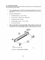
2.4 RA81 ADD-ON INSTALLATION
Use the following procedure to install additional drives in a cabinet.
CAUTION
Do not try to complete the add-on instalhition without the help of a second person because of the weight
of the drives.
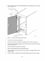
2.4.1 Remove the Front Trim Panel
The first add-on drive should be placed in the center bay of the RA81 cabinet and the second in the bottom
bay. Remove the trim panel at the proper location by unscrewing the four 10-32 hex nuts that hold the
panel to the cabinet frame. These nuts can be reached through the back of the cabinet. Refer to Figure
2-23.
HEX NUT
10-32
(4 PL)
TRIM
PANEL
~
,/
/~
8
CZ-OS77
Figure 2-23
Removing Cabinet Trim Panel
2-20
2.4.2 Install the Slide Assembly
Each RA81 add-on drive must be mounted in the cabinet on a slide assembly. Use the following procedure
to install the slides in the drive cabinet.
1.
Screw a chassis slide bracket on to each end of the left and right chassis slides. Use two 8-32 x
5/16 inch phillips head sems screws (screws with star washers attached) to mount each. Refer to
Figure 2-24.
2.
Set aside the following hardware:
3.
•
Four phillips head screws - 10-32 x 5/8 inch
•
Four lock washers - 0.380 inch O.D. x 0.200 inch I.D.
•
Two slide mount spacers (two holes)
•
Four phillips head sems screws - 10-32 x 1/2 inch
•
Four nut bars (four holes)
Mount the chassis slides to the front vertical upright as shown in Figure 2-25. If this is a first
add-on drive (center bay), use mounting holes 27 and 31, counting from the bottom. Notice that
this installation to the front vertical upright needs both a slide mount spacer and a nut bar.
RIGHT
CHASSIS
SLIDE
CHASSIS
SLIDE
BRACKETS
NOTE
1. REPEAT FOR LEFT CHASSIS SLIDE.
CZ·0578
Figure 2-24 Chassis Slide Bracket Installation
2-21
VIEWED FROM FRONT OF CABINET
SLIDE MOUNT
SPACER
NUT
BAR
CABINET FRONT
LEFT UPRIGHT
CHASSIS SLIDE
BRACKET
LOCK
,.
W~~/
<
PHILLIPS HEAD SCREWS
10-32 X 5/8"
NOTE
1.
REPEAT FOR FRONT RIGHT UPRIGHT.
Figure 2-25
4.
CZ·OS79
Mounting Chassis Slide to Front Upright
Mount the chassis slides to the back vertical uprights as shown in Figure 2-26. Note that only a
nut bar is used here with sem screws. Use the same mounting holes as specified in Step 3 above.
VIEWED FROM FRONT OF CABINET
PHILLIPS HEAD
SEM SCREWS
10-32 X 1/2"
NUT
BAR
CHASSIS
SLIDE
BRACKET
LEFT BACK
VERTICAL UPRIGHT
NOTE
1. REPEAT FOR RIGHT BACK VERTICAL UPRIGHT.
CZ-0749
Figure 2-26 Mounting Chassis Slide to Back Upright
2-22
5.
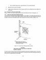
Mount the electrostatic discharge bracket over the chassis slide bracket on the back left vertical
upright. Pass the two sem screws through the two center holes of the chassis slide bracket and
fasten them to the nut bar inside. Refer to Figure 2-27. If this is the first add-on drive (center
bay), use mounting holes 28 and 30. If this is the second add-on drive (bottom bay), use mounting holes 10 and 12.
VIEWED FROM BACK OF CABINET
LEFT VERTICAL UPRIGHT
VIEWED FROM BACK
"-
LEFT CHASSIS
SLIDE BRACKET
ELECTROSTATIC
DISCHARGE
BRACKET
"-
"-
"~
PHILLIPS HEAD
SEM SCREWS
10-32 X 1/2"
CZ-0750
Figure 2-27 Mounting the Electrostatic Discharge Bracket
6.
Insert the two cable retainer springs in to the back of the left and right chassis slides as shown in
Figure 2-28. Push the cable retainer springs until they latch into place.
7.
Mount an 11/ 16-inch cable clamp on to each cable retainer spring, as shown. Each cable clamp
should be mounted on inside (drive side) of the cable retainer spring.
8.
Install the drive detent latch on the left vertical upright (back view). See Figure 2-29. Ensure
that the drive detent latch will not move freely but is loose enough that it can be adjusted later.
If this is a first add-on drive (center bay), use mounting holes 36 and 37. If this is a second
add-on drive (bottom bay), use mounting. holes 18 and 19.
2-23
VIEWED FROM FRONT OF CABINET
PHILLIPS HEAD
SEM SCREW
10-32 X 1/2"
CABLE
RETAINER
SPRING
SPACER
CABINET
SLIDE
MEMBER
/
~_
"
CABLE CLAMP
11/161NCH
~
/"~
FLAT WASHER
/
0.500 aD X 0.281 ID
PHILLIPS HEAD SCREW
10-32 X 5/8"
INTERMEDIATE
SLIDE
MEMBER
NOTE
1. REPEAT FOR CHASSIS SLIDE ON RIGHT SIDE.
CZ-0751
Figure 2-28 Installation of Cable Retainer Springs
VIEWED FROM RIGHT SIDE
OF CABINET
PHILLIPS HEAD
SEM SCREWS
10-32 X 1/2"
DRIVE
DETENT
LATCH
~
" " .......'- '......
.......
.......
'-
"
CABINET BACK
LEFT VERTICAL
UPRIGHT
CZ-0752
Figure 2-29 Installation of Drive Detent Latch
2-24
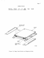
2.4.3 Remove the Internal Shipping Brackets and Packing Material
Remove the shipping brackets and packing material from inside the drive using the procedure described
previously in Paragraph 2.2.3.
2.4.4 Mount the RA81 on the Slides
Use the following procedure to mount the drive on its slides.
1.
Install the left and right mounting rails onto the sides of the disk drive as shown in Figure 2-30
using ten 6-32 kep nuts.
RIGHT
MOUNTING
RAIL
- _ - ' / n.......
KEP NUT
6-32 X 5/16"
(5 PL EACH SIDE)
NOTES
1.
REPEAT FOR LEFT MOUNTING RAIL.
CZ-0584
Figure 2-30 Installation of Drive Mounting Rails
2.
Remove the HDA to reduce the weight of the drive using the following procedure. Refer to
Figures 2-31 and 2-32.
1.
Raise the drive logic chassis. Refer to Paragraph 2.2.3, Step 4.
2.
Unplug connector P502 from the read/write module. See Figure 2-31.
3.
Unplug connectors P602 and P603 from the preamplifier module. Refer to Figure 2-31.
4.
Place the belt tension lever in the release position. Refer to Figure 2-31
2-25
READ/WRITE
MODULE
BELT
TENSION
LEVER
HDA
RELEASED POSITION
"'@- ENGAGED
POSITION
HDA HOLDDOWN - - - - - . ~.
NUTS (4)
~
CZ-0770
Figure 2-31
Removal of HDA Cable Connections
5.
Remove the four HDA retaining nuts.
6.
Place the positioner lock in the LOCK position. Refer to Figure 2-32.
CAUTION
The HDA could be damaged if the previous step is
not performed.
7.
8.
Remove the HDA from the drive by lifting from diagonally opposite corners. Refer to
Figure 2-32.
Place the HDA on a level surface in the vertical position only. Feet are provided on the
front cover of the HDA for this purpose.
2-26
CAUTION
Do not place the UDA in a horizontal position (on
the pulley). The speed and temperature transducers
mounted on the bottom of the UDA could be damaged.
If the UDA is going to be moved to another location,
tape the UDA spindle pulley in place to prevent
movement of the spindle. Any movement of the spindle could damage the heads.
It is important to use a good nylon reinforced packing tape. Masking tape should never be used as it is
not strong enough.
PLASTIC BULKHEAD FEET
CZ-8021
Figure 2-32 HDA Positioner Lock.
3.
4.
Extend the cabinet stabilizer as shown in Figure 2-33.
Extend each chassis slide all the way forward until it locks. See Figure 2-34.
WARNING
A second person is needed to place the drive on the
chassis slides because of the weight of the disk drive.
2-27
CZ-0753
Figure 2-33
Extending Cabinet Stabilizer
DRIVE
CABINET
RA81
DISK
DRIVE
•
SLIDE
ASSEMBLY
PHILLIPS HEAD
SEM SCREWS
8-32 X 5/16
(2 EACH SIDE)
CZ-0754
Figure 2-34 Extending the Chassis Slides
5.
With the help of a second person, lift the drive and place it on top of the chassis slides as shown
in Figure 2-34. Push the drive toward the back of the cabinet until its mounting rails touch the
stop.
2-28
6.
Fasten the drive to the chassis slides using four 8-32 x 5/16 inch phillips head sem screws, as
shown.
7.
Extend the drive forward on the slides.
8.
Replace the HDA using the following procedure.
1.
Ensure that the drive belt is centered on the motor pulley. The other end of the belt should
be even with the top of the nylon rollers on the wing pivot assembly. See Figure 2-35.
CZ-0767
Figure 2-35
Wing Pivot Assembly
CAUTION
Damage to the HDA, drive belt, or nylon rollers
could result if the drive belt is not aligned correctly.
2.
Lift the HDA by grasping two diagonally opposite corners, then lower the HDA over the
four mounting bolts.
3.
Replace the four nuts and washers on the HDA.
4.
Connect P602 and P603 to the read preamplifier module on the front of the HDA.
5.
Connect P502 to the read/write module.
6.
Place the belt tension lever in the engaged position. See Figure 2-10.
2-29
7.
9.
10.
Turn the HDA positioner lock counterclockwise to the unlocked position.
Slide the drive back into the cabinet.
Adjust the drive detent latch so that it prevents the drive from sliding forward and tighten the
la tch screws.
2.4.5 Program the Drive Unit Address Plug
Program the drive unit address plug using the procedure described previously in Paragraph 2.3.3.
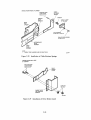
2.4.6 Connect the Electrostatic Discharge Bracket
The electrostatic discharge bracket grounds the disk drive to the cabinet. To complete this ground path, the
bottom left screw on the drive power supply should be removed. This same screw should then be inserted
through the electrostatic discharge bracket and screwed back into place as shown in Figure 2-36.
<tl
~
<tl
<tl
<tl
<tl
cg
<tl
ELECTROSTATIC
DISCHARGE
BRACKET
cg
cg
LEFT BACK OF
DISK DRIVE
NOTE
1. REMOVE POWER SUPPLY SCREW TO
SLIDE DRIVE FORWARD. REPLACE SCREW
THROUGH BRACKET EACH TIME THE DRIVE
IS SLID BACK INTO CABINET.
CZ-0755
Figure 2-36 Electrostatic Discharge Bracket Details
CAUTION
This ground connection must always be made before
the drive is operated.
To slide the drive forward, remove the screw that holds the electrostatic discharge bracket to the power
supply and push on the drive detent latch. Remember to reconnect the electrostatic discharge bracket each
time the drive is pushed back into the cabinet.
2-30
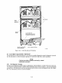
2.4.7 Install the Internal SDI Cables
The two internal SDI cables that exit from the back of the add-on drive must be connected to the top of the
I/O bulkhead assembly. The external SDI cable that connects the drive cabinet to the disk controller must
be mounted on the bottom of the I/O bulkhead assembly. If two disk controllers are used (dual-port operation), a second external SDI cable must be installed. The SDI cables must be connected to the I/O bulkhead before the bulkhead is connected to the drive cabinet. Figures 2-37 and 2-38 show the electrical
wiring for add-on disk drives. Use the following procedure to install the SDI cables.
_OUT 1ApN'
c=J
c=J
DRIVE 0
.OUTl~ A"rlr./
AC
LIN ES
~"
1--
B
DRIVE 1
--l
I
I
I
I
L-____ ~
I
POWE R
CONT ROllER
•
!
I/O BULKHEAD
~~~~
SDI CABLES
~ i
I
I
B 110UT ?N
DRIVE
SEQUENCE
TERMINAT OR
SDI CONTROllE RA
PORT 0
SDI CONTROllER B
PORT 1
PORT 0
PORT 1
NOTES
1.
HEAVY LINE INDICATES THE DRIVE
SEQUENCE CABLE.
CZ-0758
Figure 2-37 Cabling for a Two-Drive System
2-31
• OUTl AI B"r IN
.OUT1~ ~NT
c:::J
c:::J
c::J
DRIVE 0
.OUT1~ A"r~c:::J
AC
LIN
15
1'--'-..
PO WER
CO NTROLLER
I
AC
L1\
.OUT1~ A"rIN~
~ f-o
r-I
I
DRIVE 1
CJ
,--
R
--,.
DRIVE 3
I
I
__ J
I
I,
--
---1
I
I
I
L __
DRIVE 2
~~ ~ ~
n
~
•
I
SDI CABLES
,
I
__.J
I
J6
CbttJCb
J5
!
!
0 .0.1 0 []
B
A
B A
ID
D
l~
II
0
0
B A OUT IN
lU-
J3
SDI CABLES
I/O
BULKHEAD
1/0
BULKHEAD
J4
POWER
CONTROLLER
I oI
0
0
A OUT IN
DRIVE SEQUENCE
TERMINATOR
NO TES
1.
ALL PORT A CONNECTIONS GO TO SDI
CONTROLLER A. ALL PORT B CONNECTIONS
GO TO SDI CONTROLLER B.
2.
HEAVY LINE INDICATES DRIVE SEQUENCE
CABLE.
EXTERNAL DRIVE /
SEQUENCE CABLE
CZ-0759
Figure 2-38 Cabling for a Three- and Four-Drive System
1.
Locate the Port A SDI cable where it exits the back of the disk drive. Find the end of the cable
and plug the connector into Port A on the top of the I/O bulkhead assembly. Note the orientation key.
2.
Screw the Port A SDI cable shield terminator into the I/O bulkhead assembly. Early versions of
the disk drive will need separate screws to mount the shield terminator. Later versions will have
captive hardware. Refer to Figure 2-39.
3.
Repeat Steps 1 and 2 for the Port B SDI cable.
4.
Plug the SDI cable from the first disk controller into the Port A connector on the bottom of the
I/O bulkhead assembly. Note the orientation key.
2-32
M~;;:NG~
SCREWS
1/0 BULKHEAD
FOR SECOND
ADD-ON
1/0 BULKHEAD
FOR FIRST
ADD-ON
EXTERNAL
SOl CABLES
CZ-0764
Figure 2-39 Connecting SDI Cable Shield Terminators
5.
Screw the shield terminator of this cable into the I/O bulkhead assembly as in Step 2.
6.
If a second disk controller is used, mount its SDI cable into Port B on the I/O bulkhead assembly.
2.4.8 Mount the I/O Bulkhead
An I/O bulkhead assembly must be installed on the back base of the drive cabinet for each add-on drive.
Screw the I/O bulkhead assembly on to the back of the cabinet as shown in Figure 2-40. Mount the I/O
bulkhead assembly in the drive 1 location for the first add-on drive. Mount the I/O bulkhead assembly in
the drive 2 location for the second add-on drive.
2.4.9 Install the Drive Sequence Cables
Figures 2-37 and 2-38 show the electrical wiring diagrams for add-on drives. Use them as a reference when
installing drive sequence cables, as follows.
1.
Unplug the drive sequence cable from the output connector on drive 0 (top drive) done by raising the back cover and removing it from the cable clamp. Refer to Figure 2-41.
2.
Plug the drive sequence cable described in Step 1 into the output connector on drive 1 for one
add-on, or into the output connector on drive 2 for two add-ons.
3.
Install the new 8-foot cable between the output connector of drive 0 and the input connector on
drive 1. If a second add-on drive has been installed, connect another 8-foot drive sequence cable
between the output connector of drive 1 and the input connector of drive 2.
2-33
•
DRIVE SEQUENCE
CABLE BULKHEAD
./....~~-I/O BULKHEAD
FOR FIRST
ADD-ON
1/0 BULKHEAD
FOR SECOND
ADD-ON
CZ-0772
Figure 2-40 Mounting the I/O Bulkhead Assembly
2-34
DRIVE SEQUENCE
CABLES
DRIVE SEQUENCE
CABLES
CZ-0769
Figure 2-41
Drive Sequence Cable Installation
4.
Tie-wrap the drive sequence cable to the existing SDI cable clamps.
5.
Add a cable between the drive sequence bulkheads on each drive cabinet when a second cabinet
is used. Refer to Figures 2-38 and 2-41.
2-35
2.4.10 Connect AC Power
Plug the ac power cord from each add-on into the ac receptical on the power controller at the base of the
cabinet. Refer to Figure 2-42.
J6
AC PLUG
DRIVE 1
CZ-07S7
Figure 2-42 Power Controller AC Receptacles
2.4.11 Route and Clamp the Cables
The cables from the add-on drives must now be routed and clamped to allow the drive to be extended on
the slide rails. Route and clamp the cables as follows.
1.
Mount the spacers and cable clamps into the back vertical uprights as shown in Figure 2-43. If
this is the first add-on drive (center bay), mount the cable clamps in hole 44 of the left and right
vertical uprights. If this is the second add-on drive (bottom bay), mount the cable clamps in
mounting hole 23 of the left and right vertical uprights.
2-36
KEP NUT
10-32 X 3/8"
STANDOFF
10-32,6-32
CABLE CLAMP
3/8"
FLAT WASHER
0.375 OD X 0.156 ID
CZ-0771
Figure 2-43
Connecting Cable Clamps to Uprights
2.
Use the 15 cable ties provided with each add-on to route and tie the cables where indicated in
Figure 2-44. Three cable ties are used on the ac power cord and seven ties are used on the SDI
and drive sequence cables.
3.
Tie wrap the cables to the clamp mounted previously on the back of the chassis slides.
4.
Form a service loop approximately eight inches in diameter in the cables as shown in Figure
2-44. Fasten the output of the service loop with the cable clamps installed on the vertical
uprights in Step 1 above.
5.
Tie wrap the cables at the bottom of the cabinet to the cable clamp at mounting hole 14.
2-37
DISK DRIVES
DRIVE
CIRCUIT
BREAKERS
AC OUTLETS FOR
DRIVE POWER ON FRONT
OF POWER CONTROLLER
POWER
LAMP
POWER CONTROLLER
CIRCUIT BREAKER
LOCAL/REMOTE SWITCH
CZ-0766
Figure 2-44 Cable Routing and Clamping
2.5 RA81 DRIVE DIAGNOSTIC CHECKOUT
The paragraphs that follow describe how to run the drive-resident diagnostics using the diagnostic terminal.
Use this procedure to verify the proper operation of each RA81 Disk Drive after installation.
NOTE
Checkout procedures should be used only by trained
maintenance personnel.
2.5.1 The Diagnostic Terminal
A field service diagnostic terminal used to communicate with the RA81 is stocked with every spares kit.
The diagnostic terminal utilizes a standard ASCII keyboard and an RS232 interface. Any EIA-compatible
terminal set at 300 baud can be used to communicate with the drive to run the diagnostic tests. See Appendix A for instructions on how to use this terminal.
2-38
2.5.2 Applying Power to the Drive
Use the following procedure to apply power to the drive.
1.
Verify that the ac circuit breakers on the power control unit and each disk drive are in the OFF
position. Refer to Figure 2-44.
2.
Plug the ac power cord from the drive into the ac power receptacle on the power control unit at
the bottom of the cabinet if this is an add-on drive.
3.
The LOCAL/REMOTE switch on the power controller must be in the LOCAL position to ensure drive operation since no power sequencing cable is used.
4.
Plug the control unit ac power cord into an external ac power source.
5.
Place the ac circuit breaker on the power control unit in the ON position.
2.5.3 Checkout
Use the following procedure to verify drive operation.
1.
Ensure the drive is in the off-line state by placing both port select switches (A and B) in the OUT
position.
2.
Place the RUN/STOP switch in the OUT position.
3.
Open the logic access cover and raise the servo and personality modules.
4.
Make sure that all cable connectors are firmly seated in the mating connectors.
5.
Place the ac circuit breaker on the back of the drive in the ON position. Internal drive diagnostics (hardcore test sequence) run automatically when the drive circuit breaker is turned on. All
front-panel lights turn on while the drive runs these diagnostics. If the drive successfully passes
the hardcore test sequence, the front-panel indicators go off in 3-4 seconds. If an error code is
displayed on the front-panel indicators, refer to the fault isolation procedures in the RA81 Service Manual.
NOTE
Do not have the diagnostic terminal connected to the
drive at this time. Doing so could cause the hard core
tests to fail.
6.
The drive idle loop tests start automatically about 30 seconds following the end of the hardcore
test sequence. Allow about 30 seconds for the execution of these tests. Observe the microprocessor LEDs for a display of a hexadecimal E7 after a successful completion. Errors are indicated
by a fault code in the front-panel lights. Refer to the fault isolation procedures in the RA81
Service Manual.
7.
Connect the diagnostic terminal to the RS232 port connector in the drive. Refer to Figure 2-45.
2-39
RS232
DIAGNOSTIC
TERMINAL
CONNECTOR
DIAGNOSTIC
TERMINAL
POWER
CONNECTOR
"
," '
P306
:[]lil
0
0
0
o0 000000000 DO DODD
MOTOR
START
CAPACITOR
P307
MICROPROCESSOR
MODULE
TOP VIEW OF DRIVE
CZ-0773
Figure 2-45 Diagnostic Terminal Connections
2-40
8.
Key in a CTRL C (Te) on the terminal keyboard to place the drive in the diagnostic monitor
mode. A diagnostic prompt (RA81 » is then displayed by the terminal.
NOTE
The drive idle loop test sequence is repeated continuously until a CTRL C (TC) is input. The test will
complete the current sequence before displaying the
RA81> prompt.
9.
Depress the continue (CaNT) key on the terminal. This disables the automatic X-On, X-Off
feature of the terminal allowing the testing to be continuous.
10.
Run the entire drive sequence test with the drive spun down by typing RUN DIAG on the terminal. As the sequence is executed, the following messages are displayed by the terminal:
IRA81-COMPlETED TEST:DIAG SUBTEST:xx
IRA81-COMPlETED TEST:DIAG SUBTEST:xx
IRA81-COMPlETED TEST:DIAG SUBTEST:xx
IRA81-COMPlETED TEST:DIAG SUBTEST:xx
RA8h
The microprocessor LEDs increment and then settle on a hexadecimal E7 while the sequence is
being executed. The display of the prompt indicates successful completion of the test sequence.
The following terminal display means that one of the tests has failed. When a test fails, refer to
the fault isolation procedures in the RA81 Disk Drive Service Manual.
IRA81-TEST:DIAG SUBTEST:xx ERROR:xx UNITxxx
IRA81-FRU-xxxx,xxxx,xxxx
11.
After passing the above test, spin up the drive by pushing the RUN/STOP switch to the IN
position. The drive should respond with the following message:
FRONT PANEL FUNCTION IN PROGRESS
A diagnostic sequence is automatically executed during spin-up.
The microprocessor LEDs remain off while the drive spins up. When it is up to speed, the LEDs
display the E7 code and the terminal displays the following:
.
2-41
%RA81-COMPLETED TEST:DIAG SUBTEST:xx
%RA81-COMPLETED TEST:DIAG SUBTEST:xx
%RA81-COMPLETED TEST:DIAG SUBTEST:xx
%RA81-COMPLETED TEST:DIAG SUBTEST:xx
RA8h
The terminal displays the most likely FRU to replace if an error condition is noted during the
above sequence. The diagnostic takes about 45 seconds to complete. Do not proceed to the next
step until the prompt is displayed.
12.
Type RUN DIAG to initiate the entire drive sequence test with the drive spun up. The terminal
should display messages similar to those when the drive was spun down. If an error is indicated
during this test, the terminal will display the most likely FRU to replace. The microprocessor
LEDs increment and then settle on a hexadecimal E7 while the sequence is being executed
(about 7 minutes).
13.
When the RA81> prompt is displayed, respond by typing in SET DIAG LOOP=HALT to place
the drive in a continuous loop mode, halting only on an error.
14.
As soon as the drive returns with the RA81> prompt, respond by typing RUN DIAG. The
entire drive sequence diagnostics are once again initiated. Run this test sequence for 25 minutes.
If any errors occur during this time, the terminal will indicate the most likely failing FRU. Refer
to the RA81 Service Manual for the list of FRUs.
15.
After the above test has run for 25 minutes without an error, key in CTRL C (TC) to terminate
the loop mode and the test.
16.
As soon as the drive returns an RA81 > prompt, type EXIT to exit the diagnostic monitor mode.
NOTE
CTRL Z (lZ) can also be used to exit the monitor
mode. One or both of the port select switches can be
pushed in to accomplish the same.
17.
Push in the desired port select button to place the drive in an available state.
18.
Run the main system diagnostics.
19.
Upon completion of all tests on each drive, disconnect the diagnostic terminal, fold the servo and
personality modules back into their proper positions, and then close and secure the logic access
cover on the drive.
2-42
3.1.3 UNIT/READY
The READY indicator is preceded by a successful (fault-free) spin-up sequence and indicates that the drive
is in a read/write ready condition. The READY indicator will only come on when the RUN/STOP switch
is in the RUN position and the RUN light is on. The READY indicator goes off during seek operations.
The numbered switch cover over the READY indicator light is also a logic plug which distinguishes one
drive from another in multi-drive arrangements. The switch cover has a unique cam-coded configuration
that corresponds to the drive unit number. Refer to Paragraph 2.3.3 for details on how to program the logic
plug. The cam-coded switch sets up a unit code corresponding to the drive number when plugged into the
mating cam-encoded switch located behind the READY indicator light. Refer to Figure 3-2. Drive selection is accomplished when the address on the drive select lines matches the code established by the switch
cover.
B
---
READY INDICATOR LAMP
AND MICROSWITCH CONTACTS
--
----------
~~-CODED
SWITCH COVER
CZ-0756
Figure 3-2 Cam-Coded Switch Cover
3.1.4 WRITE PROT
The WRITE PROT switch is a double-action push button with a built-in indicator light. Pushing in on this
switch places the drive in the write protect mode and turns on the indicator light. The write circuits of the
drive are disabled in this mode.
Releasing the push button enables the write circuits and turns off the WRITE PROT indicator light. When
the disk is not read/write ready, it is always write protected.
3-5
3.1.5 A and B Port Select Switches
The RA81 Disk Drive has two port select push button switches. These double-action switches (A and B)
have built-in lights that indicate the port through which the drive is being accessed. If the drive is equipped
with dual-port abilities, anyone of three modes can be selected with the A and B switches.
•
Port A operation only
•
Port B operation only
•
Port A/B (programmable) operation
When the Port A button is pushed in and the Port B button is out, only Port A can be accessed by the
controller. During the opposite condition, only Port B can be accessed. However, when both push buttons
are in at the same time, either Port A or Port B can be accessed by the controller. When either or both
buttons are out, the drive is off-line to the port or ports indicated.
The drive will indicate that it is on-line to controller A by lighting the A switch, on-line to controller B by
lighting the B switch, or not on-line to either controller by leaving both lights off. During normal operation,
the indicator lights will never be on at the same time. The on/off conditions of the port indicator lights do
not always follow changes in switch positions immediately. For example, if the drive is on-line to controller
A, the indicator light for A will be on. If the switches are then reset for access by controller B, the A
indicator will stay on until the drive is actually on-line to controller B. Then and only then will the indicator
lights change state.
3.2 CIRCUIT BREAKERS
Each disk drive has a circuit breaker on the back panel as well as a breaker on the back of the power
controller in the bottom of the cabinet. Access to these breakers is through the back door of the cabinet.
The breakers on the drive control the application of ac power to the drive dc power supply, the cooling fans,
and the spindle motor. This breaker must be on before the drive will operate.
The power controller breaker regulates the application of ac power to all assemblies within the RA81 cabinet and must be turned on before the drive breaker can be effective.
3.3 DRIVE OPERATION
3.3.1 Spin-Up
Push in the RUN/STOP button on the drive front panel to spin-up the drive. The RUN indicator will light
immediately and the READY indicator will come on as soon as the drive has completed the spin-up cycle.
3.3.2 Spin-Down
Release the RUN/STOP button (out position) on the drive front panel to stop the drive. The READY
indicator will go off immediately and the RUN indicator will go off as soon as disk rotation stops.
3.3.3 Removing'RA81 Power
Do a spin-down as described above. After the RUN indicator has gone off, turn the drive breaker on the
back panel off and disconnect the cord going to the power controller. This will remove all power to the
drive.
3.4 CUSTOMER CARE
The airfiIter in the logic chassis assembly should be inspected and cleaned every six months.
3.4.1 Air-Filter Removal
To remove the air filter, proceed as follows:
3-6
1.
Pull down the access door on the front bezel of the drive. Refer to Figure 3-3.
NOTE
The hinge mechanism can be damaged if tools are
placed on the open access door or if it is leaned on.
2.
Take hold of the filter material and pull outward until it is free of the bezel.
3.4.2 Cleaning
1.
Wash the foam air filter in warm water using a mild detergent.
2.
Rinse the filter material with clear water and then allow to dry.
3.4.3 Replacement
1.
Slide the filter into place inside the bezel.
2.
Close the access door.
NOTE
Replace the filter by ordering DIGITAL part no.
7422816-00.
OPERATOR
CONTROL
PANEL
AIR
FILTER
./
./
./
./
"" ""
./
,/
,/
CZ-0599
Figure 3-3 Air-Filter Removal
3-7
3.1.3 UNIT/READY
The READY indicator is preceded by a successful (fault-free) spin-up sequence and indicates that the drive
is in a read/write ready condition. The READY indicator will only come on when the RUN/STOP switch
is in the RUN position and the RUN light is on. The READY indicator goes off during seek operations.
The numbered switch cover over the READY indicator light is also a logic plug which distinguishes one
drive from another in multi-drive arrangements. The switch cover has a unique cam-coded configuration
that corresponds to the drive unit number. Refer to Paragraph 2.3.3 for details on how to program the logic
plug. The cam-coded switch sets up a unit code corresponding to the drive number when plugged into the
mating cam-encoded switch located behind the READY indicator light. Refer to Figure 3-2. Drive selection is accomplished when the address on the drive select lines matches the code established by the switch
cover.
B
--
READY INDICATOR LAMP
AND MICROSWITCH CONTACTS
--
-------
~~-CODED
SWITCH COVER
CZ-0756
Figure 3-2 Cam-Coded Switch Cover
3.1.4 WRITE PROT
The WRITE PROT switch is a double-action push button with a built-in indicator light. Pushing in on this
switch places the drive in the write protect mode and turns on the indicator light. The write circuits of the
drive are disabled in this mode.
Releasing the push button enables the write circuits and turns off the WRITE PROT indicator light. When
the disk is not read/write ready, it is always write protected.
3-5
3.1.5 A and B Port Select Switches
The RA81 Disk Drive has two port select push button switches. These double-action switches (A and B)
have built-in lights that indicate the port through which the drive is being accessed. If the drive is equipped
with dual-port abilities, anyone of three modes can be selected with the A and B switches.
•
Port A operation only
•
Port B operation only
•
Port A/B (programmable) operation
When the Port A button is pushed in and the Port B button is out, only Port A can be accessed by the
controller. During the opposite condition, only Port B can be accessed. However, when both push buttons
are in at the same time, either Port A or Port B can be accessed by the controller. When either or both
buttons are out, the drive is off-line to the port or ports indicated.
The drive will indicate that it is on-line to controller A by lighting the A switch, on-line to controller B by
lighting the B switch, or not on-line to either controller by leaving both lights off. During normal operation,
the indicator lights will never be on at the same time. The on/off conditions of the port indicator lights do
not always follow changes in switch positions immediately. For example, if the drive is on-line to controller
A, the indicator light for A will be on. If the switches are then reset for access by controller B, the A
indicator will stay on until the drive is actually on-line to controller B. Then and only then will the indicator
lights change state.
3.2 CIRCUIT BREAKERS
Each disk drive has a circuit breaker on the back panel as well as a breaker on the back of the power
controller in the bottom of the cabinet. Access to these breakers is through the back door of the cabinet.
The breakers on the drive control the application of ac power to the drive dc power supply, the cooling fans,
and the spindle motor. This breaker must be on before the drive will operate.
The power controller breaker regulates the application of ac power to all assemblies within the RA81 cabinet and must be turned on before the drive breaker can be effective.
3.3 DRIVE OPERATION
3.3.1 Spin-Up
Push in the RUN/STOP button on the drive front panel to spin-up the drive. The RUN indicator will light
immediately and the READY indicator will come on as soon as the drive has completed the spin-up cycle.
3.3.2 Spin-Down
Release the RUN/STOP button (out position) on the drive front panel to stop the drive. The READY
indicator will go off immediately and the RUN indicator will go off as soon as disk rotation stops.
3.3.3 Removing'RA81 Power
Do a spin-down as described above. After the RUN indicator has gone off, turn the drive breaker on the
back panel off and disconnect the cord going to the power controller. This will remove all power to the
drive.
3.4 CUSTOMER CARE
The air' filter in the logic chassis assembly should be inspected and cleaned every six months.
3.4.1
Air-Filter Removal
To remove the air filter, proceed as follows:
3-6
1.
Pull down the access door on the front bezel of the drive. Refer to Figure 3-3.
NOTE
The hinge mechanism can be damaged if tools are
placed on the open access door or if it is leaned on.
2.
Take hold of the filter material and pull outward until it is free of the bezel.
3.4.2 Cleaning
1.
Wash the foam air filter in warm water using a mild detergent.
2.
Rinse the filter material with clear water and then allow to dry.
3.4.3 Replacement
1.
Slide the filter into place inside the bezel.
2.
Close the access door.
NOTE
Replace the filter by ordering DIGITAL part no.
7422816-00.
OPERATOR
CONTROL
PANEL
.,;
AIR
FILTER
.,;
.,;
.,;
,,/
.,;
./
,./
,,/
CZ-0599
Figure 3-3 Air-Filter Removal
3-7
APPENDIX A
DIAGNOSTIC TERMINAL INSTRUCTIONS
This appendix provides instructions on how to use the field service diagnostic terminal.
A.I INTRODUCTION
Refer to Figure A-I. The terminal contains a two-level LED display and a keyboard. The display holds a
maximum of 32 characters at a time while an internal buffer stores 2 K characters for the display. The
keyboard contains a standard ASCII set of alphanumeric characters. The larger character on each keybutton is the default character displayed when the button is pushed.
DISPLAY SCROLL
SWITCH
I"'OJilODIIID
~ ~
~
' ;~\i:;H;;l;l;5f;t; ,
,
f
<'
0 ~~
{.
EQUIPMENT
CORPORATION
CZ-0768
Figure A-I
Field Service Diagnostic Terminal
A-I
A.2 SHIFT KEYS
To obtain one of the other three possible characters shown on any keybutton, one of the three shift keys on
the right side of the terminal must be used. When the upper shift key on the terminal is pushed simultaneous with a keyboard button, the left-most character is dislayed.
As an example, push the middle shift key and the number 5 key. The letter K is displayed. Pushing the
lower shift key and the 0 key, results in the letter Q being displayed.
A.3 CONTROL CHARACTERS
A control character (e.g., TC) is obtained by using the CTRL key, the shift keys, and the appropriate letter
key. Push the CTRL key. Push one of the shift keys simultaneous with the appropriate letter key.
Example: A TZ is desired. The following steps should be used.
1.
Push CTRL key
2.
Push the upper shift key on the right-hand side of the drive
3.
Simultaneous with step 2, push the number 0 key.
A.4 CONTINUE (CONT) AND CLEAR (CLR) KEYS
The X-On, X-Off feature is enabled when power is applied to the terminal. The CONT key disables the
automatic X-On, X-Off feature, while the CLR key re-enables the feature. Keeping this feature in automatic allows the display buffer to fill and then to automatically transmit a signal (X-Off) to the microprocessor. This signal stops all transmission of data to the display buffer until the buffer is unloaded. At this
time, the terminal automatically sends an X-On signal to re-enable transmission.
A.5 X-ON, X-OFF KEYS
These keys manually control the display buffer of the terminal. If the display buffer is full, an automatic
X-Off signal has stopped all transmission to the buffer. The X-On key is used to reload the buffer with new
information even though the buffer has not been read.
The X-Off key may be used to stop the loading of the buffer even though the buffer is not full. For example, the automatic X-On, X-Off feature is disabled by the CONT key and the diagnostics are inputting test
messages to the terminal. These messages are being sent at a faster rate than can be read by the human eye.
Pushing the X-Off key stops the diagnostic testing (and the messages). This enables the user to read the
display and manually scroll through the buffer.
A.6 DELETE KEY
The delete key is used to correct mistakes in keyboard entries. Once a mistake is discovered, the delete may
be pushed causing a backslash (\) to be displayed with the last character input. The new character may
now be keyed in. For example, if RUN DIAF was keyed in, the delete key could be used as follows.
RUN DIAF\F\G
The command RUN DIAG is now input correctly.
A.7 DISPLAY SCROLL SWITCH
The display scroll switch i~ located on the left side of the terminal. Its function is to back up or advance the
display within the 2K display buffer. Long messages cannot be read all at once on a 32 character display.
The display scroll switch is moved in the upward direction to scroll the display forward through the buffer.
The display scroll switch is moved downward to scroll the display backward through the buffer.
A-2
A.8 BREAK KEY
The break key transmits a break character when pushed. Its purpose is the same as a VT 100 break key. It
is not used in RA81 diagnostic operation.
A.9 CR KEY (CARRIAGE RETURN)
This key is pushed after typing a command string. Its effect is that of an enter key on a computer.
A.tO ESCAPE KEY
This key transmits an escape character when pushed. Its purpose is the same as a VT100 escape key. It is
not used in RA81 diagnostic operation.
A-3
Reader's Comments
RAS1 USER GUIDE
EK-ORAS1-UG-001
Your comments and suggestions will help us in our continuous effort to improve the quality and usefulness of our
publications.
What is your general reaction to this manual? In your judgment is it complete, accurate, well organized, well
written, etc.? Is ~ easy to us~ ~~~~~~~~~~~~~~~~~~~~~~~~~~~~
What faults or errors have you found in the manual?
~~~~~~~~~~~~~~~~~~~-
Does this manual satisfy the need you think it was intended to satisfy?
Does it satisfy your needs? _ _~~~~~_ _ _~~_
o
_~~_~~~_~~~~_
Why? ______________________________________________________________
Please send me the current copy of the Technical Documentation Catalog, which contains information on
the remainder of DIGITAL's technical documentation.
Name _~~_~____~_~__~____~__
Title ____________________________________________
Street _~~~____~__~~_~~~_~~_
_ _ _ _ _ _ _ _ _ _ _ _ _ _ _ _ __
C~y
_________~_~__~____ State/Country _ _ _ _ _ _ _ _ _ _ _ _ _ __
Department ~_~~__________~__~___ Zip
Company~~
Additional copies of this document are available from:
Digital Equipment Corporation
444 Whitney Street
Northboro, Ma 01532
Attention: Communications Services (NR2/M 15)
Customer Services Section
Order No. __
EK_-_O_R_A_S_1_-U_G_-_O_O_1_ _ _ _ _ __
ex
_ _ _ _ _ _ _ _ _ _ _ _ _ _ _ _ _ _ _ _ _ _ Fold H e r e - - - - - - - - - - - - - - - - - - - - -
DO NOT TEAR - FOLD HERE AND TAPE
momoomo
111111
BUSINESS REPLY MAIL
FIRST CLASS
PERMIT NO.33
MAYNARD, MA.
POSTAGE WILL BE PAID BY ADDRESSEE
Digital Equipment Corporation
Educational Services/Quality Assurance
12 Crosby Drive, BU/E08
Bedford, MA 01730
No Postage
Necessary
if Mailed in the
United States
Digital Equipment Corporation. Bedford, MA 01730
EK-ORA81-UG-CN2
TECHNICAL DOCUMENTATION
CHANGE NOTICE
Addendum to RA8l Disk Drive
User Guide (EK-ORA8l-UG-OOl)
This change notice updates information in the RA8l Disk
Drive User Guide
(EK-ORA8l-UG-OOl).
This addendum
notifieSo'Ur customers that the disk drive can only be
on-line
to
one
controller at a time when two
controllers are connected in a dual-port arrangement.
This addendum also provides a new unpacking procedure
for the new shipping pallets and unloading ramps.
This information replaces the
(EK-ORA81-UG-CNl).
Copyright
© 1984
previous
change
notice
by Digital Equipment Corporation
All rights reserved
Printed in U.S.A.
Digital Equipment Corporation. Colorado Springs, Colorado 80919
Page 2
CHANGE NOTICE
Replace section 1.3.3 in the RA8l User Guide
(EK-ORA81-UG-001) with this new 5eCtion-I:3.3.
1.3.3 Dual-Port Capability
Multiple disk drives (the number depends on the type
of
controller used) can be operated from a single controller for
added storage ~apacity (Figure 1-4). Also, a dual-port feature
permits a second controller to be connected to a subsystem. See
Figure 1-5. When two controllers are connected in this manner,
either controller can be selected to access the drive; however, a
drive can only be on-line to one controller at a time.
Any
change in controller access requires the execution of a 100- to
200-millisecond microcode switch-over process in the drive and
controller.
Page 3
CHANGE NOTICE
Replace
Figure
2-1
in
~
(EK-ORA8l-UG-001) with this figure.
~
Guide
DRIVE CORDS GOING TO POWER
CONTROLLER
PLUG CONFIGURATION
DISK DRIVE
120V 60 Hz
POWER CORD
DEC NO.
A-P5-1700083-23
DISK DRIVE
G
240 V 50 Hz
POWER CORD
DEC NO.
A-P5-1700083-24 .
@
. PLUGS GOING TO WALL OUTLET
PLUG CONFIGURATION
POWER CONTROLLER
120 V 60 Hz
30A
1-PHASE
W~
Y~G
NEMA = L5-30P
DEC = 12 - 11193
240 V, 50 Hz
20A
1-PHASE
USED WITH H874B
POWER CNTRL
NEMA NO. L6-20 P
DEC NO. 12-11192
240 V, 50 Hz
30A
.
1-PHASE
USED WITH H874E
POWER CNTRL
NEMA
NO. L6-30 P
DEC ND- 12-16886-00
CX-392A
Figure 2-1 RA8l Electrical Plugs and Receptacles
Page 4
CHANGE NOTICE
Replace section 2.2.1 in the RA8l User Guide
(EK-ORA8l-UG-OOl) with this new section 2.2.1
2.2.1 Unpacking the System on a Shipping Pallet
When delivered, the disk drive cabinet is packed in a cardboard
container attached to the wooden shipping pallet shown in Figure
2-2. Use the following procedure to unpack the equipment and
remove it from the pallet.
1.
Cut the outside shipping straps and lift the
the carton.
2.
Remove the two unloading ramps packed on top of the disk
cabinet.
3.
Remove the shipping carton and
materials.
4.
Check the cabinet and associated equipment for any
external damage. Report any damage to the DIGITAL field
service or sales office and to the local carrier.
all
cover
associated
off
packing
NOTE
Keep all packing materials and receipts in
a damage claim is filed.
case
5.
Remove the four shipping bolts that fasten the drive
cabinet to the pallet. Refer to the insert in Figure
2-2.
6.
Slide the shipping brackets off the cabinet levelers.
7.
Attach the two unloading. ramps to the pallet by fitting
the grooved end of each ramp board over the mating metal
strip on front of ·the pallet. See Figure 2-3.
8.
Screw the cabinet levelers (Figure 2-4) all the
so that the cabinet rests on the rollers.
way
WARNING
Two persons are needed to perform the next
due to the weight of the cabinet.
step
up
Page 5
9.
Carefully roll the drive cabinet down the ramps.
10.
Wheel the cabinet to the desired location.
11.
Adjust the levelers downward until solid contact is made
with the floor and the cabinet is level. See Figure
2-4.
Page 6
CHANGE NOTICE
Replace
Figure
2-2
in
RA8l
(EK-ORA8l-UG-OOl) with this figure.
User
Guide
UNLOADING
RAMPS
CX-393A
Figure 2-2 Unpacking the Disk Cabinet
Page 7
CHANGE NOTICE
Replace
Figure
2-3
in
RA81
(EK-ORA81-UG-OOl) with this figure.
User
Guide
UNLOADING RAMP
(TWO PROVIDED)
SHIPPING
PALLET
SECOND RAMP
BOARD ATTACHES
HERE
CX-394A
Figure 2-3 Ramp Installation on Shipping Pallet
Page 8
CHANGE NOTICE
Replace
Figure
2~4
in
RA8l
(EK-ORA81-UG-OOl) with this figure.
User
Guide
CX-39SA
Figure 2-4 Cabinet Leveler Feet Adjustment
F rOil:
To:
SubJ:
Fro,,:
To:
DONNER::MURRAYF
SALAZ
FYI
20-HAY-1986 08:40
• K E I T H 1< F.: 0 WN CX - CSSE'
8672: : ~ROW~~
1 0 - AF' F: - 1 9 8 6 1 S : 22
CO'1E T: : HURRAY B
SubJ:
DATE:
TO: RA81 USER'S
17-MAR-1986
SUBJECT: RA81 HARDWARE REVISION EIGHT (8)
On It,., T' i l l 1 98 t. ex 0 w:i 11 ll", !if i rl Jot" (;I d u (. i , I Si ~ (, BOiS Il d F: 11 8 1 cit' i yes wit h t 11 e
Lower Ch.~sis confiuur.tion tJf fut.Ul·e PI'uduct~. Ch4iIH~~S to th~ Fl'unt.
D~ttorlt Latch, itlld O..'el'.tOY· Cuntrol Pellsel ,q'~ t'~il'lg
i n t r u due e d. The 5 e _ n han c @ • tf r. t • ..,' ~ b t::' i n ~ .. .3 d t::' ;J s Q IJ all t ':J a" d Reli abilit~ i .. ,.rovl'lItontft to thf:l RA series of prouut't.~·,. The f(,\lluwlnw l:\~,~t
of it¥.s will be effected.
Bezel Cc.ver,
1. DOCUMENTATION.
Th to RA8 1 S e r y i c: e HiS n u it I iI n d U~ e ,. , ~ Gu i U~ w:i 1] t if .~ £t a)" ,., r 0 ~,~ i 1ft ate 1 '='
6 aonths to for.all~ UF'dot~. The "~SScJ~h:? t,hDt \jeJU f?l'e I'taladins will
b. Blitzed tu all er'arJc:hi'~ anti a CUf'~ of this will l'~ irlt:ludE'd in
the R AS 1 Uli 'I r ' s GIJ i c1 e ~ h i po F- ~ d wit. h e J t: h R A8 1 un til new d (J C IJ " "f) t c t ion
is available.
A T~ch Ti ... wit.h furth£tY' irlfor81~tioll arid illust"c!i,ions
wi 11 be pub 1 i Ii he c.:J inS ... ~ t.,l t.J 8'J 1 1 ~ t. i n ~ 1'1 c.:J t h ~ C;( 0 f\.i S i ItS t IJ f f d 0 ~. U III t? n t •
2. SPARES.
When CXO incor"orattaSt the 1I~('hardcal clsilns(:'s tu th~ II1'ive, ~)pi:Il'e:
wi 11 be aV4Ji I able for th~ F.le ld ill StrJf.''''. Rut)", 17. THE UJ::.LJ PART ,~UHBER
PRINTED ON EACH OF THESE PARTS SHOULD Sf USrD WHEN PLACIHC ORDERS FOR
REP lAC EHEN T 5 • The full ow i n !i 1 i .. t 0 f to> ~ I' t ~ will be 1 n c: 1 u d e .j i 1'1 the
new desi.n.
A. 70-21592-01 •• CAE<LE
B. 70-21173-01
C. 70-21173-02
60
SO
60
50
S PRI NGAS SE~1 E< L Y ;
HZ HTR BRAKE ASS"(;
HZ MTR B~AKE ASS'V;
;
HZ BELT
;
HZ BF..LT
D. 12-12635-06 ••
E. 12-12635-07 ••
F. 70-16733-01 •• A.e. FAN HARNESS
J
G. 70-21"52-01 •• BELT TENS S~I HARNESS
H. 70-21469-01 •• PRE-AI1P CABLE ASS'Y ;
I • 70-21590-01 •• SEQUEtlCE CBl f'tll AS' Y;
J. 12-2284S-01 •• HIeRO SWITCH
1<. 7~-29936-02 •• EtiI GASKET
l. 74-29936-03 •• EHI GASKET (2)
H. 5'--14927-01 •• OPERATOR CONTROL f'NL
H. 74-2900S-01 •• I/O PLATE
O. 12-24693-02 •• DAMPER ( 1 )
F'. 70-18340-02 •• sr'I CABLE ASSEMBLY
Q. 17-00465-04 •• SIJI CA~LE
REPLACES
PIVOT.
REPlACF.:S
REF'LACES
REPLACf.S
REF'LACES
REPLACES
REF'L ACES
REPLACES
REPLACES
REPLACf.S
FOF: REAR
REF'lACF.S
REPLACES
REPLACF.S
REF'L ArES
REF'I.ACf.S
REF'LACES
ACTUATOF: A.!II
WING
OL[I HOTOR BRAKE ASS'Y
OLD KflTOR FRA~: E ASS''r
Ol.D 60 HZ BELT
OLII SO HZ FtfLT
01.[' ~.C. FAN HARNESS
OLI' PELT TENS SW HAP~
OLD P-A CABLE A~~S' Y
[H. I' SEOllEHCE C(;Fl.E
OL.O MICRO-SWITCh
OF [I~ I VE
EHI STRIPS (2 )
Of' CTLPN LAS S'y
RE~R BULKHrl <FOR SDI)
CAS SF'~INGS ( 2)
OLD srlI CAPLE ASSY
OLD 51'1 CABl.E
3.CHANGES TO UPPER CHASSIS
1. The Detent LCltch assellbl~ which liftch~~ th~ UPF'~J' Cha~si~ to the
Lower or. e h cl s bee n r t? ~ 1 ~ c e d b ~ • :3 I 1 6 H,~ H 1 14 t u ,~n La t t,.' h. T h ~ new
L it t chi sac: t i vat e d ~ ~ P 1 a c i nsf., 3 I 1 6 H~ >~ h e 0 d t U 0 I t h ,. u t h tl F r· () 1'1 t F: t' ~ t: 1
Co vel'" it n d .. ~ kin !l a 1 I 4 (.' 1 () to' k wi ~ ~ t, U I'" rl. A L ~ t. chi s 1 0 C cl ted 0 n e cS C' h ~ i d (?
of the
Front Bezel Covet'. This is a Qualit~ i.F'rov.~lfIl'r,t.
2. The Op~rator Cont.rol P~nel Module PIN 54-14927-01 now ~gunts dir~ctl~
to the Uf-pet' Chassis i'ul~,tlE'c~d. ThE' ol"i!:iiil't&l tloulltirlss fCl'BL'ket hess b~~rj
reaoved
'1'0.
the Panel
~sse.oIH.
Old~1'"
RAel
nrivl~~
,~lll
5"-14927-00 fay, C"ntrol Pifnel failu,'e~. The pcn't nuabE'"
p r in ted 0 n e a c h ve r ~. ion 0 f the .. 0 d u 1 e •
rt?Gl.lil'~ lht'
i~ c:lec.!rl~
J. Tt.e EHI s,' l'i oS f i n.e rs ( 70-20952-01 ) have t'een re.~ 1 aced b';,; a
E'1 I Gas k e t ( 74 - 2 9 936 - 0 2 ). T his ,.. ~ 1 i a b iIi. t ~ i. .. pro vet" t? n t w1 1 1
eliainate the bro .... en 5,..rin~ tinSier p,'obl~ .. in th~ field.
4. The S[ll Cable ~sselllblw h~. been repl.'ic~d and r~locC\Led to the
upper left sidE,' of' the rk'ar of' the n"ive. Thi~ include!:> .. (.'vin~ the
Seouer.ce Cab 1 £IS. The SD I C,'ibl ~ 17 -00465-04 c:.:.n be 0 l'd~ rf~U f r 01. Sto c k
Roo II 1 7 i n 1" 0 s e pie t' e fur· It •
~.
CHANGES TO THE LOWER CHASSIS
1. The 11 0 tor E< " a.-" e a ~ s e _ b 1 ~ h a ~ b £I e 1'1 I' ~ des i sir led t l' t:' i v 0 t t t, 0 I, a
d i t fer e n t 1 0 cat i 0 Ii. T h i ~ c h ;J r.!J e W 0 r k ~ l rl ,. 0 ra j u r, c t, i (.) n wit h t Ii e I' ~ '* \) vel
of th~ old ~~lt Actuator .~~em~l~. The n~w "ot~1'" ~rake a~s~rubl~
60HZ 70- 211 73 -01 u I' SOH Z 70 - 211 73 - 02 will on 1 \i t~ (J I' k wit h t h ~ new
Lowe r Ch.s~ is conf i SU rati on. The nt:!w pcn't nUDIl:le rs a l'e t' 1 ~d r I,;! WI c: T'ke l'j
on the new part.
T e fa S ion Act U if tor h if S bee n I' e f' lite: v d b ~ t h t:! Ie E' 1 t T ~ n s i (I r,
This eli.inclt.es the .ech~njcol eQde1 01 tl)e B~lt
Actu~t"r svstea, iJ d~finite reliabilit~ and rtt):i~e i .. r'ruvvl'lel,i.. This
char.se also incorror.tes (:h.nSle~ to t.he S~lt, Ten~itJn Hlc:r~ Sl-litch
2. The Bel t
Harness
.sse~b1w.
.sse.bl~.
3. Ituth 60HZ (12-12655-06) and 50HZ (12-1263~-01) Bt:! I ts h~vt.\
chansed. The new pa rt nu .. oe r • \'«1 acn'ked on tht:! n~w :'>cl r t •
-4. The Gas St-"rinss (12-11072-00)
D•• ~~r ( 12-24693-03 ).
s. POWER
SUPPLY
h£v~
beer. r£t ... l.c~d with
is
b~t'rt
Lockif.S
CHANGES
1. The H7660 A/~ Power Suppl~ revision 8fa or an H7660 C/D PUW0r Suppl~
will ben e e d edt 0 sUP F' 0 r t t. h e S f! PO" 0 due t!i. H7 6 6 0 P tJ We l' SuP P 1 1 (! ~ lH~\ low
rev • F' a will HOT W0 r kin the 50 e n ~ wt-a r It t· i V e ~~ • She ~ t • £I t G 1 c.' h if n S P ~ to
the Retlr Panel of the PlJwer SUr-plv ~\'e I\euuj,'ed lor installallufl of
an~ F'owe r Supp 1 ~ bel ow r~v i 5 ior. F. A11 F.i £0 1 d S~ rv i c.'e H7660 ~f'a )'£1
Power SuP P 1 i e s will be u F' • I' ,) d edt" r e y i ~ ion a F a ;'J S t. h ~ S cl l' e r ~ P c3 ire d •
The H7 6 60 C/ D F' tI we,' S U f' P 1 ~ wi 11 fit • Fa ~ RAS 1 d " i v e ~ 1'1 d f u t u r e cl t, i V e ~ •
~.
MICROPROCESSOR MODULE STANDOFF CHANGES
D..,£t to a dpsiSfn chansE' in tht:! UF'.~er Losic a~~E:'lnbl~ t.hftl'~ Cfl'e
cur r e n t l.. two (2) W iii ':t 'i t. 0 iii t t iii c h the ii 1 c l~ 0 F' r () c e :,;; '0> () f III 0 &j lJ 1 e l o t hE'
standoffs. Orl older' IIf.Jd~1 d"ives the Hicy'o's with t.h~ 'F'LlINC;[F: ' t~TE'
Fa stene r l s reG u ire t1 • On new t? r d r i V!.' S the 11 i c r 0 I S w1 1 1 have t h (:.I f' llJ I'f ~ e r
r e II 0 V£t d • r. d if 1 / 4 t urn
F a s t ~ lit::?" i $ a 1 tHe 11 ~ d t () t h to II t' i v ~ L(J g i c: b d ~ ~ plate.
l
vet hell i SII ate h pro b 1 L'II t hat 0 l' c; U r s. wt. ~ Il a 0 Ids t ~ 1 t::' ~i i t' r 0
8 r.ew st~le nl'lvt? ur n~w ~t~Le Hicro for c oldet' ~t\,;;lc
Drive.AlI $p.re Micro's will bto shif-'F'eci with if pla~:t.ic bag cont.clirlilis
the h. r d war e r. ~ e d ~ d to :J t t iii c h the M1 c "u t tJ the D r i v ~. For t it 0 S e old e r
Itriye~ the F'lunser will need ttJ be .tt.ch~d t.o the Hicl'O. Fe,,' rt~weT'
s t wleD r i yes r.o • d d i t. ion., I hoI' d Wiii ,. e ~ h 0 U 1 d bel h? e d ~ d •
T0
~u I
is ,~eC'ei'led for
~.
SDI CABLE MOUNTING CHANCES
Due to a chansE:' i l l the r~al' of the d)'ive, th~ SI'l ccble~ wlll be
"oyed to the u"per left har.d coroner of thta tOea)' .:Jf the dri'.Ita. Ill1i~)trc3lions
.,f the .. ethod~ to b£' used for '-(.Jut i rig then@w s t~ 1 to c c:b 1 c tlav~ btaE:'fI Cf(.h,ft'c.i to
~his docuaent. When per'o~in~ 8dd-on ln~t~llat.ion of n~~ 5t~le driv~s ttl~se
1ew .ethods should be followed.
.......... -•...,.................
-- ... ...
...............
::::.
:.--==-:::-!:,::--::::-
:I
~
5
6
7
..,.
:.:::..r -.:. .-=. .........
D
20
21~
11 Holtt
11
24
Tilt II ... "
Appro)( 6"
14J
Sp.CJn-,
S.Q'JPr.cp
c
C.r:·I.
21
J
14 (:!JO
2:!
20
Hole 40
17
( 24
14
17
:'4
S.q'J.,..C'."'£
C.t.t.
I~
t
21
20
Hole 14
17
24
[
14
S."'J.,..I:'.
Cal:'·I.
Tip
I
IIr~r
&"
RA81 ADD-Oil DRIVE
Drive (1019692) Rev Level ·S·
RECOt91DlDED CABLING III FIRST
ADO-ON POSITION OF 3 , 4 HIGH
CABINET9.
Scales IIone
,
PlOTE:
ITt" J
QI)07?nft-OO
ITt" 14 -
Q(lIl')700 - 00
<)00'11)f18 00
QOf)O"Ol '.0,)
ITE"
1'1
-
TTr:" :!o -
!Ibe
RA81 ADD-ON DRIVE
Drive 17019692) Rev Level ·S·
RECOi'i'iEiiOED CA8LING IN SECOND
ADD-ON POSITION OF J & 4 HIGH
CABINETS.
Scales None
1 'I . J:!
" -NltT
1(1 ·:12
TII'I1:; PH r r.
tl.AHI'. CA(4I.r <;( ktW Hfr.
, 1
r.."
5TANllOrr. HAI.1;trr.HAI.r. 'H:l( I (I":l~
kt:TA l"FoR.
srk"~W. ~r:H!i
SllarJn~
I'
tTf:H
ITr."
ITtH
RA81 MX)-ON DRIVE
Drtve (7019692) Rev Level ·S·
REX:Ott4ENDED CABLING III 'l1fIRD
ADD-ON POSITION OF J & 4 HIGH
CABINETS.
Scale. None
.
"-
~IOf)?7f'f.
00
rttTAINtR. lI-NtfT
QO()7(.'.;!
00
5PACf.R.
10-12
TIfRrAflEl' HEX At
<'Of)(,(,(.4 - 00
WASH[J(.
FU\T SST
1"'"
10- n
flO
r~'r~'(
...,.-- r'