1
EK-ORA81 -SV- 001
RA81 Disk Drive
Service Manua I
EK-ORA81 -SV- 001
RA81 Disk Drive
Service Manua I
Prepared by Educational Services
of
Digital Equipment Corporation
First Edition
October, 1982
Copyright © 1982 by Digital Equipment Corporation
All Rights Reserved
The material in this manual is for informational purposes and is subject to change
without notice.
Digital Equipment Corporation assumes no responsibility for any errors which
may appear in this manual.
Printed in U.S.A.
This document was set on DIGITAL's computerized typesetting system.
•
Class A Computing Devices:
Notice: This equipment generates, uses, and may emit radio frequency energy.
The equipment has been type tested and found to comply with the limits for a
Class A computing device pursuant to Subpart J of Part 15 of FCC Rules, which
are designed to provide reasonable protection against such radio frequency interference when operated in a commercial environment. Operation of this equipment in a residential ar~a may cause interference in which case the user at his
own expense may be required to take measures to correct the interference.
The following are trademarks of Digital Equipment Corporation, Maynard, Massachusetts:
DEC
DECUS
DIGITAL
Digital Logo
PDP
UNIBUS
VAX
DECnet
DECsystem-10
DECSYSTEM-20
DECwriter
DIBOL
EduSystem
lAS
MASSBUS
OMNIBUS
OS/8
PDT
RSTS
RSX
VMS
VT
CONTENTS
Page
PREFACE ........•.....•....•...................................
,I X
CHAPTER 1 GENERAL INFORMATION
1.1
1.2
1.3
1.4
1.5
INTRODUCTION ................................................
RA81 DISK DRIVE DESCRIPTION .................................
RA81 MAINTENANCE FEATURES .................................
RA81 MAINTENANCE PHILOSOPHY ..............................
RA81 RELATED DOCUMENTATION ...............................
.
.
.
.
.
1-1
1-1
1-1
1-2
1-2
INTRODUCTION ................................................ .
REMOVING POWER FROM THE DISK DRIVE ...................... .
REMOVING THE BACK CABINET DOOR AND END PANELS ........ .
REPLACING THE CONTROL PANEL LIGHTS AND SWITCH
COVERS ........................................................ .
REPLACING THE AIR FILTER .................................... .
EXTENDING AND RETRACTING THE DRIVE ON SLIDES ........... .
RAISING THE LOGIC ACCESS COVER ............................ .
REMOVING THE SERVO AND PERSONALITY MODULES ........... .
REMOVING THE MICROPROCESSOR MODULE .................... .
RAISING THE DRIVE LOGIC CHASSIS ............................ .
REMOVING THE DC POWER HARNESS ASSEMBLY ................ .
REMOVING THE FRONT BEZEL FANS ............................ .
REPLACING THE HDA AND THE READ/WRITE MODULE ........... .
REMOVING THE BRUSH GROUND SPRING ........................ .
REMOVING THE FRONT BEZEL .................................. .
REMOVING THE OPERATOR CONTROL PANEL AND CABLE ....... .
REMOVING THE LOGIC AC HARNESS ............................ .
REMOVING THE DRIVE POWER SUPPLY .......................... .
REMOVING THE POWER SUPPLY FANS ........................... .
REMOVING THE HDA SPEED AND TEMPERATURE SENSORS ....... .
REMOVING THE BELT TENSION MICROSWITCH .................. .
REPLACING THE SPINDLE BELT ................................. .
REMOVING THE MOTOR/BRAKE ASSEMBLY ..................... .
REMOVING THE MOTOR ACTUATOR ASSEMBLY ................. .
REMOVING THE WING PIVOT ASSEMBLY ........................ .
2-1
2-1
2-4
CHAPTER 2 REMOV AL AND REPLACEMENT PROCEDURES
2.1
2.2
2.3
2.4
2.5
2.6
2.7
2.8
2.9
2.10
2.11
2.12
2.13
2.14
2.15
2.16
2.17
2.18
2.19
2.20
2.21
2.22
2.23
2.24
2.25
iii
2-6
2-7
2-8
2-10
2-11
2-12
2-13
2-14
2-16
2-17
2-20
2-22
2-22
2-24
2-26
2-27
2-29
2-30
2-31
2-32
2-34
2-36
Page
CHAPTER 3 ADJUSTMENTS
3.1
3.2
INTRODUCTION ................................................ .
BELT TENSION ADJUSTMENT ................................... .
CHAPTER;'4
DRIVE-RESIDENT DIAGNOSTICS
4.1
4.2
4.3
4.4
4.4.1
4.4.2
4.4.3
4.4.4
4.4.5
4.4.6
4.4.7
4.4.8
4.4.9
4.4.10
4.5
4.5.1
4.5.2
4.5.3
4.5.4
4.5.5
4.5.6
4.5.7
4.5.8
4.5.9
4.5.10
4.5.11
4.5.12
4.6
4.7
INTRODUCTION ................................................
FUNCTIONAL AND DIAGNOSTIC FIRMWARE .....................
THE DIAGNOSTIC TERMINAL ....................................
DIAGNOSTIC COMMAND SELECTION ............................
Run Diag ....................................................
Run Reca ...................................................
Run Seek ........................................... , ........
Run Read ...................................................
Run Serv ....................................................
Run Inte ....................................................
Run Alte ....................................................
Run Rand ...................................................
Run Incr ....................................................
Run Diag Test=xx ............................................
DIAGNOSTIC MONITOR UTILITY COMMANDS ....................
Help ............................. '" ........................
Set Diag Loop xxxx ...........................................
Set Term Speed=xxxx .........................................
Show Radi ..................................................
Show Vers ..................................................
Show Devi ..................................................
Show Term Speed ............................................
Show Diag Loop .............................................
Show Diag Faul ..............................................
Show Diag Stat xxxx ..........................................
Show Diag Memo xxxx = aaaa ...................................
Exit ........................................................
DIAGNOSTIC ERROR REPORTS ..................................
EXITING DIAGNOSTIC MONITOR MODE ..........................
3-1
3-1
.
.
.
.
.
.
.
.
.
.
.
.
.
.
.
.
.
.
.
.
.
.
.
.
.
.
.
.
.
4-1
4-1
4-1
4-4
4-5
4-5
4-6
4-6
4-6
4-7
4-7
4-7
4-8
4-8
4-8
4-9
4-9
4-10
4-10
4-10
4-10
4-10
4-11
4-11
4-11
4-12
4-12
4-13
4-13
.
.
.
.
.
.
.
.
.
.
5-1
5-1
5-1
5-2
5-4
5-4
5-12
5-14
5-16
5-16
CHAPTER 5 FAULT ISOLATION
5.1
5.2
5.2.1
5.2.2
5.3
5.3.1
5.3.2
5.3.3
5.3.4
5.3.5
INTRODUCTION ................................................
SUBSYSTEM ERROR MESSAGE INFORMATION ....................
Error Message Status Line Interpretation ..........................
Real-Time Drive State Message Interpretation ......................
TROUBLESHOOTING PROCEDURES AND TIPS .....................
Basic Drive Troubleshooting ....................................
Module LED Indicators ........................................
Power Supply Troubleshooting ..................................
HDA Formatting Procedure .....................................
HD A Identification ................................... .........
iv
Page
CHAPTER 5 FAULT ISOLATION (CONT)
5.3.6
5.3.7
5.3.8
5.3.9
5.3.10
5.3.11
5.3.12
5.3.13
5.4
HDA Fault Isolation ...........................................
HDA Substitution Procedure ....................................
Shipment of HDAs ............................................
Write Protect Function Test .....................................
Power Failure .................................................
Spindle Motor Thermal Timeouts ................................
Changing A Drive Unit Number .................................
RA81 Block Diagram ..........................................
RA81 DRIVE CHECKOUT ....................................
.
.
.
.
.
.
.
.
.
5-16
5-16
5-17
5-20
5-20
5-20
5-20
5-20
5-28
(ENTIRE DRIVE SEQUENCE) ............................ .
(MASTER ROM TEST) ................................... .
(LED TEST) ............................................ .
(THREE-BOARD BUS TEST) ............................. .
(MICROPROCESSOR-ONLY BUS TEST) ................... .
(PERSONALITY /MICROPROCESSOR BUS TEST) ........... .
(SERVO/MICROPROCESSOR BUS TEST) .................. .
(HEAD SELECT MUX TEST) ............................. .
(SECTOR/BYTE COUNTER TEST) ........................ .
(F.E. FRONT PANEL TEST) .............................. .
(STREAM TEST) ........................................ .
(MASTER RAM TIMER TEST) ............................ .
(PERSONALITY MODULE LOGIC TEST) .................. .
(PERSONALITY MODULE WRAP TEST) ................... .
(R/W FAULT FORCE TEST) .............................. .
(READ ONLY TEST) .................................... .
(WRITE AND READ TEST) .............................. .
(READ-ONLY CYLINDER FORMATTER) .................. .
(MASTER HARDCORE SEQUENCE TESTS) ................ .
(MASTER READ/WRITE SEQUENCE TESTS) .............. .
(SERVO SEQUENCE TESTS) ............................. .
(ENTIRE SERVO SEQUENCE TESTS) ..................... .
ENTIRE DRIVE SEQUENCE, SPUN UP) ................... .
(ENTIRE DRIVE SEQUENCE, SPUN DOWN) ............... .
(DRIVE IDLE SEQUENCE TESTS) ........................ .
(SLAVE ROM TEST) .................................... .
(SLAVE MICROPROCESSOR BUS TEST) .................. .
(SERVO PLO TEST) ..................................... .
(SERVO SANITY TIMER TEST) .......................... .
(SERVO DAC TEST) .................................... .
D-l
D-1
D-l
D-l
D-2
D-2
D-2
D-2
D-2
D-2
D-3
D-3
D-3
D-3
D-3
D-3
D-3
D-5
D-5
D-5
D-5
D-5
D-5
D-6
D-6
D-6
D-6
D-6
D-6
D-6
APPENDIX A
HEXADECIMAL NUMBER CONVERSIONS
APPENDIX B
DIAGNOSTIC SEQUENCE LISTS
APPENDIX C
SUBSYSTEM RUN DIAGNOSTICS
APPENDIX D
RA81 DIAGNOSTIC TEST DESCRIPTION
D.l
D.2
D.3
D.4
D.5
D.6
D.7
D.8
D.9
D.10
D.l1
D.12
D.13
D.14
D.15
D.16
D.17
D.18
D.19
D.20
D.21
D.22
D.23
D.24
D.25
D.26
D.27
D;28
D.29
D.30
TEST
TEST
TEST
TEST
TEST
TEST
TEST
TEST
TEST
TEST
TEST
TEST
TEST
TEST
TEST
TEST
TEST
TEST
TEST
TEST
TEST
TEST
TEST
TEST
TEST
TEST
TEST
TEST
TEST
TEST
0
1
2
3
4
5
6
7
8
9
A
B
C
D
E
F
10
11
12
13
14
15
16
17
18
19
1A
IB
lC
ID
v
Page
APPENDIX D
D.31
D.32
D.33
D.34
D.35
D.36
D.37
D.38
D.39
D.40
D.41
D.42
D.43
RA81 DIAGNOSTIC TEST DESCRIPTION (CONT)
TEST 1E
TEST IF
TEST 20
TEST 21
TEST 22
TEST 23
TEST,24
TEST 25
TEST 26
TEST 27
TEST 28
TEST 29
TEST 2A
(SERVO POSITIONER LOOP TEST) .......................
(SERVO VELOCITY LOOP TEST) .........................
(SERVO TRACK COUNTER TEST) ........................
(SERVO SLOW SEEK TEST) .............................
(GUARD BAND DETECT TEST) ..........................
(INCREMENTAL SEEK, F.E. MODE) ......................
(SEEK-SEEK, F.E. MODE) ...............................
(RANDOM SEEK TEST) .................................
(SEEK-SEEK, DEFAULT MODE) ..........................
(INCREMENTAL SEEK, DEFAULT MODE) ................
(SERVO OUTER GUARD BAND SEEK) ....................
(SERVO INNER GUARD BAND VERIFY) ..................
(SERVO RECALIBRATION) ..............................
APPENDIX E
SYSTEM FAULT CODES
APPENDIX F
FRONT PANEL FAULT IDENTIFICATION
APPENDIX G
ERROR CODE TROUBLESHOOTING TABLE
APPENDIX H
FRU PART NUMBER LIST
APPENDIX I
DIAGNOSTIC TERMINAL INSTRUCTIONS
1.1
1.2
1.3
1.4
1.5
1.6
1.7
1.8
1.9
1.10
1.11
1.12
1.13
1.14
.
.
.
.
.
.
.
.
.
.
.
.
.
INTRODUCTION ................................................ .
SHIFT KEYS .................................................... .
CONTROL CHARACTERS ........................................ .
CONTINUE AND CLEAR KEYS ................................... .
X-ON, X-OFF KEYS ............................................. .
DELETE KEy ................................................... .
DISPLA Y SCROLL SWITCH ...................................... .
BREAK KEy .................................................... .
CR KEy ........................................................ .
ESCAPE KEY ................................................... .
LINE FEED KEY ................................................ .
SPACE KEY .................................................... .
UP AND DOWN ARROW KEYS ................................... .
TOP AND BOTTOM KEYS ........................................ .
0-6
0-6
0-6
0-7
0-7
0-7
D-7
D-7
D-7
D-7
D-7
D-7
D-7
1-1
1-2
1-2
1-2
1-2
1-2
1-3
1-3
1-3
1-3
1-3
1-3
1-3
1-3
FIGURES
2-1
2-2
2-3
2-4
2-5
2-6
Parts Removal and Replacement Diagram .............................
Location of Power Controls .........................................
End Panel Removal ...............................................
Back Door Removal ...............................................
Control Panel Light and Switch Cover Removal ........................
Air Filter Removal ................................................
VI
.
.
.
.
.
.
2-2
2-3
2-4
2-5
2-6
2-7
Page
FIGURES (CONT)
2-7
2-8
2-9
2-10
2-11
2-12
2-13
2-14
2-15
2-16
2-17
2-18
2-19
2-20
2-21
2-22
2-23
2-24
2-25
2-26
2-27
2-28
2-29
2-30
2-31
2-32
2-33
2-34
2-35
3-1
3-2
4-1
4-2
4-3
4-4
5-1
5-2
5-3
5-4
5-5
5-6
5-7
5-8
5-9
5-10
5-11
Cabinet Stabilizer ................................................. .
Electrostatic Discharge Bracket ...................................... .
Extending the Chassis Slides ........................................ .
Access to the Inside of the Drive .................................... .
Servo and Personality Module Removal ............................... .
Microprocessor Module Removal .................................... .
Lower Chassis Part Locations ....................................... .
DC Power Harness Removal ........................................ .
Power Supply Connectors .......................................... .
Front Bezel Fan Removal .......................................... .
HDA and Read/Write Module Removal ............................... .
HDA Positioner Lock .............................................. .
Wing Pivot Assembly ............................................. .
Brush Ground Spring Removal ...................................... .
Front Bezel Removal .............................................. .
Operator Control Panel Removal ..................................... .
Setting the Drive Serial Number ..................................... .
Drive Power Supply Connectors ..................................... .
Logic AC Harness Assembly Removal ................................ .
Drive Power Supply Removal ....................................... .
Power Supply Fan Removal ........................................ .
HDA and Read/Write Module ....................................... .
HDA Speed and Temperature Sensor ................................. .
Belt Tension Microswitch Removal .................................. .
Belt and Motor/Brake removal ...................................... .
Removing the Ground Wire ......................................... .
Lower Air Baffle Removal ......................................... .
Motor Actuator Assembly Removal .................................. .
Wing Pivot Assembly Removal ...................................... .
Belt Tension Adjustment Screw ..................................... .
Belt Tension Adjustment Indicator ................................... .
Field Service Diagnostic Terminal ................................... .
Diagnostic Terminal Connections .................................... .
Master RAM Status ............................................... .
Slave RAM Status ................................................ .
Subsystem Error Message Sample .................................... .
Drive-Specific Status Location ...................................... .
Real-Time Drive State Code Bit Locations ............................ .
RA81 Drive Troubleshooting ........................................ .
Module LED Locations ............................................ .
Power Supply LEDs ............................................... .
Voltage Test Points ............................................... .
HDA Shipping Container ........................................... .
HDA Support/Removal Form ....................................... .
Drive Unit Address Plugs .......................................... .
RA81 Signal Diagram ............................................. .
VB
2-8
2-9
2-9
2-10
2-11
2-12
2-13
2-14
2-15
2-16
2-18
2-19
2-20
2-21
2-22
2-23
2-24
2-25
2-26
2-27
2-28
2-29
2-30
2-31
2-32
2-33
2-34
2-35
2-36
3-1
3-2
4-2
4-3
4-11
4-12
5-1
5-2
5-2
5-5
5-12
5-13
5-15
5-18
5-19
5-21
5-21
Page
FIGURES (CONT)
5-12
5-13
D-l
D-2
1-1
Circuit Breaker Locations ..........................................
Diagnostic Terminal Connections ....................................
Loop-Back Plug Insertion ..........................................
Ground Jumper for Fonnatter .......................................
Diagnostic Terminal Keypad ........................................
.
.
.
.
.
5-28
5-30
D-4
D-5
1-1
Diagnostic Comands ...............................................
Diagnostic Monitor Utility Commands ................................
RA81 Status Bytes ................................................
Power Supply Checks .............................................
DC Voltage Testpoints and Tolerances ................................
Hexadecimal Number Conversions ...................................
Diagnostic Sequence Lists ..........................................
Subsystem Run Diagnostics .........................................
Drive Error Display Codes .........................................
Drive Front Panel Fault Identification Codes ...........................
Drive Error Code/FRU Reference List ................................
FRU Part Number List (60Hz) ......................................
FRU Part Number list (50Hz) .......................................
.
.
.
.
.
.
.
.
.
.
.
.
.
4-4
4-9
5-3
5-14
5-16
A-I
B-1
C-l
E-l
F-l
G-l
H-l
H-3
TABLES
4-1
4-2
5-1
5-2
5-3
A-I
B-1
C-l
E-l
F-l
G-l
H-l
H-2
V III
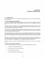
PREFACE
This service manual provides the information needed to implement RA81 disk drive corrective maintenance procedures. This book was written for the needs of the repair technician servicing the RA81. The
contents of this manual include the following items:
•
The maintenance features of the drive and the related reference documentation for the RA81
subsystem.
•
Removal and replacement procedures.
•
Spindle drive belt tension adjustment.
•
Field service diagnostic terminal installation.
•
Drive-resident diagnostic usage.
•
Fault isolation procedures.
Installation procedures are not included in this manual, but may be found in the RA81 User Guide, Chapter 2.
IX
CHAPTER 1
GENERAL INFORMATION
1.1 INTRODUCTION
This chapter describes the RA81, its maintenance phillosophy and features, and lists the related documentation for the drive.
1.2 RA81 DISK DRIVE DESCRIPTION
The RA81 is a random-accessed, moving-head disk drive. It can store up to 456 megabytes of data on a
non-removable head/disk assembly. The basic design of the RA81 is similar to the RM80 and RA80 disk
drives.
The RA81 connects to a controller by way of the Standard Disk Interconnect (SDI) bus. The drive can be
connected in a dual-port arrangement to two controllers. Each controller in turn communicates to the host
CPU using Mass Storage Control Protocol (MSCP).
The RA81 has a power supply, cooling system, and drive logic contained within the drive chassis. The drive
logic contains extensive self-diagnosis capabilities. Two microprocessors share the control of the diagnostic
as well as the operating modes of the drive.
Drive-resident diagnostics are executed by use of an external terminal. This terminal can be any 300 baud,
EIA-compatible terminal with an ASCII interface. A portable, hand-held field service terminal is provided
with every controlled distribution (CD) kit. Operating instructions are provided in this manual (Appendix
J).
The HDA contains four platters and 14 read/write heads. An additional read-only head is positioned over a
surface that contains servo information. This servo information is for coarse positioning of the read/write
heads. Fine positioning is accomplished by servo information embedded in the data areas.
The HDA contains seven surfaces for reading/recording data. Each surface in turn, has two read/write
heads.
1.3 RA81 MAINTENANCE FEATURES
The RA81 has been designed for ease of service and has the following maintenance features.
•
Easy access to all field replaceable parts
•
Fault reporting by the operator control panel
•
FRU callout in the error report
•
Drive resident diagnostic and utility routint!s
1-1
•
Read/write diagnostic tracks
•
No head alignments
•
No electrical adjustments
•
No preventive maintenance procedures
1.4 RA81 MAINTENANCE PHILOSOPHY
The repair strategy for the RAS1 is module replacement. Diagnostics are contained in the drive microcode.
The field service engineer uses the results of the diagnostics to isolate fault conditions to the field replaceable unit (FRU) level. In addition to the drive-resident diagnostics, system-resident diagnostics are available to support and verify corrective maintenance decisions.
1.5 RA81 RELATED DOCUMENTATION
The RAS1 related documentation is separated into two groups. The following documentation is available
from Printing and Circulation Services.
•
RA81 Disk Drive User Guide (EK-ORAS1-UG)
•
RA81 Disk Drive Illustrated Parts Breakdown (EK-ORASl-IP)
The following documentation is available from the Software Distribution Center.
•
RA81 Field Maintenance Print Set (MP-01359)
•
RA81 Disk Drive Maintenance Guide (AA-MS79A-TC)
•
Maintenance Guide Binder (AV-L9S0A-TK)
•
UDA50 Maintenance Documentation Kit (QP904-GZ)-This kit includes a binder, the UDA50
Maintenance Guide and the available drive maintenance guides that operate on the UDA50.
Non-DIGITAL customers must order manuals through the Accessories and Supplies Group (A & SG). The
address for A & SG is:
DIGITAL EQUIPMENT CORPORATION
Attn: Circulation Departn1ent, RQ/WS
460 Amherst Street
Nashua, NH 03063.
1-2
REMOV AL
Al~D
CHAPTER 2
REPLACEMENT PROCEDURES
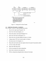
2.1 INTRODUCTION
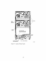
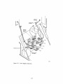
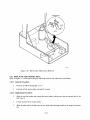
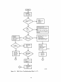
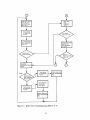
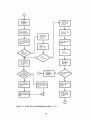
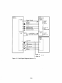
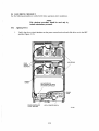
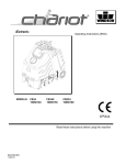
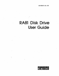
This chapter describes the RA81 parts removal and replacement procedures. The following sequence describes the proper removal procedure for RA81 parts.
1.
Find the part to be removed on the sequential flow diagram (Figure 2-1).
2.
Follow the path to the top of the diagram.
3.
Start by removing the first item in the path that the flow line passes through.
4.
Continue down the flow line removing parts until the wanted part is reached.
Paragraph numbers help in the location of each removal procedure. Parts that can be removed directly are
not shown on the diagram. Unless otherwise indicated, parts replacement is the reverse of the removal
procedure.
WARNING
Hazardous voltages are present inside this equipment. Installation and servidng should be performed
by a qualified and trained service representative.
Bodily injury or equipment damage may result from
improper servicing.
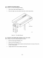
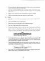
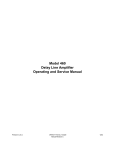
2.2 REMOVING POWER FROM THE DISK DRIVE
Before replacing assemblies in the RA81, the disk should be stopped and the ac line power removed. Figure
2-2 shows the power controls for the RA81 and power controller (H874).
2.2.1 Removing Power from the Drive Internal Asslemblies
To remove power from everything but the power supply, switch off CB 1 at the back of the RA81.
2.2.2 Removing Power from the H7660A or B Power Supply
To remove power from the H7660A or B power supply, unplug the ac cord from the receptacle on the
power control unit at the bottom of the RA81 cabinet.
2-1
RAISE LOGIC ACCESS COVER (2.7)
L-SERVO MODULE (2.8)
LPERSONALITY MODULE (2.8)
LMICROPROCESSOR MODULE (2.9)
RAISE DRIVE LOGIC CHASSIS (2.10)
LOGIC DC HARNESS ASSEMBLY (2.11)
FRONT BEZEL FANS (2.12)
READ/WRITE MODULE (2.13)
FRONT BEZEL (2.13) lBRUSH GROUND SPRING (2.14)
LOPERATOR CONTROL PANEL AND CABLE (2.16)
LLOGIC AC HARNESS ASSEMBLY (2.17)
DRIVE PEER SUPPLY (2.18)
REAR POWER SUPPLY FAN (2.19)
FORWARD POWER SUPPLY FAN (2.19)
HEAD DISK ASSEMBLY (2.13)
SPEED SENSOR (2.20)
HDA TEMPERATURE SENSOR (2.20)
E
BELT TENSION MICROSWITCH (2.21)
SPINDLE BELT (2.22)
t
MOTOR/BRAKE ASSEMBLY (2.23)
. LMOTOR ACTUATOR ASSEMBLY (2.24)
WING PIVOT ASSEMBLY (2.25)
Figure 2-1
CZ-0798
Parts Removal and Replacement Diagram
2-2
DISK DRIVES
DRIVE
CIRCUIT
BREAKERS
POWER
CORDS
AC OUTLETS FOR
DRIVE POWER ON FRONT
OF POWER CONTROLLER
POWER
LAMP
POWER CONTROLLER
CIRCUIT BREAKER
LOCAL/REMOTE SWITCH
CZ-0766
Figure 2-2 Location of Power Controls
2-3
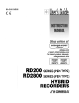
2.3 REMOVING THE BACK CABINET DOOR AND END PANELS
Refer to Figures 2-3 and 2-4 while performing this procedure.
l.
Unlock the back door with a 5/32" hex key wrench.
2.
Disconnect the green/yellow striped ground wire using a phillips screwdriver.
3.
Unlatch the back door and lift off the frame assembly.
4.
Remove the two end panel locks by loosening the screws and then lifting the locks off the panels.
5.
Lift the end panels up and away from the cabinet.
6.
Remove the green/yellow ground wire from the cabinet and set the end panel aside.
TOP KEY BUTTONS
REMOVE CENTER SCREW
Figure 2-3
End Panel Removal
2-4
CZ·0774
:~KR ~~ --
1
--
GREEN AI\JD
YELLOW
GROUND WIRE
-I}
PULL
DO~
LATCH
-
CZ-0792
Figure 2-4 Back Door Removal
2-5
1.
Remove the switch covers by prying against the recessed side of the cover with a screwdriver.
NOTE
Place paper or other material between the bezel and
the screwdriver to prevent chipping the paint on the
drive cabinet.
LAMP
PULL OUT METAL SLIDE
TO EJECT THE LAMP
CZ-0636
Figure 2-5
Control Panel Light and Switch Cover Removal
2-6
2.
Reach into the switch opening and pull on the metal slide to remove each light. The light will
pull out with the slide.
3.
With the flat section of the new bulb in a horizontal position, push the bulb into the socket as far
as it will go.
4.
Replace the cover by pushing it into the switch opening as far as it will go. Use only a small
amount of pressure to position the cover into place.
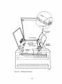
2.5 REPLACING THE AIR FILTER
Refer to Figure 2-6 while performing this procedure.
1.
Push up on the door latch of the front bezel and lower the door to a horizontal position.
2.
Remove the foam air filter by pulling down on the top half of the filter and then lifting it out of
the drive.
OPERATOR
CONTROL
PANEL
Figure 2-6
Air Filter Removal
2-7
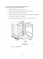
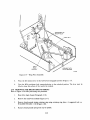
2.6 EXTENDING AND RETRACTING THE DRIVE ON SLIDES
To replace FR Us on drives mounted on slides, follow the procedures in the next two paragraphs.
2.6.1
Extending the Drive on its Slides
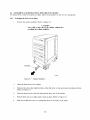
1.
Pull out the cabinet stabilizer. Refer to Figure 2-7.
CAUTION
Never slide a drive out of the cabinet without first
extending the cabinet stabilizer.
CZ-0753
Figure 2-7
Cabinet Stabilizer
2.
Open the back door of the cabinet.
3.
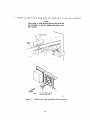
Remove the screw that holds the back of the disk drive to the electrostatic discharge bracket.
Refer to Figure 2-8.
4.
Push the detent latch to the left and push the drive out of the cabinet.
5.
Pull the drive out on its slides until it locks in place. Refer to Figure 2-9.
6.
Push up on slide lock arm A to extend the drive to the limits of the slides.
2-8
DETENT
LATCH
/
ELECTROSTATIC
DISCHARGE
BRACKET
LEFT REAR OF
DISK DRIVE
NOTE
1. REMOVE POWER SUPPLY SCREW TO
SLIDE DRIVE FORWARD. REPLACE SCREW
THROUGH BRACKET EACH TIME THE DRIVE
IS SLID BACK INTO CABINET.
CZ-0586
Figure 2-8
Electrostatic: Discharge Bracket
DRIVE
CABINET
DISK
DRIVE
SLIDE
ASSEMBLY
PHILLIPS HEAD
SEM SCREWS
8-:32
x
5/16
(2 EACH SIDE)
Figure 2-9 Extending the Chassis Slides
2-9
CZ-0754
2.6.2
Sliding the Drive Back into the Cabinet
1.
Push in on slide lock arm B and slide the drive into the cabinet.
2.
Check that the detent latch at the back of the cabinet has locked the drive into place.
3.
Replace the screw on the power supply through the electrostatic discharge bracket.
4.
Close the back door of the cabinet.
2.7 RAISING THE LOGIC ACCESS COVER
Refer to Figure 2-10 while performing this procedure.
I.
Turn the logic access cover lock 90 degrees counterclockwise while placing pressure on the
cover. Cover will pop up slightly, once the cover latch is released.
2.
Raise the logic access cover.
LOGIC ACCESS COVER
LOGIC ACCESS
COVER LOCK
/
CZ-0739
Figure 2-10 Access to the Inside of the Drive
2-10
2.8 REMOVING THE SERVO AND PERSONALITY MODULES
Refer to Figure 2-11 while performing this procedure.
1.
Raise the logic access cover (Paragraph 2.7).
2.
Unplug all module cables.
NOTE
Do not cut the tie wraps on the SDI cables. Instead,
remove the nylon nut and unplug the connector with
the tie wrap attached.
3.
Lift module(s) out of the chassis.
PERSONALITY
MODULE
CZ-OI61
Figure 2-11
Servo and Personality Module Removal
2-11
2.9 REMOVING THE MICROPROCESSOR MODULE
Refer to Figure 2-12 while performing this procedure.
1.
Raise the logic access cover (Paragraph 2.7).
2.
Pivot the servo and personality modules up to gain access to the microprocessor module.
3.
Remove servo and personality modules (Paragraph 2.8).
4.
Unplug all cables to the microprocessor module.
5.
Pull up on the five push pins holding the module to the chassis.
6.
Lift the microprocessor module out of the logic chassis.
MICROPROCESSOR
MODULE
CZ-0348
Figure 2-12
Microprocessor Module Removal
2-12
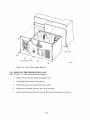
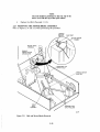
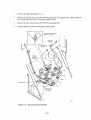
2.10 RAISING THE DRIVE LOGIC CHASSIS
Refer to Figures 2-10 and 2-13 while performing this procedure.
l.
Push the logic chassis release latch with a screwdriver.
2.
Lift the drive logic chassis to a completely raised position (Figure 2-13).
READ/WRITE
MODULE
HDA
BELT
TENSION
LEVER
RELEASED POSITION
CZ-0793
Figure 2-13
Lower Chassis Part Locations
2-13
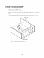
2. t t
REMOVING THE DC POWER HARNESS ASSEMBLY
Refer to Figures 2-14 and 2-15 while performing this procedure.
1.
Raise the logic access cover (Paragraph 2.7).
2.
Remove the servo, personality and microprocessor modules (Paragraphs 2.8 and 2.9).
3.
Remove the feedthrough bracket screws.
4.
Remove the two screws holding the DC power harness.
5.
Raise the drive logic chassis (Paragraph 2.10).
6.
Unplug P701, P702 and P703 connectors.
7.
Remove the DC power harness.
TOP LOGIC CHASSIS
FEEDTHROUGH
BRACKET
RUBBER GROMMET
DC POWER HARNESS
CZ-0163
Figure 2-14
DC Power Harness Removal
2-14
LOGIC AC
HARNESS ~
SCREWAN~
WASHER
~
CZ-0628
Figure 2-1 5 Power Supp1y Connectors
2-15
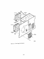
2.12 REMOVING THE FRONT BEZEL FANS
Refer to Figure 2-16 while performing this procedure.
1.
Raise the drive logic chassis (Paragraph 2.11).
2.
Remove the two screws holding the fan that is to be removed.
3.
Slide the fan out of the chassis and remove the quick-connectors.
4.
Remove the four screws and nuts that hold the ian on its bracket.
I
I
~ SJ
AIRFLOW
",/ ~ '" - ~- :~
TWO PHILLIPS
SCREWS
HEA~
~
I
BRACKET
~ ~~ FOUR KEP NUTS AND FOUR SCREWS
HOLD THE FAN ON ITS BRACKET
CZ-0629
Figure 2-16
Front Bezel Fan Removal
2-16
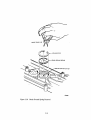
2.13 REPLACING THE HDA AND THE READ/WRITE MODULE
Refer to Figures 2-17 and 2-18 while performing the following removal and replacement procedures.
2.13.1
HDA Removal
1.
Raise the drive logic chassis (Paragraph 2.10).
2.
Unplug connector PS02 from the read/write module.
NOlTE
If only the read/write module is being replaced, go
to step 9.
3.
Unplug connectors P602 and P603 from the HDA preamplifier module.
4.
Place the belt tension lever into the release position.
S.
Remove the four HDA retaining nuts.
6.
Place the positioner lock into the LOCK position (Figure 2-18). The lever must be lifted slightly
to clear the surface of the R/W module.
CAUTION
If the above step is not pelrformed, the HDA may be
damaged.
7.
Remove the HDA from the drive by lifting it from diagonally opposite corners. The HDA
weighs approximately 3S pounds.
8.
Place the HDA on a level surface in the vertical position only. Feet are provided on the front
cover of the HDA for this purpose.
CAUTION
Do not place the HDA in al horizontal position (on its
pulley). The speed and temperature transducers
mounted on the bottom of the HDA could be damaged.
9.
If the read/write module is to be removed:
l.
Unplug connectors PSOI and PS03 from the read/write module.
2.
Remove the four screws holding the read/write module to the HDA.
NOlTE
If an HDA is being repla.~ed, follow the procedures
outlined in paragraphs 5.3.5 through 5.3.8. This ensures proper checkout of the new HDA and shipping
of the old.
2-17
READ/WRITE
MODULE
HDA
BELT
TENSION
LEVER
READ PREAMPLIFIER
MODULE
HDA RETAINING
NUTS (4)
CZ-0797
Figure 2,·17
HDA and Read/Write Module Removal
2-18
HAND
POSITIONS
FOR
REMOVAL
CZ-8021
Figure 2-18
2.13.2
1.
HDA Positioner Lock
Replacement Procedures
Check that the drive belt is centered on the motor pulley. The other end of the belt should be
even with the top of the nylon rollers on the wing pivot assembly (see Figure 2-19).
CAUTION
If the drive belt is not ali~~ned correctly, damage to
the HDA, drive belt or nylon roller may result.
2.
Lift the HDA by grasping diagonally opposite corners and lower it over the four mounting bolts.
3.
Replace the four nuts and washers on the HDA.
4.
Connect P602 and P603 to the read prearnplifier module on the front of the HDA.
S.
Install the read/write module on top of the HDA if it was removed, or if this is a new HDA.
6.
Connect PSO 1, PS02 and PS03 to the read/write module.
7.
Connect P601 to the HDA read preamplifier module if it was removed.
2-19
Figure 2-19 Wing Pivot Assembly
8.
Place the belt tension lever in the full forward (engaged) position (Figure 2-17).
9.
Turn the HOA positioner lock counterclockwise to the unlocked position. The lever must be
lifted to clear the surface of the read/write module.
2.14 REMOVING THE BRUSH GROUND SPRING
Refer to Figure 2-20 while performing this procedure.
1.
Raise drive logic chassis (Paragraph 2.10).
2.
Remove the read/write module (Figure 2-17).
3.
Remove brush ground spring retaining ring using retaining ring pliers. A suggested tool is a
W ALOES TRUARC 1120 (Figure 2-20).
4.
Remove brush ground spring from top of spindle.
2-20
WALDES TRUARC 1120
GROUND CONTACT ON HDA
CZ·0804
Figure 2-20
Brush Ground S pnng
. RI;!ffioval
2-21
2.15 REMOVING THE FRONT BEZEL
Refer to Figure 2-21 while performing this procedure.
1.
Raise the drive logic chassis (Paragraph 2.10).
2.
Remove the eight screws that hold the front bezel to the drive logic chassis.
FRONT BEZEL
CZ-0626
Figure 2-21
Front Bezel Removal
2.16 REMOVING THE OPERATOR CONTROL PANEL AND CABLE
Refer to Figures 2-22 and 2-23 while performing this procedure.
1.
Raise drive logic chassis (Paragraph 2.10).
2.
Remove front bezel (Paragraph 2.15).
3.
Remove the two screws that hold the operator control panel bracket to the chassis. These screws
are under the logic chassis.
4.
Unplug connector PI0l from the operator control panel.
2-22
Figure 2-22 Operator Control Panel Removal
NOTE
When installing a new operator control panel, the
shunts on the module that indicate the drive serial
number must be cut. Also, a DIP switch that determines the revision level of the drive to the software
must be configured. Figure :~- 23 shows the shunt and
switch configuration.
2-23
DIP
SHUNT
DIP
SWITCH
:~F[[[[ill
u
DIP SHUNT
DIP SHUNT
W]]J I~ ~ 8888881
U 'I 1'6'5
1
8
182 22~ g~ 21
7
0J
DISK DRIVE SER;:;'''''L-N-U-M-S-E-R _ _ _ _.-J
III
-
RESERVED
PLANT CODE EXPANSION
,.....- - - - - - - - - HARDWARE REVISION LEVEL
NOTES
1. WHEN REPLACING THE OPERATOR CONTROL
PANEL, THE SHUNTS SHOULD BE SET ON
THE NEW PANEL TO RESEMBLE THE
OLD PANEL. BREAK EACH SHUNT BY
PUSHING DOWN ON IT WITH A SMALL
SCREWDRIVER. EACH SHUNT LEFT
INTACT REPRESENTS A LOGICAL O.
A BROKEN SHUNT REPRESENTS A
LOGICAL 1.
Figure 2-23
CZ-0641
Setting the Drive Serial Number
2.17 REMOVING THE LOGIC AC HARNESS
Refer to Figures 2-24 and 2-25 while performing this procedure.
1_
Raise the drive logic chassis (Paragraph 2.10).
2.
Remove the front bezel (Paragraph 2.15).
3.
Remove the operator control panel (Paragraph 2.16).
4.
Remove the front bezel fans (Paragraph 2.12).
5.
Remove the screw and washer holding the harness to the chassis.
6.
Unplug connector P705 from the power supply to the harness.
7.
Raise logic access cover (Paragraph 2.7).
8.
Remove the wires from the motor start capacitor (found to the right of the personality module).
9.
Cut the ac harness cable clamps.
10.
Remove the cable clamp screws.
11.
Pull the two grommets from their retaining holes.
12.
Remove the ac harness from the chassis front.
13.
Pull the ac harness down through the hole in the back of the chassis.
2-24
CHASSIS CUT OUT
CZ·0789
Figure 2-24
Drive Power Supply
Conm~ctors
2-25
P705
LOGIC AC
HARNESS ASSEMBLY
CZ-0174
Figure 2-25
Logic AC Harness Assembly Removal
2.18 REMOVING THE DRIVE POWER SUPPLY
Refer to Figures 2-24 and 2-26 while performing this procedure.
1.
Unplug the power supply AC line cord from the power controller at the base of the cabinet.
2.
Raise the drive logic chassis (Paragraph 2.10).
3.
Unplug connectors P701, P702, P703, P704 and P705 from the drive power supply.
4.
Remove the ground wire from the top ground terminal found on the front of the power supply.
5.
Remove any cable clamps or cable ties from the ac power cord.
6.
Remove the six 1/4" hex-head screws from the back of the power supply.
7.
Pull the power supply out of the back of the drive, routing the two fan wires through the chassis
cutout.
NOTE
The power supply weighs approximately 35 pounds.
2-26
/
/
CZ-0783
Figure 2-26
Drive Power Supply Removal
:t19 REMOVING THE POWER SUPPLY FANS
Refer to Figure 2-27 while performing this procedure:.
1.
Remove the drive power supply (Paragraph 2.18).
2.
Unplug the black connector from the fan.
3.
Remove the four screws that hold the fan jin place.
4.
Remove the fan guard if the rear fan is to be removed.
5.
Remove the four tinnerman nuts from the old fan and mount them on the new.
2··27
CZ·0803
Figure 2-27
Power Supply Fan Removal
2-28
2.20 REMOVING THE HDA SPEED AND TEIVIPERATURE SENSORS
Refer to Figures 2-28 and 2-29 while performing this procedure.
1.
Raise the drive logic chassis (Paragraph 2.10).
CAUTION
Place the HDA positioner lock in the locked position
before removing the HDA
2.
Remove the HDA (Paragraph 2.13).
3.
Unplug connector P501 from the read/write module.
4.
Remove the quick-connect terminals from the temperature sensor.
5.
Remove the temperature sensor by turning it counterclockwise.
6.
Remove the two screws that hold the speed transducer on the HDA.
7.
Remove the speed transducer assembly.
PLASTIC BUl.KHEAD FEET
Figure 2-28
HDA and Read/\Vrite Module
2··29
CZ-0799
PULLEY
TIMING DISK
TEMPERATURE
SENSOR
SPEED TRANSDUCER
P501Y
~
PLASTIC BULKHEAD FEET
Figure 2-29
CZ-0088
HDA Speed and Temperature Sensor
2.21 REMOVING THE BELT TENSION MICROSWITCH
Refer to Figure 2-30 while performing this procedure.
1.
Remove the HDA (Paragraph 2.13.1).
2.
Remove the screw that holds the belt tension switch to the side of the chassis.
3.
Remove the microswitch from its bracket.
4.
Unplug the blue and white quick-connect terminals from the microswitch. Replace as shown in
Figure 2-30.
2-30
MICROSWITCH
CZ-0185
Figure 2-30
~~.22
Belt Tension Microswitch Removal
REPLACING THE SPINDLE BELT
Refer to Figure 2-31 while performing the following removal and replacement procedures.
~~.22.1
Removal Procedures
1.
Remove the HDA (Paragraph 2.13.1)
2.
Lift belt off the motor pulley and pull it forward.
2.22.2 Replacement Procedures
1.
Slide the new belt under and around the motor pulley making sure that the smooth side of the
belt faces in.
2.
Center the belt on the motor pulley.
3.
Slide the other end of the belt over the two nylon roller bearings found on the wing pivot assembly.
2-31
NOTE
The belt should be positioned so that the top of the
belt is even with the top of the nylon rollers.
4.
Replace the HDA (Pararaph 2.13.2).
2.23 REMOVING THE MOTOR/BRAKE ASSEMBLY
Refer to Figures 2-31 and 2-32 while performing this procedure.
L-SHAPED
SPINDLE MOTOR
DRIVE BELT
CZ-0791
Figure 2-31
Belt and Motor/Brake Removal
2-32
1.
Remove the HDA (Paragraph 2.13.1).
2.
Remove the two hex nuts on the drive motor ground wire. The ground wire is green/yellow in
color and grounds the motor to the power supply chassis.
3.
Remove the drive motor ground wire frOIn the grounding bolt.
4.
Unplug connector P704 from the power supply chassis.
REMOVE GROUND WIRE
FROM TOP SCREW
I,
;,
CHASSIS CUT OUT
CZ-0633
Figure 2-32
Removing the Ground Wire
2-33
5.
Slide the spindle motor drive belt off the wing pivot assembly and the motor pulley (Figure
2-31).
6.
Remove the drive motor tension spring. A pair of long-nosed pliers should be used to remove the
spring from under the L-shaped bracket.
7.
Lift the motor/brake assembly off the pivot posts.
2.24 REMOVING THE MOTOR ACTUATOR ASSEMBLY
Refer to Figures 2-33 and 2-34 while performing this procedure.
1.
Remove the HDA (Paragraph 2.13.1).
2.
Remove the motor/brake assembly (Paragraph 2.23).
3.
Remove the four kepnuts and washers that hold the lower air baffle in place.
4.
Remove the baffle.
Figure 2-33
Lower Air Baffle Removal
2-34
5.
Remove the three retaining rings and washers that hold the motor actuator assembly in place.
6.
Remove the screw and beveled washer that hold the belt tension lever and lock spring to the
chassis.
NOTE
When being replaced, the hollow side of the beveled
washer should face the 100~king spring.
7.
Slide the motor actuator assembly off the chassis sidewall studs.
8.
Remove the motor actuator assembly through the front of the drive.
CHASSIS
SIDEWALL
STUDS
BELT TENSION
LEVER
NYLON
WASHER
NYLON
WASHER
\
--'\~
~
REMOVE
RETAINING
RINGS
CZ-0189
Figure 2-34 Motor Actuator Assembly Removal
2-35
2.25 REMOVING THE WING PIVOT ASSEMBLY
Refer to Figure 2-35 while performing this procedure.
1.
Remove the HDA (Paragraph 2.13.1).
2.
Lift the belt off the wing pivot assembly.
3.
Remoye the two screws, three retaining rings and washers that hold the wing pivot assembly in
place.
4.
Lift the wing pivot assembly off the locating studs and slide it under the lower air baffle.
LOWER AIR BAFFLE
Cl-0190
Figure 2-35
Wing Pivot Assembly Removal
2-36
CHAPTER 3
ADJUSTMENTS
3.1
INTRODUCTION
This chapter describes the drive belt tension adjustn1ent procedure for the RA81. This is the only field
adjustment that can be performed on this drive.
3.2
BELT TENSION ADJUSTMENT
The tension on the spindle drive belt should be checked when replacing the motor, motor pulley, drive belt
or HDA. Belt tension should also be checked during every service call because the drive belt stretches
slightly with use. To check or adjust belt tension, perform the following procedures.
1.
Place the RUN switch on the operator control panel in the OUT position to stop the spindle
drive motor.
2.
Raise the drive logic chassis.
3.
Find the belt tension adjustment screw and brass-colored slider shown in Figure 3-1.
BELT
TENSION
ADJUSTMENT
SCREW
MOTOR/BRAKE
ASSEMBLY
'"
HDA
Figure 3-1
Belt Tension Adjustment Screw
3-1
CZ-0790
4.
The brass-colored slider should be even with the belt tension adjustment indicator (Figure 3-2).
[f not, an adjustment is necessary.
NOTE
Before performing the adjustment, make sure that
the power is turned off at the ac power controller
5.
Locate the belt tension adjustment locking nut using Figure 3-1.
6.
Loosen the locking nut and adjust the belt tension screw until the brass-colored slider is even
with the adjustment indicator. Turn the screw clockwise to move the slider forward.
7.
Tighten the locking nut after the adjustment is made.
8.
Restore ac power to the drive and apply power to the spindle drive motor by pushing the RUN
switch to the IN position.
BRASS -
COLORED SLIDER
SLIDER SHOULD
BE EVEN WITH
OUTSIDE EDGE
OF INDICATOR
CZ-0782
3-2
CHAPTER 4
DRIVE-RESIDENT DIAGNOSTICS
4.1
INTRODUCTION
This chapter describes RA8! drive-resident diagnostk capabilities. Installation of the field service diagnostic terminal is described along with the various diagnostic commands. Diagnostic test descriptions are in
Appendix D.
4.2 FUNCTIONAL AND DIAGNOSTIC FIRM\V ARE
Functional firmware and diagnostic firmware are two distinct software modules in the RA8!. The functional firmware controls the spin-up cycle, seek and recalibrate commands. The functional firmware also
performs fault monitoring and interface handshaking operations.
The drive is operating in an on-line mode when the functional firmware is controlling the drive operations.
The drive is operating in diagnostic monitor mode when it is operating under control of the diagnostic
firmware. The diagnostic firmware controls all drive-resident tests and utility programs. Paragraph 4.3.3
describes how to enter diagnostic monitor mode.
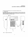
4.3 THE DIAGNOSTIC TERMINAL
A field service diagnostic terminal (Figure 4-1) is stocked with every spares kit. It utilizes a standard ASCII
keyboard and an RS232 interface. Any EIA-compatible terminal set at 300 baud can be used to communicate with the drive (the drive logic defaults to 300 baud). A variety of drive diagnostic tests can be run
using the terminal (paragraphs 4.4 and 4.5). The following paragraphs desribe the installation of the terminal.
4.3.1
Powering Up the Drive
Ensure the RUN/STOP switch and both port select switches are in the OUT position. Apply power to the
drive. At this time the drive runs a power-up test sequence. The sequence consists of various hardcore tests
with static master logic and servo tests. Appendix B lists the various drive test sequences. The front panel
lights turn on when the hardcore tests are being executed. Successful completion of the power-up sequence
is indicated by the front panel lights going off in about 3-4 seconds. If any are left on, all or part of the
sequence failed. Appendix F of this manual contains the front panel troubleshooting information.
4.3.2 Idle Loop Test
The drive logic proceeds to execute another test sequence called the idle loop test sequence. This test sequence is started approximately 30 seconds following the successful completion of the hardcore test sequence (provided the port select switches are in the OUT position). The idle loop test takes about 30
seconds to run. The microprocessor LEDs display a hexadecimal E7 during the execution of the idle loop
test sequence. Errors are reported through the front panel indicators. (See Appendix F for troubleshooting.)
The idle loop test sequence repeats as long as the drive switches are not changed or diagnostic mode is not
entered. The idle loop test sequence may halt if a front-panel switch is pushed.
The following paragraphs describe the action of the idle loop testing when a switch is pushed.
4-1
•
Write Protect - The drive logic stops testing and lights the write protect light. The drive then
becomes READY. After a 10 to 20 second delay, the READY light goes out and the idle loop
testing is resumed.
•
Fault - This switch is ignored during idle loop testing.
•
Port Select Switches - If either or both of these switches are pushed, idle loop testing stops and
the drive logic exits monitor mode.
•
Run (Spun Down) - If the drive is spun down when this button is pushed, the current idle loop
test completes. Following completion, the HDA is spun up. Idle loop testing resumes following
the spin-up test sequence.
•
Run (Spun Up) - If the drive is spun up when this button is pushed, the current idle loop test
completes. Following completion, the HDA is spun down. Idle loop testing resumes following a
delay of 10 to 20 seconds.
DISPLAY SCROLL
SWITCH
"'oliloDIilD
EQUIPMENT
W ~
IioI CORPORATION
CZ-0768
Figure 4-1
Field Service Diagnostic Terminal
4.3.3 Installing the Terminal on an RA8l Disk Drive
To use the diagnostic terminal, diagnostic monitor mode must be entered. The drive does not respond to the
keyboard until both port select switches on the drive are in the OUT position. If either switch is IN, the
drive is in the available state awaiting a command from the controller.
4-2
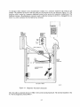
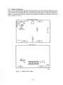
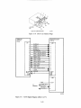
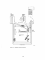
An interface cable connects to the microprocessor lTIodule via a connector located in the center of the
module. The connector is keyed so that the cable may be inserted in only one direction (Figure 4-2). The
interface cable is routed to a connector bulkhead located on the motor start capacitor compartment. The
bulkhead contains a D-subminiature connector used to cable the terminal to the nrive. Alongside the connector is a power connector for the field service tern1inal.
RS232
DIAGNOSTIC
TERMINAL
CONNECTOR
DIAGNOSTIC
TERMINAL
POWER
CONNECTOR
e
~
::
PIN 1
GND
"
"
"
"
P306
o
0 o0 ODD DOD DOD DO 0000
MOTOR
START
CAPACITOR
P307
MICROPROCESSOR
MODULE
TOP VIEW OF DRIVE
CZ-0773
Figure 4-2
Diagnostic Terminal Connections
Once the cable is connected, key in a CTRL C (TC) on the terminal keyboard. The terminal responds to the
TC with the diagnostic prompt RA81>.
4-3
NOTE
If the field service diagnostic terminal is cabled to
the drive during the execution of the drive idle loop
tests, the prompt is not displayed until the testing is
completed. During the execution of the idle loop test
sequence, the terminal displays the following:
%RA81-COMPLETED TEST: SU8TEST:xx
Next, key in a continue (CONT) on the terminal keyboard. This disables the automatic X-On, X-Off feature allowing the testing to be continuous.
Upon display of the diagnostic prompt, user diagnostic testing may be run by keying in one of ten diagnostic commands. These commands are described in the following paragraphs.
4.4 DIAGNOSTIC COMMAND SELECTION
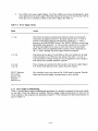
Table 4-1 lists the diagnostic commands and their abbreviations. The utility commands that are recognized
by the drive are described in Paragraph 4.5.
Table 4-1
Diagnostic Commands
Command Name
Abbreviation
Run
Run
Run
Run
Run
Run
Run
Run
Run
Run
RUNDIAG
RUN SEEK
RUNRECA
RUN READ
RUNSERV
RUNINTE
RUN ALTE
RUN RAND
RUNINCR
RUN DIAG TEST=xx
Diagnostics
Seek
Recalibrate
Read/Write
Servo
Interface
Alternate
Random
Incremental
Diagnostic Test = xx
Note that each of the commands may be abbreviated to the first four letters with the exception of RUN
DIAGNOSTIC TEST. In this command the word TEST=xx must be present in order to request that a
particular test be run. See Appendix C for the test selection list.
When any command is miskeyed, spelled wrong, or if the word RUN is not input first, the terminal responds with an audible tone and displays the following:
COMMAND NOT FOUND
4-4
4.4.1 Run Diag
This command may be used on two different occasions:
1.
When the drive has power applied but does not have the run switch pushed.
2.
When the drive has power applied but the run switch is pushed.
4.4.1.1 Spun Down - In this mode the terminal causes the drive logic to perform an entire drive checkout
sequence. The drive determines the test selection when in this mode. In this case the drive is spun down and
will run the appropriate series of subtests. Appendix B lists the tests run in this sequence and Appendix D
lists the test display fault codes.
As the drive test sequence progresses, the following responses are displayed by the terminal.
%RA81-COMPLETED TEST:DIAG SUBTEST:xx
%RA81-COMPLETED TEST:DIAG SUBTEST:xx
%RA81-COMPLETED TEST:DIAG SUBTEST:xx
RA8h
The above response shows that no errors were encoun1tered in any of the subtests executed. At the completion of the drive sequence test, the prompt returns and other tests may be requested. Error reporting is
covered in paragraph 4.6.
4.4.1.2 Spun Up - This mode causes a new sequence of tests to be run to check out areas of logic that
were not previously accessible. As the drive sequence progresses, the terminal displays a series of messages
iidentical to that of the spun-down sequence. The return of the prompt RA81> signifies the successful
completion of the sequence (in about 7 minutes). Other tests may be requested or the monitor mode may
be exited. Appendix B lists the tests run in this sequence, and Appendix D lists the test fault codes.
4.4.2 Run Reca
This command may be executed following a spinup cycle. The test causes the drive to position and keep the
read/write heads over track O. At the completion of the recalibration, the terminal displays the following:
%RA81-COMPLETED TEST:RECA SUBTEST:xx
RA8h
Any errors in the execution of the command are reported in the manner described in paragraph 4.6.
4-5
4.4.3 Run Seek
This command may be executed following a spin up cycle. The test causes a single seek to be performed to a
user-specified cylinder. Respond to the following prompts with a decimal cylinder address and a group
(R/W head) address. The maximum values are 1257 and 13, respectively.
ENDI NG CYLI NDER?
GROUP?
At the completion of the seek, the terminal displays the following:
COMPLETED
RA81 )
Errors in the execution of the seek are reported in the manner described in paragraph 4.6.
4.4.4 Run Read
This command may be executed following a spinup cycle. The test causes the drive to execute the entire
read/write test sequence. Appendix B lists the tests run in this sequence, and Appendix E lists the fault
display codes. At the completion of the sequence (about one and one-half minutes), the terminal returns
with the diagnostic prompt. Any errors in the execution of the sequence are reported in the manner described in paragraph 4.6. While the drive is running these tests, the terminal displays the following messages.
%RA81-COMPLETED TEST:READ SUBTEST:xx
%RA81-COMPLETED TEST:READ SUBTEST:xx
RA8h
4.4.5 Run Sen
This command may be executed following a spinup cycle. The test causes the drive to execute the entire
servo test sequence. Appendix B lists the tests run in this sequence and Appendix E lists the test fault
display codes. At the completion of the sequence (about four and one-half minutes), the terminal returns
with the diagnostic prompt. Any errors in the execution of the sequence are reported in the manner described in paragraph 4.6. While the drive is executing these tests, the terminal displays the following messages.
%RA81-COMPLETED TEST:SERV SUBTEST:xx
%RA81-COMPLETED TEST:SERV SUBTEST:xx
RA81)
4-6
4.4.6 Run Inte
This command causes the drive to execute the disk interface test. The drive must be spun down for this
sequence to be executed. At the completion of the test the terminal returns with the diagnostic prompt.
Any errors in the execution of the sequence are reported in the manner described in paragraph 4.6. While
the tests are being executed, the terminal displays th,e following message.
%RA81-COMPLETED TEST:IHTE SUBTEST:xx
RA8h
4.4.7 Run Alte
This command may be executed following a spinup cycle. The test causes the drive to perform alternating
seeks. The terminal requests the user to key in the: starting and ending cylinder addresses in decimal
(0-1257).
STARTIHG CYLIHDER?
EHDIHG CYLIHDER?
At the completion of the alternating seek test, the terminal displays the following:
%RA81-COMPLETED TEST:ALTE SUBTEST:xx
RA81>
Any errors in the execution of the seeks are reportedl in the manner described in paragraph 4.6.
4.4.8 Run Rand
This command may be executed following a spinup cycle. The test causes the drive to execute the random
seek test. The user does not specify the starting and ending cylinders. A random number table is used to
calculate the cylinder addresses used by the test. At the completion of the seeks, the terminal displays the
following:
%RA81-COMPLETED TEST:RAHD SUBTEST:xx
RA8h
Any errors in the execution of the seeks are reported in the manner described in paragraph 4.6.
4-7
4.4.9 Run Incr
This cornmand may be executed following a spinup cycle. The test causes the drive to execute an incremental seek test. The terminal requests the user to specify the lower and upper cylinder addresses (0-1257
decimal). The drive then seeks between the lower address and the upper, incrementing the lower cylinder
address by one until the upper cylinder address is reached. Recalibrates are performed between each of the
seeks.
STARTING CYLINDER?
END ING CYLI NDER?
At the completion of the incremental seeks, the terminal displays the following:
%RA81-COMPLETED TEST:INCR SUBTEST:XX
RA81>
4.4.10 Run Diag Test=xx
This command enables the user to run the test specified by xx. Appendix 0 describes the tests that may be
requested with this command. If the test selection entered under the RUN DIAG/TEST=xx is not available or not defined on the RA81 drive, the terminal responds with the following display.
%RA81-TEST:DIAG SUBTEST:xx ERROR:EE UHIT:xx
%RA81-FRU-TEST HOT AVAILABLE
After executing the selected test, the terminal displays the following:
%RA81-COMPLETED TEST:DIAG SUBTEST:xx
NOTE
A portion of the drive-resident tests may be run under control of the subsystem diagnostics. Appendix
C, Table C-l, lists the tests and test select codes that
may be requested with the host-resident diagnostics.
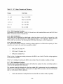
4.5 DIAGNOSTIC MONITOR UTILITY COMMANDS
Table 4-2 lists the utility commands for the diagnostic monitor. The paragraphs that follow describe each
of these commands.
4-8
Table 4-2
Diagnostic Monitor Utility Commands
Command Name
Abbreviation
Help
Set Diagnostic Loop xxxx
Set Terminal Speed=xxxx
Show Radix
Show Version
Show Device
Show Terminal Speed
Show Diagnostic Loop
Show Diagnostic Faults
Show Diagnostic Status xxxx
Show Diagnostic Memory xxxx = aaaa
Exit
HELP
SET DIAG LOOP xxxx
SET TERM SPEED = XXXX
SHOWRADI
SHOWVERS
SHOWDEVI
SHOW TERM SPEED
SHOW DIAG LOOP
SHOW DIAG FAUL
SHOW DIAG STAT xxxx
SHOW DIAG MEMO xxxx=aaaa
EXIT
4.5.1 Help
This command causes the terminal to display a list of all the possible diagnostic and utility commands.
4.5.2 Set Diag Loop xxxx
This command causes the drive to run the desired test (input with the RUN DIAG TEST=xx command) in
one of three loop modes available. The user specifies the type of diagnostic loop by inputting one of the
following in the xxxx field.
4.5.2.1 On - Typing this word in the xxxx field causes the diagnostic subtest to loop until a CTRL C (lC)
is input.
4.5.2.2
Off - Typing this word in the xxxx field causes the drive to run the diagnostic once and then stop.
NOTE
Off is the default if no otiller loop mode is set. If a
loop mode is set, it stays in that mode for every test
executed until one of the following actions take
place:
1. The user specifies a new loop mode
2. The user exits the
enters it
di~lgnostic
monitor and re-
3. The user spins down the drive and then spins it
back up
4.5.2.3 Halt - Typing this word in the xxxx field causes the test to be run until an error is encountered.
At this point the testing stops, the error is reported, and the terminal display returns with the diagnostic
prompt.
4-9
4.5.3 Set Term Speed=xxxx
This command instructs the drive to change the baud rate to that specified by xxxx in the input sequence.
The terminal displays the following message if the rate asked for is not available.
SELECT 300 OR 1200 BAUD ONLY
The default baud rate for the drive logic is 300. The RA81 drive logic can also handle the 1200 baud rate.
The field service diagnostic terminal can only handle 300 baud. If 1200 baud is requested by the 300-baud
terminal, communications will be discontinued until the drive is powered down and then back up.
4.5.4 Show Radi
This command causes the diagnostic terminal to display the base of all numeric displays. The terminal
displays the following when this command is executed.
TEST SELECT CODES, MEMORY ADDRESS ENTRIES
AND MEMORY DUMPS ARE HEX.
ALL REV NUMBERS, UNIT ,SER AND CYLINDER
NUMBER ENTRIES ARE DECIMAL
4.5.5 Show Vers
This command causes the diagnostic terminal to display the microcode, hardware, and SDI versions of the
drive. The terminal displays the following when this command is executed.
MICROCODE REVISION:xxxx
HARDWARE REVISION:xxx
SDI REVISION:xxx
4.5.6 Show Devi
This command displays the drive serial and unit numbers. The terminal displays the following when this
command is executed.
DRIVE SERIAL :xxxxxxx
UNIT :xxx
4.5.7 Show Term Speed
This command causes the diagnostic terminal to display the baud rate the drive is presently using to communicate with the monitor.
4-10
4.5.8 Show Diag Loop
This command causes the diagnostic terminal to display the diagnostic loop mode the drive is presently in.
The terminal displays the following when this command is executed.
LOOP MODE IS (HALT ON ERROR or ON or OFF)
4.,5.9 Show Diag Faul
This command causes the diagnostic terminal to display the last 16 HEX error codes stored in memory.
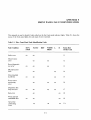
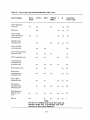
4.,5.10 Show Diag Stat xxx x
This command causes the diagnostic terminal to display up to 32 bytes of diagnostic status. The xxxx field
of the command specifies if the master (MAST) or slave (SLAV) processor RAMs will be displayed. Figure 4-3 shows the status results of the MAST RAN[ while Figure 4-4 shows the results of the SLAV
RAM.
Byte
xx
2 3 4 5 6 7 8 9 10
xx xx xx xx xx xx xx xx xx
\
)
~
11 12
13 14 15
xx xx
xx xx xx
V
Test Parameter
Save Area
Previous
Test
Se 1ect
Code
Figure 4-3
Extended
Results
Area
Results
Code
'-v-~
Miscellaneous
Test
Results
Previous
Error
Message
Address
Master RAM Status
NOTE
Bits 16 through 32 are not used.
4-11
Byte
23456 7
xx xx xx xx xx xx xx
8
xx
~
Slave
Command
Code
Diagnostic
Test
Parameters
Slave
Test
Results
Code
9 10 11 12 13 14 15
xx xx xx xx xx xx xx
\..
)
V
Miscellaneous
Diagnostic
Test
Results
Diagnostic
Test
Select
Code
Figure 4-4 Slave RAM Status
NOTE
Bytes 16 through 32 are not used.
NOTE
The display from a show command that reads from
the 8080/8085 microprocessor memory is in hexadecimal format. When requesting a specific memory
address the address must also be hexadecimal.
4.5.11 Show Diag Memo xxxx=aaaa
This command causes the diagnostic terminal to display 32 bytes of memory. The xxxx field of the command specifies the master (MAST) or slave (SLAVE) processor memory to be displayed. The aaaa field of
the command specifies the starting memory address to be displayed.
4.5.12 Exit
This command causes the drive to leave diagnostic monitor mode and enter into the drive off-line mode.
The drive then executes the drive idle loop sequence. Errors are reported through the front panel indicators.
The diagnostic prompt is not displayed while in this mode. The following will be shown on the terminal:
RA8h EXIT
EXITING THE MONITOR
4-12
4.6 DIAGNOSTIC ERROR REPORTS
If one of the tests fail, the terminal displays the following.
%RA81-TEST:aaaa SUBTEST:xx ERRoR:xx UNIT:xxx
%RA81-FRU- (an FRU callout list is printed here)
OR
%RA81-FRU- (instructions to fix the specific fault)
Depending on the loop mode that is set, the drive either continues running the sequence or halts on the
error. Paragraph 4.5.2 describes the loop mode settings. If the sequence is finished, or halts on an error, or
is taken out of loop mode, the diagnostic prompt is then displayed.
4.7 EXITING DIAGNOSTIC MONITOR MODE
The following three methods may be used to exit diagnostic monitor mode and make the drive available to
a controller:
1.
The command EXIT (described in paragraph 4.5.12) may be typed on terminal.
2.
A control Z (lZ) may be input. The terminal then displays the following message:
3.
The port select switches may be pushed. By pushing one or both of them, the diagnostic monitor
mode is automatically terminated. The foillowing message is displayed when exiting:
FRONT PANEL FUNCTION IN PROGRESS
RA81> EXITING THE MONITOR
4-13
CHAPTER 5
FAULT ISOLATION
5.1 INTRODUCTION
This chapter describes RA81 fault isolation procedures. It contains a description of the subsystem drive
error messages, troubleshooting tips and drive checkout procedures. Error code troubleshooting charts are
found in the appendices.
5.2 SUBSYSTEM ERROR MESSAGE INFORMATION
Subsystem error messages that are printed out in either the system error log or by the diagnostics contain
controller error as' well as specific drive error information. Figure 5-1 shows a sample error printout.
CZUDC HRD ERR 00044 ON UNIT 00 TST 004 SUB 000 PC:021044
DISK EXERCISER DM PC:5110 UDA AT 172150 DRIVE 032 RUNTIME 0:00:23
ENTIRE RCT AREA SEARCHED, COULD NOT FIND RBN TO REPLACE
LBN WITH HEADER COMPARE ERROR
SEARCHING FOR LBN: 900
CZUDC SFT ERR 00006 ON UNIT 00 TST 004 SUB 000 PC: 021044
DISK EXERCISER DM PC: 5324 UDA AT 172150 DRIVE 032 RUNTIME 0:00:37
TIMEOUT OF DRIVE DURING WRITE ATTEMPT
WRITE ATTEMPT RETRIES: 0
L/DBN NUMBER 5252
ACTUAL L/R/DBN 0
TRK 1 CRP 0 CYL 6
ORIGIN OF LAST SEEK WAS CYL 5 GROUP 1
REAL TIME DRIVE STATE 8001
STATUS: 0001 1100 0000 OAOO 0000 0613 1020
Figure 5-1 Subsystem Error Message Sample
5.2.1 Error Message Status Line Interpretation
The status line found in the error message (Figure 5-1) is the result of a get status command. The diagnostic
performs get status commands in the reporting of c:ertain error messages. Fourteen of a possible fifteen
status bytes are printed out by the error message routine as shown by the sample printout.
5-1
Figure 5-2 locates the RA81 drive-specific status bytes of the crror message. Bytes 2 through 8 are controller specific error/status information. Refer to the appropriate controller manual for a description of these
bytes. Note in Figure 5-2 that the first byte is not printed out. The first byte is a response code to the get
status command and is therefore not needed in the error report. The RA81 drive-specific status bytes are 9
through 15. Table 5-1 describes the contcnts of each RA81 status byte.
BYTE:
15 14
13 12
11 10
STATUS:
00 01
11 00
00 00
8
7 6
OA 00
00 00
9
5
1\
Y
4
06 13
3
2
10 20
y
CONTROLLER-SPECIFIC
STATUS
DRIVE-SPECIFIC
STATUS BYTES
CZ-0776
Figure 5-2
Drive-Specific Status Location
5.2.2 Real-Time Drive State Message Interpretation
The real-time drive state (RTDS) is represented by the line preceding the status in the error message. The
RTDS consists of four hexadecimal digits. In the sample printout found in Figure 5-1, the code is 8001.
Only four state bits within the four hexadecimal digits are of value to the field service engineer. The rest of
the bits are transitory and are therefore masked out before the RTDS message is printed. The location of
these four state bits within the hexadecimal code is shown in Figure 5-3. Paragraphs 5.2.2.1 through
5.2.2.4 describe the four RTDS state bits.
'15
14
13
HEX DIGIT 3
12
11
10
9
7
8
6
5
HEX DIGIT 1
HEX DIGIT 2
X = Do not care
condition
4
3
o
2
HEX DIGIT 0
CZ-0777
5.2.2.1
Read/write ready (R/W RDY) - The R/W RDY bit indicates that the drive is capable of performing a data transfer to or from the disk surface. Any seek operation negates this signal.
5.2.2.2 Drive available (AVAIL) - The interpretation of the A VAIL bit requires an understanding of
what is meant by the terms drive on-line, drive off-line, and drive unavailable. Definitions of the drive
available states follow.
•
Drive off-line - The drive is not operational and may not communicate with either controller via
the drive control protocol.
•
Drive on-line - The drive is dedicated to the exclusive use of one of the controllers in a dualcontroller subsystem. The drive is not available to the controller on the other port.
•
Drive unavailable - The drive is in a drive on-line state to the controller on the other port. A drive
in this state may at times communicate with, but may not be fully utilized by, the controller on
this port.
5-2
•
Table 5-1
Drive available - The drive is not currently in a drive on-line state to either of the controllers in a
dual controller configuration. A drive in this state is capable of executing an on-line command to
either controller.
RA81 Status Bytes
Byte
Description
9
This byte contains the controller command function code last executed.
10
This byte contains SDI error status bits 3, 4, 5, 7.
•
Bit 3 (overrun error) - This bit sets when either a read or a write command extends
past the sector or index pulse that the operations started from.
•
Bit 4 (parity error found) - This bit sets when a parity error is discovered during
the transmission of a real-time command on the real-time controller state line. The
real-time controller state line of the SDI bus carries the following four commands
to the selected drive:
1.
2.
3.
4.
Init
Read gate
Write gate
Receiver ready
•
Bit 5 (control pulse error) - This bit sets during the transmission of a real-time
command if two or more pulses of the same polarity are detected on the real-time
controller state line.
•
Bit 7 (data pulse error) - This lbit sets during the transmission of a real-time command if two or more pulses of the same polarity are detected on the write command data line.
11
This byte contains the low order bits of the cylinder address of the last seek operation.
12
This byte contains the high order bits of the cylinder address of the last seek operation.
13
This byte contains the present RA81 group address. An RA81 group is defined as one
of the 14 addressable read/write heads (0-13 decimal).
14
This byte contains the hexadecimal error codes that are displayed by the diagnostic
terminal or microprocessor LEDs during the execution of drive-resident diagnostics.
Refer to Appendix E.
15
This byte contains the hexadecilmal codes representing the front panel fault indicators. Refer to Appendix F.
5-3
5.2.2.3 Attention (ATTN) - A drive in the drive on-line state asserts this signal whenever any of the
generic status bits change state. The generic status bits are found in bytes four, five, and six of the get
status command response.
5.2.2.4 Receiver ready (RCVR RDY) - The RCVR ROY bit indicates that the drive is ready to receive a
command on the write/command data line of the SOl bus. RCVR ROY drops while the drive is processing
a command.
5.3 TROUBLESHOOTING PROCEDURES AND TIPS
The following paragraphs describe general troubleshooting tips that may be useful when performing RA81
drive fault isolation.
• When the host-resident diagnostics are used, the resultant error message contains a drive
error code. Byte 14 of the error message status line (paragraph 5.2.1) contains the error code.
Look up the error code in Appendix G to define the failing FRU. Appendix E may then
be used to look up the name of the error, if needed.
• When the error code is displayed by the front panel lights, use Appendix F, Table F-I, to
encode the displayed light pattern into a drive error name. Errors from the front panel should
be translated into a specific error code by observing the microprocessor LEDs. Once a specific
error code is obtained, refer to Appendix G for a suggested FRU replacement.
• When the field service diagnostic terminal is used, it displays instructions for FRU replacement.
NOTE
No matter which procedure is used, the drive may
have to be cycled down with the use of CBt if the
servo module is bad.
5-4
EXAMINE
HOST ERROR
LOG (NOTE1)
REFER
CONTROLLER
SERVICE
MANUAL
Y
Y
RELEASE
A AND B
N
PORT SWITCHES ....:.-.._-<
(DRIVE GOES
OFF-LINE)
Y
LET IDLE
LOOP TEST
SEQUENCE
EXECUTE
Y
PUSH RUN
SWITCH TO
STOP
POSSIBLE CAUSES:
RA81 PERSONALITY MODULE
SDI CABLES, CONTROLLER '
OR
NOT A REAL FAILURE: HOST
CAUSED SDI BUS TIMERS TO
EXPIRE
EXAMINE DRIVER FAULT
INDICATERS:
*FRONT PANEL
*MICROPROCESSOR LEDS
*SERVO MODULE LEDS
]
Y
RELEASE
A AND B
PORT SWITCHES
(DRIVE GOES
OFF LINE)
DEPRESS
THE FAULT
SWITCH
J
WAIT
APPROXIMATELY
1 MINUTE
TURN. DRIVE ]
AC BREAKER
TO OFF
CZ-0789
Figure 5-4
RA81 Drive Troubleshooting (Sheet 1 of 7)
5-5
NOTE 8
N
y
PUSH RUN/STOP
Y
> - -....... SWITCH
PUSH RUN/STOP
>----1.... SWITCH
TO STOP
TO STOP
N
LET IDLE
LOOP TEST
SEQUENCE
EXECUTE
WAIT
APPROXI MA TEL Y
1 MINUTE
(NOTE 5)
WAIT
APPROXI MA TEL Y
1 MINUTE
(NOTE 5)
TURN DRIVE
AC BREAKER
TO OFF
TURN DRIVE
AC BREAKER
TO OFF
CH ECK/ REPLACE
1ST FRU SUGGESTED
IN APPENDIX G.
(NOTE 4)
Figure 5-4
Y
RA81 Drive Troubleshooting (Sheet 2 of 7)
5-6
IDLE LOOP
TEST
SEQUENCE
(NOTE 7)
ENSURE A AND B
PORT SELECT
SWITCHES ARE
BOTH OUT
TURN DRIVE
AC BREAKER
TO ON
y
LET HARDCORE
TEST SEQUENCE
EXECUTE
PUSH RUN/STOP
SWITCH TO
RUN SPINNING
UP DRIVE
N
y
y
EXAMINE
MICROPROCESSOR~----------------------~
LEDS
TURN DRIVIE
AC BREAKER
TO OFF
CHECK/REPLACE
1'ST SUGGESTED
FRU
PUT ORIGINjJL
FRU BACK
INTO DRIVE
TURN DRIVE
AC BREAKER
TO OFF
CHECK/REPLA(~JE
NEXT SUGGESTE
FRU
Figure 5-4
RA8} Drive Troubleshooting (Sheet 3 of 7)
5··7
PUSH RUN/STOP ....- - - - - - - - '
SWITCH TO
STOP
EXAMINE
MICROPROCESSOR
LEOS
PUSH RUN/STOP
SWITCH TO
STOP
WAIT APPROX_-- ..._" IMATELY 1
MINUTE
(NOTE 5)
CHECK REPLACE
1'ST SUGGESTED
FRU
PUT ORIGINAL
FRU BACK
INTO DRIVE
Figure 5-4
CHECK/REPLACE
NEXT SUGGESTE~---II""
FRU
RA81 Drive Troubleshooting (Sheet 4 of 7)
5-8
CONNECT
DIAGNOSTIC
TERMINAL
REMOVE SDI
LOOP BACK
PLUGS
KEY IN CONT
KEY IN CTRL C
TYPE RUN DIAG
CONNECT SDI
CABLES
INSERT SDI]
LOOP-BACK
PLUGS
LET DIAGNOSTIC
TEST SEQUENCE
EXECUTE
PUSH RUN/STOP
SWITCH TO
RUN
TYPE:
]
RUN DIAG
TEST = OC
TYPE:
RUN DIAG
N
Y
LET TEST
SEQUENCE
EXECUTE
TURN DRIVE
AC BREAKER
TO OFF
&-{
F
PUT ORIGINAL
FRU BACK INTO
DRIVE
~EMOVE
DIAGNOSTIC
TERMINAL
N
CHECK/REPLAC~
1'ST SUGGESTED
FRU
TURN DRIVE
AC BREAKERS
TO OFF
CHECK/REPLACE
NEXTSUGGESTE~--------------~
FRU
Figure 5-4
PUSH RUN/STOP
SWITCH TO
STOP
RA81 Drive Troubleshooting. (Sheet 5 of 7)
5-9
CHECK/REPLACE
- - - - . 1'ST SUGGESTED
FRU
PUSH ONE OF
THE PORT SELECT
SWITCHES
EXECUTE
HOST-LEVEL
DIAGNOSTICS
PUT ORIGINAL
FRU BACK INTO
DRIVE
CHECK/REPLACE
NEXT SUGGESTEDI---------c
FRU
PROBABLE CAUSE:
SDI CABLES,
CONTROLLER
OR
HOST SOFTWARE
(NOTE 6)
RELEASE
A AND B
PORT SELECT
SWITCHES
PUSH RUN/STOP
SWITCH TO
STOP
TURN DRIVE
AC BREAKER
TO OFF
REPLACE
PERSONALITY
MODULE
Figure 5-4
RA81 Drive Troubleshooting (Sheet 6 of 7)
5-10
FLOW CHART NOTES
1. The host error log is used to isolate problems to the drive or controller and to
log intermittent failures.
2. SOl errors may be controller or drive
detected. The RA81 Fault light may be
on.
3. The drive Fault light may have been
cleared by the subsystem or by the
pushing of the Fault switch.
4. Suggested FRU replacement sequence
is found in Appendix G. Microprocessor
LED's form a hexadecimal error code
which is translated into FRU
replacements.
5. If the drive idle loop test sequence has
already started, the drive will not spin
down until completion (about one
minute). A drive failure may also cause
the drive not to spin down. During online modes of operation, the controller
governs the timing of the spin-down cycle even though the operator may have
pushed the RUN/STOP switch to stop.
7. Idle loop diagnostics execute for about
30 seconds every 10 to 20 seconds provided the port select switches are in the
OUT position. The drive may be either
spun up or down.
8. Normal operating states of the RA81
drive:
•
A and B port select switches out
with neither light on = OFF-LINE.
•
A or B port select switches in but
neither light on = AVAILABLE.
•
A or B port select switches in or out
with either light on = ON-LINE.
9. An entire spin-up test sequence is executed each time the drive is spun up
in the AVAILABLE or OFF-LINE states.
When the controller spins up the drive
(drive ON-LINE), the spin-up tests are
run with the exception of the read/write
diagnostics.
6. The RA81 stores up to 16 fault codes
provided the drive is not powered off.
This information is useful for
troubleshooting intermittent drive
faults. Intermittent drive faults are not
logged by the host system software.
Use the SHOW DIAG FAUL utility
command with the diagnostic terminal
to obtain these error codes. Paragraph
4.5.9 in the RA81 Service Manual
describes this command.
Figure 5-4
CZ-0789
RA81 Drive Troubleshooting (Sheet 7 of 7)
5-11
5.3.2 Module LED Indicators
There are several groups of LEDs that perform special functions in the drive. One group displays the status
of the execution of drive-resident diagnostics. Two other sets of LEDs override the other fault indications in
the drive. These fault indications take on the form of front panel error displays, or diagnostic terminal error
callouts, or microprocessor LED error callouts. These special LED indicators are located in the drive as
shown in Figures 5-5 and 5-6.
MICROPROCESSOR MODULE
81 C
1 0000
P303
o -c:::::::r
P306
~
g
~R1
~R4
o
-c=::J-
g
R5
DIAGNOSTIC
MONITOR LEOS
IT
-c:::::r
L
P303
J
~
L
J
P302
SERVO MODULE
SLAVE
JJ PROCESSOR
MONITOR LED
"'0
±
~ rQ)
(OJ
12V LEOS
rQ) ~
P403
P402
CZ-0784
Figure 5-5
Module LED Locations
5-12
-24V
+24V
-10V
DIGITAL
POWER SUPPLY
H7660A
CZ-0785
Figure 5-6 Power Supply LEOs
•
Two groups of four LEOs in the front left-hand side of the microprocessor module. These LEOs
monitor the drive diagnostics. Any time the drive-resident diagnostics are running, these LEOs
display the hex code of E7. Failures that occur in the execution of these diagnostics are reflected
in the LEOs as discrete error codes (see Appendix G).
•
One group of four LEOs on the left-hand side of the microprocessor module. The first three
LEOs are normally off and the last LEO is normally on. If it is observed that these LEOs are
lighted in any other configuration, the microprocessor module should be replaced. These LEOs
represent the integrity of the master microprocessor. Ignore all other error codes and replace the
microprocessor module.
•
A single LEO in the lower left-hand side of the servo module. This LEO represents the integrity
of the slave microprocessor located on the servo module. If this LEO should ever go out, the
servo module should be replaced immediatdy. All other error codes should be ignored.
•
Two LEOs on the right-hand side of the servo module. These LEOs represent the status of the
plus and minus 12 volt supply. These LED:; are normally on. If either LEO goes out, it represents a failure in the power supply. See Table 5-2.
5-13
•
Four LEOs in the power supply (Figure 5-6). These LEDs may be observed through the backcenter grillwork on the power supply. The LEOs monitor the presence of ±24V dc and ±10V dc.
If one goes out, it represents a failure in the power supply. See Table 5-2.
Table 5-2 Power Supply Checks
Check
Action
+ 5 volt
Check that the operator control panel indicators flash on momentarily
when power is applied to the drive. The flash indicates that + 5 volts is
present. If the drive cannot be powered down, check that + 5 volts is
present at the WRITE PROT switch. The WRITE PROTect switch lamp
should light when pushed if + 5 volts is present and the drive is on-line. If
the front panel lights fail to come on, then check the front panel light
bulbs. This can be accomplished either visually or with a ohmmeter. If
the + 5 volts is missing, the power supply should be replaced.
± 12 volt
Check that the two green 12-volt LEOs on the servo module (to the right
of the heatsink) are on. When lit, they indicate that both + 12 and -12
volts are present. If either or both are off, the regulator for the voltages is
bad, and the servo module should be replaced.
± 10 volt
± 24 volt
These voltages are monitored by leds located in the power supply (Figure
5-5). If any of the leds are not lit, replace the power supply.
FAULT indicator
off, all other
operator control panel
indicators on
This condition occurs only when the OC LOW signal is asserted. Possible
causes are the power supply, microprocessor or servo module
5.3.3 Power Supply Troubleshooting
Table 5-2 contains power supply troubleshooting procedures. If a problem is suspected in the power supply,
use the table to find what checks are available. All power supply voltage measurements are taken on the
circuit modules at the connector pins indicated in Figure 5-7. The tolerances for these measurements are
given in Table 5-3.
5-14
POWER
SUPPLY
PERSONALITY MODULE
J701 P701
1,2,3
P205
+5V
-5.2V
8
J702
8
MICRO PROCESSOR
MODULE
P702
P306 J306
1
DC LOW
1
+5V
4, 5, 6
6,7,8
+24V
11
13
-5.2V
13,14
J205
1,2,3
15,16
SERVO MODULE
J703 P703
2, 3, 4
P403 J403
6, 7, 8
+5V
7
-24V
9
+24V
11
13
-5.2V
11
15
'---
HDA
J603
1
2
~
P603
1
2
1 2
2 3
!\
SERVO MODULE
BLACK
GREY
BLACK
ORANGE
BLACK
WHITE
P403
16
W,AIL O'J40
15
14
13
12
11
BLACK
RED
RED
RED
BLACK
9
8
<-
""
a
w
7
6
5
'"'---
BLACK
RED
..-p4(j4
2
1
CZ-0786
Figure 5-7
Voltage Test Points
5-15
Table 5-3 DC Voltage Testpoints and Tolerances
Voltage
Test Points
+5 :to.2
Pins 1,2,3 of J205
-5.2 ± 0.2
Pins 15,16 of J306
+24+3,-1
Pin 13 of J403
-24+1,-3
Pin 11 of J403
DC low
Pin 1 of J306
5.3.4 HDA Formatting Procedure
Replacement HDAs (part number 70-18491-01) do not have to be formatted before use in the RA81. Each
HDA is formatted at point of manufacture.
5.3.5 HDA Identification
RA81 HDAs may be identified by labels found on the front plastic cover. RA81 s to be used for 16-bit
applications have the following label: R81 16BIT (black lettering on a red background). RM80 and RA80
HDAs either have no label or the following label: R80 (black lettering on a white background).
5.3.6 HDA Fault Isolation
If it appears that an HDA is defective, check the voltages applied to the HDA before replacing it. These
connectors are found on the read/write preamplifier module.
1.
J601, pins 7,8 contain -4v.
2.
J601, pins 9,10 contain +6v.
3.
J602, pin 2 contains -8.2v.
If the -4 or the +6 voltages are missing or incorrect, the HDA is not at fault. Check the voltage regulators
on the read/write module.
If the -8.2v is missing or incorrect, the HDA is not at fault. The servo module or cables are faulty.
5.3.7 HDA Substitution Procedure
The following procedure is designed to ensure the field service engineer has done everything possible to
verify that the suspected HDA is defective.
This procedure should be followed only after the probable FRU replacements from the troubleshooting
tables have not corrected the problem. At this point, all original FRUs are back in the drive and the next
step is to verify that the HDA is defective.
1.
Advise the customer to backup the data from the HDA to another media (if possible).
5-16
2.
Attempt to reformat the suspect HDA and run the host level diagnostics.
3.
If diagnostics fail, record the error data.
4.
Replace the HDA with a spare using the procedure found in Paragraph 2.14.
5.
Run the same diagnostics that failed previously.
6.
If the diagnostics fail with the same errors:
•
Put the original HDA back in the drive.
•
Call for support. The HDA is probably not the failing FRU.
7.
If a new or different error occurs running the diagnostics, the possibility exists that the fault is in
multiple areas or that the spare HDA is defective.
8.
If all of the host-level diagnostics run without error, the drive should be turned over to the customer after reformatting.
5.3.8 Shipment of UDAs
The following is a list of steps to be followed when shipping an HDA.
1.
The posifioner lock should be in the LOCK position.
2.
The spindle pulley should be taped to the HDA housing with a good nylon-reinforced packing
tape. Masking tape should never be used as it is not strong enough.
3.
The HDA should be packed in the proper shipping carton (see Figure 5-8).
4.
A repair tag should be filled out correctly.
5.
Error data at the time of failure should be shipped with the HDA. Examples are the diagnostic
printouts and/or the system error log.
6.
The HDA Support/Removal Form should be filled out and packed with the HDA and the repair
tag.
NOTE
If these forms are not available, refer to Figure 5-9
for a sample. Answer all questions and send one copy
of the form with the UDA and another to:
7.
The packed HDA should be shipped to Fidd Service Logistics Returns Stockrooms.
5-17
FORMED FOAM BLOCK
CZ-0787
. Container
Figure 5-8 HDA Shippmg
5-18
DEFECTIVE HDA DATA SHEET
Customer Name: _______________________________________________
MUST be filled
outfor all HDAs
replaced / returned
System Type
Serial #
Drive Type:
Serial #
Remote Diagnosis Session Number (if applicable): ____________________________________________
Bad HDA Serial #: _______________________________
Date: _____________________________
New HDA Serial # being installed:
Name of person changing HDA:
Badge#: _______________________________________ Cost Center _______________________
Phone#: _______________________________________
SYMPTOM
List all error Symptoms from Diagnostic/Errorlog
Did the Error log (syserr) indicate failure?
Y
1.
N
N/A
Microdiagnostics indicate failure?
Y
2.
3.
N
N/A
Did maintenance documentation assist in HDA isolation?
Y
4.
N
N/A
Is problem sensitive to specific HDA area?
5.
Reading
Writing
Seeking
Spinning
6.
Cylinder(s) _________________________________
7.
Head(s) ___________________________________
MICRODIAGNOSTIC FAILURE SYMPTOMS
Routine
Sector(s) ____________________________
LBN (if applicable) _________________________
Micro Error Code
How often did the symptoms occur (solid occurrence or in hours)
1. ________
2. _ _ _ _ _ _ __
HDA solve problem?
3.
Y
4. __________
TIME METER READING (if applicable)
N
Other drive assemblies replaced during troubleshooting
1.
5.
2.
6.
3.
7.
4.
8.
COMMENTS: (Problems or specific observations)
EN-01612-07-0001 (7HC)
WHITE COPY-SHIP WITH RETURN HDA MANILA COPY-MAIL TO ADDRESSEE
CZ-0806
Figure 5-9 HDA Support/Removal Form
5-19
5.3.9 Write Protect Function Test
The write protect function in the RA81 may be tested while the drive is operating in the functional mode
using the following procedure.
1.
Spin down the disk by releasing the RUN/STOP switch.
2.
Push the WRITE PROTect switch.
3.
Spin-up the disk by pushing in the RUN/STOP switch. If the write protect function is working
properly, the FAULT indicator will light.
4.
Push in the FAULT indicator to enter the fault display mode. The operator control panel will
display a R/W diagnostic fault code (Appendix F). Both the FAULT and PORT A indicators
should be on.
5.
Push the FAULT indicator again to clear the fault condition and display mode.
6.
Re]ease the WRITE PROTect switch.
5.3.10 Power Failure
The drive responds to a power failure by spinning down. The drive spins up automatically upon resumption
of power as long as the RUN/STOP switch remains IN. Multiple drives spin up in a sequence determined
by the power sequencing each cable. Each drive spins up as the previous drive reaches proper speed.
5.3.11 Spindle Motor Thermal Timeouts
The RA81 engineering specification states that a three-minute delay should occur between successive startup cycles of the spindle drive motor. This delay prevents the spindle drive motor from overheating. If the
motor does overheat, an internal thermal circuit breaker in the drive motor trips. The thermal breaker trips
if either of the following conditions exists.
•
Frequent spindle motor start-up
•
Loss of cooling due to a fan failure
If the spindle motor thermal breaker trips, the front panel fault display shows a spinup error (see Appendix
F). To recover from a motor thermal breaker trip, check the fans for operation. If the fans are operating,
let the motor cool for 10 to 15 minutes with power applied to the drive. The air flow from the operating
fans cool the drive motor.
5.3.12 Changing a Drive Unit Number
Drive unit numbers between 0 and 251 (decimal) may be programmed into the READY switch. A new
switch cover is set up as unit O. For any other number, cut off the tabs (Figure 5-10) that add up to the
required number. For example, if unit number 7 is required, tabs 1, 2, and 4 are cut. If unit number 113 is
required, tabs 64, 32, 16, and 1 are cut. All tabs left intact represent O. Unit numbers 252 through 256 are
illegal.
5.3.13 RA81 Block Diagram
Figure 5-11 is provided as a cabling reference. All signals and all cables between modules are represented in
this diagram.
5-20
H>
REAR PIN CONFIGURATION
CZ-0747
Figure 5-10 Drive Unit Address Plugs
OPERATOR
CONTROL
PANEL
MICROPROCESSOR
MODULE
J101
OUTBIT
1
...
B
2
OUTBIT 1
3
4
OUTBIT 2
5
RUN SWITCH
6
WRITE PROTECT SWITCH
7
PORT A SELECT SWITCH
8
PORT B SELECT SWITCH
9
10
11
12
13
14
15
16
~
2
-~
3
4
:-
OUTBIT 3
"""""--
~
...
~
~
...
17
18,19,20
~
25,26
"""""-21,22 ~
2324
8
10
WRITE PROTECT LIGHT
~
5
6
7
9
PORT BLIGHT
PORT A LIGHT
I""'IIl
~
~
~
~
,...
READY LIGHT
~
~
J301
1
11
12
FAULT LIGHT
13
14
LOAD LIGHT
LAMP TEST
FAULT CLEAR SWITCH
.....
~
,.
I LOCK
GROUND
+5
15
16
17
18,19,20
25,26
21,22
23,24
J308
GND
TO
TERMINAL
1,3,5,6,7
~fRANS DATA
I~EC
DATA
...,DTR/RTS H
2
.......
,.
3
8
CZ-0790
Figure 5-11
RA81 Signal Diagram \(Sheet 1 of 7)
5-21
READ/WRITE
MODULE
MICROPROCESSOR
MODULE
J304
1,2,10,13
15,24,31
33,35,36,
39,43,46,
47,50
~
3,4,5,6
HEAD SELECT 0,1,2,4
READ/WRITE ENABLE
7
WRITE GATE
8
12
BUFFER DETENT
BUFFER FORMAT 16
14
TACH PULSE
16
17
18
19
20
21
22
26
27
29
40
41
42
44,45
48,49
9,11
23,25
30,32,34
37,38
....
GROUND
.JI
I LOCK
TEMP HDA
~ MULTI CHIP DIAGRAM
INT RESET
.JI
WRITE SENSE
~ EVEN TRACK
-
INTERNAL ENABLE
~
SAMPLE
-:: SET HEAD SHORT
~ MULTI CHIP SELECT
-: WRITE UNSAFE
- ENCODED WRITE DATA H,L
... ECL READ DATA H,L
--
~
,=-
...
:-...
~
~ HEAD SHORT DIAGRAM
.JI
'"
~
-...
=
~
...
-::
....
....
-24.0V
-.....
-
+ 24.0V
-5.2V
~
+5.0V
Figure 5-11 RA8! Signal Diagram (Sheet 2 of 7)
5-22
J502
1,2,10,13
15,24,31
33,35,36,
39,43,46,
47,50
3,4,5,6
7
8
12
14
16
17
18
19
20
21
22
26
27
29
40
41
42
44,45
48,49
9,11
23,25
30,32,34
37,38
READ/WRITE
MODULE
SPEED
TRANSDUCER
J501
1
2
3,6
1
2
TACH PULSE
4
7
4
+5V
3
6
+Ied
GROUND
~
~
~
I IGROUND
~
I
TEMP HDA
I
TEMPERATURE
SENSOR
READ
PREAMPLIFIER
J503
1,2,5
6,12,26
3
4
7,8
9,10
~
-
~
11,13,15,17
14
16
18
19,20
21
22
23
J601
1.2,5
6,12
3
GROUND
DATA X
DATA Y
...
-4V
~
+6V
CHIP ENABLE 0-3L
~
--
WRITE SENSE UNSAFE
WRITE ENABLE
WRITE CURRENT
HD 1,2
I LOCK
FORMAT 16
IMBEDDED OUTER
24
IMBEDDED INNER
25
IMBEDDED STFiOBE
5>
-....
.....
5-23
7,8
9,10
11,13,15,17
14
16
18
~ 19,20
~ 21
~ 22
;",
-.....
~
~
Figure 5-11 RA8! Signal Diagram (Sheet 3 of 7)
4
23
24
25
SERVO
MODULE
J401
1,5
2
3
4
6
7
PREAMP GROUND
--~
.-.
~
8
~
10
~
P404
J403
...
-8.2V
~
PREAMP +
PREAMP I LOCK
}
6
IMBEDDED INNER
}
TO J601 OF
READ
PREAMPLIFIER
7
IMBEDDED OUTER
8
IMBEDDED STROBE
-
READ
REAMPLIFIER
MODULE
J602
1,5
TO J608
SERVO
2
HEAD
3
PREAMP
4
10
...
+ ACTUATOR
ACTUATOR RETURN
J603
r-
~
}
TO J609
HDA
POSITIONER
POWER
SUPPLY
J703
5,9
+5 RETURN
~ 'F
-~
11
12
13
14
16
.... V
~
-
1,5
+5V
234
-24V
7
-24V RETURN
8
+24V
9
+24 V RETURN
10
11
~V -5.2V
GROUND
12
V
~+5V
...
r
Figure 5-11 RA8} Signal Diagram (Sheet 4 of 7)
5-24
TO HHT
GND
MICROPROCESSOR
MODULE
SERVO
MODULE
J305
1
2
3
4
POWER ON RESET
--'iIo...
~--~~~~~:~~------~~40
~__....;.I....:L;;..;:O;...;:C;.;..K;...E;;;,;M.;..;.;;;..BE;;;,;[;;;..;)D;;;..;E;;;;.;D~____--I:"~
~__....:E;:..;;V-=E;.;..;N~T;..;.R..;.;..A..;.;C_K..;.. ___________;~
~
J402
39
38
FINE TRACK BUFFER
37
GROUND
5,8,17 ,20 ~--"""::";~;:;";";"~--'------------I
36,33,24
24,32,34
21,17,11
38
SERVO FAULT
9,7,3
6
~--~~~~~~;;;";-------------i35
~ INDEX DETECT
34
7 ~_.----------------------,
9-16
K,Ar--..;..TS,;;..;B;;--:;.S.:;.ER;.,;..V;...O~OO,_-0_7_ _ _---,~t//
25-32
19~~__..;.;C~L~K;...M~A~S..;..T..;.;..ER__D_A_T_A_______~~ n
21 I -__. . ;.M.:.:.;A:. .:.S=-T.:. :E: .:.R. :. . : .D.:. .;A;.,;. T,;. ;A. .;,R. ;. T. ;. ______
Y
~:...._t 20
23
~
25
~
--
26
27
~
28
---
SLAVE DATA RTY
•
18
SLAVE DATA IN
IMBED OK
...
16
SPINDLE MTR RUN L
DETENT
--
31
33
~
BYTE CLOCK
36
-
37
39
-
TACH PULSE H
IMBED RESET
--
30
~
40
::
I LOCK SERVO
RESET SLAVE
1
13
.....
;....
•
12
11
10
8
_..... 5
:....
,
4
2
SVO CLK L
1
~
+ 5V
1BELT TENSION
2
15
14
SVO CLK H
.:-/'/.
J307
SOFT VEL
SPINDLE MTR START L
29
•
GROUND
6()(~
~-LJ
POWER SUPPLY
'-------I
J306
1
2
3
BELT TENSION 1--_____....
SWITCH
J702
~~~~D..;..C~LO.:...;W
________________~ 1
--
START RELAY
RUN DELAY
..... 2
~3
4,5,9, 10 I--__...;G:.:R..;.;O:;.:U:;.:N..:.:D~___________~--t 6,7,8
12,14,17,18 ___ + 5.0V
4,5,6
6,7,8 - __-24V ________________
~---~
~~
~9
11 ~
~
+ 24V
11
13 ~
15, 16 ....
~~_-...;5:.:..:.2V~___ ,___________-t 13,14
---
Figure 5-11 RA81 Signal Diagram (Sheet 5 of 7)
5-25
MICROPROCESSOR
MODULE
PERSONALITY
MODULE
J204 1,2,5,7
9,10,12,14,
15 18,20
3
4
READ GATE
WRITE GATE
WRITE DATA
6
WRITE CLOCK
8
....
11 ~
13
~
16 ~
17 ~
.....
19
J206
1,8,13,29
40
2
READ DATA
SERVO CLOCK/2 H
I LOCK
~
-.
28
30
31
32
33
37
38
39
5
4
2
~
....
OUT DB
~...
HEAD ADR 1,2,4,8
V
r-...
'"
~
..:
~
~
--
~
~
......
39
38
37
OUT DD (NOT USED)
OUT DC
35
36
...
RD DIAG. DATA
~
14
27
8
J303
5
23-26
13
1,12,28,40
WRT DIAG. CO NT
15-22
17
10
--.-
~
9-12
~
,.
SERVO CLOCK/2 L
WRT DIAG. DATA
7
15
GROUND
....
6
~
:-
READ CLOCK
3 ~
4
...
J302
1.3.6.7
9,11,12,14
16,19,10
18
36
35
34
DRIVE INIT
TSB NATIVE 0-7
...
,.
'")
29-32
27
19-26
y
NOT USED
15-18
INDEX PULSE
14
13
SECTOR PULSE
INPUT CONTROL
11
COMMAND READ
SET STATUS
IRA 81
-
~
,..
I LOCK
IN D3
10
9
8
6
5
IN D4
4
~
IN D5
3
~
DRIVE FAULT
2
~
......
--
Figure 5-11 RA8! Signal Diagram (Sheet 6 of 7)
5-26
PERSONALITY
MODULE
-
J201
A WRT/CMD DATA +
1
A WRT/CMD DATA -
2
A CONTROL IN +
3
A CONTROL IN PORT A
4
A RD/RES DATA +
A RD/RES DATA -
5
6
A CONTROL OUT +
7
A CONTROL OUT -
8
J202
B WRT/CMD DATA +
1
2
B WRT/CMD DATA -
PORT B
B CONTROL IN +
3
B CONTROL IN -
4
B RD/RES DATA +
5
B RD/RES DATA -B CONTROL OUT
6
+
7
B CONTROL OUT -
8
J203
SIP OUT +
1
SIP OUT -
2
GRANT IN +
3
GRANT IN -
DRIVE
SEQUENCE
CABLE
4
GRANT OUT +
5
GRANT OUT -
6
SIP IN +
7
SIP IN -
8
POWER
SUPPLY
J205
J701
-
+5.0V
l!
GND
6.8
uf
35V
~ 6.81;- 6.8
uf
35V
T T T
1
2
uf
35V
3
4
5
6
7
-5.2V
..J... 6.8 uf
T+ 35~~
-Figure 5-11 RA81 Signal Diagram (Sheet 7 of 7)
5-27
8
9
CZ-0790
5.4 RA81 DRIVE CHECKOUT
Use the following procedure to verify RA81 drive operation after installation.
NOTE
This checkout procedure should be used only by
trained maintenance personnel.
5.4.1
Applying Power
1.
Verify that the ac circuit breakers on the power control unit and each disk drive are in the OFF
position (Figure 5-12).
DISK DRIVES
DRIVE
CIRCUIT
BREAKERS
POWER
CORDS
POWER CONTROLLER
CIRCUIT BREAKER
AC OUTLETS FOR
DRIVE POWER ON FRONT
OF POWER CONTROLLER
LOCAL/REMOTE SWITCH
CZ-0766
5-28
2.
If this is an add-on drive, plug the ac power cord from the drive into the ac power receptacle on
the power control unit at the bottom of the cabinet.
3.
Ensure that the LOCAL/REMOTE switch on the power controller in the LOCAL position.
This switch must always be in the local position for the drives to operate as no power sequencing
cable is used.
4.
Plug the ac power cord from the power control unit into an external ac receptacle.
5.
Place the ac circuit breaker on the power control unit in the ON position.
:5.4.2
Checkout
1.
Ensure the drive is in the off-line state by placing both port select switches (A and B) in the OUT
position.
2.
Place the RUN/STOP switch in the OUT position.
3.
Open the logic access cover and raise the servo and personality modules.
4.
Ensure that all logic module cables are connected properly.
5.
Place the ac circuit breaker on the back of the drive in the ON position Internal drive diagnostics (hardcore test sequence) run automatically when the drive circuit breaker is turned on. All
front pane1lights turn on while the drive runs this diagnostic. If the drive successfully passes the
hardcore test sequence, the front panel indicators go off (in about 3-4 seconds). If an error code
is displayed on the front-panel indicators, refer to Appendix F for fault isolation procedures.
NOTE
Do not have the diagnostic terminal connected to the
drive at this time. Some terminals cause the hardcore
tests to fail with an error c,ode of B6.
6.
The drive idle loop tests are run next. These tests start automatically about 30 seconds following
the end of the hardcore test sequence. Allow about 30 seconds for the execution of the drive idle
loop test. Observe the microprocessor LEDs for a display of a hexadecimal E7 during the execution of the test. The lights go out after a successful completion. Errors are reported through the
front panel lights. Refer to Appendix F for fault isolation.
7.
Connect the diagnostic terminal to the RS232 port connector in the drive. Refer to Figure 5-13.
This connector is located in the center of the microprocessor module. The connector is keyed so
that the cable may be inserted only one way.
NOTE
The diagnostics may be run with any terminal that is
set for 300 baud and is EIA compatible.
8.
Input a CTRL C (TC) on the terminal keyboard to place the drive in diagnostic monitor mode. A
diagnostic prompt (RA81 » is then displayed by the terminal.
5··29
RS232
DIAGNOSTIC
TERMINAL
CONNECTOR
DIAGNOSTIC
TERMINAL
POWER
CONNECTOR
"
"
"
P306
0
0
~
0
o0 00 0ODD ODD DO DOD 0
MOTOR
START
CAPACITOR
P307
MICROPROCESSOR
MODULE
TOP VIEW OF DRIVE
GZ-0773
Figure 5-13
Diagnostic Terminal Connections
5-30
NOTE
The drive idle loop test s(~quence repeats continuously as long as no front panel switch is pushed.
Once a switch is pushed the drive logic executes that
switch function. The prompt is not displayed until
the sequence is completed.
9.
Input a continue (CaNT) on the terminal keyboard. This disables the automatic X-On, X-Off
feature of the terminal allowing the testing to be continuous.
10.
Run the entire drive test sequence with the drive spun down by typing RUN DIAG on the terminal. As the sequence is executed, the following messages are displayed by the terminal:
%RA81-COMPLETED TEST:DIAG SUBTEST:xx
%RA81-COMPLETED TEST:DIAG SUBTEST:xx
%RA81-COMPLETED TEST:DIAG SUBTEST:xx
%RA81-COMPLETED TEST:DIAG SUBTEST:xx
RA8h
The microprocessor LEDs increment and then settle on a hexadecimal E7 while the sequence is
being executed. The display of the prompt indicates successful completion of the test sequence.
The following terminal display means that one of the tests has failed. When a test fails, refer to
the fault isolation procedures.
%RA81-TEST:DIAG SUBTEST:xx ERROR:xx UNITxxx
%RA81-FRU-xxxx xxxx xxxx
1
11.
1
After the above test has been passed, spin up the drive by pushing the RUN/STOP switch to the
IN position. The drive responds with the following message:
FRONT PANEL FUNCTION IN PROGRESS
5-31
During drive spin-up, a spin-up diagnostic sequence is automatically executed. The microprocessor LEOs remain off while the drive spins up. When the drive is up to speed, the LEDs display
the E 7 code and the terminal displays the following:
%RA81-COMPLETED TEST:DIAG SUBTEST:xx
%RA81-COMPLETED TEST:DIAG SUBTEST:xx
%RA81-COMPLETED TEST:DIAG SUBTEST:xx
%RA81-COMPLETED TEST:DIAG SUBTEST:xx
RA81)
If an error condition is noted during the above sequence, the terminal displays the most likely
FRU to replace. The diagnostic takes about 45 seconds to complete. Do not proceed to the next
step until the prompt is displayed.
12.
Type RUN DIAG initiating the entire drive sequence test with the drive spun up. The terminal
should display messages similar to those displayed when the drive was spun down. If an error is
indicated during this test, the terminal displays the most likely FRU to replace. The microprocessor LEDs increment and then settle on a hexadecimal E7 while the sequence is being executed
(about 7 minutes).
13.
When the RA81> prompt is displayed, respond by typing in SET DIAG LOOP=HALTplacing
the drive in a continuous loop, halting only on an error.
14.
As soon as the drive returns with the RA81> prompt, respond by typing RUN DIAG. This
initiates the entire drive sequence diagnostic once again. Run this test sequence for 25 minutes.
If any errors occur during this time, the terminal displays the most likely failing FRU.
15.
After the above test has run for 25 minutes without an error, key in CTRL C (TC) terminating
the loop mode and the test.
16.
As soon as the drive returns an RA81> prompt, exit the diagnostic monitor mode (paragraph
4.7).
17.
Push in the desired port select button to place the drive in an available state.
18.
Run the main system diagnostics.
19.
Upon completion of all tests on each drive, disconnect the diagnostic terminal, fold the servo and
personality modules back into their proper positions, and close and secure the logic access cover
on the drive.
5-32
APPENDIX A
HEXADECIMAL NUMBER CONVERSIONS
The maintenance terminal used to execute the internal diagnostics displays error codes in hexadecimal
format. Table A-I may be used to convert the hexadecimal numbers to binary, decimal or octal.
Table A-I
Hexadecimal Number Conversions
HEXADECIMAL
BINARY
DECIMAL
OCTAL
0
1
00000
00001
00010
00011
00100
00101
00110
00111
01000
01001
01010
01011
01100
01101
01110
01111
10000
10001
10010
10011
10100
10101
10110
10111
11000
11001
11010
0
0
2
.3
4
5
6
7
8
9
A
B
C
0
E
F
10
11
12
13
14
15
16
17
18
19
20
1
1
2
3
4
5
6
7
8
9
10
11
12
13
14
15
16
17
18
19
20
21
22
23
24
25
26
2
3
4
5
6
7
10
11
12
13
14
15
16
17
20
21
22
23
24
25
26
27
30
31
32
A-I
APPENDIX B
DIAGNOSTIC SEQUENCE LISTS
Test sequences make up many of the diagnostics that are executed using the terminal. There are also several automatically run tests that are sequences. This appendix lists the various test sequences with the subtest names and hexadecimal codes.
NOTE
The last 4 tests in the spin-up sequence are not executed if the drive is in an on-line state when the
RUN/STOP switch is pushed. The last four tests
comprise the read/write sequence (test 13).
Table B-1 Diagnostic Sequence Lists
Test
Code
Name
Hardcore Sequence (run on power-up)
01
OB
03
19
Master RAM Test
Master ROM Check
Master RAM Timer Test
3-Board Bus Test
UART Test
Slave RAM Test
Slave ROM Check Test
B-1
Table B-1 Diagnostic Sequence Lists (Cont)
Test
Code
Name
Drive Idle Loop Sequence (same as test 18)
01
07
08
OB
03
19
IB
1A
1C
ID
1E
IF
20
Master ROM Check
Head Select MUX Test
Sector Byte Counter Test
Master RAM Timer Test
3-Board Bus Test
Slave ROM Check
PLO Test
Slave Communication Bus Test
Servo Sanity Timer Test
ADC Test
Positioner Loop Test
Velocity Loop Test
Track Counter Test
Spinup Sequence
IB
1C
ID
IE
IF
20
OA
OF
10
OE
PLO Test
Servo Sanity Timer Test
ADC/DAC Test
Positioner Loop Test
Velocity Loop Test
Track Counter Test
Stream Test
Read Check Test
Write Check Test
Read/Write Force Fault Test
Entire Drive Checkout, Spun Down (same as test 17)
02
01
07
08
OB
00
19
1B
1C
10
1E
IF
20
Master LED Check
Master ROM Check
Head Select MUX Test
Sector Byte Counter Test
Master RAM Timer Test
PCB Wrap Test
Slave ROM Check
Servo PLO Check
Servo Sanity Timer Test
AOC/OAC Test
Positioner Loop Test
Velocity Loop Test
Track Counter Test
B-2
Table B-1 Diagnostic Sequence Lists (Cont)
Test
Code
Name
Entire Drive Checkout, Spun Up (same as test 16)
02
0]
07
08
OB
03
19
IB
1C
1])
1E
1F
20
21
22
25
26
27
OA
OF
10
OE
2A
Master LED Check
Master ROM Check
Head Select MUX Test
Sector Byte Counter Test
Master RAM Timer Test
Three-Board Bus Test
Slave ROM Check Test
PLO Test
Servo Sanity Timer Test
APC/DAC Test
Positioner Loop Test
Velocity Loop Test
Track Counter Test
Servo Slow Seek Test
Guard Band Detect Test
Random Seek Test
Seek-Seek Test (Default Mode)
Incremental Seek Test (Default Mode)
Stream Test
Read Check Test
Write Check Test
Read/Write Force Fault Test
Servo Recalibration
Hardcore Sequence (same as test 12)
02
01
07
OB
03
LED Check
Master ROM Check
Head Select MUX Test
Master RAM Timer Test
Three-Board Bus Test
Read/Write Sequence (same as test 13)
OA
OF
10
OE
Stream Test
Read Check Test
Write Check Test
Read/Write Fault Force Test
B-3
TabJe B-1 Diagnostic Sequence Lists (Cont)
Test
Code
Name
Servo Spinup Sequence (same as test 14)
IB
1C
1D
1E
1F
20
PLO Test
Servo Sanity Timer Test
ADC/DAC Test
Positioner Loop Test
Velocity Loop Test
Track Counter Test
Entire Servo Sequence (same as test 15)
19
lA
IB
1C
ID
1E
1F
20
21
22
25
26
27
2A
Slave ROM Check
Slave Communication Bus Test
PLO Test
Servo Sanity Timer Test
ADC/DAC Test
Positioner Loop Test
Velocity Loop Test
Track Counter Test
Servo Slow Seek Test
Guard Band Detect Test
Random Seek Test
Seek-Seek Test (Default Mode)
Incremental Seek Test (Default Mode)
Servo Recalibration
B-4
APPENDIX C
SUBSYSTEM RUN DIAGNOSTICS
Table C-l contains a list of the drive-resident tests that can be initiated by the present subsystem diagnostics through the SDI controller.
Table C-l Subsystem Run Diagnostics
Test
Code
Name
01
02
03
04
06
07
08
OB
14
15
18
19
lA
IB
1C
ID
1E
1F
20
21
2:2
2:5
26
27
28
29
2A
Master ROM Check
Master LED Check
Three-Board Bus Test
Microprocessor-Only Bus Test
Servo/Microprocessor Bus Test
Head Select MUX Test
Sector /Byte Counter Test
Master RAM Timer Test
Servo Spinup Test Sequence
Entire Servo Test Sequence
Drive Idle Test Sequence
Slave ROM Check Test
Slave Communication Bus Test
PLO Test
Servo Sanity Timer Test
ADC/DAC Test
Positioner Loop Test
Velocity Loop Test
Track Counter Test
Servo Slow Seek Test
Guard Band Detect Test,
Random Seek Test
Seek-Seek Test (Default Mode)
Incremental Seek Test (Default Mode)
Servo Outer Guard Band Seek Test
Servo Inner Guard Band Verify Test
Servo Recalibration Test
C-l
Any of the above-listed tests may be run under control of the host-resident diagnostics. These drive tests
may be called in using the drive-resident diagnostic for the subsystem. This diagnostic consists of four
parts. For a UDA50 subsystem, the host-resident diagnostic is CZUDCxx, part two. To call in one of the
tests listed in Table C-J, use the following instructions
1.
Answer Y to the question CHANGE SW (L)? N
2.
Answer Y to the question ENTER MANUAL INTERVENTION MODE FOR SPECIAL DIAGNOSIS (L)?
3.
The diagnostic allows the drive to begin the drive idle loop test sequence. Refer to the appropriate VAX or II-family diagnostic listing for specific directions. At the completion of the sequence, the following message is printed:
TEST 2 MANUAL INTERVENTION ON UNIT x UDA AT 172150 DRIVE x
TO WRITE AND READ MEMORY:
WDATA REGION OFFSET
RREGION OFFSET
TO RUN ADIAGNOSTIC:
DREGION
TO EXIT QUESTIONING:
E
DATA, REGION AND OFFSET ARE HEX VALUES.
CA)? (Type in the D followed by the specific test number
found in Table C-1)
CA)? (Type in another test number or an E to exit the
questioning)
A diagnostic error message is printed and the drive faults if an invalid test number is requested. Byte 14 of
the status line (see paragraph 5.2.1) contains the error code of 2B (invalid region specified). The diagnostic
then requests a new test to be run. This causes the diagnostic to print 'another error message and the drive to
execute another drive idle loop test sequence. At the completion of the test sequence, the test number
question is once again asked and legitimate testing can be continued.
NOTE
Do not depress the FA ULT light to obtain a specific
fault code during this time. The only way to clear the
fault if the FAULT light has been depressed is to Ie
the diagnostic.
Depressing a IC exits testing from the system level and cuts off communications between the drive and the
controller. Testing continues until the current test sequence is complete. This can result in an unwanted
error code of 41 (response timed out). This is also accompanied by a front panel display of an SDI error.
Both of these faults may be ignored (under these circumstances only).
C-2
APPENDIX D
RA81 DIAGNOSTIC TEST DESCRIPTION
The following paragraphs describe the RA81 diagnostic tests that can be initiated by the user keying in the
command RUN OIAG/TEST=xx. There are a total of 44 tests that can be requested. All test numbers
shown are hexadecimal and all test results are displayed on the terminal as well as on the LEOs of the
microprocessor module. A code of AA is displayed by the LEOs for all successful completions. Appendix E
lists the test fault codes.
D.I TEST 0 (ENTIRE DRIVE SEQUENCE)
The microcode executes a particular sequence of tests depending upon whether the drive is spun up or not.
All errors reported correspond to the individual tests. See Appendix B for a list of the tests run in this
sequence.
D.2 TEST I (MASTER ROM TEST)
This test checks the master ROM set for consistency and checksum.
Errors associated with this test are: 80, 87, 8F, 97, 9F, A 7, AF.
D.3 TEST 2 (LED TEST)
This test checks for proper operation of the LEOs. The test starts by lighting the least significant LEO and
rotates through the LEOs to the most significant. All the: LEOs are then turned on. By observing successful
completion of the test, the following assumptions can be made:
1.
No LEO is broken
2.
No two LEOs are shorted together
3.
The LEOs are operating correctly
4.
The LEO decode hardware is operating correctly
5.
The microprocessor/LEO bus is operating correctly.
The time to execute this test is about 4 seconds.
D.4 TEST 3 (THREE-BOARD BUS TEST)
This test checks the module interlocks and communicatJtons buses on all 3 modules provided the test is run
under control of the diagnostic terminal. This test does not check the personality module bus under the
following conditions:
1.
The drive is connected to an SOl controller subsystem and this test is run as part of the hardcore
test sequence.
D-I
2.
The drive is connected to an SDI controller subsystem and this test is run as part of remote
diagnosis.
Errors associated with this test are: 3B, 3C, 3D, 3E, 3F, B3, B4, 50, FO to Fe.
D.5 TEST 4 (MICROPROCESSOR-ONLY BUS TEST)
This test checks the bus on the microprocessor board. The SHOW DlAG STAT xxxx command may be
used to view the test results. The extended status area byte 9 contains the actual data received in performing this test. Byte 10 contains the expected data received in performing this test.
The error associated with this test is: B3
D.6 TEST 5 (PERSONALITY/MICROPROCESSOR BUS TEST)
This test checks the communication bus between the microprocessor and the personality modules. It also
checks the communication bus on the personality module.
The error associated with this test is: B4
D.7 TEST 6 (SERVO/MICROPROCESSOR BUS TEST)
This test checks the communication bus between the microprocessor and the servo modules.
Errors associated with this test are: 50, FO to FE.
D.8 TEST 7 (HEAD SELECT MUX TEST)
This test checks the capability of the drive to select the r/w heads properly.
Errors associated with this test are: 52, 53, 54.
D.9 TEST 8 (SECTOR/BYTE COUNTER TEST)
This test checks the sector and byte counter clocks on the microprocessor module to see if they count
properly.
The error associated with this test is: 51.
D.10 TEST 9 (F.E. FRONT PANEL TEST)
This test checks the ability of the drive to read the front panel switches while checking for any bulbs that
are burned out. After the test is called in, the terminal displays the following:
THIS IS THE OPERATOR CONTROL PANEL TEST
ENTER AAC TO EXIT- (ENTER AC TWICE IF IN LOOP MODE)
The front panel lights may then be checked by the operator. Open the logic access cover on the drive and
observe the microprocessor LEDs. As each front pane1light is pushed, a corresponding LED lights. As the
front panel lights are turned off, the corresponding LED goes off. This test checks the switch decode logic
for proper operation. If diagnostic loop mode had been previously set by the operator, TC must be input
twice to exit the test and obtain the following display:
D-2
%RA81-COMPLETED TEST:DIAG SUBTEST:09
RA8h
0.:11 TEST A (STREAM TEST)
This test checks for the presence of r /w signals when generated. It also checks for the assertion of these
signals by the r /w detection circuitry on the microproct~ssor module.
Errors associated with this test are: 50, DO, D6, DA, 65, 88, B9, BA, BB, BC, BD, BE, 25, 30 to 3A and FO
to FE.
0.12 TEST B (MASTER RAM TIMER TEST)
This test checks the ability of the RAM timers on the microprocessor module to count correctly.
The error associated with this test is: 57.
D.t3 TEST C (PERSONALITY MODULE LOGIC TEST)
This test checks the personality module logic. To successfully execute this test, loop-back plugs are required in the SDI connectors of the module (Figure D-] ).
NOTE
Loop-back plugs left in the drive after running this
test cause multiple false error indications.
Errors associated with this test are: 7B, 73, 74, 75, 76, 77, 78, 79, 7A, 90, 91, 92, 93, 94, 95, 96,81,82,
83,84.
0.14 TEST 0 (PERSONALITY MODULE WRAP TEST)
This test performs the same testing as Test C with the ex,ception that the loop-back function is not checked.
This test is also identical to the RUN INTE command. This test does not require the loop-back plugs to
run.
Errors associated with this test are: 7B, 70, 71, 72, 7C, 7D, 81.
D.t5 TEST E (R/W FAULT FORCE TEST)
This test checks the ability of the drive to detect certain read/write faults.
Errors associated with this test are: 50, DO, D6, DA, AO, A3, A4, A5, A6, A9, 25, 30 to 3A, and FO to FE.
0.16 TEST F (READ ONLY TEST)
This test checks the ability of the drive to read data from the disk correctly. This test uses the dedicated
diagnostic read-only cylinder. This cylinder has a specific data pattern already written on it. If the data is
destroyed, then Test 11 may be run to reformat the read-only cylinder.
Errors associated with this test are: 50, DO, D6, DA, 54, 61, 62, 63, 65, 66, 25, 30 to 3A, and FO to FE.
0.17 TEST 10 (WRITE AND READ TEST)
This test checks the ability of the drive to write data on the disk and then read it back correctly. All
read/write heads are used in the execution of this test. The test uses the dedicated read/write cylinder of
the HDA. Test F must be run and sucessfully passed before this test can be executed properly.
Errors associated with this test are: 50, DO, D6, DA, 61, 62, 63, 65, 66, 67, 25, 30 to 3A, and FO to FE.
D-3
...,.
~---+-+-:U'I""',~,
I-----r-J.'-+-~I
0 0 A
DIAGNOSTIC LED
INDICATORS
~
I I I I I I
00
II II
II
I I I 1\ I I I ~
CZ-0801
Figure D-l
Loop-Back Plug Insertion
D-4
D.18 TEST 11 (READ-ONLY CYLINDER FORMATTER)
This is a utility program used to reformat the dedicated read-only cylinder of the HDA. The program
requires a jumper to be inserted from the top of R5 to a ground point such as either lead on connector
P307. Figure D-2 shows the location of R5 and connector P307.
Errors associated with this test are: 50, DO, D6, DA, 61, 62, 63, 65, 66, 68, 25, 30 to 3A, and FO to FE.
MICROPROCESSOR MODULE
8) r
P303
1 0000
P306
;::::::::::)-
O~
~~~R4
~5
g
DIAGNOSTIC
MONITOR LEOS
-c::::)-
IT
L_...:...:P30=3~....,J
L
P302
J
CZ-0802
Figure D-2 Ground Jumper For Formatter
D. 19 TEST 12 (MASTER HARDCORE SEQUENCE TESTS)
A list of the tests run in this sequence may be found in Appendix B. Note that this sequence is not the same
as the hardcore sequence run when power is first applied.
D.20 TEST 13 (MASTER READ/WRITE SEQUENCE TESTS)
This sequence is executed each time the drive is spun up. A list of the tests run in this sequence may be
found in Appendix B.
D. 21
TEST 14 (SERVO SEQUENCE TESTS)
This sequence tests the servo logic of the drive. A list of the tests run in this sequence may be found in
Appendix B. These tests and four others are executed automatically as soon as the drive is spun up or down.
See spinup sequence in Appendix B.
D.,22 TEST 15 (ENTIRE SERVO SEQUENCE TESTS)
A list of the tests run in this sequence may be found in Appendix B. The drive must be spun up in order to
run this sequence.
D.23 TEST 16(ENTIRE DRIVE SEQUENCE, SPUN UP)
This sequence is run when the user keys in the diagnostic command RUN DIAG when the HDA is spun up
and the heads are loaded. A list of the tests run in this s,~uence may be found in Appendix B. The time to
execute this sequence is about 6 minutes, 30 seconds.
D··5
D.24 TEST 17 (ENTIRE DRIVE SEQUENCE, SPUN DOWN)
This sequence is run when the user keys in the diagnostic command RUN DIAG with the drive power on
and the RUN/STOP switch not depressed. A list of the tests run in this sequence may be found in Appendix B. The time to execute this sequence is about 25 seconds.
D.25 TEST 18 (DRIVE IDLE SEQUENCE TESTS)
This sequence is run automatically when the drive is in the drive off-line mode (both port select buttons are
out; i.e., not pushed). A list of the tests run in this sequence may be found in Appendix B. The time to
execute this sequence is about 20 seconds with the drive spun down. With the drive spun up, the time is
about 30 seconds.
D.26 TEST 19 (SLAVE ROM TEST)
This test checks the slave ROM set for consistency and checksum.
Errors associated with this test are: E2 to E6, 50, FO to FE
D.27 TEST IA (SLAVE MICROPROCESSOR BUS TEST)
This test checks the communication bus between the microprocessor and the servo modules.
Errors associated with this test are: 50, FO to FE.
D.28 TEST IB (SERVO PLO TEST)
This test checks the servo module PLO circuitry.
Errors associated with this test are: 50, 7B, C6, FO to FE.
D.29 'fEST IC (SERVO SANITY TIMER TEST)
This test checks the ability of the servo module to generate a trap interrupt from the sanity timer.
Errors associated with this test are: 50, CE, FO to FE.
D.30 TEST ID (SERVO DAC TEST)
This test checks the DAC and the ODAC on the servo module.
Errors associated with this test are: 50, C8, C9, CA, FO to FE.
D.3]
TEST IE (SERVO POSITIONER LOOP TEST)
This test checks the ability of the servo to reach fine track status within the given time limit.
Errors associated with this test are: 50, CO, C2, C3, C4, C5, FO to FE.
D.32 TEST IF (SERVO VELOCITY LOOP TEST)
This test checks the ability of the servo to maintain the proper read/write head velocity during any seek.
Errors associated with this test are: 50, CB, FO to FE.
D.33 TEST 20 (SERVO TRACK COUNTER TEST)
This test checks the ability of the track counters on the servo module to count properly.
Errors associated with this test are: 50, CC, CD, FO to FE.
D-6
D.34 TEST 21 (SERVO SLOW SEEK TEST)
This test checks the ability of the drive to perform a slow seek to the last data track and back to track 0.
The drive is then requested to perform normal 1-, 2-, and 4-track seeks.
Errors associated with this test are: 50, C6, DO, D6, DA, DB, DE, FO to FE.
D.35 TEST 22 (GUARD BAND DETECT TEST)
This test checks the ability of the drive to seek into both the inner and outer guard bands. The test also
verifies that the heads can be loaded while in either guard band.
Errors associated with this test are: 50, DO to DB, FO to FE.
D.36 Test 23 (INCREMENTAL SEEK, F.E. MODE)
This test causes the drive to perform incremental seeks. The user specifies the starting and ending cylinder
addresses. The drive then seeks from the starting address to the ending address performing recalibrates in
between each seek. At the completion of each seek, the starting address is incremented by one.
Errors associated with this test are: 50, DO, D6, DA, DB, DC, FO through FE .
D.37 TEST 24 (SEEK-SEEK, F.E. MODE)
This test causes the drive to perform seeks to addresses specified by the user.
Errors associated with this test are: 50, DO, D6, DA, DB, DC, FO through FE.
D.38 TEST 25 (RANDOM SEEK TEST)
This test causes the drive to perform random seeks using the random seek table to specify the cylinder
addresses.
Errors associated with this test are: 50, DO, D6, DA, DB, DD, FO through FE.
D.39 TEST 26 (SEEK-SEEK, DEFAULT MODE)
This test causes the drive to perform seeks between the first and last data cylinders.
Errors associated with this test are: 50, DO, D6, DA, DB, FO through FE.
D.40 TEST 27 (INCREMENTAL SEEK, DEFAULT MODE)
This test causes the drive to perform an incremental seek between the first and last data cylinders.
Errors associated with this test are: 50, DO, D6, DA, DB, FO through FE.
D.41
TEST 28 (SERVO OUTER GUARD BAND SEEK)
This test checks the ability of the drive to seek into and detect the outer guard band.
Errors associated with this test are: 50, DO, D4, D6, DA, DB, DD, FO through FE.
D.42 TEST 29 (SERVO INNER GUARD BAND VERIFY)
This test checks the spindle status and the ability of the drive to load the heads.
Errors associated with this test are: 50, DO, D6, DA, FO through FE.
D.43 TEST 2A (SERVO RECALIBRATION)
This test causes the drive to perform a recalibration, detenting the heads on cylinder 0.
Errors associated with this test are: 50, DO, D6, DA, DB, DD, FO through FE.
D··7
APPENDIX E
SYSTEM FAULT CODES
Table E-l lists the RA8] drive errors and fault display codes.
NOTE
Loop-back plugs left in the drive following execution
of Diagnostic Test C cause multiple false error codes
to be displayed.
Table E-l Drive Error Display Codes
Error
Code
Name
01
Spindle motor speed transducer timeout
02
Spindle speed of 1000 rjmin not reachedl in 6 seconds during spinup
03
Spindle not accelerating during spinup
04
Spindle speed of 3420 r jmin not reached in 40 seconds during spinup
05
Startup being inhibited by power sequencing grant not present or start in progress (SIP)
present (this could be legitimate status)
06
Microcode fault
07
Level two message frame sequencing error
08
Level two message checksum error
09
SOl message framing error
OA
Invalid operation code parity for a level 1 or 2 message
OB
Invalid operation code for a level 1 or 2 lmessage
OC
Invalid command length for a level 2 message
E-l
Table E-l Drive Error Display Codes (Cont)
Error
Code
Name
OD
Status error byte non-zero while attempting to execute a command
OE
Group select code non-zero while attempting to execute a command
OF
Write protect switch is in the PROTECT position while attempting to write enable the
drive
10
Invalid error code sent by slave
13
Fine track not reached during detent mode
15
Too much time taken to execute a seek or recal command
16
Guard band detected while performing a seek command
17
Seek logic difference counter decremented past 0 before expected cylinder was reached
lA
Seek command contains an invalid cylinder address
IB
Velocity calibration detected too many bad seeks
lC
Unsuccessful recalibrate command detected during a velocity calibration
10
Drive seeks are more than 10% too fast
IE
Drive seeks are more than 15% too slow
IF
A sector pulse is detected during the execution of a read or write of a sector
20
A parity is error detected on the controller real-time state line
21
Two or more pulses of the same polarity are detected on the controller real-time state line
(control pulse error)
22
Two or more pulses of the same polarity are detected on the controller write command data
line (data pulse error)
23
Spindle motor interlock broken (belt tension lever is released)
25
Servo error (SVOCHK) detected (off track during detent mode)
26
Spindle speed is detected as being less than 3420 r jmin (3600-5%)
27
HDA temperature too high
E-2
Table E-l Drive Error Display Codes (Coot)
Error
Code
Name
28
Servo module temperature too high
29
Invalid error recovery level specified
2A
Invalid subunit specified
2B
Invalid region specified in a diagnose command
2:C
Seek or recal command attempted while the spindle is not spinning
2:D
Invalid command timeout value given
2E
Controller flags are detected prohibiting drive spinup
2F
RUN /STOP switch is in the stop position while attempting a run command
30
Write current is turned on without write gate being asserted
31
A read command is attempted with write gate asserted
32
A read or write command is attempted while the drive is faulted
33
A burst error is detected while writing
34
Read data separator/encoder error
35
Write unsafe error detected while attempting a write command
36
Short circuit detected in head winding
37
No write current detected with write gate asserted
38
A read command is attempted with multiple heads selected
39
A write command is attempted while the: positioner is off track (not detented)
3A
A write command is attempted while the drive is write protected
3B
Servo/HDA interlock broken
3C
Servo interlock broken
3D
Read/Write interlock broken
E-3
Table E-J Drive Error Display Codes (Cont)
Error
Code
Name
3E
Control panel interlock broken
3F
Personality module interlock broken
40
Invalid R/W region specified
41
SDI controller response timed out
42
Drive not in an on-line state while attempting a seek command
43
R/W READY not set while attempting a real-time command
44
Format enable not set while attempting a format command
45
Real-time command contains an invalid head (track) address
46
R/W safety interrupt occurred with no cause bits set
47
Disconnect command contains an incorrect TT bit
48
Invalid write memory offset or byte count
49
Invalid command found while in topology mode
4A
Drive is disabled by DD bit
4B
Index pulse error
4D
Bad embedded servo data found during a write command
50
Slave diagnostic timeout
NOTE
This error could be the result of the positioner lock
lever in the lock position.
51
The sector/byte failed to count properly
52
Group 0 cannot be selected
53
Group 1 cannot be selected
E-4
Table E-l Drive Error Display Codes (Cont)
Error
Code
Name
54
R/W head select error while executing the head select multiplexer test
57
Master RAM timer faulty
60
R/W head select error while executing read/write test
61
R/W data setup error (diagnostic write data register not equal to diagnostic read data reg.)
62
The data from 3 or more heads is bad while executing the read only test
63
The data from 1 or 2 heads is bad while executing the read only test
6:5
Read/Write test sector could not be found within two revolutions of the disk.
66
Read failure caused by servo being off-track
67
Write test cannot be executed because Test F was not run or failed
68
Read-only cylinder cannot be reformatted without jumper
69
Read/Write diagnostic comparison circuitry never detects an error
6F
Diagnostic write attempted while write protected
70
Command available timeout error during execution of PCB wrap test
71
SOl INIT always asserted
72
No control clock or framing error occurred during execution of PCB wrap test
73
Microprocessor and PCB board data bus communication error
74
Initial personality board status incorrect for offline condition
75
Failure in control clock error detect circuit
76
Failure in data clock error detect circuit
77
Port A select latch failed
78
Port A data transmitter/receiver error
79
Port A control line transmitter/receiver error
7A
Port B select latch failure
E-5
Table E-l
Drive Error Display Codes (Cont)
Error
Code
Name
7B
Spindle motor spinning while attempting PCB test
7C
Received error in frame code during PCB wrap test
70
Received error in data byte during PCB wrap test
80
Consistency fault detected in master ROM
81
Command available did not reset after reading data
82
Frame code did not reset after reading data
83
Cannot receive SOl [NIT from Port B
84
INIT bit not clear following INIT
85
Master RAM 0 failed RAM test
86
Master RAM 1 failed RAM test
87
Checksum error detected in master ROM 0
8F
Checksum error detected in master ROM 1
90
Port B data transmitter jreceiver error
91
Port B control line transmitter jreceiver error
92
Port A wraparound error
93
Response serializer error
94
Loop-around frame not received properly
95
Loop-around frame was not decoded properly
96
Loop-around frame data byte was not received properly
97
Checksum error detected in master ROM 2
9F
Checksum error detected in master ROM 3
AO
Unable to clear faults at RjW safety register
Al
Unable to force head short error while writing
E-6
Table E-l Drive Error Display Codes (Cont)
Error
Code
Name
A2
Unable to force multiple head select error while reading
A3
Unable to force read gate and write gate active at the same time
A4
Unable to force write current without write gate
A5
Unable to force write gate without _write current
A6
Unable to force a miscompare of the data from the write compensation logic and the read
encoder logic
A7
Checksum error detected in master
A9
Servo fault caused a R/W forced fault
AA
Diagnostic firmware OK prompt code
AF
Checksum error detected in master
BO
Test will not run due to a drive fault
B3
Bus test error in microprocessor module
B4
Bus test error in personality module
B6
UART transmitter/receiver error
B8
Stream test write clock not active
B9
Stream read clock not active
BA
Stream buffered servo clock not active
BB
Stream ECL write data not present
BC
Stream encoded write data not present
BD
Stream decoded read data not present
BE
Stream ECL read data not present
BF
Unable to reset stream bit
co
Fine track timer error
RO~1
RO~1
E-7
4
5
Table E-l
Drive Error Display Codes (Cont)
Error
Code
Name
Cl
Fine track status not true
C2
Fine track status not false
C3
Fine track over-range error
C4
Fine track under-range error
C5
Wrong fine track channel detected
C6
PLO error
C8
ADC/DAC reference voltage not within range
C9
ADC/DAC bit error
CA
ADC/ODAC bit error
CB
Servo velocity test acceleration status error
CC
Seek difference counter did not load correctly
CD
Seek difference counter error or the old Gray code bits are wrong
CE
Servo sanity tests timer error
DO
Load attempt failed
Dl
Outer guard band detected following a head load operation
D2
Inner guard band detected following a head load operation
D3
Seek into the outer guard band failed
D4
Outer guard band not detected following a seek into the outer guard band
D5
Load from outer guard band failed
D6
Spindle not up to speed
D7
Seek into inner guard band failed
D8
Inner guard band not detected following a seek into the inner guard band
E-8
Table E-l
Drive Error Display Codes (Cont)
Error
Code
Name
D9
Load from inner guard band failed
DA
Spindle not spinning
DB
Diagnostic seek failed
DC
Incorrect parameters entered during exe:cution of drive-resident diagnostics
DD
Recalibrate error
DE
Low velocity seek error
DF
Spinup failed
EO
Random seek error
El
Integrator error
E2
Slave ROM consistency error
E3
Checksum error on slave ROM 0
E4
Checksum error on slave ROM 1
E5
Checksum error on slave ROM 2
E6
Checksum error on slave ROM 3
E7
Test execution code
E8
Error in slave RAM 0
E9
Error in slave RAM 1
lEE
Incorrect test parameter entered
FO
Slave uncommanded spindown
Fl
Slave load timeout
F2
Slave sent an unexpected message
F3
Slave received a bad command packet
E-9
Table E-l
Drive Error Display Codes (Cont)
Error
Code
Name
F4
Slave operation code parity error
F5
Slave received an invalid operation code
F6
Master received a bad status packet from slave
F7
Slave recalibrate timeout
NOTE
This error could be the result of the positioner lock
lever in the lock position.
F8
Slave seek timeout
F9
Slave offset timeout
FA
Slave spinup timeout
FB
Slave spindown timeout
Fe
Slave send status timeout
FD
Slave initialization timeout
FE
Slave speed check timeout
E-IO
APPENDIX F
FRONT PANEL FAULT IDENTIFICATION
This appendix is used to identify faults called out by the front panel indicator lights. Table F-l shows the
status of the front panel lights for each type of error reported.
Table F-l Drive Front-Panel Fault Identification
Fault Condition
RUN/
STOP
FAULT
Index error
on
on
Master /slave
error
Servo diagnostic
test error
on
Microprocessor
fault
Drive disabled
by DD bit
on
Servo coarse
positioning
error
Diagnostic idle
loop test error
on
Spin error
Write and bad
embedded data
Servo fine
positioning
error
on
CodE~s
RDY
WRITE A
PROT
B
Status Byte
15 Hex Code
11
on
on
12
on
on
13
on
on
14
on
on
15
on
on
on
16
on
on
on
17
on
on
18
on
on
19
on
lA
on
on
F-l
Table F-I Drive Front-Panel Fault Identification Codes (Cont)
Fault· Condition
R/W diagnostic
test error
RUN/
STOP
FAULT
on
on
SOl error
Write enable
and write protect
asserted error
on
RDY
on
on
on
10
on
on
IE
Servo / microprocessor
interlock error
on
on
R/W command error
on
on
Control panel/
microprocessor
interlock error
on
on
R/W unsafe error
on
on
Read/write
microprocessor
interlock error
on
on
on
on
on
on
on
on
on
IB
lC
on
OClow
on
on
on
on
Status Byte
15 Hex Code
on
Servo or HOA
overtemp error
Microprocessor
hard core test
error
B
on
on
Personali ty /
mi croprocessor
interlock error
A
on
Spindle motor
interlock error
Servo/HOA
interlock error
WRITE
PROT
on
30
on
on
32
on
34
on
36
on
38
on
3A
on
on
3C
on
on
on
3E
on
on
on
3F
on
on
on
on
on
NOTE
The DC Low condition locks up the drive logic and
therefore cannot have a hexadecimal code represented by the host system diagnostics.
F-2
*
APPENDIX G
ERROR CODE TROUBLESHOOTING TABLE
Table G-l correlates the error codes that are displayed by the subsystem diagnostics or the field service
diagnostic terminal to an FRU reference code. Appendix H provides names and part numbers for FRUs.
Note that more than one error code can result in the same FRU reference.
Table G-l Drive Error CodejFRU Reference List
Error
Code
01
02
03
04
FR U Probable Cause
Mtr /Brk assembly, belt, servo module, power supply,
speed transducer
05
The power sequencing signals are inhibiting the startup of the drive. Probably caused
by the preceding drive not being up to speed. Check to see if the drive can spin up
with the power sequencing jumper moved to this drive. If drive spins up then problem
is with the preceding drive. Replace personality module, microprocessor module, and
the cables between the two drives.. If the drive did not spin up, then the problem is
with the drive that displayed the error. Check modules and cables as outlined above.
06
Microprocessor module, servo module
07
08
09
Personality module, SDI cables, controller
OA
OB
OC
OD
OE
OF
SDI cables, controller
10
Servo module, microprocessor module
13
Servo module, R/W module, HDA
G-l
Table G-l
Drive Error CodejFRU Reference List (Cont)
Error
Code
FR U Probable Cause
15
Servo module, HOA
16
17
18
Servo module, microprocessor module
lA
SOL cables, controller
IB
Servo module, R/W module, HDA
lC
10
IE
Servo module, HOA
IF
Microprocessor module, SOl cables, controller
20
21
22
Personality module, SOl cables, controller
23
Check cables or motor/belt interlock
25
Servo module, microprocesor module, motor/brake assembly, belt, power supply,
HOA
26
Motor/Brake assembly, belt, servo module, power supply, speed transducer
27
Check fans, ambient room temperature and temperature sensor for proper operation.
Check proper seating of cable from R/W to microprocessor module. If OK, then
replace the R/W module, microprocessor module, cables, HOA.
28
Check fans and ambient room temperature. If OK, then replace servo module,
microprocessor module, cables between microprocessor and servo module.
29
2A
SOl cables, controller
2B
2C
20
2E
2F
30
Microprocessor module, R/W module, personality module, HDA
G-2
Table G-l Drive Error CodejFRU Reference List (Cont)
Error
Code
FR U Probable Cause
31
32
33
Microprocessor module, personality module, SOl
cables, controller
34
Microprocessor module, R/W modlule, personality module, HOA
35
36
R/W module, microprocessor module, HOA
37
38
39
Servo module, R/W module, HOA
3A
Microprocessor module, SOl cable:s, controller
3B
Check servo/HOA cable, read-write/HOA cable
3C
Check servo/microprocessor cable
30
Check read-write/microprocessor cable
3E
Check control panel/microprocessor cable
3F
Check personality /microprocessor cable
40
41
SOl cables, controller
42
43
44
SOl cables, controller
45
46
Microprocessor module, power supply
47
SOl cables, controller
48
49
4A
4B
Servo module, microprocessor module, motor/brake assembly, belt, power supply,
HOA
4D
R/W module, servo module, HOA, microprocessor module
G-3
Table G-l Drive Error CodejFRU Reference List (Cont)
Error
Code
FR U Probable Cause
50
Ensure that positioner motor lock is in the unlock position. If OK, then replace servo
module, microprocessor module
51
52
53
54
57
Microprocessor module
60
61
Personality module, microprocessor module
62
R/W module, microprocessor module, personality module, HOA
63
R/W module, microprocessor module, HOA
65
Microprocessor module, servo module
66
Servo module, R/W module, HOA
67
Test 10 (write and read test) was attempted before a successful completion of test OF.
68
Install the jumper to run test 11 successfully.
69
Microprocessor module, R/W module, reformat the read-only cylinders using Test
11.
6F
Remove write protect status from drive. If OK, then replace microprocessor module,
control panel module.
70
71
72
73
74
75
76
77
Personality module, microprocessor module
78
Insert SOl loop-back plugs, personality module
79
7A
Personality module, microprocessor module
7B
Spin down the disk
G-4
Table G-l Drive Error CodejFRU Reference List (Cont)
Error
Code
FR U Probable Cause
7C
7D
Personality module, microprocessor module
80
Microprocessor module
81
82
83
84
Personalty module, microprocessor module
85
86
Microprocessor module
87
8B
Microprocessor module, personality module, SD controller
8F
Microprocessor module
90
Insert SDI loop-back plugs, personality module
91
Personality module, microprocessor module
92
93
94
95
96
97
9F
Microprocessor module
AD
Al
A2
Microprocessor module, R/W module
A3
Microprocessor module
A4
Microprocessor module, R/W module
A5
A6
A7
Microprocessor module
A9
Servo module, R/W module, HDA
AF
Microprocessor module
G-5
Table G-l Drive Error CodejFRU Reference List (Cont)
Error
Code
FR U Probable Cause
AB
Servo module, HDA
80
A drive fault is inhibiting the running of a test. Check microprocessor LEDs for a
specific drive fault.
B3
Microprocessor module
B4
Personality module, microprocessor module
B6
Ensure the diagnostic terminal cable is not connected. Check the 24 volt supply to the
microprocessor module. If 24 volts is missing then check cable to module then replace
power supply. If OK, then replace the microprocessor module
B7
RjW module, microprocessor module, personality module, HDA
88
Personality module, microprocessor module
89
Microprocessor module, servo module
BA
Servo module, microprocessor module
BB
BC
Microprocessor module
BD
RjW module, microprocessor module, HDA
BE
BF
Microprocessor module
CO
Servo module
Cl
C2
C3
C4
C5
C6
C8
C9
CA
CB
CC
CD
CE
G-6
Table G-l Drive Error CodejFRU Reference List (Cont)
Error
Code
DO
FRU Probable Cause
Servo module, R/W module, HOA
D1
D2
D3
Servo module, HOA
D4
Servo module, R/W module, HOA
DS
Servo module, HOA
D6
Motor /Brake assembly, belt, servo nlodule, power supply, speed transducer
D7
Servo module, R/W module, HDA
])8
Servo module, HDA
])9
Servo module, R/W module, HOA
DA
Spin up disk
DB
Servo module, R/W module, HDA
DC
Reenter parameters
DD
DE
Servo module, R/W module, HOA
DF
Motor /Brake assembly, belt, servo module, power supply, speed transducer
EO
Servo module, R/W module, HOA
E1
Servo module
E2
E3
E4
ES
E6
E8
E9
Servo module
EE
Illegal test parameter
G-7
Table G-l
Error
Code
Drive Error CodejFRU Reference List (Cont)
FRU Probable Cause
FO
Motor jBrake assembly, belt, servo module, power supply, speed transducer
FI
Servo module, RjW module, HDA
F2
Servo module, microprocessor module
F3
Microprocessor module, servo module
F4
F5
F6
Servo module, microprocessor module
F7
F8
Servo module, R/W module, HDA
F9
Servo module, microprocessor module
FA
FB
Fe
FO
FE
G-8
APPE:NDIX H
FRU PART NUMBI~R LIST
Tables H-l and H-2 contain a list of the FRUs and their part numbers. Part numbers may change after
publication of this manual edition. When ordering FRUs, refer to the latest RA81 Illustrated Parts
Breakdown Manual for part number information.
Table H-l FRU Part Number List (60 Hz - RA81-AA)
Part Number
Description
12-12635-03
70-16980-00
70-18340-02
70-19666-01
70-16735-00
70-16737-00
70-16737-0 1
70-16738-00
70-19060-01
70-16739-00
70-16740-00
70-19691-10
70-19690-06
70-19690-08
70-19690-12
70-19690-25
70-19690-50
70-19690-80
BC26V-12
BC26V-25
BC26V-50
BC26V-80
10-16924-00
29-23187-00
12-10719-03
Belt (60 Hz) *
Belt tension assembly
Cabinet I/0 bulkhead assembly
Cable (ASCII port interface) *
Cable (servo preamp)
Cable (40 conductor for personality module)
Cable (40 conductor for servo module)
Cable (20 conductor for personality module)
Cable (26 conductor between R/W module and HDA)
Cable (50 conductor for R/W' module)
Cable (control panel)
Cable (internal drive sequencing, 20 inch)
Cable (drive sequencing, 6 foot)
Cable (drive sequencing, 8 foot)
Cable (drive sequencing, 12 foot)
Cable (drive sequencing, 25 foot)
Cable (drive sequencing, 50 foot)
Cable (drive sequencing, 80 foot)
Cable (SOl, 12 foot)
Cable (SOl, 25 foot)
Cable (SOl, 50 foot)
Cable (SOl, 80 foot)
Cap, motor start (115v /60 Hz)
Case (spares carrying) *
Fan (25-35 CFM)
B-1
TabJe H-l
Part Number
Description
12-17719-03
74-22816-00
12-17072-00
(TBS)
70-16732-00
70-16733-00
70-18491-0 1
70-20016-01
12-14011-00
12-12716-00
70-18324-00
54-15247-00
70-19046-01
54-15253-00.
70-19045-0 1 ~
70-16723-00
H7660-A
17-00083-23
12-16817-00
12-16870-00
70-16742-00
70-19689-01
70-19074-00
70-16215-00
74-22440-00
12-12714-00
12-12714-01
12-12714-02
12-12714-03
12-12714-04
12-18199-00
70-19692-01
70-16230-00
Fan (115 CFM)
Filter (air) *
Gas spring
Hand-Held terminal *
Harness assembly (logic dc power)
Harness assembly (logic ac power)
HDA (16 bit)
I/0 block (sequence cables)
Microswitch (1 PSA) *
Lamp wedge
Module (control panel) *
Module (microprocessor) *
Module (personality with stiffener) *
Module (read/write) *
Module (servo with stiffener) *
Motor/brake assembly (115v / 60 Hz) *
Power supply (120v/60 Hz) *
Power cord assembly (60 Hz)
Sensor (speed) *
Sensor (temperature)
Shock mount assembly
SI internal assembly
SDI loop-back plug *
Spring (brush ground) *
Spring (motor tension) *
Switch cap (Run/Stop)
Switch cap (Write Prot)
Switch cap (Fault)
Switch cap (Port A)
Switch cap (Port B)
Switch cap (Unit Select 0-255/Ready) *
Terminator (sequence)
Wing pivot assembly
NOTE
The
* denotes branch spares found in the CD kit
(AS-WOS12-10).
H-2
Table H-2 FRU Part Number List (50 Hz - RASJ.-AD)
Same as RA81-AA with the following exceptions:
Part Number
Description
H7660-B
10-17217-00
12-12635-04
70-00083-24
70-16723-0 1
Power supply (220v /50 Hz)
Cap (motor start, 220v /50 Hz)
Belt (50 Hz)
Power cord assembly (50 Hz)
Motor /Brake assembly (240v /50 Hz)
H-3
APPEl'JDIX I
DIAGNOSTIC TERMINAL INSTRUC1rlONS
This appendix provides instructions on how to use the field service diagnostic terminal.
1..1 INTRODUCfION
Refer to Figure 1-1. The terminal contains a two-level LED display and a keyboard. The display holds a
nlaximum of 32 characters while an internal buffer stores 2K characters for the display. The keyboard
contains a standard ASCII set of alphanumeric characters. The larger character on each keybuuon is the
default character displayed when the button is pushedl.
DISPLAY SCROLL
SWITCH
1 1
I
IIIBIIIBDIIIO
EQUIPMENT
~ CORPORATU'N
1
~ ~
~-----------~-------
CZ-0768
Figure 1-1
Diagnostic Terminal Keypad
I -1
1.2 SHIFf KEYS
To obtain one of the other three possible characters shown on any key, one of the three shift keys on the
right side of the terminal must be used. When the upper shift key on the terminal is pushed and held while
depressing a keyboard button, the left-most character is dislayed.
As an example, hold the middle shift key and push the number 5 key. The letter K is displayed. Pushing the
lower shift key and the 0 key, results in the letter Q being displayed.
1.3 CONTROL CHARACTERS
A control character (e.g., TC) is obtained by using the CTRL key, the shift keys, and the appropriate letter
key. Push the CTRL key. Push one of the shift keys simultaneously with the appropriate letter key.
Example: A TZ is desired. The following steps should be used.
1.
Push CTRL key
2.
Push the upper shift key on the right-hand side of the drive
3.
Simultaneously with step 2, push the number 0 key.
1.4 CONTINUE (CONT) AND CLEAR (CLR) KEYS
These two keys control the automatic transmit-on and transmit-off feature of the terminal. The CaNT key
disables the feature while the CLR key re-enables the feature.
The transmit-on/transmit-off feature is automatically enabled when power is applied to the terminal.
Keeping this feature in automatic allows the transmit-on (X-On) signal to fill the display buffer. After the
buffer is full, the transmit-off (X-Off) signal stops all transmission to the display buffer. No more data is
sent to the terminal until the buffer is unloaded. At this time, the terminal re-enables data transmission by
sending the signal transmit-on (X-On).
1.5 X-ON, X-OFF KEYS
These keys manually control the display buffer of the terminal. If the buffer is full, an automatic X-Off
signal stops all transmission to the buffer. Pushing X-On key will reload the buffer with new information
even though the buffer has not been read (unloaded).
Pushing X-Off key will stop the loading of the buffer even though the it not full. For example, the autolnatic X-On, X-Off feature is disabled by the CaNT key while test messages are being input to the terminal. These messages are received at a faster rate than can be read by the human eye. Pushing the X-Off key
stops the diagnostic testing (and the messages). This enables the user to read the display and manually
scroll through the buffer.
1.6 DELETE KEY
The delete key is used to correct mistakes in keyboard entries. Once a mistake is discovered, the delete may
be pushed causing a backslash (\) to be displayed with the last character input. The new character may now
be keyed in. For example, if RUN DIAF was keyed in, the delete key could be used as follows.
RUN DIAF\F\G
The command RUN DIAG is now input correctly.
1-2
1.7 DISPLAY SCROLL SWITCH
The display scroll switch is located on the left side of the terminal. Its function is to back up or advance the
display within the 2K buffer. The display scroll switch is moved in the upward direction to scroll the display
forward. The display scroll switch is moved downward to scroll the display backward.
1.8 BREAK KEY
The break key transmits a break character when pushed. Its function is the same as a VT100 break key and
is not used in RA81 diagnostic operation.
1.9 CR KEY (CARRIAGE RETURN)
This key is pushed after typing a command string. Its effect is that of an enter key on other conlputers.
1.10 ESCAPE KEY
This key transmits an escape character when pushed. Its function is the same as a VT100 escape
not used in RA81 diagnostic operation.
k,~y
1.11 LINE FEED KEY (LF)
This key causes the display to advance 16 characters in the display buffer (one line of text).
1.12 SPACE KEY (SP)
This key causes a space to be input between characters in a string.
1.13 UP AND DOWN ARROW KEYS
These keys cause the cursor to be positioned at either the last or next carriage return character.
1.14 TOP AND BOTTON KEYS (TOP/BTM)
These keys position the display to either the top or the bottom of the display buffer.
I -3
and is
Reader'!i Comments
RA81 Disk Drive
Service Manual
Your comments and suggestions will help us in our cOlltinuous effort to improve the quality and usefulness of our
publications.
What is your general reaction to this manual? In your judgment is it complete, accurate, well organized, well
~ritten, etcJ Is ~ easy to use? ~~~~~~~~_~~~~~~~~~~~~~~~_~~~~~~
What faults or errors have you found in the manual?
_~~~_ _ _ _ _~___________
Does this manual satisfy the need you think it was intended to satisfy? _ _ _ _ _ _ _ _ ._ _ _ __
Does it satisfy your needs? _ _ _ _ _ _ _ _ _ _ _ _ __
[]
Please send me the current copy of the Technical Documentation Catalog, which contains information on
the remainder of DIGITAL's technical documentation.
Name _ _ _ _ _ _ _ _ _ _ _ _ _ _ __
Title
Company _ _ _ _ _ _ _ _ _ _ _ _ _ __
Department _ _ _ _ _ _ _ _._ _ _ _ __
Street _ _~_ _ _ _ _ _ _ _ _ _ ,_ _ _ __
City _ _ _ _ _ _ _ _ _ _ _ _~_______
State/Country
Zip
Additional copies of this document are available from:
Digital Equipment Corporation
444 Whitney Street
Northboro, Ma 01532
Attention: Communications Services .(NR2/M 15)
Customer Services Section
Order No. EK ORA81-SV-001
ex
Why? _ _ _ _ _ _ _ _ _ _ _ _ _ __
_~
_ _ _ _ _ _ __
_ _ _ _ _ _ _ _ _ _ _ _ _ _ _ _ _ _ _ _ _ _ Fold H e r e - - - - - - - - - - - - - - - - - - - - - -
.. _ _ _ _ _ _ _ _ _ _ _ _ _ _
DO NOT TEAR - FOLD HERE AND TAPE
111111
[~ ;:; IR~ :;_; T:-;: -~;:-A~ _; _; E;: _;: _ ;~:;_ :ES;_ : :_RM_;: IT_: _R _: NO;: _;: ~ ;~L;: :Y-: M-AY_~_A_!_'
_IML_A_ _ _ _ _ _ _ _ _ _ _
POSTAGE WILL BE PAID BY ADDRESSEE
Digital Equipment Corporation
Educational Services/Quality Assurance
12 Crosby Drive, B.U/E08
Bedford, MA 01730
No Postage
Necessary
, if Mailed in the
United States
~
Digital Equipment Corporation. Bedford, 'MA
01730