1
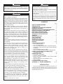
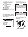
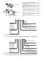
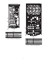
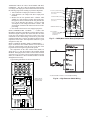
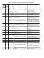
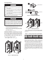
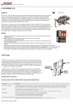
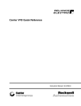
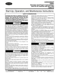
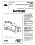
19XRV, 23XRV
with PIC III Controls
Rockwell PowerFlex 755 VFD Option
Start-Up and Service Instructions
SAFETY CONSIDERATIONS
Centrifugal and screw compressor liquid chillers are
designed to provide safe and reliable service when operated within design specifications. When operating this
equipment, use good judgment and safety precautions
to avoid damage to equipment and property or injury to
personnel.
Be sure you understand and follow the procedures
and safety precautions contained in the chiller instructions as well as those listed in this guide.
DANGER
Failure to follow these procedures will result in severe personal injury or death.
ONLY QUALIFIED electrical personnel familiar with the
construction and operation of this equipment and the hazards involved should install, adjust, operate, or service this
equipment.
READ AND UNDERSTAND this manual and other applicable manuals in their entirety before proceeding. Failure
to observe this precaution could result in severe bodily
injury or loss of life.
DO NOT install modification kits with power applied to
the drive. Disconnect and lock out incoming power before
attempting such installation or removal. Failure to observe
this precaution could result in severe bodily injury or loss
of life.
UNUSED WIRES in conduit must be grounded at both
ends to avoid a possible shock hazard caused by induced
voltages. Also, if a drive sharing a conduit is being serviced
or installed; all drives using this conduit should be disabled
to eliminate the possible shock hazard from cross-coupled
motor leads. Failure to observe these precautions could
result in bodily injury.
DO NOT VENT refrigerant relief valves within a building.
Outlet from rupture disc or relief valve must be vented outdoors in accordance with the latest edition of ANSI/
ASHRAE 15 (American National Standards Institute/
American Society of Heating, Refrigerating, and Air-Conditioning Engineers). The accumulation of refrigerant in an
enclosed space can displace oxygen and cause asphyxiation.
PROVIDE adequate ventilation in accordance with ANSI/
ASHRAE 15, especially for enclosed and low overhead
spaces. Inhalation of high concentrations of vapor is harmful and may cause heart irregularities, unconsciousness, or
death. Misuse can be fatal. Vapor is heavier than air and
reduces the amount of oxygen available for breathing.
Product causes eye and skin irritation. Decomposition
products are hazardous.
DO NOT USE OXYGEN to purge lines or to pressurize a
chiller for any purpose. Oxygen gas reacts violently with
oil, grease, and other common substances.
(Dangers continued in next column.)
DANGER
NEVER EXCEED specified test pressures, VERIFY the
allowable test pressure by checking the instruction literature and the design pressures on the equipment nameplate.
DO NOT USE air for leak testing. Use only refrigerant or
dry nitrogen.
DO NOT VALVE OFF any safety device.
BE SURE that all pressure relief devices are properly
installed and functioning before operating any chiller.
THERE IS A RISK OF INJURY OR DEATH by electrocution. High voltage may be present on the motor leads
even though the motor is not running. Open the power supply disconnect before touching motor leads or terminals.
WARNING
Failure to follow these procedures may result in personal
injury or death.
DO NOT USE TORCH to remove any component. System
contains oil and refrigerant under pressure.
To remove a component, wear protective gloves and goggles and proceed as follows:
a. Shut off electrical power to unit.
b. Recover refrigerant to relieve all pressure from system using both high-pressure and low pressure ports.
c. Traces of vapor should be displaced with nitrogen
and the work area should be well ventilated. Refrigerant in contact with an open flame produces toxic
gases.
d. Cut component connection tubing with tubing cutter
and remove component from unit. Use a pan to catch
any oil that may come out of the lines and as a gage
for how much oil to add to the system.
e. Carefully unsweat remaining tubing stubs when necessary. Oil can ignite when exposed to torch flame.
DO NOT work on high-voltage equipment unless you are a
qualified electrician.
DO NOT WORK ON electrical components, including
control panels, switches, VFD, or oil heater until you are
sure ALL POWER IS OFF and no residual voltage can
leak from capacitors or solid-state components.
LOCK OPEN AND TAG electrical circuits during servicing. IF WORK IS INTERRUPTED, confirm that all circuits are de-energized before resuming work.
AVOID SPILLING liquid refrigerant on skin or getting it
into the eyes. USE SAFETY GOGGLES. Wash any spills
from the skin with soap and water. If liquid refrigerant
enters the eyes, IMMEDIATELY FLUSH EYES with
water and consult a physician.
(Warnings continued on next page.)
Manufacturer reserves the right to discontinue, or change at any time, specifications or designs without notice and without incurring obligations.
Catalog No. 04-53190033-01
Printed in U.S.A.
Form 19/23-6SS
Pg 1
8-15
Replaces: 19/23-4SS
WARNING
CAUTION
DO NOT ATTEMPT TO REMOVE fittings, covers, etc.,
while chiller is under pressure or while chiller is running.
Be sure pressure is at 0 psig (0 kPa) before breaking any
refrigerant connection.
USE only repair or replacement parts that meet the code
requirements of the original equipment.
PERIODICALLY INSPECT all valves, fittings, and piping
for corrosion, rust, leaks, or damage.
DO NOT re-use compressor oil or any oil that has been
exposed to the atmosphere. Dispose of oil per local codes
and regulations.
DO NOT leave refrigerant system open to air any longer
than the actual time required to service the equipment. Seal
circuits being serviced and charge with dry nitrogen to prevent oil contamination when timely repairs cannot be completed.
CAUTION
Failure to follow these procedures may result in personal
injury or damage to equipment.
TO AVOID an electric shock hazard, verify that the voltage
on the bus capacitors has discharged completely before servicing. Check the DC bus voltage at the power terminal
block by measuring between the +DC and -DC terminals,
between the +DC terminal and the chassis, and between the
-DC terminal and the chassis. The voltage must be zero for
all three measurements.
THE USER is responsible to conform with all applicable
local, national, and international codes. Failure to observe
this precaution could result in damage to, or destruction of,
the equipment.
THIS DRIVE contains ESD (electrostatic discharge) sensitive parts and assemblies. Static control precautions are
required when installing, testing, servicing or repairing this
assembly. Component damage may result if ESD control
procedures are not followed. For static control procedures,
reference Rockwell publication Guarding Against Electrostatic Damage, or any other applicable ESD protection
handbook.
DO NOT alter the setting of any jumper. Failure to observe
this precaution could result in damage to, or destruction of,
the equipment.
USE OF power correction capacitors on the output of the
drive can result in erratic operation of the motor, nuisance
tripping, and/or permanent damage to the drive. Remove
power correction capacitors before proceeding. Failure to
observe this precaution could result in damage to, or
destruction of, the equipment.
MOST CODES require that upstream branch circuit protection be provided to protect input power wiring. If fuses
are chosen as the protection method, refer to the PowerFlex
750 user manual. Failure to observe this precaution could
result in damage to, or destruction of, the equipment.
DO NOT route signal and control wiring with power wiring in the same conduit. This can cause interference with
drive operation. Failure to observe this precaution could
result in damage to, or destruction of, the equipment.
DISTRIBUTION SYSTEM short circuit capacity shall not
exceed the rating of the drive. Failure to observe this precaution could result in damage to, or destruction of, the
equipment.
DO NOT STEP on refrigerant lines. Broken lines can whip
about and release refrigerant, causing personal injury.
DO NOT climb over a chiller. Use platform, catwalk, or
staging. Follow safe practices when using ladders.
USE MECHANICAL EQUIPMENT (crane, hoist, etc.) to
lift or move inspection covers or other heavy components.
Even if components are light, use mechanical equipment
when there is a risk of slipping or losing your balance.
BE AWARE that certain automatic start arrangements
CAN ENGAGE THE VFD, TOWER FAN, OR PUMPS.
Open the disconnect ahead of the VFD, tower fans, or
pumps.
(Cautions continued in next column.)
CONTENTS
Page
SAFETY CONSIDERATIONS . . . . . . . . . . . . . . . . . . . . 1,2
INTRODUCTION . . . . . . . . . . . . . . . . . . . . . . . . . . . . . . . . . . 2
ABBREVIATIONS AND EXPLANATIONS . . . . . . . . . . 3
Required Publications . . . . . . . . . . . . . . . . . . . . . . . . . . . . 3
Getting Assistance from Rockwell Automation . . . 3
IDENTIFYING DRIVE COMPONENTS . . . . . . . . . . . 3-6
Opening the VFD Access Door . . . . . . . . . . . . . . . . . . . 3
Drive Assembly Catalog Number . . . . . . . . . . . . . . . . . 4
Components and Physical Data . . . . . . . . . . . . . . . . . . 4
START-UP . . . . . . . . . . . . . . . . . . . . . . . . . . . . . . . . . . . . . . 7-9
Alternate Wire Lugs . . . . . . . . . . . . . . . . . . . . . . . . . . . . . . 7
Verify Installation. . . . . . . . . . . . . . . . . . . . . . . . . . . . . . . . . 7
Configure the VFD. . . . . . . . . . . . . . . . . . . . . . . . . . . . . . . . 8
Commissioning the Unit. . . . . . . . . . . . . . . . . . . . . . . . . . 8
Check Internal Jumpers . . . . . . . . . . . . . . . . . . . . . . . . . . 8
SERVICE . . . . . . . . . . . . . . . . . . . . . . . . . . . . . . . . . . . . . 10-20
Troubleshooting the Drive . . . . . . . . . . . . . . . . . . . . . . . 10
• ICVC ALERT CODES
• ICVC ALARM CODES
• TEST EQUIPMENT NEEDED TO TROUBLESHOOT
• VERIFYING THAT DC BUS CAPACITORS ARE DISCHARGED
• HIGH TEMPERATURE ALARMS
• MAIN CONTROL BOARD (MCB) COMPONENTS
Checking Power Modules and Motor Input
with Input Power Off . . . . . . . . . . . . . . . . . . . . . . . . . . 14
Servicing the Drive . . . . . . . . . . . . . . . . . . . . . . . . . . . . . . 15
• REMOVING THE DRIVE
• RIGGING THE ENCLOSURE
• REPLACING THE GATEWAY (A-B20-750-20COMM
OPTION CARD)
• CHILL PLATE FAN AND INTERNAL FAN
REPLACEMENT
Part Identification and Location . . . . . . . . . . . . . . . . . 18
APPENDIX A — WIRING SCHEMATICS . . . . . . . 21-27
INTRODUCTION
The Carrier VFD option Start-Up and Service Manual is intended for trained and qualified service personnel, and is to be
used during start-up, operation, and maintenance of Rockwell/
Allen-Bradley PF755L drive.
2
ABBREVIATIONS AND EXPLANATIONS
IDENTIFYING DRIVE COMPONENTS
Frequently used abbreviations in this manual include:
CCM
DC
DPI
ENET
ICVC
IGBT
I/O
IP
MCB
MOV
PE
PIC
PWM
SIO
STS
VFD
—
—
—
—
—
—
—
—
—
—
—
—
—
—
—
—
Chiller control schematics and VFD schematics are included in Appendix A.
Chiller Control Module
Direct Current
Drive Peripheral Interface
Ethernet
International Chiller Visual Controller
Insulated Gate Bipolar Transistor
Inputs/Outputs
Internet Protocol
Main Control Board
Metal Oxide Varistor
Protective Earthing Conductor
Product Integrated Control
Pulse Width Modulation
Sensor Input/Output
Status
Variable Frequency Drive
WARNING
DC bus capacitors retain hazardous voltages after input
power has been disconnected. After disconnecting input
power, wait five (5) minutes for the DC bus capacitors to
discharge and then check the voltage with a voltmeter rated
for the DC bus voltage to ensure the DC bus capacitors are
discharged before touching any internal components. Failure to observe this precaution could result in severe bodily
injury or loss of life.
An isolated multimeter will be needed to measure DC bus
voltage and to make resistance checks. The drive’s DC bus
capacitors retain hazardous voltages after input power has
been disconnected.
Required Publications — The Carrier VFD option
Start-Up and Service Manual must be used with the following
manuals:
• Latest version of the PowerFlex 755 AC Drives manuals
• Latest revision of the Start-Up, Operation, and Maintenance Instructions for the 19XRV or 23XRV with PIC III
Controls
Opening the VFD Access Door
WARNING
Getting Assistance from Rockwell Automation — Contact the local Rockwell Automation sales office
Before removing the drive enclosure, open access door and
verify that the DC bus voltage has dropped to zero by
checking the terminals behind the access door. Failure to
observe this precaution could result in severe bodily injury
or loss of life.
with any questions or problems relating to the products described in this manual. For technical support on drives, call the
HVAC Hotline at 1-888-926-6786, Option 1.
Before calling, have the following information available
from the Allen-Bradley data nameplate located inside the enclosure on the right wall. See Fig. 1.
• Allen-Bradley ID or CAT. NO.
• Carrier VFD Code (Carrier Part Number)
• Allen-Bradley serial number
1. Using recommended screwdriver (6.4 mm [0.25 in.] flat
or T20 star), open access door. See Fig. 2.
2. Check to be sure that the voltage between DC+ and DCand from each DC terminal to the chassis is zero before
proceeding. See Fig. 3.
ID No.: 21P-104773-40
Input Rating: 480VAC 454A 60Hz 3PH
Output Rating: 0-460VAC 477A 0-325Hz 3PH
Max. Ambient Temperature: 40°C
Short Circuit Rating: 65kA, 480V Max.
Interrupt Capacity Rating: 100kAIC
Enclosure Type: TYPE 1
Coolant Type: Refrigerant R134a
Design Pressure: 185 PSIG
Carrier Part Number: 19XVR0445335A1F
VFD Serial Number: XXXXXXXXX
Carrier Dwg. Number: 19XV04021001
Mfd. On: 08-13-10
ORDER NO: 0001772838-00001
FAC.LOC.: 1100
Fig. 1 — Allen Bradley Data Nameplate
A19-1830
Fig. 2 — Opening Access Door
A19-1831
3
1
Drive Assembly Catalog Number — See Fig. 4
L1
L2
L3
and 5 for examples of the Rockwell Automation Drive Assembly Catalog Number.
I
LOCKOUT/TAGOUT
Components and Physical Data — The 19XRV
chillers use the Allen-Bradley PF755 Frame 6 drive for the
230-amp rated application (Carrier Part No. 19XVR0230...).
See Fig. 6.
The Allen-Bradley PF755 Frame 7 drive is used for the
335-amp and 445-amp rated application (Carrier Part No.
19XVR0335... and 19XVR0445...). See Fig. 7.
See Fig. 8 for the dimensions of Frames 6 and 7 for 19XRV
chillers.
The 23XRV chiller uses the Frame 7 drive for 335-amp and
455-amp rated applications (Carrier Part No. 23XVR0335...
and 23XVR0445...). Frame 6 is not used.
See Fig. 9 for the dimensions of Frame 7 for 23XRV
chillers.
O
2
DC BUS TEST
TERMINALS
LOCATED INSIDE
ACCESS DOOR
DC+ DC–
0V
0V
MULTIMETER
Fig. 3 — Check DC Bus Terminals
A19-1814
21P - 1
0248
- 3
5
0
Meter Option
0 – No Meters
2 – Digital Meter
21P - 19XRV Std Tier
Voltage Code
1 – 480 vac, 60 Hz
2 – 380 vac, 50 Hz
3 – 380 vac, 60 Hz
4 – 400 vac, 50 Hz
5 – 400 vac, 60 Hz
6 – 415 vac, 50 Hz
7 – 415 vac, 60 Hz
Input Device
3 – 65 KAIC Capacity Breaker
4 – 100 KAIC Capacity Breaker
Enclosure
4 – Unit Mount Type 1/IP23 Liquid Cooled
5 – Unit Mount Type 1/IP23 Liquid Cooled/Air Filter
Full Load Amp Rating
(Maximum Continuous Amps)*
0248 – 248
0361 – 361
0477 – 477
a19-2380
* For Carrier applications, maximum continuous amp ratings
are 230, 335, and 445.
Fig. 4 — Rockwell Automation Drive Assembly Catalog Number Nomenclature: 19XRV Units
21PB - 1
0248
4
- 3
0
0
0
CE (Conformité Européenne)
0 – No
1 – Yes
21PB - 23XRV Std Tier
Control Power
0 – Standard
1 – High
Voltage Code
1 – 480 vac, 60 Hz
2 – 380 vac, 50 Hz
3 – 380 vac, 60 Hz
4 – 400 vac, 50 Hz
6 – 415 vac, 50 Hz
7 – 415 vac, 60 Hz
Meter Option
0 – No Meters
2 – Digital Meter
Input Device
3 – 65 KAIC Capacity Breaker
4 – 100 KAIC Capacity Breaker
Full Load Amp Rating
(Maximum Continuous Amps)*
0248 – 248
0361 – 361
0477 – 477
Enclosure
1 – Unit Mount Type 1/IP23 Air Cooled/Filter
4 – Unit Mount Type 1/IP23 Liquid Cooled
* For Carrier applications, maximum continuous amp ratings
are 230, 335, and 445.
a19-2381
Fig. 5 — Rockwell Automation Drive Assembly Catalog Number Nomenclature: 23XRV Units
4
LEGEND
NO.
1
2
3
4
5
NAME
Power Terminals
PE Grounding Studs
DC Bus and Brake
Terminals
PE-A and PE-B
DC+ and DC-
A191832
DESCRIPTION
R/L1, S/L2, T/L3, U/T1, V/T2, W/T3
Terminating point to chassis ground
for incoming motor shield
+DC, -DC, BR1, BR2
MOV and CMC Jumper Wires
Bus Voltage Test Points
A19-1833
LEGEND
Fig. 6 — Frame 6 Drive Components
NO.
1
2
3
4
5
NAME
Power Terminals
PE Grounding Studs
DC Bus and Brake
Terminals
PE-A and PE-B
DC+ and DC-
DESCRIPTION
R/L1, S/L2, T/L3, U/T1, V/T2, W/T3
Terminating point to chassis ground
for incoming motor shield
+DC, -DC, BR1, BR2
MOV and CMC Jumper Wires
Bus Voltage Test Points
Fig. 7 — Frame 7 Drive Components
5
54.00
50.00 REF
30.00
C
L
CL
a19-2379
36.00 REF
22.00
40.00
SIDE VIEW
FRONT VIEW
NOTE: Dimensions shown in inches.
Fig. 8 — 19XRV Enclosure Dimensions — Frames 6 and 7
a19-2011
NOTE: Dimensions shown in inches.
Fig. 9 — 23XRV Enclosure Dimensions — Frame 7
6
Record the following nameplate information:
1. From the Allen-Bradley nameplate (Fig. 1) located inside
the VFD enclosure:
a. Allen-Bradley ID or CAT NO.
b. Allen-Bradley Serial Number
c. Carrier Part Number
2. From the machine nameplete (Fig. 10) located inside the
VFD enclosure:
a. Chiller Serial Number
b. Chiller Model
c. Motor rated load amps
d. Motor nameplate rpm
e. Motor nameplate kW
f. Motor nameplate voltage
g. Inverter PWM (pulse width modulation) frequency
h. Voltage
3. From the drive module label (Fig. 11) located on the drive
module:
a. Model or Cat. Number
b. Serial Number
4. From the ICVC control panel screen:
a. Carrier Part Number and Revision
b. ICVC Software Number
Rockwell PowerFlex 755 drive start-up must be registered on the Rockwell website:
START-UP
DANGER
Internal components and circuit boards of the drive are live
when the drive is connected to incoming power. Coming
into contact with this voltage is extremely dangerous and
will result in severe personal injury or death.
The motor terminals U, V, W and the DC-link/brake resistor terminals B+/R+, R- are live when the drive is connected to incoming power, even if the motor is not running.
Do not make any connections when the drive is connected
to the incoming power.
After having disconnected the drive, wait until the indicators on the keypad go out (if no keypad is attached see the
indicator through the keypad base). Wait 5 more minutes
before doing any work on drive connections. Do not even
open the cover before this time has expired.
Before connecting the drive to the incoming power, make
sure that the switchgear enclosure door is closed.
WARNING
The control I/O-terminals are isolated from the mains
potential. However, the relay outputs and other I/O terminals may have a dangerous control voltage present even
when the drive is disconnected from incoming power.
Coming into contact with this voltage could result in severe
personal injury.
http://www.automation.rockwell.com/warp/default.asp
a191846
CAUTION
If other than refrigerant cooling is used, before connecting
the drive to the incoming power, make sure that the coolant
is circulating and has no leaks.
CAUTION
When working with the Drive Explorer, never use the
Rotate function as the motor will immediately start and
severe compressor damage could result.
Alternate Wire Lugs — If the incoming power wire
size does not fit the standard lug, alternate lugs may be used.
See Table 1. Note that lugs rated for a higher current than the
circuit breaker may be used.
Table 1 — Wire Lugs
CIRCUIT
BREAKER
STANDARD
ABB LUG
STANDARD
LUG CABLE
RANGE
65 KAIC
(STANDARD)
100 KAIC
(OPTIONAL)
K6TJ
(3) 2/0 - 400
MCM
Verify Installation — Record
information:
1. Job Name
2. Job Number
3. City
4. State
5. Zip Code
ALTERNATE ALTERNATE
LUG CABLE
ABB LUG
RANGE
K6TH
the
(2) 250 - 500
MCM
following
job
Fig. 10 — Machine Nameplate
7
Commissioning the Unit — The commission proce-
dure is as follows:
1. If the chiller has been stored outdoors, allow at least 24
hours room temperature stabilization prior to commissioning. Ensure any condensation that occurs as a result
of the ambient temperature is allowed to evaporate.
2. Enter parameters in the VFD_CONF screen.
3. Install surge suppression devices if required.
4. Review the power wiring and grounding to ensure that it
has been properly connected.
5. Visually examine the inside of the drive enclosure to:
a. Look for signs of corrosion or moisture residue.
b. Remove any dirt or debris.
c. Make sure all vents are clear.
6. Apply power to the drive and take thermal measurements
of the capacitor bank and power connections. Do this
again before start-up.
7. Measure and record the incoming line voltage. Line-toline voltages should be balanced within 3% as calculated
by Rockwell’s procedure below:
Measure voltages phase-to-phase and phase-to-ground.
a191924
Fig. 11 — Drive Module Label
Configure the VFD — All configurations required by
Vmax = Maximum measured phase-to-phase voltage
(A to B, B to C, C to A)
Vmin = Minimum measured phase-to-phase voltage
Imbalance Calculation Formula
the VFD are supplied by the ICVC through the VFD Gateway.
19XRV, 23XRV Std Tier VFD can operate with PIC III ICVC
and above. Any configuration changes necessary and possible
are made on the ICVC screens. A complete set of configurations is transmitted to the VFD each time the controls are powered up.
Table 2 lists parameters displayed on the 19XRV, 23XRV
PIC ICVC screen. Parameters in italics are to be entered or
confirmed at start-up. Parameters in bold are to be changed
only after consulting with Carrier service engineering.
(VAB + VBC + VCA)
3
(Vmax – Vmin) x 100
Imbalance % =
Vavg
8. Take a final thermal measurement of the capacitor bank
and power after finalizing the installation to ensure all
connections are good.
9. If a ground fault occurs, then do the following:
a. Check for a ground in the motor or motor wiring.
b. Check for damage to wiring insulation and that
wiring is dry.
c. Verify the motor wiring is separated from ground
and there is no connection between phases.
d. Check for failed IGBTs.
10. If an overcurrent fault occurs, then do the following:
a. Check for excessive load and verify load limit settings on the ICVC.
b. Check motor and wiring insulation.
c. Check parameter settings on VFD_CONF screen
in the ICVC.
Vavg
Table 2 — VFD Configurations
PARAMETER
MOTOR NAMEPLATE VOLTAGE
COMPRESSOR 100% SPEED
LINE FREQ=60 HZ? (NO=50)
RATED LINE VOLTAGE* †
RATED LINE AMPS* †
RATED LINE KILOWATTS* †
MOTOR RATED LOAD KW*
MOTOR RATED LOAD AMPS*
MOTOR NAMEPLATE AMPS
MOTOR NAMEPLATE RPM
MOTOR NAMEPLATE KW
INVERTER PWM FREQUENCY (0 = 4 KHZ,
1 = 2 KHZ)
SKIP FREQUENCY 1 (HZ)
SKIP FREQUENCY 2 (HZ)
SKIP FREQUENCY 3 (HZ)
SKIP FREQUENCY BAND LINE (HZ)
VOLTAGE % IMBALANCE
LINE VOLT IMBALANCE TIME (SEC)†
LINE CURRENT % IMBALANCE†
LINE CURRENT IMBAL TIME (SEC)†
MOTOR CURRENT % IMBALANCE
MOTOR CURRENT IMBAL TIME
INCREASE RAMP TIME (SEC)
DECREASE RAMP TIME (SEC)
SINGLE CYCLE DROPOUT (DSABLE/ENABLE)
DEFAULT
VALUE
460
YES
460
200
100
100
200
100
3456
100
1
20.0
20.0
20.0
0.0
10
10
40
10
40
10
30
30
DSABLE
=
Check Internal Jumpers — On the Main VFD Con-
trol board there are two jumpers labeled J1 HARDWARE ENABLE and J2 SAFETY ENABLE. J1 should be removed and
J2 should be in place. See Fig. 12.
Two jumper wires connect a particular terminal to chassis
ground. The MOV and AC EMI jumper should be connected
to the PE-A terminal. The COMMON MODE CAPACITORS
to GROUND jumper should be connected to a standoff rather
than the PE-B terminal.
Use the recommended tools as follows when connecting
jumper wires in Frame 6 and in Frame 7:
• Recommended torque (screws and nuts) = 1.36 N·m
(120.0 lb·in.)
• Recommended hex socket = 7 mm
• Recommended screwdriver = T20 star type
* Parameters marked with an * are not downloadable to the VFD but are used
in other calculations and algorithms in the ICVC.
† Parameters marked with a † may not be available with PIC-IV ICVC.
NOTES:
1. Parameters in italics are to be entered or confirmed at start-up.
2. Parameters in bold are to be changed only after consultation with service engineering.
8
See Fig. 13 and Fig. 14 for the correct positions of the
jumpers.
LEGEND
NO.
1
2
NAME
HIM (Human
Interface Module)
Connector
Fan Connector
Battery
Receptacle
3
4
5
6
7
8
9
a19-1921
DESCRIPTION
DPI Port 1 (HIM Cradle) connection.
Power supply for internal cooling fan
(Frames 2 and 3).
User installed CR1220 lithium coin
cell battery provides power to the
Real Time Clock (Optional, not
supplied).
DPI Port 2
Cable connection for handheld and
remote HIM options.
Embedded Ethernet/ Rotary switches for setting lowest
IP Address Selectors octet of Ethernet address (forces
address to 192.168.1.xxx).
Embedded Ethernet/ Network cable connection.
IP Connector
Jumper J2 SAFETY Safety enable jumper. Removed
ENABLE
when safety option is installed. For
additional information, refer to the
Check Internal Jumpers section on
page 8.
Jumper J1 HARDHardware enable jumper. Removed
WARE ENABLE
when a hardware enable configuration is utilized. For additional information, refer to the Check Internal
Jumpers section on page 8.
TB1
I/O terminal block.
TB1 I/O TERMINAL DESIGNATIONS
FIXED I/O
TERMINAL
Di 0ac
Di C
Di 0dc
+24V
24VC
Di 0ac
Di C
Di 0dc
+24V
24VC
NAME
Digital Input 120V AC
DESCRIPTION
Connections for AC power supply.
Digital Input Common
Digital input common
Digital Input 24V DC
Connections for DC power supply.
+24 Volt Power
Connections for drive supplied 24V power.
24 Volt Common
IMPORTANT: Wiring to pluggable terminal block connectors
should be supported by wire ties or other means to help prevent unintentional disconnection.
Fig. 12 — PF755 Main Control Board
DISCONNECTED
CONNECTED
DISCONNECTED
CONNECTED
COMMON MODE
COMMON MODE
MOV
MOV
A19-2326
A19-2325
Fig. 14 — Jumper Wire Locations — Frame 7
Fig. 13 — Jumper Wire Locations — Frame 6
9
ICVC ALARM CODES — An alarm condition is also indicated by a message at the top of the ICVC default screen. If an
alarm occurs, the drive coasts to stop. The STS (status) light on
the drive will turn from Green to Red or Yellow (see Table 3).
The detected fault message is maintained on the display until it
is cleared by pressing the RESET softkey. See the 19XRV or
23XRV Start-Up, Operation and Maintenance Instructions for
ICVC alarm codes.
TEST EQUIPMENT NEEDED TO TROUBLESHOOT —
An isolated multimeter adequately rated for the DC bus voltage will be needed to measure DC bus voltage and to make
resistance checks. Note that dedicated troubleshooting test
points are not provided.
SERVICE
WARNING
DC bus capacitors retain hazardous voltages after input
power has been disconnected. After disconnecting input
power, wait five (5) minutes for the DC bus capacitors to
discharge and then check the voltage with a voltmeter to
ensure the DC bus capacitors are discharged before touching any internal components. Failure to observe this precaution could result in severe bodily injury or loss of life.
Troubleshooting the Drive — The drive can display
two kinds of error codes on the ICVC called Alert and Alarm
codes. These codes signal a problem detected during self tuning or drive operation. Note the following differences between
Carrier and Allen-Bradley terminology:
• A warning message on the ICVC is an ALERT.
• The same warning viewed with Rockwell Drive Explorer
is a VFD ALARM.
• A failure resulting in a shutdown is seen as an ALARM
on the ICVC and as a VFD FAULT when viewed with
Drive Explorer.
CONDITION CODES
ICVC ALERT
=
VFD ALARM
ICVC ALARM
=
VFD FAULT
See Tables 3-4 and Fig. 15.
ICVC ALERT CODES — An alert condition is indicated by
a message at the top of the ICVC default screen. In addition, an
exclamation point (!) will appear next to any affected point on
an ICVC display screen. The drive will continue to operate
during the alert condition. Investigate the cause of the alert to
ensure it does not lead to a fault condition. The alert code will
automatically be cleared from the ICVC when the condition
causing the alert no longer exists. See the 19XRV or 23XRV
Start-Up, Operation and Maintenance Instructions for ICVC
alert codes.
Allen-Bradley
7
4
1
8
5
2
9
6
3
A1
91815
Fig. 15 — Drive Status Indicator
Table 3 — Drive Status Indicator Descriptions
NAME
STS (Status)
ENET
LINK
COLOR
Green
Yellow
STATE
Flashing
Steady
Flashing
Red
Steady
Flashing
Red/Yellow
Steady
Flashing Alternately
Green/Red
None (Unlit)
Flashing Alternately
Off
Red
Flashing
Steady
Flashing Alternately
Flashing
Red/Green
Green
None (Unlit)
Green
Steady
Off
Flashing
Steady
DESCRIPTION
Drive ready but not running, and no faults are present.
Drive running, no faults are present.
Drive is not running. A type 2 (non-configurable) alarm condition exists and the
drive cannot be started.
Drive is not running, a type 1 alarm condition exists. The drive can be started.
A major fault has occurred. Drive cannot be started until fault condition is
cleared.
A non-resettable fault has occurred.
A minor fault has occurred. When running, the drive continues to run. System
is brought to a stop under system control. Fault must be cleared to continue.
Use parameter 950 [Minor Flt Config] to enable. If not enabled, acts like a
major fault.
Drive is flash updating.
Adapter and/or network is not powered, adapter is not properly connected to
the network, or adapter needs an IP address.
An Ethernet/IP connection has timed out.
Adapter failed the duplicate IP address detection test.
Adapter is performing a self-test.
Adapter is properly connected but is not communicating with any devices on
the network.
Adapter is properly connected and communicating on the network.
Adapter is not powered or is not transmitting on the network.
Adapter is properly connected and transmitting data packets on the network.
Adapter is properly connected but is not transmitting on the network.
NOTES:
1. A Type 1 alarm indicates that a condition exists. Type 1 alarms
are user configurable.
2. A Type 2 alarm indicates that a configuration error exists and
the drive cannot be started. Type 2 alarms are not configurable.
10
VERIFYING THAT DC BUS CAPACITORS ARE DISCHARGED — The drive’s DC bus capacitors retain hazardous voltages after input power has been disconnected. Perform
the following steps before touching any internal components:
1. Turn off and lock out input power. Wait five minutes.
2. Verify that there is no voltage at the drive’s input power
terminals.
3. Measure the DC bus potential with a voltmeter while
standing on a non-conductive surface and wearing insulated gloves (1000 V). Measure the DC bus potential. See
Fig. 6 for the 248-amp drive and Fig. 7 for the 361 and
477-amp drives. The voltage between DC+ and DC-, and
from each DC terminal to the chassis must be zero before
proceeding.
4. Once the drive has been serviced, reapply input power.
HIGH TEMPERATURE ALARMS — Coolant flow
through the cold plate is controlled by an orifice in the refrigerant line leaving the cold plate. The orifice looks like one of the
O-ring face seal connectors and in fact is used as one of the
connections on the coolant tubing. If the orifice is present and
condenser liquid flow is present, the liquid will flash to cooler
temperature at the orifice. This temperature difference is great
enough to be easily felt.
MAIN CONTROL BOARD (MCB) COMPONENTS —
Figure 16 shows the drive module with the cover removed. To
access the control boards, loosen the screw on the face of the
keypad mount and swing the keypad mount upward.
The components on the main control board (MCB) are
shown in Fig. 17. Note the location of the terminals labeled
MCB I/O. The high-pressure switch is wired to these terminals
as shown in Fig. 18. In the event of a high condenser pressure
alarm, the connections at these terminals should be checked
and tightened if necessary.
Typical wiring schematics are shown in Appendix A.
DPI PORT 02 (COMPUTER PORT)
DIGITAL INPUT TERMINAL BLOCKS
(SLOTS 04 & 05)
ETHERNET/IP ADDRESS SWITCHES
DIGITAL OUTPUT TERMINAL BLOCKS
(SLOTS 04 & 05)
a19-1844
EMBEDDED ETHERNET/IP PORT
MCB I/O TERMINALS
(AUX FAULT /
HIGH PRESSURE FAULT /
ENABLE INPUT)
Fig. 17 — MCB (Main Control Board) Components
a19-1925
*Located outside of starter; connected by field wiring.
SWING UP KEY PAD
MOUNT TO ACCESS
CONTROL BOARDS
Fig. 18 — High Pressure Switch Wiring
a19-1843
Fig. 16 — Drive Module with Cover Removed
11
Table 4 — Powerflex 755 Fault Code Descriptions and Corrective Actions
VFD
FAULT
CODE
ON VFD
HIST
SCREEN
NONE
0
ICVC
FAULT
STATE
FAULT TYPE
206
DESCRIPTION
Processor memory fault
CORRECTIVE ACTION
Consult VFD manual to resolve generic fault.
No Entry
2
207
Auxiliary Input
Input is open.
3
210
Power Loss
Line voltage dropout
4
215
Undervoltage
Low DC bus voltage
5
166
Overvoltage
High DC bus voltage
7
217
Motor Overload
An internal electronic overload trip has occurred.
8
219
Heat Sink Overtemp
Heat sink temperature has exceeded maximum
operating temperature.
9
219
Transistor Overtemp
The output transistors have exceeded maximum
operating temperature.
12
286
HW Overcurrent
The drive output current has exceeded hardware
current limit.
13
220
Ground Fault
A current path to earth ground greater than 25%
of drive rating has occurred.
14
206
Ground Warning
The ground current has exceeded the level set in
P467.
15
206
Load Loss
17
216
20
206
The DC bus ripple
has exceeded a
preset level.
TorqPrv Spd Band
21
225
Output PhaseLoss
24
204
Decel Inhibit
33
206
AuRsts Exhausted
36
286
SW Overcurrent
Check Compressor Discharge High Pressure
switch wiring and accuracy.
Check for high condenser water temperatures,
low water flow, fouled tubes.
Check for division plate/gasket bypass. Check
for noncondensables in refrigerant.
Temporary loss of voltage. Disable Single Cycle
Dropout in VFD_CONF sceen.
Verify phase-to-phase and phase-to-ground line
voltage. VFD Circuit Board malfunction.
Contact Carrier Service.
Verify phase to phase and phase to ground line
voltage. Monitor AC line for high transient voltage conditions.
Any phase current > 106% RLA. Can result from
significant load side current imbalance when
running at full load.
Check entering condenser water temperature
and water flow rate.
Check Motor Rated Load Amps in VFD_CONF
screen.
Check that VFD refrigerant isolation valves are
open.
Check VFD refrigerant cooling orifice and refrigerant strainer.
Check for proper VFD cooling fan operation and
air flow blockage.
Check that VFD refrigerant isolation valves are
open.
Check VFD refrigerant cooling orifice and refrigerant strainer.
Check for proper VFD cooling fan operation and
air flow blockage.
Check for high entering water temperature or low
condenser water flow. Check current settings in
VFD_CONF screen.
Check the motor, motor terminals, and external
wiring to the drive output terminals for a
grounded condition.
—
To reset the processor, cycle power to chiller,
check ICVC VFD_CONF settings and save settings when exiting VFD_CONF screen.
Check VFD parameters with Drive Explorer.
Check phase-to-phase and phase-to-ground disLine Voltage imbalance
tribution bus voltage. Increase Line Voltage %
Imbalance in VFD_CONF screen.
See VFD Fault Code 15
See VFD Fault Code 15
The current in one or more phases has been lost Check Motor Current % Imbalance in
or remains below a preset level.
VFD_CONF screen.
Verify input voltage is within drive specified
limits.
Verify system ground impedance follows proper
The drive is not following a commanded decelera- grounding techniques.
tion because it is attempting to limit bus voltage.
Disable bus regulation P186 and/or add dynamic
brake resistor and/or extend deceleration time
P537 and P538.
See VFD Fault Code 15
See VFD Fault Code 15
The drive output current has exceeded the 1 ms Check for excess load, improper DC boost setcurrent rating.
ting, DC brake volts set too high.
If this fault appears, there may be a problem with
software configuration.
12
Table 4 — Powerflex 755 Fault Code Descriptions and Corrective Actions (cont)
VFD
FAULT
CODE
ON VFD
HIST
SCREEN
38
39
ICVC
FAULT
STATE
220
40
41
42
43
FAULT TYPE
Phase U to Gnd
Phase V to Gnd
DESCRIPTION
GROUND FAULT
Check wiring between drive and motor.
Check motor for grounded phase.
Check motor terminals.
Replace drive.
GROUND FAULT
Check wiring between drive and motor.
Check motor terminals.
Replace drive.
GROUND FAULT (no LF2 equivalent)
Check wiring between drive and motor.
Check motor terminals.
Replace drive.
Phase W to Gnd
44
206
Phase UV Short
Phase VW Short
Phase WU Short
Phase UNot
45
206
Phase VNot
46
206
Phase WNot
55
NONE
61
62
206
206
Shear Pin 1
Shear Pin 2
The temperature sensor on the main control
board detected excessive heat.
See VFD Fault Code 15
See VFD Fault Code 15
64
206
Drive Overload
Drive is overloaded.
65
77
206
206
78
206
OW TrqLvlTimeout See VFD Fault Code 15
IR Volts Range
See VFD Fault Code 15
FluxAmpsRef
See VFD Fault Code 15
Rang
79
206
80
206
246
87
206
91
93
94
95
96
97
206
206
206
206
206
206
100
206
107
NONE
113
206
124
141
142
143
144
145
206
206
206
206
206
206
Inverter Overtemp
CORRECTIVE ACTION
Check that VFD refrigerant isolation valves are
open. Check VFD refrigerant strainer.
See VFD Fault Code 15
See VFD Fault Code 15
Check for high entering water temperature or low
condenser water flow. Check current settings in
VFD_CONF screen.
See VFD Fault Code 15
See VFD Fault Code 15
See VFD Fault Code 15
Check that guide vanes are closed completely.
Check for high entering water temperature or low
condenser flow.
Repeat Autotune
AutoTune Aborted See VFD Fault Code 15
See VFD Fault Code 15
IXo VoltageRange Ixo voltage calculated from motor nameplate data Re-enter motor nameplate data in VFD_CONF
is too high.
screen.
Pri VelFdbk Loss
See VFD Fault Code 15
See VFD Fault Code 15
HW Enable Check See VFD Fault Code 15
See VFD Fault Code 15
Alt VelFdbk Loss
See VFD Fault Code 15
See VFD Fault Code 15
Aux VelFdbk Loss See VFD Fault Code 15
See VFD Fault Code 15
PositionFdbkLoss See VFD Fault Code 15
See VFD Fault Code 15
Auto Tach Switch
See VFD Fault Code 15
See VFD Fault Code 15
Press ICVC reset.
Parameter ChkThe checksum read from the board does not
Check VFD_CONF parameters.
sum
match the checksum calculated.
Cycle power to the drive.
Press ICVC reset.
The main control board was moved to a different
Check VFD_CONF parameters.
Replaced MCB-PB power structure. Data set to default values.
Cycle power to the drive.
Press ICVC reset.
Tracking DataErr
Internal data error
Cycle power to the drive.
App ID Changed
Application firmware changed.
Verify application version.
Autn Enc Angle
P78 [Encdrlss AngComp] is out of range.
See VFD Fault Code 15
Autn Spd Rstrct
See VFD Fault Code 15
See VFD Fault Code 15
Autotune CurReg
See VFD Fault Code 15
See VFD Fault Code 15
Autotune Inertia
See VFD Fault Code 15
See VFD Fault Code 15
Autotune Travel
See VFD Fault Code 15
See VFD Fault Code 15
Excessive Load
Motor did not come up to speed in the allotted
time.
13
Table 4 — Powerflex 755 Fault Code Descriptions and Corrective Actions (cont)
VFD
FAULT
CODE
ON VFD
HIST
SCREEN
ICVC
FAULT
STATE
168
206
210
206
211
213
291
292
293
294
295
296
315
206
206
206
206
206
206
206
206
206
FAULT TYPE
HeatSinkUnderTmp
HW En Jumper
Out
Safety Brd Fault
Safety Jumper In
HSFan Lifwe
InFan Life
MtrBrg Life
MtrBrg Lube
MachBrg life
MachBrg Lube
Excess Psn Error
DESCRIPTION
CORRECTIVE ACTION
Heatsink temperature sensor is reporting a value
below –18.7 C (–1.66 F) or the sensor feedback
circuit is open.
Check heat sink temperature sensor. Check heat
sink temperature.
See VFD Fault Code 15
See VFD Fault Code 15
See VFD Fault Code 15
See VFD Fault Code 15
See VFD Fault Code 15
See VFD Fault Code 15
See VFD Fault Code 15
See VFD Fault Code 15
See VFD Fault Code 15
See VFD Fault Code 15
See VFD Fault Code 15
See VFD Fault Code 15
See VFD Fault Code 15
See VFD Fault Code 15
See VFD Fault Code 15
See VFD Fault Code 15
See VFD Fault Code 15
See VFD Fault Code 15
See VFD Fault Code 15
See VFD Fault Code 15
Checking Power Modules and Motor Input
with Input Power Off — Use the following procedure
Table 5 — Diode Checks
to check the drive’s power module circuitry with power off:
1. Turn off and lock out input power. Wait five minutes.
2. Verify there is no voltage at the drive’s input power terminals.
3. Using a voltmeter, check the DC bus potential as described in the section Verifying That Dc Bus Capacitors
Are Discharged on page 11 to ensure the DC bus capacitors are discharged.
4. Disconnect the motor from the drive.
5. Check all AC line and DC bus fuses.
6. Use a multimeter to check the input diodes and output
IGBTs if a fuse is open. See Table 5.
7. Check motor impedance.
8. Reconnect the motor to the drive.
9. Reapply input power.
METER LEAD
(+)
R
S
T
U
V
W
DC+
WARNING
DC bus capacitors retain hazardous voltages after input
power has been disconnected. After disconnecting input
power, wait five (5) minutes for the DC bus capacitors to
discharge and then check the voltage with a voltmeter to
ensure the DC bus capacitors are discharged before touching any internal components. Confirm that the DC bus has
discharged before performing diode checks. Failure to
observe this precaution could result in severe bodily injury
or loss of life.
DC-
(-)
DC+
DCDC+
DCDC+
DCDC+
DCDC+
DCDC+
DCR
S
T
U
V
W
R
S
T
U
V
W
METER READING
0.5 V
Infinite (OL)
0.5 V
Infinite (OL)
0.5 V
Infinite (OL)
0.5 V
infinite (OL)
0.5 V
Infinite (OL)
0.5 V
Infinite (OL)
Infinite (OL)
0.5 V
NOTE: Digital meters require a special diode check function
because the current sourced by the meter during a normal resistance (Ohms) test is too low to accurately test a diode. Make sure
the meter is set to the diode test function. Voltage readings may not
be exact as shown in above table, but look for consistency during
each of the 4 tests. When performing a test that should return infinity
(OL) as shown in above table, you may see a value slowly climbing
toward infinity. This is a result of the meter charging a capacitor and
is normal.
14
Servicing the Drive
1
L1
L2
L3
I
WARNING
LOCKOUT/TAGOUT
To guard against possible personal injury and/or equipment
damage:
1. Inspect all lifting hardware for proper attachment before lifting drive.
2. Do not allow any part of the drive or lifting mechanism to make contact with electrically charged conductors or components.
3. Do not subject the drive to high rates of acceleration
or deceleration while transporting to the mounting location or when lifting.
Do not allow personnel or their limbs directly underneath
the drive when it is being lifted and mounted.
O
A19-1814
2
DC BUS TEST
TERMINALS
LOCATED INSIDE
ACCESS DOOR
DC+ DC–
0V
0V
MULTIMETER
Fig. 20 — Check DC Bus Terminals
WARNING
DC bus capacitors retain hazardous voltages after input
power has been disconnected. After disconnecting input
power, wait five (5) minutes for the DC bus capacitors to
discharge and then check the voltage with a voltmeter to
ensure the DC bus capacitors are discharged before touching any internal components. Failure to observe this precaution could result in severe bodily injury or loss of life.
SLIDE
ENCLOSURE
FORWARD
LOOSEN
ENCLOSURE
FASTENERS
1. Using recommended screwdriver (6.4 mm [0.25 in.] flat
or T20 star), open access door. See Fig. 19.
2. Check to be sure that the voltage between DC+ and DCand from each DC terminal to the chassis is zero before
proceeding. See Fig. 20.
3. Remove the enclosure. See Fig. 21.
REMOVING THE DRIVE — The dimensions and weights
specified must be taken into consideration when removing the
drive. All lifting equipment and lifting components (hooks,
bolts, lifts, slings, chains, etc.) must be properly sized and rated
to safely lift and hold the weight of the drive while removing it.
For 19XRV chillers, see Fig. 22. For 23XRV chillers, see
Fig. 23. The drive weights are as follows:
• Drive weight for Frame 6: 85 lb.
• Drive weight for Frame 7: 160 - 249 lb.
A19-1816
90°
Fig. 21 — Removing Enclosure
When replacing the drive, reverse the procedures and tighten to the torques for Frames 6 and 7 power terminal block listed in Table 6.
Table 6 — Frames 6 and 7 Power Terminal Block
FRAME
6
7
MAXIMUM LUG
RECOMMENDED
WIDTH
TORQUE
34.6 mm (1.36 in.) 11.3 N·m (100 in.-lb)
43.5 mm (1.71 in.) 11.3 N·m (100 in.-lb)
TERMINAL
BOLT SIZE
M8 x 1.25
M8 x 1.25
RIGGING THE ENCLOSURE — Where overhead room
and/or clearance in front of the drive enclosure is insufficient to
allow the drive to be safely removed from the enclosure, the
entire enclosure may have to be removed from the chiller.
The dimensions and weights specified must be taken into
consideration when removing the enclosure. For 19XRV chillers, the total weight for Frames 6 and 7, including drive weight
and enclosure, is 720 lb. The 23XRV chiller enclosure, including all components, weighs 975 lb. All lifting equipment and
lifting components (hooks, bolts, lifts, slings, chains, etc.) must
be properly sized and rated to safely lift and hold the weight of
the enclosure and drive while removing. See Fig. 24 and
Fig. 25.
A19-1831
Fig. 19 — Open Access Door
15
DRIVE RIGGING ACCESS
DRIVE WIDTH + 4 IN.
FRONT CORNER OF
DRIVE COMPARTMENT
IS REMOVABLE
ENCLOSURE TOP
IS REMOVABLE
DRIVE POSITIONED FOR
VERTICAL LIFT
DRIVE EXTENDS BEHIND
MAIN ENCLOSURE
SUPPORT FROM
BELOW
a19-1817
A19-2012
SIDE VIEW
Fig. 23 — 23XRV Enclosure Access for Removing
Drive
FRONT VIEW
DRIVE RIGGING
ACCESS
2 IN.
2 IN.
<45°
A19-1837
>1/2 A
A
DRIVE POSITIONED FOR
VERTICAL LIFT
Fig. 24 — Rigging the Enclosure, Frame 6
<45°
DRIVE EXTENDS
BEHIND MAIN
ENCLOSURE
>1/2 A
A
A19-1838
SUPPORT FROM
BELOW
A19-1818
SIDE VIEW
Fig. 22 — 19XRV Enclosure Access
for Removing Drive
Fig. 25 — Rigging the Enclosure, Frame 7
16
REPLACING THE GATEWAY (A-B20-750-20COMM
OPTION CARD) — Follow these steps for removing and replacing the existing gateway:
1. Disconnect power to the drive. Before removing the enclosure, open the access door on the front of the drive.
See Fig. 19.
2. Check to be sure that the voltage between DC+ and DCand from each DC terminal to the chassis is zero before
proceeding. See Fig. 20.
3. Remove the enclosure. See Fig. 21.
4. Remove the 2 screws securing the mounting plate and remove the mounting plate and COMM card. See Fig. 26.
5. Mount the new COMM card and mounting plate and attach with the 2 screws removed in Step 4. See Fig. 27.
6. Use the shorter ribbon cable to connect the plug on the
COMM card to the connector on the mounting plate. See
Fig. 26.
7. Install the enclosure. See Fig. 21.
MOUNTING PLATE
GATEWAY
A19-1820
Fig. 27 — Mount COMM Card Plate to Drive
GATEWAY
CHILL PLATE FAN AND INTERNAL FAN REPLACEMENT — Follow these steps to replace the chill plate fan and
internal fan in Frames 6 and 7.
Frame 6 (chill plate fan kit Z1P-FAN-A6-A):
1. Disconnect power to the drive. Before removing the enclosure, open the access door on the front of the drive.
See Fig. 19.
2. Check to be sure that the voltage between DC+ and DCand from each DC terminal to the chassis is zero before
proceeding. See Fig. 20.
3. Remove the enclosure. See Fig. 21.
4. Remove and replace the chill plate fan. See Fig. 28.
5. Remove and replace the internal fan. See Fig. 29.
6. Install the enclosure. See Fig. 21.
MOUNTING PLATE
0.45-0.67 N-m
(4.0-6.0 lb.-in.)
3 PLACES
RIBBON CABLE
A19-1819
CHILL PLATE
FAN POWER
CONNECTION
Fig. 26 — COMM Card
CHILL PLATE FAN
A19-1839
T20
2.6 N•m (23 lb•in.)
Fig. 28 — Chill Plate Fan, Frame 6
17
4. Remove and replace the chill plate and internal fans. See
Fig. 30.
5. Install the enclosure. See Fig. 21.
5.20 N•m
(46 lb•in.)
2.6 N•m
(23 lb•in.)
T15
T20
INTERNAL FANS
T15
2.6 N•m (23 lb•in.)
INTERNAL FAN
X2
T20
A19-1840
2.6 N•m
(23 lb•in.)
Fig. 29 — Internal Fan, Frame 6
A19-1841
T20
CHILL PLATE FANS
2.6 N•m (23 lb•in.)
Frame 7 (chill plate fan kit Z1P-FAN-A7-A):
1. Disconnect power to the drive. Before removing the enclosure, open the access door on the front of the drive.
See Fig. 19.
2. Check to be sure that the voltage between DC+ and DCand from each DC terminal to the chassis is zero before
proceeding. See Fig. 20.
3. Remove the enclosure. See Fig. 21.
Fig. 30 — Chill Plate and Internal Fans, Removal
and Replacement, Frame 7
Part Identification and Location — See Fig. 31-34
for parts descriptions and locations.
CR6
1
2
CABLE
ACCESS
CUTOUT
TB1,TB2,
FU1-FU3
1
TB4
DIST.
SIDE
FU2
TB1 TB2 FU1 FU3
CB2
1
1
CB
TB4
CR1
CR2
CR3
CR4
CR5
CR6
1
3P
KTK/FNQ-R
30A
PT1
4
3
2
SECONDARY
SIDE
TOWARD
DOOR
2
2
PT1
5
SECONDARY SIDE
LEFT SIDEWALL
VIEW FROM INSIDE
FRONT VIEW
DOOR REMOVED
1
2
3
4
5
6
—
—
—
—
—
—
LEGEND
Power Module
Input Circuit Breaker
15 Amp Control Circuit Breaker
Control Transformer
Control Fuses
Control Relays (CR1 - CR6)
80
Fig. 31 — 19XRV Assembly Parts
18
876 5 876 5 876 5 876 5 876 5 876 5
4 3 2 1 4 3 2 1 4 3 2 1 4 3 2 1 4 3 2 1 4 3 2 1 1 2 3 4 5 6 7 8 9 10 11 12 13 14 15 16 17 18 19 20 21 22 23 24 25 26 27 28 29 30 31 32 33 34 35 36 37 38 39 40 41 42 43 44 45 46 47 48 49 50 51 52 53 54 55 56 57 58 59 60 61 62 63 64 65 66 67 68 69 70 71 72 73 74 75 76 77 78 79 80
LINECB1 PE
876 5 876 5 876 5 876 5 876 5 876 5
4 3 2 1 4 3 2 1 4 3 2 1 4 3 2 1 4 3 2 1 4 3 2 1 1 2 3 4 5 6 7 8 9 10 11 12 13 14 15 16 17 18 19 20 21 22 23 24 25 26 27 28 29 30 31 32 33 34 35 36 37 38 39 40 41 42 43 44 45 46 47 48 49 50 51 52 53 54 55 56 57 58 59 60 61 62 63 64 65 66 67 68 69 70 71 72 73 74 75 76 77 78 79 80
14
13 14
13 14
13 14
13 14
13 14
13
12 1110 9 12 1110 9 12 1110 9 12 1110 9 12 1110 9 12 1110 9
CR1
13 14
13 14
13 14
13 14
13 14
13
14
12 1110 9 12 1110 9 12 1110 9 12 1110 9 12 1110 9 12 1110 9
6
EA1
a19-1847
CR1
CR2
CR3
CR4
CR5
CR6
TB4
1
2
3
8
7
4
6
5
1
2
3
4
5
6
7
8
—
—
—
—
—
—
—
—
FRONT VIEW – DOORS REMOVED
RIGHT SIDEWALL
INSIDE VIEW
a23-1653
LEGEND
Input Circuit Breaker
Power Module
Control Relays (CR1 - CR6)
Control Fuses
120V Control Transformer
120V Vaporizer Heater Transformer
15 Amp Control Circuit Breaker
Cooling Fan
Fig. 32 — 23XRV Assembly Parts
19
a19-1848
NOTE: When replacing the Main Control Board (Item No. 5) the jumper
marked “J1 HARDWARE ENABLE” must be removed and the jumper
marked “J2 SAFETY ENABLE” must be left in place.
1
2
3
4
5
6
7
8
—
—
—
—
—
—
—
—
LEGEND
PF750 Series, Precharge Kit
PF750 Series, Gate Interface
PF750 Series, Power Interface
PowerFlex 750 Series, Flange Gasket
PF755 Main Control Board
PF750 Series, Backplane Interface
PF750 Series, Type 4X/12 Chill Plate (Heatsink) Fan Kit
Chill Plate Fan
Fig. 33 — Frame 6 Parts
1
2
3
4
5
6
7
8
9
10
—
—
—
—
—
—
—
—
—
—
LEGEND
Slot for Gateway (Gateway Not Shown)
PF750 Series, Backplane Interface
PF750 Series, Type 4X/12 Heatsink Fan Kit
PF750 Series, Power Interface
PF750 Series, Bus Cap Assembly
PF750 Series, Power Interface Cable
PF750 Series, Current Transducer Kit
PF750 Series, Precharge Kit
Slot for 24V I/O Module (24V I/O Module Not Shown)
PF755 Main Control Board
NOTE: When replacing the Main Control Board (Item No. 10) the
jumper marked “J1 HARDWARE ENABLE” must be removed and
the jumper marked “J2 SAFETY ENABLE” must be left in place.
a19-1849
Fig. 34 — Frame 7 Parts
20
21
**
CB
CCM
HGBP
ICVC
UPC
—
—
—
—
—
a19-2378
Denotes Component Terminal
Wire Splice
Denotes Conductor Male/Female Connector
Option Wiring
Denotes Motor Starter Panel Conn
Denotes Power Panel Terminal
Denotes Oil Pump Terminal
Denotes Control Panel Terminal
LEGEND
Circuit Breaker
Chiller Control Module
Hot Gas Bypass
International Chiller Visual Controller
Universal Protocol Controller
APPENDIX A — WIRING SCHEMATICS
19XRV CHILLER CONTROL SCHEMATIC
a23-1731
22
NOTES:
1. Liquid flow circuit: to install optional flow device, wire as shown (N.O.) and replace
jumper with a 4.3k resistor.
2. For TP compressor, the condenser flow switch must be installed in series with the cooler
flow switch. Do not connect condenser flow switch to J3 (Lower) 23 and 24.
3. For TP compressor, remove 4.3k resistor between J3 (Lower) 20 and 21.
APPENDIX A — WIRING SCHEMATICS (cont)
23XRV CHILLER CONTROL SCHEMATIC
APPENDIX A — WIRING SCHEMATICS (cont)
ROCKWELL POWERFLEX 755 WIRING SCHEMATIC (Typical)
19XRV (Typical)
SEE METER OPTION
DETAIL
a19-2327
See Legend on page 24.
23
APPENDIX A — WIRING SCHEMATICS (cont)
ROCKWELL POWERFLEX 755 WIRING SCHEMATIC (Typical) (cont)
19XRV (Typical) (cont)
a19-2331
24
CAP
CB
COM
COMM
COND
CR
DPI/SI
—
—
—
—
—
—
—
EA
EMI
EVAP
FU
GND
JMPR
M
NC
NO
PE
POD
REM
RO
ROC
SHLD
TB
—
—
—
—
—
—
—
—
—
—
—
—
—
—
—
—
LEGEND
Capacitor
Circuit Breaker
Common
Communication
Condenser
Control Relay
Internal Communication Protocols
Connections
Electrical Assembly
Electro-Magnetic Interference
Evaporator
Fuse
Ground
Jumper
Motor
Normally Closed
Normally Open
Potential Earth (Ground)
I/O Card Mounting Board Slot
Remote
Relay Output
Relay Output Common
Shield
Terminal Block
APPENDIX A — WIRING SCHEMATICS (cont)
ROCKWELL POWERFLEX 755 WIRING SCHEMATIC (Typical) (cont)
23XRV (Typical)
a19-2328
See Legend on page 26.
25
APPENDIX A — WIRING SCHEMATICS (cont)
ROCKWELL POWERFLEX 755 WIRING SCHEMATIC (Typical) (cont)
23XRV Typical (cont)
a19-2329
26
CAP
CB
COM
COMM
COND
CR
DPI/SI
—
—
—
—
—
—
—
EA
EMI
EVAP
FU
GND
JMPR
M
NC
NO
PE
POD
REM
RO
ROC
SHLD
TB
—
—
—
—
—
—
—
—
—
—
—
—
—
—
—
—
LEGEND
Capacitor
Circuit Breaker
Common
Communication
Condenser
Control Relay
Internal Communication Protocols
Connections
Electrical Assembly
Electro-Magnetic Interference
Evaporator
Fuse
Ground
Jumper
Motor
Normally Closed
Normally Open
Potential Earth (Ground)
I/O Card Mounting Board Slot
Remote
Relay Output
Relay Output Common
Shield
Terminal Block
APPENDIX A — WIRING SCHEMATICS (cont)
ROCKWELL POWERFLEX 755 WIRING SCHEMATIC (Typical) (cont)
19XRV,23XRV METER OPTION
a19-2330
27
© Carrier Corporation 2015
Manufacturer reserves the right to discontinue, or change at any time, specifications or designs without notice and without incurring obligations.
Catalog No. 04-53190033-01
Printed in U.S.A.
Form 19/23-6SS
Pg 28
8-15
Replaces: 19/23-4SS