1
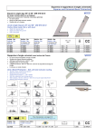
Contact Lite, Contact Lite Comfort
Contact World
description of new software functions
Please read carefully !
Introduction
This manual describes the new parts and the new functionality with the graphical display, wich
comes now together with all:
“Contact World”,
“Contact Lite” and
“Contact Lite Comfort”
units.
table of contents
1. related parts
2
2. unit startup
3
3. userlevel management
4
4. second-instrument-status (2IS)
4
5. patient chair management
5
6. timer function
5
7. instrument displays
6
8. water unit setup
7
9. instrument flush program
8
10. configuration of SoftDIP-switches
9
11. present SoftDIP-switch overview
11
document informations:
author:
date:
version:
Thomas Franz
technical office for research & development
17.06.2009
V02.00.00
Ritter® Concept GmbH
Bahnhofstraße 65, 08297 Zwönitz
Fon: 037754/13-0, Fax: 037754/13-280
e-mail: [email protected]
Internet: http://www.ritterconcept.com
Ritter® Concept GmbH
page 1
description of new software functions
Please read carefully !
Contact Lite, Contact Lite Comfort
Contact World
1. related parts
For using the new display including the new software functions, the
following parts are needed:
F1327-432
Basis
F1339-276
REV.1.0
picture 1
new tableau with greater and clear display window including
new graphical display (no image)
S+C version
H version
part.no.: 0000999258
part.no.: 0000999259
F1327-457/
-458 Tisch
F1339-277
REV.1.0
picture 2
new microcontroller for basis (see pict. 1!):
F001339276
starting with revision REV 1.0
new microcontroller for tableau (see pict. 2!):
F001339277
starting with revision REV 1.0
picture 3
new graphical display included within tableau (see pict. 3+4!):
F001337475
Language is selectable between english and german by
changing the jumper setting.
If necessary the contrast of the display can be adjusted by
using the potentiometer.
contrast
adjustment
picture 4
language setting:
new microcontroller for display (see pict. 5!):
F001339273
starting with revision Rev 1.1
(controller will be on a socket in future versions for software updates)
F1339-273
Rev.1.1
picture 5
english
german
resistor with heat sink for retrofitting inside the water
unit (see pict. 6!):
0000253549
(Please refer to external manual for installation of the resitor in existing units!)
inside water unit:
picture 6
Ritter® Concept GmbH
page 2
Contact Lite, Contact Lite Comfort
Contact World
description of new software functions
Please read carefully !
2. unit startup
display (approx. 2s):
When you switch ON the unit with the main power switch, for approx.
2 seconds a startup screen is displayed while the display is initialising.
display (approx. 5s):
After the startup screen you will be informed about the installed software revisions. These informations are displayed for approx. 5
seconds.
“Display” means controller F1339-273 on board F1327-475
“Tableau” means controller F1339-277 on board F1327-458/458
Then you will be informed for approx. 2 seconds about the actual
activated user lever (please refer to point 2.!)
display (approx. 2s):
display:
After completion of startup sequence, the display will show the
“Ritter”-Logo, wich means, that the unit is ready to use.
Ritter® Concept GmbH
page 3
Contact Lite, Contact Lite Comfort
Contact World
description of new software functions
Please read carefully !
3. userlevel management
The new software includes a total of 4 user levels. Inside each of these
levels the following settings are being stored:
- all instrument settings for turbines, motors and scaler
- 4 positions for the patient chair
(this means a total of 16 patient chair positions)
- the presetted time value for the timer function
(please refer to point 6.!)
change user level
press short:
display (approx. 2s):
- the second-instrument-status (2IS) of every instrument
(please refer to point 4.!)
In order to switch between the user levels, please press the “star”button short, while all the instruments are in its holders. Every activation
increases the actual user level by one. The indication of the new user
level stays at the display for approx. 2s.
Generally the activated user level is been shown at the right upper
corner of the display. Only in case of the first user level is activated,
nothing is been shown.
display:
The actual activated user level is been stored also during power off.
The complete user level management can be deactivated by the
Soft-DIP-switch no. 4 set 1 (please refer to point 11!).
user level 3 is activated
4. second-instrument-status (2IS)
The new software comes with a totally new function, wich is called
“second-instrument-status” (2IS). Together with this function it is possible to configure for each of the instruments of the tableau a
complete second set of instrument settings including:
using 2IS
- value of power (turbine & scaler) or speed (micromotor)
- spray or chipblower activation (according to the instruments)
- Endo or Paro mode (scaler)
press short:
- revers rotation direction (micromotor)
- instrument light activation (according to the instruments)
and to alternate between these two sets very quickly and easy with
only one single keystroke.
To use the 2IS simply press the “star”-button short, when you have
taken the desired instrument out of its holder. The activation of the 2IS
is displayed by the blinking of the instrument title. Now you can change all the needed instrument settings. Every modification is been stored inside the memory automatically. If you push the “star”-button
again, the previous settings will be activated. Also this settings can be
modified in any manner and will be stored automatically.
Now you can toggle between these two different settings simply by
using the “star”-button. The blinking or non-blinking title of the instruments shows, wich setting is currently activated.
Hint:
You can define different instrument settings in different user levels,
wich leads to a total of 8 complete settings for each instrument.
The activation of the 2IS of each instrument in each user level is been
stored automatically also during power off.
The complete 2IS function can be deactivated by the Soft-DIP-switch
no. 5 set 1 (please refer to point 11!).
Ritter® Concept GmbH
while the instrument is
taken out of its holder
display:
user level 2 is activated
“Motor 1” is blinking while 2IS is
activated
press short:
in order to return to the
previous settings
page 4
Contact Lite, Contact Lite Comfort
Contact World
description of new software functions
Please read carefully !
5. patient chair management
display (approx. 2s):
If you press any chair position button, wich position was never before
stored inside the memory, there will be a relevant message shown on
the display for about 2 seconds.
display:
If one of the safety switches for the patient chair is broken or not
connected, an error message with the number of the relevant safety
switch will be shown on the display. You can clear this message by
using any button of the keyboard or the footcontroller.
number of safety switch
display:
If one of the safety switches for the patient chair is activated, an error
message with the number of the relevant safety switch will be shown on
the display. In addition all of the buttons from the keyboard with light will
blink. You can clear this message by using any button of the keyboard
or the footcontroller.
blinking
number of safety switch
6. timer function
The new software comes with an integrated timer function for different
applications.
In order to change the preset running time of the timer, simply press the
“bell”-button long, while every instrument is in its holder.
setup timer
press long:
(while every instrument
is in its holder)
display:
Now the display will show the actual time value for the timer.
Hint:
If the user level management is activated (please refer to point 1!), you
can preset a different time value for every of the 4 user levels.
user level 2 is activ
Ritter® Concept GmbH
page 5
Contact Lite, Contact Lite Comfort
Contact World
description of new software functions
Please read carefully !
In order to change the running time of the timer, use the “plus” and
“minus”-buttons to change the stored value from 10 ... 120s in steps
of 10s.The indicated value will be automatically stored inside the
memory of the unit.
By short pressing the “bell”-button again, you leave the setting mode
for the timer.
In order to start the timer function, press the “bell”-button short, while
every instrument is in its holder. The timer will start and the display
shows the remaining seconds. Simultaneously the unit starts to tick
once per second.
10 seconds before the timer ends, there will be an acustic signal
(single tone). Another acustic signal (double tone) will sound at the
end of the timer periode.
You can also press the “bell”-button short while working with any
instrument. In this case the timer will start without any graphic display.
There are only the acoustic signals (ticking + sounds) to indicate the
start of the timer, the running, the 10 seconds left and the end of the
timer function. The timer can be stopped at anytime by pressing the
“bell”-button
use:
to change actual value
in a range of 10...120s
press short:
to leave setting mode
start timer
(while every instrument
is in its holder)
press short:
display:
The timer function can be deactivated by the Soft-DIP-switch
no. 8 set 1 (please refer to point 11!). If the timer function is deactivated, the “bell”-button of the keyboart will have the normal
door-opening function using the relay contact inside the water unit.
7. instrument displays
For each instrument now the displays shows the information about
what kind of instrument is taken and the setting of power or speed.
You can use the “plus” and “minus” buttons to change the power. In
addition, when the instrument is not activated by the foot-controller, it
is possible to press and keep pressed this buttons in order to have a
faster continuous changing. This is mainly useful if you want to
change the speed of the micromotor over a greater range.
Turbine:
press and keep pressed:
to change actual setting for the
instrument power continuously
Turbine
display:
The display for the turbine shows:
- the number of turbine (1 or 2)
- the power setting for the turbine by a bargraph of 10 bars
- the percentage of power value (10% ... 100%)
- the actual user level (exept user level 1)
user level 1 is activ (no indication!)
Micromotor
Micromotor:
display:
The display for the micromotor now shows:
- the number of micromotor (1 or 2)
- the maximum speed of the micromotor by the number of
rotations in 20 steps (1.000 rpm ... 40.000 rpm)
- the actual user level (exept user level 1)
user level 2 is activ
Ritter® Concept GmbH
page 6
Contact Lite, Contact Lite Comfort
Contact World
description of new software functions
Please read carefully !
Scaler
Scaler:
The display for the turbine now shows:
display:
- the power setting for the scaler by a bargraph of 10 bars
- the percentage of power value (10% ... 100%)
- the actual user level (exept user level 1)
user level 1 is activ (no indication!)
8. water unit setup
setup time for cup filler
The water unit setup for the time of glas filling and bowl rinsing is just
the same than described inside the normal user manual. Only the
display of course has changed (please refer to the right side of this
page!).
press long:
(while every instrument
is in its holder)
display:
Hint:
Please note also, that for both functions you can only store one time
value and it is independent from the user level managment. That´s
why also the actual user will not be displayed, while changing the
time settings.
use:
to change actual value in
a range of 1...12s
press short:
to leave configuration
mode, actual value is
saved automatically
setup time for bowl flush
press long:
(while every instrument
is in its holder)
display:
Ritter® Concept GmbH
use:
to change actual value in
a range of 10...120s
press short:
to leave configuration
mode, actual value is
saved automatically
page 7
Contact Lite, Contact Lite Comfort
Contact World
description of new software functions
Please read carefully !
9. instrument flush program
The instrument flush program was introduced in an early software
revision. The operating hasn´t changed, only of course the display is
different.
In order to use the instrument flush program, simply press the
“chipblower”-button long while every instrument is in its holder.
Now the display will show the actual stored flush time. The blinking
arrow indicates to take all the instruments, wich should be flushed,
out of its holders and to put them in a suitable position for the flushing
process.
instrument flush program
press long:
(while every instrument
is in its holder)
display:
blinking
In order to change the running time of the instrument flush program,
use the “plus” and “minus”-buttons to change the stored value from
10 ... 120s in steps of 10s. The indicated value will be automatically
stored inside the memory of the unit.
In order to start the flushing process, simply press the “chipblower”button short.
to change actual value
in a range of 10...120s
use:
press short:
display:
Now the display will show the start of the flushing process by a
blinking spray symbol and the remaining seconds of flushing time.
Always after 10 seconds of flushing time there will be a short acoustic
signal.
blinking
Ritter® Concept GmbH
page 8
Contact Lite, Contact Lite Comfort
Contact World
description of new software functions
Please read carefully !
You can stop the flushing process at any time you want by pressing
the “chipblower” button again.
press short:
After you have stopped the flushing process or the complete flushing
time is elapsed, the display shows the completion of flushing time and
a long acoustic signal sounds.
Additional a blinking arrow indicates to put back the instruments to
their holders.
display:
to stop flushing process
at any time you want
blinking
In order to finish the instrument flush program and go back to the normal using of the unit, press the “chipblower”-button short after you
have put back all the instruments to their holders.
press short:
to finish instrument flush
program after all the
instruments are back in
their holders
Hint:
There is only one time value for the flushing process, wich is used for
every of the 4 user levels.
10. configuration of SoftDIP-switches
The SoftDIP-switches were introduced in an early software revision.
Now more than 8 SoftDIP-switches are available, because there are
some “Sets” with always 8 SoftDIP-switches inside.
press and keep pressed both together:
In order to enter configuration mode for SoftDIP-switches, simply
press and keep pressed together “plus” and “minus”-button during
you switch ON the unit with the main power switch.
Ritter® Concept GmbH
while switching ON the main
switch of the unit
page 9
Contact Lite, Contact Lite Comfort
Contact World
description of new software functions
Please read carefully !
display:
After the power-on procedure is finished, the display will show the first
set of 8 SoftDIP-switches and the first switch is selected for modification.
actual selected switch
number of actual set
The “plus” and “minus”-button are used to select the wanted SoftDIPswitch.
use:
With the chair control buttons the actual selected switch can be
shifted in ON or OFF position.
use:
to select the next switch
to shift actual switch into ON
position
to shift actual switch into OFF
position
With the backrest control buttons the actual set of SoftDIP-switches
can be changed. For the time being, there are a total of 3 Sets
available, but not all switches are currently used
(please refer to point 11!).
use:
to go to the next set of
switches
to go to the previous set of
switches
display:
By pressing the “star”-button short, your current SoftDIP-switch setting
will be saved, wich is signalized by an acoustic signal, and the unit
will proceed with the normal function.
Hint:
If you are not sure about the modification you have done, you can
everytime leave the configuration mode WITHOUT any modification
simply by switching off the main power of the unit without pressing
the “star”-button before.
IMPORTANT
Every modification of SoftDIP-switches is without effect, unless
you have switched OFF and ON the unit with the main power
switch. Do NOT switch OFF the unit after you´ve pressed the
“star”-button, unless you have heard the acoustic signal for
saving the complete data, otherwise modifications may be not
stored correctly.
Ritter® Concept GmbH
press short:
*
to save the actual
SoftDIP-switch setting
AFTER you have heard the
acoustic signal for saving the
SoftDIP-switch settings completely,
switch OFF and ON main power in
order to make your modifications
take effect!
page 10
Contact Lite, Contact Lite Comfort
Contact World
description of new software functions
Please read carefully !
11. present SoftDIP-switch overview
This is an overview about the current available SoftDIP-switches and
their default settings after the installation of the new software.
This overview can/will be differ from future software revisions.
SoftDIP-switch
Set
1
2
3
Ritter® Concept GmbH
no.
description
for revision REV.1.0
default
value
1
automatic operation lamp control according to activation of chair positions ON/OFF
ON
2
automatic activation of bowl flush when chair reaches spitton position ON/OFF
OFF
3
lowspeed-mode for brushless motors is available ON/OFF
ON
4
activation of user level management function ON/OFF
ON
5
activation of second instrument status (2IS) ON/OFF
ON
6
turn-off delay (OFF) or no turn-off delay (ON) for sprayair when using spraywater
OFF
7
activation control values for new (ON) or old (OFF) types of proportional valves
ON
8
using of timer function (ON) or relay contact for door-opener (OFF)
ON
1
currently unused
OFF
2
currently unused
OFF
3
currently unused
OFF
4
currently unused
OFF
5
currently unused
OFF
6
currently unused
OFF
7
currently unused
OFF
8
currently unused
OFF
1
currently unused
OFF
2
currently unused
OFF
3
currently unused
OFF
4
currently unused
OFF
5
currently unused
OFF
6
currently unused
OFF
7
currently unused
OFF
8
currently unused
OFF
page 11