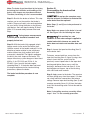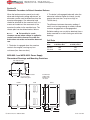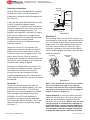
1
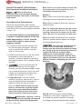
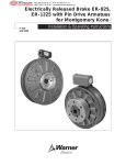
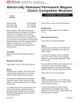
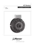
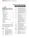
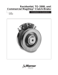
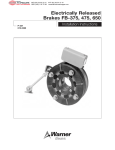
MEX (55) 53 63 23 31
DIST. AUTORIZADO QRO (442) 1 95 72 60
®
MTY (81) 83 54 10 18
[email protected]
Electrically Released Brakes
ER 825 and 1225 Heavy Duty
P-251
819-0121
Installation Instructions
An Altra Industrial Motion Company
MEX (55) 53 63 23 31
DIST. AUTORIZADO QRO (442) 1 95 72 60
®
MTY (81) 83 54 10 18
[email protected]
This service manual tells how to install, adjust, and maintain your Warner Electric brake. It also
contains information for part replacements when needed.
Warner Electric Electrically Released Brakes are high performance, high torque units. To obtain the
required performance and life, the brake must be installed exactly in accordance with the instructions
in this service manual.
The Warner Electric warranty does not apply to any unit which is not installed, used, operated and
maintained in accordance with Warner Electric's instructions.
Contents
Introduction . . . . . . . . . . . . . . . . . . . . . . . . . . . . . . . . . . . . . . . . .2
Installation Instructions . . . . . . . . . . . . . . . . . . . . . . . . . . . . . . . .3
Controls Used . . . . . . . . . . . . . . . . . . . . . . . . . . . . . . . . . . . . . . .5
Ohmmeter Procedure to Detect Armature Release . . . . . . . . . . .8
Coil Data . . . . . . . . . . . . . . . . . . . . . . . . . . . . . . . . . . . . . . . . . . .8
MCS-805-1, MCS-805-2 Mounting Dimensions . . . . . . . . . . . . .8
Operating Instructions . . . . . . . . . . . . . . . . . . . . . . . . . . . . . . . . .9
Dimensions and Specifications . . . . . . . . . . . . . . . . . . . . . . . . .11
Bushing Part Numbers . . . . . . . . . . . . . . . . . . . . . . . . . . . . . . . .12
Exploded View . . . . . . . . . . . . . . . . . . . . . . . . . . . . . . . . . . . . . .13
Parts List . . . . . . . . . . . . . . . . . . . . . . . . . . . . . . . . . . . . . . . . . .13
Warranty . . . . . . . . . . . . . . . . . . . . . . . . . . . . . . . . . . . . . . . . . .BC
ER-825 and ER-1225
Introduction
Warner Electric Electrically Released Brakes
function on the same principle of "response to
magnetic attraction" that operates other Warner
Electric brakes and clutches. Braking torque in
the Electrically Released Brake depends on
permanent magnets rather than electromagnets.
With the power off, the unit produces full
braking torque. The brake is released by
reversing the direction of flux flow in an electromagnetic coil, thus opposing the field produced
by the permanent magnets.
The opposition to and cancellation of electromagnetic force which releases the brake occurs
nominally at one value of ampere turns. This
ampere turn value can vary among brakes
because of allowable manufacturing tolerances.
2
Warner Electric • 800-825-9050
Release voltage varies mainly because of coil
tolerance and autogap spring variations.
Properly adjusting the power supply voltage is
important so the autogap springs will separate
the magnet and armature, causing full release of
the brake.
Ceramic permanent magnets, which are the
heart of Electrically Released Brakes, are not
subject to fatigue losses, therefore, Warner
Electric Electrically Released Brakes are
self-adjusting.
Warner Electric Electrically Released Brakes are
“burnished” at the factory to assure rated torque
shortly after initial application. Very little
additional wear-in is required.
P-251 • 819-0121
MEX (55) 53 63 23 31
DIST. AUTORIZADO QRO (442) 1 95 72 60
®
MTY (81) 83 54 10 18
[email protected]
Sizes ER-825 and ER-1225 with Spline
Drive Armatures Installation Instructions
Failure to follow these
instructions may result in product damage,
equipment damage, and serious or fatal injury
to personnel.
Basic Mechanical Considerations
Electrically released brakes require special
mounting considerations. Please review the items
listed below prior to starting installation contained
in steps 1-12.
A. If the brake magnet is to be mounted to
a surface of magnetic material, isolate the
brake approximately 1/2 inch from the
surface with a plate or spacer of nonmagnetic material.
B. If a choice of armature shaft material exists,
this should also be nonmagnetic. Materials
such as type 302-304 stainless have been
used very successfully.
C. In order to minimize stray flux, the unit should
be exposed as much as possible or, if
enclosed, it should be placed in a housing of
nonmagnetic material such as stainless steel or
aluminum.
D.
Note: Failure to set control voltage using the step
by step procedures in this manual may cause
overheating and premature failure.
Section 1
Step 1: Check to insure that the magnet and its
mounting surface are clean and free from burrs.
Step 2: Bolt the magnet in place with capscrews
and lockwashers.
Note: The magnet pilot diameter must be concentric to the shaft within .010 inch T.I.R. The magnet
mounting surface must be square with the shaft
within .006 inch T.I.R. measured at the bolt circle.
Step 3: Assemble the splined armature assembly
(armature, splined armature adapter and autogap
are preassembled) to the hub.
New armatures shipped from the
factory are flat to within .005 inch and this
flatness must be retained to maintain full torque.
Any attempt to pry the armature loose from the
magnet will distort the armature. When
adjusting the armature position, apply any
required force only to the hub, not to the outer
edge of the armature. Also, use care when handling the armature as dropping may also cause
distortion.
must be exercised when the
armature is moved close to the magnet
assembly since the permanent magnets create
a very strong attractive force. Injury may result
if fingers are in between the armature and
magnet when the gap is 1/2" or less.
E. Foreign Materials: If units are used on
machinery where fine, abrasive dust, chips, oil
or grit are dispelled into the atmosphere, a
protective screen over the unit may be
necessary. Where units are used near gear
boxes or transmissions requiring frequent
lubrication, means should be provided to
protect the friction surfaces from oil and
grease to prevent serious loss of torque
Applications requiring a vertical
shaft mounting must be reviewed and approved
by Warner Electric Applications Engineering.
Warner Electric • 800-825-9050
Figure 1
Step 3A: Place the armature-splined adapter
assembly on a flat surface, segments up. Press
the splined hub (retainer ring end first) through
the autogap spring and splined armature adapter.
P-251 • 819-0121
3
MEX (55) 53 63 23 31
DIST. AUTORIZADO QRO (442) 1 95 72 60
®
MTY (81) 83 54 10 18
[email protected]
Slip the armature hub assembly onto the brake
shaft until armature makes contact with shims.
Step 5: Using a hex wrench, tighten the hub bushing bolts alternately and evenly until tight. Using a
drift and small hammer, tap lightly at
several points around the circumference of the
taper lock bushing. Repeat this alternate tapping
and re-tightening until the specified torque is
reached and wrench no longer turns the screw
after tapping. Tighten bolts to the following:
Figure 2
Step 3B: Turn the assembly over and insert the
retainer ring in the groove. Take care not to bend
or distort retainer ring.
Step 3C: Turn the assembly over and slide the
armature against the retainer ring.
During steps 4 through 7, handle
the armature/hub assembly by the hub (Figure
3, item 2) only, making sure the armature
(Figure 3, item 3) is as close to the retainer
ring (Figure 3, item 4) as possible. Any movement of the armature on the splined hub will
reduce available armature travel and may
cause improper setting of the running air gap.
Unit
ER-825
ER-1225
Torque
87 in. lb.
290 in. lb.
Do not attempt to pull the
bushing flange flush with the hub end as
there should be 1/8” to 1/4” clearance
when tightened.
The airgap between armature and magnet must be
.062 to .125 inch. If the airgap is outside of that
range, reposition the armature hub assembly by
repeating steps 1 and 2 of the disassembly procedure and steps 4 and 5 of the assembly procedure.
.062"
Thick
Steel Shims
1
3
1/16 inch thick steel shims are
recommended for shim stock selection. Do
not use shims thicker than 1/8 inch or you will
shorten brake life by reducing available
armature travel.
Shim stock must be clean and
free of any contamination (oil, grease). Keep
fingers clear of the area between the magnet
and the armature as the armature will be
pulled sharply toward the magnet after the
gap is closed to approximately 1/2 inch.
Bushing Type
Browning Series H
Browning Series Q
5
4
1
2
3
4
–
–
–
–
Magnet
Splined Hub
Armature
Spiral
Retainer Ring
5 – Bushing
2
Friction
Material
Step 4: Place three steel shims 120 degrees
apart on the magnet as shown in Figure 3. Insert
the taper-lock bushing (Figure 3, item 5) into the
hub (Figure 3, item 2).
Figure 3
4
Warner Electric • 800-825-9050
P-251 • 819-0121
MEX (55) 53 63 23 31
DIST. AUTORIZADO QRO (442) 1 95 72 60
®
MTY (81) 83 54 10 18
[email protected]
Step 6: Electrical Connections. Several different
types of controls can be used on the ER-825.
However, only one control can be used on the
ER-1225 electrically released brakes. If you are
installing an ER-825 brake, follow the
procedures in Section I below. When completed
with Section I, proceed to Step 7. If you are
installing an ER-1225, follow the procedures in
Section II below. When completed with Section
II, proceed to Step 7.
Section I For ER-825 Brakes
ER-825 brakes require a variable voltage or
variable current control to release the brake by
offsetting the magnetic force generated by
permanent magnets. Warner Electric controls,
such as the CBC-200 (single channel) or
CBC-300 (dual channel), offer variable output
and are suitable for use with ER-825 brakes.
Connection should be made in accordance with
instructions provided with the chosen control.
Section II For ER-1225 Brakes
Connect the MCS-805-1 or MCS-805-2 Power
Supply per the following diagram and
instructions:
3
4
5
(-)
Brake
6
(+)
7
B. A chassis ground should be provided as a
non-current conducting ground wire (color
coded green).
C. Switching. Follow instructions per control
models listed.
MCS-805-1 Standard Control Operation
1. For switching DC side: Switch connected
to terminals 7 and 8. Switch open will
allow brake to be engaged. Switch closed
will enable the release of the brake.
2. For switching AC side: Line power off will
allow brake to be engaged. Line power on
will release brake. A jumper connection
must be made between 7 and 8.
MCS-805-2 Two Step Control Operation
MCS 805-2
3
230 VAC supply to terminals 1 and 4.
Jumper to connect terminal 2 with terminal 3.
Recommended fuse is 3/4A slow blow.
8
Brake
Release
115 VAC
2
or:
3. Slower brake actuation will result when
switching the AC side.
MCS 805-1
2
A. 115 VAC supply to terminals 1 and 4.
Jumpers to connect terminal 1 with terminal
2 and terminal 3 with terminal 4.
Recommended fuse is 3/4A slow blow.
4
5
6
7
8
(+)
(-)
230 VAC
Brake
Coil
Brake
Release
ER brakes are polarity sensitive.
Connect the “+” terminal of the brake to the
“+” terminal of the control and the “-”
terminal of the brake to the “-” terminal of
the control. Plus to plus and minus to minus
connections are imperative.
Put machine in safe condition
so that when voltage is applied to the control
and switch closures are made the brake
does not rotate and machine does not run.
Warner Electric • 800-825-9050
1. With switch connected to terminals 7 and
8 and switch is open with AC power
applied, brake will be partially engaged.
2. With switch connected to terminals 7 and
8 and switch is closed with AC power
applied, brake will be fully released.
3. With switch connected to terminals 7 and
8 and switch closed with AC power
removed, brake will be fully engaged.
D. ER brakes are polarity sensitive. Connect the
plus terminal of the brake to terminal 6 on the
control and the minus terminal of the brake to
terminal 5 on the control.
P-251 • 819-0121
5
MEX (55) 53 63 23 31
DIST. AUTORIZADO QRO (442) 1 95 72 60
®
MTY (81) 83 54 10 18
[email protected]
Step 7: Apply power to the brake and remove
shims. Note: It may be required at this point to
adjust voltage to brake, to release the armature
and remove shims. Set the airgap by pressing the
armature into contact with the magnet and then
releasing. (See Figure 3) The armature should
spring back approximately 1/32-3/64 (.031-.045)
inch. If the airgap is outside of that range,
reposition the armature hub assembly by
procedure Section III and steps 4 and 5 of the
assembly procedure Section I.
Note: If armature does not engage it may be
necessary to manually engage the armature
by pressing on the back side of the armature
keeping fingers from between armature and
magnet.
9D. After armature is engaged, slowly
decrease (counter clockwise) the voltage
adjust to the brake until the brake
armature releases. Record this voltage.
9E.
Note: If armature does not spring back proceed
to voltage adjust procedure.
Step 8: Brake Release Voltage Adjustment. When
setting the brake power supply, the objective is to
achieve armature release by adjusting the coil
voltage so it counteracts the permanent magnet
to the maximum extent possible.
Two different release procedures are used,
depending on whether an ER-825 or ER-1225 is
involved. For ER-825 brakes, follow the
procedures outlined in Step 9 below. For ER-1225
brakes, follow the procedures outlined in Step 10.
Step 9: For ER-825 Brakes
Note: If the autogap is not used, an external
release force of approximately 5-10 pounds
should be applied by hand, to detect the
point of armature release.
Note: If the above voltage adjustment
procedure can not be observed visually the
alternate ohmmeter procedure should be
used. Section IV.
Step 10: For the ER-1225, the procedure is
the same as Step 9 with the exception of the
control used.
Put machine in a safe condition
so that when voltage is applied to control and
switch closures are made the brake does not
rotate and machine does not run.
The only two controls to be used are the MCS
805-1 or MCS 805-2, the voltage adjust is
performed by adjustment screw only, located
on inside of control.
9A.
10A. Follow Step 9 for adjustment of brake
control for ER-1225.
9B.
Attach multimeter to brake to monitor DC
voltage observing proper procedure for
hookup of multimeter per manufacturing
instruction.
Apply power to control and close switch
connections that allow DC voltage from
control to be applied to brake.
9C. Depending on variable control used and
output channel that brake is hooked up to,
turn voltage adjust knob or screw, counter
clockwise to 0VDC, at this point slowly
increase voltage control clockwise until
brake armature disengages. (Releases)
Record this voltage, continue to increase
voltage until brake armature engages.
6
The final voltage setting for the brake
should be the mid point between the
voltages recorded in Step 9C and 9D.
Warner Electric • 800-825-9050
10B. (For MCS-805-2 only): Set partial
engagement torque using adjusting pot
at top of control. Switch connected to
terminals 7 and 8 must be open to make
this adjustment. A setting of 10 gives
maximum torque.
After completion of installation procedure
and brake control adjustment it may be
necessary to burnish (wear in) the brake in
the application.
P-251 • 819-0121
MEX (55) 53 63 23 31
DIST. AUTORIZADO QRO (442) 1 95 72 60
®
MTY (81) 83 54 10 18
[email protected]
Note: The brake is pre-burnished at the factory
but during the installation and handling of the
brake, static torque may have been affected.
Therefore, burnishing on site is recommended.
Step 11: Burnish the brake as follows: This step
requires you to run the machine that brake is
used in. Observe all safety rules and regulations
for your facility. Using the brake as the primary
stop device, start and stop the brake 30 times.
Allow 5-10 seconds delay between Start and
Stop.
During torque measurements
machine power should be turned off and
properly locked out.
Step 12: With the brake fully engaged, attach
torque wrench to the end of the brake shaft.
Hold the wrench at the handle, and pull it in the
direction of motor rotation in one continuous
motion (without any jerky motion) until shaft
movement is detected. The highest reading on
the dial is the static torque of the brake. This
torque without any system drag must be at least
400 lb. ft. for ER-1225 and 125 lb. ft. for
ER-825. If less, burnish the brake again,
repeating Step 11. If the brake does not meet
the torque requirement after two burnishing
procedures, replace the brake.
The brake installation procedure is now
complete.
Section III
Disassembling the Armature/Hub
Assembly (Figure 3)
Do not pry the armature away
from the magnet. If armature is distorted the
entire brake must be replaced.
Note: Steps (1) and (2) are to be performed at
the brake.
Note: Make sure power to the brake is turned
off. See Figure 3 for the following two steps.
Put machine in a safe
condition so that when voltage is applied to
control and switch closures are made the
brake does not rotate and machine does not
run.
Step 1: Loosen the taper-lock bushing (item 5)
on the brake shaft.
To loosen, remove both hex screws from the
taper lock bushing (item 5, figure 3) using a hex
wrench. Insert the hex screws into the
previously vacant taped holes in the taper lock
bushing and tighten these screws until the
bushing is loosened in the hub (item 2). If the
bushing does not loosen, tap on the bushing
with a drift and small hammer.
Step 2: Apply power to the brake. The armature
will then spring away from the magnet. If it does
not, check electrical connections and release
voltage. Remove taper lock bushing (item 5) and
armature assembly (items 2 & 3) from the brake
shaft. Set the bushing aside. Do not discard the
bushing.
Note: If reinstalling armature assembly, follow
steps 1 thru 7 in the assembly procedure.
Warner Electric • 800-825-9050
P-251 • 819-0121
7
MEX (55) 53 63 23 31
DIST. AUTORIZADO QRO (442) 1 95 72 60
®
MTY (81) 83 54 10 18
[email protected]
Section IV
Ohmmeter Procedure to Detect Armature Release
When the brake armature cannot be visually
observed during brake voltage adjustment, an
ohmmeter can be used to determine when the
armature disengages. One ohmmeter lead
should be attached to the armature itself, in a
manor not to obstruct the movement of the
armature the other to the machine base. The
release point can be determined as follows:
2. The brake is disengaged (released) when the
ohmmeter indicates higher resistance (usually
greater than one ohm—may be as high as
10,000 ohms).
The difference between ohmmeter readings 1
and 2 must be large enough to reliably indicate
armature engagement or disengagement.
Reliable readings can usually be obtained from a
brake mounted on a shaft running on antifriction
bearings.
Put machine in a safe
condition so that when voltage is applied to
control and switch closures are made the
brake does not rotate and machine does not
run.
Coil Data
Unit
Size
1. The brake is engaged when the armature
contacts the magnet, causing very low
resistance (less than one ohm).
Current Draw (amp)
at 60 Volts D.C.
Resistance (ohms)
at 20°C (±10%)
ER-825
.308
195
ER-1225
.256
235
MCS-805-1 and MCS-805-2 Power Supply
Dimensional Drawings and Mounting Provisions
TOP AND BOTTOM
3.44
1.125
0.875 Diameter Knockouts
for 0.50 Conduit
Both Ends Typical
2.625
FRONT
0.28 Diameter
(4) Mtg Holes
Clearance for
.25" Screw
SIDE
7.125
BACK
6.0
0.56
5.0
8
Warner Electric • 800-825-9050
3.44
0.53
3.75
4.81
5.0
P-251 • 819-0121
MEX (55) 53 63 23 31
DIST. AUTORIZADO QRO (442) 1 95 72 60
®
MTY (81) 83 54 10 18
[email protected]
Operating Instructions
When an Electrically Released Brake is properly
installed, no further servicing, lubrication, or
maintenance should be required throughout the
life of the unit.
A worn out Electrically Released Brake can lose
its ability to produce adequate torque.
Consequently, it is imperative that the brake be
inspected frequently for wear and to insure that
it engages and disengages properly. The
frequency of inspections is dictated by usage; a
brake used in a high cycle rate and/or heavy
load application must be inspected more often
than one used less severely. Sound
maintenance practices will determine proper
inspection intervals.
Torque loss can result if the armature and
magnet wear extensively enough to cause the
detent to move off the end of the hub spline,
resulting in a loss of the autogap function. The
end of normal service will occur when the
armature wears through the friction material and
into the coil, causing an open circuit and failure
to release when voltage is applied.
Brake wear is determined by two checks. The
first determines whether the brake is about to
lose torque; the second assures that the
armature has not worn through the friction
material, endangering the coil. If either of these
checks indicates excessive wear, the unit should
be replaced.
Check No. 1
Check to insure that the distance from the
retaining ring to the splined adapter is less than
5/16 inch (see Check No. 1). This 5/16 inch
dimension can also be exceeded if the splined
hub is improperly positioned on the hub at
installation. If the 5/16 inch dimension is
exceeded, the armature must be readjusted.
Disassemble per Section III Steps 1 and 2, and
relocate brake armature as indicated starting
with step 1-7.
Warner Electric • 800-825-9050
Wear Step
Indicator
Magnet
Armature
0.31
(7.9)
Snap Ring
Adapter
Taper Lock
Bushing
Splined Hub
Check No. 1
Check No. 2
The remaining wear life of the friction surfaces can
be estimated by checking the step machined on the
O.D. of the brake magnet where the armature and
magnet meet. This step is approximately equal to
the friction material thickness. When this step is
completely covered by the armature (worn down)
with the brake engaged, the brake is worn out and
should be replaced.
New (Step)
Magnet Worn
to Step
New
Worn Out
Check No. 2
Note: A new splined hub should also be installed
when the armature and magnet are replaced.
Reusing the old splined hub or armature adapter
may prevent the armature from fully engaging the
magnet, resulting in torque loss.
Foreign Materials: If units are used on machinery
where fine, abrasive dust, chips, oil or grit are dispelled into the atmosphere, a protective screen
around the unit is necessary. Where units are used
near gear boxes or transmissions requiring frequent lubrication, means should be provided to
protect the friction surfaces from oil and grease
contamination (contact) to prevent serious loss
of torque by reducing the coefficient of friction
P-251 • 819-0121
9
MEX (55) 53 63 23 31
DIST. AUTORIZADO QRO (442) 1 95 72 60
®
MTY (81) 83 54 10 18
[email protected]
and swelling the friction material. Small amounts
of oil and grease accidentally reaching the friction
surfaces may be removed by wiping with a rag
dampened with a non petroleum, non residue
cleaning solution. In performing this operation, do
not drench the friction material. If the friction
material has been saturated with oil or grease, no
amount of cleaning will be completely effective.
Once such a unit has been placed back in service,
heat will cause the oil to be boiled to the surface
resulting in further torque loss. This unit should
then be replaced!
Fails to Release: If an Electrically Released Brake
does not release, the initial check should be to
verify the electrical connections (polarity) between
the brake coil and power supply. If the lead wires
are connected properly power supply positive “+”
terminal and brake coil “+” terminal, and power
supply negative “-” terminal and brake coil “-”
terminal, the next check is to see that the brake
release voltage adjustment is properly set in
accordance with installation instructions (See Table
of Contents).
If readjustment of the control output does not
release the brake and an AC input to the control is
present, a further check should be made to
determine if the control is faulty as follows:
Put machine in a safe condition
so that when voltage is applied to control and
switch closures are made the brake does not
rotate and machine does not run.
Connect a DC voltmeter across the brake magnet
terminals. (Do not disconnect the leads to the
terminals.) Turn the torque adjustment on the
control fully counterclockwise, then slowly turn the
adjustment screw clockwise—the voltmeter should
indicate a voltage range from approximately 30 to
75 volts for the MCS-805 series and 0 to 90 volts
using other variable supplies.
Wear Pattern
NEW
BURNISHED
To determine if there is current flow through the
magnet coil, further checks may be made as
follows: a low-range (.1 to 1 amp) amp meter
should be connected in series with one wire to
the magnet. The Coil Data chart (pages 8) lists
the correct ratings for the various sizes. These
readings are with the power on and the brake
release adjustment turned clockwise, until a
voltmeter attached to the brake magnet
terminals reads 60 VDC. If no amperes are read,
an Ohm reading of the magnet coil should be
taken. Ohmmeter checks should be made with
the power off and circuit open (To be certain,
disconnect one lead wire to the coil). Refer to
the Coil Data chart (page 8) for the
specifications of the appropriate unit. A very
high or infinite resistance reading would indicate
an open coil.
Wear Pattern: (Figure 4) As the brake is used
wear grooves will appear on the friction
surfaces. This is a normal condition, and does
not impair functioning of the unit. Never
machine the friction surfaces to remove
grooves or score marks resulting from
normal wear.
There are two main wear parts, magnet and
armature. When either is worn out, the
complete brake must be replaced.
Heat: Excessive heat and high-operating
temperatures are causes of rapid wear. Air
should be allowed to circulate around the unit
as efficiently as possible, especially if the
application requires fast, repetitive cycle
operation.
If the above checks indicate that the proper
voltage and current is being supplied to the coil,
mechanical parts should be checked to assure
that they are in good operating condition and
properly installed. (See operating instruction
under Check No. 1.)
WORN
Figure 4
10
Warner Electric • 800-825-9050
P-251 • 819-0121
MEX (55) 53 63 23 31
DIST. AUTORIZADO QRO (442) 1 95 72 60
®
MTY (81) 83 54 10 18
[email protected]
Dimensions and Specifications
ER-825 Heavy Duty Drawing I-25578
ER-1225 Heavy Duty Drawing I-25620
ER-825 & ER-1225 Magnet View
K
J
Removable
plug in ends
for .5" conduit
I
A
Q
R
Pilot
Dia. V
G
H
B
D
E
C
L
N
P
Mounting holes
are within 0.005
of true position
relative to pilot
diameter
S dia. (T) holes
equally spaced
on U dia.
O
B
Dia.
C
D
E
G
ER Size
A
Max.
825 H.D.
8.656
2.5
.156
1.250
1.765
5.625
1225 H.D.
12.671
4.093
.234
2.5
2.171
7.671
H
Max.
I
J
K
Min.
L
Min.
N
ER Size
825 H.D.
.531
5/16-18 UNC-3A
1.687
1.546
.062
.531
1225 H.D.
.546
5/16-18 UNC-3A
1.718
1.546
.062
.562
O
ER-825 H.D.
2.078
P
Max.
3.546
ER-1225 H.D.
2.50
5.031
Warner Electric • 800-825-9050
Q
3.750
R
Max.
6.75
3.750
8.79
S
T
U
V
.358
.338
.358
.338
6
4.250
6
7.250
3.503
3.501
6.378
6.376
P-251 • 819-0121
11
MEX (55) 53 63 23 31
DIST. AUTORIZADO QRO (442) 1 95 72 60
®
MTY (81) 83 54 10 18
[email protected]
Technical Ratings
Bushing Part Numbers
Static
Torque
Max.
RPM
D.C.
Voltage
Total
Weight
ER-825
125 lb. ft.
3600
90
15.6 lbs.
ER-1225
400 lb. ft.
3000
35 to 75
60.3 lbs.
Size
ER-825, 1225
ER-825
Voltage–DC
90
Resistance @ 20°C–Ohms
304
Current–Amperes
.29
Watts
26
Coil Built-up–milliseconds
400
Coil Decay–milliseconds
20
ER-1225
35-75
235
.383
35
700
20
Bore Size
ER-825
H.D. Drive
Spline Drive
ER-1225
H.D. Drive
Spline Drive
Bore Dia.
Keyway
Bore Dia.
.500-.562
1/8 x 1/16
.750-.875
Keyway
3/16 x 3/32
.375-.625
3/16 x 3/32
.937-1.250
1/4 x 1/8
.937-1.187
1/4 x 1/8
1.312-1.375
5/16 x 5/32
1.250*
1/4 x 1/8
1.437-1.750
3/8 x 3/16
5/16 x 5/32
1.812-2.062
1/2 x 1/4
3/8 x 3/16
2.125-2.250*
1/2 x 1/4
2.312-2.687*
5/8 x 5/16
1.312-1.375*
1.437-1.500*
* Furnished with key.
Customer Shall Maintain:
1. Squareness of magnet mounting face with
armature shaft within .006 T.I.R.
2. Concentricity of magnet mounting pilot
diameter with armature shaft within .010
T.I.R.
3. If Magnet mounting surface is a magnetic
material, the magnet is to be insulated
approximately 1/2 inch from that surface with
a plate or spacer of non-magnetic material.
12
Warner Electric • 800-825-9050
Browning Bushing
Bushing Number
Shaft Size
Keyway Size
Warner Electric
Browning
1/2
9/16
5/8
11/16
3/4
13/16
7/8
15/16
1
1-1/6
1-1/8
1-3/16
1-1/4
1-5/16
1-3/8
1-7/16
1-1/2
3/4
13/16
7/8
15/16
1
1-1/16
1-1/8
1-3/16
1-1/4
1-5/16
1-3/8
1-7/16
1/8 x 1/16
1/8 x 1/16
3/16 x 3/32
3/16 x 3/32
3/16 x 3/32
3/16 x 3/32
3/16 x 3/32
1/4 x 1/8
1/4 x 1/8
1/4 x 1/8
1/4 x 1/8
1/4 x 1/8
1/4 x 3/16
5/16 x 7/32
5/16 x 7/32
3/8 x 1/4
3/8 x 7/32
1/2 x 3/8
1/2 x 3/8
1/2 x 3/8
1/2 x 3/8
1/2 x 3/8
1/2 x 3/8
1/2 x 3/8
1/2 x 3/8
1/2 x 3/8
1/2 x 3/8
1/2 x 3/8
1/2 x 3/8
180-0002
180-0003
180-0004
180-0005
180-0006
180-0007
180-0008
180-0009
180-0010
180-0011
180-0012
180-0013
180-0014
180-0015
180-0016
180-0017
180-0018
180-0026
180-0027
180-0028
180-0029
180-0030
180-0031
180-0032
180-0033
180-0034
180-0035
180-0036
180-0037
H-1
1-1/2
1-9/16
1-5/8
1-11/16
1-3/4
1-13/16
1-7/8
1-15/16
2
2-1/16
2-1/8
2-3/16
2-1/4
2-5/16
2-3/8
2-7/16
2-1/2
2-9/16
2-5/8
2-11/16
1/2 x 3/8
1/2 x 3/8
1/2 x 3/8
1/2 x 3/8
1/2 x 3/8
1/2 x 3/8
1/2 x 3/8
1/2 x 3/8
1/2 x 3/8
1/2 x 3/8
1/2 x 3/4
1/2 x 23/32
1/2 x 11/16
5/8 x 5/16
5/8 x 5/16
5/8 x 5/16
5/8 x 5/16
5/8 x 5/16
5/8 x 5/16
5/8 x 5/16
180-0038
180-0039
180-0040
180-0041
180-0042
180-0043
180-0044
180-0045
180-0046
180-0047
180-0048
180-0049
180-0050
180-0051
180-0052
180-0053
180-0054
180-0055
180-0056
180-0057
H-2
QI-1
QI-2
P-251 • 819-0121
MEX (55) 53 63 23 31
DIST. AUTORIZADO QRO (442) 1 95 72 60
MTY (81) 83 54 10 18
[email protected]
®
Exploded View
I-25578
I-25620
7
6
4
2
6-1
5
3
1
Parts List
ER-825 Heavy Duty
ER-1225 Heavy Duty
Item
1
2
3
5
4&6
6-1
7
Electrically Released Brake
Electrically Released Brake
Description
*Bushing
Retainer Ring
Splined Hub
Mounting Accessory, I.M.
Magnet ( I.M., 90 Volt)
and Armature (sold only in
matched pairs)
Terminal Accessory
Conduit Box
Per I-25578
Per I-25620
ER-825 Heavy Duty
Part Number
180-0002-180-0018
1/2" to 1-1/2" Bore
748-0006
540-0057
5321-101-001
ER-1225 Heavy Duty
Part Number
80-0026-180-0057
3/4" to 2-11/16" Bore
748-0005
540-0064
5321-101-001
5250-25
5311-101-001
5200-101-010
5252-4
5311-101-001
5200-101-010
Qty.
1
1
1
1
1
1
1
How to order:
1. Specify bore size.
2. Specify Heavy Duty.
Example: ER-825 Electrically Released Brake per I-25578.
Heavy Duty, 7/8" bore.
Warner Electric • 800-825-9050
P-251 • 819-0121
13
MEX (55) 53 63 23 31
DIST. AUTORIZADO QRO (442) 1 95 72 60
®
MTY (81) 83 54 10 18
[email protected]
Warranty
Warner Electric LLC warrants that it will repair or replace (whichever it deems advisable) any
product manufactured and sold by it which proves to be defective in material or workmanship
within a period of one (1) year from the date of original purchase for consumer, commercial or
industrial use.
This warranty extends only to the original purchaser and is not transferable or assignable without
Warner Electric LLC’s prior consent.
Warranty service can be obtained in the U.S.A. by returning any defective product, transportation
charges prepaid, to the appropriate Warner Electric LLC factory. Additional warranty information
may be obtained by writing the Customer Satisfaction Department, Warner Electric LLC, 449
Gardner Street, South Beloit, Illinois 61080, or by calling 815-389-3771.
A purchase receipt or other proof of original purchase will be required before warranty service is
rendered. If found defective under the terms of this warranty, repair or replacement will be made,
without charge, together with a refund for transportation costs. If found not to be defective, you
will be notified and, with your consent, the item will be repaired or replaced and returned to you
at your expense.
This warranty covers normal use and does not cover damage or defect which results from
alteration, accident, neglect, or improper installation, operation, or maintenance.
Some states do not allow limitation on how long an implied warranty lasts, so the above limitation
may not apply to you.
Warner Electric LLC’s obligation under this warranty is limited to the repair or replacement of the
defective product and in no event shall Warner Electric LLC be liable for consequential, indirect,
or incidental damages of any kind incurred by reason of the manufacture, sale or use of any
defective product. Warner Electric LLC neither assumes nor authorizes any other person to give
any other warranty or to assume any other obligation or liability on its behalf.
WITH RESPECT TO CONSUMER USE OF THE PRODUCT, ANY IMPLIED WARRANTIES WHICH
THE CONSUMER MAY HAVE ARE LIMITED IN DURATION TO ONE YEAR FROM THE DATE OF
ORIGINAL CONSUMER PURCHASE. WITH RESPECT TO COMMERCIAL AND INDUSTRIAL
USES OF THE PRODUCT, THE FOREGOING WARRANTY IS IN LIEU OF AND EXCLUDES ALL
OTHER WARRANTIES, WHETHER EXPRESSED OR IMPLIED BY OPERATION OF LAW OR
OTHERWISE, INCLUDING, BUT NOT LIMITED TO, ANY IMPLIED WARRANTIES OF
MERCHANTABILITY OR FITNESS.
Some states do not allow the exclusion or limitation of incidental or consequential damages, so
the above limitation or exclusion may not apply to you. This warranty gives you specific legal
rights and you may also have other rights which vary from state to state.
Changes in Dimensions and Specifications
All dimensions and specifications shown in Warner Electric catalogs are subject to change without
notice. Weights do not include weight of boxing for shipment. Certified prints will be furnished
without charge on request to Warner Electric.
Warner Electric LLC
449 Gardner Street • South Beloit, IL 61080
815-389-3771 • Fax: 815-389-2582
www.warnerelectric.com
An Altra Industrial Motion Company
P-251 • 819-0121 12/07
Printed in USA