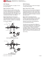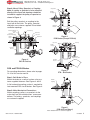
1
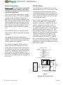
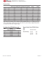
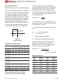
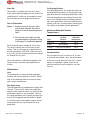
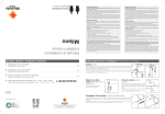
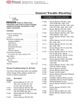
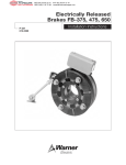
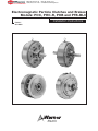
MEX (55) 53 63 23 31
DIST. AUTORIZADO QRO (442) 1 95 72 60
®
MTY (81) 83 54 10 18
[email protected]
Electromagnetic Particle Clutches and Brakes
Models: POC, PHC-R, POB and PTB-BL3
P-223-1
819-0368
Installation Instructions
MEX (55) 53 63 23 31
DIST. AUTORIZADO QRO (442) 1 95 72 60
®
MTY (81) 83 54 10 18
[email protected]
Contents
Introduction . . . . . . . . . . . . . . . . . . . . . . . . . . . 2
Installation Instructions . . . . . . . . . . . . . . . . 3-6
Electrical Data . . . . . . . . . . . . . . . . . . . . . . . . . 7
Overhung Load Data . . . . . . . . . . . . . . . . . . . 8
Start Up . . . . . . . . . . . . . . . . . . . . . . . . . . . . . . 9
Maintenance . . . . . . . . . . . . . . . . . . . . . . . . . . 9
Mechanical Data . . . . . . . . . . . . . . . . . . . . . . 10
Dimensions . . . . . . . . . . . . . . . . . . . . . . . . 11-16
Warranty . . . . . . . . . . . . . . . . . . . . . . Back Page
Failure to follow these
instructions may result in product damage,
equipment damage, and serious or fatal
injury to personnel.
Make sure all power is turned
off to this equipment when installing, as
injury (or even death) may result from contact
with live wires or rotating shafts.
2
Warner Electric • 800-825-9050
Introduction
This service manual provides information
required for installing, wiring, and maintaining
Warner Electric Magnetic Particle clutches and
brakes. Dimensions and specifications are also
included. The models covered in this service
manual include POC and PHC-R clutches and
POB and PTB brakes. For selection information,
please refer to your Warner Electric Tension
Control Sytems Catalog.
Warner Electric Magnetic Particle clutches and
brakes provide smooth and controllable torque
for a variety of torque and tension control applications. They also provide excellent performance for cycling and positioning applications.
Quick response is achieved by applying full
rated voltage. Lower voltage can be applied for
softer engagements. Extremely accurate tension
control can be achieved with an appropriate
Warner Electric tension control for electric
brakes and clutches.
819-0368
MEX (55) 53 63 23 31
DIST. AUTORIZADO QRO (442) 1 95 72 60
®
MTY (81) 83 54 10 18
[email protected]
Installation Instructions
Introduction
Verify the model of your clutch or brake by
checking the label before proceeding with these
instructions. POC and PHC-R designate clutch
models and POB and PTB are brakes. All models of POC clutches are face mounted (except
size 80, which is foot mounted) and have male
input and output shafts. See Figures 1 and 2.
The PHC-R clutch is designed to be shaft
mounted and is ideal for "parallel shaft" applications. It has a hollow bore and slides on the output shaft. An input hub with flange is provided
for mounting a pulley or sprocket. An integral
fan rotates with the input for additional cooling.
See Figure 3.
POB and PTB-BL3 brakes are face mounted
with male input shafts. Like the POC's, only the
size 80 is foot mounted. The major difference
between PTB-BL3 and POB brakes is that PTBBL3's utilize a patented heat pipe cooling
method that provides heat dissipation several
times greater than conventional cooling. See
Figures 4, 5, and 6 for mounting information on
POB's and PTB-BL3's.
Pre-Mounting
Note: Unit performance can be affected by
prolonged exposure to humid environments.
Please store in a dry location.
during shipping, making rotation difficult. This
is easily remedied by turning the unit upside
down and gently tapping the housing to
loosen the powder. Do not hit shaft. See
page 10 for nominal drag torque values.
3. Make sure the location chosen for mounting
will not expose the unit to water or oil. If
water or oil enters the powder cavity, performance may be affected. If the unit is
mounted next to a gearbox, special care
should be taken to prevent oil from working
its way into the unit.
4. If couplings are to be used in the drive system, the mounting surface must properly
locate the housing to ensure alignment is
within coupling tolerances.
5. When connections are made with pulleys or
sprockets, the overhung load must be verified to be within rating. See page 8 for allowable overhung load information.
Mounting
Note: Do not use excessive force when mounting couplings, pulleys, or sprockets on shafts.
Note: For proper function, magnetic particle
units must be mounted so the shaft is horizontal.
Use the proper mounting method described for
the model being installed.
Note: The equipment covered by this service
manual must be installed in accordance with
these instructions. Failure to do so may damage the equipment and void the warranty.
1. Remove the Magnetic Particle unit from its
shipping carton and inspect it thoroughly to
ensure that it has arrived in good condition.
When handling, please take care not to damage the unit’s lead wires or terminal block.
2. Check the input shaft/hub to make sure it
can be rotated by hand. On clutch assemblies, hold the output stationary while turning
the input. The powder inside the unit may
settle due to shock and vibration incurred
Warner Electric • 800-825-9050
819-0368
3
MEX (55) 53 63 23 31
DIST. AUTORIZADO QRO (442) 1 95 72 60
®
MTY (81) 83 54 10 18
[email protected]
POC Clutches
PHC-R Clutches
For mounting dimensions, see pages 12-13 of
this service manual.
For mounting dimensions, please refer to page
11 of this service manual.
Step 1: Bolt Clutch in Place
Mount the clutch to a vertical surface, using
customer supplied fasteners. For models larger
than size 5, the housing must be secured on
both input and output sides. See Figure 1. A flat
horizontal mounting surface is required for foot
mounted size 80 clutches. See Figure 2.
Step 1: Secure Clutch to Shaft
Slide the clutch on the shaft that is being driven
by the clutch. Secure the clutch with customer
supplied locking collars or other suitable means.
(Mounting the clutch on the shaft that is driving
the clutch is acceptable, but doing so increases
total load inertia.)
Step 2: Make Mechanical Connections
Mount couplings, pulleys, or sprockets to the
male shafts per the manufacturers' recommendations. The pulleys, sprockets, and couplings
are customer supplied.
Step 2: Attach Antirotation Restraint
Since this is a shaft mounted unit with a stationary field supported by bearings, the field must
be restrained to prevent bearing drag from
pulling on the lead wires. Restraining device
must not preload the bearing.
Capscrews
Flexible Coupling
Mounting Bracket
The field can be restrained with a holding arm
attached to the tapped holes in the field housing
or with capscrews through a mounting bracket
as shown in Figure 3. If bolts are used, first
hand tighten the bolt just enough to take out the
clearance under the head of the capscrew. Then
tighten the locking nut while preventing the bolt
from turning.
Figure 1*
POC Clutches (Except POC-80)
Flexible Coupling
Capscrews
Figure 2*
POC-80 (Foot Mount)
*Note: Shaded items are customer supplied.
4
Warner Electric • 800-825-9050
819-0368
MEX (55) 53 63 23 31
DIST. AUTORIZADO QRO (442) 1 95 72 60
®
MTY (81) 83 54 10 18
[email protected]
Step 3: Mount Pulley, Sprocket, or Coupling
Note: If a pulley or sprocket is to be attached
directly to the input hub, bearings should be
installed to support the pulley or sprocket as
shown in Figure 3.
Bolt the pulley, sprocket, or coupling to the
input hub of the clutch. The pulley, sprocket,
and bolts are customer supplied. Do not block
ventilation openings.
Ventilation Openings
Capscrews
Flexible
Coupling
Mounting
Bracket
Field Housing
Locking
Nuts
Capscrews
(Field Restraining)
Input Pulley
Capscrews
Output
Pulley
Pillow Block
Figure 4*
POB Brakes (Except POB-80)
Capscrews
Heat Pipe
Flexible
Coupling
Mounting
Bracket
Figure 3*
PHC-R Clutches
Electric Blower
Single-Phase 110V
Mounting
Bracket
POB and PTB-BL3 Brakes
Figure 5*
PTB – BL3 Brakes
For mounting dimensions, please refer to pages
14-16 of this service manual.
Step 1: Bolt Brake in Place
Mount the brake to a vertical surface using customer supplied fasteners. See Figures 4 and 5.
A flat horizontal mounting surface is required for
foot mounted POB size 80 brakes. See Figure 6.
Flexible
Coupling
Step 2: Make Mechanical Connections
Mount couplings, pulleys, or sprockets to the
male shafts per the manufacturers' recommendations. The pulleys, sprockets, and couplings
are customer supplied.
Figure 6*
POB-80 (Foot Mount)
*Note: Shaded items are customer supplied.
Warner Electric • 800-825-9050
819-0368
5
MEX (55) 53 63 23 31
DIST. AUTORIZADO QRO (442) 1 95 72 60
®
MTY (81) 83 54 10 18
[email protected]
Electrical Connections
PTB-BL3 Wiring
To avoid injury (or even death),
always make certain all power is off before
attempting to install or service the control or
any electrical equipment.
The PTB-BL3 units are offered with a normally
closed thermal switch. This switch can be used
to protect the unit from overheating. It is not
recommended that this switch be connected in
series with the unit, because the opening of the
thermal switch on the output side of the control
may damage the control.
The clutch and brakes operate on DC voltage.
Warner Electric offers a full line of AC powered
controls to meet the needs of almost every
application. The service and installation instructions included with each Warner Electric control
show the proper electrical connections for the
units. Do not use the varistor supplied with the
unit if you are using a Warner Electric control.
Warner Electric controls have built in suppression.
Each PTB-BL3 brake has a cooling fan and a
thermal switch. Connect these items according
to Figure 7.
Use appropriate terminal connectors when
wiring to the terminal block. After connecting the
terminal, cover it with the attached rubber cap
so that no bare wire is exposed.
After wiring your Magnetic Particle clutch or
brake, confirm that the control circuit is functioning. Without rotating the input shaft, check
for voltage at the unit when the control output is
turned on. If appropriate, set the current for the
proper output. Your magnetic particle unit is
now ready for operation. For additional information on start up and maintenance, see page 9 of
this manual.
Figure 7 shows one possible way of using the
switch in a shutdown circuit. Under normal
operation, when power is applied to the circuit,
voltage is applied to the interval-on-relay, KS.
This momentarily closes contacts KSA. This in
turn applies voltage to relay KT. This double pole
double throw relay closes contacts KTA1, and
KTB1 and opens contacts KTA2 and KTB2. These
contacts will remain in this state unless power is
removed or the thermal switch opens. If the
switch opens, the thermal shutdown indicator
will be activated and the state of KTB1 and /or
KTB2 will shut down the system. After correcting
the cause of the thermal shutdown, the thermal
reset button will reset the shutdown circuit and
power up the system.
Terminal Block Wiring
To alarm or
Shutdown circuit
S
S
M
115 VAC
M
C
DC24V
C
Thermal Switch
Fan Motor
Brake Coil
Typical Shutdown Circuit
Note: Select relays with appropiate voltage rating for circuit.
KSA
Man.
Thermal
Reset
KTA1
KTB1
KTB2
KTA2
To control
circuit
or other
shut down
method
KS
S1
Thermal
Shutdown
Indicator
R
KS
=
S2
Power
AC
or DC
Thermal
Switch
KT
Interval On Relay
KT
= DPDT
Relay
Figure 7
Wiring (PTB-BL3 Brake Only)
6
Warner Electric • 800-825-9050
819-0368
MEX (55) 53 63 23 31
DIST. AUTORIZADO QRO (442) 1 95 72 60
®
MTY (81) 83 54 10 18
[email protected]
Electrical Data
Unit Size
Voltage
Resistance
Amperes
Watts
Torque Build Up Torque Decay
[ohms @ 75° F (25°C)] [@ 75° F (25°C)] [@ 75° F (25°C)]
(msec)
(msec)
0.3
24
35.6
.674
16.2
78
6
0.6
24
21.1
1.14
27.4
84
9
1.2
24
20.6
1.16
28.0
147
16
2.5
24
15.8
1.52
36.5
175
21
5
24
8.80
2.74
65.7
271
28
10
24
9.00
2.68
64.2
448
43
20
24
7.20
3.34
80.3
536
66
40
24
5.10
4.66
112
680
100
80
24
4.30
5.57
134
1310
300
Note: Build up time equals time for torque to build to approximately 63.2% of steady state value
after a step change in voltage. Decay time equals time for current to drop to approximately 36.8%
of steady state value after a voltage change.
Fan Motor Data (PTB-BL3 Brake only)
Size
Voltage
(single phase 60 hertz)
Wattage
2.5
115 VAC
20
5
115 VAC
38
10
115 VAC
38
20
115 VAC
38
Warner Electric • 800-825-9050
Thermal Switch Data (PTB-BL3 Brake
only)
Type:
Normally Closed
Current Rating:
24 VAC
18 A
115 VAC
18 A
230 VAC
13 A
819-0368
7
MEX (55) 53 63 23 31
DIST. AUTORIZADO QRO (442) 1 95 72 60
®
MTY (81) 83 54 10 18
[email protected]
Overhung Load Data
Note: Shaft extensions are not recommended.
When an overhung load (side load) is applied to
the shaft, verify that this load does not exceed
the maximum allowable. You will need to know
your operating speed and where your load is
applied to the shaft (See dimension 'A', Figure
8). For your speed, determine the speed coefficient from the coefficient table. Also, determine
the allowable overhung load from the chart
based on dimension 'A'. Multiply the load from
the chart times the speed coefficient to determine the allowable load for your application.
For most applications, the overhung load is
caused by pulleys or sprockets. The smaller the
pitch diameter (P.D.) of the pulley or sprocket,
the higher the belt tension, and therefore the
higher the overhung load. To determine the minimum pulley diameter for your application, use
the following equation:
Min. P.D.(in.) =
T - Torque (lb. ft.) This is the torque actually
being transmitted, not necessarily the maximum
torque capacity of the unit.
K - Safety factor for the tension in the type of
drive.
A (inches)
Use:
R - Allowable Overhung Load from table.
Figure 8
Overhung Load
Allowable Overhung Load
Type
A
R
A
R
A
R
(In.) (Lbs.) (In.) (Lbs.) (In.) (Lbs.)
POC/POB-0.3
.40
30
.50
28
.90
22
POC/POB-0.6
.40
45
.50
42
1.0
29
POC/POB-1.2
.40
52
.70
43
1.4
31
POC/POB-2.5
PTB2.5-BL3
.40
88
.90
67
1.7
48
POC/POB-5
PTB-5BL3
.40
204
1.1
136
2.2
93
POC/POB-10
PTB-10BL3
POC/POB-20
PTB-20BL3
.40
313
1.3
235
2.6
159
.40
379
1.4
265
2.8
198
POC/POB-40
.40
581
1.8
432
3.6
POC/POB-80
.40
860
2.2
648
4.3
Example: Determine the minimum sprocket
diameter that can be used on a POB-5.
Dimension A is 1.11 inches, required torque is
20 lb. ft. and the speed is 600 RPM.
Min. P.D.(in.) = 24 x 20 x 1.5
1.2 x 136
= 4.4 inch minimum P.D.
Speed Coefficient
Speed
coefficient
Speed
(rpm)
Speed
coefficient
50
2.74
1000
1.00
100
2.18
1200
0.95
200
1.72
1400
0.89
324
400
1.37
1600
0.86
498
600
1.20
1800
0.82
800
1.09
2000
0.80
Note: This table is based on 1000 rpm and
6000 hours bearing life. Also, this table
assumes that no thrust load is applied.
Warner Electric • 800-825-9050
1.2 to 1.5 for sprockets
2 to 4 for belts
C - Speed coefficient from table.
R (lbs)
8
24 T K
CR
Speed
(rpm)
819-0368
MEX (55) 53 63 23 31
DIST. AUTORIZADO QRO (442) 1 95 72 60
®
MTY (81) 83 54 10 18
[email protected]
Start Up
The powder in magnetic particle units sometimes settles during shipping and will need to be
redistributed. A simple run in procedure should
be performed to ensure proper performance.
Run in Procedure
Notes: 1. Before running in the unit, make
sure it does not bind. See step 2
(Page 3) of the Premounting instructions.
2. For clutches, the output must be
secured properly to prevent turning
if full torque is accidentally applied.
Set the control output voltage for 5 to 6 volts.
Turn off the control and run the input for one
minute. Then run the input at a speed close to,
but not exceeding, 1000 RPM. Cycle the unit at
5 or 6 volts for five seconds on and ten seconds
off. Repeat for 20 cycles.
When the powder is redistributed properly, the
torque will be consistent and proportional to
current.
Cycling Applications
In cycling applications, the speed and inertia of
the load and the frequency of starting and stopping determines the heat generated. Refer to the
selection procedure in the catalog to verify that
the unit can handle the thermal energy generated in your application. Do not increase the input
speed, cycle rate, or inertia without checking the
units ability to dissipate the heat generated.
Maximum Allowable Surface
Temperatures
Type
Cooling
System
Maximum
Allowable
Temperature
POC/POB
Natural
176° F
Self-ventilated
176° F
Heat Pipe with Blower
194° F
PHC-R
PTB-BL3
Contamination
Do not expose the unit to water or oil. If water
or oil enters the powder cavity, the performance
of the unit may be affected. If the unit is mounted next to a gearbox, special care must be
taken to prevent oil from working its way into
the unit.
Maintenance
Heat
Overheating occurs when the heat generated
exceeds the heat dissipation of the unit. Please
refer to the following table for maximum allowable surface temperatures.
Slip Applications
The heat generated is proportional to torque and
slip rpm. Care must be taken when adjusting
torque on the control to make sure that unit heat
dissipation capacity is not exceeded. Refer to
the sizing procedure in the catalog to make sure
the unit has adequate heat dissipation capability. Do not increase slip speed or torque without
verifying that the unit can dissipate the heat
generated.
Warner Electric • 800-825-9050
819-0368
9
MEX (55) 53 63 23 31
DIST. AUTORIZADO QRO (442) 1 95 72 60
®
MTY (81) 83 54 10 18
[email protected]
Mechanical Data
Part
Number
Nominal
Torque
(lb. ft.)
Nominal Drag
Torque
(lb. ft.)
Maximum
Speed
(rpm)
Inertia
Input
(lb. ft.2 )
Output
(lb. ft.2 )
Weight
(lbs.)
POC 0.3
5401-270-211
2.1
.065
1800
.0128
.00477
5.5
POC 0.6
5401-270-221
4.3
.13
1800
.0173
.00570
7.9
POC 1.2
5401-270-231
8.6
.26
1800
.0304
.0104
12
POC 2.5
5401-270-241
18
.54
1800
.0973
.0387
22
POC 5
5401-270-251
36
1.1
1800
.0249
.114
38
POC 10
5401-270-261
72
2.2
1800
1.04
.437
77
POC 20
5401-270-271
144
4.3
1800
2.23
1.19
128
POC 40
5401-270-281
289
8.7
1800
5.93
3.08
220
POC 80
5401-270-291
578
17
1500
23.5
15.2
551
PHC-0.6R
5401-270-321
4.3
.13
1800
.0223
.00712
9.3
PHC-1.2R
5401-270-331
8.6
.26
1800
.0392
.0171
13
PHC-2.5R
5401-270-341
18
.54
1800
.126
.0494
22
PHC-5R
5401-270-351
36
1.1
1800
.323
.0138
38
PHC-10R
5401-270-361
72
2.2
1500
1.42
.617
95
PHC-20R
5401-270-371
144
4.3
1500
3.01
1.30
154
POB 0.3
5401-169-211
2.1
.065
1800
.0128
5.3
POB 0.6
5401-169-221
4.3
.13
1800
.0173
7.5
POB 1.2
5401-169-231
8.6
.26
1800
.0304
11.5
POB 2.5
5401-169-241
18
.54
1800
.0973
24.3
POB 5.0
5401-169-251
36
1.1
1800
.0249
35.3
POB 10
5401-169-261
72
2.2
1800
1.04
72.8
POB 20
5401-169-271
144
4.3
1800
2.23
106
POB 40
5401-169-281
289
8.7
1800
5.93
176
POB 80
5401-169-291
578
17
1500
23.5
573
PTB-2.5BL3
5401-169-141
18
.54
1800
.0973
24
PTB-5BL3
5401-169-151
36
1.1
1800
.249
38
PTB-10BL3
5401-169-161
72
2.2
1800
1.04
76
PTB-20BL3
5401-169-171
144
4.3
1500
2.23
114
Model
10
Warner Electric • 800-825-9050
819-0368
MEX (55) 53 63 23 31
DIST. AUTORIZADO QRO (442) 1 95 72 60
®
MTY (81) 83 54 10 18
[email protected]
PHC-R Dimensions
B
C
L (6 Holes)
30°
300 mm
(11.8 in.)
4mm
(.16 in.)
K
F E A
D
D
Input Hub
G
Ventilation
Opening
H
I
J
PHC-R Dimensional Data
Note: All dimensions are nominal unless otherwise noted.
Bore Dimensions
Model
A
mm
(In.)
B
mm
(in.)
C
mm
(in.)
D
mm
(in.)
PHC-
134
92
4
25.5
0.6R
(5.28)
(3.62)
(0.16)
(1.00)
PHC-
152
96
4
25
1.2R
(5.98)
(3.78)
(0.16)
(0.98)
PHC-
182
132
5
45
2.5R
(7.17)
(5.20)
(0.20)
(1.77)
PHC5R
PHC10R
PHC20R
219
148
4
40
(8.62)
(5.83)
(0.16)
(1.57)
290
183.5
(11.42) (7.22)
335
222
(13.19) (8.74)
E
mm
(in.)
F
G
mm
89
50.000
1.9685
50.000
1.9685
12.018 0.4731 4.028
0.1586
13.75
0.5413
(3.50) 49.975
1.9675
49.975
1.9675
12.000 0.4724 4.010
0.1579
13.50
0.5315
(in.)
mm
H
(in.)
mm
I
(in.)
mm
J
(in.)
mm
(in.)
45.000
1.7717
70.000
2.7559
15.018 0.5913 5.028
0.1980
17.25
0.6791
(3.50) 44.975
1.7707
69.970
2.7547
15.000 0.5906 5.010
0.1972
17.00
0.6693
89
70.000
2.7559
70.000
2.7559
25.021 0.9851 7.035
0.2770
28.25
1.1122
(5.51) 69.970
2.7547
69.670
2.7429
25.000 0.9843 7.013
0.2761
28.00
1.1024
140
87.000
3.4252
87.000
3.4252
35.025 1.3789 10.035 0.3951
38.75
1.5256
(6.50) 86.965
3.4238
86.965
3.4238
35.000 1.3780 10.013 0.3942
38.50
1.5157
165
K
Thrd. Depth
Size
mm
(in.)
M4
M5
M6
M8
6
60
190 105.000 4.1339 110.000 4.3307
45.025 1.7726 12.043 0.4741
48.75
1.9193 M10
(0.24)
(2.36)
(7.48) 104.965 4.1325 109.965 4.3293
45.000 1.7717 12.016 0.4731
48.50
1.9094
9
75
220 130.000 5.1181 130.000 5.1181
55.030 2.1665 15.043 0.5922
60.25
2.3720 M10
(0.35)
(2.95)
(8.66) 129.960 5.1165 129.960 5.1165
55.000 2.1654 15.016 0.5912
60.00
2.3622
Bolt
Thrd.
Circle Size
mm (in.)
6
60
(0.24)
(2.362)
6
55
(0.24)
(2.165)
10
80
(0.39)
(3.150)
10
102
(0.39)
(4.016)
13
120
(0.51)
(4.724)
15
150
(0.59)
(5.906)
L
Depth
mm
(in.)
M4
6
60
(0.24)
(2.362)
M4
8
80
(0.31)
(3.150)
M6
9
80
(0.35)
(3.150)
M8
10
102
(0.39)
(4.016)
M8
M10
Bolt
Circle
mm (in.)
10
120
(0.39)
(4.724)
13.5
150
(0.53)
(5.906)
Note: This is a stationary field clutch. The tapped holes "L" in the field are for securing the housing to prevent it from rotating.
See instaltion instructions.
Do not block ventilation openings when mounting.
Warner Electric • 800-825-9050
819-0368
11
MEX (55) 53 63 23 31
DIST. AUTORIZADO QRO (442) 1 95 72 60
®
MTY (81) 83 54 10 18
[email protected]
POC Dimensional Data
Note: All dimensions are nominal unless otherwise noted.
Model
D
mm
(in.)
E
mm
(in.)
F
mm
(in.)
G
mm
inches
Shaft Dimensions
H
I
mm
inches mm
inches
A
mm
(in.)
B
mm
(in.)
C
mm
(in.)
POC-0.3
120
(4.72)
147
(5.79)
23
(0.91)
87
11
65
42.000 1.6535
(3.43) (0.43) (2.56) 41.975 1.6526
10.000 0.3937
9.985 0.3931
4.024
4.012
POC-0.6
134
(5.28)
155
(6.10)
26
(1.02)
90
10
70
42.000 1.6535
(3.54) (0.39) (2.76) 41.975 1.6526
12.000 0.4724
11.982 0.4717
POC-1.2
152
(5.98)
188
(7.40)
34.5
(1.36)
106
13
80
42.000 1.6535
(4.17) (0.51) (3.15) 41.975 1.6526
POC-2.5
182
(7.17)
227.5
(8.96)
43
(1.69)
POC-5
219
(8.62)
L
Depth No. of Bolt
mm Holes Circle
(in.)
mm
(in.)
J
mm
(in.)
K
mm
(in.)
0.1584
0.1580
4
(0.16)
2.5
(0.10)
M5
10
(0.39)
6x2
64
(2.520)
4.024
4.012
0.1584
0.1580
4
(0.16)
2.5
(0.10)
M5
11
(0.43)
6x2
64
(2.520)
15.000 0.5906
14.982 0.5898
5.024
5.012
0.1978
0.1973
5
(0.20)
3
(0.12)
M6
13
(0.51)
6x2
64
(2.520)
123.5
15
93.5 55.000 2.1654
(4.86) (0.59) (3.68) 54.970 2.1642
20.000 0.7874
19.979 0.7866
5.024
5.012
0.1978
0.1973
5
(0.20)
3
(0.12)
M6
13
(0.51)
6x2
78
(3.071)
284
57
(11.18) (2.24)
151
23
105 74.000 2.9134
(5.94) (0.91) (4.13) 73.970 2.9122
25.000 0.9843
24.979 0.9834
7.030
7.015
0.2768
0.2762
7
(0.28)
4
(0.16)
M6
13
(0.51)
6x2
100
(3.937)
POC-10
290
348
67
(11.42) (13.70) (2.64)
192
25
142 100.000 3.9370
(7.56) (0.98) (5.59) 99.965 3.9356
30.000 1.1811
29.979 1.1803
7.030
7.015
0.2768
0.2762
7
(0.28)
4
(0.16)
M10
18
(0.71)
6x2
140
(5.512)
POC-20
335
382
71
(13.19) (15.04) (2.80)
216
25
166 110.000 4.3307
(8.50) (0.98) (6.54) 109.965 4.3293
35.000 1.3780 10.030
34.975 1.3770 10.015
0.3949
0.3943
8
(0.31)
4.5
(0.18)
M10
18
(0.71)
6x2
150
(5.906)
POC-40
395
490
92
278
33
212 130.000 5.1181
(15.55) (19.29) (3.62) (10.94) (1.30) (8.35) 129.960 5.1165
45.000 1.7717 12.036
44.975 1.7707 12.018
0.4739
0.4731
8
(0.31)
4.5
(0.18)
M12
20
(0.79)
8x2
200
(7.874)
Thread
Size
* Air inlet for optional forced air cooling. Consult factory.
12
Warner Electric • 800-825-9050
819-0368
MEX (55) 53 63 23 31
DIST. AUTORIZADO QRO (442) 1 95 72 60
®
MTY (81) 83 54 10 18
[email protected]
POC Dimensions
L
10° 10°
Terminals
L
10° 10°
Terminals
4x3/8 Conduit
End View (POC 0.3)
End View (POC-40)
30°
B
D
L
C
E
C
E
F
m
0 m in)
30 1.8
(1
G
G
I
J
Output
A
Input
K
H
End View (POC 0.6, 1.2,
2.5, 5.0, 10, 20)
POC – 80
Terminal blocks
110
(4.33)
100
(3.94)
322.5
(12.70)
197.5
(7.78)
88
(346)
645
(25.40)
322.5
(12.70)
197.5
(7.78)
88
(346)
110
(4.33)
100
(3.94)
Ø480
(18.90)
560
(22.05)
515
(20.28)
(
18.036 .7101
18.018 .7094
275.0 10.83
274.5 (10.81)
Input
Output
)
12
(.47)
90
(3.54)
145
(5.71)
145
(5.71)
390
(15.35)
90
(3.54)
Warner Electric • 800-825-9050
6
(.24)
25
(.98)
4-Ø21 (.83)
90
(3.54)
(
)
65.000 2.5591
64.970 2.5579
90
140 (3.54)
140
(5.51)
(5.51)
350
(13.78)
819-0368
13
MEX (55) 53 63 23 31
DIST. AUTORIZADO QRO (442) 1 95 72 60
MTY (81) 83 54 10 18
[email protected]
®
POB Dimensions
L
10° 10°
Terminals
10° 10°
L
Terminals
4x3/8 Conduit*
End View (POB-0.3)
End View (POB-40)
30°
L
B
D
C
E
F
3
(1100 m
.8 m
in)
A
G
I
K
J
H
End View (POB-0.6, 1.2,
2.5, 5.0, 10, 20)
POB-80
Terminal blocks
110
(4.33)
100
(3.94)
485
(19.09)
322.5
(12.70)
197.5
(7.78)
88
(346)
162.5
(6.40)
53
(2.09)
Ø480
(18.90)
560
(22.05)
515
(20.28)
(
18.036 .7101
18.018 .7094
275.0 10.83
274.5 10.81
(
)
)
12
(.47)
90
(3.54)
14
145
(5.71)
145
(5.71)
390
(15.35)
Warner Electric • 800-825-9050
6
(.24)
90
(3.54)
25
(.98)
4-Ø21 (.83)
(
)
65.000 2.5591
64.970 2.5579
90
(3.54)
140
140
(5.51) (5.51)
350
(13.78)
90
(3.54)
819-0368
MEX (55) 53 63 23 31
DIST. AUTORIZADO QRO (442) 1 95 72 60
®
MTY (81) 83 54 10 18
[email protected]
POB Dimensional Data
Note: All dimensions are nominal unless otherwise noted.
Model
POB-0.3
POB-0.6
POB 1.2
POB 2.5
POB 5.0
POB 10
POB 20
POB-40
A
mm
(in.)
B
mm
(in.)
C
mm
(in.)
D
mm
(in.)
E
mm
(in.)
F
mm
(in.)
mm
(in.)
120
(4.72)
134
(5.28)
152
(5.98)
182
(7.17)
219
(8.62)
290
(11.42)
335
(13.19)
395
(15.55)
105
(4.13)
109
(4.29)
130.5
(5.14)
155
(6.10)
189
(7.44)
233.5
(9.19)
263.5
(10.37)
330
(12.99)
23
(0.91)
26
(1.02)
34.5
(1.36)
43
(1.69)
57
(2.24)
67
(2.64)
71
(2.80)
92
(3.62)
75
(2.95)
76.5
(3.01)
89.5
(3.52)
103
(4.06)
122.5
(4.82)
155.5
(6.12)
180.5
(7.11)
224
(8.82)
11
(0.43)
10
(0.39)
13
(0.51)
15
(0.59)
23
(0.91)
25
(0.98)
25
(0.98)
33
(1.30)
64
(2.52)
66.5
(2.62)
76.5
(3.01)
88
(3.46)
99.5
(3.92)
130.5
(5.14)
155.5
(6.12)
191
(7.52)
42.000
41.975
42.000
41.975
42.000
41.975
55.000
54.970
74.000
73.970
100.000
99.965
110.000
109.965
130.000
129.960
1.6535
1.6526
1.6535
1.6526
1.6535
1.6526
2.1654
2.1642
2.9134
2.9122
3.9370
3.9356
4.3307
4.3293
5.1181
5.1165
Warner Electric • 800-825-9050
G
Shaft Dimensions
H
I
mm
(in.)
mm
10.000
9.985
12.000
11.982
15.000
14.982
20.000
19.979
25.000
24.979
30.000
29.979
35.000
34.975
45.000
44.975
0.3937
0.3931
0.4724
0.4717
0.5906
0.5898
0.7874
0.7866
0.9843
0.9834
1.1811
1.1803
1.3780
1.3770
1.7717
1.7707
4.024
4.012
4.024
4.012
5.024
5.012
5.024
5.012
7.030
7.015
7.030
7.015
10.030
10.015
12.036
12.018
(in.)
J
mm
(in.)
K
mm
(in.)
0.1584
0.1580
0.1584
0.1580
0.1978
0.1973
0.1978
0.1973
0.2768
0.2762
0.2768
0.2762
0.3949
0.3943
0.4739
0.4731
4
(0.16)
4
(0.16)
5
(0.20)
5
(0.20)
7
(0.28)
7
(0.28)
8
(0.31)
8
(0.31)
2.5
(0.10)
2.5
(0.10)
3.0
(0.12)
3.0
(0.12)
4.0
(0.16)
4.0
(0.16)
4.5
(0.18)
4.5
(1.18)
Thread
Size
M5
M5
M6
M6
M6
M10
M10
M12
Depth
mm
(in.)
10
(0.39)
11
(0.43)
13
(0.51)
13
(0.51)
13
(0.51)
18
(0.71)
18
(0.71)
20
(0.79)
L
No. of
Holes
6
6
6
6
6
6
6
8
Bolt
Circle
mm
(in.)
64
(2.520)
64
(2.520)
64
(2.520)
78
(3.071)
100
(3.937)
140
(5.512)
150
(5.906)
200
(2.520)
819-0368
15
MEX (55) 53 63 23 31
DIST. AUTORIZADO QRO (442) 1 95 72 60
®
MTY (81) 83 54 10 18
[email protected]
PTB Dimensions
B
F
G
N
C
E
D
Terminal Block
I
A
K
H
M
Electric Blower,
Single-Phase 110 VAC
L
J
PTB Dimensional Data
Note: All dimensions are nominal unless otherwise noted.
Shaft Dimensions
Model
I
N
A
B
C
D
E
F
G
H*
mm
mm
mm
mm
mm
mm
mm
mm
(in.)
(in.)
(in.)
(in.)
(in.)
(in.)
(in.)
(in.)
182
221.5
169.5
43
15
43
38
120
55.000
2.1654
20.000
0.7874
5.024
(7.17)
(8.72)
(6.67)
(1.69)
(0.59)
(1.69)
(1.50)
(4.72)
54.970
2.1642
19.979
0.7866
5.012
mm
J
(in.)
mm
K
(in.)
mm
L
M
mm
mm
(in.)
0.1978
0.1973
(in.)
Depth
Bolt
Thread
mm
Circle
(in.)
Size
(in.)
mm
5
3
M6
13
78
(0.20)
(0.12)
(0.51)
(3.071)
(in.)
PTB2.5BL3
PTB-
219
274.5
208
61.5
23
57
47
150
74.000
2.9134
25.000
0.9843
7.030
0.2768
7
4
5BL3
(8.62)
(10.81)
(8.19)
(2.42)
(0.91)
(2.24)
(1.85)
(5.91)
73.970
2.9122
24.979
0.9834
7.015
0.2762
(0.28)
(0.16)
290
335
257
PTB10BL3
PTB20BL3
(11.42) (13.19) (10.12)
335
352.5
61.5
25
67
56
150
(2.42)
(0.98)
(2.64)
(2.20)
(5.91)
269.5
61.5
25
71
60
(13.19) (13.88) (10.61)
(2.42)
(0.98)
(2.80)
(2.36)
100.000 3.9370
30.000
1.1811
7.030
0.2768
7
4
99.965
29.979
1.1803
7.015
0.2762
(0.28)
(0.16)
3.9356
110.000 4.3307
35.000
1.3780 10.030
0.3949
8
4.5
(5.91) 109.965 4.3293
34.975
1.3770 10.015
0.3943
(0.31)
(0.18)
150
M6
M10
M10
13
100)
(0.51)
(3.937)
18
140
(0.71)
(5.572)
18
150
(0.71)
(5.906)
* Adjacent symbol denotes shape of fan.
16
Warner Electric • 800-825-9050
819-0368
MEX (55) 53 63 23 31
DIST. AUTORIZADO QRO (442) 1 95 72 60
®
Warner Electric • 800-825-9050
MTY (81) 83 54 10 18
[email protected]
819-0368
17
MEX (55) 53 63 23 31
DIST. AUTORIZADO QRO (442) 1 95 72 60
®
MTY (81) 83 54 10 18
[email protected]
Warranty
Warner Electric LLC warrants that it will repair or replace (whichever it deems advisable) any
product manufactured and sold by it which proves to be defective in material or workmanship
within a period of one (1) year from the date of original purchase for consumer, commercial or
industrial use.
This warranty extends only to the original purchaser and is not transferable or assignable without
Warner Electric LLC’s prior consent.
Warranty service can be obtained in the U.S.A. by returning any defective product, transportation
charges prepaid, to the appropriate Warner Electric LLC factory. Additional warranty information
may be obtained by writing the Customer Satisfaction Department, Warner Electric LLC, 449
Gardner Street, South Beloit, Illinois 61080, or by calling 815-389-3771.
A purchase receipt or other proof of original purchase will be required before warranty service is
rendered. If found defective under the terms of this warranty, repair or replacement will be made,
without charge, together with a refund for transportation costs. If found not to be defective, you
will be notified and, with your consent, the item will be repaired or replaced and returned to you
at your expense.
This warranty covers normal use and does not cover damage or defect which results from
alteration, accident, neglect, or improper installation, operation, or maintenance.
Some states do not allow limitation on how long an implied warranty lasts, so the above limitation
may not apply to you.
Warner Electric LLC’s obligation under this warranty is limited to the repair or replacement of the
defective product and in no event shall Warner Electric LLC be liable for consequential, indirect,
or incidental damages of any kind incurred by reason of the manufacture, sale or use of any
defective product. Warner Electric LLC neither assumes nor authorizes any other person to give
any other warranty or to assume any other obligation or liability on its behalf.
WITH RESPECT TO CONSUMER USE OF THE PRODUCT, ANY IMPLIED WARRANTIES WHICH
THE CONSUMER MAY HAVE ARE LIMITED IN DURATION TO ONE YEAR FROM THE DATE OF
ORIGINAL CONSUMER PURCHASE. WITH RESPECT TO COMMERCIAL AND INDUSTRIAL
USES OF THE PRODUCT, THE FOREGOING WARRANTY IS IN LIEU OF AND EXCLUDES ALL
OTHER WARRANTIES, WHETHER EXPRESSED OR IMPLIED BY OPERATION OF LAW OR
OTHERWISE, INCLUDING, BUT NOT LIMITED TO, ANY IMPLIED WARRANTIES OF
MERCHANTABILITY OR FITNESS.
Some states do not allow the exclusion or limitation of incidental or consequential damages, so
the above limitation or exclusion may not apply to you. This warranty gives you specific legal
rights and you may also have other rights which vary from state to state.
Changes in Dimensions and Specifications
All dimensions and specifications shown in Warner Electric catalogs are subject to change without
notice. Weights do not include weight of boxing for shipment. Certified prints will be furnished
without charge on request to Warner Electric.
Warner Electric LLC
449 Gardner Street • South Beloit, IL 61080
815-389-3771 • Fax: 815-389-2582
www.warnerelectric.com
P-223-1 819-0368 6/05
Printed in USA