1
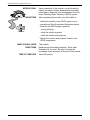
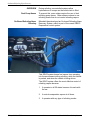
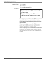
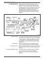
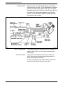
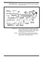
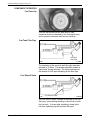
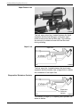
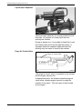
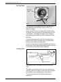
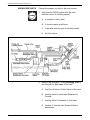
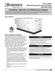
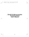
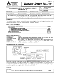
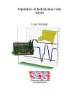
17.25
Theory Module
On-Board Refueling
Vapor Recovery
How will this module help you?
The On-Board Refueling Vapor Recovery
(ORVR) system will soon be adopted on all
vehicles sold by MMSA. By completing this
module, you will be better prepared to
diagnose and repair possible malfunctions.
SAFETY IS YOUR RESPONSIBILITY
This technical training module is for use by professional Mitsubishi Motors dealership
service technicians. The descriptions and procedures in this publication supplement
existing service manuals, technical service bulletins, and other documents provided by
Mitsubishi Motor Sales of America, Inc. (MMSA). As a result, the use of these sources
may be required to ensure a proper repair.
Within this module you will find Notes, Cautions, and Warnings. These references provide
guidance to help you do your job efficiently and safely. The definitions for these terms are
listed below.
NOTE
The purpose of a Note is to help you do your job more efficiently. A Note may
also provide additional information to help clarify a particular point or
procedure.
CAUTION
A Caution alerts you to the possibility of damage to either tools, equipment, or
to the vehicle itself. A Caution recommends that a procedure must be done in
a certain way to avoid potential problems resulting from improper technique or
method.
WARNING
A Warning alerts you to the highest level of risk. Warnings inform you that a
procedure must be done in a particular way to minimize the chances of an
accident that could result in personal injury or even loss of life.
When you see a Note, Caution, or Warning, be sure you understand the message before
you attempt to perform any part of a service procedure. Also keep in mind it is impossible
for MMSA to anticipate or evaluate every service situation a technician may encounter.
For that reason, you have the final responsibility for personal safety–yours and those
working around you. Be sure to always wear proper protective clothing and safety
equipment, use the proper tools, and follow the repair procedures as outlined in various
service publications provided by MMSA.
No part of this publication may be reproduced, stored
electronically, or transmitted in any form or by any means without
prior written approval from Mitsubishi Motor Sales of America, Inc.
MMSA reserves the right to make changes in the descriptions,
specifications, or procedures without prior notice or obligation.
Copyright © 1998 Mitsubishi Motor Sales of America, Inc.
Corporate Technical Training Department
On-Board Refueling Vapor Recovery
MODULE GOAL
OBJECTIVES
Upon completion of this module, you will be able to
identify the unique design characteristics that affect
performance, diagnosis, and maintenance of the Onboard Refueling Vapor Recovery (ORVR) system.
After completing this module, you will be able to:
· Identify the benefits of an ORVR system over a
conventional Strict Evaporative Emissions system.
· Describe the ORVR system operation:
- during refueling
- while the vehicle is parked
- while the vehicle is being driven
· Identify the location and purpose of each of the
ORVR components.
WHAT YOU WILL NEED
DIRECTIONS
TIME TO COMPLETE
Theory Module 17.25
This module.
Read through this material carefully. Study each
illustration as you read. Be able to answer the
knowledge check questions at the end of this module.
About 30 minutes.
1
Mitsubishi Motor Sales of America
On-Board Refueling Vapor Recovery
Module Signposts
Refer to the related video material for more
information.
Refer to the related publication for more
information.
Perform the related activity and answer
the related questions.
Complete the Knowledge Check to verify
your understanding of the material.
U-21
Theory Module 17.25
17.25-2
2
Mitsubishi Motor Sales of America
On-Board Refueling Vapor Recovery
OVERVIEW
During refueling, uncontrolled systems allow
hydrocarbons to escape as the vehicle tank is filled.
Hoses
• Give examples ofDual
ECUPump
applications:
To prevent this, some states require the use of dual
refueling pump hoses. Other states continue to use
refueling hoses that do not control refueling vapors.
Auto A/C
EFI
On-Board Refueling Vapor
Recovery
Auto trans
Mitsubishi has developed an On-board Refueling Vapor
Recovery System, which is part of the overall OBD-II
Evaporative control system.
U-22
17.25-3
This ORVR system keeps fuel vapors from escaping
into the environment during refueling, while the vehicle
is parked, and when the vehicle is being driven.
The ORVR system offers the most effective control of
refueling vapors because:
1. It operates in all 50 states because it travels with
the car.
2. It controls evaporative vapors at all times.
3. It operates with any type of refueling nozzle.
Theory Module 17.25
3
Mitsubishi Motor Sales of America
On-Board Refueling Vapor Recovery
APPLICATION
FUNCTION
· 99 C Galant
· 99 C Mirage
· 98 C Eclipse (except GSX)
· System controls fuel vapors at all times.
· System monitor can set DTCs and turn on MIL
in case of failure.
· Diagnosis similar to previous EVAP systems.
· New scan tool tests available to verify a repair.
U-23
17.25-4
From the drivers point of view, the ORVR system
operates like other evaporative emissions systems.
As long as the system is operating properly, the driver
will be unaware.
When a system failure occurs, the OBD-II systems
monitor can set DTCs and turn on the Malfunction
Indicator Lamp (MIL) to inform the driver.
When a malfunction occurs, system diagnosis is similar
to previous EVAP emission control systems, however
there are new scan tool tests to help you quickly verify
a repair.
Theory Module 17.25
4
Mitsubishi Motor Sales of America
On-Board Refueling Vapor Recovery
SYSTEM OPERATION
During refueling, the Fuel filler nozzle moves the
shutter valve in the fuel Vent Valve (previously called
the OLFV - Over Fill Limiter Valve). This closes the
passage between the Fuel Cutoff Valve and the LiquidVapor Separator. A small 3mm hole in the shutter
valve allows some fuel vapor from the tank to
recirculate into the fuel filler neck. This reduces the
amount of fresh air drawn into the filler neck during
refueling.
U-24
17.25-5
Pressure in tank
Leveling Valve
Fuel Shut-off Valve
Fuel Vent Valve Shutter Valve
Theory Module 17.25
As the tank is filled, pressure builds up inside the tank.
This pressure forces vapor in the tank to pass through
a “leveling valve” to a liquid-vapor separator, and then
to the canister. The canister traps the hydrocarbons
and releases clean air out of the vent valves, into the
atmosphere.
When fuel reaches a given level, the leveling valve
closes to keep liquid fuel from entering the canister.
When fuel stops flowing into the tank, the fuel shut-off
valve also closes to keep fuel from flowing back up the
filler pipe.
As the fuel tank cap is installed securely, the shutter
valve in the fuel vent valve opens the passage
between the fuel cut-off valve and the liquid vapor
separator.
5
Mitsubishi Motor Sales of America
On-Board Refueling Vapor Recovery
Vehicle Parked
When fuel tank is full, the leveling valve is closed by
the fuel level in the tank. If fuel temperature and vapor
pressure increase when parked, fuel vapor can pass
through the fuel cut-off valve, fuel check valve, the fuel
vent valve, the liquid-vapor separator, and into the
canister. The liquid vapor separator keeps liquid fuel
from entering the canister.
U-25
17.25-6
Vent to atmosphere
Fuel Check Valve
The canister traps the hydrocarbons and releases the
clean air that is left, out of the vent valves into the
atmosphere.
If pressure within the tank becomes too high, the
check valve opens, allowing excessive pressure to
bleed off through the fuel cap.
At all times, the fuel check valve passes vapor from
the fuel cut-off valve to the fuel vent valve.
Theory Module 17.25
6
Mitsubishi Motor Sales of America
On-Board Refueling Vapor Recovery
Vehicle Being Driven
While driving, fresh air enters the canister for purging
through the air filter.
U-26
Theory Module 17.25
17.25-7
Leveling Valve
As the fuel level decreases, the leveling valve opens,
allowing outside air from the canister to enter the fuel
tank through the liquid-vapor separator. This outside
air keeps vacuum from forming in the tank.
Purging
With the ORVR system, purging occurs at idle and
during cruise, just like the strict evaporative emission
systems found on other MMC vehicles.
7
Mitsubishi Motor Sales of America
On-Board Refueling Vapor Recovery
COMPONENT OPERATION
Fuel Tank Cap
U-27
17.25-8
The fuel cap contains a two-way valve to vent
excessive pressure released by the fuel check valve,
and to prevent excessive tank vacuum build-up.
Fuel Tank Filler Pipe
Fuel Tank
Filler Pipe
U-28
17.25-9
The diameter of the new fuel tank filler pipe has been
reduced to 32.6mm. The smaller diameter creates a
“liquid seal” during refueling. The liquid seal reduces
the amount of fuel vapor escaping at the filler pipe.
Fuel Shut-off Valve
Fuel Shut-Off Valve
U-29
17.25-10
The fuel shut-off valve, located at the base of the fuel
filler pipe, opens during refueling to allow fuel to enter
the fuel tank. It closes after refueling to keep liquid
fuel from splashing up the fuel tank filler pipe.
Theory Module 17.25
8
Mitsubishi Motor Sales of America
On-Board Refueling Vapor Recovery
Vapor Return Line
U-30
17.25-11
The fuel vapor return line, located between the liquid
separator and the fuel filler pipe, routes fuel vapor
under pressure into the fuel filler pipe. This reduces
the amount of outside air drawn into the filler neck
during refueling.
Vapor Line
Vapor Line
U-31
17.25-12
The fuel vapor line, located between the liquid vapor
separator and the canister, has a larger bore to reduce
the resistance of fuel vapor flow.
Evaporative Emissions Canister
Evaporative
Emissions
Canister
17.25-13
U-32
The canister is larger (2.3L capacity) and operates the
same as before.
Theory Module 17.25
9
Mitsubishi Motor Sales of America
On-Board Refueling Vapor Recovery
Liquid-Vapor Separator
U-33
17.25-14
The liquid-vapor separator is mounted outside the fuel
filler pipe. Its purpose is to keep liquid fuel from
entering the canister.
During an abrupt turn, it is possible for liquid fuel to exit
the leveling valve and travel through the system. A
standpipe inside the separator traps the liquid fuel,
allowing only fuel vapor to travel to the canister.
Purge Air Control Valve
Purge Air Control Valve
U-34
17.25-15
The purge air control valve is connected to the canister
and the engine vacuum line.
At appropriate times, the solenoid operated purge air
valve opens, allowing engine vacuum to purge the
canister of fuel vapor. This fuel vapor is then burned
by the engine.
Theory Module 17.25
10
Mitsubishi Motor Sales of America
On-Board Refueling Vapor Recovery
Fuel Vent Valve
Fuel Vent
Valve
U-35
17.25-16
The fuel vent valve located inside the fuel filler neck
was called the over fill limiter valve, or OFLV, on
previous models.
When a fuel filler nozzle is inserted, the shutter valve
in the fuel vent valve blocks the passage from the fuel
cut-off valve. This keeps fuel vapors from flowing to
the canister and escaping into the atmosphere during
refueling.
A small 3-millimeter hole in the fuel vent valve also
passes some vapor to the filler neck, to reduce the
amount of air entering the filler neck.
As the fuel tank cap is securely tightened the shutter in
the fuel vent valve opens the passage between the fuel
cut-off valve and the liquid vapor separator.
Leveling Valve
Leveling Valve
U-36
17.25-17
The leveling valve is mounted in the top of the fuel
tank.
The valve controls the level of fuel in the tank during
refueling, allows fuel vapor to leave the tank and enter
the canister, and provides fuel cut-off protection.
The leveling valve vents through the liquid-vapor
separator.
Theory Module 17.25
11
Mitsubishi Motor Sales of America
On-Board Refueling Vapor Recovery
Fuel Cut-off Valve
Fuel Cut-Off Valve
U-37
17.25-18
The fuel cut-off valve, formerly called the fuel rollover
valve, is mounted in the top of the fuel tank.
It allows an additional vapor path to the liquid-vapor
separator and keeps the canister from being saturated
with fuel during a rollover.
Assistant Vent Valve
Assistant Vent Valve
U-38
17.25-19
The assistant vent valve is located between the air
filter and the canister vent solenoid valve.
This mechanical valve is spring loaded to the closed
position.
If the air filter should become clogged, the valve
moves off its seat to vent the system.
In addition, the valve provides an exit for air during
refueling operations.
Theory Module 17.25
12
Mitsubishi Motor Sales of America
On-Board Refueling Vapor Recovery
Canister Vent Solenoid Valve
Canister Vent
Solenoid Valve
U-39
17.25-20
The canister vent solenoid valve is located in the line
between the assistant vent valve and the vent side of
the canister. It is used for the MMC and Chrysler
OBD-II leak detection systems.
When performing an evaporative emissions system
leak check on vehicles with the MMC ORVR system,
the valve closes, allowing the engine to pull vacuum on
the fuel tank.
When performing an evaporative emissions system
leak check on vehicles with the Chrysler ORVR
system, the valve closes to allow the leak detection
pump (LDP) to pressurize the system.
The valve is open at all other times.
Theory Module 17.25
13
Mitsubishi Motor Sales of America
On-Board Refueling Vapor Recovery
Fuel Check Valve
U-40
17.25-21
The fuel check valve has been added between the fuel
vent valve and the fuel cut-off valve.
During normal operation, the fuel check valve allows
vapor to travel to the fuel vent valve shutter, but not to
the filler neck.
If pressure within the tank becomes higher than
normal, the valve opens, allowing excessive pressure
to bleed off through the fuel cap.
Air Filter
Air Filter
U-41
17.25-22
An air filter has been added to the vent side of the
system to filter incoming air before it enters the
canister.
Theory Module 17.25
14
Mitsubishi Motor Sales of America
On-Board Refueling Vapor Recovery
SERVICE TIPS
· No kinked or pinched hoses
· All hoses connected
properly
· Use only factory parts
· Inspect vent valve for proper
operation
U-42
17.25-23
When you are diagnosing or repairing a vehicle that is
equipped with an on-board refueling vapor recovery
(ORVR) system, be aware that:
Take care when you install hoses to ensure that are
not kinked or pinched.
All vapor hoses must be connected. A disconnected
vapor hose will cause the MIL to come on.
All vapor hoses and pipes should be replaced with
genuine Mitsubishi parts. Using improper parts can
result in the creation of a liquid sump in a vapor line.
This condition can cause the MIL light to come on and
refueling problems.
Check the fuel vent valve for smooth operation; refer to
the Service Manual.
Inspect the fuel vent valve “flapper” to ensure that it
seats properly, and is not bent, sticking, or inoperative.
SUMMARY
In this Module, you have learned how the On-Board
Refueling Vapor Recovery system, or ORVR operates
during refueling, while the vehicle is parked, and when
the vehicle is being driven.
In addition, you have learned the names of the ORVR
system components, where they are located and the
role that each plays in the operation of the ORVR
system.
Finally, you have been given a list of important things
to remember about the operation of the ORVR system.
When using the scan tool, this knowledge will help you
properly diagnose and repair any ORVR related
problems; you might encounter with greater speed and
accuracy.
Theory Module 17.25
15
Mitsubishi Motor Sales of America
On-Board Refueling Vapor Recovery
KNOWLEDGE CHECK
Choose the answer you think is the most correct.
1. Why does the ORVR system offer the most
effective control of refueling vapors?
A. It operates in every state.
B. It controls vapors at all times.
C. It operates with any type of refueling nozzle.
D. All of the above.
2. Refer to the illustration. During refueling, what is
the flow path for fuel vapor in the tank?
A. Fuel Cut-off Valve to Check Valve to filler neck.
B. Leveling Valve to liquid vapor Separator to
Canister.
C. Leveling Valve to Separator to Vent Valve.
D. Canister to Canister Vent Solenoid Valve to
atmosphere.
Theory Module 17.25
16
Mitsubishi Motor Sales of America
On-Board Refueling Vapor Recovery
3. Refer to the illustration. During refueling, when the
tank fuel level reaches a given level, which valve
closes to keep liquid from entering the canister?
A. Leveling valve.
B. Fuel shut-off Valve.
C. Fuel Vent Valve shutter.
D. Canister Vent Solenoid Valve.
4. Refer to the illustration. Two technicians are
discussing the role of ORVR tank Filler Cap
tightening after refueling.
Technician A say “tightening the cap opens the
shutter in the Fuel Vent Valve, and opens the
passage between the Fuel Cut-off Valve and the
liquid vapor Separator.”
Technician B says “Tightening the cap closes the
shutter in the Fuel Vent Valve, and closes the
passage between the Fuel cut-off Valve and the
liquid vapor Separator.”
Who is correct?
A. Technician A
B. Technician B
C. Both A and B
D. Neither A nor B
Theory Module 17.25
17
Mitsubishi Motor Sales of America
On-Board Refueling Vapor Recovery
5. Refer to the illustration. While parked, what is the
escape path for pressurized fuel vapor if the
Canister Vent Solenoid Valve sticks closed?
A. Fuel Cut-off Valve to Check Valve to filler neck
and through fuel cap.
B. Leveling Valve to Separator to Canister.
C. Leveling Valve to Separator to Fuel Vent Valve.
D. Canister to Assistant Vent Valve.
Theory Module 17.25
18
Mitsubishi Motor Sales of America
Mitsubishi Motor Sales of America, Inc.
11/98