1
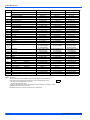
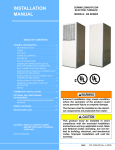
USER’S INFORMATION,
MAINTENANCE AND
SERVICE MANUAL
DOWNFLOW/UPFLOW
ELECTRIC FURNACE
ISO 9001
Certified Quality
Management System
MODELS: EB SERIES
TABLE OF CONTENTS
CONTACT INFORMATION FOR USA . . . . . . . . . . . . . . . . . . . . . . . 1
LUBRICATION . . . . . . . . . . . . . . . . . . . . . . . . . . . . . . . . . . . . . . . . .2
CONTACT INFORMATION FOR CANADA . . . . . . . . . . . . . . . . . . . 1
BLOWER ASSEMBLY . . . . . . . . . . . . . . . . . . . . . . . . . . . . . . . . . . . .2
SAFETY . . . . . . . . . . . . . . . . . . . . . . . . . . . . . . . . . . . . . . . . . . . . . . . . 1
AIR FILTER . . . . . . . . . . . . . . . . . . . . . . . . . . . . . . . . . . . . . . . . . . . .3
TO OPERATE FURNACE . . . . . . . . . . . . . . . . . . . . . . . . . . . . . . . . . . 2
RETURN AIR . . . . . . . . . . . . . . . . . . . . . . . . . . . . . . . . . . . . . . . . . . .3
TO SHUT FURNACE OFF . . . . . . . . . . . . . . . . . . . . . . . . . . . . . . . . 2
WHILE YOU’RE AWAY . . . . . . . . . . . . . . . . . . . . . . . . . . . . . . . . . . .3
SEQUENCE OF OPERATION . . . . . . . . . . . . . . . . . . . . . . . . . . . . . . . 2
AT THE BEGINNING OF EACH HEATING SEASON . . . . . . . . . . . .3
LIMIT CONTROLS . . . . . . . . . . . . . . . . . . . . . . . . . . . . . . . . . . . . . . 2
YOUR AUTHORIZED SERVICE TECHNICIAN . . . . . . . . . . . . . . . .3
BLOWER REMOVAL . . . . . . . . . . . . . . . . . . . . . . . . . . . . . . . . . . . . 2
OPTIONAL AIR CONDITIONING ACCESSORIES . . . . . . . . . . . . . .3
FURNACE OPERATION . . . . . . . . . . . . . . . . . . . . . . . . . . . . . . . . . . . 2
HIGH PERFORMANCE BLOWER ACCESSORY PACKAGE . . . . .3
CIRCUIT BREAKERS . . . . . . . . . . . . . . . . . . . . . . . . . . . . . . . . . . . . 2
REPAIR PARTS LIST . . . . . . . . . . . . . . . . . . . . . . . . . . . . . . . . . . . . .4
LIMITED WARRANTY . . . . . . . . . . . . . . . . . . . . . . . . . . . . . . . . . . . . .7
CONTACT INFORMATION FOR USA
•
Contact us by mail:
DISTRIBUTED BY:
Style Crest Inc.
Drawer A
Fremont, OH 43420
•
Manufacturer:
Johnson Controls,
Unitary Products
The manufacturer recommends that the user read all sections of this manual and keep the manual for future reference.
This furnace and its components, including the air conditioning coils
and blowers listed on the A/C accessory sticker were listed in combination as a system by Underwriters Laboratories.
Use of other components not tested in combination with this furnace
may make the equipment in violation of State Codes, may create a
hazard, and may ruin the equipment.
In addition, the National Manufactured Housing Construction and
Safety Standards Act and its Regulations require the use of components listed or certified by a nationally recognized testing laboratory
in all manufactured homes built and sold subject to that act.
CONTACT INFORMATION FOR CANADA
•
•
Go to website at www.york.com click on “contact”, then click on
“contact form” and follow the instructions.
Contact us by mail:
Johnson Controls Unitary Products
Consumer Relations
5005 York Drive
Norman, OK 73069
CAUTION indicates a potentially hazardous situation, which, if not
avoided may result in minor or moderate injury. It is also used to
alert against unsafe practices and hazards involving only property damage.
FOR YOUR SAFETY - Do not store or use gasoline or other
flammable vapors and liquids in the vicinity of this or any other
appliance.
For personal safety be sure to turn the electrical power OFF at
the household service box and at the furnace before attempting any service or maintenance operations. Homeowner
should never perform any maintenance which requires opening the furnace electrical panel.
Do not store or use gasoline or other flammable vapors and
liquids in the vicinity of this or any other appliance.
SECTION I: SAFETY
This is a safety alert symbol. When you see this symbol on
labels or in manuals, be alert to the potential for personal
injury.
To avoid the possibility of electrical shock do not open electrical box
panels.
Understand and pay particular attention to the signal words DANGER,
WARNING, or CAUTION.
DANGER indicates an imminently hazardous situation, which, if not
avoided, will result in death or serious injury.
WARNING indicates a potentially hazardous situation, which, if not
avoided, could result in death or serious injury.
Johnson Controls Unitary Products
570930-BUM-D-0613
570930-BUM-D-0613
SECTION II: TO OPERATE FURNACE
1. Be sure electrical power to furnace is turned on at the house-hold
service box.
FILTER (IN
DOWNFLOW
ONLY) *
2. Set wall thermostat to the desired temperature.
3. If furnace is equipped with Air Conditioning, the System Switch,
located at the wall thermostat, must be turned to HEAT in order for
the furnace to operate in the heating model.
CAVITY
FOR
COIL
If you have an air conditioner which does not use the furnace blower
for air distribution and operates completely independent of the furnace, the thermostat system must have an interlock to prevent the
furnace and air conditioner from operating at the same time. Such
operation could cause equipment damage, energy waste and overheating of the home.
THERMOSTAT
WIRES
CIRCUIT
BREAKERS
ELECTRIC
PANEL
The interlock system usually contains a heat-cool switch which must be
turned to either HEAT or COOL to activate either heating or cooling
operation.
If an interlock system has not been provided, the electrical supply to the
furnace must be turned OFF at the household service box, when the air
conditioner is being used. When operating the furnace, the electrical
supply to the air conditioner must be turned OFF.
TO SHUT FURNACE OFF
1. Turn thermostat to its lowest setting.
NOTICE
Furnace will still operate if room temperature falls below thermostat
setting.
2. For complete shut-down, turn off electrical power at the household
service box.
SECTION III: SEQUENCE OF
OPERATION
When room thermostat calls for heat, 24-volt power is supplied to the
heating element switches. As soon as the first heating element switch
closes, the blower starts and power is supplied to the first heating element. Each additional element is staged on in successive intervals.
When the room thermostat is satisfied and no more heat is required, the
elements sequence off in the reverse order and the blower will then turn
off.
LIMIT CONTROLS
FIELD WIRING
PROTECTIVE
SHIELD
UL
R
* Filter in the front panel when louvered doors
are used. Filter located in base for upflow units.
FIGURE 1: Component Locations
SECTION IV: FURNACE OPERATION
CIRCUIT BREAKERS
Your electric furnace is equipped with a unique safety feature - circuit
breakers. These circuit breakers are located behind the door of the furnace, near the bottom of the furnace. See Figure 1. If a component
should fail inside the furnace, the circuit breakers will prevent damage
that can be caused by an electrical short. If the breakers ever trip, they
can be reset by first turning off the power to the furnace at the home's
circuit breaker panel. See Warning below. Then remove the furnace
door and reset the circuit breaker in the furnace. Re-install the furnace
door and turn the power back on at the home's breaker panel. If for
some reason these circuit breakers should trip again, a service technician should be contacted as a problem exists inside the furnace. A list
of authorized service centers is provided with every furnace and will
assist you in obtaining service for your furnace.
You must first de-energize the furnace at the main household power
supply and lock it.
Each element has an automatic limit switch which is wired into the circuit and shuts off power to that element if the heat at that point exceeds
the allowable maximum heat.
BLOWER REMOVAL
NOTICE
Only authorized service technicians should remove the blower.
To remove blower from furnace, turn off power at household service
box, turn furnace circuit breakers OFF. Disconnect wiring to blower, and
remove five (5) screws holding blower in furnace and slide blower out
from front of the furnace. See Figure 1.
LUBRICATION
The blower motor bearings are factory sealed. Additional lubrication is
not required.
BLOWER ASSEMBLY
Every electric furnace comes equipped with a blower capable of operating a heat pump or air conditioner. With the addition of the proper heat
pump, you can enjoy comfort and savings all year long. An air conditioner will also work with your furnace and will provide cool summer
days, at a very low operating cost.
Re-install blower in reverse order when assembling back into furnace.
2
Johnson Controls Unitary Products
570930-BUM-D-0613
AIR FILTER
YOUR AUTHORIZED SERVICE TECHNICIAN
The filter supplied with the furnace is a throw-away type. Filters need to
be cleaned frequently. Shake out all loose dirt, and use vacuum cleaner
to clean additionally. This method of cleaning will prolong life of filters.
DO change filters often since clean filters not only provide added comfort, better and cleaner environment, but increase the efficiency of the
furnace as well.
Your furnace's best friend is your service technician. If the unit gives
any indication of improper operation, call your authorized service technician. If the service technician is allowed to perform the normal routine
care of your furnace, many times he can detect potential difficulties and
make corrections before trouble develops. Preventive maintenance of
this type will allow you to operate this unit with a minimum of concern
and pay for itself in added years of comfort.
FILTER LOCATION: The furnace's front panel must be removed to gain
access to the filter of the downflow furnace. (See Figure 1.) However,
the filter for the upflow furnace* is located behind the return air grill,
adjacent to the furnace closet or any other location in the return air.
RETURN AIR
Return air must be provided back to the circulating blower in order to
provide air distribution. DO NOT OBSTRUCT ANY RETURN AIR
GRILLE. To do so will cause the furnace heating elements to cycle off
and on repeatedly.
WHILE YOU’RE AWAY
The power supply to your furnace is equipped with either a fused or
breaker type disconnect. In case of an overload, this will interrupt the
operation of your furnace until it is reset or fuse replaced. For this reason it is never practical to assume that the furnace will operate unattended for long periods of time, especially if there is a possibility of
damage to your property because of freezing. So, if you plan to be
away, arrange for someone to check your home every day or so.
AT THE BEGINNING OF EACH HEATING SEASON
NOTICE
Be sure electrical supply to furnace is turned off at the household
service box and furnace circuit breakers before cleaning.
1. Replace filters as discussed previously. Clean dust and lint from in
and around the furnace. Clean dust and lint from blower and blower
compartment.
2. If furnace fails to operate properly:
a.
Be sure electrical power is being supplied to furnace. Check
main household power supply.
b.
If, after following this procedure, the furnace still fails to operate, shut off furnace and contact your service technician.
Johnson Controls Unitary Products
OPTIONAL AIR CONDITIONING ACCESSORIES
This furnace is equipped with a blower and control system to add-on air
conditioning and heat pumps to specified sizes. Insulation and coil shelf
kit (3500-8941 for downflow or 3500-8961/A for upflow) must be
installed when adding on such remote air conditioning systems.
NOTICE
If the controls are located at the top of the unit, the furnace is an
upflow furnace and the airflow is forced up through the furnace and
into the airways.
Failure to install this insulation and coil shelf kit could result in damage to equipment and/or personal injury. Liability and warranty from
the manufacturer could also be void.
HIGH PERFORMANCE BLOWER ACCESSORY
PACKAGE
All EB furnaces are equipped with a blower and control system to addon air conditioning and heat pumps to specified sizes. If the requirement is to achieve more air flow or cooling than specified, then the
blower inside the furnace has to be replaced with an accessory blower
package 3500-7901*. This accessory blower package would deliver air
conditioning up to 5-tons, and heat pump up to 4-tons. Accessory package (3500-7901*) includes blower, insulation, coil shelf, trap, clamps,
etc. Please refer to the installation instructions packed with the accessory package for more information.
All areas around the line sets, drain hoses and other openings in the
furnace should be sealed airtight. Use some moldable compound or
caulking to seal the area. Failure to do so may result in loss of performance and premature compressor failure.
3
570930-BUM-D-0613
SECTION V: REPAIR PARTS LIST
11
13
29 28
1
3
4
9
10
14
17
15
21
20
22
24
12
25
16
17
23
26
5
6
27
7
4
19
18
Johnson Controls Unitary Products
570930-BUM-D-0613
ITEM
DESCRIPTION
Front Panel (Insulated)
Filter (20 x 20 x 1) (Front Return Panel)
Front Panel (Louvered, 4-Ton) (Insul)
2* (Opt)
Front Panel (Front Return, 5-Ton)
3
Filter (16 x 20 x 1)
4
Support Angle (Door)
5
Cover, Electric Box
6
Cover (Service Entrance)
Sub-base (Optional)
7
Sub-base (M10) (Optional)
8
9
Blower Housing
10
Blower Motor
11
Capacitor (7.5MFD/370V)
12
Relay, Fan
13
Motor Mount Assembly Kit (1PC)
14
Blower Wheel
15
Sequencer
16
Transformer (240/24V-40A)
Heater Element Assembly w/Limit and Jumper
17
Wire
1
18
19
20
21
22
23
24
25
26
27
28
29
30
31*
NOTE:
Limit Switch
Fusible Link
Bracket (Circuit Breaker)
Circuit Breaker (1 Req’d)
Circuit Breaker (2 Req’d)
Buss Bar
(See Note 2)
Ground Lug (Large)
Ground Lug (Small)
Drain Tube
(See Note 1)
Condensate Trap
(See Note 1)
Coil Shelf
(See Note 1)
Coil Shelf Panel
(See Note 1)
Ferrule (3 Req’d)
Grommet (3 Req’d)
Fuse
Wiring diagram
EB10D
EB12D
EB15D
3501-9111
S1-1214-2521
3501-9211
3500-1591
S1-1214-2511
S1-3500-1861
S1-3500-2351/A
S1-3500-1271
S1-3500-1071/B
3500-5221
3501-9111
S1-1214-2521
3501-9211
3500-1591
S1-1214-2511
S1-3500-1861
S1-3500-2361/A
S1-3500-1271
S1-3500-1071/B
3500-5221
3501-9111
S1-1214-2521
3501-9211
3500-1591
S1-1214-2511
S1-3500-1861
S1-3500-2361/A
S1-3500-1271
S1-3500-1071/B
3500-5221
S1-37323744001
S1-02427651000
S1-02420045700
S1-3110-3301
S1-37319831002
S1-02632627700
S1-3110-3571
S1-3300-3861
(9.6Kw)
S1-02541236000
S1-37323744001
S1-02427651000
S1-02420045700
S1-3110-3301
S1-37319831002
S1-02632627700
S1-3110-3571
S1-3300-3861
(11.2Kw)
S1-02541238000
S1-02541249000 (Open
200, Close 60)
S1-02435663000
3500-128
S1-3500-377P/A
--S1-3500-378P
1216-231
--S1-02922184001
S1-3240-3051
3500-174
3500-171
S1-02320541000
S1-02814740000
S1-02532746026
570551
S1-02541249000 (Open
200, Close 60)
S1-02435663000
3500-128
--S1-3500-377P/A
S1-3500-378P
1216-231
--S1-02922184001
S1-3240-3051
3500-174
3500-171
S1-02320541000
S1-02814740000
S1-02532746026
570539
S1-37323744001
S1-02427651000
S1-02420045700
S1-3110-3301
S1-37319831002
S1-02632627700
S1-3115-3571
S1-3300-3861
(4.8Kw) & (9.6Kw)
S1-02541237000
S1-02541236000
S1-02541249000 (Open
200, Close 60)
S1-02435663000
3500-128
--S1-3500-377P/A
S1-3500-378P
1216-231
S1-02521798000
S1-02922184001
S1-3240-3051
3500-174
3500-171
S1-02320541000
S1-02814740000
S1-02532746026
570540
<
*Not Shown
New replacement parts shown in bold face type at the first printing of parts list dated 4/10.
Major components and suggested stocking items are shown with shaded item number.
“<“Across from row indicates a change in that row.
--- Not applicable to specified model.
All parts with three digit suffix numbers are “Special Order” parts. These parts are subject to factory
availability and require extra time for delivery.
1 Not Standard with furnace, contained in accessory kit no. 3500-8941/B.
2 Standard on EB12*.
Johnson Controls Unitary Products
5
570930-BUM-D-0613
ITEM
DESCRIPTION
Front Panel (Louvered, 4-Ton) (Insul)
Filter (20 x 20 x 1) (Front Return Panel)
Front Panel (Insulated)
2* (Opt)
Front Panel (Front Return 5-Ton)
3
Filter (16 x 20 x 1)
4
Support Angle (Door)
5
Cover, Electric Box
6
Cover (Service Entrance)
Sub-base (Optional)
7
Sub-base (M10) (Optional)
8
9
Blower Housing
10
Blower Motor
11
Capacitor (7.5MFD/370V)
12
Relay, Fan
13
Motor Mount Assembly Kit (1PC)
14
Blower Wheel
15
Sequencer
16
Transformer (240/24V-40A)
Heater Element Assembly w/Limit and Jumper
17
Wire
1
Limit Switch
18
19
20
21
22
Fusible Link
Bracket (Circuit Breaker)
Circuit Breaker (2 Req’d) (See Note 2)
Buss Bar
Ground Lug (Large)
Ground Lug (Small)
Drain Tube
(See Note 1)
Condensate Trap
(See Note 1)
Coil Shelf
(See Note 1)
Coil Shelf Panel
(See Note 1)
Ferrule (3 Req’d)
Grommet (3 Req’d)
Fuse
Wiring diagram
23
24
25
26
27
28
29
30
31*
EB17D
EB20D
EB23D
3501-9211
S1-1214-2521
3501-9111
3500-1591
S1-1214-2511
S1-3500-1861
S1-3500-2361/A
S1-3500-1271
S1-3500-1071/B
3500-5221
3501-9211
S1-1214-2521
3501-9111
3500-1591
S1-1214-2511
S1-3500-1861
S1-3500-2361/A
S1-3500-1271
S1-3500-1071/B
3500-5221
3501-9211
S1-1214-2521
3501-9111
3500-1591
S1-1214-2511
S1-3500-1861
S1-3500-2361/A
S1-3500-1271
S1-3500-1071/B
3500-5221
S1-37323744001
S1-02427651000
S1-02420045700
S1-3110-3301
S1-37319831002
S1-02632627700
S1-3115-3571
S1-3300-3861
(5.6Kw) & (10.4Kw)
S1-02541239000
S1-02541240000
S1-02541249000 (Open
200, Close 60)
S1-02435663000
3500-128
S1-3500-377P/A
S1-3500-378P
1216-231
S1-02521798000
S1-02922184001
S1-3240-3051
3500-174
3500-171
S1-02320541000
S1-02814740000
S1-02532746026
570571
S1-37323744001
S1-02427651000
S1-02420045700
S1-3110-3301
S1-37319831002
S1-02632627700
S1-3120A3571
S1-3300-3861
2 Ea. (9.6Kw)
S1-02541236000
S1-37323744001
S1-02427651000
S1-02420045700
S1-3110-3301
S1-37319831002
S1-02632627700
S1-3120A3571
S1-3300-3861
(10.4Kw) & (11.2Kw)
S1-02541240000
S1-02541238000
S1-02541249000 (Open
200, Close 60)
S1-02435663000
3500-128
S1-3500-377P/A
S1-3500-378P
1216-231
S1-02521798000
S1-02922184001
S1-3240-3051
3500-174
3500-171
S1-02320541000
S1-02814740000
S1-02532746026
570573
S1-02541249000 (Open
200, Close 60)
S1-02435663000
3500-128
S1-3500-377P/A
S1-3500-378P
1216-231
S1-02521798000
S1-02922184001
S1-3240-3051
3500-174
3500-171
S1-02320541000
S1-02814740000
S1-02532746026
570572
<
NOTE:
*Not Shown
New replacement parts shown in bold face type at the first printing of parts list dated 4/10.
Major components and suggested stocking items are shown with shaded item number.
“<“Across from row indicates a change in that row.
--- Not applicable to specified model.
All parts with three digit suffix numbers are “Special Order” parts. These parts are subject to factory
availability and require extra time for delivery.
1 Not Standard with furnace, contained in accessory kit no. 3500-8941/B
6
Johnson Controls Unitary Products
570930-BUM-D-0613
Limited Warranty
Manufactured Housing Furnaces
WARRANTY TERMS: Johnson Controls Unitary Products (hereinafter “Company”) warrants this product to be free from defects in factory workmanship and material under normal use and service and will, at its option, repair or replace any parts, without charge, subject to the exclusions below,
that prove to have such defects according to the terms outlined in this warranty. Company reserves the right, at its sole discretion, to provide a
replacement unit in the place of repair parts, in which case the warranty period for the replacement unit is limited to the remainder of the original warranty period. Alternatively, Company may, at its option, extend a replacement allowance to be applied toward the purchase of a new unit marketed by
Company. The exact amount of the allowance will be determined at the discretion of Company, based upon current market conditions, but in no case
shall this allowance exceed thirty (30) percent of the original consumer purchase price of the unit excluding such items as ductwork, wiring, piping,
and installation costs. The warranty period for repair or replacement parts or unit provided hereunder shall not extend beyond the warranty period
stated below. Company shall have no responsibility hereunder for installation, shipping, handling, or other charges except as specifically provided
herein.
This warranty covers only the equipment described by the Product Model Number and Unit Serial Number on the equipment or listed on the Warranty Registration Card, and applies only to products installed in the United States, Canada, or Puerto Rico. Tampering, altering, defacing, or removing the product serial number will serve to void this warranty. This warranty extends only to the original consumer purchaser and is nontransferable.
For this warranty to apply, the product must be installed according to Company recommendations and specifications, and in accordance with all
local, state, and national codes; and the product or residence must not be removed from its place of original installation. This warranty does not apply
to any unit sold over the Internet, by telephone or other electronic means unless the dealer that buys or sells a unit over the Internet, by telephone or
other electronic means also installs the unit. In the absence of a recorded Warranty Registration Card, the warranty period will begin upon product
shipment from Company. If you are unaware of the date the warranty became effective, contact Company at (877) 874-7378 or visit www.upgproductregistration.com.
ADDITIONAL CONDITIONS FOR HEAT EXCHANGER WARRANTY: This warranty shall cover the heat exchanger (primary and/or secondary, if
applicable) only if:
1. The product has not been operated with an input rate in excess of the rating plate attached to the product.
2. The product has not been allowed to operate without the use of the proper automatic limit control on the maximum warm air temperature
and/or without adequate circulation.
3. The product is installed so that the combustion air is not contaminated by compounds of chlorine, fluorine, or other damaging chemicals
(or vapors).
4. The product is installed such that the heat exchangers are not exposed to return air temperatures below stated ratings.
FOR PRODUCT REGISTRATION: For your benefit and protection, register your product with Company promptly after installation. This will initiate
the warranty period and allow us to contact you, should it become necessary. You can register your product online at www.upgproductregistration.com or by returning the Warranty Registration Card on the back page of this packet.
Product Model Number: ____________________________________
Installation Date: __________________________________________
Unit Serial Number: _______________________________________
Installing Dealer: __________________________________________
FOR WARRANTY SERVICE OR REPAIR: Consult the Authorized Service Center List packed with the unit installed in the manufactured home or
contact your installing or servicing dealer. The Authorized Service Center List is also available online at http://www.stylecrestinc.com/manufacturedhousing-products/hvac-service-documents/
Or, look in the Yellow Pages of the telephone book under Mobile Homes or Manufactured Housing Repair and Service for the name and telephone
number of the nearest authorized manufactured housing service center. If local authorized service cannot be obtained, or you are unable to contact
your installing dealer, contact the authorized distributor in your area. If you are unable to contact an authorized servicer, please contact StyleCrest
Inc., at 1-800-231-4822. If there is no distributor in your area, and you cannot obtain proper service under the terms of the warranty, please write:
Johnson Controls Unitary Products, Consumer Relations, 5005 York Drive, Norman, OK 73069.
WARRANTY PERIOD: The warranty period in years, depending on the part, is as shown in the chart below.
Furnace Model
EB
Parts Coverage
Labor and Trip Coverage*
2 years
1 year
NOTES:
*The warranty period for any replacement part provided here under shall not extend beyond the warranty period stated above.
The warranty period will begin on the purchase date of the residence when the product is installed as original equipment, or the installation date when installed in a residence previously purchased by the consumer.
MAINTENANCE: Company strongly recommends regular periodic preventive maintenance on this equipment. The person most familiar with the
equipment in your HVAC system is a Participating Dealer. The Participating Dealer can ensure that your maintenance program meets the “Company
Warranty” conditions, maximize the equipment efficiency, and service your unit within the mandated guidelines with regard to unlawful discharge of
refrigerants into the atmosphere.
Johnson Controls Unitary Products
7
EXCLUSIONS: This warranty does not cover any:
1. Shipping, labor, or material charges or damages resulting from transportation, installation, or servicing.
2. Damage or repairs required as a consequence of mishandling, faulty installation, misapplication, abuse, improper servicing, unauthorized alteration, or improper operation.
3. Damages or failure to start resulting from improper voltage conditions, blown fuses, open circuit breakers, or other inadequacy or interruption of
electrical service or fuel supply.
4. Fuses, either internal or external to the product.
5. Labor or other costs incurred for diagnosing, repairing, removing, installing, shipping, servicing, or handling of either defective parts or replacement parts.
6. Products removed from their original location for reinstallation purposes.
7. Damages resulting from accident, abuse, fire, flood, alteration, or acts of God.
8. Damages resulting from use of the product in a corrosive atmosphere.
9. Normal maintenance, or damages resulting from failure to perform normal maintenance, as outlined in the installation and servicing instructions
or owner's manual.
10. Cleaning or replacement of filters, nozzles, or orifices.
11. Damages resulting from operation with inadequate supply of air or water; Damages resulting from failure to properly and regularly clean air and/
or water side of condenser and evaporator.
12. Damages resulting from: (I) freezing of condenser water or condensate; (II) inadequate or interrupted water supply; (III) use of corrosive water;
(IV) fouling or restriction of the water circuit by foreign material or like causes.
13. Damages caused by improper parts, components or accessories not suitable for use in or with the unit. For a list of parts that are known to be
compatible please reference the equipment renewal parts list, contact a Participating Dealer for assistance, or call 1-877-874-7378.
14. Electricity or fuel costs, or increases in fuel or electric costs, for any reason including additional or unusual use of supplemental electric heat.
This warranty is in lieu of all other express warranties. All implied warranties, including the implied warranty of merchantability and fitness for a particular purpose are limited in duration to the actual warranty period applicable to the part. Some states do not allow the disclaimer of implied warranties,
so the above disclaimer may not apply to you. In addition, some states do not allow limitations on how long an implied warranty lasts, so the above
limitation may not apply to you. In no event, whether as a result of breach of warranty or contract, tort (including negligence), strict liability, or otherwise, shall Company be liable for special, incidental, or consequential damages or expenses, including but not limited to loss of use of the equipment
or associated equipment, lost revenues or profits, cost of substitute equipment, or cost of fuel or electricity.
The above limitations shall inure to the benefit of Company's suppliers and subcontractors. The above limitation on consequential damages shall not
apply to injuries to persons in the case of consumer goods. Company does not assume, or authorize any other person to assume for Company, any
other liability for the sale of this product. Some states do not allow the exclusion or limitation of incidental or consequential damages, so the above
limitation may not apply to you. This warranty gives you specific legal rights. You may also have other rights which vary from state to state.
Subject to change without notice. Published in U.S.A.
Copyright © 2013 by Johnson Controls, Inc. All rights reserved.
York International Corp.
3110 N. Mead
Wichita, KS 67219
570930-BUM-D-0613
Supersedes: 570930-BUM-C-0112