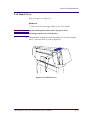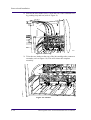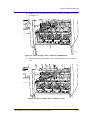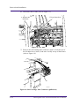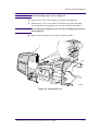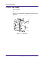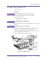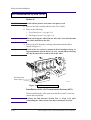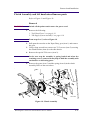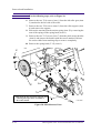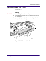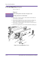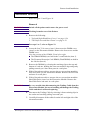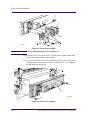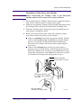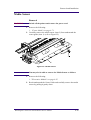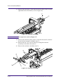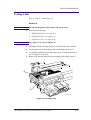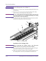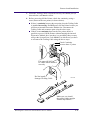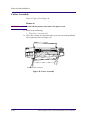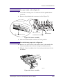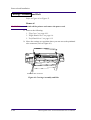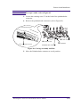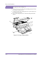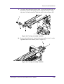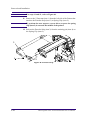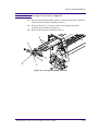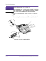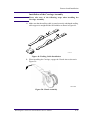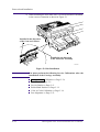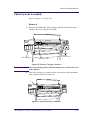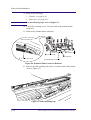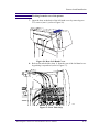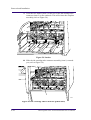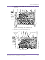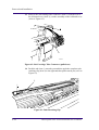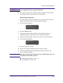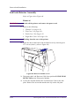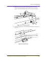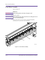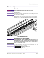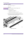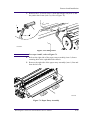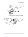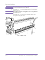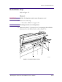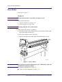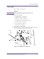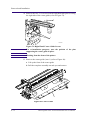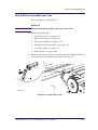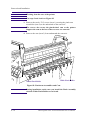
1
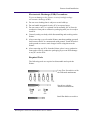
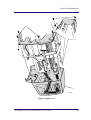
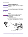
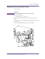
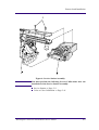
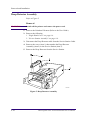
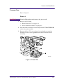
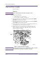
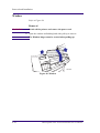
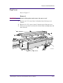
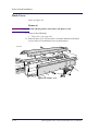
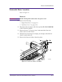
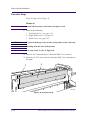
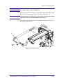
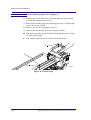
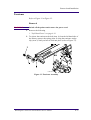
Removal and Installation
8
8
Right Hand Cover 8-4
Front Panel Assembly 8-6
Right Hand Trim and Window Switch 8-7
Service Station Assembly 8-8
Drop Detector Assembly 8-10
Vacuum Fan 8-11
Paper-axis Motor Assembly 8-12
Left Hand Cover 8-13
Left Hand Trim Assembly 8-18
Ink Supply Station Assembly (ISS) 8-19
Air Pressurization System (APS) 8-20
Clutch Assembly and left hand miscellaneous parts 8-21
Tail Deflectors and Rear Platen 8-23
Left and Right Rear Covers 8-24
Electronics Module 8-25
Media Sensor 8-29
Window 8-30
Top Cover 8-31
Back Cover 8-32
Scan-axis Motor Assembly 8-33
Encoder Strip 8-34
Tensioner 8-37
Trailing Cable 8-39
Cutter Assembly 8-42
Carriage Assembly and Belt 8-44
Tubes System Assembly 8-53
Ink Leak Detector Assembly 8-60
Front Platen Assembly 8-62
Platen Assembly 8-63
Paper Entry Assembly 8-64
Roller Guide 8-66
Media Holder Strip 8-69
Drive Roller 8-70
Center Guide 8-71
Pinch-Wheel Assembly and Cam 8-73
HP DesignJets 1050C and 1055CM Printers Service Manual
8-1
Removal and Installation
Introduction
This chapter is a step by step guide to the removal and installation
of the key components in the printer. You may find it useful to tick off
the steps as they are performed. Use the illustration at each
procedure to identify the parts referred to in the text.
The procedures appear in order of removal. So the whole machine
can be stripped down by starting at the beginning of this chapter
and working through the subsequent procedures.
NOTE
Before using this chapter to remove and install a new component,
always make sure that you have performed the relevant service
test from Chapter 4. If the test passes you will not need to replace
the component.
Safety Precautions
(Safety symbols - Immediately after the table of contents.)
Review WARNING and CAUTION symbols and instructions before
you service the printer. Follow these warnings and cautions for your
protection and to avoid damaging the printer.
WARNING
Serious shock hazard leading to death or injury may result if you
do not take the following precautions:
Ensure that the ac power outlet (mains) has a protective earth
(ground) terminal.
Switch the plotter off, and disconnect it from the power source
prior to performing any maintenance.
Prevent water or other liquids from running onto electrical
components or circuits, or through openings in the module.
8-2
HP DesignJets 1050C and 1055CM Printers Service Manual
Removal and Installation
Electrostatic Discharge (ESD) Precautions
To prevent damage to the Printer circuits from high-voltage
electrostatic discharge (ESD):
1. Do not wear clothing that is subject to static build-up.
2. Do not handle integrated circuits (ICs) in carpeted areas.
3. Do not remove an IC or a printed circuit assembly (PCA) from its
conductive foam pad or conductive packaging until you are ready to
install it.
4. Ground (earth) your body while disassembling and working on the
Printer.
5. After removing a cover from the Printer, attach an earthing (ground)
lead between the PCA common and earth ground. Touch all tools to
earth ground to remove static charges before using them on the
Printer.
6. After removing any PCA from the Printer, place it on a conductive
foam pad or into its conductive packaging to prevent ESD damage
to any ICs on the PCA.
Required Tools
The following tools are required to disassemble and repair the
Printer.
Long Torx Screwdriver with
the indicated attachments
Nut driver with the
indicated attachments
Small flat-blade screwdriver
HP DesignJets 1050C and 1055CM Printers Service Manual
8-3
Removal and Installation
Right Hand Cover
Refer to Figure 1
Removal
1. Remove the Printhead Cleaners (Refer to the User Guide).
NOTE
Make sure that the Service Station Carriage is pushed to the
back before trying to remove the Right Cover.
WARNING
Switch off the printer and remove the power cable.
1. Remove the following:
1. "Electronics Module Left Rear Cover" see page 8-24.
NOTE
Make sure you take care when removing the ferrite which is
attached to the sideplate with a cable tie.
2. Disconnect the front panel cable from position P16 FRONT
PANEL on the electronics module.
3. Disconnect the aerosol fan cable from position P7 AEROSOL FAN
on the electronics module.
4. Remove two T-15 screws (item 1) from the right hand trim (item 2).
NOTE
Be careful not to drop the cover (item 3) once the securing
fasteners have been removed. Support the cover throughout the
next step.
5. Remove two T-15 screws (item 4) from the rear of the right hand
cover which are securing the cover to the right hand side chassis.
6. Remove the right hand cover (item 3) by making sure you:
a carefully pull the front panel cable and the aerosol fan cable from
a hole in the right hand side chassis.
b disconnect the service station door sensor cable, which hangs
down from the service station cable.
8-4
HP DesignJets 1050C and 1055CM Printers Service Manual
Removal and Installation
4
1
2
3
C607407
Figure 1: Right Cover
HP DesignJets 1050C and 1055CM Printers Service Manual
8-5
Removal and Installation
Installation of the Right Hand Cover
NOTE
Ensure the front panel cable and the aerosol fan cables are
secured inside the right hand cover with cable clamps and
retaining clips.
NOTE
At the rear of the right hand side chassis is a hole for the cables
to go through. If the cables are not through this hole when the
cover is in place on the printer the cover cannot be properly
installed.
Front Panel Assembly
Removal
1. Remove the Printhead Cleaners (Refer to the User Guide).
WARNING
Switch off the printer and remove the power cable.
1. Remove the following:
1. "Right Hand Cover" see page 8-4.
2. The Front Panel Assembly and the Front-Panel Assembly Cable can
be removed by releasing them from the retaining clips (item 1) and
cable clamps (item 2) inside the Right Hand Cover (item 3) (Refer
to Figure 2).
3
1
2
C607436
Figure 2: Front Panel
8-6
HP DesignJets 1050C and 1055CM Printers Service Manual
Removal and Installation
Right Hand Trim and Window Switch
Refer to Figure 3.
Removal
WARNING
Switch off the printer and remove the power cable.
1. Remove the following:
1. "Right Hand Cover" see page 8-4.
2. Disconnect the Window Switch cable from the Service Station
cable.
3. Remove 2 screws (Item 1) that attach the Right Hand Trim (Item 2)
to the Printer.
4. Remove the Right Hand Trim (Item 2) from the Printer.
1
2
Figure 3: Right Hand Trim
HP DesignJets 1050C and 1055CM Printers Service Manual
8-7
Removal and Installation
Service Station Assembly
Refer to Figure 4.
Removal
WARNING
Switch off the printer and remove the power cord.
1. Remove the Printhead Cleaners (Refer to the User Guide).
2. Remove the following
1. "Right Hand Cover" see page 8-4.
3. Disconnect the service station cable from the electronics module out
of position SERVICE STATION.
4. Disconnect the window switch and right door switch cables from
the service station cable.
5. Unclip the Scan-Axis Motor cable from the Service Station.
6. Manually slide the carriage assembly to the middle of the printer.
NOTE
Be careful not to drop the service station (item 2) once the
securing fasteners have been removed. Support the service
station throughout the following steps.
7. Between the carriage assembly slider rods there are two holes.
These holes give you access to two T-15 screws (item 3). Remove
the two T-15 screws.
8. Loosen the T-15 screw (item 1) securing the service station to the
side of the printer. This screw is long and does NOT need to be fully
loosened.
NOTE
When removing the Service Station, make sure that you release
the Paper-axis Motor cable from the clip that is located on the
Service Station.
9. Lift the service station (item 2) off the loosened screw (item 1) and
standing in front of the printer, slide the assembly towards you.
8-8
HP DesignJets 1050C and 1055CM Printers Service Manual
Removal and Installation
3
1
2
Figure 4: Service Station Assembly
NOTE
You must perform the following Service Calibrations after the
installation of the Service Station Assembly.
n
n
Service Station ⇒ Page 5-11.
Color to Color Calibration ⇒ Page 5-16.
HP DesignJets 1050C and 1055CM Printers Service Manual
8-9
Removal and Installation
Drop Detector Assembly
Refer to Figure 5.
Removal
WARNING
Switch off the printer and remove the power cord.
1. Remove the Printhead Cleaners (Refer to the User Guide).
2. Remove the following
1. "Right Hand Cover" see page 8-4.
2. "Service Station Assembly" see page 8-8.
3. Disconnect the Drop Detector cable from the Service Station Cable.
4. Remove the screw (item 1) that attaches the Drop Detector
Assembly (item 2) to the Service Station (item 3).
5. Remove the Drop Detector from the Service Station.
1
2
3
C607436
Figure 5: Drop Detector Assembly
8-10
HP DesignJets 1050C and 1055CM Printers Service Manual
Removal and Installation
Vacuum Fan
Refer to Figure 6.
Removal
WARNING
Switch off the printer and remove the power cord.
1. Remove the following:
1. "Right Hand Cover" see page 8-4.
2. "Service Station Assembly" see page 8-8.
2. Disconnect the vacuum fan cable from position P7 VACUUM FAN
on the electronics module.
3. Remove the four T-15 screws (item 1) securing the vacuum fan
assembly (item 2) to the right hand side chassis and remove the
assembly.
1
1
2
C607421
Figure 6: Vacuum Fan
HP DesignJets 1050C and 1055CM Printers Service Manual
8-11
Removal and Installation
Paper-axis Motor Assembly
Refer to Figure 7.
Removal
WARNING
Switch off the printer and remove the power cord.
1. Remove the following:
1. "Right Hand Cover" see page 8-4.
2. "Service Station Assembly" see page 8-8.
2. Disconnect the Paper-axis Motor cable from position P3 PAPER
MOTOR on the electronics module.
3. Disconnect the Paper-axis encoder cable from position P1 PAPER
ENCODER on the electronics module.
4. Remove the two T-10 screws (item 1) securing the gear (item 2) to
the right side of the roller and remove the gear.
5. Remove the four T-20 screws (item 3) securing the Paper-axis
Motor Assembly (item 4) to the right hand chassis. Remove the
Paper-axis Motor Assembly.
3
4
3
1
2
C607421
Figure 7: Paper-axis Motor Assembly
NOTE
8-12
You must perform the Accuracy Calibration (⇒ Page 5-6) after
the installation of the Paper-Axis Motor Assembly.
HP DesignJets 1050C and 1055CM Printers Service Manual
Removal and Installation
Left Hand Cover
Refer to Figure 8 to Figure 15.
Removal
1. Remove the Ink Cartridges (Refer to the User Guide).
WARNING
Switch off the printer and remove the power cord.
NOTE
Working from the rear of the printer.
1. Open the door at the back of the left hand cover by removing the
two T-15 screws (item 1) (refer to Figure 8).
1
Figure 8: Left Hand Cover
HP DesignJets 1050C and 1055CM Printers Service Manual
8-13
Removal and Installation
2. Release the tube holder (item 1) from the rear of the left hand cover
by pushing it up and out (refer to Figure 9).
1
2082a
Figure 9: Tube Grip
3. Twist the two latches at the rear of the ink cartridge tube connector
outwards (refer to Figure 10). This will release the complete
assembly.
1
2
Figure 10: Latches
8-14
HP DesignJets 1050C and 1055CM Printers Service Manual
Removal and Installation
4. Slide the ink cartridge tube connector assembly towards you (refer
to Figure 11).
1
2082c
Figure 11: Ink Cartridge Tube Connector (pulled back)
5. Disconnect the ink cartridge tube connector cable (refer to Figure
12).
1
Figure 12: Ink Cartridge Tube Connector Cable
HP DesignJets 1050C and 1055CM Printers Service Manual
8-15
Removal and Installation
6. Disconnect the air tube (refer to Figure 13).
1. Press down here
2. Release the
tube here
Figure 13: Air Tube
7. Remove the ink cartridge tube connector (item 1) from the rear of
the left hand cover (item 2) and store it safely on top of the Printer
(refer to Figure 14).
2
1
C607431
Figure 14: Ink Cartridge Tube Connector (pulled out)
8-16
HP DesignJets 1050C and 1055CM Printers Service Manual
Removal and Installation
NOTE
In the following steps, refer to Figure 15.
8. Remove two T-15 screws (item 1) from the left hand trim.
9. Remove two T-15 screws (item 2) from the rear of the left hand
cover which are securing the cover to the left hand side chassis.
NOTE
Be careful not to drop the cover once the securing fasteners have
been removed.
10. Remove the left hand cover (item 3) from the printer.
2
3
1
4
C607406
Figure 15: Left Hand Cover
HP DesignJets 1050C and 1055CM Printers Service Manual
8-17
Removal and Installation
Left Hand Trim Assembly
Refer to Figure 16.
Removal
1. Remove 4 screws (Item 1) that attach the Left Hand Trim (Item 2) to
the Printer.
2. Remove the Left Hand Trim (Item 2) from the Printer.
2
1
C607406
Figure 16: Left Hand Trim
8-18
HP DesignJets 1050C and 1055CM Printers Service Manual
Removal and Installation
Ink Supply Station Assembly (ISS)
Refer to Figure 17.
Removal
WARNING
Switch off the printer and remove the power cord.
1. Remove the Ink Cartridges (Refer to the User Guide).
2. Remove the following:
1. "Left Hand Cover" see page 8-13.
2. "Left Rear Cover" see page 8-24.
NOTE
Working from the rear of the printer.
3. Disconnect all the cables from the right hand side of the electronics
module.
NOTE
Working from the front of the printer.
4. Unclip the latch and lift up the front of the assembly to release the
front support of the ISS from a hole in the side chassis.
5. Push the ISS away from you to release the back support of the ISS
from a second hole in the side chassis.
6. Move the ISS to the left to remove completely.
Figure 17: Ink Supply System
HP DesignJets 1050C and 1055CM Printers Service Manual
8-19
Removal and Installation
Air Pressurization System (APS)
Removal
WARNING
Switch off the printer and remove the power cord.
1. Remove the Ink Cartridges (Refer to the User Guide).
2. Remove the following:
1. "Left Hand Cover" see page 8-13.
2. "Ink Supply System" see page 8-19.
When removing the APS from the ISS, take care with the tube
and cables attached to the ISS.
NOTE
3. Release the APS from the retaining clips underneath the ISS as
shown in Figure 18.
NOTE
If ink in the air system is suspected (Ink Cartridge leakage or
depressurization System Error), be very careful when removing
the APS because there could be ink in the APS.
Release from
these clips
C607443
Figure 18: Air Pressurization System
Installation of the Air Pressurization System (APS)
When assembling the APS, make sure that the air tube is correctly
routed and not pinched.
NOTE
8-20
Perform the Ink Pressure System Test (⇒ Page 4-14) after
reinstalling the APS to make sure that it functions correctly.
HP DesignJets 1050C and 1055CM Printers Service Manual
Removal and Installation
Clutch Assembly and left hand miscellaneous parts
Refer to Figure 19 and Figure 20.
Removal
WARNING
Switch off the printer and remove the power cord.
1. Remove the following:
1. "Left Hand Cover" see page 8-13.
2. "Ink Supply System Assembly" see page 8-19.
From steps 2 to 5, refer to Figure 19.
NOTE
2. Pull apart the two tabs on the Paper Entry gear (item 1) and remove
the gear.
3. Using a long screwdriver remove two T-15 screws (item 5) securing
the clutch bracket (item 6) to the side chassis.
4. Remove the special T-20 screw (item 2).
In the next step the assembly is spring loaded and when the
retaining screw is removed it may help to hold the assembly with
one hand to avoid loosing parts.
NOTE
5. Remove the gears (item 3) and the spring (item 4) in the clutch
assembly. Refer to the note above.
.
5
6
4
1
2
5
3
C607420a
Figure 19: Clutch Assembly
HP DesignJets 1050C and 1055CM Printers Service Manual
8-21
Removal and Installation
For the following steps, refer to Figure 20.
NOTE
6. Remove the two T-10 screws (item 1) from the left roller gear (item
2) attached to the left side of the roller.
7. Remove the two T-20 screws (item 3) from the roller support (item
4) and remove the support.
8. Release the tension from the torsion spring (item 5) by removing the
arm of the spring off the spring hook (item 6).
9. Remove the two T-15 screws (item 7) from the pinch sensor bracket
(item 8) and remove the bracket with the sensor attached. Release
the sensor cable from retaining clips to remove completely.
10. Remove the spring hook (T-15) (item 6).
1*
3*
4*
1*
6
3*
5
2*
7
7
8
* These items do not need to be removed when 7
removing the Paper Entry Assembly or
the Center Guide
C607420b
Figure 20: Miscellaneous Parts
8-22
HP DesignJets 1050C and 1055CM Printers Service Manual
Removal and Installation
Tail Deflectors and Rear Platen
Refer to Figure 21.
Removal
WARNING
Switch off the printer and remove the power cord.
1. Remove the three Deflectors (item 1) by unclipping them from the
Rear Platen (Item 3).
2. Remove two T-10 screws (item 2) on the left and right of the Rear
Platen (item 3) and remove the platen.
2
3
1
2
C607401
Figure 21: Tail Deflectors and Rear Platen
HP DesignJets 1050C and 1055CM Printers Service Manual
8-23
Removal and Installation
Left and Right Rear Covers
Refer to Figure 22.
Removal
WARNING
Switch off the printer and remove the power cord.
NOTE
Working from the rear of the Printer.
1. Remove the T-10 Screw (Item 1) that attaches the left hand rear
cover (Item 2) to the Printer.
2. Release the left hand rear cover (Item 2) from the retaining clip
(item 3) that attaches the ferrite (item 4) to the rear cover.
3. Remove the T-10 Screw (Item 5) that attaches the right hand rear
cover (Item 6) to the Printer.
4. Release the right hand rear cover (Item 6) from the retaining clip.
6
5
3
2
4
1
Figure 22: Left and Right Rear Covers
8-24
HP DesignJets 1050C and 1055CM Printers Service Manual
Removal and Installation
Electronics Module
Refer to Figure 23 and Figure 24.
Removal
WARNING
Switch off the printer and remove the power cord.
NOTE
Working from the rear of the Printer.
1. Remove the following:
1. "Left and Right Hand Rear Covers" see page 8-24.
2. "Tail Deflectors and Rear Platen" see page 8-23.
NOTE
For steps 2 to 7, refer to Figure 23.
2. Locate the four T-10 screws (item 1) that secure the DIMM cover
(item 2) to the Electronics Module. Remove the four screws and the
DIMM cover.
Note the position of the DIMMs. From left to right:
n The DRAM DIMM(s) are held in the 1st and 2nd slot (item 3).
n The Firmware/Postscript Code DIMM (Flash DIMM) are held in
the 3rd slot (Item 4).
3. Remove the DIMMs by releasing the retaining clips at the top and
bottom of each one, holding the outer non-metallic edge and gently
pulling towards you. Store these parts in a safe place.
4. With a flat end screwdriver, unscrew the two screws that attach the
EIO card (item 5) to the Electronics Module. Remove the EIO card
and store in a safe place.
5. With a flat end screwdriver, unscrew the two screws that attach the
Hard Disk Drive (item 6) to the Electronics Module. Remove the
Hard Disk Drive and store in a safe place.
WARNING
Be very careful when disconnecting the Trailing Cable from the
Electronics Module. Incorrect handling will damage the Trailing
Cable and then it will need replacing.
6. Disconnect the Trailing Cable by releasing it from retaining clips in
the socket and carefully pulling it towards you.
7. Carefully disconnect all the cables from the left and right side of the
electronics module.
HP DesignJets 1050C and 1055CM Printers Service Manual
8-25
Removal and Installation
5
4
3
6
1
2
C607402
Figure 23: Electronics Module
For the following steps, refer to Figure 24.
NOTE
8. Remove two T-20 screws (item 1) which can be found at both ends
of the electronics module at the bottom.
9. Loosen (do not remove) the two remaining T-20 screws (item 2) and
carefully remove the whole electronics module (item 3) by sliding it
up and pulling towards you.
2
1
2
3
1
C607403
Figure 24: Electronics Module
8-26
HP DesignJets 1050C and 1055CM Printers Service Manual
Removal and Installation
Installation of the Electronics Module
WARNING
When reconnecting the Trailing Cable to the Electronics
Module, make sure you connect it correctly as follows:
1. Start reconnecting the Trailing Cable from left to right (the longest
strip will be connected to the 1st clip from the right).
2. Make sure you push the Trailing Cable in straight and not bent. Once
the Trailing Cable is inserted, you should hear an audible click.
3. When the Trailing Cable is inserted correctly, the shaded part (as
shown below) will not be visible.
4. Before powering ON the Printer, check the continuity (using a
tester) between the two points (as shown below).
n If there is continuity between the two points, then the Trailing
Cable is installed incorrectly. Do NOT power ON the Printer
because you will burn an internal Electronics Module fuse.
Disconnect the Trailing Cable and reconnect again using the
above steps.
n If there is no continuity between the two points, then it is
possible to power ON the Printer without burning the internal
Electronics Module fuse, but there is a possibility that you may
still get the System Error Code 0B0006, in which case you have
to reconnect the Trailing Cable using the above steps.
Check Continuity
between these 2 points
This part will NOT
be visible when installed
correctly
Do Not install a
damaged Trailing Cable
HP DesignJets 1050C and 1055CM Printers Service Manual
C607440
8-27
Removal and Installation
NOTE
You must perform the following Service Calibration and Utility
after the installation of the Electronics Module.
n
n
8-28
Set Asian PS Fonts (only in Asia) ⇒ Page 4-33.
Calibrations Backup ⇒ Page 5-19 & Pen Alignment ⇒ Page 5-22.
HP DesignJets 1050C and 1055CM Printers Service Manual
Removal and Installation
Media Sensor
Removal
WARNING
Switch off the printer and remove the power cord.
1. Remove the following:
1. "Center Guide" see page 8-71.
2. Carefully remove the media sensor (item 2) from underneath the
center guide (item 1) (refer to Figure 25).
2
1
Figure 25: Media Sensor
NOTE
You may also be able to remove the Media Sensor as follows:
1. Remove the following:
1. "Electronics Module" see page 8-25.
2. Reach underneath the Center Guide and carefully remove the media
sensor by pulling it gently down.
HP DesignJets 1050C and 1055CM Printers Service Manual
8-29
Removal and Installation
Window
Refer to Figure 26.
Removal
WARNING
Switch off the printer and remove the power cord.
1. Open the window and holding both sides pull up to remove.
NOTE
The Window hinges must be vertical when pulling up.
C607404
Figure 26: Window
8-30
HP DesignJets 1050C and 1055CM Printers Service Manual
Removal and Installation
Top Cover
Refer to Figure 27.
Removal
WARNING
Switch off the printer and remove the power cord.
1. Remove one T-15 screw Item 1) from the front of the top cover
(item 2).
2. Remove five T-15 screws (item 3) from the rear of the top cover.
3. The top cover (Item 2) can now be released from retaining clips and
then removed.
1
3
2
C607405
Figure 27: Top Cover
HP DesignJets 1050C and 1055CM Printers Service Manual
8-31
Removal and Installation
Back Cover
Refer to Figure 28.
Removal
WARNING
Switch off the printer and remove the power cord.
1. Remove the following:
1. "Top Cover" see page 8-31.
2. Remove three T-15 screws (item 1) from the bottom of the back
cover (item 2). Lift the back cover up and remove.
C607405
2
1
Figure 28: Back Cover
8-32
HP DesignJets 1050C and 1055CM Printers Service Manual
Removal and Installation
Scan-axis Motor Assembly
Refer to Figure 29.
Removal
WARNING
Switch off the printer and remove the power cord.
1. Remove the following:
1. "Right Hand Cover" see page 8-4.
2. "Left Rear Cover" see page 8-24.
2. Disconnect the scan motor cable from position P3 SCAN MOTOR
in the electronics module.
3. Remove the two T-15 screws (item 1) that attach the Scan-axis
motor (item 2) to the Chassis.
4. Hold the Scan-axis motor at an angle, just enough so that the belt
(item 3) can be taken off.
5. Remove the Scan-axis Motor from the printer.
1
1
3
2
C60718
Figure 29: Scan-axis Motor Assembly
HP DesignJets 1050C and 1055CM Printers Service Manual
8-33
Removal and Installation
Encoder Strip
Refer to Figure 30 to Figure 32.
Removal
WARNING
Switch off the printer and remove the power cord.
1. Remove the following
1. "Left Hand Cover" see page 8-13.
2. "Right Hand Cover" see page 8-4.
3. "Back Cover" see page 8-32.
CAUTION
To prevent damage to the encoder strip, hold it at the ends only.
NOTE
Working from the rear of the printer.
NOTE
For steps 2 and 3, refer to Figure 30.
2. Remove five 7mm nuts (item 1) from the EMC Cover (item 2).
3. Remove two T-15 screws (item 3) from the EMC Cover and remove
the plate.
1
2
3
3
C607409
Figure 30: Encoder Strip
8-34
HP DesignJets 1050C and 1055CM Printers Service Manual
Removal and Installation
For steps 4 and 5, refer to Figure 31.
NOTE
4. Remove the 5.5mm nut (item 1) from the left side of the Printer that
attaches the Encoder Strip (item 3) to Spring Clip (item 2).
To perform the next step use a screw driver to press the spring
clip (item 2) in towards the middle of the printer.
NOTE
5. Release the Encoder Strip (item 3) from the retaining pin (item 4) on
the Spring Clip (item 2).
3
4
1
2
C60710
Figure 31: Encoder Strip
HP DesignJets 1050C and 1055CM Printers Service Manual
8-35
Removal and Installation
For the following steps, refer to Figure 32.
NOTE
6. Remove the 5.5mm nut (item 1) from the right side of the printer
securing the encoder strip (item 2).
7. Remove the encoder strip from retaining pins (item 3) on the right
side of the Printer Chassis.
8. Remove the encoder strip spacer (item 4).
9. Release the encoder strip from the carriage assembly.
10. Release the encoder strip from all the retaining pins (item 5) along
the back of the printer.
11. The encoder strip can now be removed from the printer.
4
1
3
2
5
C607411
Figure 32: Encoder Strip
8-36
HP DesignJets 1050C and 1055CM Printers Service Manual
Removal and Installation
Tensioner
Refer to Figure 33 to Figure 35.
Removal
WARNING
Switch off the printer and remove the power cord.
1. Remove the following
1. "Left Hand Cover" see page 8-13.
2. To release the tension on the belt (item 1) from the left hand side of
the Printer, squeeze the spring (item 2) using the tensioner wedge
clip (item 3) until you hear it click into place (refer to Figure 33).
2
3
1
C607415
Figure 33: Tensioner Assembly
HP DesignJets 1050C and 1055CM Printers Service Manual
8-37
Removal and Installation
3. Remove the belt (item 1) from the belt motor pulley (item 2) on the
right hand side of the Printer (refer to Figure 34)
2
1
Figure 34: Tensioner Assembly
For steps 4 to 6, refer to Figure 35.
NOTE
4. Remove the tensioner pulley (item 1) from the belt (item 2) which is
located in the tensioner assembly (item 3).
5. Remove the two T-15 screws (item 4) securing the tensioner
assembly to the slider rods (item 5).
6. Remove the tensioner assembly (item 3).
5
4
3
2
1
4
Figure 35: Tensioner Assembly
8-38
HP DesignJets 1050C and 1055CM Printers Service Manual
Removal and Installation
Trailing Cable
Refer to Figure 36 and Figure 37.
Removal
WARNING
Switch off the printer and remove the power cord.
1. Remove the following:
1. "Right Hand Cover" see page 8-4.
2. "Left Hand Cover" see page 8-13.
3. "Left Rear Cover" see page 8-24.
For steps 2 to 5, refer to Figure 36.
NOTE
2. Manually slide the carriage (item 1) to the left side of the printer.
3. Unclip and remove the trailing cable restraining clip (item 2).
4. Carefully disconnect the trailing cable (item 3) from connectors in
the Carriage PCA (item 4).
5. Remove the trailing cable from the trailing cable holder (item 5).
2
5
3
4
1
C607412
Figure 36: Trailing Cable
HP DesignJets 1050C and 1055CM Printers Service Manual
8-39
Removal and Installation
NOTE
For the following steps, refer to Figure 37.
6. Remove the T-15 screw (item 1) from the trailing cable holder (item
2) and remove.
7. Remove two T-10 screws (item 3) from the trailing cable clamp
(item 4). Remove the trailing cable clamp (item 4).
WARNING
Be very careful when disconnecting the Trailing Cable from the
Electronics Module. Incorrect handling will damage the Trailing
Cable and then it will need replacing.
8. Carefully disconnect the trailing cable from the electronics module
and pull the trailing cable away from the printer.
3
4
2
1
C607413
Figure 37: Trailing Cable
Installation of the Trailing Cable
WARNING
When reconnecting the Trailing Cable to the Electronics
Module, make sure you connect it correctly as follows:
1. Start reconnecting the Trailing Cable from left to right (the longest
strip will be connected to the 1st clip from the right).
2. Make sure you push the Trailing Cable in straight and not bent. Once
the Trailing Cable is inserted, you should hear an audible click.
8-40
HP DesignJets 1050C and 1055CM Printers Service Manual
Removal and Installation
3. When the Trailing Cable is inserted correctly, the shaded part (as
shown below) will not be visible.
4. Before powering ON the Printer, check the continuity (using a
tester) between the two points (as shown below).
n If there is continuity between the two points, then the Trailing Cable
is installed incorrectly. Do NOT power ON the Printer because you
will burn an internal Electronics Module fuse. Disconnect the
Trailing Cable and reconnect again using the above steps.
n If there is no continuity between the two points, then it is
possible to power ON the Printer without burning the internal
Electronics Module fuse, but there is a possibility that you may
still get the System Error Code 0B0006, in which case you have
to reconnect the Trailing Cable using the above steps.
Check Continuity
between these 2 points
This part will NOT
be visible when installed
correctly
Do Not install a
damaged Trailing Cable
C607440
Make sure you install
the trailing cable straight
without any bubbles
HP DesignJets 1050C and 1055CM Printers Service Manual
8-41
Removal and Installation
Cutter Assembly
Refer to Figure 38 to Figure 40.
Removal
WARNING
Switch off the printer and remove the power cord.
1. Remove the following:
1. "Top Cover" see page 8-31.
2. Move the carriage to a position where you can access the printhead
tube connector (refer to Figure 38).
Printhead tube connector
Figure 38: Cutter Assembly
8-42
HP DesignJets 1050C and 1055CM Printers Service Manual
Removal and Installation
NOTE
For steps 3 and 4, refer to Figure 39
3. Loosen the retaining screw T-9 at the back of the printhead tube
connector.
4. Remove the printhead tube connector (refer to Figure 39).
View from the rear
a. Push in here
a. Push in here
c. Loosen this screw
b. Pull here
Printhead tube connector
Figure 39: Cutter Assembly
5. Move the Printhead tube connector to a safe position.
NOTE
For the following steps, refer to Figure 40.
6. Remove one screw (item 1) and washer (item 2) that attaches the
Cutter Assembly (item 3) to the Carriage Assembly (item 4).
7. Slide the Cutter Assembly (item 3) towards you and remove from
the Printer.
4
1
2
3
C607417a
Figure 40: Cutter Assembly
HP DesignJets 1050C and 1055CM Printers Service Manual
8-43
Removal and Installation
Carriage Assembly and Belt
Refer to Figure 41 to Figure 51.
Removal
WARNING
Switch off the printer and remove the power cord.
1. Remove the following:
1. "Top Cover" see page 8-31.
2. "Right Hand Cover" see page 8-4.
3. "Left Hand Cover" see page 8-13.
2. Move the carriage to a position where you can access the printhead
tube connector (refer to Figure 41).
Printhead tube connector
Figure 41: Carriage Assembly and Belt
8-44
HP DesignJets 1050C and 1055CM Printers Service Manual
Removal and Installation
NOTE
For steps 3 and 4, refer to Figure 42.
3. Loosen the retaining screw T-9 at the back of the printhead tube
connector.
4. Remove the printhead tube connector (refer to Figure 42).
View from the rear
a. Push in here
c. Loosen this screw
a. Push in here
b. Pull here
Printhead tube connector
Figure 42: Carriage Assembly and Belt
5. Move the Printhead tube connector to a safe position.
HP DesignJets 1050C and 1055CM Printers Service Manual
8-45
Removal and Installation
For steps 6 to 8, refer to Figure 43.
NOTE
6. Unclip and remove the trailing cable restraining clip (item 2) from
the Carriage Assembly (item 1).
7. Carefully disconnect the trailing cable (item 3) from connectors in
the Carriage PCA (item 4).
8. Remove the trailing cable (item 3) from the trailing cable holder
(item 5).
2
3
5
4
1
C607412
Figure 43: Carriage Assembly and Belt
8-46
HP DesignJets 1050C and 1055CM Printers Service Manual
Removal and Installation
9. To release the tension on the belt (item 1) from the left hand side of
the Printer, squeeze the spring (item 2) using the tensioner wedge
clip (item 3) until you hear it click into place (refer to Figure 44).
2
3
1
C607415
Figure 44: Carriage Assembly and Belt
10. Remove the belt (item 1) from the belt motor pulley (item 2) on the
right hand side of the Printer (refer to Figure 45)
2
1
Figure 45: Carriage Assembly and Belt
HP DesignJets 1050C and 1055CM Printers Service Manual
8-47
Removal and Installation
For steps 11 and 12, refer to Figure 46.
NOTE
11. Remove the 5.5mm nut (item 1) from the left side of the Printer that
attaches the Encoder Strip (item 3) to Spring Clip (item 2).
To perform the next step use a screw driver to press the spring
clip (item 2) in towards the middle of the printer.
NOTE
12. Release the Encoder Strip (item 3) from the retaining pin (item 4) on
the Spring Clip (item 2).
3
4
1
2
C60710
Figure 46: Encoder Strip
8-48
HP DesignJets 1050C and 1055CM Printers Service Manual
Removal and Installation
For steps 13 to 15, refer to Figure 47.
NOTE
13. Remove the tensioner pulley (item 1) from the belt (item 2) which is
located in the tensioner assembly (item 3).
14. Remove the two T-15 screws (item 4) securing the tensioner
assembly to the slider rods (item 5).
15. Remove the tensioner assembly (item 3).
5
4
3
4
2
1
Figure 47: Carriage Assembly and Belt
HP DesignJets 1050C and 1055CM Printers Service Manual
8-49
Removal and Installation
NOTE
For the following steps, refer to Figure 48.
CAUTION
The rear bushing (item 1) on the carriage assembly is tensioned
with a spring (item 2). When removing the carriage assembly
(item 3) hold the rear bushing on the carriage assembly.
16. Remove the carriage assembly (item 3) by sliding it off the slider
rods.
17. Remove the belt (item 4) from the carriage assembly by releasing it
from retaining clips (item 5) underneath the carriage assembly.
3
2
1
4
5
Figure 48: Carriage Assembly and Belt
8-50
HP DesignJets 1050C and 1055CM Printers Service Manual
Removal and Installation
Installation of the Carriage Assembly
NOTE
Please take note of the following steps when installing the
Carriage Assembly.
1. Make sure that the trailing cable is seated correctly and that the trailing
cable support is straight and has NO bubbles as shown in Figure 49.
C607441
Figure 49: Trailing Cable Installation
2. When installing the Carriage, engage the Clutch Arm as shown in
Figure 50.
C607420d
Figure 50: Clutch Assembly
HP DesignJets 1050C and 1055CM Printers Service Manual
8-51
Removal and Installation
3. When installing the belt, make sure it is not twisted and is installed
in the correct orientation as shown in Figure 51.
Installed in the direction
of the Scan-Axis Motor
Installed in the direction
of the Tensioner Assembly
C607442
Figure 51: Belt Installation
NOTE
You must perform the following Service Calibrations after the
installation of the Carriage Assembly.
n
n
n
n
n
n
8-52
Carriage Height Calibration ⇒ Page 5-24.
Line Sensor ⇒ Page 5-9.
Service Station ⇒ Page 5-11.
Roller Mark Position ⇒ Page 5-13.
Color to Color Calibration ⇒ Page 5-16.
Pen Alignment ⇒ Page 5-22.
HP DesignJets 1050C and 1055CM Printers Service Manual
Removal and Installation
Tubes System Assembly
Refer to Figure 52 to Figure 63.
Removal
1. Remove the Printheads, Ink Cartridges and the Printhead cleaners.
(Refer to the User’s Guide for details)
.
Printhead
Cleaners
(inside cover)
Ink cartridges
Printer carriage
Figure 52: Printer Carriage Location
WARNING
Now turn off the printer with the main power switch at the rear
of the printer.
2. Move the carriage to a position where you can access the printhead
tube connector (Refer to Figure 53).
1
Figure 53: Printhead Tube Connector
HP DesignJets 1050C and 1055CM Printers Service Manual
8-53
Removal and Installation
3. Remove the following:
1. "Window" see page 8-30.
2. "Top Cover" see page 8-31.
NOTE
For the following steps, refer to Figure 54.
4. Loosen the retaining screw T-9 at the back of the printhead tube
connector.
5. Remove the printhead tube connector.
View from the rear
a. Push in here
c. Loosen this screw
a. Push in here
b. Pull here
Printhead tube connector
Figure 54: Printhead Tube Connector Removal
6. Remove the tube retaining clip (item 1) from the back of the printer
(refer to Figure 55).
1
Figure 55: Tube Retaining Clip
8-54
HP DesignJets 1050C and 1055CM Printers Service Manual
Removal and Installation
NOTE
Working from the rear of the printer.
7. Open the door at the back of the left hand cover by removing two
T15 screws (item 1) (refer to Figure 56).
1
Figure 56: Rear Left Hand Cover
8. Release the tube holder (item 1) from the rear of the left hand cover
by pushing it up and out (refer to Figure 57).
1
2082a
Figure 57: Rear Tube Grip
HP DesignJets 1050C and 1055CM Printers Service Manual
8-55
Removal and Installation
9. Twist the two latches (item 1) at the rear of the ink cartridge tube
connector (item 2) to the outwards. This will release the complete
assembly (refer to Figure 58).
1
2
2082a
Figure 58: Latches
10. Slide the ink cartridge tube connector assembly (item 1) towards
you (refer to Figure 59).
1
2082c
Figure 59: Ink Cartridge Tube Connector (pulled back)
8-56
HP DesignJets 1050C and 1055CM Printers Service Manual
Removal and Installation
11. Disconnect the ink cartridge tube connector cable (item 1) (refer to
Figure 60).
1
Figure 60: Ink Cartridge Tube Connector Cable
12. Disconnect the air tube (refer to Figure 61).
1. Press down here
2. Release the
tube here
Figure 61: Air Tube
HP DesignJets 1050C and 1055CM Printers Service Manual
8-57
Removal and Installation
13. Remove the ink cartridge tube connector (item 1) from the rear of
the left hand cover (item 2), rest the assembly on the left hand cover
(refer to Figure 62).
2
1
C607431
Figure 62: Ink Cartridge Tube Connector (pulled out)
14. Push the tab (item 1) towards you and then push the complete tube
retaining clip (item 2) to the right and then pull towards you (refer to
Figure 63)
2
1
Figure 63: Tube Retaining Clip
8-58
HP DesignJets 1050C and 1055CM Printers Service Manual
Removal and Installation
CAUTION
The complete ink tube system is full of ink.
15. Now you can remove the complete Tubes System from the printer
by sliding the tubes from between the tube guides.
Restarting the printer
1 Turn the printer ON from the main power switch at the rear of the
printer and from the power switch on the front panel.
2. The front panel displays:
System Startup
System Startup
Press Enter to Continue
C4704034
3. Press the Enter button.
4. Lift up the window and install four setup printheads into the
Printhead carriage. (Refer to the User’s Guide for details).
5. Install the Ink Cartridges. (Refer to the User’s Guide for details).
6. The front panel displays:
InitializingSystem
printer Startup
Press
Wait Enter to Continue
C4704034
7. Wait for about 30 seconds.
8. Remove the setup printheads from the printer carriage.
9. Install the Printheads and the Printhead Cleaners (Refer to the
User’s Guide for details).
NOTE
You must perform the following Service Calibrations after the
installation of the Tubes System.
n
n
Calibrations Backup ⇒ Page 5-19.
Pen Alignment ⇒ Page 5-22.
HP DesignJets 1050C and 1055CM Printers Service Manual
8-59
Removal and Installation
Ink Leak Detector Assembly
Refer to Figure 64 to Figure 66.
Removal
WARNING
Switch off the printer and remove the power cord.
1. Remove the following:
1. "Window" see page 8-30.
2. "Top Cover" see page 8-31.
3. "Back Cover" See Page 8-32.
4. "Right Rear Cover" See Page 8-24.
NOTE
Working from the rear of the printer.
2. Open the door at the back of the left hand cover by removing two
T15 screws (item 1) (refer to Figure 64).
1
Figure 64: Rear Left Hand Cover
3. Disconnect the Leak Detector Cable from position P4 INK LEAK
DETECTOR on the Electronics Module.
4. Locate the clip that attaches the Leak Detector Cable to the side
plate. Remove the screw that attaches the clip to the side plate.
8-60
HP DesignJets 1050C and 1055CM Printers Service Manual
Removal and Installation
5. Remove the screw and clip (item 2) from the back of the Printer and
disconnect the Ink Leak Detector Cable Connector (item 1) as shown in
Figure 65. The Ink Leak Detector Cable can now be removed completely
1
2
Figure 65: Leak Detector Cable
6. Unclip the Leak Detector from the Printer and remove as shown in
Figure 66.
Figure 66: Leak Detector
HP DesignJets 1050C and 1055CM Printers Service Manual
8-61
Removal and Installation
Front Platen Assembly
Refer to Figure 67.
Removal
WARNING
Switch off the printer and remove the power cord.
1. Open the window.
NOTE
In the following steps, please treat the screws with great care as
they can easily be damaged.
2. Remove the nine T-10 screws (item 1) from the front platen
assembly (item 2) and remove the front platen.
2
1
C607421
Figure 67: Front Platen Assembly
8-62
HP DesignJets 1050C and 1055CM Printers Service Manual
Removal and Installation
Platen Assembly
Removal
WARNING
Switch off the printer and remove the power cord.
1. Open the window.
NOTE
In the following steps, please treat the screws with great care as
they can easily be damaged.
2. Remove twenty-nine screws T-10 screws (item 1) from the platen
assembly (item 2) and remove the platen assembly (see Figure 68).
2
1
C607421
Figure 68: Platen Assembly
Installation of the Platen Assembly
CAUTION
When installing the Platen Assembly, make sure the screws are
installed properly so that the heads of the screws do not interfere
with the media path when the printer is in use. Do not exceed a
torque of 10 psi on the screws.
NOTE
You must perform the following Service Calibrations after the
installation of the Platen Assembly.
n
n
n
Carriage Height Calibration ⇒ Page 5-24.
Service Station ⇒ Page 5-11.
Color to Color Calibration ⇒ Page 5-16.
HP DesignJets 1050C and 1055CM Printers Service Manual
8-63
Removal and Installation
Paper Entry Assembly
Refer to Figure 69 to Figure 71.
Removal
WARNING
Switch off the printer and remove the power cord.
1. 1.Remove the following:
1. "Left Hand Cover" see page 8-13.
2. "Left Hand Trim" see page 8-18.
3. "Ink Supply System Assembly" see page 8-19.
4. "Clutch Assembly and Miscellaneous Parts" see page 8-21.
2. Remove the T-15 screws (item 2) securing the entry roller (item 1)
to the left hand chassis (refer to Figure 69). Pull out the left side of
the entry roller first and then remove completely.
1
C607423
2
Figure 69: Entry Roller
8-64
HP DesignJets 1050C and 1055CM Printers Service Manual
Removal and Installation
3. Remove the T-10 screw (item 1) from the linkage rod (item 2) and
the pinch-wheel cam (item 3) (refer to Figure 70).
1
3
2
C607420c
Figure 70: Linkage Rod
NOTE
For steps 4 and 5, refer to Figure 71.
4. Release the right side of the paper entry assembly (item 1) from a
retaining hole in the right hand side chassis.
5. Remove the right side of the paper entry assembly (item 1) first and
then the left side.
1
C607424
Figure 71: Paper Entry Assembly
HP DesignJets 1050C and 1055CM Printers Service Manual
8-65
Removal and Installation
Roller Guide
Refer to Figure 72 to Figure 75.
Removal
WARNING
Switch off the printer and remove the power cord.
1. Remove the following:
1. "Left Hand Cover" see page 8-13.
2. "Right Hand Cover" see page 8-4.
3. "Electronics Module" see page 8-25.
4. "Ink Supply System Assembly" see page 8-19.
5. "Service Station Assembly" see page 8-8.
6. "Paper-axis Motor Assembly" see page 8-12.
Working from the rear of the printer.
NOTE
2. Remove the two T-15 screws (item 1) securing the left hand rear
platen mount (item 2) (refer to Figure 72)
3. Remove the two T-15 screws (item 3) securing the right hand rear
platen mount (item 4) (refer to Figure 72).
3
4
1
2
Figure 72: Platen Mounts
8-66
HP DesignJets 1050C and 1055CM Printers Service Manual
Removal and Installation
4. Remove the four T-15 screws (item 1) securing the left hand
electronic module mount (item 2) to the left hand side chassis (refer
to Figure 73).
1
2
1
1
Figure 73: Left Electronic Module Mount
5. Remove the four T-15 screws (item 1) securing the right hand
electronic module mount (item 2) to the right hand side chassis
(refer to Figure 74).
1
2
1
Figure 74: Right Electronic Module Mount
HP DesignJets 1050C and 1055CM Printers Service Manual
8-67
Removal and Installation
NOTE
For the following steps refer to Figure 75.
6. Remove the three T-15 screws from the right side of the roller guide
assembly (item 2).
NOTE
Be careful not to drop the roller guide once the securing fasteners
have been removed.
7. Remove the three T-15 screws (item 1) from the left side of the
roller guide assembly and remove.
1
2
C607431
Figure 75: Roller Guide
8-68
HP DesignJets 1050C and 1055CM Printers Service Manual
Removal and Installation
Media Holder Strip
Refer to Figure 76.
Removal
WARNING
Switch off the printer and remove the power cord.
1. Remove the following:
1. "Electronics Module" see page 8-25.
NOTE
Working from the rear of the printer.
2. Remove the three T-15 screws (item 1) securing the Media Holder
Strip (item 2) to the Roller Guide (refer to Figure 76)
1
2
C607445
Figure 76: Media Holder Strip
HP DesignJets 1050C and 1055CM Printers Service Manual
8-69
Removal and Installation
Drive Roller
Refer to the Figure 77.
Removal
WARNING
Switch off the printer and remove the power cord.
1. Remove the following:
1. "Clutch Assembly" see page 8-21.
2. "Roller Guide" see page 8-66.
NOTE
Working from the rear of the printer.
2. Remove the roller (item 1) as follows:
a Pull the left side of the roller towards you and then pull the right
side of the roller towards you
b Move the complete roller to the left.
c Remove the right side of the roller first and then the left side.
3
C607431a
Figure 77: Drive Roller
NOTE
You must perform the following Service Calibrations after the
installation of the Drive Roller.
n
n
8-70
Accuracy Calibration ⇒ Page 5-6.
Color to Color Calibration ⇒ Page 5-16.
HP DesignJets 1050C and 1055CM Printers Service Manual
Removal and Installation
Center Guide
Refer to Figure 78 to Figure 80.
Removal
WARNING
Switch off the printer and remove the power cord.
1. Remove the following:
1. "Left Hand Cover" see page 8-13.
2. "Right Hand Cover" see page 8-4.
3. "Electronics module" see page 8-25.
4. "Ink Supply System Assembly" see page 8-19.
5. "Clutch assembly" see page 8-21.
6. "Service Station" see page 8-8.
7. "Vacuum Fan" see page 8-11.
2. Lift up the paper entry assembly.
3. Remove the two T-15 screws from the left hand side plate securing
the left side of the center guide (refer to Figure 78).
1
C607433
Figure 78: Left Hand Center Guide Screws
HP DesignJets 1050C and 1055CM Printers Service Manual
8-71
Removal and Installation
4. Remove the two T-15 screws from the right hand side plate securing
the right side of the center guide (refer to Figure 79).
1
C607432
Figure 79: Right Hand Center Guide Screws
NOTE
For re-installation purposes, note the position of the pins
supporting the center guide in place.
NOTE
Working from the front of the printer
5. Remove the center guide (item 1) (refer to Figure 80):
a Lift up the front of the center guide
b Pull the complete assembly towards you and remove.
1
Figure 80: Center Guide
8-72
HP DesignJets 1050C and 1055CM Printers Service Manual
Removal and Installation
Pinch-Wheel Assembly and Cam
Refer to Figure 81 and Figure 82.
Removal
WARNING
Switch off the printer and remove the power cord.
1. Remove the following:
1. "Left Hand Cover" see page 8-13.
2. "Right Hand Cover" see page 8-4.
3. "Electronics Module" see page 8-25.
4. "Ink Supply System Assembly" see page 8-19.
5. "Clutch assembly" see page 8-21.
6. "Roller Guide" see page 8-66.
2. Remove the T-10 screw (item 1) which secures the linkage rod (item
2) to the pinch-wheel cam (item 3)(refer to Figure 81).
1
3
2
C607420c
Figure 81: Pinch Wheel Cam
HP DesignJets 1050C and 1055CM Printers Service Manual
8-73
Removal and Installation
NOTE
Working from the rear of the printer
NOTE
For steps 3 and 4 refer to Figure 82.
3. Remove the twelve T-15 screws (item 1) securing the pinch-arm
assemblies (item 2) to the underneath of the scan axis.
NOTE
The screws also secure the pinch-wheel cam to the printer.
Support the cam as the last of these screws are removed.
4. Remove the cam (item 3) from underneath the scan axis.
3
1
2
White Pinch Roller
White Pinch Roller
Figure 82: Pinch-arm Assemblies and Cam
NOTE
8-74
During installation, make sure you install the Pinch Assembly
with the White Pinch Rollers at each end.
HP DesignJets 1050C and 1055CM Printers Service Manual