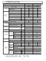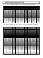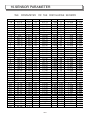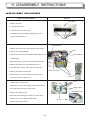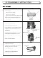
1
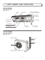
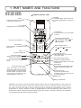
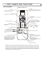
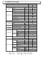
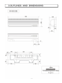
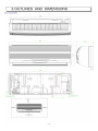
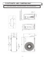
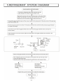
SPLIT TYPE INVERTER AIR CONDITIONER SERVICE MANUAL KFR - 3601GW/BPE KFR- 40 01GW/BPE KFR- 3502GW/BPE CONTENTS 1.PART NAMES AND FUNCTIONS.................. 2.SPECIFICATION......................................... 3.OUTLINES AND DIMENSIONS..................... 4.WIRING DIAGRAM...................................... 5.REFRIGERANT SYSTEM DIAGRAM............. 6.PERFORMANCE DATA................................ 7.CONTROL MODE ....................................... 8.TROUBLESHOOTING.................................. 9.SERVICE FLOW CHART............................. 10.SENSOR PARAMETER............................. 11.DISASSEMBLY INSTRUCTIONS................. 12.PARTS LIST.............................................. 1. PART NAMES AND FUNCTIONS KFR-3601G/BPE KFR-4001 G /BPE INDOOR UNIT Air filter Air fresh filter Indoor coil sensor(inside) Switch button Front cover VFD screen Air inlet grille Horizontal Vane Air outlet Vertical Vane Power plug KFR-3601W/BPE KFR-4001W/BPE OUTDOOR UNIT Air inlet (rear and side) Tubes and cable Drainage hose Air outlet Drainage hole (bottom) 1 1. PART NAMES AND FUNCTIONS KFR-3502G/BPE INDOOR UNIT Air inlet Air filter Front panel Horizontal Vane Color display screen Air outlet Power plug Vertical vane KFR-3502G/BPE OUTDOOR UNIT Air inlet (rear and side) Tubes and cable Drainage hose Air outlet Drainage hole(bottom) 2 1. PART NAMES AND FUNCTIONS KFR-3601G/BPE KFR-4001 G /BPE REMOTE CONTROL UNIT Transmitter Transmitting signals to the indoor unit, the symbol will appear on the top of LCD. Sensor Testing the ambient temperature of the remote control unit LCD Displaying the running condition. T.SETTING A C 1Ê Ð± ¡ A HOUR A ON Hi-power running button Flap Up-down adjustment Timer on/off button Setting the time of appliance on/off. Set/cancel timer button Set or cancel the time of appliance on/off. A OFF H.P. Sleep button Press the button, the appliance enter sleep mode. On/Off button Press the button to run, press again to cease. ON/OFF TEMP. Temperature setting button Press the button marked " "or " " to increase or decrease the temperature. Mode selection button SLEEP Auto heating Fan MODE FLAP ON FAN/MUTE ATR EX. OFF dehumidification cooling Air exchange button When this function works, the air can be keep fresh. Fan speed selection button SET BATTERY CLR SOFT SENSOR TEMP.DISP RESET Temperature displaying button setting the temperature in the screen of indoor unit Reset button Press the button after batteries are loaded and indication appears on LCD. A/C sensor button Press the button if the remote control unit is liable to be affected by the heat resource, such as electric blanket, radiator or sunlight, this will use the sensor of indoor unit, the symbol will appear on the LCD. Duel energy-saving This function can be used for Restricting the max. electric current by control software. Sliding cover Battery compartment REMARK: The remote controller transmits signal to indoor unit at 3 minutes intervals. If the indoor unit has not received the signal for more than 10 minutes due to remote controller missing or other reason, the sensor on indoor unit will be used for detecting indoor temperature automatically. Here, ambient temperature of remote controller is likely to slightly different from that detecting by the indoor unit, temperature will be compensated automatically. When the remote controller is missing or the batteries are exhausted, please use the temporary switch. 3 1. PART NAMES AND FUNCTIONS KFR-3502G/BPE REMOTE CONTROL UNIT Transmitter Transmitting signals to the indoor unit, the symbol will appear on the top of LCD. Sensor Testing the ambient temperature of the remote control unit LCD Displaying the running condition. T.SETTING A C A 1 HOUR HOUR A ON Hi-power running button OFF H.P. Sleep button Press the button, the appliance enter sleep mode. Flap Up-down adjustment Timer on/off button Setting the time of appliance on/off. Set/cancel timer button Set or cancel the time of appliance on/off. On/Off button Press the button to run, press again to cease. A ON/OFF TEMP. Temperature setting button Press the button marked " "or " " to increase or decrease the temperature. Mode selection button SLEEP Auto heating Fan cooling MODE FLAP ON dehumidification FAN/MUTE OFF Fan speed selection button SET BATTERY CLR SENSOR SOFT RESET Reset button Press the button after batteries are loaded and indication appears on LCD. A/C sensor button Press the button if the remote control unit is liable to be affected by the heat resource, such as electric blanket, radiator or sunlight, this will use the sensor of indoor unit, the symbol will appear on the LCD. Duel energy-saving This function can be used for Restricting the max. electric current by control software. Sliding cover Battery compartment REMARK: The remote controller transmits signal to indoor unit at 3 minutes intervals. If the indoor unit has not received the signal for more than 10 minutes due to remote controller missing or other reason, the sensor on indoor unit will be used for detecting indoor temperature automatically. Here, ambient temperature of remote controller is likely to slightly different from that detecting by the indoor unit, temperature will be compensated automatically. When the remote controller is missing or the batteries are exhausted, please use the temporary switch. 4 2.SPECIFICATION Model Function Power Capacity Electrical data supply KFR-3601GW/BPE KFR-4001GW/BPE Cooling Cooling a.c 220V~ 50Hz 4.0 KW 3.6 Dehumidification l /h 1.5 3 5.0 1.8 m /h 540 650 630 680 Power outlet A 16 16 16 16 Running current A 6.35 7.8 8.0 11.5 Power input W 1.34 1.58 1.54 2.14 Auxiliary heater A(KW) ----- ----- ----- ----- Power factor % 90 90 90 90 Starting current A 17 17 Compressor motor current A 6.2 6.2 Fan motor current A 0.2 0.2 Compressor Output 2.68 3.16 Winding resistance (at20°Ñ) Model 1100 1100 1.05 1.05 YYW16-4-411 YYW16-4-411 340 ( main) 340 ( main) 395(assisitant) 395(assisitant) UE6T-C41A4 UE6T-C41A4 151.4 151.4 860 860 Winding resistance (at20°Ñ) Width mm Indoor unit Height mm 285 285 Depth mm 235 235 Width mm 800 800 Outdoor unit Height mm 555 555 Depth mm 260 260 Indoor unit kg 11.5 11.5 Outdoor unit kg 39.0 39.0 6 6 Dimensions Air direction Special remarks 2.8 SGZ20EG2UY W Model 2.6 SGZ20EG2UY Winding resistance (at20°Ñ) Weight 6.0 Air flow Model Outdoor fan motor Heating a.c 220V~ 50Hz Capacity Coefficient of performance(C.O.P) Indoor fan motor Heating Sound lever Indoor unit (Hi) Outdoor unit dB 39 40 42 43 dB 48 49 48 49 Fan speed (Hi) Indoor unit rpm 1100 1200 1220 1250 Outdoor unit rpm Fan speed regulator 680 680 Indoor unit 4 4 Outdoor unit 3 3 Refrigerant filling capacity(R-22) kg 1.10 1.18 RT1(at25°Ñ) k 58 58 Thermitstor RT2(at25°Ñ) k 5.3 5.3 RT3(at25°Ñ) k 5 5 NOTE :Test conditions Cooling : Idoor DB27 °Ñ/ WB19 °Ñ , Outdoor Heating: Indoor DB20 °Ñ/ WB15 °Ñ , Outdoor DB35°Ñ/ WB24 °Ñ DB7°Ñ / WB 6°Ñ 5 2.SPECIFICATION Model KFR-3502GW/BPE Function Power Capacity Electrical data Cooling supply a.c220 50Hz Capacity KW 3.5 4.8 Dehumidification l /h 1.8 —— 3 540 640 Air flow m /h Power outlet A Running current A 6.5 10.0 Power input W 7.8 12.0 Auxiliary heater A(KW) Power factor % Starting current A 20 Compressor motor current A 7.2 Fan motor current A 0.2 Coefficient of performance(C.O.P) 16 —— 90 W 650 Winding resistance (at20 °Ñ) Model Outdoor fan motor Model 3.0 SHV130FGEC Compressor Output Indoor fan motor 90 2.7 Model 0.87 YZW16W-4-411 Winding resistance (at20 °Ñ) KFR-3601GW/BPE UE6T-C41A4 Winding resistance (at20 °Ñ) 151.4 Width mm 285 Indoor unit Height mm 220 Depth mm 805 Width mm 316 Outdoor unit Height mm 555 Depth mm 867 Indoor unit kg 9.5 Outdoor unit kg 39 Dimensions Weight Heating Air direction 6 6 Sound lever Indoor unit (Hi) Outdoor unit dB 39/30 39/33 dB 48/41 48/41 Fan speed (Hi) Indoor unit rpm 1180 1230 Outdoor unit rpm 750 750 Special remarks Fan speed regulator Indoor unit 4 4 Outdoor unit 3 3 Refrigerant filling capacity(R-22) kg 1.15 RT1(at25°Ñ ) k 58 Thermitstor RT2(at25°Ñ ) k 5.3 RT3(at25°Ñ) k 5 NOTE :Test conditions Cooling : Idoor Heating: Indoor DB27 °Ñ/ WB19 °Ñ Outdoor DB35°Ñ/ WB24 °Ñ DB20 °Ñ/ WB15 °Ñ Outdoor DB7°Ñ / WB 6 °Ñ 6 5.REFRIGERANT 3.OUTLINES AND SYSTEM DIMENSIONS DIAGRAM KFR-3601W/BPE KFR-4001W/BPE KFR-3502W/BPE 9 4.WIRING DIAGRAM KFR-3601GW/BPE KFR-4001 GW /BPE ELECTRICAL WIRING DIAGRAM INDICATOR BOARD ELECTRICAL WIRING DIAGRAM CONTROL BOARD TERM.PANEL 0 (L) 1 (L) 2 (N) 3 4 (SI) BRN BLK WHT RED L E N EVAP. POWER TRAN. +5V(CN01.1) GND(CN01.2) CS(CN01.3) SO(CN01.4) CLK(CN01.5) REMOTE(CN01.6) +5V(CN08.1) GND(CN08.2) CS(CN08.3) AC IN1 SO(CN08.4) AC OUT1 SCK(CN08.5) ACIN2(CN06.2) REMOTE(CN08.6) SI(CN06.1) BRIGHT(CN02.1) -27V(CN02.2) 4.6B(CN02.3) 4.6A(CN02.4) POWER WIRE TRANSE(CN04.1) TRANSE(CN04.2) 4.6A(CN01.1) MID(CN01.2) 4.6B(CN01.3) 9V(CN01.4) 9V(CN01.5) AC22V(CN01.6) AC22V(CN01.7) TRANSE(CN05.1) TRANSE(CN05.2) BRIGHT(CN02.1) -27V(CN02.2) 4.6B(CN02.3) 4.6A(CN02.4) FLAPI(CN16.1) FLAPI(CN16.2) FLAPI(CN16.3) FLAPI(CN16.4) FLAPI(CN16.5) 1 2 3 4 5 STEP. MOTOR 1 FLAP2(CN17.1) FLAP2(CN17.2) FLAP2(CN17.3) FLAP2(CN17.4) FLAP2(CN17.5) 1 2 3 4 5 STEP. MOTOR 2 VCC(CN09.1) GND(CN09.2) VEN(CN09.3) 1 2 3 AIR EX. FAN FAN(CN07.1) FAN(CN07.2) FAN(CN07.3) 1 2 3 POWER TRAN. TRANSE(CN10.1) TRANSE(CN10.3) INDOOR SENSOR ROOM(CN20.1) ROOM(CN20.2) COIL(CN19.1) COIL(CN19.2) EVAP. SENSOR PHASE TEST +5V(CN11.1) PH(CN11.2) GND(CN11.3) 1 2 3 SW(CN15.1) GND(CN15.2) 1 2 FAN MOTOR FAN CAP. OUTDOOR UNIT BLK CAP(CN06.1) BLK CAP(CN06.2) ELECTRICAL WIRING DIAGRAM FUSE BLK CONTROL BOARD RED SI(CN09) BLK WHT IN2 YEL/GRN IN1 TERM. PANEL E OUT1 OUT2 YEL/GRN REC. BRIDGE WHT IPM BOARD VUPC(CN15.1) VUP1(CN15.2) VVPC(CN15.4) VVP1(CN15.5) VWPC(CN15.7) VWP1(CN15.8) VNC(CN15.10) VN1(CN15.11) FIL. BOARD 1 2 3 4 POWER SWITCH BLK WHT AC IN1(CN04) AC IN2(CN05) DC OUT1(CN11) DC OUT2(CN01) WHT AC OUT1(CN03) VUPC(CN12.1) VUP1(CN12.2) VVPC(CN12.4) VVP1(CN12.5) VWPC(CN12.7) VWP1(CN12.8) VNC(CN12.10) VN1(CN12.11) P(CN07) N(CN06) BRN BLK OUT3 W(CN03) + AC _ AC V(CN04) U(CN05) VFC(CN18.1) GND(CN18.2) +5V(CN18.3) Z(CN18.4) Y(CN18.5) X(CN18.6) W(CN18.7) V(CN18.8) U(CN18.9) DC IN1(CN02) SV(CNI0.1) SV(CNI0.2) YEL YEL CAP. ORG ORG ORG + ELEC. CAPACITOR 4-WAY VALVE RED WHT BLU FAN CAP(CN06.1) DC IN2(CN07) PTC FAN CAP(CN06.2) BLU YEL PTC BLU BLK FAN CAP. YEL PTC GAIKI(CN17.1) GAIKI(CN17.2) COIL(CN13.1) COIL(CN13.2) COMP(CN16.1) COMP(CN16.2) C(CN08.1) AC(CN08.2) H(CN08.3) M(CN08.4) L(CN08.5) OUTDOOR SENSOR CONDENSOR SENSOR DISCHARGE SENSOR OLP BLK R S T INDUCTOR VFC(CN05.1) GND(CN05.2) +5V(CN05.3) Z(CN05.4) Y(CN05.5) X(CN05.6) W(CN05.7) V(CN05.8) U(CN05.9) RED RED THERMO(CN12.1) THERMO(CN12.2) 10 COMPRESSOR YEL/GRN EARTH C AC H M L YEL/GRN EARTH FAN MOTOR 4.WIRING DIAGRAM KFR-3502G/BPE ELECTRICAL WIRING DIAGRAM ELECTRICAL WIRING DIAGRAM INDICATOR BOARD TERM.PANEL CONTROL BOARD 0 (L) 1 (L) 2 (N) 3 4 (SI) EVAP. BRN BLK WHT RED +5V(CN08.1) GND(CN08.2) CS(CN08.3) L IN SO(CN08.4) L OUT1 SCK(CN08.5) ACIN2(CN03.2) REMOTE(CN08.6) SW(CN08.7) SI(CN03.1) -27V(CN02.2) 4.6B(CN02.3) 4.6A(CN02.4) L E N +5V(CN01.1) GND(CN01.2) CS(CN01.3) SO(CN01.4) CLK(CN01.5) REMOTE(CN01.6) SW(CN01.7) -27V(CN02.1) 4.6B(CN02.2) 4.6A(CN02.3) POWER TRAN. POWER WIRE TRANSE(CN04.1) TRANSE(CN04.2) 4.6A(CN01.1) MID(CN01.2) 4.6B(CN01.3) 9V(CN01.4) 9V(CN01.5) AC22V(CN01.6) AC22V(CN01.7) FLAP2(CN17.1) FLAP2(CN17.2) FLAP2(CN17.3) FLAP2(CN17.4) FLAP2(CN17.5) 1 2 3 4 5 STEP MOTOR FAN MOTOR INDOOR SENSOR ROOM(CN20.1) ROOM(CN20.2) FAN(CN07.1) FAN(CN07.2) FAN(CN07.3) COIL(CN19.1) COIL(CN19.2) PHASE TEST +5V(CN11.1) PH(CN11.2) GND(CN11.3) EVAP. SENSOR 11 1 2 3 1 2 3 4.WIRING DIAGRAM KFR-3502W/BPE FUSE BLK BLK RED CONTROL BOARD IPM BOARD SI(CN09) FIL. BOARD 1 2 3 4 IN2 WHT YEL/GRN IN1 VNC(CN15.10) VN1(CN15.11) TERM. PANEL E OUT1 OUT2 YEL/GRN BLK WHT REC. BRIDGE P(CN07) N(CN06) BRN BLK OUT3 WHT W(CN03) AC AC + _ AC IN1(CN04) AC IN2(CN05) DC OUT1(CN11) DC OUT2(CN01) VNC(CN12.10) VN1(CN12.11) WHT AC OUT1(CN03) V(CN04) U(CN05) YEL YEL CAP. ORG ORG ORG + ELEC. CAPACITOR VFC(CN05.1) GND(CN05.2) +5V(CN05.3) Z(CN05.4) Y(CN05.5) X(CN05.6) W(CN05.7) V(CN05.8) U(CN05.9) 4-WAY VALVE RED WHT BLU BLU YEL FAN CAP(CN06.1) DC IN2(CN07) PTC FAN CAP(CN06.2) YEL CONDENSOR SENSOR DISCHARGE SENSOR BLU BLK FAN CAP. PTC OUTDOOR SENSOR BLK R S T INDUCTOR VFC(CN18.1) GND(CN18.2) +5V(CN18.3) Z(CN18.4) Y(CN18.5) X(CN18.6) W(CN18.7) V(CN18.8) U(CN18.9) DC IN1(CN02) SV(CNI0.1) SV(CNI0.2) PTC GAIKI(CN17.1) GAIKI(CN17.2) COIL(CN13.1) COIL(CN13.2) COMP(CN16.1) COMP(CN16.2) C(CN08.1) AC(CN08.2) H(CN08.3) M(CN08.4) L(CN08.5) COMPRESSOR YEL/GRN EARTH C AC N H M L YEL/GRN EARTH FAN MOTOR 12 5.REFRIGERANT SYSTEM DIAGRAM MAX. REFRIGERANT PIPING LENGTH Modles Refrigerant Piping Max. Length : m A Piping size O.D : mm Gas Liquid KFR-3502GW/BPE 15 12.7 6.35 KFR-3601GW/BPE 15 12.7 6.35 KFR-4001GW/BPE 15 12.7 6.35 Length of connecting pipe : m Indoor unit Outdoor unit MAX. HEIGHT DIFFERENCE Indoor unit ` Refrigerant piping Max. length A Max. Height difference 5m Outdoor unit ADDITIONAL; REFRIGERANT CHARGE(R-22 : g) Modles Outdoor unit precharged (up to 7m) Refrigerant piping length (one way) 7m 10m 15m KFR-3502GW/BPE 1150 0 75 200 KFR-3601GW/BPE 1100 0 75 200 KFR-4001GW/BPE 1180 0 75 200 14 COOLING CAPACITY model KFR-3601GW/BPE (220V/50Hz) KFR-3502GW/BPE (220V/50Hz) 20 25 30 35 40 45 CA PC CA PC CA PC CA PC CA PC CA PC 16 3787 1425 3671 1439 3420 1498 3123 1501 2855 1564 2649 1637 18 4117 1459 3876 1445 3775 1525 3475 1527 3244 1637 2879 1643 20 4301 1436 4160 1434 3947 1499 3644 1501 3367 1583 2958 1599 22 4492 1405 4326 1432 4223 1488 3930 1495 3632 1584 3235 1613 16 3622 1296 3425 1409 3308 1512 3000 1520 2775 1598 2473 1590 18 3665 1295 3330 1176 3380 1350 3068 1359 2789 1434 2433 1430 20 3811 1296 3792 1406 3633 1542 3417 1528 3128 1584 2792 1606 22 3908 1293 3941 1420 3882 1518 3600 1530 3370 1623 2973 1617 HEATING CAPACITY model Indoor Intake Air (DB°Ñ) Outdoor intake air WB°Ñ -15 -10 -5 0 5 10 15 CA PC CA PC CA PC CA PC CA PC CA PC CA PC KFR-3601 GW/BPE (220) 15 3452 1759 3871 1746 4242 1781 4792 1805 5362 1802 5209 1498 5619 1492 20 3341 1896 3694 1871 4027 1815 4447 1787 4908 1776 4857 1499 5230 1495 25 3257 1776 3465 1781 3697 1774 4198 1838 4576 1800 4488 1494 4844 1511 KFR-3502 GW/BPE 15 3462 1754 4075 1739 4627 1788 4780 1644 5133 1582 5123 1457 5017 1385 20 3362 1751 3861 1781 4285 1761 4545 1765 5022 1663 5092 1579 5113 1390 25 3265 1743 3638 1793 3963 1744 4296 1777 4706 1684 4934 1625 4991 1453 Note CA: Capacity(W) PA: Power consumption(Kw) 16 6.PERFORMANCE 6. PERFORMANCEDATA DATA Outdoor intake air DB°Ñ Indoor Intake Air (WB°Ñ) 7.CONTROL MODE 1. Automatic 1.1 When the air conditioner is switched on and the remote controller is set to Auto mode, the air conditioner will select running modes automatically according to the difference between the room temperature and the setting temperature. 1.2 The running mode will be set when the machine is first switched on. Once set, the running mode cannot be changed within 30 minutes. 1.3 If the difference between the room temperature and the setting temperature exceeds 3 degrees, change the running mode immediately. 1.4 If the machine is turned off and restarted using the remote controller, the above conditions are still good. 1.5 If the machine is powered off and restarted, the running mode must be re-selected. 1.6 The running frequency will be determined by the temperature difference. 2. Cooling 2.1 In the cooling mode, the preset temperature is determined by the remote controller. The temperature range is 16°Ñ—30°Ñ. 2.2 The compressor will start immediately when the machine is first powered on; it will take at least 3min for the compressor to restart if the machine is restarted. 2.3 The fan speed changes in auto mode. Tsetting- Tindoor Fan speed Tsetting- Tindoor Fan speed 0°Ñ Low 0°Ñ Low Temperature Temperature 1°Ñ Mid 1°Ñ Mid difference difference 2°Ñ Mid 2°Ñ Mid 3°Ñ 4°Ñ 5°Ñ 3°Ñ 4°Ñ 5°Ñ Mid Mid High Mid High High 2.4 Outdoor fan speed T outdoor 28°Ñ High T outdoor 28°Ñ Determined by the outdoor coil tube temperature T outdoor coil tube, when T outdoor coil tube 40°Ñ High 35°Ñ T outdoor coil tube 40°Ñ Mid T outdoor coil tube 35°Ñ Low 2.5 The four-way valve is off. Dehumidification 1.1 In the dehumidification mode, the temperature is determined by the remote controller. The temperature range is 16°Ñ—30°Ñ. The controller will determine the running mode according to the indoor and outdoor temperature difference. 1.2 When the room temperature is 2°Ñhigher than the preset temperature, cooling run will be started. When the temperature difference between the indoor and outdoor is lower than or equal to 2 °Ñ,the drying mode will be started. When running in the drying mode, the compressor will alternate between the low and high frequencies. 17 7.CONTROL MODE 1.1 In this mode, the outdoor fan will work as follows: Outdoor temperature 28°Ñ Outdoor temperature 28°Ñ and condenser temperature 40°Ñ High Outdoor temperature 28°Ñ and 40°Ñ condenser temperature 35°Ñ Mid Outdoor temperature 28°Ñ High Low Heating 1.1 In the heating mode, the set temperature is determined by the remote controller. The temperature range is 16°Ñ—30°Ñ. 1.2 The compressor will start immediately when the machine is switched on; it will take at least 3min for the compressor to restart if the machine is restarted. 1.3 If the compressor is started, it must run at least 5min. 1.4 When the air conditioner is switched off, the compressor will stop and the outdoor four-way valve will be delayed off. The remaining heat will be discharged by the indoor unit before it stops. 1.5 Cold air prevention. When the air conditioner is started, the indoor unit will not run immediately. It will not start until the indoor heat exchanger is warmed up. 1.6 During operation, when the preset temperature is met, the indoor compressor will stop to cause the indoor fan to stop. So when the compressor restarts, the cold air prevention will still be working. 1.7 In this mode, the outdoor fan will work as follows: Outdoor temperature 24°Ñ : 15°Ñ outdoor temperature Outdoor temperature 10°Ñ: Low 10°Ñ: Mid High 1.8 The four-way valve is in conducting state. 2. Defrosting 2.1 The defrosting is done through changing the flow direction of refrigerant inside of the four-way valve. 2.2 Defrosting conditions: Continuous heating run for more than 30min During single machine operation, T outdoor – T outdoor coil 7°Ñ and lasts 5 minutes 2.3 Defrosting process: Compressor and outdoor fan motor off four-way valve off compressor on defrosting conditions met compressor off four-way valve on compressor on outdoor fan on end 3. Ventilation(Fan mode) During fan operation, only the indoor fan and the flap are running in the setting mode. If the fan speed is set to Auto, it will enter in low-speed run. 18 7.CONTROL MODE 1. Energy-saving 4.1 Press the SOFT button on the remote controller to activate the energy-saving function. Now the energy-saving symbol appears on the screen. Press the button again to cancel this function, the corresponding symbol will go off. 4.2 During energy-saving mode, the electric current will be limited to 60% of the rating level through adjusting the compressor revolving frequency and limiting the maximum current. 4.3 This mode cannot be cancelled by the switching-on and off operations. When the machine is turned off, the energy-saving symbol will remain on. 2. Sleeping 5.1 During heating or cooling mode, press the SLEEP button on the remote controller, the sleeping mode can be set or cancelled and the sleeping symbol on the screen will light up or go off accordingly. 5.2 Heating: After this function is enabled, the setting temperature will fall down 3 degrees within an hour. Two hours later, the temperature will fall down another 4 degrees, and the machine will be turned off after running for another 5 hours. 5.3 Cooling: After this function is started, the setting temperature will rise 1 degree within an hour, and the machine will be turned off automatically after another 7 hours. 5.4 The default mode is sleeping off. The sleeping function will be cancelled after the machine is switched off. 3. High-power In this mode, the indoor fan speed will go into high level. The compressor runs at the max permissible frequency, which will be displayed on the screen. The original running mode will be automatically resumed after running for 15 minutes. 4. Temporary switch 7.1 If the remote controller is missing, press the temporary switch and the system starts in the automatic mode, press the switch again to stop the system. Automatic mode follows: A indoor temperature 26 °Ñ cooling mode temperature setting 26 °Ñ B indoor temperature 23 °Ñ heating mode temperature setting 26 °Ñ C 23°Ñ indoor temperature 26°Ñ fan mode Indoor fan speed is automatic in automatic mode. 7.2 Hold down the temporary switch for 5 seconds or longer and the system is forced to run in the cooling mode regardless of indoor temperature. NOTE: Operating frequency and rated values of the compressor: Item Hz Mode Cooling Heating KFR-3601GW/BPE KFR-4001GW/BPE KFR-3502GW/BPE Frequency range Rated frequency Frequency range Rated frequency Frequency range Rated frequency 30-110 30-137 84 96 30-110 30-137 94 112 15-110 15-137 82 92 19 7.CONTROL MODE Other functions 1. Flap control 1.1 Press the FLAP button on the remote controller continuously, the flap will alternate within the following eight positions: Auto, fixed (including the six positions of the flap from top to 1,2,3,4,5,6) and swing. 1.2 Auto: During the heating mode, the flap is set at position 5; during the cooling and dehumidification mode, the flap is at position 2; during the fan mode, it is at position 2. 1.3 Fixed: The position of the flap is fixed at a certain position by the remote controller. 1.4 Scanning: During cooling and fan mode, the flap sways among positions 1—4; during heating mode, the flap sways between positions 3—6. 1.5 The default mode is Auto. 1.6 When first turned on or turned off, the flap will turn to the furthermost positions to ensure well closing of the flap. When started, the flap will turn to the furthermost positions. After the grille is completely closed, it will turn to the setting position. 2. Man-machine communication 2.1 The indoor controller has two temperature sensors to detect the room temperature: one in the controller and the other at the air inlet of indoor unit. The default airflow setting depends on that detected by the remote controller. The remote controller detects room temperature once every 20 seconds and transmits signals once every 3 minutes or when the detected temperature is not the same. If the indoor controller cannot receive signals for more than 10 minutes, it will automatically start the temperature sensor at the air inlet of indoor unit. Meanwhile, the man-machine communication symbol on the screen will go off. 2.2 The man-machine communication mode cannot be cancelled by the switching-on and off operations. When the machine is switched off, the man-machine communication symbol will remain on. 2.3 When the machine is turned on, the man-machine communication symbol will appear. When the air conditioner is started by the switch button of indoor unit, the man-machine communication symbol will go off. 3. Timing on and off 3.1 Timing On: when the timing-on function is set by the remote controller, the timing-on function of the air conditioner is activated and the timer symbol lights up. When the setting time arrives, the machine starts with the setting mode after a signal from the remote controller is received. If no signal is received at the setting time, the machine will run by automatic settings. At the same time, the man-machine communication symbol goes off. 3.2 Timing Off: when the timing-off function is set by the remote controller, the timing-off function of the air conditioner is activated and the timer symbol lights up. When the setting time arrives, the machine shuts off after a signal from the remote controller is received. If no signal is received at the setting time, the machine will automatically shut off. At the same time, the man-machine communication symbol goes off. 3.3 The timing mode cannot be cancelled by the switching-on and off operations. When the machine is switched off, the timer symbol remains on. 20 8. TROUBLESHOOTING 1. Trouble code display When the controller creates protection, press the sensor button, the trouble codes will be displayed at the place for the indoor temperature on the VFD of the indoor unit. Once a trouble code appears due to the trouble of the air conditioner, it can not be cleared unless the machine is powered off. Trouble Code Table ( means the light diode lights up; means the diode goes off) Content of trouble Indoor display code Indoor sensor trouble 1 Evaporator sensor trouble 2 Evaporator freezing 3 Over hot of indoor heatexchanger 4 Communication trouble 5 Fan motor trouble 6 Air outlet sensor trouble 10 Lightness sensor trouble 11 Outdoor unit display LED02 2 Indoor unit E PROM trouble 13 Outdoor sensor trouble 21 Condenser sensor trouble 22 Over hot of compressor 23 Over current 26 Overload protection 27 Power voltage trouble 28 Momentary power failure 29 Overload of outdoor unit for cooling 30 Defrosting 31 IPM trouble LED03 LED04 33 2 Data failure of outdoor E PROM 33 2. Trouble code display when frequency is restricted when the protection function is in action, the compressor doesn’t work, only its frequency is restricted, the LED of outdoor unit displays the work condition. Serial number 1 2 3 4 5 6 7 Cause of frequency restriction In good condition Power voltage isn’t in normal range Overload of outdoor unit Over current of outdoor unit Exhaust over hot LED02 Evaporator freezing Setting frequency resistance 21 LED OF outdoor unit LED03 LED04 8. TROUBLESHOOTING 3. The content of trouble code display 3.1 Abnormal sensor: when the sensor is short circuited or cut off, the compressor will stop, and the trouble code will be displayed. 3.2 Abnormal power module IPM: when the power module comes about such problems as overheat, over current, short circuit, the compressor will stops, and the trouble code will be displayed. 3.3 Temperature protection for the compressor exhaust When the compressor exhaust temperature 90 °Ñ, the compressor runs at the ascending frequency; When the temperature 90 °Ñ, the compressor runs at the limit to the frequency ascending; When the temperature 106 °Ñ, the compressor runs at the descending frequency; When the temperature 117°Ñ, the compressor stops. 3.4 When the temperature protector at the top of the compressor functions, the compressor stops and the trouble code is displayed. 3.5 Total current overload protection Cooling mode Type KFR-3601GW/BPE KFR-4001GW/BPE KFR-3502GW/BPE Item Current Current Current Voltage Voltage Work condition of compressor Voltage Frequency up 1. 6.8 1.86 8.5 2.32 6.8 1.86 2. 8.3 2.27 10.0 2.73 8.3 2.27 3. 9.8 2.68 11.5 3.14 9.8 2.68 Frequency up restriction Frequency down 4. 12.0 3.28 15.0 4.10 12.0 3.28 Stop Heating mode Type KFR-3601GW/BPE KFR-4001GW/BPE KFR-3502GW/BPE Item Current Current Current Voltage Voltage Work condition of compressor Voltage Frequency up 1. 8.5 2.32 13.0 3.56 8.5 2.32 2. 10.0 2.73 14.5 3.97 10.0 2.73 3. 11.5 3.14 16.0 4.38 11.5 3.14 Frequency up restriction Frequency down 4. 14.0 3.83 17.0 4.65 14.0 3.83 Stop 22 8. TROUBLESHOOTING 3.6 Abnormal power supply voltage protection When the supply voltage is above 260V or below 150V, the compressor stops, and the trouble code is displayed. 3.7 Overhot protection for the indoor heat exchanger When the temperature of the indoor coil 70°Ñ, the compressor will stop; When the temperature 55°Ñ, the outdoor flow speed will turn to the low speed, and the compressor runs at the descending frequency; When the temperature 52°Ñ and 55°Ñ, the compressor will prohibit the frequency from rising. 3.8 Anti-frost protection for the indoor heat exchanger Refer to the cooling cycle. 3.9 Momentary interruption protection for power supply When the power supply lacks the cycle or is interrupted, the compressor stops running, and the trouble code is displayed. 3.10 Start delay protection: When restarting the machine, the start is delayed for 3 minutes for protection. 3.11 Communication trouble: when the outdoor unit is turned on, the indoor unit will shut down the indoor unit 3 minutes later if the indoor unit has not received an effective communication signal which returns from the outdoor unit. And at the same time the trouble code is displayed. After another 3 minutes, the outdoor will be powered on again. Once the communication returns to normal, the trouble code will be cleared. 3.12 The trouble in the indoor fan motor: when the indoor micro-computer, depending on the position of the rotor of the indoor motor, determines the motor is in stoppage, lock or abnormal vibration state, the micro-computer will cut off the driving signal of the indoor fan. 3 minutes later, it is restarted. If the trouble occurs 4 times within 30 minutes, the air conditioner will stop, and the trouble code will be displayed. It can not be restarted unless being powered on again. 23 6.PERFORMANCE 9.SERVICE 5.REFRIGERANT FLOWSYSTEM CURVES CHART DIAGRAM Swi t ch on t he power suppl y Does VFD scr een di spl ay Nor mal l y? Does i t r ecei ve t he si gnal of r emot e cont r ol l er ? Yes Yes St ar t up sel f - t est f unct i on No No Check t he r esul t I s t he f use bl own? I s r emot e cont r ol l er i n good condi t i on ? Yes No I s t he wi r es poor l y connect ed? Reconnect al l t he wi r es or r epl ace i t Yes Remot e cont r ol l er t r oubl e or r epl ace t he bat t er y No Yes Af t er r epl aci ng t he di spl ay boar d, I s t her e st i l l t roubl e? No Di spl ay boar d t r oubl e Yes No Check t he t r ansf or mer , I s r esi st ance of wi ndi ng 0( shor t ci r cui t ) or ¡ Þ £ öpen ci r cui t £ © £ ¿ No Repl ace t he t r ansf or mer Af t er r epl aci ng t he i ndoor boar d, I s t her e st i l l t roubl e? I ndoor cont r ol boar d t r oubl e No Yes Af t er r epl aci ng t he di spl ay boar d, I s t her e st i l l t roubl e? I s i ndoor cont r ol boar d short ci r cui t ? Yes Di spl ay boar d t r oubl e No No I s t he r esi st ence of sensor Nor mal ? Yes Repl ace t he i ndoor cont r ol boar d Yes Repl ace t he t emper at ur e sensor Tr oubl e code 2 I ndoor coi l sensor t r oubl e I ndoor cont r ol boar d t r oubl e Check and f i nd shor t ci r cui t or open ci r cui t among ot her component s suc h as t r ansf or mer or f an mot or ? I ndoor cont r ol boar d I s br oken and r epl ace i t Tr oubl e code 1 I ndoor t emper at ur e sensor t r oubl e Yes I s t he r esi st ence of sensor cor r ect ? Repl ace t he i ndoor cont r ol boar d Yes No Repl ace t he i ndoor coi l sensor 24 9.SERVICE 5.REFRIGERANT FLOWSYSTEM CHART DIAGRAM Tr oubl e code 4 i ndoor heat exchanger I s over l oad Tr oubl e code 3 I ndoor heat exchanger I s f r eezed I s i ndoor heat exchanger f r eezed No I s i ndoor heat exchanger ver y hot ? I ndoor coi l sensor No I s compressor st i l l r unni ng? Nor mal pr ot ect i on Yes Yes Swi ch of f t he power , st ar t up t he ai r condi t oner af t er t he i ce di sappear s Swi ch of f t he power , st ar t up t he ai r condi t oner i n 10 mi nut es I s i ndoor heat exchanger st i l l f r eezed? No I s t he system i n good condi t i on? Occur by chanc e Yes No Swi ch of f t he power , r epl ace t he out door cont r ol boar d and t hen st ar t up t he ai r condi t oner . Swi ch of f t he power , r epl ace t he out door cont r ol boar d and t hen st ar t up t he ai r condi t oner . I s t he system i n good condi t i on? I s t he system i n good condi t i on? Our door cont r ol boar d t r oubl e Yes No No I ndoor cont r ol boar d t r oubl e and r epl ace i t I ndoor cont r ol boar d t r oubl e and r epl ace i t Tr oubl e code 6 i ndoor f an mot or t r oubl e Set t he ai r condi t i oner oper at e i n f an mode I s i ndoor f an mot or r unni ng? Yes No Does t he sock et of i ndoor cont r ol boar d have power i nput ? Does f an mot or st op wi t h t he r emot e cont r ol l er Yes No No I ndoor cont r ol boar d t r oubl e and r epl ace i t Yes I s r esi st ance of mai n wi ndi ng 0( shor t ci r cui t ) or ¡ Þ £ öpen ci r cui t £ © £ ¿ Yes Fan mot or t r oubl e and r epl ace i t No Move t he axI s and cr oss f an by hand, do t hey r ot at e smoot hl y? I ndoor coi l sensor t r oubl e Yes Yes I s compressor st i l l r unni ng? No No Fan mot or t r oubl e and r epl ace i t 25 Fan mot or t r oubl e and r epl ace i t No Nor mal pr ot ect i on Yes Occur by chanc e Yes Our door cont r ol boar d t r oubl e 9.SERVICE 5.REFRIGERANT FLOWSYSTEM CHART DIAGRAM Tr oubl e code 5 communi cat i on t r oubl e Di spl ay boar d t r oubl e and r epl ace i t No Are al l t he l ead wi r es connec t ed bet ween i ndoor and out door uni t ? No Connect t he i ndoor and out door uni t agai n accor di ng t o t he wi r i ng di agr am I ndoor cont r ol boar d t r oubl e and r epl ace i t I s t he system i n good condi t i on? Yes I ndoor cont r ol boar d t r oubl e No Yes Does t he power i ndi cat or of out door cont r ol boar d l i ght up? Yes I s out door cont r ol boar d short ci r cui t ? No I s t he f use of 3. 15A bl own? Repl ace t he out door cont r ol boar d and st ar t up agai n I s t he system i n good condi t i on? I s I PM boar d short ci r cui t ? No Yes Our door cont r ol boar d t r oubl e Yes No Nor mal pr ot ect i on and r epl ace f use Yes Yes Repl ace I PM boar d and f use Our door cont r ol boar d t r oubl e and r epl ace i t No I s t he f use of 20A bl own? Yes connect i on wi r e t r oubl e No I s t he r eact or and wave f i l t er boar d open ci r cui t ? Yes The cont r ol sys t em of out door uni t has shor t ci r cui t t r oubl e, check t he connect i on wi r e, wave f i l t er boar d, out door cont r ol boar d, I PM, r ect i f i er and el ect r ol yse c apaci t or r epl ace t he t r oubl e uni t Repl ace t he t r oubl e uni t No Does t he r ect i f i er have t he al t er nat i ng cur r ent i nput ? Yes Rect i f i er t r oubl e and r epl ace i t No I s t he vol t age i nput of st ar t up r esi s t or cor r ect ? The st ar t up r esi st or I s over hot ? Yes Yes Wave f i l t er boar d and r epl ace i t No I s t he f use i n cont r ol box of 20A brok en? Connect i on wi r e t r oubl e Yes No I s t her e power i nput bet ween 1 and 2 on t er mi nal panel of out door uni t ? Yes Ther e have some shor t ci r cui t behi nd t he st ar t up r esi st or Yes Connect i on wi r e t r oubl e and check Connect i on wi r e t r oubl e and check No I s t her e t he power out put of i ndoor uni t mai n r el ay( RY01)? Yes Connect i on wi r e t r oubl e and check No I ndoor cont r ol boar d and r epl ace i t The I PM. cont r ol and wave f i l t er boar d I s br oken or shor t ci r cui t The cont r ol sys t em of out door uni t has shor t ci r cui t t r oubl e, check t he connect i on wi r e, wave f i l t er boar d, out door cont r ol boar d, I PM, r ect i f i er and el ect r ol yse c apaci t or No I s t her e power out put bet ween 1 and 2 on t er mi nal panel of i ndoor uni t ? Repl ace i t Yes No I s wave f i l t er boar d open ci r cui t ? No 26 Repl ace t he t r oubl e uni t Repl ace t he t r oubl e uni t 9.SERVICE 5.REFRIGERANT FLOWSYSTEM CHART DIAGRAM Tr oubl e code 23 compr ssor over hot pr ot ect i on I s t he sur f ace of compr essor ver y hot ? Tr oubl e code 26 over cur r ent t r oubl e Yes I s t he oper at i ng cur r ent beyond Nor mal r ange? Nor mal pr ot ect i on Yes Nor mal pr ot ect i on No No I s t he OLP of compr ssor open ci r cui t ? Swi ch of f and st ar t up agai n, I s i t ok? Yes Yes Repl ace t he OLP Swi ch of f and st ar t up agai n, I s i t ok? Yes Occur by chanc e Yes Out door cont r ol boar d t r oubl e No No I s t he r esi st ance of compr essor di schar gi ng sensor cor r ect ? Repl ace di schar gi ng sensor No Repl ace t he out door cont r ol boar d, I s i t ok? No Yes Out door wave f i l t er boar d t r oubl e and r epl ace i t Out door cont r ol boar d t r oubl e and r epl ace i t Tr oubl e code 27 None l oad t r oubl e I s t he compr essor r unni ng? Repl ace t he out door cont r ol boar d, I s i t ok? Yes No Yes Out door cont r ol boar d No Do t her e have vol t age out put bet ween I PM and UVW ? Yes Compr essor t r oubl e Out door wave f i l t er boar d t r oubl e and r epl ace i t No I s t he vol t age of bet ween I PM and P¡ ¢ N cor r ect ? Yes Tr oubl e code 29 power suppl y f ai l moment ar y I PM t r oubl e and r epl ace i t No Swi t ch of f t he power suppl y and st ar t up i n 3 mi nut es Wave f i l t er boar d t r oubl e and r epl ace i t Are t her e mi s- wr i ng, poor cont act , or di sconnec t i on among t he sock et , i ndoor uni t and out door uni t ? Tr oubl e code 28 vol t age of power suppl y I s abNormal Yes Reconnect wi r es or r epai r t he sock et No I s t he vol t age of power suppl y Normal ? No swi ch of f and st ar t up agai n, I s i t ok? Nor mal pr ot ect i on Yes No Out door cont r ol boar d t r oubl e and r epl ace i t Repl ace t he out door cont r ol boar d, I s i t ok? Yes Out door cont r ol boar d t r oubl e 27 Yes Does t hI s t r oubl e st i l l appear ? Yes No No The vol t age of power suppl y I s out of Nor mal r ange 9.SERVICE 5.REFRIGERANT FLOWSYSTEM CHART DIAGRAM Tr oubl e code 30 condenser over l oad Tr oubl e code 11 l i ght ness s ensor t r oubl e I s t he out door heat exchanger r eal l y hot ? Yes Are al l t he wi r es connect ed bet ween t he i ndoor cont r ol boar d and di spl ay boar d? Nor mal pr et ect i on No Yes Reconnect or r epl ace t he wi r es No I s t he r esi st ance of out door coi l sensor cor r ect ? No I s t her e ok af t er r epl aci ng t he di spl ay boar d? Out door coi l sensor t r oubl e Yes Yes Di spl ay boar d t r oubl e and r epl ace i t No Out door cont r ol boar d and r epl ace i t I ndoor cont r ol boar d t r oubl e and r epl ace i t Tr oubl e code 32 I PM t r oubl e Does t he t r oubl e di appear i n 3 mi nut es ? Yes I PM t r oubl e appear f r equent l y? I s t he I PM r adi at or ver y hot ? Yes No Yes No I s t he I PM r adi at or ver y hot ? Nor mal pr ot ect i on Yes St ar t up t he ai r condi t i oner i n 30 mi nut es, doen i t wor k Normal l y? I PM t r oubl e appear f r equent l y? Yes Yes No I PM t r oubl e and r epl ace i t Repl ace t he wave f i l t er boar d, Does t hI s t r oubl e di sappear ? No Yes Tr oubl e code 13 EEPROM t r oubl e Tr oubl e code 33 EEPROM t r oubl e Tr oubl e code 21 out door t emper at ur e sensor t r oubl e I ndoor cont r ol boar d t r oubl e and r epl ace i t Wave f i l er t r oubl e and r epl ace i t Out door cont r ol boar d t r oubl e I s t he r esi st ance of sensor cor r ect ? Yes Out door cont r ol boar d t r oubl e and r epl ace i t No Out door t emper at ur e sensor t r oubl e and r epl ace i t Tr oubl e code 22 out door coi l sensor t r oubl e Yes Nor mal pr ot ect i on No No Assur e good vent i l at i on of out door uni t and good cont act bet ween I PM and r adi at or I s t he r esi st ance of sensor cor r ect ? Yes No Out door t emper at ur e sensor t r oubl e and r epl ace i t 28 Out door cont r ol boar d t r oubl e and r epl ace i t No Repl ace t he out door cont r ol boar d, Does t hI s t r oubl e di sappear ? Yes Out door cont r ol boar d t r oubl e 6.PERFORMANCE 9.SERVICE 5.REFRIGERANT FLOWSYSTEM CURVES CHART DIAGRAM KFR-3502G/BPE Indoor electric control P.C. Board 29 6.PERFORMANCE 9.SERVICE 5.REFRIGERANT FLOWSYSTEM CURVES CHART DIAGRAM KFR-3601G/BPE Indoor electric control P.C. Board 30 6.PERFORMANCE 9.SERVICE 5.REFRIGERANT FLOWSYSTEM CURVES CHART DIAGRAM KFR-3502W/BPE KFR-3601W/BPE KFR-4001W/BPE Outdoor electric control P.C. Board 31 10.SENSOR PARAMETER THE PARAMETER OF THE INDOOR SENSOR T ( 'c ) R(Ko) V ( v) T ( 'c ) R(Ko) V ( v) T ( 'c ) R(Ko) V ( v) - 10 -9 -8 -7 -6 -5 -4 -3 -2 -1 0 1 2 3 4 5 6 27. 68 26. 22 24. 85 23. 56 22. 34 21. 19 20. 11 19. 09 18. 12 17. 21 16. 35 15. 54 14. 77 14. 05 13. 36 12. 72 12. 1 0. 7258 0. 76 0. 7953 0. 8316 0. 8691 0. 9077 0. 9472 0. 9878 1. 0298 1. 0726 1. 1164 1. 1611 1. 207 1. 2533 1. 3012 1. 349 1. 3988 7 8 9 10 11 12 13 14 15 16 17 18 19 20 21 22 23 11. 52 10. 97 10. 45 9. 963 9. 497 9. 056 8. 638 8. 241 7. 865 7. 508 7. 169 6. 847 6. 541 6. 251 5. 975 5. 712 5. 463 1. 4488 1. 4997 1. 5512 1. 6027 1. 6553 1. 7083 1. 7619 1. 8159 1. 8703 1. 925 1. 9799 2. 0352 2. 0906 2. 1459 2. 2014 2. 257 2. 3123 24 25 26 27 28 29 30 31 32 33 34 35 36 37 38 39 40 5. 226 5 4. 785 4. 581 4. 387 4. 202 4. 025 3. 857 3. 697 3. 545 3. 399 3. 26 3. 128 3. 002 2. 881 2. 766 2. 657 2. 3675 2. 4227 2. 4776 2. 5321 2. 5861 2. 6399 2. 6934 2. 7463 2. 7986 2. 8502 2. 9016 2. 9523 3. 002 3. 0512 3. 0999 3. 1476 3. 1942 THE PARAMETER OF THE COIL AND OUTDOOR SENSOR T ( 'c ) R(Ko) V ( v) T ( 'c ) R(Ko) V ( v) T ( 'c ) - 20 - 19 - 18 - 17 - 16 - 15 - 14 - 13 - 12 - 11 - 10 -9 -8 -7 -6 -5 -4 -3 -2 -1 0 1 2 3 4 5 6 7 8 39. 58 37. 58 35. 69 33. 91 32. 23 30. 65 29. 15 27. 74 26. 4 25. 14 23. 95 22. 82 21. 75 20. 74 19. 79 18. 88 18. 02 17. 2 16. 43 15. 7 15 14. 34 13. 71 13. 11 12. 55 12. 01 11. 5 11. 01 10. 55 0. 5307 0. 5558 0. 5818 0. 6087 0. 6363 0. 6648 0. 6942 0. 7244 0. 7556 0. 7875 0. 8202 0. 8539 0. 8885 0. 9237 0. 9596 0. 9966 1. 0343 1. 0731 1. 1122 1. 152 1. 1929 1. 2342 1. 2765 1. 3195 1. 3623 1. 4063 1. 4506 1. 4959 1. 541 9 10 11 12 13 14 15 16 17 18 19 20 21 22 23 24 25 26 27 28 29 30 31 32 33 34 35 36 37 10. 1 9. 684 9. 284 8. 903 8. 54 8. 194 7. 864 7. 549 7. 249 6. 962 6. 688 6. 427 6. 178 5. 939 5. 712 5. 494 5. 286 5. 086 4. 896 4. 714 4. 539 4. 372 4. 212 4. 059 3. 912 3. 772 3. 637 3. 508 3. 384 1. 5878 1. 6338 1. 6805 1. 7276 1. 7749 1. 8226 1. 8704 1. 9185 1. 9667 2. 0151 2. 0636 2. 112 2. 1603 2. 2089 2. 257 2. 3053 2. 3533 2. 4014 2. 4489 2. 4963 2. 5436 2. 5904 2. 6369 2. 683 2. 7288 2. 7738 2. 8188 2. 8631 2. 907 38 39 40 41 42 43 44 45 46 47 48 49 50 51 52 53 54 55 56 57 58 59 60 61 62 63 64 65 32 R(Ko) 3. 3. 3. 2. 2. 2. 2. 2. 2. 2. 2. 2. 2. 2. 2. 1. 1. 1. 1. 1. 1. 1. 1. 1. 1. 1. 1. 1. 265 151 041 936 835 739 646 556 471 388 309 233 159 089 021 956 893 832 774 718 664 612 562 513 467 422 379 337 V ( v) 2. 9504 2. 9932 3. 0358 3. 0775 3. 1188 3. 159 3. 199 3. 2387 3. 2771 3. 3155 3. 3528 3. 3896 3. 4262 3. 4615 3. 4965 3. 5306 3. 5644 3. 5977 3. 6299 3. 6616 3. 6926 3. 7231 3. 7528 3. 7824 3. 8106 3. 8386 3. 8658 3. 8927 10.SENSOR PARAMETER THE PARAMETER OF THE DISCHARGE SENSOR T ( 'C ) R(O) V ( v) T ( 'C ) R(O) V ( v) T ( 'C ) R(O) V ( v) - 10 -9 -8 -7 -6 -5 -4 -3 -2 -1 0 1 2 3 4 5 6 7 8 9 10 11 12 13 14 15 16 17 18 19 20 21 22 23 24 25 26 27 28 29 30 313. 4 297. 2 281. 9 267. 5 253. 9 241. 1 229 217. 6 206. 8 196. 6 186. 9 177. 8 169. 2 161 153. 3 146 139 132. 5 126. 3 120. 4 114. 8 109. 5 104. 4 99. 66 95. 13 90. 82 86. 74 82. 85 79. 16 75. 65 72. 32 69. 15 66. 13 63. 27 60. 54 57. 94 55. 46 53. 11 50. 86 48. 72 46. 68 0. 3 0. 315 0. 331 0. 348 0. 365 0. 383 0. 402 0. 421 0. 441 0. 462 0. 483 0. 506 0. 529 0. 552 0. 577 0. 602 0. 629 0. 656 0. 684 0. 712 0. 742 0. 772 0. 804 0. 836 0. 869 0. 902 0. 937 0. 972 1. 008 1. 045 1. 083 1. 122 1. 161 1. 201 1. 242 1. 283 1. 325 1. 368 1. 411 1. 455 1. 5 31 32 33 34 35 36 37 38 39 40 41 42 43 44 45 46 47 48 49 50 51 52 53 54 55 56 57 58 59 60 61 62 63 64 65 66 67 68 69 70 44. 74 42. 89 41. 13 39. 44 37. 84 36. 3 34. 84 33. 44 32. 11 30. 83 29. 61 28. 45 27. 34 26. 27 25. 25 24. 28 23. 35 22. 46 21. 6 20. 79 20. 01 19. 26 18. 54 17. 85 17. 19 16. 56 15. 96 15. 38 14. 82 14. 29 13. 78 13. 28 12. 81 12. 36 11. 93 11. 51 11. 11 10. 73 10. 36 10 1. 545 1. 59 1. 636 1. 682 1. 729 1. 776 1. 823 1. 871 1. 919 1. 967 2. 016 2. 064 2. 112 2. 161 2. 21 2. 258 2. 307 2. 355 2. 404 2. 452 2. 499 2. 547 2. 595 2. 642 2. 689 2. 735 2. 781 2. 826 2. 872 2. 916 2. 96 3. 005 3. 048 3. 09 3. 132 3. 174 3. 214 3. 254 3. 294 3. 333 71 72 73 74 75 76 77 78 79 80 81 82 83 84 85 86 87 88 89 90 91 92 93 94 95 96 97 98 99 100 101 102 103 104 105 106 107 108 109 110 9. 659 9. 331 9. 016 8. 712 8. 421 8. 14 7. 869 7. 609 7. 359 7. 118 6. 885 6. 662 6. 446 6. 239 6. 039 5. 846 5. 661 5. 482 5. 309 5. 143 4. 982 4. 827 4. 678 4. 534 4. 395 4. 261 4. 132 4. 007 3. 886 3. 77 3. 658 3. 549 3. 444 3. 343 3. 15 3. 059 2. 97 2. 884 2. 802 2. 721 3. 372 3. 409 3. 446 3. 483 3. 519 3. 554 3. 588 3. 622 3. 655 3. 688 3. 72 3. 751 3. 781 3. 811 3. 84 3. 869 3. 897 3. 924 3. 951 3. 977 4. 003 4. 028 4. 052 4. 076 4. 099 4. 122 4. 144 4. 165 4. 187 4. 207 4. 227 4. 246 4. 265 4. 284 4. 32 4. 337 4. 354 4. 37 4. 386 4. 401 33 11. DISASSEMBLY INSTRUCTIONS KFR-3601G/BPE KFR-4001G/BPE OPERATION PROCEDURE PHOTOS Front Panel 1. Remove the grille 1) Open the front panel. 2) Take out the screws in the grille. 3) Hold the both sides of the grille, dragging towards oneself and then remove it. Screws 2. Remove the electrical control box Sensor Bracket 1) Remove the indoor coil sensor from the sensor bracket. Screw 2) Remove the switching board. 3) Take out the screws of the terminal board then Remove the Terminal Board terminal board. 4) Disconnect all the circuitry of the printed circuit board. 5) Remove the printed circuit board and check-up it. 6) Disconnect the circuitry in the electrical control box. Indoor Coil Sensor 7) Remove the printed circuit board. 8) Take out the screws of the electrical control box and Screws remove the electrical control box. Screws 3. Remove the air outlet frame 1) Take out the screws of the stepper motor and disconnect Stepper Motor the stepper motor and the air outlet frame. Drainage Hose 2) Remove the stepper motor. 3) Disconnect the drainage hose and the air outlet frame. 4) Take out the screws of the air outlet frame. Screws 5) Remove the air outlet frame. 34 11. DISASSEMBLY INSTRUCTIONS KFR-3601G/BPE KFR-4001G/BPE 4. Remove the evaporator 1) Disconnect the evaporator and the other parts then remove Screws the screws of the evaporator. 2) Remove the evaporator. Fan Motor Motor Cover 5. Remove the cross-flow fan and the fan motor 1) Take out the screws of the motor cover and remove the cover. 2) Remove the cross-flow fan and the fan motor. Cross-Flow Fan Screws 35 11. DISASSEMBLY INSTRUCTIONS KFR-3502G/BPE OPERATION PROCEDURE PHOTOS Front panel 1. Remove the grille Grille 1) Open the screw cover in the grille. 2) Take out the screws of the grille. 3) Hold the both sides of the front panel and drag it towards oneself, shown the switching board of the indoor unit. 跡掑蹟隊 4) Remove the grille. Grille Screws 2. Remove the electrical control box 1) Remove the electrical control box cover. 2) Remove the indoor coil sensor from the sensor bracket. 3) Take out the screws of the terminal and remove the Electrical Control Box Cover Terminal terminal board. Terminal Screw 4) Disconnect all connectors on the printed circuit board. Indoor Coil Sensor 5) Remove the printed circuit board and check-up it. 6) Disconnect the circuitry in the electrical control box. 7) Take out the screws of the electrical control box and Screws remove the electrical control box. 3. Remove the air outlet frame 1) Take out the screws of the stepper motor, disconnect Display Board the stepper motor and the air outlet frame. 2) Remove the stepper motor. 3) Disconnect the drainage hose and the air outlet frame. 4) Take out the screws of the air outlet frame. Stepper Motor 5) Remove the air outlet frame. 36 11. DISASSEMBLY INSTRUCTIONS KFR-3502G/BPE 4.Remove the evaporator 1) Disconnect the evaporator and the other parts, take out the screws of the evaporator. Evaporator 2) Remove the evaporator. Screws 5. Remove the fan motor and the cross-flow fan 1) Take out the screw of the rubber cover and remove the Rubber Cover rubber cover. 2) Remove the screw connecting the fan motor and the Cross-Flow Fan cross-flow fan. 3) Remove the fan motor and the bearing ass'y. 4) Remove the cross-flow fan. Cross-Flow Fan Screws 37 Fan Motor 11. DISASSEMBLY INSTRUCTIONS KFR-3502W/BPE,KFR-3601W/BPE,KFR-4001W/BPE OPERATION PROCEDURE PHOTOS Top Cover Screw Handle Screw Screw 1. Remove the top panel Valve Cover Screw Screw 1) Take out the screws of the top panel. 2) Remove the top panel. Screw Screw Screw Strengthen Plate Screw Screw 2. Remove the front panel Back Panel 1) Take out the screws of the front panel. 2) Take out the screws of the strengthen plate and remove the Screw Screw strengthen plate. Front Panel 3) Take out the screws of the electrical control box. 4) Remove the front panel. Screw 3. Remove the electrical control box Screw 1) Take out the screws of the valve cover and remove the Screw valve cover. 2) Take out the screws of the handle and remove the handle. 3) Disconnect the electrical control box and the other parts. 4) Take out the screws of the electrical control box. 5) Remove the electrical control box. Screw Screw 38 11. DISASSEMBLY INSTRUCTIONS KFR-3502W/BPE,KFR-3601W/BPE,KFR-4001W/BPE 4. Remove the back panel 1) Take out the screws of the back panel. 2) Remove the back panel. 5.Remove the fan ,fan motor,fan supporter and the partition Fan Supporter Fan plate. 1) Take out the screws of the fan and remove the fan. 2) Take out the screws of the fan motor and remove the fan motor. 3) Take out the screws of the fan supporter and remove the fan supporter. 4) Take out the screws of the partition plate and remove Screw Screw the partition plate. Screw Seperator Support Plate Condenser ass'y Compreesor ass'y 6. Check-up the other parts of the outdoor units 1) Check-up the condenser ass'y. 2) Check-up the compreesor ass'y. 3) Check-up the barrier ass'y. 4) Check-up the base ass'y. Barrier ass'y Screw Base ass'y 39 1 2 5 29 28 7 40 26 4 22 25 9 24 23 31 35 21 30 12 34 33 32 14 36 20 37 13 19 15 18 40 38 39 17 16 KFR-3601G/BPE KFR-4001G/BPE 27 3 6 8 10 11 12. PARTS LIST 12. PARTS LIST KFR- 3601G/ BP Key NO. 1 2 3 4 5 6 7 8 9 10 11 12 13 14 15 16 17 18 19 20 21 22 23 24 25 26 27 28 29 30 31 32 33 34 35 36 37 38 39 40 KFR- 4001G/ BP Description Front Panel Air Filter Electrical Control Box cover Display panel Grille Water Plate Evaporator Supporter Evaporator Ass’y Bearing Ass’y Cross-Flow Fan Ass’y Down Left Cover Base Ass’y Insulator Cover Ass’y Quantity 1 2 1 1 1 2 1 1 1 1 1 1 1 Mounting Plate 1 1 1 1 1 1 1 2 1 1 1 1 9 1 1 1 1 1 1 1 1 1 1 1 1 1 Installation Plate Exchange Ass’y Mounting Plate Down Right Cover Fan Motor Motor Guard Air Outlet Frame Stepper Motor Drainage Hose Ass’y Vane Install Plate Ass’y Short Vane Lever Long Vane Lever Vane Down Flap Up Flap Sensor Bracket Indoor Coil Sensor Terminal Power Transformer Transformer Fixing Plate Power Cable Display board Electrical Control Box Control Board Switching Ass’y Remote Controller 41 Part NO. RZA-2-1601-003-XX-0 RZA-0-2305-005-XX-0 RZA-2-2369-006-XX-0 RZA-0-2258-003-XXRZA-0-1501-004-XX-0 RZA-0-2326-102-XX-0 RZA-2-2219-014-XX-0 RZA-0-0055-033-XX-0 RZA-0-2510-100-XX-0 RZA-0-2509-100-XX-0 RZA-2-2369-007-XX-0 RZA-0-2201-101-XX-0 RZA-0-2209-016-XX-0 RZA-2-2478-100-XX-0 RZA-2-2230-100-XX-0 RZA-0-2538-001-XX-0 RZA-2-2362-018-XX-0 RZA-2-2369-008-XX-0 RZA-0-0000-046-XX-0 RZA-0-2514-102-XX-0 RZA-0-1504-016-XX-0 RZA-0-0000-048-XX-0 RZA-0-1303-100-XX-0 RZA-0-1514-011-XX-0 RZA-2-1514-009-XX-0 RZA-2-1514-013-XX-0 RZA-2-1519-003-XX-0 RZA-2-1523-005-XX-0 RZA-2-1523-004-XX-0 852-2-5303-215-01-0 RZA-0-5259-051-XX-0 RZA-0-5706-025-XX-0 RZA-0-5263-022-XX-0 RZA-2-2222-008-XX-0 RZA-0-5250-035-XX-A RZA-0-5172-146-XX-A RZA-0-5301-020-XX-0 RZA-0-5172-145-XX-0 RZA-0-5152-023-XX-A RZA-0-0054-044-XX-D 23 4 1 2 3 12 5 7 6 42 10 11 13 19 20 14 18 17 16 15 24 8 22 21 KFR-3601W/BPE KFR-4001W/BPE KFR-3502W/BPE 9 12. PARTS LIST 12. PARTS LIST KFR- 3502W/ BPE KFR- 3601W/ BPE KFR- 4001W/ BPE Key NO. Description 1 Fan Guard Ass’y Part NO. 852-2-1321-156-01-0 2 Cabinet Ass’y 852-2-1112-241-01-0 3 Propeller Fan Ass’y 852-2-2502-136-01-0 4 Fan Motor RZA-0-0000-031-XX-0 5 Mounting Plate Ass’y 852-2-2354-205-01-0 6 Condenser Ass’y 852-0-4102-076-00-0 7 Top Panel Ass’y 852-0-2309-152-00-0 8 Back Panel Ass’y 852-2-1120-247-01-0 9 Compressor Ass’y RZA-0-4526-055-XX-0 9 Compressor Ass’y RZA-0-4526-050-XX-0 10 Bottom Plate Ass’y RZA-0-2202-019-XX-0 11 Partition Plate Ass'y 852-0-2209-234-00-1 12 Strengthen Plate 852-2-2208-201-01-0 13 Inductance RZA- 0- 2649- 022- XX- 0 14 IPM Board RZA-0-5172-158-XX-0 15 Terminal Board RZA-0-5306-026-XX-0 16 Fuse 4-2349-562-38-0 17 Angle Terminal Board RZA-0-5306-026-XX-0 18 Fixed Capacitor 4-2239-561-61-2 19 Printed Electrical Board RZA-0-5172-253-XX-0 Ass'y Printed Electrical Board RZA-0-5172-147-XX-3 Ass'y Printed Electrical Board RZA-0-5172-119-XX-0 Ass'y Solenoid Valve Ass’y RZA-0-4525-031-XX-0 19 20 21 22 23 24 1/4 Valve Ass'y 1/2 Valve Assy 852-0-4515-250-00-0 852-0-4501-878-00-0 Noise Defending Cover 852-2-2476-308-00-2 43 Q'ty Q'ty Q'ty 1 1 1 1 1 1 1 1 1 1 1 1 1 1 1 1 1 1 1 1 1 1 1 1 1 1 1 1 1 1 1 1 1 1 1 1 1 1 1 1 1 1 1 1 1 1 1 1 1 1 1 1 1 1 1 1 1 1 1 1 1 1 1 1 1 1 1 1 1 1 1 1 12. PARTS LIST 24 25 23 22 16 26 17 18 15 21 14 19 27 30 20 28 38 13 29 34 3 1 31 32 33 12 8 2 4 11 5 10 37 9 6 7 35 36 44 12. PARTS LIST KFR-3502G/BPE Key No. Description 1 Front 2 Display 3 Part Panel No. Q’ty RZA-2-1601-006-XX-0 1 RZA-2-2306-005-XX-0 1 ornament grille RZA-2-1501-010-XX-0 1 4 Grille RZA-2-1501-009-XX-0 1 5 Air RZA-0-2305-007-XX-0 2 6 Vane RZA-2-2478-102-XX-0 3 7 Vane RZA-2-1523-015-XX-0 12 8 Vane RZA-2-1514-027-XX-0 2 9 Flap RZA-2-1523-013-XX-0 1 10 Drainage Hose Ass’y 852-0-1303-221-XX-0 1 11 Stepper 529-0-0000-062-0A-0 1 12 Air RZA-2-1504-022-XX-0 1 13 Evaporator RZA-0-4116-064-XX-0 1 14 Indoor Temperature RZA-0-5259-051-XX-1 1 15 Evaporator RZA-2-2219-019-XX-0 1 16 Water Plate RZA-2-2326-105-XX-0 1 17 Bearing Housing Ass’y RZA-0-2510-128-00-1 1 18 Cross-Flow RZA-0-2509-104-XX-0 1 19 Fan RZA-0-0000-055-XX-0 1 20 Motor Supporter RZA-2-1514-020-XX-0 1 21 Motor Cover RZA-2-2514-104-XX-0 1 22 Base Ass’y RZA-2-2201-104-XX-0 1 23 Base Foam RZA-2-2405-022-XX-0 1 24 Mounting RZA-2-2487-005-XX-0 1 25 Installation RZA-2-2230-102-XX-0 1 26 Mounting Plate RZA-2-2362-020-XX-0 1 27 Electrical Control RZA-2-5301-028-XX-0 1 28 Electrical Control Box cover RZA-2-2369-013-XX-0 1 29 Electrical Control Box cover RZA-2-2369-014-XX-0 1 30 PCB RZA-0-5177-014-XX-0 1 31 Power RZA-0-5263-022-XX-0 1 32 Terminal RZA-0-5306-041-XX-0 1 33 Connection Cable Clip RZA-0-5304-017-XX-0 1 34 Power RZA-0-5304-016-XX-0 1 35 Remote RZA-0-0054-054-XX-0 36 Power RZA-0-5150-035-XX-0 1 11 37 Display RZA-0-5172-219-XX-0 11 1 38 Indoor Coil Sensor RZA-0-5259-050-XX-0 1 Frame Filter Plate Lever Motor Outlet Frame Ass’y Sensor Supporter Fan Ass’y Motor Plate Plate Box Transformer Cable Clip Controller Wire Ass’y 45