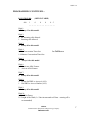
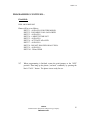
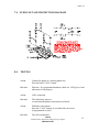
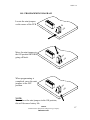
1
SSC-501-D OR BLC-501-D-ADASPK1.07UNVLr1-ISSUE4.0
SERVICE MANUAL
FOR
MODEL SSC-501-D
OR
MODEL BLC-501-D
STAINLESS STEEL HANDS FREE
AUTO-DIAL TELEPHONE
EQUIPPED WITH SPK1.07UNVLr1 FIRMWARE
Serving the Telephone Industry Since 1930
Communication Equipment
& Engineering Company
519 W South Park Street
Okeechobee, FL 34972
Voice: 863-357-0798
Fax: 863-357-0006
ISSUE 4.0
IMPORTANT INFORMATION
FOR
CUSTOMER
Please fill in before you continue.
The following information is necessary when calling CEECO for assistance.
MODEL NUMBER
MODEL SSC-501-D-ADA OR BLC-501-DADA, EQUIPPED WITH SPK1.07UNVLr1
FIRMWARE.
SERIAL NUMBER
DATE MANUFACTURED
LOCATION INSTALLED
For us to better serve you, please have this information available when calling for
technical support.
CEECO
Communication Equipment & Engineering Company
519 W South Park Street
Okeechobee, FL 34972
863-357-0798- telephone
863-357-0006- facsimile
[email protected]
www.ceeco.net
CEECO
Communication Equipment & Engineering Company
PROPRIETARY
2
ISSUE 4.0
TABLE OF CONTENTS
SECTION
PAGE
1.0
INTRODUCTION................................................................................................. 4
2.0
GENERAL............................................................................................................. 4
3.0
PROGRAMMING ................................................................................................ 6
PROGRAMMING CONTINUED…................................................................... 7
PROGRAMMING CONTINUED…................................................................... 8
4.0
OPERATION ........................................................................................................ 9
5.0
RECOMMENDED TOOLS AND TEST EQUIPMENT .................................. 9
6.0
INSTALLATION NOTES AND ASSEMBLY INSTRUCTIONS ................. 10
7.0
OVER-VOLTAGE PROTECTION DIAGRAM............................................. 11
8.0
TESTING............................................................................................................. 11
9.0
SPECIFICATIONS............................................................................................. 12
10.0
PARTS LIST ...................................................................................................... 13
11.0
FCC NOTICE...................................................................................................... 14
12.0
REPAIR AND RETURN INFORMATION..................................................... 15
13.0
WARRANTY POLICY ...................................................................................... 16
14.0
PROGRAMMING DIAGRAM ......................................................................... 16
CEECO
Communication Equipment & Engineering Company
PROPRIETARY
3
ISSUE 4.0
1.0 INTRODUCTION
The practices in this manual provide installation and maintenance information for
the CEECO Model SSC-501-D-ADA OR BLC-501-D-ADA Telephone, equipped
with SPK1.07 UNVLr1 firmware.
The information in this manual is subject to change without notification.
For information not included in this manual, please call or write:
CEECO
Customer Service
519 W South Park Street
Okeechobee, FL 34972
863-357-0798- telephone
863-357-0006- facsimile
[email protected]
www.ceeco.net
2.0
GENERAL
2.1
The CEECO hands free telephone is a sturdy, vandal resistant, Stainless
Steel Panel Speakerphone. Instead of a hookswitch and handset, the
telephone has a Press to start/Press to stop button for initiation and
termination of phone calls. The Telephone may be programmed to
automatically dial a single number of up to eleven (11) digits in length. It
may also be programmed to dial a preceding PBX or other access number.
The telephone provides visual indication of call progress by way of a
changing color LED. Manual volume control is also provided inside the
telephone.
2.2
The microphone is muted during periods of dial tone eliminating the use
of hand held dialers.
2.3
Incoming calls may be allowed or blocked depending on the
programming.
2.4
Programming is accomplished via the DTMF keypad, inside the housing.
CEECO
Communication Equipment & Engineering Company
PROPRIETARY
4
ISSUE 4.0
CEECO
Communication Equipment & Engineering Company
PROPRIETARY
5
ISSUE 4.0
3.0
PROGRAMMING
NOTE:
It is recommended that you ground yourself to prevent ESD
damage to the PCB(s).
3.1
Connect the phone to a working telephone line or a DTMF test set before
programming.
3.2
Move the mini-jumpers (located on the CEECO-SPK Printed Circuit
Board) to the “ON” position, as depicted on the last page of this manual.
3.3
Press the CALL button and wait for dial tone before programming any
digits.
3.4
Each location is accessed by dialing the "#" sign and a two digit code. The
valid program locations are: #00, #30-#69 (speed dial locations), and #70#89 (allowed call locations). The previous contents of the location are
automatically erased when the location code is accessed.
NOTE: Once the “#" (pound) key has been entered you may get an
operator recording or a fast busy, please disregard and continue
programming.
3.5
To clear all user programmable memory, with the phone on hook (no dial
tone) and the mini-jumpers in the "ON" position, press the CALL button
located on the front of the phone and dial #97.
3.6
Location "00" is the phone option location. It is comprised of ten digits,
all of which must be filled to render the phone functional. By entering 0
or 1 into each of the 10 digits (digits 4 and 10 allow choices of 1-9 to be
entered), the phone is customized to a particular installation. Be sure to
record your entries in the option table for future reference.
CEECO
Communication Equipment & Engineering Company
PROPRIETARY
6
ISSUE 4.0
PROGRAMMING CONTINUED…
LOCATION #00:
#00
(OPTION TABLE)
1
0
0
0
0 5
__ __ __ __ __ __ __ __ __ __
Digit 1:
1 Always 1 for this model.
Digit 2:
0 No incoming calls allowed.
1 Incoming calls allowed.
Digit 3:
0 Always 0 for this model.
Digit 4:
0 No Conversation Time-Out.
1-9 Minutes Conversation Time-Out.
For Call Button
Digit 5:
0 Always 0 for this model.
Digit 6:
0 Deactivate ADA Feature.
1 Activate ADA Feature.
Digit 7:
0 Always 0 for this model.
Digit 8:
0 Do not dial PBX or Access # (#18).
1 Dial PBX or Access Number (#18).
Digit 9:
0 Always 0 for this model.
Digit 10:
0 No Wink Detect
l-9 Length of the Wink (l = 50ms incremental to 450ms – entering a 5 is
recommended)
CEECO
Communication Equipment & Engineering Company
PROPRIETARY
7
ISSUE 4.0
PROGRAMMING CONTINUED…
EXAMPLE:
DIAL #00 0106011005
Phone will be set as follows:
DIGIT 1 .. ALWAYS O FOR THIS MODEL.
DIGIT 2 .. INCOMING CALLS ALLOWED
DIGIT 3 .. ALWAYS 0
DIGIT 4 .. 6 MINUTE TIME OUT
DIGIT 5 .. ALWAYS 0
DIGIT 6 .. ACTIVATE ADA LED
DIGIT 7 .. ALWAYS 0
DIGIT 8 .. DO NOT DIAL PBX OR ACCESS #
DIGIT 9 .. ALWAYS 0
DIGIT 10 . 250ms WINK
3.7
When programming is finished, return the mini-jumpers to the "OFF"
position. Then hang up the phone (“on hook” condition), by pressing the
black "CALL " button. The phone is now ready for use.
CEECO
Communication Equipment & Engineering Company
PROPRIETARY
8
ISSUE 4.0
4.0
OPERATION
4.1
To make a call, press the black "CALL" button located on the front of the
phone. When dial tone is received, the transmitter is muted and the phone
waits for numbers to be dialed. The Telephone will automatically dial the
preprogrammed number(s).
4.2
After the call is complete, press the "CALL" button again to terminate the
call. If user does not press the "CALL" button when he or she is finished
using the phone, then the phone will hang-up after detecting a WINK
(momentary open) or when the timer times-out, if it was so programmed.
NOTE: In some cases, a local PBX does not automatically send a wink
back as a Central Office would. Some of these PBXs can be
programmed to do so. It would be necessary to contact the
manufacturer of the PBX.
4.3
5.0
A visual indication of the call progress is given through the changing color
LED located on the front of the housing. The LED lights red when the
phone is on. It flashes red and green during ringing and turns GREEN
when answered.
RECOMMENDED TOOLS AND TEST EQUIPMENT
DTMF Test Set
Volt/Ohm Meter
3/8" Nut Driver
5/16" Nut Driver
Flat Blade Screw Driver
Security Tool, CEECO Part Number 301-064
CEECO
Communication Equipment & Engineering Company
PROPRIETARY
9
ISSUE 4.0
6.0
INSTALLATION NOTES AND ASSEMBLY INSTRUCTIONS
6.1
Using a 301-064 security tool (sold separately) to remove the four locking
screws.
6.2
The security tool is for a standard 5/32" button head screw generally used
on the framework of the phone booths.
6.3
Separate the cover assembly from the Housing.
6.4
Run the inside station wire through the Housing and terminate on to the
RJ11C modular jack on the housing, as depicted on the following page.
This CEECO-provided modular jack must be used, as it contains required
over-voltage protection.
6.5
The use of a gas tube or carbon station protector is recommended. The
station ground should not exceed 50 ohms.
6.6
Plug the modular line cord from the PC board into the RJ11C terminal
block.
6.7
Dress the line cord away from the locking screws and seat the faceplate
into the enclosure.
6.8
Secure the cover assembly by tightening the security screw.
*****WARNING*****
A.
Never install telephone wiring during a lightning storm.
B.
Never install telephone jacks in wet locations unless the jack is
specifically designed for wet locations.
C.
Never touch uninsultated telephone wires or terminals unless
the telephone line has been disconnected at the network
interface.
D.
Use caution when installing or modifying telephone lines.
CEECO
Communication Equipment & Engineering Company
PROPRIETARY
10
ISSUE 4.0
7.0
8.0
OVER-VOLTAGE PROTECTION DIAGRAM
TESTING
Action:
Connect the phone to a working phone line.
Press the black "CALL" button.
Reaction:
Dial tone. Pre-programmed number(s) dials out. LED gives visual
indication of call progress.
Action:
Call is connected.
Reaction:
The called party answers.
A normal speakerphone conversation is allowed.
Action:
Finish the conversation.
Press the "CALL" button, or wait until time-out occurs
(if programmed as such).
Reaction:
The call is terminated.
CEECO
Communication Equipment & Engineering Company
PROPRIETARY
11
ISSUE 4.0
9.0
SPECIFICATIONS
INPUT POWER:
C.O. Line powered
LOOP CURRENT:
33mA minimum 80mA Maximum
IMPEDANCE:
600 ohms
SIGNALING:
DTMF
OUTPUT:
-2.0dbm to -0dbm
ENVIRONMENTAL:
Temperature 0oC to 50oC
Humidity
20%-90%
TELEPHONE PANEL:
Stainless Steel (14ga)
DIMENSIONS:
7 1/2" Wide x 21" High x 4 1/8" Deep
MOUNTING:
Standard Coinless Public telephone foot
print
WEIGHT:
15 lb.
RINGER EQUIVALENCY:
0.4A
TYPE JACK:
RJ11C
UL LISTED NO.:
6OF5
CEECO
Communication Equipment & Engineering Company
PROPRIETARY
12
ISSUE 4.0
10.0
PARTS LIST
QUANTITY PART NUMBER
DESCRIPTION
1
301-030
INSTRUCTION CARD KIT
1
301-012
OUTER COVER LOCKING SCREW
1
301-018
MODULAR LINE CORD
1
SSC-501-D (or)
BLC-501-D
STAINLESS STEEL OUTER COVER
BLUE POWDER COAT STEEL COVER
1
301-039
NUMBER WINDOW
1
301-040
NUMBER CARD
1
301-051
BACK PLATE
1
301-052
RUBBER GROMMET
1
301-054
MODULAR CONNECTOR (RJ11C)
1
391-017
KEYPAD CABLE
1
600-SPK
CIRCUIT BOARD WITH MICROPHONE
1
14123
SPEAKER
1
705-110
CONNECTORIZED KEYPAD
1
951-001
MOMENTARY PANEL SWITCH
2
321-016
SECURITY SCREW
301-064
SECURITY TOOL
ACCESSORIES
1
CEECO
Communication Equipment & Engineering Company
PROPRIETARY
13
ISSUE 4.0
11.0 FCC NOTICE
11.1
FCC REGISTRATION AND REPAIR INFORMATION
Your new telephone has been registered with the Federal Communication
Commission (FCC) in accordance with Part 68 of its rules. The FCC
requires that you be advised of certain requirements involving the use of
this telephone.
11.2
CONNECTION WITH THE NATIONWIDE TELEPHONE
NETWORK
The FCC requires that you connect this telephone to the Nationwide
Telephone Network through a registered jack provided by the Telephone
Company in your area. This jack is a modular outlet, which you can order
from your local telephone company.
11.3
NOTIFICATION TO THE TELEPHONE COMPANY
Before connecting this telephone, the FCC requires that you notify your
local telephone company business office. The number is in the front of
your phone book.
Tell them:
The "line" to which you will connect the telephone (that is, your phone
number) and the telephone's FCC registration number and ringer
equivalence number. These numbers are listed in Section 11.00.
The FCC further requires that you notify your local telephone company
when permanently disconnecting this telephone.
CEECO
Communication Equipment & Engineering Company
PROPRIETARY
14
ISSUE 4.0
12.0 REPAIR AND RETURN INFORMATION
12.1
WARRANTY REPAIR
Any device returned requiring warranty service; repair or credit must be
accompanied with a "Return Material Authorization" (RMA) FORM. It must
include return shipping instructions, original purchase order number and special
marking instruction. A description of the trouble observed must be attached to the
defective unit. This information must be inside the shipping container.
12.2
DIRECT ALL INQUIRES TO:
CEECO
Repair Department
863-357-0798- telephone
863-357-0006- facsimile
[email protected]
www.ceeco.net
12.3
NON-WARRANTY REPAIR
CEECO will repair equipment out of warranty for a set charge plus parts.
The customer must pay the shipping costs both directions.
12.4
RETURN FOR CREDIT
Material may be returned for credit only with prior approval. Material
authorized for return is subject to a 20% restocking charge based on the
manufacturer’s list price Return RMA must be requested no later than 30
days after original shipment.
CEECO
Communication Equipment & Engineering Company
PROPRIETARY
15
ISSUE 4.0
13.0 WARRANTY POLICY
13.1
GENERAL
CEECO products are guaranteed to be free of defects in material and
workmanship for a period of 365 days from the date of original purchase.
CEECO's obligation under this warranty is limited to repair or
replacement of any part found to be defective by CEECO. Under no
circumstances shall CEECO be liable for loss, damage, cost of repair or
consequential damages of any kind, which have been caused by neglect,
abuse, act of God or improper operation of equipment. This warranty is
limited to the value of material only.
13.2
PRINTED CIRCUIT BOARDS
Printed circuit boards should not be repaired in the field. If a unit is found
to be faulty, replace it with another unit and return the faulty unit to
CEECO for repair. Modifications by any one other than CEECO will void
the warranty.
CEECO
Communication Equipment & Engineering Company
PROPRIETARY
16
ISSUE 4.0
14.0 PROGRAMMING DIAGRAM
Locate the mini jumpers
on the corner of the PCB.
ON
F
OF
Move the mini jumpers to
the ON position BEFORE
going off-hook.
When programming is
completed, move the mini
jumpers to the OFF
position.
ON
F
OF
ON
F
OF
NOTE:
Do not leave the mini jumpers in the ON position,
this will decrease battery life.
CEECO
Communication Equipment & Engineering Company
PROPRIETARY
17
ISSUE 4.0
CEECO
Communication Equipment & Engineering Company
PROPRIETARY
18