1
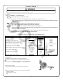
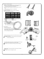
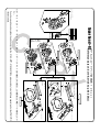
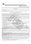
Kit Instruction Manual
CO
Item No.:01−03−8201BG
Applicable models and frame Nos
Monkey :Z50J-2000001∼
CRF50F :AE03-1400001 ∼
:AB27-1000001 ∼
XR50R :AE03-1000001 ∼
Gorilla :Z50J-2500001∼
:AB27-1000001 ∼
・Thank you for purchasing one of our TAKEGAWA's products. Please strictly follow the following instructions in installing and using the products.
・Before fitting the products, please be sure to check the contents of the kit. Should you have any questions about the products, please kindly contact your
dealer.
∼ Features ∼
○ As both the single CDI unit and twin ignition coil are used, a sub-plug has been added to the existing Super Head +R. Thus, this kit helps to burn the unburned gas at the opposite side of the original plug. With this kit, almost complete combustion can be realized and the engine can be more powerful at
any level of revolutions. Especially, power characteristics at high-rotary area has improved.
○ This kit is a special model of Super Head+R with a barrel-polishing processed cylinder head and with a gold and black alumite-treated side cover, thus
making the appearance much more noticeable.
Safety Precautions for Use
〇 This kit is for exclusive use in motorcycles with 12v stock ignition system and stock electric components. This kit is installable onto bikes with a TAKEGAWA-made hyper-CDI as well. Please note, however, that this kit is not installable onto bikes working on 6v, or with inner rotor CDI, or with an ignition system of other manufacturers’.
〇This cylinder head kit is for exclusive use with an engine equipped with our TAKEGAWA-made Bore Up Kit or Bore Stroke Up Kit. Therefore, please never
use this kit in combination with any other parts of any other manufacuturers’.
〇 This kit cannot be used in a bike equipped with a stock muffler, up-type muffler, or right-pointing carburetor.
〇Please be informed that the Twin Spark Head Piston isn't compatible with a conventional Super Head+R Piston.
〇Please never apply liquid packing or the like to the provided metallic cylinder head gasket. Install it just as it is.
〇A sub plug comes with this kit, but a main spark plug isn’t included with this kit. So, please purchase an extra-cost main spark plug of heat value to meet
the engine specifications.
○ Installation of this kit requires processing of a crankcase. As the crankcase is bored, the durability of the crankcase will decrease, consequently leading
to damages of the crankcase in some cases, which please note.
PY
Safety precautions to observe when using the tachometer:
The tachometers which can be used with this Twin Spark Super Head are
as per the list on the right. Any other electric tachometers won’t operate
properly.
Fitting tachometers:
・Super Multi LCD Meter ・LCD Speedo- & Tacho-meter Kit
・Large LCD Speedo- & Tacho-meter
・Medium LCD tachometer
:009-01-0901
:009-01-331
:009-01-332
:009-01-0042
:009-05-0141
Please read the following carefully before starting installation
◎ We do not take any responsibility for any accident or damage whatsoever arising from the use of the products not in conformity with the instructions in
the manual.
◎This kit is designed for exclusive use in the above-mentioned applicable models of motorcycles and frame numbers, and for exclusive use in motorcycles
equipped with a bore-up and bore-stroke exclusively for this kit as well. Therefore, please take note that this kit cannot be mounted on other applicable
models of motorcycles, or motorcycles not equipped with bore-up, etc exclusively for this kit.
◎Installation of this product requires removal and reinstallation of an engine, and disassembly of a clutch. Please prepare HONDA’s genuine service manual
for the above-mentioned applicable models, and work with enough care following instructions in the service manual. Besides, this instruction manual, as
well as HONDA’s service manual, is prepared for those who have acquired basic skill and knowledge in tuning. We recommend those who are technically
inexperienced or without right tools to ask a technically-trustworthy specialist shop to do the work.
◎ We shall be held free from any responsibility or compensation whatsoever for any glitch in the parts other than ours if the glitch takes place after the installation and use of the products.
◎ If you make alterations to the products, we shall be held free from any guarantee of the products.
◎ You are kindly requested not to contact us about the combination of our products with other manufacturers'.
◎ A serial number is engraved on the cylinder head. You may be requested to inform us of the number when ordering parts.
◎ Bolts, and nats will be reused. However, be sure to replace worn-down or severely-damaged ones with new ones.
◎ Never use liquid packing. It may plug the oil passage, and in the worst case break the engine.
◎ Be sure to always use premium unleaded petrol. And make sure to check what kind of gasoline is remaining in the fuel tank. Whenever regular gasoline
is left in the fuel tank, always replace it with high-octane gasoline.
◎ Determine the heat value of a spark plug depending on how much it is burnt. In vehicles originally with a resistor plug, use a resistor plug.
◎ Never use this kit on the point-ignition system motorcycle.
◎Please be informed that what we can safely say is that the ignition system of this kit is compatible with ours and stock ignition systems, because no data
is available with us on the compatibility with other ignition systems. Therefore, please never use other ignition systems, which may cause technical troubles.
◎ As the stock clutch cannot be used, a centrifugal filter gets unavailable. Therefore, install an oil filter outside.
◎ Please install an oil cooler when necessary.
◎ Engine oil must be API SF or higher class, such as SAE 10W-40 / 15W-50, which are our recommendations.
◎ Upper limit of the engine revolutions is 12,000 rpm. Please install a revolution counter to always keep the revolutions below the upper limit.
◎ Change the sprocket with the one which meets the output and specifications.
◎ This kit cannot be used alone if you have purchased a cylinder head kit. If you have not purchased ”our special engine parts”, please purchase special
parts with reference to the attached ”Reference data on bore- & stroke-up kit.”
◎ This kit is compatible with only those engine parts recommended by us. So, please replace the engine parts not recommended by us with those of our
recommendations.
◎ Since this kit is designed and developed for driving in closed races, do not use the kit for running on public roads.
Jump-Starting and Sudden Acceleration
Idling, sudden acceleration, and sudden engine braking will put a heavy load on the engine, which please note may result in crank shaft damage and
engine breakage in the worst case.
- A’1 -
Oct./26/’
06
The following show the envisioned possibility of injuries to human bodies or property damages as a result of disregarding the following
Caution cautions.
・Since this kit is designed and developed for driving in closed races, do not use the kit for running on public roads.
・Work only when the engine and muffler are cool at below 35 degrees Celsius. Otherwise, you will burn yourself.
・Prepare right tools for the work. (Otherwise, improper work could cause breakage of parts or injuries to yourself.
・As some products and frames have sharp edges or protruding portions, please work with utmost care. (Otherwise, you will suffer injuries.)
・Always use new gasket and packing. (The worn or damaged parts may cause the engine troubles.)
CO
The following show the envisioned possibility of human death or serious injuries to human bodies as a result of disregarding the
Warning following cautions.
・Those who are technically unskilled or inexperienced are required not to do the work. (Improper installation because of insufficient skill and knowledge could lead to parts breakage and subsequently to accidents.)
・Before doing work, secure the motorcycle on level ground for safety's sake. (Otherwise, your motorcycle could overturn and injure you while you
are working.)
・Always start the engine in a well-ventilated place, and do not turn the engine on in an airtight place. (Otherwise, you will suffer from carbon monoxide poisoning.)
・As gasoline is highly flammable, never place it close to fire. Make sure that nothing flammable is near the gasoline. (It may cause a fire.)
・Always use a torque wrench to screw bolts and nuts tight and securely to the specified torque. (Improper torque could cause these parts to get
damaged or fall off.)
・Never use the parts unspecified by us. (This may lead to parts breakage and consequent accidents.)
・If you find damaged parts when checking and performing maintenance, do not use these parts any longer, and replace them with new ones. The
continued use of these damaged parts as they are could lead to accidents.)
・When you notice something abnormal with your motorcycle while riding down a road, stop riding immediately and park your motorcyle in a safe place. (Otherwise, the abnormaility could lead to an accident.)
・Before riding, always check every section for slack in parts like screws. If you find slack ones, screw them securely up to the specified torque.
(Or improper torque may cause parts to come off.)
・Check or perform maintenance of parts correctly according to the procedures in the instruction manual or a service manual. (Improper checking or
maintenance could lead to an accident.)
・Always use high-octane gasoline. (Otherwise, troubles such as engine knocking may cause accidents.)
PY
◎ Please be informed that, mainly because of improvement in performance, design changes, and cost increase, the product specifications and prices
are subject to change without prior notice.
◎ This manual should be retained for future reference.
●Cautions before riding:
● About camshaft:
① About fuel:
Whenever regular gasoline is remaining in the fuel tank, always replace it
with high-octane gasoline.
②With this kit installation, a centrifugal filter will be lost. So, please install a dry-type clutch with an external oil filter or a special clutch.
③ About change of a sprocket:
◇The installation of this kit will increase the power of your vehicle. So the use of a stock sprocket will result in severe wears of parts because of too
low gear, not only adversely affecting the engine life, but also breaking the
engine in the worst case. Therefore, please change the sprockets with the high-geared one.
This kit cannot function on its own. Referring to the
attached sheet, please purchase a bore-stroke-up
kit for exclusive use with this kit. This does not apply if you have purchaed a full kit.)
● Others:
Oil cooler:
◇ The installaiton of this kit increases the heat release value of the engine,
set off by the increase in power. For a long-time and high load running, we
recommend you to install an oil cooler kit which keeps oil at appropriate temperatures and prevents such troubles as oil film shortage at high
temperatures.
Carburetor manifold:
◇ On a manifold, compatible with R-Stage & Super Head, with a port
diameter of φ24∼φ25 on the side of an inlet pipe, there will be bumps because of the difference in diameter between the cylinder head and the
manifold. Enlarging the manifold's port diameter on the manifold side will provide you with smoother output characteristics.
φ25→φ26
● An inspection cap and a breather cap are included in this kit. In case you
use a breather cap, please use an oil catch tank at the same time.
●Revolution
◇Upper limt of revolutions varies depending on the installed cam shafts, etc.
Referring to the camshaft comparison graph on page 3, install a revolution
counter to make sure that you drive the engine at revolutions below the upper limit.
◇Take note that idling and sudden acceleration in the 1st and the 2nd gears
particularly tend to exceed the upper limit of revultions. Over revolutions will result in nonsmooth revolutions of the engine, not only adversely affecting the engine life, but also breaking the engine in the worst case.
●Valve spring retainer
◇This Super Head includes a titanium valve spring retainer as a stock equipment. We have succeeded in developing and making this titanium valve spring retainer lighter than a steel retainer by about 30 percent. Besides, we have treated the surface with S-PVD coating which has surface hardness of over HV2300. This S-PVD coating excels
conventional tin coating in shock and wear resistance. However, its durability is inferior to that of the steel retainer. So check and perform maintainance periodically for damage and wear. Always replace a
damaged or worn retainer with a new one. We would recommend those
who attach importance to durability to equip a steel valve spring retainer.
HONDA offers a valve spring retainer (Item No. 14771-MR8-000)
compatible with this kit.
1
5
2
φ
∼
4
2
φ
◇If you have purchased a cylinder head kit, a special camshaft is needed separately. Camshafts with a few kinds of profiles are available from us to
meet different uses and engine displacement. Even if you have purchased
a full kit, you can study to use them as an optional extra in addition to camshafts inclued in the full kit. For more information, please refer to enclosed paper.
6
φ2
- A’2 -
Oct./26/’
06
●A serial number is punched on the cylinder head just for the sake of administration. You may be requested to inform us of the number when ordering repair parts.
In case you are not able to order parts because you do not have the repair parts numbers or for other
reasons, please place an order in the following way.
☆ Make a note of the number punched on the left side of the cylinder head.
A head No. (2SM-000***)is punched here.
Head No. - 2SM-000001
Example of how to order → Super head kit, repair
head No.-2SM-000001 → Intake valve Qty: 1 piece
● For those who have purchased a cylinder head alone, selection sets are available to meet your combination demand for engine displacement, etc. Please study the required contents of the kit, referring to ”Reference data on bore & stroke-up kit” on enclosed paper.
Please contact your dealer for more details about the kit or enquiries.
CO
2SM-000000
A head No.
(2SM-000***)
is punched here
●Engine parts of our recommendations:
※ This kit is only compatible with those engine parts recommended by us. So, please replace the parts not of our recommendations with those of our recommendations.
Parts of our recommendations
Special clutch kit
Dry-type clutch kit
Stock C.D.I.
Clutch
Ignition system
Hyper C.D.I.
C.D.I. magnet
07-02-15
05-02-052
MONKEY 03-05-0981
Keihin PE28 carburetor kit
MONKEY-R 03-05-095
MONKEY
Carburetor
03-05-0484
MONKEY-R
Mikuni VM26 carburetor kit
CRF50F
03-05-3245
XR50R
Oil pump
Super oil pump kit
01-16-0051
124cc
01-14-003
Cam chain(Only in case of a cylinder head kit) High-duty cam chain kit Oil catch tank
Only for the Monkey/Gorilla
09-04-031
(Only in case a head breather cap is used.)
09-04-032
● About optional camshafts
PY
○ The following camshafts compatible with this kit are available from us.
Referring to the list on the right, please select a camshaft to match your usage and engine displacement to enjoy a ride.
S-12
S-15
S-20
S-25
S-30
S-35
camshaft
camshaft
camshaft
camshaft
camshaft
camshaft
01-08-0012
01-08-0015
01-08-0020
01-08-0025
01-08-0030
01-08-0035
option
option
(Included for bore stroke-up for the Moneky / Gorilla(124)
option
option
option
○ Part of the model names of our camshafts are indicated in numbers. To cite an example, the larger the number in S- ○○ , the wider the camshaft profile
operating angle. And the smaller the number, the narrower the profile operating angle. In general, the wide-angle profile is a high-speed rotation type, and
the narrow-angle profile is a slow-speed rotation type.
However, various factors like the engine displacement, specifications, usage, etc have to be taken into account in selecting the camprofile. So, referring
to the list just as a guideline, select an appropriate camshaft to meet the usage.
☆Camshaft comparison data list
Note: As these are the data measured on a Dyno Jet, the data differ from the actual driving. Please refer to them just for a reference. The engine power varies significantly depending on the temperatures.
● 124 cc
Test Vehicle : MONKEY 54X54 124 cc Carburetor : KEIHIN PE28 Exhaust : Racing Muffler
Test Vehicle : MONKEY 54X54 124 cc Carburetor : KEIHIN PE28 Exhaust : Racing Muffler
20
18
16
SAE Power(PS)
SAE Power(PS)
20
30 cam
18
16
25 cam
20 cam
15 cam
14
14
12 cam
12
12
10
10
8
8
6
6
4
4
2
35 cam
2
RPM(×1000)
RPM(×1000)
0
0
3
4
5
30 cam
6
7
8
9
20 cam
10
11
12
13
14
15
3
4
5
35 cam
12 cam
- A’3 -
6
7
8
25 cam
9
10
11
12
13
14
15 cam
Oct./26/’
06
∼ Kit Contents ∼
18
18
18
18
10
14
11
CO
1
G
E
C
9
16
16
15
26
13
19
3
H
F
D
23
B
22
23
2
22
21
23
23
A
24
2
22
I
C
000―03―050
J
K
E
D
F
H
G
32
29
36
35
31
7
13
PY
4
10
16
6
33
12
25
5
6
33
16
17
8
18
20
30
18
27
17
34
28
∴ Please order repair parts by indicating the numbers listed below. In some cases, we may not be able to accept your orders for a component of the assembled unit. In this case, please order the required parts in units of sets.
01―13―8004
000―03―070
000―03―069
9
13
10
13
No.
1
2
3
4
5
6
7
8
9
10
11
12
13
14
15
16
17
18
19
20
21
000―03―059
16
000―03―060
18
16
18
000―03―094
17
18
16
18
16
Inspection cap screw set Right side-cover screw set
Parts Name
Cylinder head COMP.
Rocker arm COMP.
Rocker arm shaft
Cam sprocket
Cam gear washer
Cap screw M5x12
Cam shaft circlip
Left side-cover
Breather cap
Inspection cap
Right side-cover
Left side-cover O-ring
Inspection cap O-ring
O-ring S15
Right side-cover O-ring
Cap screw M5x15 (SUS)
Cap screw M5x20 (SUS)
Cap screw M5x12 (SUS)
Manifold gasket
Exhaust pipe gasket
Copper sealing washer
Qty
1
2
1
1
1
2
1
1
1
2
1
1
2
1
1
4
2
6
1
1
1
Repair parts No.
※
14431-SPH-T00
14451-SPR-T00
000-08-003
000-03-059 (SET)
Qty
1
1
1
1
1
2
3
1
1
1
1
3
3
6
3
4
000-03-060 (SET)
03-005-0256 (SET)
000-13-046 (SET)
000-03-052 (SET)
4
3
2
2
Symbol
Parts Name
A
Intake valve
B
Exhaust valve
C Valve spring outer seat
D Valve stem seal
E
Valve spring (outer)
F
Valve spring (inner)
Qty
1
1
2
2
2
2
Repair parts No.
14711-SPH-T00
14721-SPH-T00
000-03-055 (SET)
000-03-064 (SET)
Qty
1
1
2
2
2
2
000-03-063 (SET)
000-08-010 (SET)
※
000-03-069 (SET)
000-03-070 (SET)
11121-SPH-T01
01-13-8004 (SET)
01-12-0101 (SET)
17
18
18
Left side-cover screw set
No.
22
23
24
25
26
27
28
29
30
31
32
33
34
35
36
Parts Name
Sealing washer
Cap nut M6
Cap screw M6x18
Dowel pin, 8x12
Socket set screw M6x15
Spark plug sleeve
Spark plug NGK ER8EH
Spark plug cap
Ignition coil COMP.
Ignition coil stay COMP.
Ignition coil sub-cord
Dowel pin, 7x10
Plug-sleeve O-ring
Flange bolt 5x10
Flange bolt 5x22
Insulation lock, 100mm
Insulation lock, 150mm
Aluminum Special (5g)
Tool Hex wrench 3 mm
Tool Hex wrench 4 mm
Tool Hex wrench 5 mm
Qty
3
4
1
1
2
1
1
1
1
1
1
2
1
1
1
1
2
1
1
1
1
Symbol
Parts Name
G
Valve spring retainer
H
Valve cotter
I
Radial ball bearing
J
C-shaped ring
K
Stud bolt 6x32
Qty
2
4
1
1
2
Repair parts No.
Qty
BW-00-0008 (SET)
000-02-0002 (SET)
000-03-062 (SET)
※
4
3
2
1
000-03-018
000-03-017
000-03-016
000-03-015
000-03-095 (SET)
000-03-075 (SET)
1
1
1
1
2
3
00-01-0001
1
Repair parts No.
01-12-084 (SET)
000-03-056 (SET)
000-03-058 (SET)
000-03-057 (SET)
Qty
2
4
1
1
2
※The following components are not available as a single item for repairing purposes: barrel-polishing processed cylinder head COMP., colored alumite- treated left-side cover, and colored alumite-treated spark plug cap.
If you are in need of these parts, please purchase a non-barrel-finishied stock components instead: cylinder head COMP of SP/H-2SM-T100, left-side cover of 1341-SPH-T01, and spark plug cap of 12351-SPH-T00.
3-5-16 Nishikiorihigashi Tondabayashi Osaka Japan
- A’4 -
TEL : 81-721-25-1357 FAX : 81-721-24-5059 URL : http://www.takegawa.co.jp
Oct./26/’
06
∼ Cylender Head Installation Procedures ∼
○ Removethe rocker arm shaft and
adjusting bolts and nuts on the original cylinder head.
○ Thoroughly degrease the upper surface of the cylinder.
○Fix the cam chain so it will not fall into the crankcase.
○In the case of a V, H or S (for SCUT)
cylinder, attach a cylinder head
gasket.
CO
the specified torque.
T : 10N・m (1.0kgf・m)
○ Apply engine oil to the bearings
of the cam shaft of the kit, and install it to the cylinder head.
Then fix 8x12 dowel pins into the
NEW
○ Apply engine oil to the removed
adjusting bolts, and fixthese bolts
to rocker arms of the kit.
OIL
Note: These cylinders have a marking
on the cylinder head surface or
its Item No. is stamped on the fin side.
Item No.
stamped
here
○ Fix the rocker arms to the Super
Head.
Apply molybdenum solution to the
original rocker arm shaft, and fix it
on the exhaust side.
Apply molybdenum solution to a
rocker arm shaft of the kit as well,
and fix it with its slit part pointing
to the cam chain side.
MO-OIL
○ After applying Aluminum Special a
little to the threaded part of the
cylinder head stud bolts, fix a
copper washer of the kit to the lower-left part (oil line) and
center hole of the cam shaft.
washers of the kit to other parts. Then fix four cap nuts of the kit and
M6x18 cap screws as indicated in
the figure below, and loosely tighten
them.
PY
Copper sealing
washer
Marking
Cap screw
Item No.
stamped here
○ Tighten a cam chain guide roller
of the cylinder to the specified torque.
CAUTION : Be sure to tighten to Marking
○ In the case of a cylinder with no Item No. or stamped marking or a
supplied cylinder coming with a green rubber gasket, attach a
cylinder head gasket, black rubber
packing and green rubber gasket.
○ Tighten nuts on the stud bolt
diagonally to the specified torque in
a few steps.
CAUTION : Be sure to tighten to the
○ Fix a cam shaft circlip of the kit,
and fix the cam shaft.
At this stage, set the location of
ring end gap of the circlip not to meet the notch on the cylinder head
cam hole.
specified torque.
T : 12N・m (1.2kgf・m)
NEW
Notch
○Remove the side bolt on the cam
chain tensioner.
○ Set the piston at the top dead
MO-OIL
Included part for intake side
○Fix 8x14 dowel pins of the kit into
center position, and install the
cylinder head.
○Tighten the side bolt on the cylinder
side and the cap screws on the
cylinder head side to the specified
torque.
CAUTION : Be sure to tighten to the
specified torque.
T : 12N・m (1.2kgf・m)
the dowel pin holes on the
cylinder.
- B’1 -
Oct./26/’
06
○ Attach the cam chain to the cam
○ Apply engine oil a little to two kinds
sprocket, and fix them with a cam
sprocket plate and two M5x12 (black) cap screws included in the
kit.
(At this point, apply Aluminum
Special a little to the threaded parts of the cap screws.)
Then align the “T” mark on the
of O-rings for the right side cover,
and fix them to the right side cover.
Then tighten them with M5x12 cap
screws of the kit to the specified torque.
CAUTION: Be sure to tighten to the
specified torque.
T : 6N・m (0.6kgf・m)
CO
flywheel with the alignment mark
on the crank case, and align an “O” mark on the cam sprocket with
the alignment mark on the
cylinder head.
NEW
○Apply engine oil a little to a left-side cover O-ring of the kit, and fix it to the left side cover. Then fix them to
the cylinder head with two M5x12
cap screws and with two M5x20 cap screw of the kit and tighten them
to the specified torque. (Be careful
of the location of screws.)
CAUTION: Screws must be used at the specified positions only.
CAUTION: Be sure to tighten to the
specified torque.
T : 6N・m (0.6kgf・m)
Marks
mark on the cam sprocket.
specified torque.
T : 10N・m (1.0kgf・m)
hole in the cam chain tensioner,
and tighten the side bolt.
CAUTION: Be sure to tighten to the
specified torque.
T : 8N・m (0.8kgf・m)
○ With reference to the service manual, mount the engine on the
frame.
CAUTION: Be sure to follow the
instructions in the manual.
○ Install socket cap screws of the
kit to two taps on the cylinder head
ports which will not be used for
manifold installation, and tighten them to the specified torque.
CAUTION: Be sure to tighten to the
specified torque.
PY
○Check that the “T” mark on the
flywheel is still aligned with the “O”
○Holding the crank, tighten the cap
screws, which are attached to fix
the cam sprocket, to the specified
torque.
CAUTION: Be sure to tighten to the
M5X20
M5X20
○Pour engine oil from the side bolt
○ Adjust the valve clearance with the
adjusting screw.
Intake:0.08(when cold) ± 0.03
Exhaust:0.10 (when cold) ± 0.03
○Tighten the adjusting nut to the specified torque.
CAUTION: Be sure to tighten to the
specified torque.
T : 10N・m (1.0kgf・m)
M5X12
M5X12
○After applying engine oil a little to an
O-ring on the inspection cap of the
kit, attach the O-ring to the
inspection cap, and fix the
inspection cap with M5x15 cap screw of the kit, and tighten up the
screw to the specified torque.
● In case a breather cap is used:
○ Apply engine oil a little to insection
cap O-rings of the kit, and fix them
to the breather cap and the
inspection cap. Then fix and tighten
the breather cap on the intake side
and the inspection cap on the
exhaust side with M5x15 cap screws of the kit to the specified torque.
CAUTION: Be sure to tighten to the
specified torque.
T : 6N・m (0.6kgf・m)
T : 5N・m (0.5kgf・m)
These taps will
not be used.
○ Following the instruction manual
for the relative carburetor, install
the carburetor.
○ Install the drive sprocket.
CAUTION: Be sure to tighten to the
specified torque.
T : 12N・m (1.2kgf・m)
NEW
- B’2 -
Oct./26/’
06
○ Install the generator cover.
○ Fasten the provided ignition coil CAUTION: Be sure to tighten to the
specified torque.
T : 7 ∼ 11N・m
(0.7 ∼ 1.1kgf・m)
above the detached ignition coil, and
○ Check that the ignition key and the
fasten the detached ignition coil
below the provided ignition coil, with fuel cock are turned OFF.
○Continue kicking the starter for a a 5x22 flange bolt which please while to circulate the engine oil all tighten to the specified torque.
around the engine.
T : 8N・m (0.8kgf・m)
○ Install the spark plug at the original
※ If the space between the upper
lace.
ignition coil and fuel tank is small, Apply Aluminum Special a little to the
secure the sufficient space by
threaded part of the plug, and fix it.
bending the ignition coil stay.
CAUTION: Be sure to tighten to the
specified torque.
CO
○ Attach the O-ring to the spark plug
sleeve. Set the spark plug so the hex portion of the spark plug aligns
○Add engine oil in amount
specified by the clutch kit you use.
○ With reference to the service manual, attach the drive chain.
☆ In the case of a three-point support crank shaft (3B) kit, fix
a generator cover according
to crank-kit installation
instructions.
○ In case you use a breather cap,
fix a breather hose according to
oil-catch-tank installation
instructions.
∴ In case you use a breather cap,
fix a breather hose according to
oil-catch-tank installation
instructions.
・Item No. for a blade hose set
(1 m, with clips)
: 000-03-054
How to install an ignition
coil:
○ Separate a cord from the ignition
coil on the vehicle, and detach the
ignition coil from the frame.
Ignition coil
○Connect the sub-cord of the ignition
coil to both wire harness and
ignition coil.
※ Connect the coil-cord of the wire with the sleeves on the plug sleeve.
And lightly apply the Aluminum
Special to the threaded portion on
the plug. Slightly apply engine oil to
the O-ring, and screw in the plug sleeve to the side cover of the left
cylinder head. And tighten the plug
sleeve to the specified torque.
T : 10N・m (1.0kgf・m)
○Turn ON the fuel cock and ignition
key, and start the engine.
WARNING: Work only in a
well-ventilated place.
○ Check for any abnormality such
as an abnormal sound.
○ If nothing abnormal is detected,
carry out a shakedown for about
30 to 50 km, and check the valve
clearance again.
CAUTION: Work only when the
engine and the muffler
are cool.
○ Carry out a shakedown again for
about 100 to 150 km.
○ After the shakedown, double- check for any abnormality such
as an abnormal sound and blow by gas.
(If any abnormality is detected, disassemble the engine again and
check each section.)
WARNING: Never re-use parts which cannot be
re-used.
PY
harness from above the frame pipe.
Sub-cord
☆ Engine Starting ☆
※The spark plug may be twisted apart if tightened to the excessive
torque.
※ Install the plug sleeve plug by screwing in the plug pulling up the
sleeve, being careful that the plug is
right on the groove. And also be
careful that the O-ring does not get
jammed.
○Cut the high-tension cord of the just connected ignition coil to the proper
length, and screw in the spark plug
cap.
Fix the plug cap with a 100mm
insulation lock.
※Fix the plug cap so it is in the proper
position when it is installed onto the
spark plug.
※ Please cut off the excess portion of
the insulation lock.
Spark plug
Plug sleeve
○Fit the plug cap into the plug sleeve
until the cap comes to a halt.
○ Fix the ignition coil stay to the frame with a 5x10 flange bolt, and
tighten the bolt to the specified torque.
T : 8N・m (0.8kgf・m)
Insulation lock
Plug cap
○Attach the plug cap to the spark plug.
5x10 flange
bolt
Coil stay
○ Wipe off the dirt and dust on the engine.
- B’3 -
Oct./26/’
06
∼ Owner’s Manual ∼
WARNING
Since this cylinder head manual is prepared for those who have acquired basic skills and knowledge in tuning, those who are
technically unskilled or inexperienced are required not to do the work.
CO
○Torque unit
1 kgf・m = 9.80665 N・m (=newton meter)
MO-OIL
○This mark shows molybdenum solution.
This solution is a mixture of molybdenum grease and engine oil (in the ratio of 1:1).
∴Apply molybdenum solution or assembly paste to the portions where it is indicated that molybdenum solution
needs to be applied.
NEW
○This mark shows those parts to be replaced with every overhaul.
Do not fail to replace these parts every time they are overhauled.
AL-SPL
○This mark means Aluminum Special (heat-resistant lubricating agent).
・Aluminum Special = heat-resistant lubricating paste and grease which prevent galling from high temperatures
and heavy loading, and adhesion.
(Purpose: good for those parts which get hot like a spark plug and exhaust manifold. )
PY
☆Never apply this to any parts other than the specified parts.
Reference Value List for Cylinder Head Maintenance
Items
Standard
Valve clearance (intake)
0.05∼0.08mm (when cold)
(exhaust)
0.05∼0.08mm (when cold)
Cylinder head distortion
Inside diameter of valve rocker arm
10.000∼10.015mm
Outside diameter of rocker arm shaft (intake / exhaust)
9.978∼9.987mm
Clearance between a rocker arm and a shaft
0.013∼0.037mm
Inside diameter of valve guide (intake / exhaust)
4.500∼4.512mm
Outside diameter of valve stem (intake)
4.475∼4.490mm
(exhaust)
4.460∼4.475mm
Clearance between a valve stem and a guide (intake)
0.01∼0.037mm
(exhaust)
0.025∼0.052mm
Valve seat contact width (Intake)
0.8∼1.0mm
(Exhaust)
1.0∼1.2mm
Free length of valve spring (outer)
34.8mm
(inner)
30mm
Valve spring retainer (intake / exhaust)
Service Limit
0.05mm
10.05mm
9.92mm
0.10mm
4.42mm
4.40mm
1.5mm
1.7mm
33mm
28.5mm
coating peeling
Remarks
Replace
Replace
Replace
Replace
Replace the guide or the head
Replace
Replace
Modify or replace the head
Modify or replace the head
Replace
Replace
Replace Check once every 500km
○ Valve Overhaul
Compress the valve spring with a valve spring compressor.
CAUTION: Do not compress the valve spring more than necessary.
∴ Specialized Tools : Valve spring compressor
Item No. 000-01-07
Valve spring compressor set Item No. 000-01-1005
○ Remove the valve cotters.
If it is hard to remove them, use a magnet to remove the cotters.
○ Detach the valve spring compressor, and remove the following parts.
・Valve spring retainer
・Valve springs (inner / outer)
・Valve
- C’1 -
Oct./26/’
06
○ Check each valve for bending, baking, and damages.
Measure the surface of the exterior valve stem sliding over a guide with
a micrometer.
Service Limit Intake : 4.42 mm Exhaust : 4.40 mm
Replace bent, scrached or damaged valves with new ones.
CO
○ Inspection of Valve Spring Retainer
Check the valve-spring-retainer surface to touch the valve spring.
Replace it with a new one if its coating is peeled off or it is damaged.
Check the spring contact
surface.
○ Inspection of Valve Seat
・Remove carbon sediments in the combustion chamber of the cylinder head and in the valves.
・Dissolve red lead primer with oil or the like, and apply the dissolved red lead primer to the valve faces evenly.
・Strike the valves once and lightly with a valve punner to rotate them.
・Wipe off the red lead primer on the valve faces, and strike the valves once and lightly with the valve punner without rotating them, and inspect
the contact surfaces.
PY
・If there is a scratch on the valve seat, modify the seat.
・If the contact width is too wide, narrow, high or low, modify the seat.
・Ask a specialist shop in internal combustion for the modification work.
Scratch on
the seat
Slanted valve
Low contact
High contact
○ Inspection of Rocker Arm
・Check the rocker arms for scratches, damages and jamming.
・Measure the internal diameter of the rocker arms.
∴ If the internal diameter is more than 10.05, replace the rocker arm.
- C’2 -
Oct./26/’
06
○ Inspection of Rocker Arm Shaft
・Check the rocker arm shafts for bending, scratches, and damages.
・Measure the external diameters of the rocker arm shafts.
∴ If the diameter is less than 9.92, replace them.
・Measure the clearance between the rocker arms and the rocker arm shafts.
∴ If the clearance is more than 0.10, replace them.
CO
○ Inspection of Cam Shaft
・Check the cam shaft for scratches, cracks, and damages.
・Measure the height of each cam top.
Intake
below 28.8 below 28.8 below 29.0 below 29.1 below 29.43
below 29.43
Exhaust
below 28.8
below 28.8
below 28.8
below 28.8 below 29.03
below 29.03
Replace
Replace
Replace
Replace
Replace
Replace
○ Inspection of Valve Springs
・Check the valve springs for scratches and damages.
・Measure the free length of the valve springs.
∴ Outer : If shorter than 33, replace them.
Inner : If shorter than 28.5, replace them.
If shorter than 33,
replace valve springs.
・Check the bearings in the cam shaft.
Rotate the outer race of the bearings. If the outer race does not rotate smoothly or if it is rickety, replace the cam shaft.
PY
○ Valve Assembly
・Clean up the cylinder head.
・Fix valve spring seats and new valve stem seals.
・Apply molybdenum solution to the sliding surfaces of the valve stems,
and fit the valves into the valve guides, rotating valvles slowly with care not to damage the stem seals.
Valve
MO-OIL
Stem seal N E W
Spring seat
Valve spring inner
Valve spring outer
If shorter than 28.5,
replace valve springs.
Kind of camshafts
S-12 cam shaft
S-15 cam shaft
S-20 cam shaft
S-25 cam shaft
S-30 cam shaft
S-35 cam shaft
Valve
MO-OIL
Stem seal N E W
Spring seat
Valve spring inner
Valve spring outer
Valve spring retainer
Valve spring retainer
Valve cotter
Valve cotter
・Attach the valve springs, placing the ones with shorter pitch pointing to
the combustion chamber.
CAUTION: Be sure to place valve springs with shorter pitch to face the combustion chamber side.
Combustion
chamber
shorter
pitches
・Apply grease a little to valve cotters. And compressing the valve springs
with a valve spring compressor, attach the valve cotters.
CAUTION: Do not compress the valve spring more than necessary.
・Strike the tops of valve stems a few times so the valves and cotters fit together well.
CAUTION: Be careful not to damage the valves.
- C’3 -
Oct./26/’
06
01―03―8201
01―03―8201BG
camshaft
camshaft
camshaft
camshaft
camshaft
camshaft
01-08-0012
01-08-0015
01-08-0020
01-08-0025
01-08-0030
01-08-0035
der
4cylin
HA12
r
ylinde
124 c
reference data.
er
cylind
V124
Three-point supporting crank shaft-54mm stroke
3点支持クランクシャフト―54mmストローク
05―02―0011AL
54mmストローク
54mm stroke
01―10―0091T
01―14―003
01―10―0091
01―14―003
01―10―8042
If you have purchased a cylinder head kit only (Item No. 01-03-8201・01-03-8201BG), please study to install these special parts referring to this
さい。
☆01―03―8201・01―03―8201BGシリンダーヘッドキットのみで購入された場合、この参照表にて専用パーツを検討して下
01―04―8224V
PY
CO
01―10―8042T
ボア&ストロークアップ参照表(124cc)
01―04―8224H
01―04―8224
2B又は3Bクランク選択
Select a 2B or 3B crank
Super head +R 124cc
Repair
parts
bore- & stroke-up kit (124cc)
data on
Reference
S-12
S-15
S-20
S-25
S-30
S-35
カムを選択
Select a cam
シリンダー選択
Select a cylinder
Jul./24/’
06