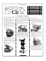
1
Instruction Manual for High-Compression Forged Piston Kit (φ67)
CO
Item No.
:01−02−0919
Applicable to:CRF150F (Up to ‘05 models)
Thank you for purchasing one of our TAKEGAWA’s products. Please strictly follow the following instructions in installing and using the products. Before
fitting the products, please be sure to check the contents of the kit. Should you have any questions about the products, please kindly contact your dealer.
∼ Features ∼
○This piston kit is to bore up a stock cylinder by a boring process, using a stock cylinder head. Besides, this kit can be used as repair parts for our product
Item No. 01-05-0101.
○A 67mm forged piston in this kit enlarges the displacement volume from 156.8cc to 174.5cc, and the specially designed shape of the piston top increases
the compression ratio to 11.5:1.
○ If used together with out TAKEGAWA’s MIKUNI VM26 carburetor kit and / or a cam shaft, your motorcylce will be rendered more powerful.
∼ For Proper Use and Safety’s Sake ∼
!Caution about fuel to use!
This product is so designed to achieve a higher compression ratio than stock engines. As for the fuel, high-octane gasoline should always be used.
In case regular gasoline is used, abnormal combusiton will take place, and the engine cannot achieve its original performance. Moreover, it is highly likely
that the piston will be damaged, leading to a serious failure of a motorcycle. Before installing, make sure that no regular gasoline remains in the fuel tank.
In case regular gasoline is remaining in the fuel tank, do replace it with high-octane gasoline.
!Caution about a spark plug!
PY
Be sure to replace a spark plug with a hot type spark plug DPR9EA-9 (NGK) or the one with a higher thermal value. Subsequently, choose and use a
right spark plug with the right level, depending on the degree of burning of the spark plug electrode section.
・We do not take any responsibility for any accident or damage whatsoever arising from the use of the products not in conformity with the instructions in
the manual.
・We shall be held free from any responsibility or compensation whatsoever for any glitch in parts other than ours if the glitch takes place after installation
and use of this product.
・If you make alterations to the product outside our factry, we shall be held free from any guarantee of the product.
・You are kindly requested not to contact ue about the combination of our products with other manufacturers’.
・This product is designed for exclusive use in the above-mentioned type of motorcycle only. Please take note that this product cannot be mounted on other
types of motorcycles.
・Installation of this product requires engine removal and mounting. Please prepare and refer to a HONDA genuine parts service manual in order to perform
installation work properly.
・Prepare right tools for the work, and do the work following the installation procedures. Besides, this instruction manual, as well as a HONDA genuine parts
service manual, is prepared for persons who have acquired basic skills and knowledge in tuning. We recommend those who are technically
inexperienced or without enough tools to contact a technically reliable specialist shop for the work.
・Carry out shakedown without fail.
・The installation of this product increases the heat release value of the engine, caused by the increase in power. Therefore, this is inadequate for the
long-time high-load driving.
・Bolts, nuts, and dowel pins will be reused. However, be sure to replace worn-down or severely-damaged ones with new ones.
・Installation of this kit requires boring processing of a stock cylinder. Please contact a technically reliable specialist shop handling internal combustion oe
a motorcycle specialist shop nearby, or contact us direct.
The following show the envisioned possibility of injuries to human bodies and property loss as a result of disregarding the following
cautions.
・Work only when the engine and the muffler are cool. (Otherwise, you will burn yourself.)
・Always use a torque wrench to screw bolts and nuts tight and securely to the specified torque. (Improper torque could cause these parts to get
damaged or fall off.)
・Always replace a damaged or worn-down sealing washer, gasket oe O-ring with ehw new one. (Oherwise, oil will leak, causing a trouble.)
・As some products and frames have sharp-pointed or protruding portions, please work with your hands protected. (Otherwise, you will suffer injuries.)
・Before riding, always check every section for slack in parts like screws. If you find slack ones, screw them securely up to the specified torque.
(Or improper torque may cause parts to come off.)
・Before doing work, place the motorcycle on level ground to stablize the position of your motorcycle for safety’s sake. (Otherwise, your motorcycle
could falldown and injure you while you are working.)
CAUTION
The following show the envisioned possibility of human death or serious injuries to human bodies as a result of disregarding the
WARNINGS following cautions.
・Always drive the engine in a well-ventilated place, and do not switch the engine on in an airtight place. (Otherwise, you will suffer from carbon monoxide poisoning. )
・When you notice something abnormal with your motorcycle while riding down a road, stop riding immediately and park your motorcyle in a safe place.
(Otherwise, the abnormaility could lead to an accident.)
◎ Please be informed that, mainly because of improvement in performance, design changes, and cost increase, product specifications and prices are subject to change without prior notice.
◎ A defective product which we acknowledge is caused by product materials or defect in manufacturing will be repaired or replaced with a new one,
if and when a claim is filed with us within one (1) month of your purchase. However, replacing of parts shall be made at users’ expenses. And we
shall be held free from responsibility for any defect caused by improper installation or use.
◎ You are requested to keep this instruction manual until you discard this product.
-1-
Jul./28/’
06
∼ Kit Contents ∼
1
2
5
CO
3
No.
1
2
3
4
5
6
7
8
6
7
4
8
Parts Name
Piston
Piston ring set
Cylinder head gasket
Cylinder gasket
Wrist pin
Wrist pin circlips
Cam sprocket cover base gasket
Tensioner lifter gasket
Qty
1
1
1
1
1
2
1
1
∼ Installation Procedures ∼
〇 The replacement of a cylinder and piston requires the removal of the engine from a motorcyle body.
At the time of engine installation and removal, stabilize the vehicle securely with a maintenance stand or the like for safety’s sake.
1.With reference to the service manual,
remove the engine from the body.
Then remove a cylinder head, a starter
3.
Set the “EX” mark at the top of the piston to face
the exhause side. And apply engine oil to the
wrist pin, pin hole in the piston, and crank shaft
5.Degrease the cylinder-fitting plane on the crank case, and fix dowel pins and a kit’s cylinder gasket. Apply engine oil to the entire
motor, a cylinder and a piston.
Brush up and clean the fitting plane for a cylinder in the crank case, and the fitting planes for a cylinder and cylinder head with
a scraper or the like.
〇 Do boring processing on the cylinder.
Set the piston clearance at 4/100 ~ 6/100.
tip. Then fix a wrist pin.
Fix the kit’s wrist pin clips; do not let their end gaps meet with the notches on the wrist pin holes.
inner side of the cylinder, and install the
cylinder while compressing the piston rings
with fingers.
PY
4.Apply engine oil to the piston rings, and check
that the rings rotate smoothly. Every piston ring
end gap must not be placed in the same
direction as the wrist pin or at right angles to the wrist pin, and space the ring end gaps 120
degrees apart. (See the figure on the right.)
Mark
2.Install piston rings to the piston. On the one
surfaces of the tope ring and the second ring, there is an inscribed letter for each.
Install them as the letters face up refering to
the figure below. Sides do not matter for side
rails.
〇Be careful not to give scratches to the piston
or to damage the rings.
6.Degrease cylinder’s mating surface, and
attach a chain guide, dowel pins, and kit’s cylinder head gasket, and then install the
cylinder head.
Attach washers, and install and tighten
cylinder head bolts to the specified torque of
10N・m (1.0kgf・m).
Mark
Top ring
Second ring
Side rails
Expander
Direction of the pin
Pin at right angles
Piston
Top ring
トップリング
7.Remove a crank shaft hole cap and timing hole cap. Rotate the crank shaft
counterclockwise and set a “T” mark on the
flywheel, which can be seen through the
timing hole cap, at an alignment mark, and check that it is at compression top dead
center.
Second ring
セカンドリング
サイドレール
Side rails
ピストン
Piston
Expander
Cross section diagram
-2-
Jul./28/’
06
8.Apply engine oil to the bearings of the
11.Set a “T” mark on the flywheel, which can be
13.
Check the condition of an O-ring of the cam
camshaft, and fix the camshaft to the cylinderhead with the cam top facing
downward. After attaching the cam chain to
the cam sprocket, align the mark-off lines on
the cam sprocket with the mating surface of
the cylinder head cover, and tighten cam sprocket bolts to the specified torque of 12N・
m (1.2kgf・m).
seen through the timing hole cap, at an
alignment mark, and check that it is at
compression top dead center.
Insert a thickness gauge between the valve
adjust screw and the valve stem to set the valve clearance at 0.10 mm at both intake and exhaust sides. Then holding the adjust
screw, tighten the lock nut to the specified sprocket cover, and fix it together with a
kit’s cam sprocket base gasket. Install the
cam sprocket cover on the cylinder head
and tighten bolts to the specified torque 10N・m (1.0kgf・m).
CO
torque, 14N・m (1.4kgf・m).
Check the tappet hole cap for the damage on
the O-ring and check how the cap is fixed, and apply engine oil to the O-ring. Then, tighten the tappet hole cap, crank shaft hole
cap, and the timing hole cap to the specified
torque of 15N・m (1.5kgf・m), 8N・m (0.8kgf・m) and 10N・m (1.0kgf・m), respectively.
9.Attach dowel pins and an oil hole plug to the
cylinder head, apply liquid gasketl to the
mating surface of the cylinder head cover, and install it to the cylinder head.
10.Apply engine oil to the threaded part and
seating face of cylinder head cover nuts.
And attach new 8mm sealing washers, and
tighten them. Attach cylinder head cover
bolts and washers, and fix cylinder head
bolts.
Tighten the following parts to the following
specified torque:
Cylinder head side cover nuts
: 27N・m (2.8kgf・m)
Cylinder head cover bolts
: 12N・m (1.2kgf・m)
○ Tighten cylinder head cover nuts first.
Tighten cylinder head cover nuts and
cylinder head cover bolts diagonally in a 14.Check the condition of an O-ring of the starter motor, apply engine oil to the O-ring,
and fix it. Temporarily fix the starter motor
with a bolt. As an earth cable will be
tightened with this bolt together with the said starter motor, so fully tighten the bolt
when you mount the enigne to the body. PY
12.After removing a sealing screw and an
O-ring on the cam chain tensioner, turn it clockwise with a screwdriver. Then place a
new gasket with the tensioner rod being pulled in, and fit the tensioner into the
cylinder. Tighten a cam chain tensioner socket
bolt together with an attached sealing washer
to the specified torque of 12N・m (1.2kgf・
Apply engine oil to the starter reduction gear and the sliding surface of the gear shaft, and intstall them. Then check the condition of the O-ring, install a starter
reduction gear cover coated with engine
oil, and tighten the bolt to the specified torque of 10N・m (1.0kgf・m).
m). Then install and tighten a cam chain tensioner ring screw together with an
attached O-ring to the specified torque of 4N・
m (0.4kgf・m).
15.
With reference to the service manual, mount
the engine to the body.
Start the engine in a safe place with great
care, and check that there is no abnormal
sound from the engine.
few steps.
3-5-16 Nishikiorihigashi Tondabayashi
Osaka Japan
TEL : 81-721-25-1357
FAX : 81-721-24-5059
URL : http://www.takegawa.co.jp
-3-
Jul./28/’
06