1
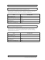
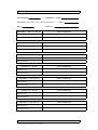
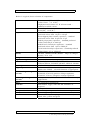
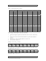
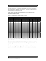
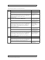
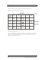
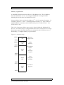
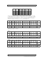
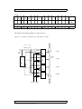
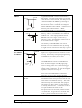
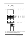
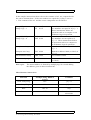
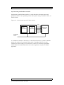
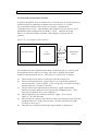
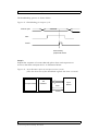
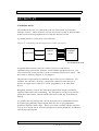
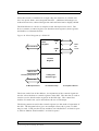
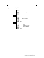
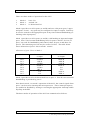
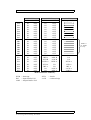
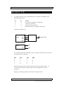
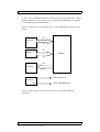
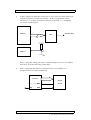
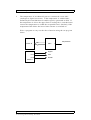
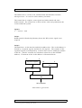
PRO G RAM M AB LE P ER IPH ER A L I N T ERF ACE (PP I)
There are three modes of operation for the 8255:
1.
2.
3.
Mode 0:
Mode 1:
Mode 2:
basic I/O
strobed I/O
bi-directional I/O
Mode 0 provides two 8-bit ports (A and B) and two 4-bit ports (port C upper
and port C lower). Any port may be configured as input or output. Data may
be read or written to the appropriate port at any time without handshaking (or
latching at the input ports).
Mode 1 provides two 8-bit ports (A and B), with latching at input and output
ports. Port C bits become handshaking lines for ports A and B. Six bits of
port C are used for handshaking and control, three for port A and three for
port B. The remaining two bits may be used as I/O bits. The table below
shows allocation of port C bits in mode 1 control.
Allocation of port C bits in Mode 1
Mode 1
PC0
PC1
PC2
PC3
PC4
PC5
PC6
PC7
Ports A and B
as Input
INTR B
IBF B
/STB B
INTR A
/STB A
IBF A
I/O
I/O
Ports A and B
as Output
INTR B
/OBF B
/ACK B
INTR A
I/O
I/O
/ACK A
/OBF A
Mode 2 provides an 8-bit bi-directional bus on port A. Port B is not used and
handshaking is provided by port C.
Note that in mode 1 or mode 2 operation of the 8255, the control signals from
port C can be used to interrupt the microprocessor. These interrupt requests
are enabled or disabled by setting or resetting the appropriate interrupt enable
flip-flop in the PPI.
The three modes of operation of the 8255 are summarised as follows:
E LE C TR O N I C S : M I C R O P R O C E S S O R S Y S TE M S H AR D W A R E ( A H )
117
© Le a r n i n g a n d T e a c h i n g S c o t l a n d