1
MICROWAVE OVEN
CE735GV (GREEN)
SERVICE Supplement
Manual
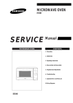
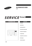
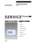
MICROWAVE OVEN
CONTENTS
1. Precaution
2. Control Panel
3. Exploded View & Parts List
4. Schematic Diagrams
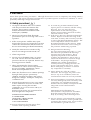
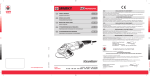
Specifications
TIMER
60 MINUTES
POWER SOURCE
230V/50HZ, AC
POWER CONSUMPTION
MICROWAVE : 1,400W
GRILL : 1100W
425
255
595
850W
127
0
OUTPUT POWER
2
3
60
4
50
5
40
6
30
20
7
10
C
SEF
É
R
A
M
I
Q
U
E
-
É
M
A
GRIL
I
L
FROM127 TO 850W
(6 LEVEL POWER)
1
9
(IEC-705 TEST PROCEDURE)
8
CE735G
OPERATING FREQUENCY
2,450MHz
MAGNETRON
OM75PH(31)
COOLING METHOD
COOLING FAN MOTOR
OUTSIDE DIMENSIONS
191/4"(W) x 1027/32"(H) x 143/8"(D)
NET WEIGHT
36.3 LBS.
SHIPPING WEIGHT
39.6 LBS.
PRECAUTIONS TO BE OBSERVED BEFORE AND DURING
SERVICING TO AVOID POSSIBLE EXPOSURE TO EXCESSIVE
MICROWAVE ENERGY
(a) Do not operate or allow the oven to be
operated with the door open.
(b) Make the following safety checks on
all ovens to be serviced before activating
the magnetron or other microwave
source, and make repairs as necessary:
(1) Interlock operation,
(2) proper door closing,
(3) seal and sealing surfaces (arcing,
wear, and other damage),
(4) damage to or loosening of hinges
and latches,
(5) evidence of dropping or abuse.
(c) Before turning on microwave power
for any service test or inspection within
the microwave generating
compartments, check the magnetron,
wave guide or transmission line, and
cavity for proper alignment, integrity,
and connections.
(d) Any defective or misadjusted
components in the interlock, monitor,
door seal, and microwave generation
and transmission systems shall be
repaired, replaced, or adjusted by
procedures described in this manual
before the oven is released to the owner.
(e) A Microwave leakage check to verify
compliance with the Federal
performance standard should be
performed on each oven prior to release
to the owner.
Samsung Electronics
1. Precaution
Follow these special safety precautions. Although the microwave oven is completely safe during ordinary
use, repair work can be extremely hazardous due to possible exposure to microwave radiation, as well as
potentially lethal high voltages and currents.
1-1 Safety precautions (
)
1. All repairs should be done in accordance
with the procedures described in this
manual. This product complies with
Federal Performance Standard 21 CFR
Subchapter J (DHHS).
2. Microwave emission check should be
performed to prior to servicing if the oven is
operative.
3. If the oven operates with the door open :
Instruct the user not to operate the oven and
contact the manufacturer and the center for
devices and radiological health immediatly.
4. Notify the Central Service Center if the
microwave leakage exceeds 5 mW/cm2
5. Check all grounds.
6. Do not power the MWO from a "2-prong"
AC cord. Be sure that all of the built-in
protective devices are replaced. Restore any
missing protective shields.
7. When reinstalling the chassis and its
assemblies, be sure to restore all protective
devices, including: nonmetallic control
knobs and compartment covers.
8. Make sure that there are no cabinet openings
through which people--particularly
children--might insert objects and contact
dangerous voltages. Examples: Lamp hole,
ventilation slots.
9. Inform the manufacturer of any oven found
to have emmission in excess of 5 mW/cm2,
Make repairs to bring the unit into
compliance at no cost to owner and try to
determine cause.
Instruct owner not to use oven until it has
been brought into compliance.
SAMSUNG ELECTRONIS FRANCE
S.A.PARIS NORD
305,RUE DE LA BELLE ETOILE
B.P.50051-95947 ROISSY
C.D.G CEDEX FRANCE
11. To avoid any possible radiation hazard,
replace parts in accordance with the wiring
diagram. Also, use only the exact
replacements for the following parts:
Primary and secondary interlock switches,
interlock monitor switch.
12. If the fuse is blown by the Interlock Monitor
Switch: Replace all of the following at the
same time: Primary and secondary switches,
as well as the Interlock Monitor Switch. The
correct adjustment of these switches is
described elsewhere in this manual. Make
sure that the fuse has the correct rating for
the particular model being repaired.
13. Design Alteration Warning:
Use exact replacement parts only, i.e., only
those that are specified in the drawings
and parts lists of this manual. This is
especially important for the Interlock
switches, described above. Never alter or
add to the mechanical or electrical design
of the MWO. Any design changes or
additions will void the manufacturer's
warranty.10.Always unplug the unit's AC
power cord from the AC power source
before attempting to remove or reinstall
any component or assembly.
14. Never defeat any of the B+ voltage
interlocks. Do not apply AC power to the
unit (or any of its assemblies) unless all
solid-state heat sinks are correctly installed.
15. Some semiconductor ("solid state") devices
are easily damaged by static electricity. Such
components are called Electrostatically
Sensitive Devices (ESDs). Examples include
integrated circuits and field-effect
transistors.
Immediately before handling any
semiconductor components or assemblies,
drain the electrostatic charge from your
body by touching a known earth ground.
16. Always connect a test instrument's ground
lead to the instrument chassis ground before
connecting the positive lead; always remove
the instrument's ground lead last.
10. Service technicians should remove their
watches while repairing an MWO.
Samsung Electronics
1-1
Pretaution
1-2 Special Servicing Precautions (Continued)
17. When checking the continuity of the witches
or transformer, always make sure that the
power is OFF, and one of the lead wires is
disconnected.
18. Components that are critical for safety are
indicated in the circuit diagram by
shading,
or
.
19. Use replacement components that have the
same ratings, especially for flame resistance
and dielectric strength specifications. A
replacement part that does not have the
same safety characteristics as the original
might create shock, fire or other hazards.
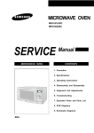
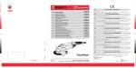
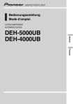
1-3 Special High Voltage Precautions
1. High Voltage Warning
Do not attempt to measure any of the high
voltages--this includes the filament voltage
of the magnetron. High voltage is present
during any cook cycle.
Before touching any components or wiring,
always unplug the oven and discharge the
high voltage capacitor (See Figure 1-1)
2. The high-voltage capacitor remains charged
about 30 seconds after disconnection. Short
the negative terminal of the high-voltage
capacitor to the oven chassis. (Use a
screwdriver.)
3. High voltage is maintained within specified
limits by close-tolerance, safety-related
components and adjustments. If the high
voltage exceeds the specified limits, check
each of the special components.
Fig. 1-1. Discharging the High Voltage Capacitor
1-2
Samsung Electronics
2. Control Panel
425
255
595
850W
127
0
1
2
3
60
50
4
40
5
6
30
20
7
10
9
8
CE735G
Samsung Electronics
2-1
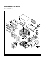
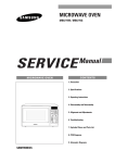
3. Exploded Views and Parts List
3-1 Exploded Views
M1
D5
M25
M39
D10
D1
D7
D9
M27
D8
M40
M2
M28
D6
D4
M37
M3
M4
D2
M5
D3
M38
M6
M8
M13
M7
M24
M9
M10
M12
M11
M41
M22
M35
M42
M18
M26
B1
M21
M30
M23
M36
B3
B2
M29
M31
M20
C6
B4
C4
M32
C5
M15
M14
M33
C3
C8
C7
M17
C2
C1
M16
M19
3-1
M34
Samsung Electronics
Exploded Views and Parts List
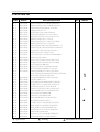
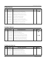
3-2 Main Parts List
Ref. No.
Parts No.
M 1
M 2
M 3
M 4
M 5
M 6
M 7
M 8
M 9
M 10
M 11
M 12
M 13
M 14
M 15
M 16
M 17
M 18
M 19
M 20
M 21
M 22
M 23
M 24
M 25
M 26
M 27
M 28
M 29
M 30
M 31
M 32
M 33
M 34
M 35
M 36
M 37
M 38
M 39
M 40
M 41
M 42
DE70-30116F
DE61-50323A
DE61-30008A
DE61-70060A
DE47-70073A
DE63-20017A
DE60-40009B
DE61-50021A
DE61-50027B
DE61-50025A
4713-001031
DE31-30031A
DE91-40095A
DE61-50106A
2501-001015
DE59-40001A
DE91-70061B
DE47-20174A
DE61-40017A
DE80-10003A
DE31-10154A
DE71-60013A
DE63-90035G
DE27-10020A
DE39-20058E
DE47-20008A
DE71-60010A
DE26-10099A
DE74-20102B
DE92-90436A
DE67-60002A
DE74-70071B
DE03-30035A
DE47-20009A
DE39-40569A
DE39-40409A
DE71-60298A
DE65-20014A
DE93-20001A
DE66-90013A
: Option Parts
Samsung Electronics
Description/Specification
PANEL-OUTER;SECC T0.6 GREEN-SPRAY W351.7
BRACKET-UPPER;ALSTAR T0.6 W385 L205 M624
SUPPORTER-HEATER;ALUMINA T12 CE745G
SPRING-PLATE;SK-5 T0.5
HEATER-GRILL;230V 1100W 47OHM 6.8
GASKET-HEATER;BRASS T1.5 OD30.5 ID22.5
WASHER-TEFLON;SLOT ID22.2 OD28 T1.2 TEFL
BRACKET-FLANGE;SECC1 T0.8 32 32
BRACKET-HEATER;SECC T1.0 W51 L55 CE945GF
BRACKET-EARTH;BSS2-A T1.0 CE745G
LAMP-INCANDESCENT;230V,173mA,40W ORG,-,-,25
FAN-MOTOR;SMF745EA 230V/50HZ ASSY-FAN-MO
ASSY NOISE FILTER;SN-E10D(N) 250V 10A “2
BRACKET-HVC;SECC T0.8 W31 L125.8
C-OIL;HCH212100C 1.0UF,2100V 35X54X80,20MM,
DIODE-H.V;HVR-1X-32B-12
ASSY-H.V.FUSE;THV060T-0750-H 5KV0.75A RE
THERMOSTAT;NT-101NA 8XH 120 110 23.8MM
FOOT;PP(A353) BLK MW5630T
BASE-PLATE;SGCC1-Z T0.8 W340 L550 M745
MOTOR-DRIVE;M2HJ49ZR02,ST-16 21V 5/6
COVER-CEILING;MICA T0.5 W52 L118 CE745G
ASSY CONTROL-BOX;230V50HZ CE735GV/XEF DEEP-GRN
ASSY DOOR;CE735GV/XEF DEEP-GRN
CUSHION-RUBBER;DFA20 T2 W190 L100 BLK
COIL-MC CHOKE;TC 101
ASSY POWER CORD;KKP4819D/B232 230V/16A L
THERMOSTAT;CS-7S(100/60)187Y 250V7.5A 10
COVER-AIR;PP(TB53) T1.7 WHT 64G M745
TRANS-H.V;SHV-745EG1 230V 2230V/3.10V 50
TRAY-COOKING;GLASS T5.0 PI288 780G M745
ASSY-GUIDE ROLLER;MW4370W
COUPLER;PPS 5GR BRN M97G45
RACK-WIRE;MSWR3 PI3 PI230 HI80 SNC2
MAGNETRON;OM75PH((31)ESS
THERMOSTAT;CS-7SA(160/60)187Y 250V7.5A 1
WIRE HARNESS-A;230V50HZ CE935G/CE73
WIRE HARNESS-E;230V50HZ M9G45 CTW
COVER-BACK;SECC T0.6 W273 L633 M6Q45
CABLE CLAMP;DA-6N NY-66
ASSY BODY LATCH;2ND-W1 M97G45/M9745
LEVER-DOOR;POM(F20-01) NTR MW5630T
: Warning
Q'ty
Remarks
1
1
1
1
1
1
1
1
1
1
1
1
1
1
1
1
1
1
2
1
1
1
1
1
1
1
1
1
1
1
1
1
1
1
1
1
1
1
1
1
1
:Electrostatically Sensitive Devices
3-2
Exploded Views and Parts List
3-3 Door Parts List
Ref. No.
Parts No.
Description / Specification
Q'ty
D 1
DE64-40007D
DOOR-A;ABS(VH-0370D) T3 GRN M745GR
1
D 2
DE64-40006A
DOOR-KEY;POM(TC3005) T2.0 12GR BLK CE9
1
D 3
DE61-70033A
SPRING-KEY;ES HSWR10 PI0.6 D6.0 L22.3 BL
1
D 4
DE67-20004P
SCREEN-DOOR;PC T1.5 W173.6 L373.5 CE735G
1
D 5
DE92-50126B
ASSY DOOR-E;COATING BLK CE745G
1
D 6
DE64-40008B
DOOR-C;PP T1.5 W L G BLK CE745G
1
D 7
DE01-00003B
FILM-DOOR;PC T0.2 W143 L265 TRP CE745G
1
D 8
DE02-00125A
TAPE-DOUBLE FACE;ACRYL T0.45 W9 WHT WF103
1
D 9
DE61-80004A
HINGE-LOWER;SCP1 T2.3 ZN-COATING BLK
1
D 10
DE61-80005A
HINGE-UPPER;SCP1 T2.3 BLK ZN-COATING
1
Remarks
3-4 Control Parts List
Ref. No.
Parts No.
Description/Specification
Q'ty
C 1
DE66-20006C
BUTTON-PUSH;ABS(HR-0370D) GREEN M745GR
1
C 2
DE61-70076A
SPRING-BUTTON;HSWR PI0.6
1
C 3
DE64-10123D
KNOB;ABS 5G DEEP-GRN M735V/XEF
2
C 4
DE72-70006N
CONTROL-PANEL;ABS T3 W106 L261 DEEP-GRN
1
C 5
DE45-10076A
TIMER-ASSY;TMFK60MTB1 220V/240V 310-GRIL
1
C 6
3501-000309
RELAY-POWER;CHP11-A240S-250V15A 240V,375
1
C 7
DE39-40333B
WIRE HARNESS-B;230V50HZ CE735G/CE935G
1
C8
DE93-30532A
ASSY CONTROL-PSNRL;CE735GV/XEF DEEP-GRN
1
Remarks
3-5 Body Latch Parts List
Ref. No
Parts No.
Description / Specification
Q'ty
B 1
DE66-40001A
LATCH-BODY;POM(F20-02) 40GR NTR
1
B 2
3405-000178
SWITCH-MICRO;250V,15A,200gf,SPST-NO
2
B 3
3405-000175
SWITCH-MICRO;250V,15A,200gf,SPST-NO
1
B 4
DE66-90001A
LEVER-SWITCH;P.O.M(F20-02) 2 6 NTR SND-W
1
3-3
Remarks
Samsung Electronics
Exploded Views and Parts List
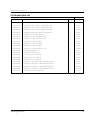
3-6 Standard Parts List
Parts No.
Description / Specification
Q'ty
Remarks
DE60-10012A
SCREW-TAP TITE;TH + 3 M4 L10 SWR10 ZPC2 TOO
1
B/DR-M
DE60-10012A
SCREW-TAP TITE;TH + 3 M4 L10 SWR10 ZPC2 TOO
1
N-F-EA
DE60-10012A
SCREW-TAP TITE;TH + 3 M4 L10 SWR10 ZPC2 TOO
1
P-C-EA
DE60-10013A
SCREW-ASSY TAP;TH 2S 4 L12 MSWR3 ZPC3 FIBER
2
MO/FAN
DE60-10018A
SCREW-ASSY MACHINE;PH M4X0.7P 8 MSWR10 S
2
B/EATH
DE60-10024A
SCREW-PH;PH + 4 L8 MSWR10 ZPC3
2
B/HEAT
DE60-10033A
SCREW-TH;TH + M4 L10 MSWR10 FEFZY
2
HI-LOW
DE60-10033A
SCREW-TH;TH + M4 L10 MSWR10 FEFZY
2
HI-UPP
DE60-10052A
SCREW-TAP PH;PH M4 L8 FEFZY
1
GR-TCO
DE60-10069A
SCREW-TAP TH;TH M4 L10 FRFZY
3
B/UPPE
DE60-10069A
SCREW-TAP TH;TH M4 L10 FRFZY
1
CV/AIR
DE60-10072A
SCREW-TAP TH;TH M4 L16 FEFZY 2-SLOT
1
CB-CMP
DE60-10080A
SCREW-WASHER;M5 L12 2S
4
MGT
DE60-10080A
SCREW-WASHER;M5 L12 2S
4
TNS-HV
DE60-10082A
SCREW-A;M4 L12 2S TOOTHED
4
B/PLTE
DE60-10082A
SCREW-A;M4 L12 2S TOOTHED
1
CN-BOX
DE60-10082A
SCREW-A;M4 L12 2S TOOTHED
2
LATCH
DE60-10098A
SCREW-ASSY TAPTITE;PH TC M4X8 SWRCH18A ZPC2
1
B/HVC
DE60-10098A
SCREW-ASSY TAPTITE;PH TC M4X8 SWRCH18A ZPC2
1
CV-TCO
DE60-10098A
SCREW-ASSY TAPTITE;PH TC M4X8 SWRCH18A ZPC2
2
M/DRIV
DE60-10098A
SCREW-ASSY TAPTITE;PH TC M4X8 SWRCH18A ZPC2
2
MG-TCO
DE60-10122A
SCREW-TAP TH;TAP TH 2-4X8 FE FN
2
C-CEIL
Samsung Electronics
3-4
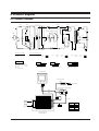
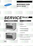
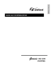
4. Schematic Diagrams
4-1 Schematic Diagrams
ROTRY S/W
(MWO)
CAVITY TCO
BLU
C3
230V
BLK
COM
BRN
VPC
H.V.CAPACITOR
F
FA
MAGNETRON
S/W
SECONDARY S/W
(MWO)
(S/W)
(GRILL)
(S/W)
GRILL
(MWO)
(S/W)
(GRILL)
(S/W)
WIRING COLOR
BRN : BROWN BLU : BLUE
WHT : WHITE ORG : ORANGE
RED : RED
YEL : YELLOW
BLK : BLACK
Y/G : YELLOW GREEN
NO
FUNCTION ROTARY S/W
MWO
COOK OFF
NC
BRN
BRN
MGT
TCO
CONDITION OF OVEN
H.V.FUSE
230V
BRN
DOOR IS OPENED
T/M
MONITOR S/W
F/M
INRUSH COIL
D/M
BLU
BLU
C2
FUSE
250V10A
250V1.6A
0V
FAN-MOTOR
DRIVE-MOTOR
1ND
RESISTOR
LINE CAPACITOR
HEATER
LAMP
H.V.DIODE
FUSE
21V
ORG
BRN
OV
BLU
WHT
GRILL
TCO
230V40W
YEL
L
RESISTOR
H.V.TRANS
ORG
ORG
BLK
BLU
ORG
WHT
ROTARY S/W
(GRILL)
YEL
POWER
CORD
230V/50HZ
INRUSH
RELAY
BLU
YEL
BLU
BLK
N
BLU
BRN
L
ASSY CHOKE P.C.B
TIMER-MOTOR
BLU
BRN
PRIMARY
S/W
BLU
TIMER S/W
COM NO
BLU BLK
COM NO
BLU YEL
BRN
COMBI
NC
COM NO
BRN
PRIMARY SWITCH
SECONDARY SWITCH
(MWO)
(S/W)
(GRILL)
(S/W)
BLU BLU
BRN
BRN BRN
MONITOR SWITCH
MAGNETRON
HIGH VOLTAGE
DIODE
FA
TO CHASSIS
F
HIGH VOLTAGE CAPACITOR
RED
RED
RED
H.V.FUSE
BLK
WHT
RED
SYMBOL COLOR
BRN BROWN
BLK
BLACK
RED
RED
BLU
BLUE
HIGH VOLTAGE
TRANSFORMER
4-1
Samsung Electronics