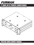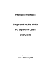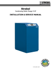
1
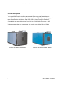
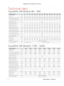
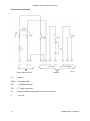
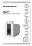
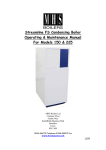
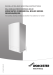
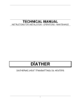
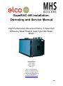
SupeRAC-AR Installation,
Operating and Service Manual
High Performance Reversed Flame, 3 Pass High
Efficiency Steel Shell & Tube Type Hot Water
Boiler
MHS Boilers Ltd
3 Juniper West
Fenton Way
Basildon Essex
SS15 6SJ
Main Tel: 01268 546700
Spares Tel: 01268 546771
Service Tel: 01268 546770
Technical Help: 01268 545772
Fax: 01268 888270
WWW.MHSBOILERS.COM
L318
SupeRAC-AR For Models 80 to 3600
CONTENTS
2
General description…………….…………………………………
page 3
Technical data……….....…................…...................................
page 4
General regulation
page 5
Clearances
...............…….......…..…...................................
page 7
Dimensions.......................………………….…………………....
page 8
Handling………………...............................……………............
page 9
Installation
page 9
Location……………………...........................................……….
page 9
Combustion chamber door opening and adjustment.............
page 9
Burner mounting......................................................................
page 10
Prevention of condensation.....................................................
page 10
Fuel supply…............................................................…….......
page 11
Fitting the case (models 80AR – 900)........................................
page 11
Mounting the control panel (models 1220 – 3600).................
page 12
Flue system ……………………..…………………………........
page 12
System water ....................................…….............................
page 13
Control panel schematic........................................................
page 14
Preliminary Checks................................................................
page 15
First start up…………………………………..…………............
page 15
User instructions.......................................…................……..
page 16
Operation / Controls..........................................………..........
page 16
Notes
page 18
©MHS Boilers 11/09/2012
SupeRAC-AR For Models 80 to 3600
General Description
The SupeRAC-AR series of boilers are reversed flame three pass forced draught
combustion type, carbon steel shell and tube appliances. Suitable for use with appropriate
power flame burners with Natural Gas, LPG, Light or Heavy Fuel Oil or Biodiesel.
23 models in the range with outputs from 81kW to 3610kW with efficiencies > 94%.
Working pressure 6bar (or upon request / to special order, either 8bar or 10bar)
SupeRAC-AR Models 80AR -900AR
3
SupeRAC-AR Models 1100AR -3600AR
©MHS Boilers 11/09/2012
SupeRAC-AR For Models 80 to 3600
4
©MHS Boilers 11/09/2012
SupeRAC-AR For Models 80 to 3600
General regulations
This documentation contains important information, which is a base for safe and reliable
installation, commissioning and operation of the SupeRac AR. Boiler. All activities described
in this document may only be executed by authorized companies.
Changes to this document may be effected without prior notice. We accept no obligation to
adapt previously delivered products to incorporate such changes.
Only original spare parts may be used when replacing components on the boiler, otherwise
warranty will be void.
Application
The SupeRac AR Boiler may be used for heating and hot water production purposes only.
The boiler should be connected to closed systems with a maximum temperature of 100ºC
(high limit temperature); maximum set point temperature is 90ºC.
Norms and regulations
When installing and operating the boiler, all applicable norms (European and local) should
be fulfilled:
• Local Building regulations for installing combustion air and flue gas systems;
• Regulation for connecting the boiler to the electrical appliance;
• Regulations for connecting the boiler to the local gas network;
• Norms and regulations according to safety equipment for heating systems;
• Any additional local laws/regulations with regard to installing and operating heating
systems.
− 92 / 42 / EEC Boiler efficiency directive − 90 / 396 / EEC Gas appliance directive −
73 / 23/ EEC Low voltage directive − 89 / 336 / EEC EMC directive
− EN 656 Gas-fired central heating boilers – Type B boilers of nominal heat input exceeding
70 kW but not exceeding 300 kW
− EN 15420 Gas-fired central heating boilers - Type C boilers of nominal heat input
exceeding 70 kW, but not exceeding 1000 kW
− EN 15417 Gas-fired central heating boilers - Specific requirements for condensing boilers
with a nominal heat input greater than 70 kW but not exceeding 1000 kW
− EN 13836 Gas fired central heating boilers - Type B boilers of nominal heat input
exceeding 300 kW, but not exceeding 1000 kW
− EN 15502-1 Gas-fired central heating boilers - Part 1: General requirements and tests
− EN 55014-1 Electromagnetic compatibility - Requirements for household appliances,
electric tools and similar apparatus Part 1: Emission
− EN 55014-2 Electromagnetic compatibility - Requirements for household appliances,
electric tools and similar apparatus Part 2: Immunity - Product family standard
− EN 61000-3-2 Electromagnetic compatibility (EMC) - Part 3-2: Limits - Limits for harmonic
current emissions (equipment input current 16 A per phase)
− EN 61000-3-3 Electromagnetic compatibility (EMC) - Part 3-3: Limitation of voltage
changes, voltage fluctuations and flicker in public low-voltage supply systems, for
equipment with rated current 16 A per phase and not subject to conditional connection
− EN 60335-1 Household and similar electrical appliances -Safety - Part 1: General requirements
− EN 50165 Household and similar electrical appliances -Safety - Part 2-102: Particular
requirements for gas, oil and solid-fuel burning appliances having electrical connections
5
©MHS Boilers 11/09/2012
SupeRAC-AR For Models 80 to 3600
The following Codes of Practice are also applicable: BS 6644 : 2011 Specification for gas fired hot water boilers of rated inputs between 70kW
(net) and 1.8MW (net) (2nd and 3rd family gases).
BS 6880:1988 Code of Practice for low temperature hot water heating systems of output
greater than 45kW. Parts 1, 2 & 3.
BS 6891:2005 + A2:2008 Specification for installation of low-pressure gas pipework of up to
35mm (R11/4) in domestic premises (2nd family gases).
BS 7593:2006 Code of Practice for treatment of water in domestic hot water central heating
systems.
BS 7671:2008 Requirements for electrical installations.
Seventeenth Edition
IEE Wiring Regulations.
BS EN 12828 2003 Heating systems in buildings – Design for water based heating systems.
CISBE Guide reference sections B7, B11 and B13.
CP342 Part 2: 1974 Code of Practice for centralized hot water supply.
IGE/UP/1 or 1A Gas Tightness Testing & Purging of Commercial Industrial Gas Installations
IGE/UP/2 Gas installation pipework, boosters and compressors on Industrial and
Commercial premises.
IGE/UP/4 Commissioning of gas fired plant on industrial and commercial premises.
IG/UP/10 edition 3 Installation of gas appliances in Industrial and Commercial premises.
Part 1: Flued appliances.
Through their unique construction, the SupeRac Boiler range of central heating units are
renowned for their:
- High thermal output
- Durability
- Can be supplied in a wide range of models
Through active and market oriented research, MHS Boilers Ltd is in a position to offer
solutions for the most challenging heating requirements.
The supplier
MHS Boilers Ltd are proud to supply and technically support the SupeRac AR Boiler Range
of boilers throughout the United Kingdom. For advice or more information please contact
your local sales representative or our head office via 01268 546700. or via our website
www.mhsboilers.com
6
©MHS Boilers 11/09/2012
SupeRAC-AR For Models 80 to 3600
This document
The present documentation has been prepared with the following target groups in mind:
- The technical consultant
-The installer
- The maintenance technician
-The user
MHS Boilers Ltd has opted to make the technical documentation as comprehensive as
possible in the form of this book, in order to ensure that these target groups have all the
information they need. As the supplier we would be happy to help you in connection with any
additional information that you may require. This document covers the following aspects
relating to the boilers:
- General description
- Technical specifications
- Requirements for design and installation
-Maintenance instructions
The operating instructions for the user have been affixed to the appliance itself.
Service
For commissioning and assistance in maintenance matters, please contact the Services
Department via 01268 546770.
General restrictions
MHS Boilers Ltd products should always be used, installed and maintained in accordance
with the statutory requirements, specifications and standards applicable to these
installations. All the data, information and suggestions concerning its products provided by
MHS Boilers Ltd are based on careful study. However, the use, installation and operation of
the same are outside the control of MHS Boilers Ltd and neither MHS Boilers Ltd nor any
other organisations associated with it, accept any liability for the same.
Clearances.
Sufficient space must be allowed as necessary at the rear of the boiler for connection of the
flue components and access to the flue collector hood clean-out port.
A minimum of 450mm must be allowed at either side of the boiler/s with attention being paid
to the space required to fully open the combustion chamber door with the burner mounted
upon it
Clearance at the front of the boiler must allow for cleaning of the flue tubes which run
horizontally for the entire length of the boiler minus the thickness of the combustion chamber
door and the depth of the flue collector hood. The clearance required at the front, measured
from the front of the boiler body (excluding the door) must not be less than dimension B1 in
the following tables.
7
©MHS Boilers 11/09/2012
SupeRAC-AR For Models 80 to 3600
8
©MHS Boilers 11/09/2012
SupeRAC-AR For Models 80 to 3600
Handling / Scope of Supply
Models up to and including 900AR are supplied with the control panel, insulating blankets,
ceramic fibre packing material (for sealing around the burner blast tube) and documentation
packed inside the combustion chamber. The casing and burner assembly are supplied in
separate cartons.
Models 1100AR to 3600AR are factory pre-insulated and have their casing panels fitted; the
control panel, documentation and ceramic fibre packing material (for sealing around the
burner blast tube) is packed inside the combustion chamber
The boilers are equipped with lifting eyes to assist with the moving and handling of the boiler
body
Installation
Location
The location chosen for the installation of the boiler/s must be flat and level to facilitate
correct alignment of connections and must be capable of supporting the units when full of
water.
The floor or plinth must be fireproof in accordance with BS 6644.
The plant room must have sufficient space for the installation of the boilers, associated
pipework, pumps, controls, flues, ventilation and with due allowance to access and servicing
of other pieces of equipment.
Adequate space must be provided around the boiler to allow the removal of the
burner and opening of the combustion chamber door and removing the flue baffles.
Combustion chamber door opening and adjustment
The door can be opened from both sides (except for models 2580AR – 3600AR).
The doors are normally supplied opening from left to right.
To open the door, remove the fixing nuts from the left hand side.
To reverse the direction of opening of the combustion chamber door it will be
necessary due to the size and weight of door to utilise lifting gear.
Attach lifting gear via the two holes in the upper part of the door assembly.
Remove the 4 door retaining nuts
Carefully remove the door assembly and set to one side
Remove the jam nuts from the tie rods on the left hand side and transfer them
to the rods at the right hand side (positioning them approximately the same as
when on the left hand ties rods).
Carefully offer up the door assembly and remount onto the tie rods and retain
using previously removed nuts. Release and remove any lifting
aids/equipment.
9
©MHS Boilers 11/09/2012
SupeRAC-AR For Models 80 to 3600
To adjust and tighten the door:
Slightly slacken back the jam nuts.
Tighten the door evenly onto the front of the boiler body using the door
retaining nuts/capstans to form a gas tight seal.
Re-tighten as necessary the jam nuts back against the bush seating on the
door assembly.
Proceed to mount the burner, following which, check and adjust as necessary,
the fitting of the combustion chamber door against the boiler body
Burner mounting
Follow carefully the instructions supplied with burner.
The burner mounting plate must be cut and drilled as appropriate to the dimensions of the
burner to be utilised. It is extremely important that any space around the burner blast tube is
packed with the ceramic fibre material supplied with the boiler.
Ceramic fibre material packed-in to
seal any gaps between the burner
blast tube and the insulation pad on
the combustion chamber door
Prevention of Condensation
Boiler
It is most important to ensure that the return water temperature entering the boiler is
maintained above the dew point temperature of the flue gases. An acceptable method of
creating of this facility is to install a link pipe between the main flow and return pipes serving
the boiler, with a pump and a non-return valve included (as shown above). The pump needs
only to be of a very low head and the flow rate should be in the order of 25-30% of the mass
flow of the main boiler pump. The anti-condensation pump should be controlled by a
thermostat mounted onto the return pipe adjacent to the return pipe connection of the boiler
and the temperature setting should be nominally 60°C for gas firing and 50°C for oil firing.
10
©MHS Boilers 11/09/2012
SupeRAC-AR For Models 80 to 3600
Fuel supply
Gas supply pipework must be in accordance with BS 6891 or IGE/UP/2
The gas installation must be soundness tested to and purged in accordance with BS 6891 or
IGE/UP/1 & IGE/UP/1A.
Gas connections to the burner shall not be smaller than the connection size on the burner.
If a gas pressure booster is required (refer to the manual supplied with the burner), then the
controls must include a low gas pressure cut off device at the inlet to the booster. It may be
necessary to install a governor between the booster and the burner gas train should the inlet
pressure to the gas train exceed 50mbar.
The oil storage and supply system should be designed and installed in accordance
with BS.5410 Part 2. If liquid bio fuel is being used, ensure all components are suitable for
such use. Liquid bio fuel must be in accordance with BS EN 1423.
The oil supply pipe between storage tank and burner should be installed using copper, steel
or aluminium pipe and fittings. Galvanised pipes are not considered suitable
The oil supply pipe should terminate adjacent to the burner with an isolating valve and
should include metal bowl type filter.
Fitting the case (Models 80AR – 900AR)
See Fig.1
It is advised to complete the installation of the boiler before fitting the casing and control
panel assembly.
Wrap the insulating blanket (1) around the drum of the boiler body (making cuts/apertures for
the flow and return pipes as necessary). Retain the insulation in place using the securing
bands.
Next, fit the left hand side casing panel (3) by locating the lower retaining bracket of the
panel inside the lower lateral rail of the boiler body assembly, and then hook the top part of
the panel on to the upper structural rail of the boiler body.
Repeat for the right hand side panel (2).
Temporarily position the top cover panels (4) & (5) on to the top of the boiler; unpack the
control panel (6) and carefully extend the capillary tubes of the thermostats etc and pass
them through the hole in the top cover panel (4). Insert the sensing bulbs of the instrument
capillaries into the thermostat pockets adjacent to the flow pipe tube on the top of the boiler.
Secure the control panel to the top cover panel (4), and then finally locate the top casing
panels.
11
©MHS Boilers 11/09/2012
SupeRAC-AR For Models 80 to 3600
5
6
4
3
1
Fig.1
2
Mounting the control panel. (Models 1220 - 4070)
Mount the control panel using the supplied bracket on to the casing at a suitable and
convenient location on the top or side of the boiler casing panels.
The instrument capillaries must be carefully extended and located into the thermostat
pockets adjacent to the flow pipe assembly on the boiler body.
Flue system
SupeRAC Boilers are suitable for open flue type installations B23 taking air for combustion
from the room in which it is installed; the boiler plant room must be suitably ventilated to
BS6644.
The flue pipe and components serving the SupeRAC boiler must be suitable for working
temperatures of not less than 250°C and should be thermally insulated.
The route of the flue short be as short as possible and sized appropriately to ensure
complete evacuation of combustion gases without causing excessive back pressure.
The flue should generate sufficient draught to overcome its own resistance with a minimum
negative draught at the boiler flue connection in the order of 10 – 30Pa.
If the draught generated in the flue is likely to exceed 30Pa, then a suitable draught stabiliser
should be installed locally to the flue connection at the boiler.
The flue installation should comply with the requirements of the
Clean Air Act 1956, BS 6644, BS5440 and IGE/UP/10 as applicable.
12
©MHS Boilers 11/09/2012
SupeRAC-AR For Models 80 to 3600
System water
Care must be taken to ensure that system pipe work is cleansed and flushed prior to filling
the boiler.
The system water must be treated with a good quality corrosion inhibitor and the water
condition must be maintained to ensure that the following values are observed:
pH
8.3 – 9.5
Hardness
<100mg CaCO3/litre
Chlorides
<50mg/litre
Oxygen
<0.1mg/litre
Phosphates <30/mg/litre
It is strongly recommended to install coarse strainers to protect the boiler, pumps, valves etc
from the effects of solid debris or particles within the system.
13
©MHS Boilers 11/09/2012
SupeRAC-AR For Models 80 to 3600
Control panel schematic
On / Off
Supply 230V 1ph 50Hz
To Burner
IG
Isolator
TSAH
Limit thermostat
TR1
1st Stage thermostat
TR2
2nd Stage thermostat
TA
External enable contacts (remove link if connected)
F
Fuse 4A
14
Hi / Lo (2nd Stage)
Fig.??
©MHS Boilers 11/09/2012
SupeRAC-AR For Models 80 to 3600
Preliminary checks before first firing
Check that control panel instrument bulbs are correctly positioned in the thermostat
pockets.
Ensure that the flue tube turbulators do not protrude from the front of the tubes and
that no foreign objects are within the combustion chamber.
Check that any gaps between the burner blast tube and the combustion chamber
door have been filled using high temperature ceramic fibre material.
Check that the system has been filled with water and is vented and that the pressure
is above 1bar and within the maximum limits of the plant.
Ensure that an appropriately rated safety relief valve has been fitted and where
necessary a pressure limiter.
Check that combustion chamber door has been closed correctly.
Check that pumps rotate freely and in the correct direction.
Check fuel supplies have been appropriately tested for soundness, have been
purged/vented and the fuel control valve is closed. Ask to view certificates. Gas
supplies should be tested and purged in accordance IGE/UP/1 or IGE/UP/1A as
appropriate
Check that the ventilation provision meets with the appropriate standards.
Check that the power supply is of the appropriate rating and adequately fused and
that an isolator is positioned adjacent to the boiler.
Ensure a heat load is available.
Check that flue pipe is securely connected /sealed onto appliance
First start up
Refer to the instructions supplied with the burner
Check that appropriate sized nozzles have been fitted (oil fired burner).
Check security and condition of flexible fuel lines (oil fired burner).
Check electrode condition, positioning and gaps as specified in the burner
manufacturer’s instructions
Make burner pre-settings for head positioning and air settings
Attach oil pressure gauge to burner oil pump (oil fired burner).
Ensure temperature controls are calling for heat
Turn on fuel supply at isolating valve
15
©MHS Boilers 11/09/2012
SupeRAC-AR For Models 80 to 3600
Turn on boiler at isolator and on/off on boiler control panel – the burner should start
its start-up and ignition process.
Check gas train (gas burner) and any pipework between isolating valve and burner
connection for leakage.
Check oil lines / oil connections for soundness (oil burner).
Adjust burner in accordance with the burner manufacturer’s instructions and allow the
burner to stabilise for approximately 10 – 15 minutes; following which take
measurements of combustion gases, fuel throughput (gas burner) and making any
further adjustments as necessary. Record measurements.
Switch off boiler, remove any gauges and refit test points.
Restart/stop boiler several times to check integrity of ignition system.
Check combustion chamber door for correct sealing.
Check flue joints for integrity.
Check water connections for soundness.
(For gas fired burner only), with burner firing, turn off gas supply and ensure burner
goes to lockout. Wait 45 seconds, turn on gas supply, and press reset button on
burner – ensure burner restarts normally.
Set controls to normal operational settings.
Instruct user on the operation of the boiler and its controls and safety functions.
User Instructions
Following the successful installation and commissioning procedures, the user must
be made aware of the lighting and operating instructions including a practical
demonstration.
This installation guide plus the burner instructions must handed over for safe keeping
and future reference.
Operation / Controls
The control panel includes two control thermostats which allows for the operation of
high / low firing (2 stage burners).
The left hand thermostat is for the control of the first stage (low fire) and should be
set to the actual final wanted flow temperature; the right hand thermostat is for the
control of the second stage (high fire0 and should be nominally set around 3-5
degrees lower than the first stage thermostat to allow the burner to reduce to it’s low
fire setting as the final setpoint water temperature is approached.
Care should be taken to ensure that the controls are set to avoid that the water
temperature within the system remains at a level where the return water temperature
is less than 60°C for gas firing or 50°C for oil firing.
16
©MHS Boilers 11/09/2012
SupeRAC-AR For Models 80 to 3600
If a modulating burner is being used, then the 4 core burner connection lead
(T6,T8,T7) should be ignored and not utilised. The thermostat sensing bulb for the
2nd stage control thermostat should not be located in the thermostat pocket, and the
temperature sensor supplied with the modulating burner temperature controls can be
substituted into the thermostat pocket in place of the 2nd stage thermostat sensing
bulb.
17
©MHS Boilers 11/09/2012
SupeRAC-AR For Models 80 to 3600
Notes
18
©MHS Boilers 11/09/2012