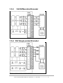
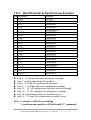
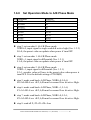
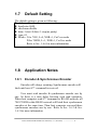
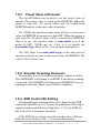
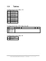
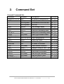
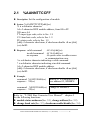
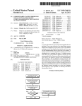
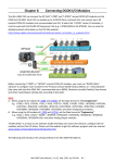
1
I-7083/7083D/7083B/7083BD
User’s Manual
I-7000 New Features
1. Self Tuner Inside
2. Multiple Baud Rate
3. Multiple Data Format
4. Dual WatchDog Inside
5. True Distributed Control
6. High Speed & High
Density I/O
Your Powerful Tools
Create New Ideas
Create New Applications
Warranty
All products manufactured by ICP DAS are warranted
against defective materials for a period of one year from the
date of delivery to the original purchaser.
Warning
ICP DAS assume no liability for damages consequent to
the use of this product. ICP DAS reserves the right to change
this manual at any time without notice. The information
furnished by ICP DAS is believed to be accurate and reliable.
However, no responsibility is assumed by ICP DAS for its use,
nor for any infringements of patents or other rights of third
parties resulting from its use.
Copyright
Copyright 2006 by ICP DAS. All rights are reserved.
Trademark
The names used for identification only maybe registered
trademarks of their respective companies.
I-7083/7083D/7083B/7083BD User Manual (V 1.1, Dec/2007) ------------------ 1
Table of Contents
1.
INTRODUCTION........................................................................................................................4
1.1
ENCODER COUNTING MODE ..................................................................................................5
1.2
PIN ASSIGNMENT...................................................................................................................8
1.3
SPECIFICATIONS ....................................................................................................................9
1.4
BLOCK DIAGRAM ................................................................................................................10
1.5
APPLICATION WIRING .........................................................................................................11
1.5.1
5V Differential Encoder.................................................................................................11
1.5.2
5V Single-ended Encoder...............................................................................................11
1.5.3
12V Differential Encoder...............................................................................................12
1.5.4
12V Single-ended Encoder.............................................................................................12
1.5.5
24V Differential Encoder...............................................................................................13
1.5.6
24V Single-ended Encoder.............................................................................................13
1.5.7
Mix-Mode Encoder .......................................................................................................14
1.6
1.6.1
Read Encoder & Z2,Z1,Z0.............................................................................................15
1.6.2
Read Synchronous Encoder ...........................................................................................15
1.6.3
Read Encoder & Synchronous Encoder.........................................................................16
1.6.4
Set the Preset Value of Encoder....................................................................................17
1.6.5
Clear Encoder to 0.........................................................................................................17
1.6.6
Set Operation Mode to CwCcw Mode............................................................................18
1.6.7
Set Operation Mode to PulseDir Mode..........................................................................19
1.6.8
Set Operation Mode to A/B Phase Mode .......................................................................20
1.7
DEFAULT SETTING ..............................................................................................................21
1.8
APPLICATION NOTES ...........................................................................................................21
1.8.1
Encoder & Synchronous Encoder..................................................................................21
1.8.2
Preset Value of Encoder ................................................................................................22
1.8.3
Encoder Counting Sequence ..........................................................................................22
1.8.4
XOR Control Bit Setting ................................................................................................22
1.9
2.
QUICK START ......................................................................................................................15
TABLES ...............................................................................................................................23
COMMAND SET.......................................................................................................................24
2.1
%AANNTTCCFF...............................................................................................................25
2.2
#AAN .................................................................................................................................26
2.3
#** ......................................................................................................................................27
2.4
~**......................................................................................................................................28
2.5
~AA0 ..................................................................................................................................29
2.6
~AA1 ..................................................................................................................................30
I-7083/7083D/7083B/7083BD User Manual (V 1.1, Dec/2007) ------------------ 2
3.
2.7
~AA2 ..................................................................................................................................31
2.8
~AA3ETT...........................................................................................................................32
2.9
~AAM ................................................................................................................................33
2.10
~AAO(NAME) .....................................................................................................................34
2.11
$AA2 ..................................................................................................................................35
2.12
$AA5 ..................................................................................................................................36
2.13
$AA6N ...............................................................................................................................37
2.14
$AADNM...........................................................................................................................38
2.15
$AAF ..................................................................................................................................39
2.16
$AAI...................................................................................................................................40
2.17
$AAM.................................................................................................................................41
2.18
$AASN ...............................................................................................................................42
2.19
$AAZN...............................................................................................................................43
2.20
$AAGN ..............................................................................................................................44
2.21
$AAPN(DATA)....................................................................................................................45
OPERATION PRINCIPLE.......................................................................................................46
3.1
INIT* PIN............................................................................................................................46
3.2
LED DISPLAY FORMAT .......................................................................................................47
3.3
7080(D) & 7083B(D)..........................................................................................................48
I-7083/7083D/7083B/7083BD User Manual (V 1.1, Dec/2007) ------------------ 3
1. Introduction
I-7000 is a family of network data acquisition and control
modules. They provide A/D, D/A, DI/O, Timer/Counter and other
functions. These modules can be remote controlled by a set of
commands. The common features of I-7083/7083B are given as
following:
z3 axis, 32-bit encoder counter
zEncoder counting mode: Cw/Ccw , Pulse/Direction, A/B Phase
zMaximum counting rate: 1MHz
zEncoder Input: A, B, Z differential
zInput Level: 5V, 12V/24V with external resistor
zA/B/Z signal isolation voltage: 2500V optical isolation
zBuilt-in XOR logic for active high or active low encoder input
The I-7083B will save the counter value to EEPROM when the
power goes off. The 7083D & 7083BD equip a 7-Seg interface to
display encoder value & ABZ status one by one.
More Information
Refer to “I-7000 Bus Converter User Manual” chapter 1
for more information as following:
1.1
1.2
1.3
1.4
I-7000 Overview
I-7000 RELATED DOCUMENTATION
I-7000 COMMON FEATURES
I-7000 SYSTEM NETWORK
CONFIGURATION
1.5 I-7000 Dimension
I-7083/7083D/7083B/7083BD User Manual (V 1.1, Dec/2007) ------------------ 4
1.1
Encoder Counting Mode
There are 3 counting modes, CC/PD/AB, given as follows:
Note: -1=0xffffffff, -2=0xfffffffe
I-7083/7083D/7083B/7083BD User Manual (V 1.1, Dec/2007) ------------------ 5
The internal counting logic is expected as active high. User can
use XOR control bit to select the proper waveform as follows:
Case 1: differential input, set XOR=1
Case 2: active high single-ended input, set XOR=0
Case3: active low single-ended input, set XOR=1
I-7083/7083D/7083B/7083BD User Manual (V 1.1, Dec/2007) ------------------ 6
If the value of XOR control bit is error, the encoder value will
have different errors given as follows:
z The counting direction will be inverted
z The encoder value has error count = 1
z The Z is inverted
User can use $AASN command to check the status of A,B,Z.
All A,B,Z are expected to be Low in the normal state & High in
the active state. The check sequences are given as follows:
step command
1 $01S0
2 $01S1
3 $01S2
response
!01M0
!01M0
!01M0
z
z
z
z
Step 1: check A0,B0 & Z0 must be all Low, M=mode
Step 2: check A1,B1 & Z1 must be all Low, M=mode
Step 3: check A2,B2 & Z2 must be all Low, M=mode
Refer to Sec. 2.18 for more information about $AASN
command
z Refer to Sec. 1.6.6, Sec. 1.6.7 & Sec. 1.6.8 for more
information about M=mode
Some error results are given as follows: (assume in the normal
state)
step command
response
1 $01S0
!01M7
2 $01S1
!01M7
3 $01S2
!01M7
z Step 1: XOR0 is setting error, A0,B0 & Z0 must be Low
z Step 2: XOR1 is setting error, A1,B1 & Z1 must be Low
z Step 3: XOR2 is setting error, A2,B2 & Z2 must be Low
I-7083/7083D/7083B/7083BD User Manual (V 1.1, Dec/2007) ------------------ 7
1.2
Pin Assignment
I-7083/7083D/7083B/7083BD User Manual (V 1.1, Dec/2007) ------------------ 8
1.3
Specifications
i-7083: 3-axis Encoder Module
i-7083D: i-7083 with LED Display
i-7083B: 3-axis Nonvolatile Encoder Module
i-7083BD: i-7083B with LED Display
Encoder Input
z Channels: Three independents 32 bit encoder counters,
encoder 0,1,2
z Encoder Input:
A1+,A1-,B1+,B1-,Z1+Z1- for encoder 0
A2+,A2-,B2+,B2-,Z2+,Z2- for encoder 1
A3+,A3-,B3+,B3-,Z3+,Z3- for encoder 2
z Encoder counting modes: Cw/Ccw, Pulse/Dir, A/B phase
z Input Level:
Input 5V
Logic High: 3.5~5V
Logic Low: 0~2.0V
Input 12V with external resistor, 1K ohm, 1/4W
Logic High: 5~12V
Logic Low: 0~2.0V
Input 24V with external resistor, 2K ohm, 1/2W
Logic High: 7~24V
Logic Low: 0~2.0V
z Maximum counting rate: 1MHz
z A/B/Z signal isolation voltage: 2500V optical isolation
z Built-in XOR logic for active high or active low encoder
input
Display
z LED Indicator: 5-digit readout, channel 0 or channel 1
Power
z Power requirements: +10V to 30V(non-regulated)
z Power consumption : 1W for 7083, 7083B
1.5W for 7083D, 7083BD
I-7083/7083D/7083B/7083BD User Manual (V 1.1, Dec/2007) ------------------ 9
1.4
z
z
z
z
Block Diagram
Pin 1 ~ 6:A0+/A0-/B0+/B0-/ Z0+/Z0-, are designed for encoder0
Pin 14 ~ 19:A1+/A1-/B1+/B1-/Z1+/Z1-, are designed for encoder1
Pin 21 ~ 26:A2+/A2-/B2+/B2-/Z2+/Z2-, are designed for encoder2
Pin 9 ~ 13: init*/DATA+/DATA-/Vs/GND, are same as 7000 series.
The input signal maybe active low or active high. The
XOR0/XOR1/XOR2 are designed to invert the active low signal
for internal logic requirement. If the value of XOR0/1/2 is the
encoder value will have different errors. Refer to Sec. 1.1 for
more information.
The 7083B equips a nonvolatile logic. When the power is turn
OFF, all encoder values will be saved to all preset values in
EEPROM. The 7083B will re-store all encoder values from all
preset values when the power is turn ON. The 7083 does not
equip this nonvolatile logic.
I-7083/7083D/7083B/7083BD User Manual (V 1.1, Dec/2007) ------------------ 10
1.5
Application Wiring
1.5.1
5V Differential Encoder
1.5.2 5V Single-ended Encoder
I-7083/7083D/7083B/7083BD User Manual (V 1.1, Dec/2007) ------------------ 11
1.5.3
12V Differential Encoder
1.5.4 12V Single-ended Encoder
I-7083/7083D/7083B/7083BD User Manual (V 1.1, Dec/2007) ------------------ 12
1.5.5 24V Differential Encoder
1.5.6 24V Single-ended Encoder
I-7083/7083D/7083B/7083BD User Manual (V 1.1, Dec/2007) ------------------ 13
1.5.7 Mix-Mode Encoder
I-7083/7083D/7083B/7083BD User Manual (V 1.1, Dec/2007) ------------------ 14
1.6
Quick Start
Assume the module address is 01 in the Sec. 1.6.
1.6.1
Read Encoder & Z2,Z1,Z0
step command
1 $01M
2 #010
3 #011
4 #012
5 $01S3
z
z
z
z
z
response
!017083B
>00000000
>00000004
>0000000A
!0103
step 1: read the module name, it is a 7083
step 2: read encoder0
step 3: read encoder1
step 4: read encoder2
step 5: read Z2,Z1&Z0, Z2=Low, Z1=Z0=High
1.6.2
Read Synchronous Encoder
step Command
1 $01M
2 $02M
3 #**
4 $01Z0
5 $01Z1
6 $01Z2
7 $02Z0
8 $02Z1
9 $02Z2
response
!017083
!027083B
No Response
>00000000
>00000001
>00000002
>00000003
>00000004
>00000005
z step 3: synchronous latch all encoders
z step 4 ~ 6: read synchronous encoders of module 01
z step 7 ~ 9: read synchronous encoders of module 02
Note: all these 6 sync encoders are latched at the same time
I-7083/7083D/7083B/7083BD User Manual (V 1.1, Dec/2007) ------------------ 15
1.6.3
Read Encoder & Synchronous Encoder
step command
1 $01M
2 #010
3 #011
4 #012
5 #**
6 $01Z0
7 $01Z1
8 $01Z2
9 #010
10 #011
11 #012
12 $01Z0
13 $01Z1
14 $01Z2
15 #010
16 #011
17 #012
18 #**
19 $01Z0
20 $01Z1
21 $01Z2
z
z
z
z
z
z
z
z
response
!017083
>00000001
>00000002
>00000003
No Response
>00000004
>00000004
>00000004
>00000005
>00000006
>00000007
>00000004
>00000004
>00000004
>00000009
>0000000A
>0000000B
No Response
>0000000C
>0000000C
>0000000C
step 2 ~ 4: all encoders are continuous counting
step 5: synchronous latch all encoders
step 6 ~ 8: read all synchronous encoders
step 9 ~ 11: all encoders are continuous counting
step 12 ~ 14: all synchronous encoders are not changed
step 15 ~ 17: all encoders are continuous counting
step 18: synchronous latch all encoders (new)
step 19 ~ 21: read all synchronous encoders (new)
Note: 1. encoders will always counting
2. synchronous encoders will latch until #** command
I-7083/7083D/7083B/7083BD User Manual (V 1.1, Dec/2007) ------------------ 16
1.6.4
Set the Preset Value of Encoder
step command
1 $01M
2 @01G0
3 @01G1
4 @01G2
5 @01P010000000
6 @01P120000000
7 @01P230000000
response
!017083
!0100000000
!0100000000
!0100000000
!01
!01
!01
z step 2 ~ 4: read the preset value of encoder(default of 7083)
z step 5 ~ 7: set the preset value of encoder
Note:
1. For 7083, the preset value can be changed by @AAP(data)
command. And the preset value will not change when the power
is turn OFF.
2. For 7083B, the preset value can be changed by @AAP(data)
command. But the encoder value will save to preset value when
the power is turn OFF.
1.6.5 Clear Encoder to 0
step command
1 $01M
2 @01P000000000
3 @01P100000000
4 @01P200000000
5 $0160
6 $0161
7 $0160
response
!017083
!01
!01
!01
!01
!01
!01
z step 2 ~ 4: set preset value = 0
z step 5 ~ 7: set encoder to preset value
I-7083/7083D/7083B/7083BD User Manual (V 1.1, Dec/2007) ------------------ 17
1.6.6
Set Operation Mode to CwCcw Mode
step command
response
1 $01M
!017083B
2 $01D01
!01
3 $01D15
!01
4 $01D2D
!01
5 $01S0
!0110
6 $01S1
!0150
7 $01S2
!01D0
8 $01S3
!0100
z step 2: set encoder 0 Æ CwCcw mode
XOR0=0, input signal is single-ended & active high (Sec. 1.5.2)
L0=0, the preset value no update when power if turn OFF
z step 3: set encoder 1 Æ CwCcw mode
XOR1=1, input signal is differential (Sec. 1.5.1)
L1=0, the preset value no update when power if turn OFF
z step 4: set encoder 2 Æ CwCcw mode
XOR2=1, input signal is differential (Sec. 1.5.1)
L2=1, encoder value will save to the preset value when power is
turn OFF. It is the default setting of 7083B(D)
z step 5: mode read back=CwCcw, XOR0=0, L0=0,
Z0=A0=B0=Low Æ Z,A,B must be normal Low & active High.
z step 6: mode read back=CwCcw, XOR1=1, L1=0,
Z1=A1=B1=Low Æ Z,A,B must be normal Low & active High.
z step 7: mode read back=CwCcw, XOR2=0, L2=1,
Z2=A2=B2=Low Æ Z,A,B must be normal Low & active High.
z step 8: read all Z, Z2=Z1=Z0=Low
I-7083/7083D/7083B/7083BD User Manual (V 1.1, Dec/2007) ------------------ 18
1.6.7
Set Operation Mode to PulseDir Mode
step command
1 $01M
2 $01D02
3 $01D16
4 $01D2E
5 $01S0
6 $01S1
7 $01S2
8 $01S3
response
!017083B
!01
!01
!01
!0120
!0160
!01E0
!0100
z step 2: set encoder 0 Æ PulseDir mode
XOR0=0, input signal is single-ended & active high (Sec. 1.5.2)
L0=0, the preset value no update when power if turn OFF
z step 3: set encoder 1 Æ PulseDir mode
XOR1=1, input signal is differential (Sec. 1.5.1)
L1=0, the preset value no update when power is turn OFF
z step 4: set encoder 2 Æ PulseDir mode
XOR2=1, input signal is differential (Sec. 1.5.1)
L2=1, encoder value will save to the preset value when power is
turn OFF. It is the default setting of 7083B(D)
z step 5: mode read back=PulseDir, XOR0=0, L0=0,
Z0=A0=B0=Low Æ Z,A,B must be normal Low & active High.
z step 6: mode read back=PulseDir, XOR1=1, L1=0,
Z1=A1=B1=Low Æ Z,A,B must be normal Low & active High.
z step 7: mode read back=PulseDir, XOR2=0, L2=1,
Z2=A2=B2=Low Æ Z,A,B must be normal Low & active High
z step 8: read all Z, Z2=Z1=Z0=Low
I-7083/7083D/7083B/7083BD User Manual (V 1.1, Dec/2007) ------------------ 19
1.6.8
Set Operation Mode to A/B Phase Mode
step command
1 $01M
2 $01D03
3 $01D17
4 $01D2F
5 $01S0
6 $01S1
7 $01S2
8 $01S3
response
!017083B
!01
!01
!01
!0130
!0170
!01F0
!0100
z step 2: set encoder 0 Æ A/B Phase mode
XOR0=0, input signal is single-ended & active high (Sec. 1.5.2)
L0=0, the preset value no update when power if turn OFF
z step 3: set encoder 1 Æ A/B Phase mode
XOR1=1, input signal is differential (Sec. 1.5.1)
L1=0, the preset value no update when power if turn OFF
z step 4: set encoder 2 Æ A/B Phase mode
XOR2=1, input signal is differential (Sec. 1.5.1)
L2=1, encoder value will save to the preset value when power is
turn OFF. It is the default setting of 7083B(D)
z step 5: mode read back=A/B Phase, XOR0=0, L0=0,
Z0=A0=B0=Low Æ Z,A,B must be normal Low & active High.
z step 6: mode read back=A/B Phase, XOR1=1, L1=0,
Z1=A1=B1=Low Æ Z,A,B must be normal Low & active High.
z step 7: mode read back=A/B Phase, XOR2=0, L2=1,
Z2=A2=B2=Low Æ Z,A,B must be normal Low & active High.
z step 8: read all Z, Z2=Z1=Z0=Low
I-7083/7083D/7083B/7083BD User Manual (V 1.1, Dec/2007) ------------------ 20
1.7
Default Setting
The default setting is given as following:
z address=01
z baud rate=9600
z checksum disable
z data=1 start+8 data+1 stop(no parity)
z type=53
z Mode= 5 for 7083, L=0, XOR=1, CwCcw mode
D for 7083B, L=1, XOR=1, CwCcw mode
Refer to Sec. 1.6.6 for more information
1.8
Application Notes
1.8.1
Encoder & Synchronous Encoder
Encoder will always counting. Synchronous encoder will
latch until next #** command is received.
User must read encoder & synchronous encoder one by
one. So there is a time delay between each read operation.
When host computer send #** command to RS-485 network, all
7083/7083B in this RS485 network will latch their synchronous
encoders at the same time. Then host computer can read these
synchronous encoders one by one. Refer to Sec. 1.6.2 & Sec.
1.6.3 for more information
I-7083/7083D/7083B/7083BD User Manual (V 1.1, Dec/2007) ------------------ 21
1.8.2
Preset Value of Encoder
The @AAPN(data) can be used to set the preset value of
encoder. The preset value is saved in the EEPROM. When the
power is turn ON, the preset value will be loaded from
EEPROM and set to the start value of encoder.
For 7083B, the current encoder value will save to the preset
value in EEPROM when power is turn OFF. When the power is
next turn ON, the preset value will be re-load from EEPROM.
That it to say, the encoder value is nonvolatile even if the
power is OFF. 7083B can set L-bit to 0 to disable the
nonvolatile logic, Refer to Sec 1.6.6 for more information.
For 7083, there is no nonvolatile logic, so the start value of
encoder is always as same as the preset value in EEPROM. The
L-bit of 7083 is don’t care.
1.8.3 Encoder Counting Sequence
The encoder is a 32-bit Up/Down counter without overflow.
The 0x00000000 will change to 0xffffffff if one down counting
is received. The 0xffffffff will change to 0x00000000 if one up
counting is received. There is no overflow condition.
1.8.4 XOR Control Bit Setting
The internal logic is designed for active high. So the XOR
control bit should be set to 1 in most of application. If the input
signal is single-ended & active high (Sec. 1.5.2), the XOR bit
has to be set to 0 for proper operation.
If the XOR bit is setting error, the encoder value will have
different errors. Refer to Sec. 1.1 for more information.
I-7083/7083D/7083B/7083BD User Manual (V 1.1, Dec/2007) ------------------ 22
1.9
Tables
Configuration Code Table : CC
CC Baud Rate
03
1200 BPS
04
2400 BPS
05
4800 BPS
06
9600 BPS
07
19200 BPS
08
38400 BPS
09
57600 BPS
0A
115200 BPS
Configuration Code : FF, 2-char (for all)
7 6
5 4 3 2
0 checksum 0
0=disable
1=enable
1
Configuration Code Table: TT
TT Input Range
53 Encoder
I-7083/7083D/7083B/7083BD User Manual (V 1.1, Dec/2007) ------------------ 23
0
2.
Command Set
General Command Set
Command
Response
%AANNTTCCFF !AA
#AAN
>(data)
#**
No Response
~**
No Response
~AA0
!AASS
~AA1
!AA
~AA2
!AATT
~AA3ETT
!AA
~AAM
!AA(data)
~AAO(name)
!AA
$AA2
!AATTCCFF
$AA5
!AAS
$AA6N
!AA
$AADNM
!AA
$AAF
!AA(data)
$AAI
!AAS
$AAM
!AA(data)
$AASN
!AASS
$AAZN
!AA(data)
@AAGN
!AA(data)
@AAPN(data)
!AA
Description
Reference
Set module configuration Sec. 2.1
Read encoder
Sec. 2.2
Synchronous read encoder Sec. 2.3
Host OK
Sec. 2.4
Read module status
Sec. 2.5
Reset module status
Sec. 2.6
Read host watchdog timer Sec. 2.7
Enable host watchdog timer Sec. 2.8
Read OEM module name Sec. 2.9
Set module name
Sec. 2.10
Read configuration
Sec. 2.11
Read reset status
Sec. 2.12
Reset to the preset value
Sec. 2.13
Set mode of encoder
Sec. 2.14
Read firmware number
Sec. 2.15
Read the value of INIT* pin Sec. 2.16
Read the module name
Sec. 2.17
Read status of encoder
Sec. 2.18
Read the sync encoder
Sec. 2.19
Read the preset value
Sec. 2.20
Set the preset value
Sec. 2.21
I-7083/7083D/7083B/7083BD User Manual (V 1.1, Dec/2007) ------------------ 24
2.1
%AANNTTCCFF
z Description: Set the configuration of module.
z Syntax: %AANNTTCCFF[chk](cr)
% is a delimiter character
AA=2-character HEX module address, from 00 to FF
NN=new AA
TT=input type code, refer to Sec. 1.9
CC=baud rate code, refer to Sec. 1.9
FF=status code, refer to Sec. 1.9
[chk]=2-character checksum, if checksum disable Æ no [chk]
(cr)=0x0D
Æ !AA[chk](cr)
Æ ?AA[chk](cr)
Æ syntax error or address error
or communication error
! is a delimiter character indicating a valid command
? is a delimiter character indicating a invalid command
AA=2-character HEX module address
[chk]=2-character checksum, if checksum disable Æ no [chk]
(cr)=0x0D
z Response: valid command
invalid command
no response
z Example:
command: %0102530600(cr)
response : !02(cr)
command: %0202530600(cr)
response : !02(cr)
address 01 is configured to a
new address 02, 9600BPS
Change to 9600BPS.
Refer to “I-7000 Bus Converter User Manual” chapter-5
for the following functions:
z module status unknown(Sec. 5.1), change address(Sec. 5.2)
z change baud rate(Sec. 5.3), checksum enable/disable(Sec. 5.4)
I-7083/7083D/7083B/7083BD User Manual (V 1.1, Dec/2007) ------------------ 25
2.2 #AAN
z Description: Read encoder value.
z Syntax: #AAN[chk](cr)
# is a delimiter character
AA=2-character HEX module address, from 00 to FF
N=0 Æ encoder 0
1 Æ encoder 1
2 Æ encoder 2
[chk]=2-character checksum, if checksum disable Æ no [chk]
(cr)=0x0D
z Response:
valid command Æ >[chk](data)(cr)
invalid command Æ No Response
no response
Æ syntax error or communication error or
address error
> is a delimiter character indicating a valid command
(data) = 8-character data(in HEX format)
[chk]=2-character checksum, if checksum disable Æ no [chk]
(cr)=0x0D
z Example:
command:
response :
command:
response :
$012(cr)
!01530600(cr)
#010(cr)
>0000001E(cr)
command:
response :
command:
response :
$022(cr)
!02530600(cr)
#021(cr)
>8000001E(cr)
encoder-0=0x1E
encoder-1=0x8000001E
I-7083/7083D/7083B/7083BD User Manual (V 1.1, Dec/2007) ------------------ 26
2.3 #**
z Description: Synchronous read encoder.
z Syntax: #**[chk](cr)
#
a delimiter character
**
synchronous read command
[chk]=2-charcter checksum, if checksum disable Æ no [chk]
(cr)=0x0D
z Response: no response
z Example:
command: $012(cr)
response : !01530600(cr)
command: #**(cr)
response : No response
Synchronous latch the
encoder 0/1/2
command: $01Z0(cr)
response : >00000030(cr)
Sync encoder 0=0x30
command: $01Z1(cr)
response : >00000031cr)
Sync encoder 10x31
command: $01Z2(cr)
response : >00000032cr)
Sync encoder 2=0x32
Refer to Sec. 1.8.1 for more information
I-7083/7083D/7083B/7083BD User Manual (V 1.1, Dec/2007) ------------------ 27
2.4
~**
z Description: Host send this command to tell all modules “Host is
OK”.
z Syntax: ~**[chk](cr)
~ is a delimiter character
[chk]=2-character checksum, if checksum disable Æ no [chk]
(cr)=0x0D
z Response: no response
z Example:
command: ~**(cr)
response : No Response
I-7083/7083D/7083B/7083BD User Manual (V 1.1, Dec/2007) ------------------ 28
2.5
~AA0
z Description: Read the module status. The module status will be
latched until ~AA1 command is sent. If the host watchdog is
enable and the host is down, the module status will be set to 4. If
the module status=4, all output command will be ignored.
z Syntax: ~AA0[chk](cr)
~ is a delimiter character
AA=2-character HEX module address, from 00 to FF
[chk]=2-character checksum, if checksum disable Æ no [chk]
(cr)=0x0D
z Response: valid command Æ !AASS[chk](cr)
invalid command Æ ?AA[chk](cr)
no response
Æ syntax error or communication
error or address error
! is a delimiter character indicating a valid command
? is a delimiter character indicating a invalid command
AA=2-character HEX module address
SS=2-character HEX status value as following:
Bit_0, Bit_1 = reserved
Bit_2 = 0 Æ OK,
1 Æ host watchdog failure
[chk]=2-character checksum, if checksum disable Æ no [chk]
(cr)=0x0D
z Example:
command: ~010(cr)
response : !0100(cr)
Status of module 01 is OK
command: ~020(cr)
response : !0204(cr)
Module status=04 Æ host watchdog
failure Æ HOST is down now
I-7083/7083D/7083B/7083BD User Manual (V 1.1, Dec/2007) ------------------ 29
2.6
~AA1
z Description: Reset the module status. The module status will be
latched until ~AA1 command is sent. If the module status is not 0,
only ~AA1 command can clear the module status.
z Syntax: ~AA1[chk](cr)
~ is a delimiter character
AA=2-character HEX module address, from 00 to FF
[chk]=2-character checksum, if checksum disable Æ no [chk]
(cr)=0x0D
z Response: valid command Æ !AA[chk](cr)
invalid command Æ ?AA[chk](cr)
no response
Æ syntax error or communication
error or address error
! is a delimiter character indicating a valid command
? is a delimiter character indicating a invalid command
AA=2-character HEX module address
[chk]=2-character checksum, if checksum disable Æ no [chk]
(cr)=0x0D
z Example:
command: ~010(cr)
response : !0104(cr)
module status=0x04 Æ host is down
command: ~011(cr)
response : !01(cr)
clear module status
command: ~010(cr)
response : !0100(cr)
module status=0x00
I-7083/7083D/7083B/7083BD User Manual (V 1.1, Dec/2007) ------------------ 30
2.7
~AA2
z Description: Read the status and timer value of host watchdog.
The host watchdog timer is designed for host watchdog. When
the host watchdog is enable, the host must send ~** command to
all modules before the timer is up. When the ~** command is
received, the host watchdog timer is reset and restart. Use
~AA3ETT to enable/disable/setting the host watchdog timer.
z Syntax: ~AA2[chk](cr)
~ is a delimiter character
AA=2-character HEX module address, from 00 to FF
[chk]=2-character checksum, if checksum disable Æ no [chk]
(cr)=0x0D
z Response: valid command Æ !AASTT[chk](cr)
invalid command Æ ?AA[chk](cr)
no response
Æ syntax error or communication
error or address error
! is a delimiter character indicating a valid command
? is a delimiter character indicating a invalid command
AA=2-character HEX module address
S=0: host watchdog is disable
S=1: host watchdog is enable
TT=2-character HEX value, from 00 to FF, unit=0.1 second
[chk]=2-character checksum, if checksum disable Æ no [chk]
(cr)=0x0D
z Example:
command: ~012(cr)
response : !01000(cr)
command: ~022(cr)
response : !0210A(cr)
Host watchdog timer of
module 01 is disable
host watchdog timer of
module 02 is enable and =
0.1*10 = 1 second.
I-7083/7083D/7083B/7083BD User Manual (V 1.1, Dec/2007) ------------------ 31
2.8
~AA3ETT
z Description: Enable/disable the timer value of host watchdog. The
host watchdog timer is designed for software host watchdog.
When the software host watchdog is enable, the host must send
~** command to all modules before the timer is up. When the
~** command is received, the host watchdog timer is reset and
restart. Use ~AA2 to read the host watchdog status & value.
z Syntax: ~AA3ETT[chk](cr)
~ is a delimiter character
AA=2-character HEX module address, from 00 to FF
E=0 is disable and 1 is enable
TT=2-character HEX value, from 00 to FF, unit=0.1 second
[chk]=2-character checksum, if checksum disable Æ no [chk]
(cr)=0x0D
z Response: valid command Æ !AA[chk](cr)
invalid command Æ ?AA[chk](cr)
no response
Æ syntax error or communication
error or address error
! is a delimiter character indicating a valid command
? is a delimiter character indicating a invalid command
AA=2-character HEX module address
[chk]=2-character checksum, if checksum disable Æ no [chk]
(cr)=0x0D
z Example:
command: ~013000(cr)
response : !01(cr)
command: ~02310A(cr)
response : !02(cr)
disable host watchdog timer
of module 01
host watchdog timer of
module 02 is enable and =
0.1*10 = 1 second.
I-7083/7083D/7083B/7083BD User Manual (V 1.1, Dec/2007) ------------------ 32
2.9 ~AAM
z Description: Read the OEM module name.
z Syntax: ~AAM[chk](cr)
~ is a delimiter character
AA=2-character HEX module address, from 00 to FF
[chk]=2-character checksum, if checksum disable Æ no [chk]
(cr)=0x0D
z Response: valid command Æ !AA(data)[chk](cr)
invalid command Æ ?AA[chk](cr)
no response
Æ syntax error or communication
error or address error
! is a delimiter character indicating a valid command
? is a delimiter character indicating a invalid command
AA=2-character HEX module address
data=4-character for module name
[chk]=2-character checksum, if checksum disable Æ no [chk]
(cr)=0x0D
z Example:
command: ~01M(cr)
response : !0100007083(cr)
OEM module name of 01 is
00007083
command: ~02M(cr)
OEM module name of 02 is
response : !0200007083D(cr) 00007083D
I-7083/7083D/7083B/7083BD User Manual (V 1.1, Dec/2007) ------------------ 33
2.10
~AAO(name)
z Description: Set module name.
z Syntax: ~AAO(name)[chk](cr)
~ is a delimiter character
AA=2-character HEX module address, from 00 to FF
(name)=4-character/5-character module name
[chk]=2-character checksum, if checksum disable Æ no [chk]
(cr)=0x0D
z Response: valid command Æ !AA[chk](cr)
invalid command Æ ?AA[chk](cr)
no response
Æ syntax error or communication
error or address error
! is a delimiter character indicating a valid command
? is a delimiter character indicating a invalid command
AA=2-character HEX module address
[chk]=2-character checksum, if checksum disable Æ no [chk]
(cr)=0x0D
z Example:
command:
response :
command:
response :
command:
response :
command:
response :
$01M(cr)
!017083(cr)
~01O8083(cr)
!01(cr)
Change module name from
7083 to 8083
$01M(cr)
!017083D(cr)
~01O8083D(cr)
!01(cr)
Change module name from
7083D to 8083D
Note: This command is designed for OEM/ODM user. The user
can use it to change the module name for other purpose.
I-7083/7083D/7083B/7083BD User Manual (V 1.1, Dec/2007) ------------------ 34
2.11 $AA2
z Description: Read the configuration of module.
z Syntax: $AA2[chk](cr)
$ is a delimiter character
AA=2-character HEX module address, from 00 to FF
[chk]=2-character checksum, if checksum disable Æ no [chk]
(cr)=0x0D
z Response: valid command Æ !AATTCCFF[chk](cr),
invalid command Æ ?AA[chk](cr)
no response
Æ syntax error or communication
error or address error
! is a delimiter character indicating a valid command
? is a delimiter character indicating a invalid command
AA=2-character HEX module address
TT, CC, FF: refer to Sec. 1.9
[chk]=2-character checksum, if checksum disable Æ no [chk]
(cr)=0x0D
z Example:
Address=01, encoder, 9600 BPS,
command: $012(cr)
checksum disable
response : !01530600(cr)
command: $022(cr)
response : !02530700(cr)
Address=02, encoder, 19200 BPS,
checksum disable
NOTE: If the user use %AANNTTCCFF command to change module
configuration, the new configuration code will be stored into
EEPROM immediately. The configuration code includes module
address, module type, baud rate code, checksum enable/disable code,
calibration code, power-on value and safe value. The EEPROM data
of I-7000 can be read infinite times and can be written about
100,000 times max. Therefore the user should not change
configuration code often for testing.
The $AA2 command is used to read EEPROM data only, therefore
the user can send this command to I-7000 module infinitely.
I-7083/7083D/7083B/7083BD User Manual (V 1.1, Dec/2007) ------------------ 35
2.12
$AA5
z Description: Read reset status
z Syntax: $AA5[chk](cr)
$ is a delimiter character
AA=2-character HEX module address, from 00 to FF
[chk]=2-character checksum, if checksum disable Æ no [chk]
(cr)=0x0D
z Response: valid command Æ !AAS[chk](cr)
invalid command Æ ?AA[chk](cr)
no response
Æ syntax error or communication
error or address error
! is a delimiter character indicating a valid command
? is a delimiter character indicating a invalid command
AA=2-character HEX module address
S=1, this module is been reset
S=0, this module is not been reset
[chk]=2-character checksum, if checksum disable Æ no [chk]
(cr)=0x0D
z Example:
command: $015(cr)
response : !011(cr)
Reset status=1, first read
command: $015(cr)
response : !010(cr)
Reset status=0, second read
I-7083/7083D/7083B/7083BD User Manual (V 1.1, Dec/2007) ------------------ 36
2.13 $AA6N
z Description: Reset encoder to the preset value. Refer to Sec. 1.6.4 &
Sec. 1.6.5 for more information.
z Syntax: $AA6N[chk](cr)
$ is a delimiter character
AA=2-character HEX module address, from 00 to FF
N=0 Æ encoder 0
1 Æ encoder 1
2 Æ encoder 2
[chk]=2-character checksum, if checksum disable Æ no [chk]
(cr)=0x0D
z Response: valid command Æ !AA[chk](cr)
invalid command Æ ?AA[chk](cr)
no response
Æ syntax error or communication
error or address error
! is a delimiter character indicating a valid command
? is a delimiter character indicating a invalid command
AA=2-character HEX module address
[chk]=2-character checksum, if checksum disable Æ no [chk]
(cr)=0x0D
z Example:
command:
response :
command:
response :
@01G0(cr)
!0100000000(cr)
$0160(cr)
!01(cr)
command:
response :
command:
response :
@01G1(cr)
Preset value=0xABCD
!010000ABCD(cr) Reset encoder 1 to preset value
$0161(cr)
0x0000ABCD
!01(cr)
Preset value=0
Reset encoder 0 to preset value
0x00000000
I-7083/7083D/7083B/7083BD User Manual (V 1.1, Dec/2007) ------------------ 37
2.14 $AADNM
z Description: Set the operation mode of encoder. Refer to Sec. 1.6.6
for more information.
z Syntax: $AADNM[chk](cr)
$ is a delimiter character
AA=2-character HEX module address, from 00 to FF
N=0/1/2
Æ encoder 0/1/2
M=LXCC Æ CC=00/01/10/11=stop/UD/DP/AB
X=0/1=XOR control bit
L=1,update the preset value before power is off
L=0,no update the preset value
[chk]=2-character checksum, if checksum disable Æ no [chk]
(cr)=0x0D
z Response: valid command Æ !AA[chk](cr)
invalid command Æ ?AA[chk](cr)
no response
Æ syntax error or communication
error or address error
! is a delimiter character indicating a valid command
? is a delimiter character indicating a invalid command
AA=2-character HEX module address
[chk]=2-character checksum, if checksum disable Æ no [chk]
(cr)=0x0D
z Example:
command: $01D05(cr)
response : !01(cr)
Up/Down counting mode(UD)
XOR control bit = 1
Preset value no update
command: $01D1B(cr)
response : !01(cr)
AB phase counting mode(AB)
Xor control bit = 0
Update the preset value before
the power is turn off
I-7083/7083D/7083B/7083BD User Manual (V 1.1, Dec/2007) ------------------ 38
2.15
$AAF
z Description: Read the version number of firmware.
z Syntax: $AAF[chk](cr)
$ is a delimiter character
AA=2-character HEX module address, from 00 to FF
[chk]=2-character checksum, if checksum disable Æ no [chk]
(cr)=0x0D
z Response: valid command Æ !AA(data)[chk](cr)
invalid command Æ ?AA[chk](cr)
no response
Æ syntax error or communication
error or address error
! is a delimiter character indicating a valid command
? is a delimiter character indicating a invalid command
AA=2-character HEX module address
data=5-character for version number
[chk]=2-character checksum, if checksum disable Æ no [chk]
(cr)=0x0D
z Example:
command: $01F(cr)
response : !01A2.0(cr)
Ver. A2.0
command: $02F(cr)
response : !02A3.0(cr)
Ver. A3.0
I-7083/7083D/7083B/7083BD User Manual (V 1.1, Dec/2007) ------------------ 39
2.16
$AAI
z Description: Read the value of *INIT pin.
z Syntax: $AAI[chk](cr)
$ is a delimiter character
AA=2-character HEX module address, from 00 to FF
[chk]=2-character checksum, if checksum disable Æ no [chk]
(cr)=0x0D
z Response: valid command Æ !AAS[chk](cr)
invalid command Æ ?AA[chk](cr)
no response
Æ syntax error or communication
error or address error
! is a delimiter character indicating a valid command
? is a delimiter character indicating a invalid command
AA=2-character HEX module address
S=0 Æ INIT* pin is connected to GND pin
1 Æ INIT* pin is open
[chk]=2-character checksum, if checksum disable Æ no [chk]
(cr)=0x0D
z Example:
command: $01I(cr)
response : !010(cr)
INIT* pin is connected to GND pin.
command: $02I(cr)
response : !021(cr)
INIT* pin is open.
I-7083/7083D/7083B/7083BD User Manual (V 1.1, Dec/2007) ------------------ 40
2.17
$AAM
z Description: Read the module name.
z Syntax: $AAM[chk](cr)
$ is a delimiter character
AA=2-character HEX module address, from 00 to FF
[chk]=2-character checksum, if checksum disable Æ no [chk]
(cr)=0x0D
z Response: valid command Æ !AA(data)[chk](cr)
invalid command Æ ?AA[chk](cr)
no response
Æ syntax error or communication
error or address error
! is a delimiter character indicating a valid command
? is a delimiter character indicating a invalid command
AA=2-character HEX module address
data=4-character for module name
[chk]=2-character checksum, if checksum disable Æ no [chk]
(cr)=0x0D
z Example:
command: $01M(cr)
response : !017083(cr)
Module name of 01 is 7083
command: $02M(cr)
response : !027083D(cr)
Module name of 02 is 7083D
I-7083/7083D/7083B/7083BD User Manual (V 1.1, Dec/2007) ------------------ 41
2.18
$AASN
z Description: Read status of encoder. Refer to Sec. 1.6.6 for more
information.
z Syntax: $AASN[chk](cr)
$ is a delimiter character
AA=2-character HEX module address, from 00 to FF
[chk]=2-character checksum, if checksum disable Æ no [chk]
(cr)=0x0D
z Response: valid command Æ !AASS[chk](cr)
invalid command Æ ?AA[chk](cr)
no response
Æ syntax error or communication
error or address error
! is a delimiter character indicating a valid command
? is a delimiter character indicating a invalid command
AA=2-character HEX module address
(N=0/1/2)ÆSS=LXCC 0ZBA Æ CC=00/01/10/11=stop/UD/DP/AB
X=0/1=XOR control bit
L=0/1,preset value update
(N=3) ÆSS=0000ZZZ Æ bit2=Z2, bit1=Z1, bit0=Z0 Æ Sec. 1.6.1
[chk]=2-character checksum, if checksum disable Æ no [chk]
(cr)=0x0D
z Example:
command: $01S0(cr)
response : !0150(cr)
Up/Down counting mode(UD)
XOR control bit = 1
Preset value no update
command: $01S3(cr)
response : !0105(cr)
Z2=High
Z1=Low
Z0=High
I-7083/7083D/7083B/7083BD User Manual (V 1.1, Dec/2007) ------------------ 42
2.19 $AAZN
z Description: Read the synchronous encoder value. Refer to
Sec. 1.6.3 for more information
z Syntax: $AAZN[chk](cr)
$ is a delimiter character
AA=2-character HEX module address, from 00 to FF
N=0 Æ channel-0 of encoder
1 Æ channel-1 of encoder
2 Æ channel-1 of encoder
[chk]=2-character checksum, if checksum disable Æ no [chk]
(cr)=0x0D
z Response:
valid command Æ >[chk](data)(cr)
invalid command Æ No Response
no response
Æ syntax error or communication error or
address error
> is a delimiter character indicating a valid command
(data) = 8-character data(in HEX format)
[chk]=2-character checksum, if checksum disable Æ no [chk]
(cr)=0x0D
z Example:
command: #**(cr)
response : No Response
command: $01Z0(cr)
response : >0000001E(cr)
Sync encoder 0 = 0x1E
command: $01Z1(cr)
response : >0000001F(cr)
Sync encoder 1 = 0x1F
I-7083/7083D/7083B/7083BD User Manual (V 1.1, Dec/2007) ------------------ 43
2.20 @AAGN
z Description: Read the preset value of counter. The $AA6N
command can reset counter to the preset value. Refer to Sec.
1.8.2 for more information.
z Syntax: @AAGN[chk](cr)
@ is a delimiter character
AA=2-character HEX module address, from 00 to FF
N=0 Æ read counter 0
1 Æ read counter 1
[chk]=2-character checksum, if checksum disable Æ no [chk]
(cr)=0x0D
z Response: valid command Æ !AA(data)[chk](cr)
invalid command Æ ?AA[chk](cr)
no response
Æ syntax error or communication
error or address error
! is a delimiter character indicating a valid command
? is a delimiter character indicating a invalid command
AA=2-character HEX module address
(data)=8-character HEX value.
[chk]=2-character checksum, if checksum disable Æ no [chk]
(cr)=0x0D
z Example:
command: @01G0(cr)
response : !010000FFFF(cr)
The preset value of encoder 0
is 0000FFFF.
command: @02G1(cr)
response : !0200000000(cr)
The preset value of encoder 1
is 00000000.
I-7083/7083D/7083B/7083BD User Manual (V 1.1, Dec/2007) ------------------ 44
2.21 @AAPN(data)
z Description: Set the preset value of counter. The $AA6N
command can reset counter to preset value. Refer to Sec.
1.8.2 for more information.
z Syntax: @AAPN(data)[chk](cr)
@ is a delimiter character
AA=2-character HEX module address, from 00 to FF
(data)=8-character HEX value.
[chk]=2-character checksum, if checksum disable Æ no [chk]
(cr)=0x0D
z Response: valid command Æ !AA(data)[chk](cr)
invalid command Æ ?AA[chk](cr)
no response
Æ syntax error or communication
error or address error
! is a delimiter character indicating a valid command
? is a delimiter character indicating a invalid command
AA=2-character HEX module address
[chk]=2-character checksum, if checksum disable Æ no [chk]
(cr)=0x0D
z Example:
command: @01P0FFFF0000(cr) The preset value of encoder
response : !01(cr)
0 is FFFF0000.
command: @02P10000FFFF(cr) The preset value of encoder
response : !02(cr)
1 is 0000FFFF.
I-7083/7083D/7083B/7083BD User Manual (V 1.1, Dec/2007) ------------------ 45
3. Operation Principle
3.1
INIT* Pin
All I-7000 modules contain an EEPROM to store configuration
information. Therefore the user is difficult to find out the status of
the I-7000 modules. The user can connect the INIT*_pin to
GND_pin and power on the module. The I-7000 modules will go to
the factory default setting without changing the EEPROM data.
The factory default setting is given as following:
address
baud rate
checksum
data format
= 00
= 9600
= DISABLE
= 1 start + 8 data bits + 1 stop bit
If the user disconnect the INIT*_pin and GND_pin, the I_7000
module will be auto configured according to the EEPROM data. The
user is easy to find the EEPROM configuration data in the default
setting. The steps are shown as following:
Step 1: power off and connect INIT*_pin to GND_pin
Step 2: power on
Step 3: send command string $002[0x0D] to the module, the module
will return back the EEPROM data.
Step 4: record the EEPROM data of this I-7000 module
Step 5: power off and disconnect INIT*_pin and GND_pin
Step 6: power on
Refer to “I-7000 Bus Converter User Manual” Sec. 5.1 for more
information.
I-7083/7083D/7083B/7083BD User Manual (V 1.1, Dec/2007) ------------------ 46
3.2
LED Display Format
The 7-Seg LED will show encoder 0/1/2 value one bye one as
follows:
0. + byte 8 + byte 7 + byte 6 + byte 5
Step 2: 0 + byte4 + byte 3 + byte 2 + byte 1
Step 1:
1. + byte 8 + byte 7 + byte 6 + byte 5
Step 4: 1 + byte4 + byte 3 + byte 2 + byte 1
Step 3:
2. + byte 8 + byte 7 + byte 6 + byte 5
Step 6: 2 + byte4 + byte 3 + byte 2 + byte 1
Step 5:
Note:
1. step 1 & step 2 will show encoder0
2. step 3 & step 4 will show encoder1
3. step 5 & step 6 will show encoder2
4. the decimal point of byte 5 & byte 1 is Hi/Lo status of A
5. the decimal point of byte 6 & byte 2 is Hi/Lo status of B
6. the decimal point of byte 7 & byte 3 is Hi/Lo status of Z
8. 8. 8. 8. 8.
H/L
Z
B
A
0/1/2
I-7083/7083D/7083B/7083BD User Manual (V 1.1, Dec/2007) ------------------ 47
3.3
7080(D) & 7083B(D)
7080(D) & 7083B(D)
7080(D)
Standard version
7080, 7080D
Nonvolatile version
7080B, 7080BD
Counter length
32 bits
Set preset value
@AAPN(data)
Read preset value
@AAGN
Read counter
#AAN
7083B(D)
7083, 7083D
7083B, 7083BD
32-bits
Same
Same
Same
Number of channels
Default setting
Counting mode
Max. frequency
Synchronous Sampling
Read sync encoder
Counter/Frequency
3 channels
CC(Up/Down counting)
CC/PD/AB
1M
#**
$AAZN
Encoder only
2 channels
Up counting
Up counting
100K
N/A
N/A
Programmable
7083(D) & 7083B(D)
7083(D)
Standard version
7083
With LED version
7083D
Module type
53
Set L=0 (Sec. 2.14)
No effect
7080(D) & 7080B(D)
7080(D)
Standard version
7080
With LED version
7080D
Module type
50/51
Module type=50/51
Counter/Frequency
Module type=52
N/A
7083B(D)
7083B
7083BD
53
Preset value will not save.
(Same as 7083(D))
7080B(D)
7080B
7080BD
50/51/52
Same as 7080(D)
Nonvolatile version of 50
I-7083/7083D/7083B/7083BD User Manual (V 1.1, Dec/2007) ------------------ 48