1
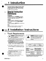
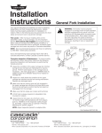
l
Service
Manual
30D QFM’”
Quick Fork Mount Push/Pull
Serial Numbers 677190 through 677192
a
Manual Number 678535
cascade”
Cascade
is a Registered Trademark
of Cascade
Corporation
l
QFM is a Trademark
of Cascade
Corporation
*
. .
t‘
Contents
Page Number
1
INTRODUCTION, Section 1 .................
INSTALLATION INSTRUCTIONS, Section 2 ... ,.l
1
Truck Requirements .......................
2
Installation. ..............................
2
Prior to installation ......................
3
Initial Installation ........................
5
Prior to Operation .......................
5
PERIODIC MAINTENANCE, Section 3. ........
6
TROUBLESHOOTING,
Section 4 .............
6
General Procedures .......................
6
Truck System Requirements ...............
6
Tools Required .........................
6
Get All the Facts ........................
7
Plumbing ...............................
7
Hosing Diagram ........................
7
Circuit Schematic .......................
8
Push/Pull Circuit ..........................
9
SERVICE, Section 5 .......................
9
Attachment Removal and Installation ..........
10
Faceplate and Linkage. ....................
10
Disassembly and Reassembly .............
.12
Link Service ..........................
.13
Hose Installation .......................
Valve...................................1
4
.14
Removal and Installation .................
.14
Disassembly and Service ................
.15
Cylinders. ..............................
Gripper Cylinder Removal and Installation .... 15
Push/Pull Cylinder Removal and Installation
.15
.16
Push/Pull Cylinder Adjustment ............
.17
General Cylinder Service Procedures. ......
.18
Gripper Cylinder Service .................
.18
Push/Pull Cylinder Service ...............
.19
Platens ................................
.19
Removal and Installation .................
.19
Inspection ............................
.20
SPECIFICATIONS, Section 6 ...............
Hydraulics...............................2
0
.20
Truck Carriage ..........................
.21
Torque Values ..........................
678535 Rev. 0
1 Introduction
Section
This manual provides the installation instructions, periodic
maintenance requirements, troubleshooting procedures
and service guides for 30D QFM TMQuick Fork Mount
Push/Pulls. Note that all specifications are shown in US
and (Metric) units where applicable.
1.1 Special Instruction
Definitions
A statement preceded by A WARNING is information
that should be acted upon to prevent bodily injury. A
WARNING is always inside a ruled box.
CAUTION
A statement preceded by CAUTION is information that
should be acted upon to prevent machine damage.
IMPORTANT
A statement preceded by IMPORTANT is information that
possesses special significance.
NOTE
A statement preceded by NOTE is information that is
handy to know and may make your job easier.
2 Installation Instructions
Section
2.1 Truck Requirements
0
A
A
WARNING: The QFM TMPush/Pull must be
mounted on standard forks to support the
load and the attachment.
0 Sideshifter Limitations: To avoid mounting interference, the Sideshifter components and cylinder must
not protrude in front of the carriage fork bars.
0 Fork Specifications: Forks up to 1.8 in. (4.5 cm)
thick and 40-46 in. (101-l 16 cm) long may be used.
Recommended fork length is 42 in. (106 cm) with bottom taper. The forks must be adjustable to 22.5-25.5
in. (57-64 cm) between the inner edges of the forks.
l
Truck carriage or Sideshifter carriage must conform to
ISO dimensional standard 2328, equivalent to Industrial Truck Association (ITA) dimensions shown at right.
0 Make sure the truck carriage is clean and the notches
are undamaged.
l
In order to conform to industry standard practice, the
hoses should be connected to the truck auxiliary valve
as indicated in the chart at right.
l
Truck Relief Valve Setting: 2300 psi (160 bar),
maximum.
l
Hydraulic flow: 4-10 GPM (15 L/min 38 L/min).
l
Recommended hose and fitting size: No. 6 with minimum fitting orifices of 3/8 in. (9.5 mm).
-f
R
A
WARNING: Rated capacity of the truck /
attachment combination is a responsibility
of the original truck manufacturer and
may be less than that shown on the
attachment nameplate. Consult the truck
nameplate.
iii
14.94 In (379.5 mm)
15.00 in. (381 .O mm)
I
Function, in
sequence of
location to
the operator
Attachment
movement
Motion of the operator’s
hand when actuating the
truck auxiliary control
I
Sideshift
when equipped)
Push/Pull *
678535
Rev. 0
*Trucks equipped with a three-function auxiliary control valve and
solenoid adaption require the control knob electrical button to be
depressed for operation of the push/pull function.
1
Section
2 Installation Instructions
2.2 Installation
A
2.24
Cascade THINLINE TM Hose
Reel and mast supply group
for QFM TM Push/Pull Operation.
WARNING: Rated capacity of the truck/
attachment combination is a responsibility
of the original truck manufacturer and
may be less than that shown on the
attachment nameplate. Consult the truck
nameplate.
Prior to Installation
The following preparation should be performed prior to
attachment installation.
The QFM M Push/Pull requires a mast hydraulic supply
group. If a Sideshifter is not installed and the truck is not
equipped with mast internal hose reeving, a hose reel will
be required. Refer to Form 673835 for THINLINE TMHose
Reel installation Instructions.
A
Trucks equipped with a Sideshifter and a single-function
auxiliary control valve will require conversion to two
function operation by installation of Solenoid Adaption Kit
674303. Refer to Form 674306 for installation instructions.
Solenoid Adaption electrical schematic shown below.
To utilize the attachment’s Quick Mount features, installation of hydraulic quick disconnect couplers is required.
Cascade Hydraulic Quick Disconnect Coupling Kit 671045
is recommended because of the couplers’ hydraulic efficiency. Refer to Form 671422 for installation instructions.
2
WARNING: The QFM TMPush/Pull must be
mounted on standard forks to support the
load and the attachment.
Sideshifter
Hose Reel
QFM” Push/Pull
Hose Reel
Cascade Hydraulic
quick Disconnect
Coupling Kit 671045
678535 Rev. 0
l
.]
Section
2.2-2
2 Installation Instructions
Initial installation
0
Attach a hoist rated at 2000 lbs. minimum through
the frame and faceplate as shown. Remove the
attachment from the shipping pallet. Pull out the
lower mounting hook locking pins and turn the lower
mounting hooks downward until they lock in position.
Place the attachment on the floor with a 2 x 4 under
the platen tips.
L
A
0
Adjust the truck forks to a measurement of 22.5-25.5
in. (57-64 cm) between the inner edges of the forks.
Engage fork detent pins in appropriate notches.
0
Position the truck carriage in the true vertical position. Lower the forks to the ground. Center the truck
carriage behind the attachment. Drive forward to
fully engage the truck upper carriage bar with the
attachment upper hooks. Raise the attachment 1-2 in.
(2-5 cm).
WARNING: The QFM TMPush/Pull must be
mounted on standard forks to support the
load and the attachment.
R
\
0
lower mounting
Hooks
2x4
Connect the attachment hoses to the truck hose terminal fittings or Quick Disconnect fittings. Route the
hoses to avoid interference with the mast.
.
Lower hooks must be
in the down position.
To Hose Reel
NOTE: Installation of Cascade Quick Disconnect
Hydraulic Coupler Kit 671045 is recommended.
-
quick
.
Disconnect
Couplings
676535 Rev. 0
II
2 Installation Instructions
Section
2.2-2
Initial
Installation
(cont.)
0
Disconnect the truck supply hoses from the attachment
push/pull valve fittings. Connect the hoses together
with a union fitting. Start the truck and actuate the
truck control valve in both directions for about 30
seconds to carry any debris in the supply group to the
truck tank and filter. On trucks equipped with solenoid
adaption, the control knob electrical button must be
pressed. Reinstall the hoses to the attachment.
0
Actuate the push/pull control valve to position the
faceplate out approximately 3/4 of its travel on the
platen. Raise the attachment to eye level to gain
access to the lower mounting hooks.
A
WARNING: The lower
mounting hooks are
not secured at this time. Use caution while
working near the raised attachment.
’ Lower Mounting Hooks
0
Loosen the mounting hook capscrews. Position hooks
down to end of adjustment slot. Pull out the lower
mounting hook locking pins. Rotate the hooks up and
lock in place. Adjust the hooks for 1/16 In. (1.5 mm)
clearance with the lower carriage bar. Tighten the cap
screws to a torque of 55-65 ft-lbs. (74-84 N-m). Make
sure the hooks swing down and lock properly for
attachment removal.
A
0
WARNING: The lower
hooks must be firmly
locked in the up position.
The inside spacing between the platens can be
adjusted to 4 in. or 10 in. (10 or 25 cm) as required.
Remove the platen capscrews and nuts. Move the
platens to line up with the other set of predrilled holes.
Install the capscrews and nuts. Tighten to a torque of
ft-lbs. (47-60 N-m).
35-45
Adjustable to
4 or 10 in.
(10 or 25 cm).
4
678535 Rev. 0
2 Installation Instructions
Section
Priorto operation
2.3-3
0
Operate the attachment through several complete
cycles to make sure all functions operate correctly.
l
Retract the faceplate and note that the gripper bar
closes fully before the faceplate retracts.
0 Extend the faceplate and note that the gripper bar
opens before the faceplate extends.
0 With the faceplate extended and the control valve
in neutral, the gripper bar should not drift down.
0
Check for external leaks at the hoses and fittings.
3 Periodic Maintenance
Section
3.1 1OO-HourMaintenance
Every time the lift truck is serviced or every 100 hours of
truck operation, whichever comes first, complete the following maintenance procedures.
0 Inspect the link rollers and related parts for sufficient
lubrication. If necessary, lubricate with Dubois FGG-2
food industry grease, Cascade part no. 669306.
13 Inspect the hoses mounted to the links. They should be
mounted securely and without hose droop. Check for
hose wear and kinking. Replace kinked or worn hoses.
Refer to Section 5.2-3.
3.2
IMPORTANT
After completing any service procedure, always test
each function through 5 complete cycles. First test
the attachment empty, then test each function with a
load to make sure the attachment operates correctly
before returning it to the job.
500-Hour Maintenance
After each 500 hours of lift truck operation, in addition to
the 100-hour maintenance procedures, perform the following procedures.
0 Inspect all bushings and thrust races at the pivot points
for excessive wear. Replace if. necessary.
13 Tighten the capscrews that secure the link pivot points
to a torque of 20-30 ft-lbs. (27-40 N-m).
q Inspect the bolts securing the gripper pad. Tighten if
necessary to a torque of 15-20 ft-lbs. (20-27 N-m).
0
A
WARNING: Tighten the platen capscrews to
a torque of 35-45 ft-lbs. (47-60 N-m).
0 Tighten the mounting hook capscrews to a torque of
55-65 ft.-lbs. (74-87 N-m).
3.3 1000-Hour
Maintenance
After each 1000 hours of lift truck operation, in addition to
the 100-hour and 500-hour maintenance procedures, perform the following procedure.
0 Replace all arm bushings and thrust races.
678535 Rev. 0
5
4 Troubleshooting
Section
4.1 General Procedures
WARNING: Before servicing any
hydraulic component, relieve pressure in
the system. Fully extend the faceplate,
turn the truck off, and open the truck
auxiliary valves several times in both
directions.
After completing any service procedure,
always test the function through several
cycles. First test the attachment empty,
then test the attachment with a load to
be sure it operates correctly before
returning it to the job.
Stay clear of the load while testing. Do
not raise the load more than 3 in.
(75 mm) off the floor while testing.
4.1-1 Truck System Requirements
0 The lift truck must supply sufficient hydraulic pressure to
handle the heaviest load. PRESSURE MUST NOT
EXCEED 2300 PSI (160 BAR).
0 Hydraulic flow: 4-10 GPM (15 L/min-38 L/min)
0 The truck hydraulic system must supply hydraulic oil to
the attachment that meets the specifications shown in
Section 6.1-l.
4.1-2
Tools Required
In addition to a normal selection of hand tools you will
need:
l
A pressure gauge capable of measuring pressure to
2500 psi (175 bar), Cascade part no. 671212.
0 An inline flow meter capable of measuring hydraulic
flow to 20 GPM (80 L/min), Cascade part no. 671447.
4.1-3 Get All the Facts Before You
Begin Working on the
Attachment
It is important that you gather all the facts regarding the
problem before you begin service procedures. The best
way is to talk with the operator. Ask for a complete
description of the malfunction. The following guidelines will
help you decide where to begin your troubleshooting
procedures.
0 Attachment will not pull load.
l
Faceplate will not extend or retract.
l
Faceplate operates slowly.
l
Gripper bar will not lower or raise.
l
Gripper bar is not sequenced
function.
l
Gripper bar will not hold the slip sheet when pulling
load onto platens.
with the push/pull
If you encounter one of these problems, refer to Section
4.3.
678535 Rev. 0
Section
0
4 Troubleshooting
4.2
Plumbing
4.2-l
Hosing Diagram
FACEPLATE RETRACT AND
GRIPPER BAR DOWN
Hose Reel
PRESSURE
-
RETURN
1
m.3:I*x.:.:<.>:...>,*,.
NOTE: For faceplate EXTEND.
reverse the shading shown.
Truck
Auxiliary
Valve
4.2-2
Circuit Schematic
Push/Pull
Cylinders
-
-yr
-LA
Gripper
Cylinders
L--Gripper Bar - -
Truck
Hydraulic
Pump
678535 Rev. 0
7
L
Section
4 Troubleshooting
*
4.3 Push/Pull Circuit
There are five potential problems that could affect
push/pull operation.
l
Physically jammed mechanism
l
Insufficient hydraulic flow and pressure
l
Worn or defective cylinder seals
0 Valve assembly malfunction
0 Kinked supply hoses
Before proceeding, determine whether the push function or
the pull function is at fault.
WARNING: Before removing any hoses,
relieve pressure that might be present in
open the truck auxiliary control valve(s)
several times in both directions.
Check the pressure delivered by the truck. Refer to the
truck service manual. The pressure must be within 100
psi (7 bar) of specified truck pressure. TRUCK PRESSURE
SHOULD BE 2000 PSI (138 BAR) MINIMUM AND 2300 PSI
(160 BAR) MAXIMUM, measured at the hose terminal.
Check the flow volume at the hose terminal. See Section
6.1-l for the recommended flow volumes.
Push
function
Gripper Bar will not raise 0 Physically jammed mechanism.
0 Kinked hoses.
Gripper Bar drifts down 0 Valve assembly check valve stuck in open position due
to contamination or damaged seals. Refer to Section 5.3-l.
l
Damaged seals in gripper cylinder. Refer to Section 5.4.
Gripper Bar raises but faceplate does not extend l
Valve assembly relief valve stuck in closed position due
to contamination or damaged seals. Refer to Section 5.3-l.
l
Valve assembly cartridge valve(s) factory set relief
pressures have been altered. Replace the cartridges.
Refer to Section 5.3-l.
Faceplate extends slowly l
Worn seals in push/pull or gripper cylinders. Refer to
Section 5.4.
PULL FUNCTION
Gripper Bar will not lower l
Physically jammed gripper mechanism.
l
Valve assembly check valve stuck in closed position due
to contamination or damaged seals. Refer to Section 5.3-l.
Gripper Bar lowers but faceplate does not retract l
Valve assembly check valve stuck in closed position
due to contamination or damaged seals. Refer to
Section 5.3-l.
l
Worn seals in push/pull cylinders. Refer to Section 5.4.
Gripper Bar does not hold slip sheet during faceplate
retract a Worn seals in gripper cylinders. Refer to Section 5.4.
0 Damaged gripper pad or jaw.
8
678535 Rev. 0
5 Service
Section
0
5.1 Attachment Removal
and Installation
0
Extend the faceplate to approximately 3/4 of its travel
on the platen. Position the attachment 2 ft. (60 cm) off
the ground with the mast in the true vertical position.
0
Pull out the lower hook locking pins. Swing the lower
mounting hooks down and lock in the disengaged
position.
To Hose Reel
0
rli
I
Disconnect the quick disconnect hydraulic couplers at
the truck carriage.
WARNING: Before removing any hoses,
relieve pressure that might be present in
open the truck auxiliary control valve(s)
several times in both directions.
0
Place a 2 x 4 (15 in. long) on the floor under the
platen tips. Lower the attachment to the ground. Back
the truck away from the attachment.
0
For installation, reverse the above procedures.
A
WARNING: The QFM TM Push/Pull must be
mounted on standard forks to support the load
and the attachment.
2x4
678535 Rev. 0
lower hooks must be
in the down position.
9
5 Service
Section
5.2 Faceplate and Linkage
5.2-l Disassembly and Reassembly
0
/a/
10
Fully extend the faceplate. Attach an overhead hoist
chain to the top of the faceplate. Take up slack in the
chain.
WARNING: Before removing any hoses,
relieve pressure that might be present in
the hydraulic system. With the truck off,
open the truck auxiliary control valve(s)
several times in both directions.
0
Disconnect the hoses from the faceplate valve. Remove
the hose clamps from the faceplate and links. For
reassembly, tighten the hose clamp capscrews to a
torque of 4-5 ft.-lbs. (5-7 N-m).
0
Remove the capscrews from the inner secondary link
lower pivot pins. Remove the pivot pins, For reassembly, tighten the capscrew to a torque of 8-10 ft-lbs.
(10-13 N-m).
0
Remove the faceplate with the hoist. Tilt the faceplate
to disengage the outer secondary link rollers from the
faceplate channels. Set the faceplate face down.
0
Remove the capscrew from the left inner primary link
at the cylinder rod end pivot point. For reassembly,
tighten the capscrew to a torque of 6-7 ft.-lbs. (8-9
N-m).
0
Remove the cylinder rod end pivot pin.
@
Remove the roll pins from the inner primary link lower
pivot pins. Remove the pivot pins.
0
Remove the linkage assembly from the frame by lifting
with an overhead hoist. Tilt the linkage assembly to
disengage the outer primary link rollers from the frame
channels.
0
Remove the capscrews and caps from both inner
primary/secondary link upper pivot points. For
reassembly, tighten the capscrews to a torque of
20-30 ft.-lbs. (27-40 N-m).
@
Remove the upper pivot pin and hose guide tube.
Note location of the thrust races during pivot pin
removal.
@
Remove the capscrews and caps from the primary link
center pivot points.
@
Remove the capscrews and caps from both outer
primary/secondary link lower pivot points. For
reassembly, tighten the capscrews to a torque of
20-30 ft.-lbs. (27-40 N-m).
@
Remove the capscrews from both outer secondary link
center pivot points. For reassembly, tighten the
capscrews to a torque of 6-7 ft.-lbs. (8-9 N-m).
@
Remove the center pivot pin and tube. Note location
of the thrust races during pivot pin removal.
@
For reassembly, reverse the above procedures.
678535 Rev. 0
Section
a
5.2-l
5 Service
Disassembly and Reassembly
(cant .)
Faceplate
, I_
1; Link Rollers
678535 Rev. 0
11
5 Service
Section
5.2-2 Link Service
Remove the links from the attachment as described in Section 5.2-l.
0
Remove the bushings from the links using a bushing
driver.
0 If you do not have bushing drivers, a tool as shown
at right can be fabricated for bushing removal.
0
Inspect the cam followers for excessive wear or damage. If flat spots or cracks are visible on the cam followers, they should be replaced. Cam followers with
roughness or noticeable restriction to turning should
be replaced.
@
For reassembly, reverse the above procedures except
as follows:
l
Bushing drivers must be used to press new bushings into the links.
0 If cam followers are being replaced, the nut should
be tightened to a torque of 130-150 ft-lbs. (175-200
N-m).
L.JJ,”
l- 50”
Ll.247”
1.240”
Bushing Driver
Material: AISI - 1015
(Hot Roller Mild Steel)
0 The small plug supplied with each replacement
cam follower must be installed in the shaft end
hole.
Secondary
Link
.990”
Use bushing drivers to
remove and replace
all link bushings.
Cam Follower
Install small plug.
12
678535 Rev. 0
Section
5.2-3
5 Service
Hose
Installation
The attachment hoses must be installed as described
below for correct hydraulic operation and tracking of the
hoses with the arms during faceplate extension and retraction. Installing replacement hoses other than Cascade hose
is not recommended.
0
Connect the hoses to the valve and push/pull cylinder.
0
Route hoses through the arms to the faceplate. Connect hoses to the gripper cylinder lubes as shown.
0
Install arm hose clamps to hose. Install hose clamp
capscrews and tighten to a torque of 4-5 ft.-lbs. (5-7
N-m).
0
Arrange hoses as shown below. Install cable ties at
the locations shown.
Hose d
80.5 in.
(3204 cm)
View from Driver’s Seat
Valve
e
Hose 0-1
0
Hose
Hose
0,
Cable Ties
A3
Hose d
80.5 in.
b
Hose
(-)204 cm
678535 Rev. 0
13
5 Service
Section
5.3
Valve
5.3-l Removal and Installation
0
Fully extend the faceplate.
A
5.3-2
WARNING: Before removing any hoses,
relieve pressure in the hydraulic system.
Turn the truck off, then open the truck
auxiliary control valve(s) several times in
both directions.
@
Disconnect,tag and plug the hoses from the valve
fittings.
0
Remove the two capscrews and nuts securing the
valve. For reassembly, tighten the capscrews to a
torque of 4-5 ft-lbs. (5-7 N-m).
Disassembly and
IMPORTANT:
service
Service the valve in a clean work area.
0
Remove the valve from the attachment as described in
Section 5.3-l.
0
Remove fittings and plugs.
0
Remove the valve cartridges.
0
Clean all parts with kerosene or solvent. Check for
contamination in pilot holes, etc.
0
For reassembly, reverse the above procedures except
as follows:
0 Lubricate the check valve cartridges with STP 01
petroleum jelly prior to reassembly.
0 Tighten all fittings and cartridges to a torque of
10-15 ft.-lbs. (13-19 N-m).
Back-up Ring -
Cartridge
Part No. 659056 Part No. 677124
LL-
O-Ring
’
F
))
back-up ring,
O-Ring
Service Kit
Part No. 669597
5
Service Kit
Part No. 667516
part No. 677125
678535 Rev. 0
5 Service
Section
t
0
5.4
Cylinders
5.4-l Gripper Cylinder Removal
and Installation
0
Fully extend the faceplate.
WARNING: Before removing any tubes,
relieve pressure that might be present in
the hydraulic system. With the truck off
open the truck auxiliary control valve(s)
several times in both directions.
a
0
0
l
5.4-2
Disconnect the tube fittings from the cylinder fittings.
Remove the cylinder anchor roll pins.
Installation is a reverse of the above procedures.
Push/Pull Cylinder
Removal and Installation
0
Fully extend the faceplate.
A
WARNING: Before removing any hoses,
relieve pressure that might be present in
the hydraulic system. With the truck off,
open the truck auxiliary control valve(s)
several times in both directions.
0
Disconnect, tag and plug the hoses shown from the
cylinder fittings.
0
Disconnect the tubes from the cylinder fittings.
0
Remove the lower pivot pin retaining capscrew from
the L.H. inner primary link. Remove the lower pivot
pin. For reassembly, tighten the retaining capscrew to
a torque of 6-7 ft.-lbs. (8-9 N-m). Mark the cylinders
R.H. and L.H. for reassembly.
0
Remove the upper pivot pin retaining capscrew and
eyebolt. Remove the upper pivot pin. For reassembly,
tighten the capscrew to a torque of 4-5 ft-lbs. (5-7
N-m).
0
After reassembly, adjust the cylinder rod length as
described in Section 5.4-3.
678535 Rev. 0
15
.
5 Service
Section
5.4-3 Push/Pull Cylinder Adjustment
0
Position the faceplate 1 or 2 in. short of full extension.
Turn the cylinder lock nuts clockwise to the end of
their travel. Turn the cylinder rods. using the wrench
flats, clockwise to the end of their travel.
@
Fully retract the faceplate.
l
The faceplate should retract smoothly without
restriction or binding of the arms.
0 The push/pull cylinder should bottom internally as
the faceplate makes initial contact with the frame.
Adjust both cylinder rods equal amounts as
required.
l
0
0
II
t-l
If the faceplate does not retract parallel with the
frame, adjust one cylinder rod as required.
l-
Fully extend the faceplate. The extension of the
faceplate should be 5O .5 in. (127 1 cm).
After all adjustments have been made, hold each cylinder
rod in position and tighten the lock nuts against
the rods to a torque of 100-150 ft.-lbs. (135-200 N-m).
- -u
-
Wrench
Flats
Nuts
16
lIlll
Rods
678535 Rev. 0
5 Service
Section
0
5.4-4 General Cylinder Service
Procedures
Cylinder Disassembly
Use a pin-type spanner wrench to remove push/pull
cylinder retainers.
When servicing a cylinder, clamp it in a soft-jawed vise
as shown. Never clamp the cylinder shell of the
cylinder rod sealing area in a vise.
To remove the seal from a piston or a retainer, put the
piston or retainer in a soft-jawed vise. Pry the seal up
with a blunt tool such as a screwdriver, then cut the
seal to remove it. Be careful not to scratch the seal
Clamp cylinder in
soft-jawed vise.
CAUTION:
Do not scratch
PI
Gripper Cylinder
Clamp cylinder in
soft-jawed vise.
I
I
Cylinder Inspection
l
Inspect the rod, piston and retainer for nicks and burrs.
If deeply gouged, replace the part. Minor nicks and
burrs can be removed with an emery cloth.
NOTE: A minor nick is one that will not cause a bypass
of oil when the cylinder is operating.
l
Inspect the inside of the cylinder shell and remove any
minor nicks and burrs with a butterfly hone. Replace the
cylinder shell if it is deeply gouged.
Cylinder Reassembly
l
Lubricate all new seals with STP before installing.
l
To install a new seal on a piston or retainer, hook one
side of the seal in the groove and push it over the piston or retainer.
NOTE: Polishing the chamfer angle will allow the seal to
slide into the groove much easier.
l
Note the direction of U-cup seals. If they are installed
backwards, the seals will not seal properly. Refer to the
illustration of the cylinder you are servicing on page 18.
l
Reassemble the rod assembly by sliding the retainer on
first, then the piston assembly. Install and tighten the
piston retaining nut before sliding the rod assembly into
the shell.
l
Observe all torque values as shown in the appropriate
illustration.
678535 Rev. 0
Install new seals as shown.
17
5 Service
Section
5.4-5 Gripper Cylinder Service
5.4-6
0
Remove the snap ring.
0
Remove the retainer ring by first tapping the retainer
into the shell bore. Then place a screwdriver on one
side of the ring and tap the screwdriver with a hammer. Do not gouge the shell bore with the screwdriver.
The retainer ring should compress at the split and turn
sideways as shown at right. Pull out the ring.
0
Pull the rod assembly out of the shell.
0
Remove the nut securing the piston to the rod For
reassembly, tighten the nut to a torque of 40-45 ft.-lbs.
(54-61 N-m).
0
Slide the piston and retainer off the rod.
0
Remove and replace all seals.
@
Perform the inspection and reassembly
procedures listed in Section 5.4-4.
Retainer
Ring
0
4!l=-=
Push/Pull Cylinder Service
Read the General Service Procedures, Section 5.4-4 before
proceeding.
) Use a pin-type spanner wrench to remove the retainer.
For reassembly, tighten the retainer to a torque of
300-350 ft-lbs. (405-475 N-m).
@
Pull the rod assembly out of the shell.
0
Remove the nut securing the piston to the rod.
0
Slide the piston and retainer from the rod.
0
Remove and replace all seals.
0
Remove and replace the cylinder rod and base end
bushings.
l
18
If you do not have bushing drivers, a tool as shown in
Section 5.2-2 can be fabricated for bushing removal.
678535 Rev. 0
5 Service
Section
5.5 Platens
5.5-l Removal and Installation
0
Fully retract the faceplate. Lower the attachment to 1
ft. above the floor.
0
Remove the capscrews and nuts. For reassembly,
tighten the capscrews to a torque of 35-45 ft.-lbs.
(47-60 N-m).
0
Reassembly is a reverse of the above procedures
except as follows:
0 The inside spacing between the platens can be
adjusted to 4 in. (5.4 cm) or 10 in. (13.5 cm). Move
the platens to line up with the other set of predrilled
holes. Reinstall the capscrews and nuts.
5.5-2
Inspection
0
Check the platen tips for nicks. Flatten out nicks with a
hammer and smooth the edges with a file or grinder.
@
An application of wax or paraffin on the top of the
platens will reduce friction between the platens and
slip sheets. Use steel wool to remove excess wax.
Spacing adjustable to
4 in. (5.4 cm) or
10 in. (13.5 cm).
678535 Rev. 0
19
6 Specifications
Section
6.1-l
Hydraulics
I
Hydraulic Specifications
I
30D
I
Pressure-Maximum
2300 PSI
(160 bar)
Flow--Minimum@
)
Supply Hose & Fitting Size
Minimum Orifice Size
g
w
No. 6
318 in. (9.5 mm)
Flow less than minimum will result in slow faceplate speed.
Flow greater than maximum can result in excessive faceplate speed,
reduced system performance and short hydraulic system life.
Hydraulic Oil-Cascade
attachments are compatible with
SAE 10 W petroleum base oil per Mil. Spec. MIL-0-5606 or
MIL-L-2104B.
Use of synthetic or aqueous base hydraulic oil is not
recommended. Contact Cascade if fire-resistant hydraulic
oil must be used.
In order to conform to industry standard practice, the
hoses should be connected to the truck auxiliary valve as
indicated by the chart.
*Trucks equipped with a single-function auxiliary control valve and
solenoid adaption require the control knob electrical button to be
depressed for operation of the push/pull function.
6.1-2
Truck Carriage
Truck carriage must conform to ISO dimensional standard
2328, equivalent to Industrial Truck Association (ITA)
dimensions shown.
Make sure the truck carriage is clean and the notches are
undamaged.
14.94 in. (379.5 mm)
20
15.00 in. (381.0 mm)
678535 Rev. 0
Section
6 Specifications
Torque Values
Note that all specifications are shown in US and (Metric)
units where applicable.
Not Shown
Valve fittings-l O-15 ft.-lbs. m).
(13-19 N-m).
Cylinder retainers and piston nuts-see Sections 5.4-5 and
5.4-6.
Ref.
No.
Torque Values
Fastener Thread Size
Ft.-Lbs.
(N-m
1
1/4 NC
4-5
5-7
2
1/4 NC
6-7
8-9
3
7/8 NF
130-150
(175200)
4
1/4 NC
4-5
5-7
5
3/8 NC
20-30
(27-40)
6
1/2 NC
35-45
(47-60)
7
1/2 NC
55-65
(74-87)
8
1/4 NC
6-7
(8-9)
9
1-1/4 NF
100-150
(135-200)
1
678535 Rev. 0
15-20
1
(20-27)
21
AMERICAS
Cascade Corporation
U.S. Headquarters
2201 NE 201st
Fairview, OR 97024-9718
Tel: 800-CASCADE (227-2233)
Fax: 888-329-8207
Cascade Canada Inc.
5570 Timberlea Blvd.
Mississauga, Ontario
Canada L4W-4M6
Tel: 905-629-7777
Fax: 905-629-7785
Cascade do Brasil
Rua João Guerra, 134
Macuco, Santos - SP
Brasil 11015-130
Tel: 55-13-2105-8800
Fax: 55-13-2105-8899
EUROPE-AFRICA
Cascade Italia S.R.L.
European Headquarters
Via Dell’Artigianato 1
37030 Vago di Lavagno (VR)
Italy
Tel: 39-045-8989111
Fax: 39-045-8989160
Cascade (Africa) Pty. Ltd.
PO Box 625, Isando 1600
60A Steel Road
Sparton, Kempton Park
South Africa
Tel: 27-11-975-9240
Fax: 27-11-394-1147
ASIA-PACIFIC
Cascade Japan Ltd.
2-23, 2-Chome,
Kukuchi Nishimachi
Amagasaki, Hyogo
Japan, 661-0978
Tel: 81-6-6420-9771
Fax: 81-6-6420-9777
Cascade Korea
121B 9L Namdong Ind.
Complex, 691-8 Gojan-Dong
Namdong-Ku
Inchon, Korea
Tel: +82-32-821-2051
Fax: +82-32-821-2055
Cascade-Xiamen
No. 668 Yangguang Rd.
Xinyang Industrial Zone
Haicang, Xiamen City
Fujian Province
P.R. China 361026
Tel: 86-592-651-2500
Fax: 86-592-651-2571
Cascade Australia Pty. Ltd.
1445 Ipswich Road
Rocklea, QLD 4107
Australia
Tel: 1-800-227-223
Fax: +61 7 3373-7333
Cascade New Zealand
15 Ra Ora Drive
East Tamaki, Auckland
New Zealand
Tel: +64-9-273-9136
Fax: +64-9-273-9137
Sunstream Industries
Pte. Ltd.
18 Tuas South Street 5
Singapore 637796
Tel: +65-6795-7555
Fax: +65-6863-1368
Cascade India Material
Handling Private Limited
No 34, Global Trade Centre
1/1 Rambaugh Colony
Lal Bahadur Shastri Road,
Navi Peth, Pune 411 030
(Maharashtra) India
Phone: +91 020 2432 5490
Fax: +91 020 2433 0881