1
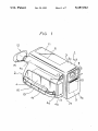
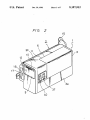
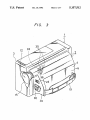
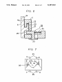
llllllllllllllIllIlllllllllIlllllllllIlllllllllllllllllllllllllllllllllllll
.
USOO5157512A
United States Patent n9]
[11] Patent Number:
Inada et al.
[45]
[54]
VIDEO TAPE RECORDER HAVING
BUILT-IN CAMERA DETACHABLE HAND
[56]
1
GRIP MEMBER
[75]
Inventors:
[73] Assignee:
Date of Patent:
[63]
9/ 1984
Shinsaku Inada; Eiji Ohshima, both
4,470,077
4,499,504 2/1985 Edakubo et a1.
Masayoshi Morikawa, Tokyo, 31] of
4,507,689
Japan
4,530,015
7/1985 Yanagida et a1. ..
4,531,159
7/1985
Sony Corporation, Tokyo, Japan
Takubo et a1. . . . . .
358/906 X
. . . .. 358/906 X
358/906 X
. . . .. 358/906 X
Kimura
358/906 X
. .. . . . .
. . . ..
358/906X
Takubo ......................... .. 358/906 X
OTHER PUBLICATIONS
Sony Service Manual, CCD-V8, Mar. 1985, Cover and
p. 146.
Primary Examiner—Wayne R. Young
Attorney, Agent, or Firm-Hill, Van Santen, Steadman &
Simpson
Foreign Application Priority Data
Japan
Japan
Japan
Japan
10/1985
4,625,243 11/1986
Related US. Application Data
Continuation of Ser. No. 587,537, Sep. 21, 1990, aban
27, 1985 [JP]
27, 1985 [JP]
27, 1985 [JP]
Kozuki et al. . . . . . .
. . . .. 358/906 X
4,539,601 9/1985 Komine
Aug. 26, 1991
27, 1985 [JP]
3/1985
Kornine . . . . , . . . . .
4,571,627 2/1986 Stempeck .............. .. 358/906 x
4,589,747 5/1986 Nakayama et a1.
354/288 X
Ser. No. 866,971, May 27, 1986, abandoned.
May
May
May
May
I
9/1974 Ferrari .......................... .. 358/906 X
of Tokyo; Hideaki I0, Kanagawa;
doned, which is a continuation of Ser. No. 193,138,
May 6, 1988, abandoned, which is a continuation of
[30]
References Cited
U.S. PATENT DOCUMENTS
APPI- N0-= 751,650
[22] Filed:
Oct. 20, 1992
3,833,758
4,547,815
[21]
5,157,512
........................... .. 60-78896[U]
[57]
........................... .. 60-78897[U]
........................... .. 60-78898[U]
........................... .. 60-78899[U]
A combination video tape recorder and camera includes
a main body having a video tape recorder and a televi
sion camera, and a separable hand grip secureable to a
side wall of the main body. The hand grip carries a view
?nder for the camera and a battery for supplying opera
tional power to the video tape recorder and the televi
[51]
[52]
Int. Cl.5 ........................................... .. H04N 5/782
C1. .................................. .. 358/335; 358/906;
[58]
Field of Search ..................... .. 358/335, 906, 909;
360/331
ABSTRACT
sion camera.
360/6, 33.1; 369/53; 354/288 A-288 F, 288 H,
288 M, 288 P, 288 V
12 Claims, 7 Drawing Sheets
US. Patent
Oct. 20, 1992
FIG.
Sheet 1 of 7
7
5,157,512
US. Patent
Oct. 20, 1992
FIG.
Sheet 2 of 7
2
5,157,512
US. Patent
Oct. 20, 1992
FIG; 3
Sheet 3 of 7
5,157,512
US. Patent
Oct. 20, 1992
shee't 4 of 7
5,157,512
US. Patent
Oct. 20, 1992
Sheet 5 of 7
5,157,512 '
US. Patent
Oct. 20, 1992
FIG. 6
25-“
Sheet 6 of 7
5,157,512
US. Patent
Oct. 20, 1992
Sheet 7 of 7
5,157,512
1
5,157,512
2
OBJECTS AND SUMMARY OF THE
INVENTION
VIDEO TAPE RECORDER HAVING BUILT-IN
CAMERA DETACI-IABLE HAND GRIP MEMBER
Accordingly, it is a general object of this invention to
This is a continuation of application Ser. No. 587,537, 5 provide a video tape recorder having a built-in camera.
?led Sep. 21, 1990, which is a continuation of applica
tion Ser. No. 193,138, ?led May 6, 1988, which is a
continuation of application Ser. No. 866,971, ?led May
An object of this invention is to provide a video tape ,
recorder having a built-in camera in which a main body
section and a hand grip section are easily detachable
from each other so that upon carrying, the overall
27, 1986, all now abandoned.
10 thickness of the built-in camera type video tape re
BACKGROUND OF THE INVENTION
corder can be reduced and thereby the built-in camera
type video tape recorder can be easily kept in a thin case
1. Field of the Invention
or the like and made suitable for portable use.
The present invention relates generally to a video
Another object of this invention is to provide a video
tape recorder with a camera and more particularly is
tape recorder having a built-in camera in which a view
directed to a video tape recorder having a built-in cam
?nder and a battery are incorporated in a hand grip
era.
section and the main body section and the hand grip
2. Description of the Prior Art
section are separable at their side walls.
In a typical home video recorder having a built-in
A further object of this invention is to provide a
video camera, the user generally holds a hand grip
video
tape recorder having a built-in camera in which
portion of this built-in camera type video tape recorder
the status of the various operational elements in the
with his right hand while operating the camera to take
main body section can be optically displayed by an
video images.
optical type status indication section provided at the
In prior art video tape recorders having a built-in
camera, the hand grip portion is provided on a side wall 25 face, in the view ?nder area, and in which a hand grip
section is detachable from a main body section.
of the video tape recorder. This causes the overall
A still further object of this invention is to provide a
thickness of the video tape recorder to be relatively
video
tape recorder having a built-in camera, in which
large. As a result, when the user carries this video tape
a light guide section is mounted on a face in which a
recorder having a built-in camera in its non-operational
hand grip section is detachable from a main body sec
mode, this video tape recorder can not be put into a
tion, whereby‘ the optical display of an optical type
carrying case such as an attaché case or the like that is
status indication section is carried out within a view
relatively thin. Instead, the user has to carry such a
video tape recorder in a larger, special case, which is
generally unwieldy and often identi?able by others as a
camera case.
?nder incorporated in the hand grip section.
According to one aspect of the present invention,
35 there is provided a video tape recorder having a built-in
In the conventional built-in camera type video tape
recorder, a television camera section, a video tape re
corder section and a view ?nder section are substan
tially formed in combination as a single unit. Therefore, 40
the operational modes or status of the television camera
section and the video tape recorder section can easily be
displayed in an optical or electronic type view ?nder.
When a built-in camera type video tape recorder is
camera comprising:
a) a main body having a video tape recorder and a
television camera; and
b) a hand grip separably mounted on a side wall of
said main body, said hand grip carying a view
?nder and a battery for supplying operational
power to said video tape recorder and said televi
sion camera.
These and other objects, features and advantages of
designed to be small in size and hence easily portable, if 45 the present invention will become apparent from the
the television camera section and the video tape re
corder section are preferably formed into a combination
form as a main body, and a hand grip is formed to in
clude therein an optical type view ?nder and a battery,
if both the main body and the hand grip section are
following detailed description of the preferred embodi
ment taken in conjunction with the accompanying
drawings, throughout which like reference numerals
designate like elements and parts.
coupled together to take a video picture, the problem
BRIEF DESCRIPTION OF THE DRAWINGS
arises that the operational status of the television cam
era section and the video tape recorder section cannot
FIG. 1 is a perspective view of an embodiment of a
vided on the main body and the hand grip section so as
to be contacted with one another when both the main
of the video tape recorder having a built-in camera
according to the present invention, seen from its left
body and the hand grip are coupled together, it be
comes possible to display the operational status of the
front direction;
video tape recorder having a built-in camera according
be optically displayed within the optical type view 55 to the present invention, seen from its right-front direc
?nder.
tion;
Of course, if a number of electrical contacts are pro
FIG. 2 is a like perspective view of the embodiment
television camera section and the video tape recorder
FIG. 3 is a perspective view of the embodiment of the
video tape recorder having a built-in camera according
to the present invention, seen from its right-rear direc
section using light emission elements such as LEDs
(light emission diode) may be located within the optical
tion;
FIG. 4 is a perspective view of its main body seen
view ?nder. However, in this case, a further problem 65
occurs in that the electrical contacts will easily malfunc
from its right-rear direction;
tion, thus making this built in camera type video tape
recorder unreliable.
FIG. 5 is a perspective view of its hand grip section
seen from its left-rear direction;
3
5,157,512
4
A rechargeable battery 16 is incorporated within the
FIG. 6 is a partly sectioned view showing the state
that the main body and the hand grip are coupled with
hand grip-housing 4 so as to be freely‘ replaceable. An
each other;
opening 17 is formed through the front wall 4a of the
FIG. 7 is a diagram used to explain the status of an
optical type view ?nder as seen by a user;
FIG. 8 is a schematic perspective view showing a
hand grip housing 4 .to permit replacement of recharge
able battery 16. When the rechargeable battery is taken
relationship between a dust-proof cover and a lens of
out through the opening 17, the opening 17 may be
closed by a lid 18 (see FIG. 2). When the rechargeable
the television camera section; and
FIG. 9 is a circuit diagram showing a control circuit
that controls a micro-computer used in the invention.
battery 16 is inserted into the hand grip housing 4
through the opening 17, the lid 18 is opened with the tip
end of the rechargeable battery 16 and pushed back
DESCRIPTION OF THE PREFERRED
EMBODIMENT
the hand grip housing 4, the lid 18 automatically closes
inside. When the rechargeable battery 16 is taken out of
the opening 17. FIG. 2 illustrates the lid 18 in the midst
of its rising and falling movement. Further, a strap 19 is
An embodiment of a video tape recorder having a
built-in camera according to the present invention will 5 attached to the hand grip housing 4 in opposing relation
to the right side wall 4]". The user can hold the hand grip
hereinafter be described with reference to the attached
drawings.
Referring to FIG. 1 through FIG. 3, the video tape
recorder having a built-in camera according to this
embodiment is formed of a main body 1 and a hand grip
2 which are separable. Casings or housings 3 and 4 of
the main body 1 and the hand grip 2 are all made of
housing 4 with his right hand, which in turn is held
between the strap 19 and the hand grip housing 4.
The right side wall 3f of the main body housing 3 and
the left side wall 4e of the hand grip housing 4 are
formed as coupled side walls which are secured to each
other. On these walls 3f and 4e there are provided cou
synthetic resin. The main body housing 3 is formed
pling means, respectively. This will be described with
substantially as a rectangular solid shape and also the
hand grip housing 4 is formed substantially as a rectan
reference to FIGS. 4 and 5.
Referring to FIGS. 4 and 5, hooks 20 each being of an
L-shape are provided on the right side wall 3f of the
main body housing 3 at a plurality of places (four places
housing 4 is curved from its upper wall 4c through its
in the illustrated example), each of the hooks 20 facing,
right side wall 4f to its lower wall 4d so as to ?t the palm
or
opening the front side of the main body housing 30.
of the right hand of a user.
30
On the other hand, through the left side wall 4e of hand
A television (TV) camera section 5 and a video tape
grip housing 4, there are formed four recess portions 21
recorder (VTR) section 6 are incorporated in the main
in opposing relation to the above-mentioned four hooks
body housing 3, respectively. Further, a lens window
20. Further, in association with these recess portions 21,
frame 47 is ?xed to a lens window opening 8 of a rectan
there are respectively formed engaging recesses 22
gular shape formed through the upper portion of a front
which are extended to the front side of the hand grip
wall 30 of the main body housing 3. An objective lens 7
gular solid shape. In this case, however, the hand grip
of the TV camera section 5 faces to the outside through
the window frame 47 attached to the lens window open
ing 8. A dust-proof cover 9 is attached to the rear side
of the front wall 30 through appropriate attaching
means so as to be slidable in the vertical direction be
tween the front wall 3a and this window frame 47. The
upper end edge of this dust-proof cover 9 protrudes
slightly beyond the window opening 8 of the front wall
30 and thereby forms a knob 10 of the dust-proof cover
9. The cover 9 can be maintained in a ratchet detent
fashion so that it will be held in an open state as shown
in FIG. 1 or in the closed state as shown in FIG. 2.
A lid 11 having the same con?guration and shape as
a part of the main body housing 3 is attached to the main
body housing 3 from its upper wall 30 to its left side wall
3e. The lid 11 is made freely rotatable relative to the
main body housing 3 with its lower edge as a hinge.
When the lid 11 is set in the opened state, a video tape
cassette (not shown) is detachably loaded on a cassette
compartment portion (not shown) of the VTR section
6.
housing 4 within the same.
When the respective hooks 20 of the main body hous
ing 3 are engaged with the respective concave portions
21 of the hand grip housing 4, the right side wall 3f of
the main body housing 3 and the left side wall 4e of the
hand grip housing 4 are closely contacted with each
other. Under this state, if the main body housing 3 is slid
forward relative to the hand grip housing 4, the tip ends
of the respective hooks 20 are inserted into the engaging
recesses 22 formed within the respective portions 21
and the main body housing 3 and the hand grip housing
4 are coupled to each other, namely, the main body 1
and the hand grip 2 are coupled with each other.
In order to lock the main body 1 and the hand grip 2
in the coupled state locking means are provided.‘ As
. shown in FIGS. 3 and 6, a lever 23 which is slidable in
the right and left direction is attached to the rear wall 4b
of the hand grip housing 4. As shown in FIG. 6, this
lever 23 is slidably biased to the side of the main body
housing 3 by a spring 24 and the tip end of an engaging
piece member 25 connected to the lever 23 projects into
the concave portion 21 to prevent removal of the hook.
In the hand grip section 2, an optical type view ?nder
During the coupling of the main body housing 3 with
12 is incorporated in the upper portion of the hand grip
housing 4. An objective lens 13 of the optical view 60 the hand grip housing 4, when the hooks 20 are entered
into the recess portions 21, the engaging piece member
?nder 12 faces forwardly through a window opening 14
25 is moved backward against the biasing force of the
that is formed through the upper portion of the front
spring 24. When, as shown in FIG. 6, the hooks 20 are
once entered into the engaging recess portions 22, the
grip housing 4, there is attached a so-called eye cup 15
made of resilient material. In this case, this optical type 65 engaging piece member 25 is positioned in the recess
portion 21 and thereby its associated hook 20 is locked.
view ?nder 12 is completely independent of the optical
It is suf?cient that such locking means 26 is provided
system of the objective lens 7 of the television camera
within at least one recess portion 21.
section 5.
wall 4a. To the upper end of a rear wall 4b of the hand
5
5,157,512
6
tive operational status are designated particularly by
In the condition shown in FIG. 6, when the lever 23
is slid in the opposite direction to the main body housing
3 against the biasing force of the spring 24, the main
reference numerals a to d.
The end face a of the light guide tube is lit when the
color temperature is low such as when a picture is taken
body housing 3 can be moved backward relative to the
in the room and so on. In this case, it is sufficient that a
color ?lter within the optical system of the TV camera ,
hand grip housing 4, and the main body housing 3 and
the hand grip housing 4 can be separated from each
other.
section 5 in the main body 1 is changed to proper ?lter.
A switching lever 37 shown in FIG. 2 is provided for
such switching and this switching lever 37 is slidably
On the connection side wall, that is, right side wall 3f
' of the main body housing 3, there are formed a plurality
of electrical contacts 27 made of a metal plate (see FIG. 0 moved up and down.
When the end face b is lit, this indicates that the video
4), while on the left side wall 4e of the hand grip hous
tape recorder and so on are in standby mode. That is,
ing 4, there are formed a plurality of electrical contacts
this end face b is lit by pushing the above-mentioned
28 made of conductive pins in opposing relation to the
push
button 30 once. When this push button 30 is
respective contacts 27 (see FIG. 5). Accordingly, when
the main body housing 3 and the hand grip housing 4 15 pushed once more, the end face b becomes unlighted
are connected with each other as set forth above, the
respective contacts 27 and 28 are contacted electrically
so that from the rechargeable battery 16 located within
the hand grip housing 4, a power current may ?ow to
the television camera section 5 and the VTR section 6 in 20
the main body housing 3. Further, a push switch or push
button 30 for a trigger type switch is mounted on the
rear wall 4b of the hand grip housing 4. The signal
generated by operating this push buttom 30 is supplied
through one of the above-mentioned contacts 27 and 28
to the main body 1. In pratice, when this push button 30
is pushed initially, the video tape recorder and so on are
placed in the standby mode, while when it is pushed a
second time, the magnetic tape is transported and the
and the end face c is lit to indicate that the video tape.
recorder and so on are set in the operation mode (in the
recording mode). The end face (1 indicates a status in
which the amount of light is in suf?cient. In this case,
the lack of light amount can be made up for by the use
of lighting equipment. Since means for making the re
spective light emission elements of the operational sta
tus indicating section 31 become lighted, to thereby
indicate the above-mentioned operational status of the
S TV camera section 5 and the VTR section 6 within the
main body 1, is well known in the prior art, the detailed
explanation therefor will not be made. Alternatively, it
is, of course, possible to employ light emission elements
of different colors.
The TV camera section 5 in the main body 1 may
recording is carried out.
As shown, an operational status indicating section 31
formed of a plurality of (e.g., four in the illustrated
example) light emission elements are mounted on the
switchably take three positions, namely: wide angle lens
mode, standard lens mode, and telephoto lens mode, by
right side wall 3f of the main body housing 3 for cooper
peripheral surface of a cylinder 38 of the objective lens
7, there is engaged a protrusion (not shown) that ex
ation with a light guide 34 formed on the member 4 at
the position facing the indicating section 31, upon as
sembly.
moving the objective lens back and forth. As shown in
FIG. 8, into a helical groove 39 formed on the outer
tends from the inner surface of a ?xed cylinder (not
shown) which surrounds the cylinder 38 and which
Speci?cally, in opposing relation to the respective
guides the same back and forth therealong. On the other
light emission elements of the operational status indicat 40 hand, as shown in FIG. 2, a focus switching lever 40,
ing section 31, there are formed a plurality of (e.g., four
which is slidable in the up and down direction, is lo
in the illustrated example) window opening 32 and fur
cated at the front portion of the left side wall 3e of the
ther a rectangular mask 33 is disposed at the focusing
position within the optical system of the optical type
main body housing 3. Further, as shown in FIG. 8, a
view ?nder 12 (see FIG. 3). Then, light giude tubes 35,
of this switching lever 40 and is elongated to the front of
each made of plastic materials or glass ?bers are located
between the four corners of the mask 33 and the above
the cylinder 38 to form an elongated portion 42 and a
mentioned window openings 32. In other words, one
cylinder 38 is engaged with a cut-away or recess 43
end of each of the light guide tubes 33 is engaged into
the window openings 32 and hence the end faces
thereof are directly opposed to the operational status
formed through this elongated portion 42, whereby
indicating section 31 of the main body housing 3, while
part of a connection plate 41 is attached to the rear wall
protrusion 44 extending from the front surface of the
when the switching lever 40 is switchably slid to the
upper, neutral or lower positions, the cylinder 38 is
moved back and forth and thereby the optical system of
the other end of each of the light guide tubes 35 is en
the TV camera section 5 is placed in the so-called tele
gaged into the window openings which are formed
photo len modes, the standard lens mode and the wide
through the four corners of the mask 33.
55 angle lens mode, sequentially.
FIG. 7 shows and example of a picture that is viewed
Further, as FIG. 8 shows, a link 45 is located under
by the user through the optical type view ?nder 12.
the cylinder 38 and this link 45 is pivoted through a
Referring to FIG. 7, the end faces of the respective light
shaft 46 to the rear wall of the window frame 47 shown
guide tubes 35 are placed outside a frame 36 of a visual
in (FIG. 1) that is engaged with the rear portion of the
?eld. Accordingly, when the light emission elements 60 window opening 8 in the main body housing 3 so as to
such as LEDs and the like constituting the optical type
be moved in a seesaw-like fashion. One end of this link
operational status indication section 31 are lit in re
45 is bent to form a bent portion 450 and this bent por
tion 450 is loosely engaged into a through-hole 420 that
is formed through the elongated portion 42 of the con
body 1, such signal is indicated within the optical type 65 nection plate 41. When the switching lever 40 is placed
view ?nder 12.
in the neutral (standard) position, the link 45 is placed
substantially in the horizontal state as shown by the
An example of the operational status indication will
sponse to the respective operational status of the TV
camera section 5 and the VTR section 6 within the main
be described with reference to FIG. 7, in which respec
solid line in FIG. 8.
7
5,157,512
they can be kept in a case such as the attache’ case that
is relatively thin. Hence, the video tape recorder having
a built-in camera of the invention has an advantage that _
during non-use, it can be carried by the user very con
veniently as a portable type.
Of coures, upon use, if the main body 1 and the hand
the link 45 or opposed thereto with a small clearance.
Accordingly, when the switching lever 40 is slid
upward from the normal (neutral) position, the objec
grip portion 2 are connected with each other at their
connection surfaces, they can be coupled with each
other mechanically. Then, when the current is supplied
tive lens 7 is placed in the wide angle lens mode and the
link 45 is inclined as shown by a two~dot chain line in
FIG. 8. Under this state, if the dust-proof cover 9 is
from the rechargeable battery 16 to the main body 1, the
closed, the abutting portion 480 is abutted against the
lower end 450 of the link 45 to thereby rotate the link 45
substantially to the horizontal position as shown by the
solid line in FIG. 8. Thus, connection plate 41, or the
switching lever 40 is returned to the neutral position,
and hence the objective lens 7 is returned to the normal
position.
8
of the units becomes about one-half that of the coupled
state. Accordingly, if the main body 1 and the hand grip
portion 2 are placed edge-to-edge on the same plane,
On the othe hand, as shown in FIG. 8, the dust-proof
cover 9 is provided at its left and right portions of the
lower end with abutting portions 480 and 4812. When the
dust-proof cover 9 is slid upward to shield the front
portion of the objective lens 7 as shown in FIG. 2, both
of these abutting portions 480 and 48b are respectively
contacted with left and right lower ends 450 and 45b of
shooting, or the recording can be carried on.
The above description is given on a single preferred
embodiment of the invention but it will be apparent that
many modi?cations and variations could be effected by
one skilled in the art without departing from the spirit
or scope of the novel concepts of the invention so that
20 the scope of the invention should be determined by that
Further, when the dust-proof cover 9 is opened, if the
of the appended claims only.
switching lever 40 is slid downward, the link 45 is in
We claim as our invention:
clined in the direction opposite to the above mentioned
1. A video tape recorder having a built-in camera
direction and the objective lens 7 is placed in the tele
comprising:
photo lens mode. If under this state the dust-proof cover 25
a) a main body member containing a video tape re
9 is closed, the abutting portion 48b is abutted against
the lower end 45b of the link 45 and thereby this link 45
is returned substantially to the horizontal state. In other
words, the switching lever 40 is returned to the neutral
position. In this case, it may be possible that the lower
end edge of the elongated portion 42 of the connection
plate 41 is pushed upward by the abutting portion 48b.
As described above, when in the non-use mode the
dust-proof cover 9 is closed, the optical system of the
TV camera section 5 is placed in the standard lens mode
so that in a following shooting mode, the picture will be
taken in the normal mode so long as the switching lever
40 is not operated.
Within the main body housing 3, a cover opening
state detection switch 50 is provided under the dust‘
proof cover 9. When the dust-proof cover 9 is opened,
this switch 50 is switched on, by way of example.
This switch 50 is connected in series to other switches
51a, 51b, 51c, . . . 51n, as shown in FIG. 9. These
switches 51a, 51b, . . . are for example, a tape mis-erase 45
prevention detecting switch, a switch operable by the
push button 30 mentioned before, and other switches. A
DC power source terminal 52 is grounded through a
series circuit of a resistor 53 and the above mentioned
respective switches 50, 51a, 51b . . . 51):, and a juction 54
between the series circuit of the respective switches and
the resistor 53 is connected to a control terminal 56 of a
micro-computer 55. This micro-computer 55 is used to
control various operational statuses of the TV camera
section 5 and the VTR section 6 and is not operable
during a period in which the DC potential (voltage) is
applied to its control temrinal 56.
Accordingly, if all the switches are turned on, or all
the recording conditions are satis?ed, the control termi
nal 56 of the computer 55 is made as a ground potential
so that the micro-computer 55 is placed in the operable
state.
According to the present invention as described
above, since the video tape recorder having a built-in
camera the main body 1 and the hand grip portion 2, 65
which is generally located at the side wall of this main
corder and a television camera;
b) a hand grip member;
c) quick disconnect coupling means for detachably
mounting said hand grip member to a side wall of
said main body member; and
d) means for locking said quick disconnect coupling
means, said means for locking being releasble by a
lever that is accessible from the exterior of said
hand grip member, said hand grip member carrying
a view ?nder and a battery for supplying opera
tional power to said video tape recorder and said
television camera;
e) wherein said view ?nder of said hand grip member
is an optical type view ?nder which incorporates
means displaying the operational status of video
tape recorder and the television camera in said
optical type view ?nder; and
f) wherein indicators for the operational status are
mounted on said main body member, and light
guide means are provided whereby light from said
indicators are fed to said optical type view ?nder.
2. A video tape recorder having a built-in camera
comprising:
a) a main body member containing a video tape re
corder and a television camera;
b) a hand grip member;
c) quick disconnect coupling means for detachably
mounting said hand grip member to a side wall of
said main body member; and
(1) means for locking said quick disconnect coupling
means, said means for locking being releasable by a
lever that is accessible from the exterior of said grip
member, said hand grip member carrying a view
?nder and a battery for supplying operational
power to said video tape recorder and said televi
sion camera;
e) wherein contact means is provided on said main
body member and said hand grip member for elec
trically connecting said main body member and
hand grip members when said hand grip member is
body 1, are formed to be detachable relative to each
mounted on said side wall of the main body mem
other, under this detachable state, the overall thickness
ber;
5,157,512
video tape recorder and the televison camera are
e) the lens of said television camera being adjustable
and said main body member including a slidable
mounted on said main body member, and wherein
light guide means are provided whereby light from
5
said indicators are fed to said view ?nder.
3. A video recorder having a built-in camera compris
ing:
lens cover mounted at a front wall thereof, said lens
cover being open for camera use and upon closing I
returns said lens to a desired position.
7. A video tape recorder having a built-in camera
.
a) a main body containing a video tape recorder and
comprising:
a television camera;
a) a main body member having a video tape recorder
b) a hand grip member;
and a television camera;
c) quick disconnect coupling means for detachably
b) a hand grip member;
c) means for detachably mounting said hand grip
mounting said hand grip member to a side wall of
said main body member; and
d) means for locking said quick disconnect coupling
member to a side wall of said main body member,
said means for detachably mounting having a plu
means, said means for locking being releasable by a
lever that is accessible from the exterior of said
rality of spaced hook elements on one of said mem
bers and cooperating recesses on the other of said
hand grip member, said hand grip member carrying
a view ?nder and a battery for supplying opera
tional power to said video tape recorder and said
television camera;
e) said main body member including a slidable lens
cover mounted at a front wall thereof, said lens
cover being open for camera use;
i) wherein said lens cover is coupled to a switch
25
contact, and wherein the switch contact provides a
signal indicating that the lens cover is open.
4. A video tape recorder as recited in claim 3,
wherein said view ?nder of the hand grip member is an
members, and at least one blocking piece carried by
one of said members, said blocking piece being
spring biased into engagement with a respective
hook element when said hook element is within
said cooperating recess to prevent disengagement
of all of said hook elements from their respective
recesses; and
d) means for locking said means for detachably
mounting, said hand grip member carrying a view
?nder and a battery for supplying operational
power to said video tape recorder and said televi
sion camera.
optical type view ?nder.
8. A video tape recorder having a built-in camera
5. A video tape recorder having a built-in camera
comprising:
10
tional power to said video tape recorder and said
television camera;
f) wherein indicators for the operational status of the
comprising:
i
a) a main body member having a video tape recorder
a) a main body member containing a video tape re
and a television camera, said television camera
corder and a television camera;
having an adjustable lens, and a slideable lens cover
b) a hand grip member;
35
c) quick disconnect coupling means for detachably
mounting said hand grip member to a side wall of
said main body member; and
mounted at a front wall of said main body member,
said lens cover being open for camera use and upon
closing returns said lens to a desired position;
d) means for locking said quick disconnect coupling
b) a hand grip member;
c) means for detachably mounting said hand grip
means, said means for locking being releasable by a
lever that is accessible from the exterior of said
member to a side wall of said main body member;
and
hand grip member, said hand grip member carrying
d) means for locking said means for detachably
mounting, said hand grip member carrying a view
?nder and a battery for supplying operational
a view ?nder and a battery for supplying opera
tional power to said video tape recorder and said
television camera;
45
c) said detachable mounting means comprising a plu
rality of spaced hook elements on one of said mem
sion camera.
9. A video tape recorder having a built-in camera
comprising:
bers and cooperating recesses on the other of said
members, and at least one blocking piece carried by
one of said members, said blocking piece being
spring biased into engagement with a respective
a main body member having a video tape recorder
and a television camera;
a hand grip member;
means for detachably mounting said hand grip mem
ber to a side wall of said main body, said hand grip
hook element when said hook element is within
element cooperating recess to prevent disengage
ment of all of said hook elements from their respec
tive recesses.
power to said video tape recorder and said televi
member carrying a view ?nder and a battery for
55
6. A video tape recorder having a built-in camera
comprising:
a) a main body member containing a video tape re
corder and a television camera;
b) a hand grip member;
c) quick disconnect coupling means for detachably
supplying operational power to said video tape
recorder and said television camera, said view
?nder of said hand grip member being an optical
type view ?nder having a means for displaying the
operational status of the video tape recorder on the
television camera in said optical type view ?nder
and
mounting said hand grip member to a side wall of
said means for displaying having indicators for the
said main body member; and
d) means for locking said quick disconnect coupling
operational status which are mounted on said main
means, said means for locking being releasable by a 65
lever that is accessible from the exterior of said
hand grip member, said hand grip member carrying
a view ?nder and a battery for supplying opera
body member and light guide means are provided
whereby light from said indicators are fed to said
optical type view ?nder.
10. A video tape recorder having a built-in camera
comprising:
5,157,512
11
12
11. A video tape recorder having a built-in camera
a main body member having a video tape recorder
comprising:
and a television camera;
a hand grip member;
means for detachably mounting said hand grip mem
ber to a side wall of said main body member, said 5
hand grip member carrying a view ?nder and a
battery for supplying operational power to said
video tape recorder and said television camera;
contact means on said main body member and said
a main body member having a video tape recorder
and a television camera;
a hand grip member;
means for detachably mounting said hand grip mem- ’
her to a side wall of said main body member, said
hand grip member carrying a view ?nder and a
battery for supplying operational power to said
video tape recorder and said television camera;
hand grip member for electrically connecting said
main body member and hand grip member when
a slidable lens cover mounted at a front wall of said
said hand grip member is mounted on said side wall
camera use and being coupled to a switch contact
main body member, said lens cover being open for
of the main body member; and
wherein the switch contact provides a signal indi
indicators for the operational status of the video tape 15
cating that the lens cover is open.
recorder and the television camera, said indicators
12. A video tape recorder as recited in claim 11,
wherein said view ?nder of said hand member is an
being mounted on said body member; and
optical type view ?nder.
light guide means for guiding light from said indica
tors to said view finder.
*
'
20
25
35
50
55
65
i