1
Fire Suppression System Hangar 810 XDAT-10-1308
Travis Air Force Base, California
TECHNICAL SPECIFICATIONS
TABLE OF CONTENTS
DIVISION 01 -
GENERAL REQUIREMENTS
01
01
01
01
01
01
11
14
20
30
32
33
00
00.05 20
00.00 20
00
17.00
00.05 20
SUMMARY OF WORK
WORK RESTRICTIONS
PRICE AND PAYMENT PROCEDURES
ADMINISTRATIVE REQUIREMENTS
NETWORK ANALYSIS SCHEDULES
SUBMITTAL PROCEDURES
SUBMITTAL REGISTER
01
01
01
01
01
01
01
01
35
42
45
50
56
74
78
78
26
00
00.00 20
00.05 20
00
19.05 20
00
23
GOVERNMENT SAFETY REQUIREMENTS
SOURCES FOR REFERENCE PUBLICATIONS
QUALITY CONTROL
TEMPORARY CONSTRUCTION FACILITIES AND CONTROLS
ENVIRONMENTAL GENERAL REQUIREMENTS
CONSTRUCTION AND DEMOLITION WASTE MANAGEMENT
CLOSEOUT SUBMITTALS
OPERATION AND MAINTENANCE DATA
DIVISION 02 - EXISTING CONDITIONS
02 41 00
02 82 16.00 20
02 83 13.00 20
DEMOLITION AND DECONSTRUCTION
CONTROL OF ASBESTOS CONTAINING MATERIALS
LEAD IN CONSTRUCTION
DIVISION 03 – CONCRETE
03 30 00
CAST-IN-PLACE CONCRETE
DIVISION 05 – METAL
05
05
05
05
12
50
51
52
00
13
33
00
STRUCTURAL STEEL
MISCELLANEOUS METAL FABRICATIONS
METAL LADDERS
METAL RAILINGS
DIVISION 09 – FINISHES
09 90 00
PAINTS AND COATINGS
DIVISION 21 - FIRE SUPPRESSION
21 13 13.00 20
21 13 20.00 20
WET PIPE SPRINKLER SYSTEM, FIRE PROTECTION
FOAM FIRE EXTINGUISHING FOR AIRCRAFT HANGARS
DIVISION 26 - ELECTRICAL
26 20 00
INTERIOR DISTRIBUTION SYSTEM
DIVISION 28 - ELECTRONIC SAFETY AND SECURITY
Fire Suppression System Hangar 810 XDAT-10-1308
Travis Air Force Base, California
28 31 76
INTERIOR FIRE ALARM AND MASS NOTIFICATION SYSTEM
DIVISION 31 - EARTHWORK
31 00 00
EARTHWORK
DIVISION 32 - EXTERIOR IMPROVEMENTS
32 11 16
32 12 10
32 12 17
SUBBASES FOR FLEXIBLE PAVING
BITUMINOUS TACK AND PRIME COATS
HOT-MIX BITUMINOUS PAVEMENT
DIVISION 33 - UTILITIES
33 40 00
CORRECTED
STORM DRAINAGE UTILITIES
Fire Suppression System for
Travis Air Force Base Hangar 810
XDAT 10-1308
SECTION 01 11 00
SUMMARY OF WORK
PART 1
1.1
GENERAL
GENERAL REQUIREMENTS
1.1.1 The work includes modifying overhead sprinkler system, installing new
high expansion foam (HEF) fire suppression system, replacing fire alarm
system and new mass notification system in Hangar 810, and incidental related
work, renovation of fire water main, new shut-off valves and inlet covers at
sanitary sewer. Lead paint and asbestos are known to be present.
New High Expansion Foam Layout shall meet the requirements for the C-17, C-5,
and K-10 aircraft.
Catwalks shown on drawings are deleted from the project.
Performance period is 270 days.
1.1.2
Location
The work shall be located at Travis Air Force Base, California as indicated.
The exact location will be shown by the Contracting Officer.
1.2
OCCUPANCY OF PREMISES
The office areas and tool room of Hangar 810 will be occupied and require a
safe path to these areas during performance of work under this Contract.
Before work is started, the Contractor shall arrange with the Contracting
Officer a sequence of procedure, means of access, space for storage of
materials and equipment, and use of approaches, corridors, and stairways.
1.2.1
DEMOLITION, REMOVALS, AND EXCESS MATERIALS
All materials, equipment, and refuse generated through the demolition work
required by this contract shall become the property of the Contractor and
shall be disposed of by the Contractor off base at the Contractor's expense
unless specifically listed otherwise in the demolition section of the
specifications. Hazardous material removal and disposal shall be accomplish
in accordance with all applicable codes and regulations and shall be the
sole responsibility of the Contractor.
1.2.2
Environmental Impact Analysis Program
All construction phases of the project shall comply with 32 CFR 989,
"Environmental Impact Analysis Program (EIAP)." The contractor shall attach
a signed AF Form 813, REQUEST FOR ENVIRONMENTAL IMPACT ANALYSIS to a 60 AMW
Form 55, "Excavation Permit" or "Dig Permit" as it is commonly called and
submit it to the Plans and Programs division of the Environmental Flight,
SECTION 01 11 00
Page 1
Final
Fire Suppression System for
Travis Air Force Base Hangar 810
XDAT 10-1308
60 CES/CEVP for coordination prior to submitting it to Maintenance
Engineering of the Operations Flight, 60 CES/CEOE. A signed AF Form 813
can be obtained from the Contracting Officer.
1.3 DEMOLITION, REMOVALS, AND EXCESS MATERIALS
All materials, equipment, and refuse generated through the demolition work
required by this contract shall become the property of the Contractor and
shall be disposed of by the Contractor off base at the Contractor's expense
unless specifically listed otherwise in the demolition section of the
specifications. The Contractor should be aware that within the confines of
Fairfield, California, including Travis Air Force Base, if the Contractor
subcontracts for the removal of debris refuse that the City of Fairfield
has an exclusive franchise agreement with Solano Garbage Company, (707)
422-4244, to perform such service. Hazardous material removal and disposal
shall be accomplished in accordance with all applicable codes and
regulations and shall be the sole responsibility of the Contractor.
1.3.1
EXCAVATION
Excavation of any kind is prohibited prior to processing a duly executed
Excavation Permit. The Contractor shall mark the area to be excavated at
the site in white chalk paint prior to processing the WCR and shall provide
a drawing/sketch of the area to be excavated along with the WCR form. After
the contractor marks in white the area where work (excavation) is to be
accomplished (phased construction will require additional clearance
requests), Underground Service Alert (USA) Base Engineering, Base
Communications, or their agents will mark the utilities in the field. Once
the utilities have been marked, the Contractor shall be responsible for
transferring any markings not accurately indicated in the drawings onto
field drawings and providing a signed copy of these drawings to the
Contracting Officer's Representative for approval. Once approval has been
received, the Contractor takes responsibility for keeping the utilities
marked until work is completed in the area. On projects where excavation in
the marked area can not be completed within 90 days, a new permit is
required for any future excavated areas. Excavation prior to completion of
such permit shall be at the Contractor's risk. Any damage to utilities or
other government property as a result of such excavation shall be repaired
or replaced by the Contractor at no additional cost to the government. Any
damage to utilities owned or maintained by other companies will be repaired
by the Contractor or will be paid for by the Contractor for the company to
repair the utility at the company's option.
1.4 Contaminated Soil
If evidence of possible soil contaminants is found in the process of
excavation and/or soil removal, the 60 CES/CV shall be notified immediately.
1.5 PROTECTION
Contractor shall be solely responsible for furnishing, erecting,
maintaining, and removing all protective barriers, signs, temporary
lighting, etc., required for protection of persons and property. Open flame
devices of any kind are prohibited. Driving vehicles on grassed areas is
SECTION 01 11 00
Page 2
Final
Fire Suppression System for
Travis Air Force Base Hangar 810
XDAT 10-1308
prohibited during construction unless a request has been submitted in
writing and approved by the Contracting Officer.
1.6 TRADE NAMES
Trade names of specific products in this specification are used only for
purposes of defining quality and performance. They are not used to preclude
the use of products or equal characteristics by other manufacturers. The
Government reserves the right to determine equality. Physical dimensions,
color, and texture will also be considered in determining equality. All
items shall be submitted one time for approval.
1.7 CONTRACTOR'S RESPONSIBILITIES
1.7.1 Contractor Site Visit Prior to Bid Openings
The Government will conduct a site visit to the construction site prior to
bid opening. The date and time of the site visit is shown in the
Instruction to Bidders portion of this Specification. The Contracting
Officer will require all contractors to sign in on an attendance sheet
prior to the site visit. As a result of the site visit, all prospective
bidding inquiries for document clarification or other clarification shall
be submitted to the Contracting Officer no later than 15 days prior to
scheduled bid opening. The Government reserves the right not to provide a
written technical response to inquiries received after 15 calendar days
prior to scheduled bid opening. It is the Contractor's sole responsibility
to attend the site visit and to observe all conditions at the site, which
may impact a contractor's potential bid. The Government does not expect the
contractor to do any physical testing and/or removal of items at the site
visit. The Contractor is responsible for observance of those conditions
directly exposed to view.
1.7.2 Advance Notification
The Contractor shall notify the Contracting Officer (CCI) of the date work
will commence under this contract at least two (2) working days prior to
beginning work. The Contractor shall notify the Contracting Officer (CCI) of
at least one (1) working day in advance of any period when work will not be
in progress during the performance of this contract.
1.7.3 Emergency Telephone Number of Contractor's Representative
In an effort to insure the protection of the interests of both the
Contractor and the Government. The Contractor is hereby required to
furnish at least one name and telephone number of a representative to be
contacted, during other than normal working hours, in the event of an
emergency. This information is requested to be supplied at the
Pre-Performance Conference, which will be held within the time specified in
the contract.
1.7.4 Items to be Performed by Contractor
The Contractor shall furnish the Contracting Officer, at the pre-performance
Conference, the items of work, which will be performed with the Contractor's
forces and the estimated cost of those items unless those items were
SECTION 01 11 00
Page 3
Final
Fire Suppression System for
Travis Air Force Base Hangar 810
XDAT 10-1308
submitted with the Contractor's bid. See Contract Clause entitled
"Performance of Work by Contractor".
1.7.5 Pre-Construction Conference
After award of the contract, but prior to commencement of any work at the
site, meet with the Contracting Officer to discuss and develop a mutual
understanding relative to the administration of the safety program,
preparation and submission of the schedule of prices, shop drawings, and
other submittals, scheduling, programming and prosecution of work. Major
subcontractors who will be engaged in the work shall also attend.
1.7.6 Air Force Metrics Goals
Project Construction Goals: The Navy is evaluated by the Air Force in the
administration of this construction contract. The Navy strives to meet
"High Scores" for all construction categories for subject construction
project. Contractor evaluations will reflect cooperation in obtaining
goals. High scores shall be defined as follows:
Cost Growth
High Score = less than 3%
Middle Score = 3% to 6%
Low Score = Greater than 6%
Schedule Growth
High Score = less than 10%
Middle Score = 10% to 20%
Low Score = Greater than 25%
Construction Timeline (NTP to BOD)
PA less than $5M = 365 days
PA between $5M and $20M = 540 days
PA greater than $20M = 720 days
Financial Closure
High Score = less than 8 months
Middle Score = 8 to 12 months
Low Score = Greater than 12 months
1.8 PROGRESS AND COMPLETION PHOTOS
Provide monthly, and within one month of the completion of work, digital
photos, 1600x1200x24 bit true color 150 minimum resolution in JPEG file
format showing the sequence and progress of work. Take photos prior to the
seventh day of each month from a minimum of ten views located by the
Contracting Officer's Representative. Submit a sketch or drawing
indicating points of view. Submit with the monthly invoice two sets of
digital photographs, each set on a separate CD-R, cumulative of all photos
to date. Cross reference submittals in the appropriate daily report.
1.9 EXISTING WORK
In addition to "FAR 52.236-9, Protection of Existing Vegetation,
Structures, Equipment, Utilities, and Improvements":
a. Remove or alter existing work in such a manner as to prevent
injury or damage to any portions of the existing work which remain.
b. Repair or replace portions of existing work which have been
altered during construction operations to match existing or
SECTION 01 11 00
Page 4
Final
Fire Suppression System for
Travis Air Force Base Hangar 810
XDAT 10-1308
adjoining work, as approved by the Contracting Officer. At the
completion of operations, existing work shall be in a condition
equal to or better than that which existed before new work started.
1.10 LOCATION OF UNDERGROUND FACILITIES
Obtain digging permits prior to start of excavation by contacting the
Contracting Officer 10 calendar days in advance. Scan the construction
site and mark the surface of the ground where existing underground
utilities are discovered. Verify the elevations of existing piping,
utilities, and any type of underground obstruction not indicated to be
specified or removed but indicated or discovered during scanning in
locations to be traversed by piping, ducts, and other work to be conducted
or installed. Verify elevations before installing new work closer than
nearest manhole or other structure at which an adjustment in grade can be
made.
1.10.1 Notification Prior to Excavation
Notify the Contracting Officer at least 48 hours prior to starting
excavation work.
PART 2 PRODUCTS
Not Used
PART 3 EXECUTION
Not Used
-- End of Section --
SECTION 01 11 00
Page 5
Final
SECTION 01 14 00.05 20
WORK RESTRICTIONS
PART 1
1.1
GENERAL
GENERAL REQUIREMENTS
Conform to the following requirements in addition to those shown in the
other Sections under Division 1.
1.1.1
Special Scheduling Requirements
a.During construction office areas (two (2) outer bays) and tool room
(center bay) of hangar 810 will require access and be occupied. No aircraft
will be in the hangar.
b. Permission to interrupt any Activity roads, railroads, and/or utility
service shall be requested in writing a minimum of 30 calendar days prior to
the desired date of interruption.
c. The work under this contract requires special attention to the scheduling
and conduct of the work in connection with existing operations. Identify on
the construction schedule each factor which constitutes a potential
interruption to operations.
1.2
FLIGHTLINE ACCESS
1.2.1 General
For entry of Contractor-owned vehicles to Travis AFB flight line, the
Contractor shall comply with the following procedures in accordance with
Travis AFB Instruction 12-103 (TAFBI 13-103), Vehicles Operations on the
Flight Line.
1.2.2 Application and Approval Procedures for Commercial Vehicular Entry.
All vehicle operators will be trained by 60 CES VCNCO or 60 OSS/OSAA
representative prior to driving on the flight line, or be escorted by a
qualified individual. Letters documenting training has been accomplished
will be signed by vehicle operators and maintained by Airfield Management
until no longer needed.
1.2.2.1 Application Procedures
Applications shall be prepared in letter form (3 copies) on company
letterhead stationery, signed by the senior company representatives on
Travis AFB, and submitted to the Chief, Airfield Management, 60 OSS/OSAA.
As a minimum, applications shall include the following information.
a.
b.
c.
d.
Total number of vehicles requiring entry.
Type, make, State of registration, and license number of each
contractor vehicle.
Location of company/firm name on each vehicle.
Air Force contract number, type, and expiration date of contract.
SECTION 01 14 00.05 20
Page 1
Final
e.
f.
Frequency of entry into flight line areas on official business and
justification therefore.
An approval by the contract monitoring military unit/agency
indicating mission necessity.
1.2.2.2 Forwarding
Base Operations Officer shall forward all applications to the Base
Commander for approval.
1.2.2.3 Approval
Approved applications (originals) will be returned through channels to the
applicant. Applicant shall retain this letter for the duration of the
contract period. The second copy will be forwarded to 60 SFS/SFA and the
third copy will be retained by Base Operations, 60 OSS/OSAA. Base
operations shall be notified immediately of any changes to paragraph
1.2.2.1.
1.2.3 TAFB Flight Line Vehicle Permit
Vehicle permits are colored placards that hang from the rear view mirror of
vehicles authorized for flight line use, and are distributed on a temporary
basis by Base Operations (60 OSS/OSAA). Each contractor vehicle will be
assigned a vehicle permit, and a record of the permit number and associated
vehicle information will be maintained in Base Operations. To obtain a
vehicle permit Contractor personnel are required to read TAFBI 13-103,
Vehicle Operations on the Flight Line, and be trained by a qualified
representative. The vehicle permit will be displayed on the rear view
mirror at all times when operating on the flight line, and kept from view
when operating off the flight line. Upon completion of the contractor, all
vehicles permits will be returned to Base Operations.
1.3
BASE REGULATIONS
The Contractor shall conform to all Base Regulations and directive (as
specifically identified at the pre-performance conference) that pertain to
security, safety, traffic, fire, and personnel clearance, insofar as they
apply the Contractor’s activities. Ensure that Contractor personnel
employed on the Base become familiar with and obey Base regulations. Keep
within the limits of the work and avenues of ingress and egress. Do not
enter restricted areas unless required to do so and until cleared for such
entry. Permission to interrupt any base roads or railroads shall be
requested in writing a minimum of 21 calendar days prior to the desired
date of interruption. The Contractor’s equipment shall be conspicuously
marked for identification. Wear hard hats in designated areas.
1.3.1 Subcontractors and Personnel Contacts
Furnish a list of contact personnel of the Contractor and subcontractors,
including addresses and telephone numbers, for use in the event of an
emergency. As changes occur and additional information becomes available,
correct and change the information contained in previous lists.
1.4
SECURITY REQUIREMENTS
1.4.1 Employment Restrictions for Travis Air Force Base
Submit for approval, at least 15 days prior to the desired date of entry,
an original alphabetical list of personnel who require entry into
SECTION 01 14 00.05 20
Page 2
Final
Government property to perform work on the project. Furnish for each
person:
a.
b.
c.
d.
e.
f.
g.
h.
Name
Date and place of birth
Citizenship
Home address
Social security number
Current pass expiration date
Naturalization or Alien Registration number
Passport number, place of issue, and expiration date
The request for personnel passes shall be accompanied with the following
certification:
"I hereby certify that all personnel on this list are either, born U.S.
citizens, naturalized U.S. citizens with the naturalization number shown,
or legal aliens with the alien registration number indicated."
1.4.2
CONTRACTOR SECURITY OF JOB SITE
Not Used.
1.4.3
Removal
All temporary fences and structures that the Contractor uses to protect his
materials shall be removed and the site restored to equal or better than
original condition.
1.4.4
Cleaning
The storage area shall be cleaned of all debris and demolition material and
repaired as required to bring the site back to its original condition.
1.5
WORKING HOURS
Regular working hours shall consist of an 8 ½ hour period between 7:00 a.m.
and 5:00 p.m., Monday through Friday, excluding Federal Legal Holidays.
1.5.1
Work Outside Regular Hours
Work outside regular working hours requires Contracting Officer approval.
Work shall not be performed at any time other than the normal working hours
without obtaining written approval of the Contracting Officer at least seven
(7) calendar days in advance. Make application prior to such work to allow
arrangements to be made by the Government for inspecting the work in
progress, giving the specific dates, hours, location, type of work to be
performed, contract number, and project title. Based on the justification
provided, the Contracting Officer may approve work outside regular hours.
During periods of darkness, the different parts of the work shall be lighted
in a manner approved by the Contracting Officer.
1.6
1.6.1
FIRE PREVENTION
Responsibility
SECTION 01 14 00.05 20
Page 3
Final
The Base Fire Chief or his representative will attend pre-construction
conferences to brief Contractor on pertinent fire regulations and to provide
guidance for fire safe operations during contract performance. Fire
prevention guidance will be furnished to the Contractor for briefing his
personnel.
1.6.2
1.6.2.1
Fire Prevention Rules
Smoking
Smoking is prohibited on the jobsite, including temporary facilities, except
in areas designated "Authorized Smoking" as approved by the Base Fire Chief
or his designated representative. Discarded smoking materials shall be
placed in special non-combustible receptacles and disposed of each day in a
fire-safe manner.
1.6.2.2
Fire Reporting
Any person who discovers a fire shall report it immediately, even when it is
distinguished without the aid of the Fire Department. This shall be done
by:
a. Sounding the alarm locally by activating the installed fire
alarm or by shouting to notify the occupants.
b.
Telephone reporting of fires:
1. Dial 707-424-4911, giving the Fire Department the following
information:
a.
b.
c.
d.
1.6.2.3
Building Number.
Type of fire (building, grass, automobile, etc.)
Exact location of the fire in the building (1st, 2nd, 3rd
floor, north end, South end, etc).
Name of person reporting the fire.
Heating
Non-explosion proof electrical heaters and call open flame heaters are
prohibited for use in any facility or area where volatile vapors are present
or may accumulate.
1.6.2.4
Electrical
a. During Fire Prevention inspections, all appliances deemed
unsafe and connected to an electrical distribution system shall be
disconnected from the electrical system until approved by a
competent electrician.
b. In buildings where volatile liquids are used and/or stored,
only vapor-proof type drop cords shall be used.
c. All flexible cords on appliances shall be continuous lengths
and shall be kept in good condition without splice tape.
1.6.2.5
Housekeeping
SECTION 01 14 00.05 20
Page 4
Final
a. Trash shall not be allowed to remain in any area or building
overnight.
b. Only non-combustible trash containers and waste paper
containers shall be used.
c. Trash shall not be allowed to accumulate on the floors, in
attics, or underneath stairwells or buildings. Attics and the area
underneath stairwells shall not be used for storage without prior
written approval of the Base Fire Chief.
d. Outdoor trash receptacles shall be located at a reasonable safe
distance from buildings. Trash and litter, including scrap lumber,
shall not be stacked less than twenty (20) feet from any building.
e. Rags shall be kept in a metal container with metal lid. Oily
rags shall be removed from the building at the end of each work
day. All containers shall be properly labeled with the contents.
1.6.2.6
Flammable Liquids
a. Flammable liquids shall be stored only in designated buildings
and areas with "FLAMMABLE" and NO SMOKING" signs prominently
posted.
b. Gasoline shall not be stored in any building on Travis AFB
without written approval from the Base Fire Chief.
c. A supplemental supply of flammable liquids kept on the premises
shall be limited to the amount necessary for one day's use. This
supply shall be kept in approved safety cans stenciled with the
name of the contents and the word 'FLAMMABLE".
d. All paint storage sheds shall be at least fifty (50) feet from
any building.
e. All spray painting shall be done in compliance with established
industry safety practices and current regulations.
f. Blow torches or any type of open flame are prohibited for
removing paint or tile from any type of surface.
g. The tanks on any small gasoline powered engine shall be drained
and purged before storing in any building on Travis AFB unless a
specific building is designated for this purpose and approved in
writing by the Base Fire Chief.
1.6.2.7
Liquid Powered Equipment
a. In all areas where an accumulation of explosive gases is likely
to occur from the use of power equipment, adequate ventilation
shall be maintained.
b. Privately owned vehicles shall not be parked in any building or
structure other than those designated and approved in writing for
this purpose.
SECTION 01 14 00.05 20
Page 5
Final
1.6.2.8
ARC Welding, Torch Welding, Cutting and Brazing
a. Welding, cutting, or brazing within or around any structure,
other than approved welding shops, will require permission from the
Fire Department and the issuance of a Welding Permit.
b. Backflow protection shall be provided by an approved device
that shall prevent oxygen from flowing into the fuel gas supply
system or fuel gas flowing into the oxygen supply system.
c. Flashback protection shall be provided by an approved device
that shall prevent the flame from passing into the fuel gas supply
system. Install the flashback protection at the gauges.
d.
Only certified welders shall operate welding equipment.
e. All equipment shall be inspected daily for damage, loose
connections, and unsafe conditions. Repair replacement shall be
made if required.
f. When precautionary measures have been taken and fire hazards
continue to exist, a fireguard provided with suitable fire
extinguishing equipment shall be stationed near the welding
location.
1.6.2.9
Ventilation
During any work in which a concentration of flammable vapors or dust is
likely, all open flames shall be extinguished and the building shall be
adequately ventilated. Precautions shall be taken to insure that electrical
circuits are not activated.
1.6.2.10
Water Shut Off
Do not shut off water mains and fire hydrants or perform any maintenance
that will interfere with the water supply on the Base without first
notifying the Base Fire Protection Branch, extension 424-3886.
1.6.2.11
Fire Prevention
For all potential fire hazards and actual emergencies not specifically
covered in this section, the exercise of good common sense will usually
suffice. When in doubt, call the Fire Prevention Section for assistance,
extension 424-2328 or 424-3683. Refer to COE EM-385-1-1.
1.6.2.12
Asphalt and Tar Kettles
a. Asphalt and tar kettles shall be located a minimum of twenty
(20) feet from any building. Kettles in use shall be continuously
supervised.
b. Asphalt and tar kettles shall be equipped with a temperature
gauge. The temperature gauge shall be kept visible and in good
working order.
c. Containers of compressed gas for heating tar shall be secured
to prevent falling.
SECTION 01 14 00.05 20
Page 6
Final
d. Two (2) portable fire extinguishers shall be provided. Each
extinguisher shall have a minimum rating of 10 BC. These
extinguishers shall be fully charged and within fifteen (15) feet
of the tar kettle during kettle operations.
1.6.2.13
Fire Hazards
For all potential fire hazards, call the Fire Department for assistance at
424-3886.
1.6.2.14
Emergency Phones
For actual emergencies not specifically covered in this guide, call 707-4244911.
1.7
PROTECTION
Contractor shall be solely responsible for furnishing, erecting,
maintaining, and removing all protective barriers, signs, temporary
lighting, etc., required for protection of persons and property. Open flame
devices of any kind are prohibited. Driving vehicles on grassed areas is
prohibited during construction unless a request has been submitted in
writing and approved by the Contracting Officer.
1.8
MAINTENANCE
During the construction period, all vegetation at the construction site and
the storage area shall be maintained by the Contractor. Maintenance shall
include mowing grass and/or weeds at least weekly. All damaged or dead
vegetation shall be replaced as directed by the Contracting Officer at no
additional cost to the Government.
1.9
1.9.1
PEST MANAGEMENT
Terms Explained
a. Pesticide: Any substance or mixture of substances intended for
the preventing, destroying, or repelling, or mitigating any pest,
any substance or mixture of substance used as plant regulator
defoliant or desiccant.
b. Pest Control. Pest control or prevention by a comprehensive
approach that considers various suppression techniques, the habitat
of the pest, and the relationship between the pest populations and
the ecosystem.
c. Pests. Includes numerous insects and related lower animals,
terrestrial and aquatic plants (weeds), domestic and federal
rodents, birds, feral predatory animals, snakes, nematodes, snails,
algae, fungal plant diseases, marine wood borers, and other
organisms, other than domestic animals, that are not desirable.
1.9.2
Regulations
All pest management work shall comply with the following:
SECTION 01 14 00.05 20
Page 7
Final
1.9.3
a.
Public Law 92-516 as amended.
b.
29 Code of Federal Regulation (CFR) 1910.
c.
29 CFR 1925.
d.
Air Force Regulation 91-21, Pest Management Program.
e.
Air Force Instruction 32-1053
f.
Other regulations as applicable.
Certification Requirements
All pesticide applicators shall possess current state certifications.
applications shall be made under the direct supervision of certified
personnel.
1.9.4
All
Certification Submittal
Certification and licensing documentation's shall be submitted to the
Contracting Officer within fourteen (14) days after the contract has been
awarded and prior to start of work.
1.9.5
Pest Management Plan
Plan of pest management operation (including names of pesticides to be used)
shall be submitted to the Air Force on AF Form 646, U. S. Air Force Pest
Management Program Review, for review at MAJCOM at least ten (10) calendar
days before starting work.
1.9.6
Labels
Contractor shall furnish the Contracting Offices labels of pesticides used
and the dates when used. This information will be used for the completion
of the RCS: DO-M (A&AR) 1080, The Installation Pest Control Summary Report.
1.9.7
Storage and Transportation
All pesticides shall be stored and transported in appropriate and lockable
containers to insure their safe storage and handling in accordance with
California Laws and AFR 910-21, Pest Management Program.
1.9.8
Personnel Protection
Protective clothing and equipment shall be provided for and used by all
persons engaged in the mixing and application of pesticides.
1.10
HAZARDOUS WASTE (LEAD BASED PAINT)
Refer to Section 13283, "Removal/Control and Disposal of Paint with Lead".
1.11
UTILITY CUTOVERS AND INTERRUPTIONS
a. Coordinate utility cutovers and interruptions with base
utilities and the ROICC Engineering Technician assigned to your
project. Outage meetings are held at the Building 878 conference
SECTION 01 14 00.05 20
Page 8
Final
room on Tuesdays at 1400 hrs. Most outages need to be scheduled on
Sundays. The scheduling will depend on current operations. The
Contractor shall request outages by giving 30 days advance notice
to the Contracting Officer. Conform to procedures required in the
paragraph "Work Outside Regular Hours."
b. Ensure that new utility lines are complete, except for the
connection, before interrupting existing service.
c. Interruption to water, sanitary sewer, storm sewer, telephone
service, electrical service, air conditioning, heating, fire alarm,
and compressed air shall be considered utility cutovers pursuant to
the paragraph entitled "Work Outside Regular Hours." Such
interruption shall be further limited to 8 hours. This time limit
includes time for deactivation and reactivation.
d. Operation of Station Utilities: The Contractor shall not
operate nor disturb the setting of control devices in the station
utilities system, including water, sewer, electrical, gas, and
steam services. The Government will operate the control devices as
required for normal conduct of the work. The Contractor shall
notify the Contracting Officer, giving adequate notice, when such
operation is required.
1.12.
Electrical Work in Manholes
Work on or near energized electrical equipment in manholes and on
or near overhead high voltage systems (pole work) is prohibited
except approved by the BCE or equivalent and a hot (electrical)
permit from BCE is obtained.
All manhole electrical circuits shall be completely de-energized
before starting any trouble shooting, maintenance or repair action
within the manhole, unless approved by the BCE.
Once permission is secured from BCE, entering a manhole for the
purpose of examining insulated cable, equipment, or accomplishing
other inspections not requiring touching or disturbing the
energized conductors or equipment is permitted, but requires wear
of minimum Hazard/Risk Category 2 arc flash PPE (NFPA 70E) and
compliance with other confined space requirements.
PART 2
PRODUCTS
Not used.
PART 3
EXECUTION
Not used
-- End of Section --
SECTION 01 14 00.05 20
Page 9
Final
SECTION 01 20 00.05 20
PRICE AND PAYMENT PROCEDURES
11/07
PART 1
1.1
GENERAL
REFERENCES
The publications listed below form a part of this specification to the
extent referenced. The publications are referred to within the text by the
basic designation only.
U.S. ARMY CORPS OF ENGINEERS (USACE)
EP-1110-1-8
1.2
(2003) Construction Equipment Ownership and
Operating Expense Schedule, Vol 1-12
SUBMITTALS
The use of a "G" following a submittal indicates that a Government approval
action is required. Submit the following in accordance with Section 01 33
10.05 20 DESIGN SUBMITTAL PROCEDURES and Section 01 33 00.05 20 CONSTRUCTION
SUBMITTAL PROCEDURES.
SD-01 Preconstruction Submittals
Preliminary Schedule of prices; G
Final Schedule of prices; G
1.3
SCHEDULE OF PRICES
1.3.1
Schedule Instructions
Payments will not be made until the Preliminary Schedule of Prices or
Cost Loaded Critical Path Method (CPM) schedule has been submitted to and
accepted by the Contracting Officer. The Schedule of Prices shall be
separated as follows:
a. Primary Facility/s Cost Breakdown: Defined as work on the primary
facility/s out to the 1.5 m (5 foot) line. Work out to the 1.5 m (5
foot) line shall include construction encompassed within a theoretical
line 1.5 m (5 foot) from the face of exterior walls and shall include
attendant construction, such as pad mounted HVAC equipment, that may
extend beyond the 1.5 m (5 foot) line.
b. Supporting Facilities Cost Breakdown: Defined as site work,
including incidental work, outside the 1.5 m (5 foot) line.
1.3.1.1
Additional Facility Price Data
For the purpose of historical pricing data collection for Government use
only, simultaneously submit this data to the NAVFAC Chief Cost Engineer at
the following mailing or email address within 30 days of contract award:
SECTION 01 20 00.05 20
Page 1
a. Commander
Naval Facilities Engineering Command Atlantic
6506 Hampton Blvd.
Norfolk, VA 23508-1278
Attention: CI Cost
b. [email protected]
This information is for Government internal purposes only for tracking
historical primary and support facility pricing and will not be used for any
scope, price, or evaluation purposes.
1.3.2
Schedule Requirements for HVAC TAB
Specific payment percentages for each line item shall be determined on a
case by case basis for each contract. The line items shall be as follows:
1.3.3
a.
Approval of Design Review Report
b.
Approval of the pre-field engineering report
c.
Season I field work
d.
Approval of Season I report
e.
Completion of Season I field QA check
f.
Approval of Season II report
Data Required
If the contract requires the use of a cost loaded CPM the information
required for the Schedule of Prices will be entered as an integral part of
the Network Analysis Schedule (NAS) and its Mathematical Analysis. Provide
a detailed breakdown of the contract price, giving quantities for each of
the various kinds of work, unit prices, and extended prices therefore.
Costs shall be summarized and totals provided for each construction
category.
1.4
CONTRACT MODIFICATIONS
In conjunction with the Contract Clause "DFARS 252.236-7000, Modification
Proposals-Price Breakdown," and where actual ownership and operating costs
of construction equipment cannot be determined from Contractor accounting
records, equipment use rates shall be based upon the applicable provisions
of the EP-1110-1-8.
1.5
1.5.1
CONTRACTOR'S INVOICE AND CONTRACT PERFORMANCE STATEMENT
Content of Invoice
Requests for payment will be processed in accordance with the Contract
Clause "FAR 52.232-27, Prompt Payment Construction Contracts," and shall
SECTION 01 20 00.05 20
Page 2
include items required by FAR 52.232-5, "Payments under Fixed-Price
Construction Contracts" and the following:
1.5.2
a.
The Contractor's invoice certified by QC, on the form furnished by
the Government for this purpose, showing in summary form, the basis
for arriving at the amount of the invoice. Submit number of copies
required by the Contracting Officer.
b.
The Contract Performance Statement on the form furnished by the
Government for this purpose, showing in detail, the estimated cost,
percentage of completion, and value of completed performance.
Submit number of copies required by the Contracting Officer.
c.
Final invoice shall be accompanied by Final Release Form. If the
contractor is incorporated, the release shall contain the corporate
seal. An officer of the corporation shall sign the release and the
corporate secretary shall certify the release.
d.
Updated schedule if not already submitted per Section 01 32 17 00.
e.
Contractor Safety Self Evaluation Checklist (original).
f.
Monthly Work-hour Report.
g.
Solid Waste Disposal Report.
Invoices
a. Invoices shall be processed according to the guidance submitted with
this task order placed under the basic MACC contract. Specific
invoicing instructions are provided in the new tasks order
implementing DFARS 252.232.7003 Electronic Submission of Payment
Requests (March 2008) using Wide Area Work Flow (WAWF).
b. WAWF questions should be directed to the WAWF help desk at 1-866618-5988.
c. WAWF training is available from the WAWF at https://wawfeb.mil.
1.6
PAYMENTS TO THE CONTRACTOR
Payments will be made on submission of itemized requests by the Contractor
which comply with the requirements of this section, and will be subject to
reduction for overpayments or increase for underpayments made on previous
payments to the Contractor.
1.6.1
OBLIGATIONS OF GOVERNMENT PAYMENTS
The obligation of the Government to make payments required under the
provisions of this contract will, at the discretion of the Contracting
Officer, be subject to reductions and/or suspensions permitted under the FAR
and agency regulations including the following in accordance with "FAR
32.503-6:
a. Reasonable deductions due to defects in material or workmanship;
b. Claims which the Government may have against the Contractor under or in
SECTION 01 20 00.05 20
Page 3
connection with this contract;
c. Unless otherwise adjusted, repayment to the Government upon demand for
overpayments made to the Contractor; and
d. Failure to provide up to date record drawings not current as stated in
Contract Clause "FAC 5252.236-9310, Record Drawings."
PART 2
PRODUCTS
Not used.
PART 3
EXECUTION
Not used.
-- End of Section --
SECTION 01 20 00.05 20
Page 4
SECTION 01 32 17.00
NETWORK ANALYSIS SCHEDULE (NAS)
04/06
PART 1
1.1
GENERAL
DESCRIPTION
The network analysis system shall consist of the network analysis schedule
(diagram) and associated reports. The scheduling of all construction shall be
the responsibility of the Contractor. All and construction increments will be
interrelated on a single schedule that represents the entire project duration
from Contract Award to the Contract Completion Date. Schedule updates will
build upon each other and will include construction increments as they are
detailed, submitted and accepted. Submission of progress and revision data will
be used to measure work progress, aid in the evaluation for requests for time
extensions, and to provide the basis of all progress payments. The Critical
Path Method (CPM) of network calculation shall be used to generate the project
schedule and will utilize the Precedence Diagram Method (PDM) to satisfy both
time and cost applications. All progress payment amounts will be derived from
and tied to the cost-loaded schedule activities.
For consistency, when scheduling software terminology is used in this
specification, the terms in Primavera's scheduling programs are used. Primavera
Project Planner, P3, Primavera Project Manager, SureTrak and PrimeContract are
registered trademarks or service marks of Primavera Systems, Inc. Adobe and
Acrobat are registered trademarks of Adobe Systems Incorporated.
1.2
SUBMITTALS
Government approval is required for submittals with a "G" designation;
submittals not having a "G" designation are for Contractor Quality Control
approval. The following shall be submitted in accordance with Section
01330SUBMITTAL PROCEDURES:
SD-01 Preconstruction Submittals
Qualifications; G
Standard Activity ID Dictionary; G
Construction Network Analysis Schedule; G
Baseline Network Analysis Schedule; G
SD-07 Certificates
Monthly Network Analysis Updates; G
Summary Network; G
SD-11 Closeout Submittals
SECTION 01 32 17.00
Page 1
As-Built Schedule; G
1.3
SCHEDULE ACCEPTANCE
Review comments made by the Government on the Contractor's schedule(s) will not
relieve the Contractor from compliance with requirements of the Contract
Documents. The Contractor is responsible for scheduling, sequencing, and
prosecuting the Work to comply with the requirements of the Contract Documents.
Government acceptance extends only to the activities of the Contractor's
schedule that the Government has been assigned responsibility and agrees it is
responsible. The Government will also review for contract imposed schedule
constraints and conformance, and cost loading of the CPM activities. Comments
offered on other parts of the schedule, which the Contractor is assigned
responsibility, are offered as a courtesy and are not conditions of Government
acceptance; but are for the general conformance with established industry
schedule concepts.
1.4
SOFTWARE
The scheduling software that will be utilized by the Government on this project
is SureTrak by Primavera Systems, Inc. Notwithstanding any other provision in
the contract, schedules submitted for this project must be prepared using
either Primavera P3 or Primavera SureTrak (files saved in Concentric P3
format). The Contractor shall provide electronic files saved in a format that
is compatible with the Contracting Officer's current software version.
Submission of data from another software system where data conversion
techniques or software is used to import into Primavera's scheduling software
is not acceptable and will be cause for rejection of the submitted schedule.
1.5
NETWORK SYSTEM FORMAT
The system shall consist of time scaled logic diagrams and specified reports.
1.5.1
Diagrams
Show the order and interdependence of activities and the sequence in which the
work is planned to be accomplished. The basic concept of the network analysis
diagram will be followed to show how the start of a given activity is dependent
on the completion of preceding activities and how its completion restricts or
restrains the start of following activities. Activity durations shall not be
resource-driven, activities shall start according to network logic and finish
when its duration has elapsed. Diagrams shall be organized by Area Code, sorted
by Early Start Date and will show a continuous flow from left to right with no
logic (relationship lines) from right to left. With the exception of the
Contract Award, Start Project and End Project milestone activities, no
activities will be open-ended; each activity will have predecessor and
successor ties. The diagram shall clearly show the activities of the critical
path and must be red in color. Once an activity exists on the schedule it may
not be deleted or renamed, and must remain in the logic. No more than 20
percent of the activities may be critical or near critical. Critical will be
defined as having zero days of Total Float. "Near critical" will be defined as
having Total Float in the range of 1 to 14 days. Show the following information
on the diagrams for each activity:
SECTION 01 32 17.00
Page 2
a. Activity ID
b. Activity Description
c. Original Duration in Work Days
d. Remaining duration
e. Actual Duration in Work Days
f. Early Start Date
g. Early Finish Date
h. Total Float
Provide network diagrams on ANSI E sheets. Updated diagrams shall show the date
of the latest revision.
1.5.2
Schedule Activity Properties and Level of Detail
Numbering shall be assigned so that, in general, predecessor activity numbers
are smaller numerically than the successor activity numbers. Skip numbering
shall be used on the network to allow insertion of additional activities for
contract modifications and logic changes. The minimum number of construction
activities in the final network diagram shall be 850. Activity categories
included in the schedule are specified below.
1.5.2.1
Activity Categories
a. Design Activities: Requirements for the activities related to
design shall be included as separate activities in the project schedule. Design
activities shall include, but are not limited to; the Design Notice to Proceed,
Contractor's various stages of design, application for and receipt of permits
required, Contractor's constructability reviews, submittal of design packages
to Government, Government's design review periods, specified design meetings,
transition periods prior to Construction Notice to Proceed, etc. The Government
review period shall be from the time the design is received by the Government
to the time it is sent back to the Contractor; mail time will not be included
in the Government review period. Design activities will be linked to their
associated Procurement and/or Construction Activities.
If the Government's action on any submittal is "Disapproved" or "Revise and
Resubmit", a new series of Design Activities will be inserted into the
schedule. Predecessor for the new design preparation activity will be the
original approval activity and the successor of the new approval activity will
be the next design step (in-progress or final) activity.
b. Construction Quality Management (CQM) Activities: CQM Activities
will identify the Preparatory Phase and Initial Phase for each Definable
Feature of Work identified in the Contractor's Quality Control Plan. These
activities will be added to each 3-Week Look Ahead Schedule referenced in the
paragraph entitled "THREE-WEEK LOOK AHEAD SCHEDULE" and will also be included
in each monthly update referenced in the paragraph entitled "Monthly Network
Analysis Updates". The Follow-up Phase will be represented by the Construction
Activities in the Baseline Schedule and in the schedule updates.
SECTION 01 32 17.00
Page 3
c. Construction Activities: Construction activities shall include,
but are not limited to: Tasks related to mobilization or demobilization; the
installation of temporary or permanent work by tradesman; testing and
inspections of installed work by technicians, inspectors or engineers; start-up
and testing of equipment; commissioning of building and related systems;
scheduling of specified manufacture's representatives; Punch Out Inspection;
Pre-Final Inspection, Final Acceptance Inspection; final clean-up; training to
be provided; and administrative tasks necessary to start, proceed with,
accomplish or finalize the contract. No onsite construction activity shall have
a duration in excess of 20 working days. Contractor activities will be driven
by calendars that reflect Saturdays, Sundays and all Federal Holidays as nonwork days.
1.5.2.2
Project Milestone
Dates shall be shown on the diagram for the start of the project, any contract
required interim start and completion dates, contract completion date and other
significant milestones.
a. Project Start Date Milestones: The schedule shall start no
earlier than the Contract Award Date and the project duration (Day 1) will
start on the Notice-to-Proceed (NTP) date. The Contractor shall include as the
first milestone in the schedule, an activity named "Contract Award". Another
milestone shall be included that will be named "Start Project". Additional
milestones shall be included for Design NTP for each design increment and
Construction NTP for each construction increment. The Contract Award and
Project Start milestones shall have mandatory start constraint dates equal to
the Contract Award and NTP dates, respectively.
b. Constraint of Last Activity Milestone: The Contractor shall
include as the last activity in the project schedule, an activity named "End
Project". The "End Project" activity shall have a mandatory finish constraint
equal to the contract completion date for the project. Calculation of project
updates shall be such that if the finish of the last activity falls after the
contract completion date, then the float calculation shall reflect negative
float on the critical path and if the finish of the last activity falls before
the contract completion date, the float calculation shall reflect positive
float on the critical path. The only predecessor activity to this activity will
be either the "Contractor Early Completion" or the "Substantial Completion"
milestone, whichever is used by the Contractor.
c. Early Project Completion: In the event the Contractor's project
schedule shows completion of the project prior to the contract completion date,
the Contractor shall include an activity named "Contractor Early Completion".
The activity shall be a milestone with an unconstrained date representing the
Contractor's Early Completion date. The only successor activity to this
activity will be the "End Project" milestone.
d. Substantial Completion: If the Contractor elects to include an
activity for Substantial Completion, then it is agreed that Substantial
Completion will be the point in time that the Government considers the project
is complete and ready for its intended use. The activity will be named
"Substantial Completion". The activity shall be a milestone with an
unconstrained date representing the Contractor's Substantial Completion date.
The only successor activity to this activity will be the "End Project"
milestone.
1.5.2.3
Activity Identification (ID) and Description
SECTION 01 32 17.00
Page 4
a. Standard Activity ID Dictionary: The Contractor shall submit the
alphanumeric coding scheme for Schedule Activity Numbers that shall be used
throughout the project. The coding scheme submitted shall list the values for
each activity code and translate those values into project specific
designations. Code length shall not exceed 10 characters. Once accepted, the
coding scheme will be used for the duration of the project.
b. Activity Description: Each activity shall have a narrative
description consisting of a Verb or work function (e.g.; form, pour, excavate),
an Object (e.g.; slab, footing, under floor plumbing), and Area (e.g.; 3rd
floor, northeast quadrant, basement).
1.5.2.4
Activity Code Dictionary and Values
The Contractor shall establish the activity codes identified in this
specification. The codes will have values assigned that will allow the
scheduling program to sort, select, group and organize the activities in the
schedule. Activity codes include, but are not limited to, the following codes:
a. Area Code: All activities shall be identified in the project
schedule by the Area Code in which the activity occurs. Activities shall not be
contained in more than one Area Code. Area is defined as distinct separations
in construction, such as a story of construction, separate structure, usage or
function difference, utility distribution systems, etc.
b. Responsibility Code: All activities in the project schedule shall
be identified with the party responsible to perform the task. Responsibility
includes, but is not limited to; the Prime Contractor, subcontracting firm, or
Government agency performing a given task. Activities shall not belong to more
than one responsible party. The responsible party for each activity shall be
identified by a responsibility code. For example, a responsibility code value,
"ELEC", may be used to identify the "Electrical Subcontractor".
c. CSI Code: All activities in the project schedule shall be
identified with its respective 5-digit Specification Section number. Activities
shall not belong to more than one Section number. If an activity does not have
an applicable CSI Code, (such as "Mobilize"), the code will be "00000".
d. Drawing Code: All activities in the project schedule shall be
identified with its respective project Drawing Code. The Drawing Code is the
Sheet Number on the primary project drawing, which indicates the work to be
performed. Activities shall not belong to more than one Drawing Code. Examples
of Drawing Codes are "C-10", "C.10" or "C10". The code system will allow
organizing all activities by Drawing Code in alpha and numeric order. If an
activity does not have an applicable Drawing Code, (such as "Mobilize"), the
code will be "00000".
e. Modification Code: The Modification Code shall identify
activities that are modified or added by contract modification. Activities
shall not belong to more than one Modification Code. The Government will
assign the modification number, which will be shown on the Standard Form 30.
Use a shortened version of the modification number for the code (e.g.; A00010 =
010).
f. Request for Equitable Adjustment (REA) or Claim Code: Activities
that are modified or added, as a result of a Contractor's REA or Claim shall be
identified by a code generated by the Contractor. Activities shall not belong
SECTION 01 32 17.00
Page 5
to more than one REA or Claim Code.
1.5.2.5
Anticipated Weather Delays
Schedule activity duration(s) shall be formulated with allowance for normal
adverse weather conditions. Any activity duration, which could be impacted by
normally anticipated adverse weather (precipitation, high or low temperature,
wind, etc.), due to the time period that the Contractor has scheduled the work,
shall include an adjustment to include the anticipated weather delay. The
Contractor shall anticipate delay by comparing the contractually imposed
environmental restrictions in the Contract Documents to the National Oceanic
and Atmospheric Association's (NOAA) historical monthly averages for the NOAA
location closest to the project site. The number of anticipated adverse weather
delays allocated to an activity will be reflected in the activity's calendar. A
lost workday, due to weather conditions, is defined as a day in which the
Contractor's workforce cannot work 50 percent or more of the day on the
impacted activity(s). The Contractor shall immediately notify the Contracting
Officer when a lost day has occurred due to weather, will record on the Daily
Reports the occurrence of adverse weather and resultant impact to the normally
scheduled work. If the number of actual adverse weather delay days exceeds the
number of days anticipated, the Contracting Officer will convert any qualifying
delays to calendar days, giving full consideration for equivalent fair weather
work days and issue a modification in accordance with the contract clauses.
1.5.2.6
Schedule Software Setting and Restrictions
a. Activity Constraints: Date/time
required by the contract, will not be allowed
Contracting Officer. Contractor will identify
provide an explanation for the purpose of the
Report.
constraint(s), other than those
unless accepted by the
any constraints proposed and
constraint in the Narrative
b. Lags: Lags will not be used when the creation of an activity will
perform the same function (e.g., concrete cure time). Lag durations contained
in the project schedule shall not have a negative value. Contractor will
identify any lag proposed and provide an explanation for the purpose of the lag
in the Narrative Report.
c. Default Progress Data Disallowed: Actual Start and Finish dates
shall not be automatically updated by default mechanisms that may be included
in the CPM scheduling software system. Actual Start and Actual Finish dates on
the CPM schedule shall match the dates provided from Contractor Quality Control
and Production Reports. These reports will be the sole basis for updating the
schedule. Work activities will be updated by actual work progression rather
than being cash flow driven. Actual labor and equipment hours used on
activities will be derived from the Daily Reports.
d. Software Settings: If the contractor chooses to use Primavera's
SureTrak software, the Autocost Rules shall be set to:
1. Uncheck - Link Remaddiining Duration and Schedule Percent Complete;
2. Check - Use Updated Percent Complete Against Budget to Estimate
Actual to Date;
3. Check - Freeze Resource Units per Hour When Quantities Change;
4. Check - Update Cost and Revenue Information; and,
5. Set Resource Data to "Two decimal places".
SECTION 01 32 17.00
Page 6
If the contractor chooses to use Primavera's P3 software, the AutoCost rules
shall be set as shown below, all others shall be deactivated (i.e.; check boxes
and radio buttons not filled in):
a. Use the update percent complete against budget to estimate:
Actual cost to date.
b. Link budget and EAC for non-progressed activities: Budget-EAC.
Perform these calculations during each schedule computation: Apply these rules
when moving from one Resource to another. Schedule calculations and Out-ofSequence progress (if applicable) shall be handled through Retained Logic, not
Progress Override. All activity durations and float values will be shown in
days, time will not be shown in the duration display. Activity progress will be
shown using Remaining Duration. Date format will be DDMMMYY (i.e., 11DEC02).
Default activity type will be set to "Task".
1.5.3
Required Tabular Reports
The following reports will be based on the information in the paragraph
entitled "Diagrams" and included with the schedule submittals and in each
updated schedule submission provided on disk by the Contractor:
a. Earned Value Report: Listing all activities having a budget
amount and cost. A compilation of total earnings on the project
from the notice to proceed to the most recent monthly progress
payment request and the difference between the previous request
amount and the current payment request amount. Sort report first
by resource and then by activity.
b. Log Report: With each updated schedule submission, provide a
computer generated Log Report using a recognized schedule comparison software
listing all changes made between the previous schedule and current updated
schedule. Identify the name of the previous schedule and name of the current
schedule being compared. This report will as a minimum show changes for: Added
& Deleted Activities, Original Durations, Remaining Durations, Activity Percent
Complete, Total Float, Free Float, Calendars, Descriptions, Constraints
(added, deleted or changed), Actual Starts/Finishes, Added/Deleted Resources,
Resource Quantities, Costs, Resource Percents, Added/Deleted Relations, Changed
Relation Lags, Changed Driving Relations, and Changed Critical Status.
c. Activity ID Report: By activity number in ascending order showing
the current status of all activities.
d. Total Float Report: List of all activities by total float in
ascending order and then in order of activity number.
f. 30-Day Look Ahead: Activities in progress or scheduled to start
or finish within the next 30 calendar days of the project Data Date or is
continuing through the 30 day period.
1.6
1.6.1
SUBMISSION AND ACCEPTANCE
Preliminary Meeting
Prior to the preparation of the Construction Network Analysis Schedule for
acceptance; the Contracting Officer, Contractor and the scheduler shall
SECTION 01 32 17.00
Page 7
participate in a preliminary meeting to discuss the proposed schedule and
requirements of this section prior to submission of the network. Discussions
shall include: 1) Which construction activities may have delivered material
costs included (e.g., concrete placement, etc.), 2) Which procurement
activities will have material/equipment costs separated from their respective
construction activity costs (e.g., any stored equipment, etc.) and, 3) Which
procurement and construction activities will have separate testing/inspection
costs; per the paragraph entitled "Cost Loading Activities".
1.6.2
Construction Network Analysis Schedule
If design must be completed and accepted prior to construction, submit the
complete network analysis schedule and obtain acceptance prior to starting
construction work. So as to capture performance to date, this schedule shall be
built upon as an extension of the most current accepted update of the Design
schedule. Submit three copies of the diagrams described in the paragraph
entitled "Diagrams" and the reports listed in the paragraph entitled "Required
Tabular Reports". As part of this submittal, provide the Project Name format
(and Project Group Name if used) that will be used by the Contractor to
identify initial schedule submittals, updates, fragnets, changes, etc.
1.6.3
Review and Evaluation
After the Government's review Construction
Contractor shall meet with the Contracting
evaluation of the NAS submittal. Revisions
shall be resubmitted for acceptance within
1.6.4
Network Analysis Schedule, the
Officer to discuss the review and
necessary as a result of this review
10 calendar days after the meeting.
Baseline Network Analysis Schedule
Once review comments are resolved and the Contracting Officer has accepted
Construction Network Analysis Schedule, the Contractor shall within 5 calendar
days furnish:
a. Two copies of the network diagrams.
b. Two copies of the reports listed in paragraph entitled "Required
Tabular Reports".
c. Two copies of the Cash Flow S-Curve indicating the cash flow based
upon both the projected early and late finish dates.
d. Two sets of data disks containing the project schedule shall be
provided for the each Baseline submission and every periodic project update.
The project schedule will also be posted in the format specified as an Adobe
PDF file with no relationship lines displayed in the graphic. Data shall be
submitted on electronic media that is acceptable to the Contracting Officer. A
permanent exterior label shall be affixed to each disk submitted. The label
shall indicate the type of schedule (Construction NAS, Baseline, Update,
Recovery, Time Impact Analysis (PC#), etc.), full contract number, Project Name
used to identify project in scheduling software, contract name & location, data
status date, diskette number with total number of diskettes in set, software
name and version used to run the schedule, and the name and telephone number of
person responsible for the schedule. For major revisions, updates or changes to
the network diagrams, once accepted by the Contracting Officer, the Contractor
shall submit these same diagrams and reports.
1.6.5
Monthly Network Analysis Updates
SECTION 01 32 17.00
Page 8
At monthly intervals the Contractor and Government representatives will
meet to jointly update the project schedule and agree on percentage of payment
for each activity progressed during the update period. The purpose of the
meeting is to determine progress payment amounts for each activity, allow all
parties to evaluate project status at the data date, provide a complete and
accurate update of design, procurement and construction progress, create an
historical record of the project and establish prediction of completion date(s)
based upon current status. The Contractor is responsible to gather all
supporting documentation, present the update data for the schedule and record
the meeting minutes. Submit at monthly intervals a report of the actual design
and construction progress by updating the required reports and the time scaled
logic diagram. Meeting to update the schedule and the submission of an error
free, acceptable updated schedule to the Government is a condition precedent to
the processing of the Contractor's pay request. As a minimum:
a. Identify activities started and completed during the previous
period and enter the Actual Start and Actual Finish dates. It will be
understood that Actual Start is defined as the date that work begins on an
activity with the intent to pursue the work represented by the activity to
substantial completion, and Actual Finish is defined as the date that the
activity's work is substantially complete to the point that its successor
activity(s) may begin.
b. Show estimated duration (in workdays) to complete each activity
started but not completed (remaining duration).
c. Indicate percentage of cost payable and percent of work complete
as separate and independent entries for each activity. The assignment of an
Actual Finish date to an activity does not imply that the activity's percent of
payment will be statused to 100%.
d. Reflect changes in the network diagram. All changes (i.e.,
remaining duration changes, logic changes, new logic, conformed change orders,
new activities, changes due to Conformed Modifications, changes in work
sequence, entry of as-built relationship logic, etc.) shall be recorded and a
note added to the activity log field. The log shall include as a minimum, the
date and reason for the change, and description of the change.
e. Submit two copies of a Narrative Report describing: 1) Progress
made in each area of the project; 2) Changes in the following; activities,
original durations, logic interdependencies, milestones, planned sequence of
operations, critical path, and resource and loading; 3) Pending items and
status thereof, including permits, change orders, and time extensions; 4)
Status of Contract Completion Date and interim milestones; 5) Current and
anticipated delays (describe cause of the delay and corrective action(s)); and
6) Description of current and future schedule problem areas. Each entry in the
narrative report will cite the respective Activity ID and Activity Description.
f. Submit two copies of the reports listed in paragraph entitled
"Required Tabular Reports".
disks.
g. Two hard copies of the network diagrams and two sets of data
h. Submit two copies of the Update Meeting minutes.
1.6.6
Summary Network
SECTION 01 32 17.00
Page 9
A summary network shall have the same network format as the Baseline Network
Analysis Schedule. The summary network will contain a minimal number of
activities that represent the general approach of work sequence. The Summary
will be a time-scaled logical sequence of Area Code. The Contractor shall
submit a summary network diagram along with the Baseline Network Analysis
Schedule. A summary network update shall be submitted every 6 months during the
contract duration and immediately following acceptance of each major schedule
change. Submit the following:
a. Two copies of the summary network diagram.
b. Two copies of the Activity ID Report.
c. Two copies of the Total Float Report.
d. Two copies of the Earned Value Report indicating the actual cash
flow for the current updated (not summary) network based upon both the early
and late start schedules.
1.6.7
As-Built Schedule
As a condition precedent to the release of retention and making final payment,
the Contractor shall submit an "As-Built Schedule", which is the last schedule
update. The As-Built Schedule shall reflect the exact manner in which the
project was actually constructed (including actual start and finish dates,
activities, sequences, and logic) and shall be certified by the Contractor's
Project Manager and Construction Scheduler as being a true reflection of the
way the project was actually constructed. If more than one person filled the
position(s) during the course of the project, each person will provide
certification for the period of time they were responsible.
1.7
CONTRACT MODIFICATIONS
When a contract modification to the work is required, submit proposed revisions
to the network with a fragnet and a cost proposal for each proposed change. All
modifications shall be incorporated into the network analysis system as
separate identifiable activities broken down and inserted appropriately on the
first update following issuance of a directive to proceed with the change.
Submit two copies of the Total Float Report, Log Report and a copy of the
proposed Time Impact Analysis on disk, with the cost proposal. Unless the
Contracting Officer requests otherwise, only conformed contract modification
fragnets will be added into the subsequent monthly updates. All revisions to
the current baseline schedule activities that are necessary to further refine
the schedule so that the changed work activities can be logically tied to the
schedule shall be made. Financial data shall not be incorporated into the
schedule until the Contracting Officer signs the contract modification.
1.7.1
Time Impact Analysis
The Time Impact Analysis method shall be used by the Contracting Officer and
Contractor in determining if a time extension or reduction to the contract
milestone date(s) is justified. The Contractor shall provide a Time Impact
Analysis to the Contracting Officer for any proposed contract change or as
support for a Value Engineering Proposal, Variance Request, Claim or Request
for Equitable Adjustment by the Contractor. Submit the Time Impact Analysis
schedule, reports, etc. on disk and as a printed/plotted hardcopy.
SECTION 01 32 17.00
P a g e 10
a. The Contractor shall submit a Time Impact Analysis (TIA)
illustrating the influence of each change or delay on the Contract Completion
Date or milestones. Unless the Contracting Officer requests an interim update
to the schedule, the current monthly updated schedule accepted by the
Government shall be used to display the impacts of the change. Unless requested
by the Contracting Officer, no other non-conformed changes will be incorporated
into the schedule being used to justify the change impact.
b. Each TIA shall include a Fragmentary Network (fragnet)
demonstrating how the Contractor proposes to incorporate the impact into the
project schedule. A fragnet is defined as the sequence of new activities and/or
activity revisions, logic relationships and resource changes that are proposed
to be added to the existing schedule to demonstrate the influence of impacts
to the schedule. The fragnet shall identify the predecessors to the new
activities and demonstrate the impacts to successor activities. The Contractor
shall provide a hardcopy printout of the fragnet activities and relationships
being added and also insert the fragnet into the most current, accepted Monthly
Network Analysis Update, run the schedule calculations and submit the impacted
schedule with the proposal, claim, etc. Include a narrative report describing
the effects of new activities and relationships to interim and contract
completion dates, with each TIA. Submit time extension requests with a Time
Impact Analysis and three hardcopies of the fragnet (in a graphic format),
impacted schedule (with fragnet loaded), Total Float Report, Narrative Report
and Log Report.
c. Following the Contractor's receipt of a contract modification on a
Standard Form 30 signed by the Government; all changes in the fragnet used to
determine impacts, shall be incorporated into the schedule. Changes to the
schedule will occur during the next monthly schedule update meeting.
1.7.2
No Reservation-of-Rights
All direct costs, indirect costs, and time extensions will be negotiated and
made full, equitable and final at the time of modification issuance.
1.8
CHANGES TO THE NETWORK ANALYSIS SCHEDULE
If changes in the method of operating and scheduling are desired, the
Contracting Officer shall be notified in writing stating the reasons for the
change. If the Contracting Officer considers these changes to be of a major
nature, the Contractor may be required to revise and submit for acceptance,
without additional cost to the Government, the network diagrams and required
reports. A change may be considered of a major nature if the estimated time
required or actually used for an activity or the network logic has varied from
the original plan to a degree that there is a reasonable doubt as to the effect
on the contract completion date(s). Changes that affect activities with
adequate float time shall be considered a major change when their cumulative
effect could extend the contract completion date.
1.9
FLOAT
Use of float suppression techniques, such as; preferential sequencing
(arranging critical path through activities more susceptible to Government
caused delay), lag logic restraints, zero total or free float constraints,
extended activity times, or imposing constraint dates other than as required by
the contract, shall be cause for rejection of the project schedule or its
updates. The use of Resource Leveling (or similar software features) used for
the purpose of artificially adjusting activity durations to consume float and
SECTION 01 32 17.00
P a g e 11
influence the critical path is expressly prohibited.
1.9.1
Definitions of Float
Free Float is the length of time the start of an activity can be delayed
without delaying the start of a successor activity. Total Float is the length
of time along a given network path that the actual start and finish of
activity(s) can be delayed without delaying the project completion date.
Project Float is the length of time between the Contractor's Early Completion
(or Substantial Completion or similar activity) and the Contract Completion
Date.
1.9.2
Ownership of Float
Float available in the schedule, at any time shall not be considered for the
exclusive use of either the Government or the Contractor. During the course of
contract execution, any float generated due to the efficiencies of either party
is not for the sole use of the party generating the float; rather it is a
shared commodity to be reasonably used by either party. Efficiencies gained as
a result of favorable weather within a calendar month, where the number of days
of normally anticipated weather is less than expected, will also contribute to
the reserve of float. A schedule showing work completing in less time than the
Contract time, and accepted by the Government, will be considered to have
Project Float. Project Float will be a resource available to both the
Government and the Contractor. No time extensions will be granted nor delay
damages paid unless a delay occurs which impacts the Project's critical path,
consumes all available float or contingency time, and extends the work beyond
the Contract Completion Date.
1.9.3
Negative Float
Negative float will not be a basis for requesting time extensions. Any
extension of time will be addressed in accordance with the paragraphs entitled
"CONTRACT MODIFICATION". Scheduled completion date(s) that extend beyond the
contract completion date(s) (evidenced by negative float) may be used in
computations for assessment of payment withholdings. The use of this
computation is not to be construed as a means of acceleration.
1.10
THREE-WEEK LOOK AHEAD SCHEDULE
To provide a more detailed day-to-day planning of upcoming construction work,
the Contractor shall prepare and issue detailed work plans that coordinate with
and supplement the above defined network analysis. The work plans shall be
keyed to the CPM activity numbers and shall be submitted each week and shall
show the project activities that will occur during the current and following
two-week interval. Additionally, the critical path activities are to be
identified on the 3-Week Look Ahead Schedule. The schedule will be a bar chart
type schedule prepared by the Contractor in sufficient detail to define the
work to be accomplished, the crews, construction tools and equipment to be used
during the current and next two-week interval. The bar charts shall be
formatted to allow reproduction on 8 1/2 by 11 sheets.
1.11
WEEKLY COORDINATION MEETING
In conjunction with the receipt of the 3-Week Look Ahead Schedule, a
coordination meeting will be held each week in the Contracting Officer's
conference room to discuss the work schedule. The Contractor shall make a
presentation of the previously submitted and current 3-Week Look Ahead Schedule
SECTION 01 32 17.00
P a g e 12
to the Contracting Officer so as to provide an overview of the project's
schedule and provide an opportunity to discuss items of coordination.
Consideration of materials, crews, and equipment shall be addressed to
ascertain their respective availability. The meeting shall identify actions
necessary to provide adherence to the 3-Week Look Ahead Schedule and the
overall network for the project defined above. The Contractor will take meeting
minutes. All meeting minute entries will be keyed to the schedule activity
number(s) being addressed. Within one day of the meeting, the Contractor will
provide a draft copy of the meeting minutes to the Contracting Officer for
review and comment. Final copies of the minutes containing the comments
provided by the Contracting Officer will be issued within 3 days of the
meeting.
1.12
CORRESPONDENCE AND TEST REPORTS
All correspondence (e.g., letters, Requests for Information (RFIs), e-mails,
meeting minute items, Production and QC Daily Reports, material delivery
tickets, photographs, etc.) shall reference the Schedule Activity Number(s)
that are being addressed. All test reports (e.g., concrete, soil compaction,
weld, pressure, etc.) shall reference the Schedule Activity Number(s) that are
being addressed.
PART 2
PRODUCTS
Not used.
PART 3
EXECUTION
Not used.
-- End of Section --
SECTION 01 32 17.00
P a g e 13
SECTION 01 33 00.05 20
SUBMITTAL PROCEDURES
PART 1
1.1
1.1.1
GENERAL
SUMMARY
Government-Furnished Information
Submittal register database and submittal management program will be
delivered to the contractor, by contracting officer on compact disk or
electronically. Register database will have the following fields completed,
to the extent that will be required by the Government during subsequent
usage.
Column (c): Lists specification section in which submittal is
required.
Column (d): Lists each submittal description (SD No. and type, e.g.
SD-04 Drawings) required in each specification section.
Column (e): Lists one principal paragraph in specification section
where a material or product is specified. This listing is only to
facilitate locating submitted requirements. Do not consider entries
in column (e) as limiting project requirements.
Column (f): Indicate approving authority for each submittal. A "G"
indicates approval by contracting officer; a blank indicates
approval by QC manager.
1.2
1.2.1
DEFINITIONS
Submittal
Shop drawings, product data, samples, operation and maintenance data, and
administrative submittals presented for review and approval. Contract
Clauses "FAR 52.236-5, Material and Workmanship," paragraph (b) and "FAR
52.236-21, Specifications and Drawings for Construction," paragraphs (d),
(e), and (f) apply to all "submittals."
1.2.2
Types of Submittals
All submittals are classified as indicated in paragraph "Submittal
Descriptions (SD)". Submittals also are grouped as follows:
a. Shop drawings: As used in this section, drawings, schedules,
diagrams, and other data prepared specifically for this contract,
by contractor or through contractor by way of subcontractor,
manufacturer, supplier, distributor, or other lower tier
contractor, to illustrate portion of work.
b. Product data: Preprinted material such as illustrations,
standard schedules, performance charts, instructions, brochures,
SECTION 01 33 00.05 20
Page 1
Final
diagrams, manufacturer's descriptive literature, catalog data, and
other data to illustrate portion of work, but not prepared
exclusively for this contract.
c. Samples: Physical examples of products, materials, equipment,
assemblies, or workmanship that are physically identical to portion
of work, illustrating portion of work or establishing standards for
evaluating appearance of finished work or both.
d. Operation and Maintenance (O&M) Data: Data that is furnished
by the manufacturer, or the system provider, to the equipment
operating and maintenance personnel. This data is needed by
operating and maintenance personnel for the safe and efficient
operation, maintenance and repair of the item. The data is
required when the item is delivered to the project.
e. Administrative submittals: Data presented for reviews and
approval to ensure that administrative requirements of project are
adequately met but not to ensure directly that work is in
accordance with design concept and in compliance with contract
documents.
1.2.3
Submittal Descriptions (SD)
Submittals requirements are specified in the technical sections.
are identified by SD numbers and titles as follows.
SD-01 Preconstruction Submittals
Submittals
Submittals listed in this paragraph are required to be submitted 15
days after contract award. Schedules or tabular list of data or
tabular list including location, features, or other pertinent
information regarding products, materials, equipment, or components to
be used in the work, submitted prior to contract notice to proceed or
next major phase of construction.
Certificates of insurance.
Surety bonds.
List of proposed subcontractors.
List of proposed products.
Construction Progress Schedule.
Submittal register.
Schedule of prices.
Accident Prevention Plan.
Work plan.
Quality control plan.
Environmental protection plan.
Storm Water Pollution Prevention Plan (SWPPP)
SD-03 Product Data
Catalog cuts, illustrations, schedules, diagrams, performance charts,
instructions and brochures illustrating size, physical appearance and
other characteristics of materials, systems or equipment for some
portion of the work.
Samples of warranty language when the contract requires extended
product warranties.
SECTION 01 33 00.05 20
Page 2
Final
SD-06 Test Reports
Report signed by authorized official of testing laboratory that a
material, product or system identical to the material, product or
system to be provided has been tested in accord with specified
requirements. (Testing must have been within three years of date of
contract award for the project.)
Report which includes findings of a test required to be performed by
the Contractor on an actual portion of the work or prototype prepared
for the project before shipment to job site.
Report which includes finding of a test made at the job site or on
sample taken from the job site, on portion of work during or after
installation.
Investigation reports.
Daily logs and checklists.
Final acceptance test and operational test procedure.
SD-07 Certificates
Statements printed on the manufacturer's letterhead and signed by
responsible officials of manufacturer of product, system or material
attesting that product, system or material meets specification
requirements. Must be dated after award of project contract and
clearly name the project.
Document required of Contractor, or of a manufacturer, supplier,
installer or subcontractor through Contractor, the purpose of which is
to further quality of orderly progression of a portion of the work by
documenting procedures, acceptability of methods or personnel
qualifications.
Confined space entry permits.
Text of posted operating instructions.
SD-11 Closeout Submittals
Documentation to record compliance with technical or administrative
requirements or to establish an administrative mechanism.
Special requirements necessary to properly close out a construction
contract. For example, Record Drawings, manufacturer's help and
product lines necessary to maintain and install equipment. Also,
submittal requirements necessary to properly close out a major phase of
construction on a multi-phase contract.
1.2.4
Approving Authority
Office or designated person authorized to approve submittal.
SECTION 01 33 00.05 20
Page 3
Final
1.2.5
Work
As used in this section, on- and off-site construction required by contract
documents, including labor necessary to produce submittals, construction,
materials, products, equipment, and systems incorporated or to be
incorporated in such construction.
1.3
SUBMITTALS
Government approval is required for submittals with a "G" designation. The
following shall be submitted in accordance with the requirements of this
section:
SD-01 Preconstruction Submittals
Submittal register; G
1.4
USE OF SUBMITTAL REGISTER DATABASE
Prepare and maintain submittal register, as the work progresses. Use
electronic submittal register program furnished by the Government or any
other format. Do not change data which is output in columns (c), (d), (e),
and (f) as delivered by Government; retain data which is output in columns
(a), (g), (h), and (i) as approved.
1.4.1
Submittal Register
Submit submittal register as an electronic database, using submittals
management program furnished to Contractor. Submit with quality control
plan and project schedule required by Section 01 45 00 00 20 QUALITY
CONTROL. Verify that all submittals required for project are listed and add
missing submittals. Complete the following on the register database:
Column (a) Activity Number:
schedule.
Activity number from the project
Column (g) Contractor Submit Date:
authority to receive submittals.
Column (h) Contractor Approval Date:
approval of submittal.
Scheduled date for approving
Date Contractor needs
Column (i) Contractor Material: Date that Contractor needs
material delivered to Contractor control.
1.4.2
Contractor Use of Submittal Register
Update the following fields in the Government-furnished submittal register
program or equivalent fields in program utilized by Contractor.
Column (b) Transmittal Number:
consecutive numbers.
Contractor assigned list of
Column (j) Action Code (k): Date of action used to record
Contractor's review when forwarding submittals to QC.
Column (l) List date of submittal transmission.
SECTION 01 33 00.05 20
Page 4
Final
Column (q) List date approval received.
1.4.3
Approving Authority Use of Submittal Register
Update the following fields in the Government-furnished submittal register
program or equivalent fields in program utilized by Contractor.
Column (b).
Column (l) List date of submittal receipt.
Column (m) through (p).
Column (q) List date returned to Contractor.
1.4.4
Contractor Action Code and Action Code
Entries used shall be as follows (others may be prescribed by Transmittal
Form):
NR - Not Received
AN - Approved as noted
A - Approved
RR - Disapproved, Revise, and Resubmit
1.4.5
Copies Delivered to the Government
Deliver one copy of submittal register updated by Contractor to Government
with each invoice request. Deliver in electronic format, unless a paper
copy is requested by Contracting Officer.
1.5
1.5.1
PROCEDURES FOR SUBMITTALS
Reviewing, Certifying, Approving Authority
QC organization shall be responsible for reviewing and certifying that
submittals are in compliance with contract requirements. Approving
authority on submittals is QC manager unless otherwise specified for
specific submittal. At each "Submittal" paragraph in individual
specification sections, a notation "G," following a submittal item,
indicates Contracting Officer is approving authority for that submittal
item.
1.5.2
Constraints
a. Submittals listed or specified in this contract shall conform
to provisions of this section, unless explicitly stated otherwise.
b. Submittals shall be complete for each definable feature of
work; components of definable feature interrelated as a system
shall be submitted at same time.
SECTION 01 33 00.05 20
Page 5
Final
c. When acceptability of a submittal is dependent on conditions,
items, or materials included in separate subsequent submittals,
submittal will be returned without review.
d. Approval of a separate material, product, or component does not
imply approval of assembly in which item functions.
1.5.3
Scheduling
a. Coordinate scheduling, sequencing, preparing and processing of
submittals with performance of work so that work will not be
delayed by submittal processing. Allow for potential requirements
to resubmit.
b. Except as specified otherwise, allow review period, beginning
with receipt by approving authority, that includes at least 15
working days for submittals for QC Manager approval and 20 working
days for submittals for Contracting Officer approval. Period of
review for submittals with Contracting Officer approval begins when
Government receives submittal from QC organization. Period of
review for each re-submittal is the same as for initial submittal.
1.5.4
Variations
Variations from contract requirements require Government approval pursuant
to contract Clause entitled "FAR 52.236-21, Specifications and Drawings for
Construction" and will be considered where advantageous to Government.
1.5.4.1
Considering Variations
Discussion with Contracting Officer prior to submission, will help ensure
functional and quality requirements are met and minimize rejections and resubmittals. When contemplating a variation which results in lower cost,
consider submission of the variation as a Value Engineering Change Proposal
(VECP).
1.5.4.2
Proposing Variations
When proposing variation, deliver written request to the Contracting
Officer, with documentation of the nature and features of the variation and
why the variation is desirable and beneficial to Government. If lower cost
is a benefit, also include an estimate of the cost saving. In addition to
documentation required for variation, include the submittals required for
the item. Clearly mark the proposed variation in all documentation.
1.5.4.3
Warranting That Variations Are Compatible
When delivering a variation for approval, Contractor warrants that this
contract has been reviewed to establish that the variation, if incorporated,
will be compatible with other elements of work.
1.5.4.4
Review Schedule Is Modified
In addition to normal submittal review period, a period of 10 working days
will be allowed for consideration by the Government of submittals with
variations.
SECTION 01 33 00.05 20
Page 6
Final
1.5.5
Contractor's Responsibilities
a. Determine and verify field measurements, materials, field
construction criteria; review each submittal; and check and
coordinate each submittal with requirements of the work and
contract documents.
b. Transmit submittals to QC organization in accordance with
schedule on approved Submittal Register, and to prevent delays in
the work, delays to Government, or delays to separate Contractors.
c. Advise Contracting Officer of variation, as required by
paragraph entitled "Variations."
d. Correct and resubmit submittal as directed by approving
authority. When resubmitting disapproved transmittals or
transmittals noted for re-submittal, the Contractor shall provide
copy of that previously submitted transmittal including all
reviewer comments for use by approving authority. Direct specific
attention in writing or on resubmitted submittal, to revisions not
requested by approving authority on previous submissions.
e. Furnish additional copies of submittal when requested by
Contracting Officer, to a limit of 20 copies per submittal.
f. Complete work which must be accomplished as basis of a
submittal in time to allow submittal to occur as scheduled.
g. Ensure no work has begun until submittals for that work have
been returned as "approved," or "approved as noted", except to the
extent that a portion of work must be accomplished as basis of
submittal.
1.5.6
QC Organization Responsibilities
a. Note date on which submittal was received from Contractor on
each submittal.
b. Review each submittal; and check and coordinate each submittal
with requirements of work and contract documents.
c. Review submittals for conformance with project design concepts
and compliance with contract documents.
d. Act on submittals, determining appropriate action based on QC
organization's review of submittal.
(1) When QC manager is approving authority, take appropriate
action on submittal from the possible actions defined in paragraph
entitled, "Actions Possible."
(2) When Contracting Officer is approving authority or when
variation has been proposed, forward submittal to Government with
certifying statement or return submittal marked "not reviewed" or
"revise and resubmit" as appropriate. The QC organization's review
of submittal determines appropriate action.
SECTION 01 33 00.05 20
Page 7
Final
e.
Ensure that material is clearly legible.
f. Stamp each sheet of each submittal with QC certifying statement
or approving statement, except that data submitted in bound volume
or on one sheet printed on two sides may be stamped on the front of
the first sheet only.
(1) When approving authority is Contracting Officer, QC
organization will certify submittals forwarded to Contracting
Officer with the following certifying statement:
"I hereby certify that the (equipment) (material) (article) shown
and marked in this submittal is that proposed to be incorporated
with contract, and is in compliance with the contract drawings and
specification, can be installed in the allocated spaces, and is
submitted for Government approval.
Certified by Submittal Reviewer _____________________, Date _______
(Signature when applicable)
Certified by QC Manager _____________________________, Date ______"
(Signature)
(2) When approving authority is QC Manager, QC Manager will use
the following approval statement when returning submittals to
Contractor as "Approved" or "Approved as Noted."
"I hereby certify that the (material) (equipment) (article) shown
and marked in this submittal and proposed to be incorporated with
contract, and is in compliance with the contract drawings and
specification, can be installed in the allocated spaces, and is
approved for use.
Certified by Submittal Reviewer ______________________, Date ______
(Signature when applicable)
Approved by QC Manager _______________________________, Date _____"
(Signature)
g. Sign certifying statement or approval statement. The person
signing certifying statements shall be QC organization member
designated in the approved QC plan. The signatures shall be in
original ink. Stamped signatures are not acceptable.
h. Update submittal register database as submittal actions occur
and maintain the submittal register at project site until final
acceptance of all work by Contracting Officer.
i. Retain a copy of approved submittals at project site, including
Contractor's copy of approved samples.
1.5.7
Government's Responsibilities
When approving authority is Contracting Officer, the Government will:
SECTION 01 33 00.05 20
Page 8
Final
a. Note date on which submittal was received from QC manager, on
each submittal for which the Contracting Officer is approving
authority.
b. Review submittals for approval within scheduling period
specified and only for conformance with project design concepts and
compliance with contract documents.
c. Identify returned submittals with one of the actions defined in
paragraph entitled "Actions Possible" and with markings appropriate
for action indicated.
1.5.8
Actions Possible
Submittals will be returned with one of the following notations:
a. Submittals marked "not reviewed" will indicate submittal has
been previously reviewed and approved, is not required , does not
have evidence of being reviewed and approved by Contractor, or is
not complete. A submittal marked "not reviewed" will be returned
with an explanation of the reason it is not reviewed. Resubmit
submittals returned for lack of review by Contractor or for being
incomplete, with appropriate action, coordination, or change.
b. Submittals marked "approved" "approved as submitted" authorize
Contractor to proceed with work covered.
c. Submittals marked "approved as noted" or "approval except as
noted; resubmission not required" authorize Contractor to proceed
with work as noted provided Contractor takes no exception to the
notations.
d. Submittals marked "revise and resubmit" or "disapproved"
indicate submittal is incomplete or does not comply with design
concept or requirements of the contract documents and shall be
resubmitted with appropriate changes. No work shall proceed for
this item until re-submittal is approved.
1.6
1.6.1
FORMAT OF SUBMITTALS
Transmittal Form
Transmit each submittal, except sample installations and sample panels, to
office of approving authority. Transmit submittals with transmittal form
prescribed by Contracting Officer and standard for project. The transmittal
form shall identify Contractor, indicate date of submittal, and include
information prescribed by transmittal form and required in paragraph
entitled "Identifying Submittals." Process transmittal forms to record
actions regarding sample panels and sample installations.
1.6.2
Identifying Submittals
Identify submittals, except sample panel and sample installation, with the
following information permanently adhered to or noted on each separate
component of each submittal and noted on transmittal form. Mark each copy
of each submittal identically, with the following:
SECTION 01 33 00.05 20
Page 9
Final
a.
Project title and location.
b.
Construction contract number.
c. Section number of the specification section by which submittal
is required.
d. Submittal description (SD) number of each component of
submittal.
e. When a resubmission, add alphabetic suffix on submittal
description, for example, SD-10A, to indicate resubmission.
f. Name, address, and telephone number of subcontractor, supplier,
manufacturer and any other second tier Contractor associated with
submittal.
g.
1.6.3
Product identification and location in project.
Format for SD-02 Shop Drawings
a. Shop drawings shall not be less than 8 1/2 by 11 inches nor
more than 30 by 42 inches.
b. Present 8 1/2 by 11 inches sized shop drawings as part of the
bound volume for submittals required by section. Present larger
drawings in sets.
c. Include on each drawing the drawing title, number, date, and
revision numbers and dates, in addition to information required in
paragraph entitled "Identifying Submittals."
d. Dimension drawings, except diagrams and schematic drawings;
prepare drawings demonstrating interface with other trades to
scale. Shop drawing dimensions shall be the same unit of measure
as indicated on the contract drawings. Identify materials and
products for work shown.
e. Drawings shall include the nameplate data, size and capacity.
Also include applicable federal, military, industry and technical
society publication references.
1.6.4
Format of SD-03 Product Data
a. Present product data submittals for each section as a complete,
bound volume. Include table of contents, listing page and catalog
item numbers for product data.
b. Indicate, by prominent notation, each product which is being
submitted; indicate specification section number and paragraph
number to which it pertains.
c. Supplement product data with material prepared for project to
satisfy submittal requirements for which product data does not
exist. Identify this material as developed specifically for
project, with information and format as required for submission of
SD-07 Certificates.
SECTION 01 33 00.05 20
Page 10
Final
1.6.5
Format of SD-04 Samples
a. Furnish samples in sizes below, unless otherwise specified or
unless the manufacturer has prepackaged samples of approximately
same size as specified:
(1)
Sample of Equipment or Device:
Full size.
(2) Sample of Materials Less Than 2 by 3 inches:
1/2 by 11 inches.
Built up to 8
(3) Sample of Materials Exceeding 8 1/2 by 11 inches: Cut down to
8 1/2 by 11 inches and adequate to indicate color, texture, and
material variations.
(4) Sample of Linear Devices or Materials: 10 inch length or
length to be supplied, if less than 10 inches. Examples of linear
devices or materials are conduit and handrails.
(5) Sample of Non-Solid Materials: Pint.
materials are sand and paint.
Examples of non-solid
(6)
Color Selection Samples: 2 by 4 inches.
(7)
Sample Panel: 4 by 4 feet.
(8)
Sample Installation: 100 square feet.
b. Samples Showing Range of Variation: Where variations are
unavoidable due to nature of the materials, submit sets of samples
of not less than three units showing extremes and middle of range.
c. Reusable Samples: Incorporate returned samples into work only
if so specified or indicated. Incorporated samples shall be in
undamaged condition at time of use.
d. Recording of Sample Installation: Note and preserve the
notation of area constituting sample installation but remove
notation at final clean up of project.
e. When color, texture or pattern is specified by naming a
particular manufacturer and style, include one sample of that
manufacturer and style, for comparison.
1.6.6
Format of SD-01 Preconstruction Submittals and SD-11 Closeout
Submittals
a. When submittal includes a document which is to be used in
project or become part of project record, other than as a
submittal, do not apply Contractor's approval stamp to document,
but to a separate sheet accompanying document.
1.7
1.7.1
QUANTITY OF SUBMITTALS
Number of Copies of SD-02 Shop Drawings
SECTION 01 33 00.05 20
Page 11
Final
a. Submit three (3) copies of submittals of shop drawings
requiring review and approval only by QC organization and four (4)
copies of shop drawings requiring review and approval by
Contracting Officer.
1.7.2
Number of Copies of SD-03 Product Data
Submit in compliance with quantity requirements specified for shop drawings.
1.7.3
Number of Samples SD-04 Samples
a. Submit two samples, or two sets of samples showing range of
variation, of each required item. One approved sample or set of
samples will be retained by approving authority and one will be
returned to Contractor.
b. Submit one sample panel. Include components listed in
technical section or as directed.
1.7.4
c.
Submit one sample installation, where directed.
d.
Submit one sample of non-solid materials.
Number of Copies of SD-01 Preconstruction Submittals and SD-11
Closeout Submittals
a. Unless otherwise specified, submit administrative submittals
compliance with quantity requirements specified for shop drawings.
PART 2
PRODUCTS
Not Used
PART 3
EXECUTION
Not Used
-- End of Section --
SECTION 01 33 00.05 20
Page 12
Final
Fire Suppression System
Hangar 810, Travis Air Force Base
Activity # Transmittal Spec Section
#
Description Item Submitted
SD
Paragraph
Number Category
Approval
Authority
Contractor Schedule Dates
Contractor Action
Submit by Approval Material Action
Date of
needed by needed by code
Action
01 20 00.05 20 Preliminary Schedule of prices
1.2
01 20 00.05 20 Final Schedule of prices
1.2
01 30 00
List of contact personnel
1.1
1321
Qualifications
1.2
1321
Standard Activity ID Dictionary
1.2
1321
Construction Network Analysis Schedule
1.2
1321
Baseline Network Analysis Schedule
1.2
1321
Monthly Network Analysis Updates
1.2
1321
Summary Network
1.2
1321
As-Built Schedule
1.2
01 33 00
Submittal register
1.3
01 35 26
Accident Prevention Plan (APP)
1.2
01 35 26
Activity Hazard Analysis (AHA)
1.2
01 35 26
Crane Critical Lift Plan
1.2
01 35 26
Proof of qualification for Crane Operators
1.2
01 35 26
Reports
1.2
01 35 26
Accident Reports
1.2
01 35 26
Monthly Exposure Reports
1.2
01 35 26
Crane Reports
1.2
01 35 26
Gas Protection
1.2
01 35 26
Confined Space Entry Permit
1.2
01 35 26
Hot work permit
1.2
01 35 26
License Certificates
1.2
01 35 26
Contractor Safety Self-Evaluation Checklist
1.2
01 35 26
Certificate of Compliance (Crane)
1.2
01 45 00.00 20 Construction Quality Control (CQC) Plan
1.2
01 45 00.00 20 Commissioning Plan
1.2
01 45 00.00 20 Indoor Air Quality (IAQ) Plan
1.2
01 45 00.00 20 Preliminary Inspections and Final Acceptance Testing
1.2
01 45 00.00 20 Final Life Safety/Fire Protection Certification
1.2
01 45 00.00 20 Summary Commissioning Report
1.2
01 45 00.00 20 Training Course Outline
1.2
01 45 00.00 20 Training Video Recording
1.2
01 50 00
Traffic control plan
1.2
01 50 00
Backflow preventers
1.2
01 50 00
Backflow preventer tests
1.2
01 50 00
Backflow tester certification
1.2
01 50 00
Backflow preventers certificate of full approval
1.2
1560
Landfill, Recycling Facility & Transporter Information
3.2.2.1
1560
Weight Receipts for Solid Waste Disposed and Materials Recycled
3.2.2.2
1560
Completed AF Forms 3952
3.3.2.1
1
1
1
1
1
1
1
7
7
11
1
1
1
1
1
6
6
6
6
6
7
7
7
7
7
1
1
1
7
7
11
11
11
1
3
6
7
7
Page 1
G
G
G
G
G
G
G
G
G
G
G
G
G
G
G
G
G
G
G
G
G
G
G
G
G
G
G
Approving Autority REMARKS
Action
Date of
Code
Action
Fire Suppression System
Hangar 810, Travis Air Force Base
Activity # Transmittal Spec Section
#
Description Item Submitted
SD
Paragraph
Number Category
Approval
Authority
Contractor Schedule Dates
Contractor Action
Submit by Approval Material Action
Date of
needed by needed by code
Action
1560
1560
1560
1560
1560
1560
1560
1560
1560
1560
1560
Material Safety Data Sheets (MSDSs)
Contractor's Field Location Sketch
Site Specific Storm Water Pollution Prevention Plan
Notice of Intent
Fee
Compliance Status Report
Notice of Termination
Certification of Compliance
Request for Hazardous Waste Treatment
Notification of Temporary Satellite Accumulation Point
Certification of training
Hazardous Waste Manifests, Non-Hazardous Waste Data
Forms, Land Disposal Restrictions, Waste Profiles,
Laboratory Analyses, and Material Safety Data Sheets
1560
Certificate - Applicator Certification
1560
Report - Usage report
1560
01 78 00
As-Built Record of Equipment and Materials
01 78 00
Warranty Management Plan
01 78 00
Warranty Tags
01 78 00
Final Cleaning
01 78 00
Spare Parts Data
01 78 00
Preventative Maintenance
01 78 00
Condition Monitoring (Predictive Testing)
01 78 00
Inspection
01 78 00
Instructions
01 78 00
Operation and Maintenance Manuals
01 78 00
Record Drawings
01 78 00
Certification of EPA Designated Items
01 78 00
Form DD1354
01 78 00
Checklist for Form DD1354
02 41 00
Existing Conditions
02 41 00
Demolition Plan
02 41 00
Deconstruction Plan
02 41 00
Notifications
02 41 00
Receipts
02 82 16.00 20 Local exhaust equipment
02 82 16.00 20 Vacuums
02 82 16.00 20 Respirators
02 82 16.00 20 Pressure differential automatic recording instrument
02 82 16.00 20 Amended water
02 82 16.00 20 Material Safety Data Sheets (MSDS) for all materials
3.3.2.2
3.3.2.3
3.4.2.1
3.4.2.2
3.4.2.3
3.4.2.4
3.4.2.5
3.7.2.1
3.3.2.1
3.3.2.2
3.3.2.3
3.3.2.4
3.11.2
3.11.2
1.2
1.2
1.2
1.2
1.2
1.2
1.2
1.5
1.7.1
1.9
1.3.1
3
3
3
3
3
8
8
8
8
10
11
11
11
11
1
7
7
7
11
3
3
3
3
3
3
1.11
1.11
1.6.2
1.1
1.1
1.4.1
1.4.2
3.1.4
3.1.5
3.1.1.1
3.1.4
1.2.2
1.3.8
Page 2
G
G
G
G
G
G
G
G
Approving Autority REMARKS
Action
Date of
Code
Action
Fire Suppression System
Hangar 810, Travis Air Force Base
Activity # Transmittal Spec Section
#
Description Item Submitted
SD
Paragraph
Number Category
Approval
Authority
Contractor Schedule Dates
Contractor Action
Submit by Approval Material Action
Date of
needed by needed by code
Action
02 82 16.00 20 Encapsulants
02 82 16.00 20 Air sampling results
02 82 16.00 20 Pressure differential recordings for local exhaust system
02 82 16.00 20 Asbestos disposal quantity report
02 82 16.00 20 Encapsulation test patches
02 82 16.00 20 Clearance sampling
02 82 16.00 20 Asbestos hazard abatement plan
02 82 16.00 20 Testing laboratory
02 82 16.00 20 Private qualified person documentation
02 82 16.00 20 Contractor's license
02 82 16.00 20 Competent person
02 82 16.00 20 Worker's license
02 82 16.00 20 Landfill approval
02 82 16.00 20 Employee training
02 82 16.00 20 Medical certification
02 82 16.00 20 Waste shipment records
02 82 16.00 20 Respiratory Protection Program
02 82 16.00 20 Delivery tickets
02 82 16.00 20 Vacuums
02 82 16.00 20 Water filtration equipment
02 82 16.00 20 Ventilation systems
02 82 16.00 20 equipment used to contain airborne asbestos fibers
02 82 16.00 20 encapsulants
02 82 16.00 20 Notifications
02 82 16.00 20 Notifications
02 82 16.00 20 Notifications
02 82 16.00 20 Notifications
02 82 16.00 20 Rental equipment
02 82 16.00 20 Respirator program records
02 82 16.00 20 Permits and licenses
02 82 16.00 20 Protective clothing decontamination quality control records
02 82 16.00 20 Protective clothing decontamination facility notification
02 83 13.00 20 Occupational and Environmental Assessment Data Report
02 83 13.00 20 Lead Compliance Plan
02 83 13.00 20 Competent Person
02 83 13.00 20 Training Certification
02 83 13.00 20 lead waste management plan
02 83 13.00 20 written evidence
02 83 13.00 20 Medical Examinations
02 83 13.00 20 sampling results
02 83 13.00 20 Occupational and Environmental Assessment Data Report
2.1
1.5.5
1.5.6
3.3.3.2
3.2.6.2
3.2.7.3
1.3.9
1.3.10
1.5.1
1.5.4
1.5.2
1.5.3
1.3.11
1.3.3
1.3.12
1.3.11
1.3.6
1.3.11
3.1.5
3.1.2.3
3.1.5
3.1
2.1
1.3.4
1.3.4
1.3.4
1.3.4
1.6.1
1.3.6.1
1.3.4
1.5.7
1.5.8
1.5.2.3
1.5.2.2
1.5.1.1
1.5.1.2
1.5.2.8
3.5.2.1
1.5.2.4
1.5.2.3
1.5.2.3
3
6
6
6
6
6
7
7
7
7
7
7
7
7
7
7
7
7
7
7
7
7
7
7
7
11
11
11
11
11
11
11
1
1G
1
1
1G
1
1
6
6
Page 3
Approving Autority REMARKS
Action
Date of
Code
Action
Fire Suppression System
Hangar 810, Travis Air Force Base
Activity # Transmittal Spec Section
#
Description Item Submitted
SD
Paragraph
Number Category
Approval
Authority
Contractor Schedule Dates
Contractor Action
Submit by Approval Material Action
Date of
needed by needed by code
Action
02 83 13.00 20 Testing laboratory
02 83 13.00 20 Occupant Notification
02 83 13.00 20 Third party consultant qualifications
02 83 13.00 20 Clearance Certification
02 83 13.00 20 hazardous waste manifest
02 83 13.00 20 turn-in documents or weight tickets
03 30 00
Fabrication Drawings
03 30 00
Reinforcing steel
03 30 00
Formwork
03 30 00
Materials for curing concrete
03 30 00
Joint sealants
03 30 00
Joint filler
03 30 00
Plastic Forms
03 30 00
Carton Forms
03 30 00
Recycled Aggregate Materials
03 30 00
Cement
03 30 00
Portland Cement
03 30 00
Ready-Mix Concrete
03 30 00
Bonding Materials
03 30 00
Floor Finish Materials
03 30 00
Concrete Curing Materials
03 30 00
Reinforcement
03 30 00
Reinforcement Materials
03 30 00
Liquid Chemical Floor Hardener
03 30 00
Waterstops
03 30 00
Waterstops
03 30 00
Slab finish sample
03 30 00
mix design
03 30 00
Concrete mix design
03 30 00
Fly ash
03 30 00
Pozzolan
03 30 00
Ground granulated blast-furnace slag
03 30 00
Aggregates
03 30 00
Compressive strength tests
03 30 00
Ion concentration
03 30 00
Air Content
03 30 00
Slump
03 30 00
Air Entrainment
03 30 00
Forest Stewardship Council (FSC) Certification
03 30 00
Fly ash
03 30 00
Ground granulated blast-furnace slag
1.5.1.3
3.1.1.1
1.5.1.4
3.5.1.1
3.5.2.1
3.5.2.1
1.6.2.1
1.6.2.3
7
7
7
7
11
11
2
2
2
3
3
3
3
3
3
3
3
3
3
3
3
3
3
3
3
3
4
5
6
6
6
6
6
6
6
6
6
6
7
8
8
2.4.7
2.4.10
2.4.9
2.1.2
2.1.3
2.4.1
2.4.1.4
2.3.3
2.6
2.7
2.3.4
2.5
1.6.2.1
2.7.1
2.2.1
3.14.2
2.3.2
1.6.4.1
1.6.4.2
1.6.4.2
1.6.4.3
3.12.2.3
3.12.2.6
3.12.2.4
2.8.4
2.8.1
1.8.2
1.6.4.2
1.6.4.3
Page 4
G
G
G
G
G
Approving Autority REMARKS
Action
Date of
Code
Action
Fire Suppression System
Hangar 810, Travis Air Force Base
Activity # Transmittal Spec Section
#
Description Item Submitted
SD
Paragraph
Number Category
Approval
Authority
Contractor Schedule Dates
Contractor Action
Submit by Approval Material Action
Date of
needed by needed by code
Action
03 30 00
03 30 00
03 30 00
05 12 00
05 12 00
05 12 00
05 12 00
05 12 00
05 12 00
05 12 00
05 12 00
05 12 00
05 12 00
05 12 00
05 12 00
05 12 00
05 12 00
05 50 13
05 50 13
05 51 33
05 51 33
05 52 00
05 52 00
05 52 00
05 52 00
05 52 00
05 52 00
05 52 00
05 52 00
05 52 00
05 52 00
05 52 00
05 52 00
05 52 00
05 52 00
05 52 00
05 52 00
05 52 00
05 52 00
05 52 00
05 52 00
Welding Procedures
Steel Bar
Welder Qualifications
Erection Plan
Fabrication drawings
Shop primer
Welding electrodes and rods
Load indicator washers
Non-Shrink Grout
Load indicator bolts
Class B coating
Bolts, nuts, and washers
Steel
Bolts, nuts, and washers
Galvanizing
AISC Quality Certification
Welding procedures and qualifications
Catwalk floor gratings
Floor gratings
Ladders
Ladders
Iron and Steel Hardware
Steel Shapes, Plates, Bars and Strips
Steel Railings and Handrails
Structural Steel Plates, Shapes, and Bars
Structural Steel Tubing
Cold Finished Steel Bars
Hot-Rolled Carbon Steel Bars
Cold-Drawn Steel Tubing
Concrete Inserts
Masonry Anchorage Devices
Protective Coating
Steel Railings and Handrails
Welding Procedures
Welder Qualification
Structural Steel Plates, Shapes, and Bars
Structural Steel Tubing
Cold Finished Steel Bars
Hot-Rolled Carbon Steel Bars
Cold-Drawn Steel Tubing
Protective Coating
8
8
8
2
2
3
3
3
3
3
6
6
7
7
7
7
7
2G
3
2
3
2
2
2
3
3
3
3
3
3
3
3
3
7
7
8
8
8
8
8
8
2.5.8
1.7.2.2
1.7.1
2.4
2.3.1
2.2.5
2.3.2
2.2.6
2.4
2.2
2.1
2.2
2.5
1.7.2.3
2.9
2.3
2.3
2.1
2.1
2.13
2.2
2.3
2.5
2.4
2.6
2.8
2.9
2.12
2.13
1.3
1.3
2.2
2.3
2.5
2.4
2.6
2.12
Page 5
Approving Autority REMARKS
Action
Date of
Code
Action
Fire Suppression System
Hangar 810, Travis Air Force Base
Activity # Transmittal Spec Section
#
Description Item Submitted
SD
Paragraph
Number Category
Approval
Authority
Contractor Schedule Dates
Contractor Action
Submit by Approval Material Action
Date of
needed by needed by code
Action
05 52 00
Masonry Anchorage Devices
05 52 00
Steel Railings and Handrails
09 90 00
Piping identification
09 90 00
stencil
09 90 00
Materials
09 90 00
Coating
09 90 00
Manufacturer's Technical Data Sheets
09 90 00
Sealant
09 90 00
Color
09 90 00
Applicator's qualifications
09 90 00
Qualification Testing
09 90 00
Application instructions
09 90 00
Mixing
09 90 00
Manufacturer's Material Safety Data Sheets
09 90 00
Coatings:
21 13 13.00 20 Shop Drawings
21 13 13.00 20 Pipe
21 13 13.00 20 Fittings
21 13 13.00 20 Valves
21 13 13.00 20 Sprinklers
21 13 13.00 20 Pipe hangars and supports
21 13 13.00 20 Sprinkler Alarm Switches
21 13 13.00 20 Valve Supervisory (Tamper) Switch
21 13 13.00 20 Fire department connections
21 13 13.00 20 Mechanical couplings
21 13 13.00 20 Seismic Bracing
21 13 13.00 20 Hydraulic Calculations
21 13 13.00 20 Preliminary Test Report
21 13 13.00 20 Final Acceptance Test Report
21 13 13.00 20 Sprinkler System Installer
21 13 13.00 20 Operating and Maintenance Instructions
21 13 13.00 20 As-built drawings
21 13 20.00 20 Fire extinguishing system
21 13 20.00 20 Pipe, fittings, and mechanical couplings
21 13 20.00 20 Deluge valves
21 13 20.00 20 Valves
21 13 20.00 20 Valves
21 13 20.00 20 Foam Generators
21 13 20.00 20 Pipe hangers and supports
21 13 20.00 20 Pressure switch
21 13 20.00 20 Foam concentrate storage tanks
2.9
2.13
3.12
3.12
2.1
2.1
2.1
8
8
2
2
3
3
3
3
4
7
7
8
8
8
10
2
3
3
3
3
3
3
3
3
3
3
5
6
6
7
10
11
2
3
3
3
3
3
3
3
3
1.11
1.3
1.4.1.2
3.4.1
3.8.2
1.7.2
2.1
1.5.2
2.2.1
2.2.1
2.2.6
2.2.7
2.3.1
2.2.10
2.2.1
2.2.7
1.3
3.6
1.5.2
3.8
1.3.1.1
2.19.1
2.1.3
2.19.5
2.19.4
Page 6
G
G
G
G
G
G
G
G
G
G
G
G
G
G
G
G
G
G
G
G
G
G
G
G
G
Approving Autority REMARKS
Action
Date of
Code
Action
Fire Suppression System
Hangar 810, Travis Air Force Base
Activity # Transmittal Spec Section
#
Description Item Submitted
SD
Paragraph
Number Category
Approval
Authority
Contractor Schedule Dates
Contractor Action
Submit by Approval Material Action
Date of
needed by needed by code
Action
21 13 20.00 20 Proportioning equipment
2.3.3
21 13 20.00 20 Foam concentrate
21 13 20.00 20 Foam System releasing panel
21 13 20.00 20 Foam System notification appliances
21 13 20.00 20 Foam discharge stations
21 13 20.00 20 Flame detectors
2.1.15
21 13 20.00 20 Strainers
2.19.3
21 13 20.00 20 Hydraulic calculations
1.3.1.2
21 13 20.00 20 Pressure discharge graphs or tables
1.3.1.2
21 13 20.00 20 Preliminary tests
3.8.1
21 13 20.00 20 Acceptance tests
3.8.2
21 13 20.00 20 diaphragm pressure proportioning tanks
21 13 20.00 20 Qualifications of installer
1.5.1
21 13 20.00 20 Foam containment and disposal plan
21 13 20.00 20 Deluge valves
21 13 20.00 20 Proportioning equipment
2.3.3
21 13 20.00 20 Foam concentrate storage tanks
21 13 20.00 20 Foam Generators
21 13 20.00 20 fire extinguishing system
1.3.1.1
21 13 20.00 20 As-built drawings for the fire extinguishing system
1.3.1.4
26 20 00
Panelboards
2.15
26 20 00
Transformers
2.2
26 20 00
Circuit breakers
2.15.3
26 20 00
Transformers
2.2
26 20 00
Enclosed circuit breakers
2.18
26 20 00
600-volt wiring test
3.5.2
26 20 00
Grounding system test
3.5.5
26 20 00
Transformer tests
3.5.3
26 20 00
Transformer factory tests
2.39.1
28 31 76
Wiring Diagrams
3.2.1
28 31 76
System Layout
1.4.1
28 31 76
System Operation
2.3
28 31 76
Notification Appliances
2.23
28 31 76
Amplifiers
28 31 76
As-Built Drawings
3.7.2
28 31 76
Technical Data And Computer Software
28 31 76
Fire Alarm And Mass Notification Control Panel (FACP/FMCP) 2.15
28 31 76
Terminal cabinets
28 31 76
Manual stations
2.22
28 31 76
Batteries
2.14.1
28 31 76
Battery chargers
2.14.2
3
3
3
3
3
3
3
5
5
6
6
6
7
7
10
10
10
10
10
11
2
2
3
3
3
6
6
6
9
2
2
2
2
2
2
3
3
3
3
3
3
Page 7
G
G
G
G
G
G
G
G
G
G
G
G
G
G
G
G
G
G
G
G
G
G
G
G
G
G
G
G
G
G
G
G
G
G
G
G
G
G
G
Approving Autority REMARKS
Action
Date of
Code
Action
Fire Suppression System
Hangar 810, Travis Air Force Base
Activity # Transmittal Spec Section
#
Description Item Submitted
SD
Paragraph
Number Category
Approval
Authority
Contractor Schedule Dates
Contractor Action
Submit by Approval Material Action
Date of
needed by needed by code
Action
28 31 76
28 31 76
28 31 76
28 31 76
28 31 76
28 31 76
28 31 76
28 31 76
28 31 76
28 31 76
28 31 76
28 31 76
28 31 76
28 31 76
28 31 76
28 31 76
28 31 76
28 31 76
28 31 76
31 00 00
31 00 00
31 00 00
31 00 00
31 00 00
32 11 16
32 11 16
32 11 16
32 11 16
32 12 10
32 12 10
32 12 17
32 12 17
32 12 17
32 12 17
32 12 17
32 12 17
32 12 17
32 12 17
32 12 17
32 12 17
32 12 17
Smoke sensors
Wiring
Notification appliances
Addressable interface devices
Amplifiers
Tone generators
Digitalized voice generators
Remote fire alarm control units
Radio transmitter and interface panels
System Operation
Battery power
Battery power
Field Quality Control reports
Testing Procedures
Smoke sensor testing
Installer Qualifications
Mass Notification System
Operation and Maintenance (O&M) Instructions
Instruction of Government Employees
Shoring
Dewatering Work Plan
Utilization of Excavated Materials
Testing
Testing
Equipment
Waybills and Delivery Tickets
Sampling and Testing
Field Density Tests
Waybills and Delivery Tickets
Sampling and Testing
Job-mix formula
ASPHALT CEMENT BINDER
MIX DESIGN
Specific gravity test of asphalt
Coarse aggregate tests
Weight of slag test
Percent of crushed pieces in gravel
Fine aggregate tests
Specific gravity of mineral filler
Bituminous mixture tests
Aggregates tests
2.1
2.3
2.23
2.7
3
3
3
3
3
3
3
3
3
5
5
5
6
6
6
7
9
10
10
1
1
3
6
7
3
3
6
6
3
6
5
5
5
6
6
6
6
6
6
6
6
2.29.2
2.3
2.14.1.2
2.29.2
3.7.1
2.10.5
1.6.2.2
1.8
3.8
3.5
1.6.3
3.9
3.18
3.18
1.4
1.6
1.6.2.4
3.7
1.3.3
2.2
2.3
2.5.1
2.5.1
2.5.1
2.5.1
2.5.1
2.5.1
2.5.1
3.5.2.1
Page 8
G
G
G
G
G
G
G
G
G
G
G
G
G
G
G
G
G
G
Approving Autority REMARKS
Action
Date of
Code
Action
Fire Suppression System
Hangar 810, Travis Air Force Base
Activity # Transmittal Spec Section
#
Description Item Submitted
SD
Paragraph
Number Category
Approval
Authority
Contractor Schedule Dates
Contractor Action
Submit by Approval Material Action
Date of
needed by needed by code
Action
32 12 17
33 40 00
Bituminous mix tests
Slide Gate
3.5.2.2
6
3
Page 9
Approving Autority REMARKS
Action
Date of
Code
Action
SECTION 01 35 26
GOVERNMENTAL SAFETY REQUIREMENTS
PART 1
1.1
GENERAL
REFERENCES
The publications listed below form a part of this specification to the
extent referenced. The publications are referred to within the text by the
basic designation only. Latest revision to be used.
AMERICAN SOCIETY OF SAFETY ENGINEERS (ASSE/SAFE)
ASSE/SAFE A10.32
(2004) Fall Protection
ASSE/SAFE A10.34
(2001; R 2005) Protection of the Public on or
Adjacent to Construction Sites
ASSE/SAFE Z359.1
(2007) Safety Requirements for Personal Fall
Arrest Systems, Subsystems and Components
ASME INTERNATIONAL (ASME)
ASME B30.22
(2005) Articulating Boom Cranes
ASME B30.3
(2004) Construction Tower Cranes
ASME B30.5
(2007) Mobile and Locomotive Cranes
ASME B30.8
(2004) Floating
Cranes and Floating Derricks
NATIONAL FIRE PROTECTION ASSOCIATION (NFPA)
NFPA 10
(2007; Errata 2007; AMD 1 2007) Standard for
Portable Fire Extinguishers
NFPA 241
(2004) Safeguarding Construction,Alteration,
and Demolition Operations
NFPA 51B
(2008) Fire Prevention During Welding,
Cutting, and Other Hot Work
NFPA 70
(2007; AMD 1 2008) National Electrical Code 2008 Edition
NFPA 70E
(2008) Electrical Safety in the Workplace
U.S. ARMY CORPS OF ENGINEERS (USACE)
EM 385-1-1
(2008) Safety and Health Requirements Manual
U.S. NATIONAL ARCHIVES AND RECORDS ADMINISTRATION (NARA)
10 CFR 20
Standards for Protection Against Radiation
SECTION 01 35 26
Page 1
29 CFR 1910
Occupational Safety and Health Standards
29 CFR 1910.146
Permit-required Confined Spaces
29 CFR 1915
Confined and Enclosed Spaces and Other
Dangerous Atmospheres in Shipyard Employment
29 CFR 1919
Gear Certification
29 CFR 1926
Safety and Health Regulations for
Construction
29 CFR 1926.500
Fall Protection
1.2
SUBMITTALS
Government approval is required for submittals with a "G" designation;
submittals not having a "G" designation are for Contractor Quality Control
approval. Submit the following in accordance with Section 01 33 00.05 20
SUBMITTAL PROCEDURES:
Government acceptance is required for submittals with a "G" designation.
SD-01 Preconstruction Submittals
Accident Prevention Plan (APP);
G
Activity Hazard Analysis (AHA);
G
Crane Critical Lift Plan;
G
Proof of qualification for Crane Operators;
G
SD-06 Test Reports
Reports
Submit reports as their incidence occurs, in accordance with the
requirements of the paragraph entitled, "Reports."
Accident Reports
Monthly Exposure Reports
Crane Reports
Gas Protection
SD-07 Certificates
Confined Space Entry Permit
Hot work permit
License Certificates
SECTION 01 35 26
Page 2
Contractor Safety Self-Evaluation Checklist; G,
Certificate of Compliance (Crane) official
Submit one copy of each permit/certificate attached to each Daily
Quality Control Report.
1.3
DEFINITIONS
a. Competent Person for Fall Protection. A person who is capable of
identifying hazardous or dangerous conditions in the personal fall
arrest system or any component thereof, as well as their application
and use with related equipment, and has the authority to take prompt
corrective measures to eliminate the hazards of falling.
b. High Visibility Accident.
and/or high visibility.
Any mishap which may generate publicity
c. Medical Treatment. Treatment administered by a physician or by
registered professional personnel under the standing orders of a
physician. Medical treatment does not include first aid treatment even
through provided by a physician or registered personnel.
d. Operating Envelope. The area surrounding any crane. Inside this
"envelope" is the crane, the operator, riggers and crane walkers,
rigging gear between the hook and the load, the load and the crane's
supporting structure (ground, rail, etc.).
e. Qualified Person for Fall Protection. A person with a recognized
degree or professional certificate, and with extensive knowledge,
training and experience in the field of fall protection; who is capable
of performing design, analysis, and evaluation of fall protection
systems and equipment.
f. Recordable Injuries or Illnesses.
illness that results in:
Any work-related injury or
(1)
Death, regardless of the time between the injury and death,
or the length of the illness;
(2)
Days away from work (any time lost after day of
injury/illness onset);
(3)
Restricted work;
(4)
Transfer to another job;
(5)
Medical treatment beyond first aid;
(6)
Loss of consciousness; or
(7)
A significant injury or illness diagnosed by a physician or
other licensed health care professional, even if it did not result
in (1) through (6) above.
g.
"USACE" property and equipment specified in USACE EM 385-1-1
should be interpreted as Government property and equipment.
h.
Weight Handling Equipment (WHE) Accident. A WHE accident occurs
when any one or more of the six elements in the operating envelope
SECTION 01 35 26
Page 3
fails to perform correctly during operation, including operation during
maintenance or testing resulting in personnel injury or death; material
or equipment damage; dropped load; derailment; two-blocking; overload;
and/or collision, including unplanned contact between the load, crane,
and/or other objects. A dropped load, derailment, two-blocking,
overload and collision are considered accidents even though no material
damage or injury occurs. A component failure (e.g., motor burnout,
gear tooth failure, bearing failure) is not considered an accident
solely due to material or equipment damage unless the component failure
results in damage to other components (e.g., dropped boom, dropped
load, roll over, etc.).]
1.4
CONTRACTOR SAFETY SELF-EVALUATION CHECKLIST
Contracting Officer will provide a "Contractor Safety Self-Evaluation
checklist" to the Contractor at the pre-construction conference. The
checklist will be completed monthly by the Contractor and submitted with
each request for payment voucher. An acceptable score of 90 or greater is
required. Failure to submit the completed safety self-evaluation checklist
or achieve a score of at least 90, will result in a retention of up to 10
percent of the voucher.
1.5
REGULATORY REQUIREMENTS
In addition to the detailed requirements included in the provisions of this
contract, comply with USACE EM 385-1-1, and the following federal, state,
and local, laws, ordinances, criteria, rules and regulations. Submit
matters of interpretation of standards to the appropriate administrative
agency for resolution before starting work. Where the requirements of this
specification, applicable laws, criteria, ordinances, regulations, and
referenced documents vary, the most stringent requirements govern.
1.6
SITE QUALIFICATIONS, DUTIES AND MEETINGS
1.6.1
1.6.1.1
Personnel Qualifications
Site Safety and Health Officer (SSHO)
Provide a site Safety and Health Officer (SSHO) at the work site at all
times to perform safety and occupational health management, surveillance, excavation,
inspections, scaffolding and safety enforcement for the Contractor. The Contractor
Quality Control (QC) person cannot be the SSHO on this project, even though
the QC has safety inspection responsibilities as part of the QC duties.
Meet the following requirements within the SSHO:
SECTION 01 35 26
Page 4
Level 4:
A minimum of 10 years safety work of a progressive nature with at least 5
years of experience on similar projects. 30-hour OSHA construction safety
class or equivalent within the last 5 years.
An average of at least 24 hours of formal safety training each year for the
past 5 years with training for competent person status for at least the
following 3 areas of competency: Fall protection; Electrical.
1.6.1.1.1
Construction Safety Hazard Awareness Training
The training requirements for the Site
include the successful completion of a
the EM 385-1-1. Provide a certificate
approved vendor with submission of the
]1.6.1.6
Safety and Health Officer (SSHO) must
40 hour (minimum) course focusing on
of course completion from a NAVFAC
APP.
Crane Operators
Meet the crane operators requirements in USACE EM 385-1-1, Section 16 and
Appendix G. In addition, for mobile cranes with Original Equipment
Manufacturer (OEM) rated capacitates of 50,000 pounds or greater, designate
crane operators as qualified by a source that qualifies crane operators
(i.e., union, a government agency, or and organization that tests and
qualifies crane operators). Provide proof of current qualification.
1.6.2
Personnel Duties
1.6.2.1
Site Safety and Health Officer (SSHO)
a. Conduct daily safety and health inspections and maintain a written
log which includes area/operation inspected, date of inspection,
identified hazards, recommended corrective actions, estimated and
actual dates of corrections. Attach safety inspection logs to the
Contractors' daily production report.
b. Conduct mishap investigations and complete required reports.
Maintain the OSHA Form 300 and Daily Production reports for prime and
sub-contractors.
c.
Maintain applicable safety reference material on the job site.
d. Attend the pre-construction conference, pre-work meetings including
preparatory inspection meeting, and periodic in-progress meetings.
e.
Implement and enforce accepted APPS and AHAs.
f. Maintain a safety and health deficiency tracking system that
monitors outstanding deficiencies until resolution. Post a list of
unresolved safety and health deficiencies on the safety bulletin board.
g. Ensure sub-contractor compliance with safety and health
requirements.
Failure to perform the above duties will result in dismissal of the
superintendent and/or SSHO, and a project work stoppage. The project work
stoppage will remain in effect pending approval of a suitable replacement.
SECTION 01 35 26
Page 5
]1.6.3
Meetings
1.6.3.1
Preconstruction Conference
a. Contractor representatives who have a responsibility or significant
role in accident prevention on the project shall attend the
preconstruction conference. This includes the project superintendent,
site safety and health officer, quality control supervisor, or any
other assigned safety and health professionals who participated in the
development of the APP (including the Activity Hazard Analyses (AHA’s)
and special plans, program and procedures associated with it).
b. Discuss the details of the submitted APP to include incorporated
plans, programs, procedures and a listing of anticipated AHA’s that
will be developed and implemented during the performance of the
contract. This list of proposed AHA’s will be reviewed at the
conference and an agreement will be reached between the Contractor and
the Contracting Officer's representative as to which phases will
require an analysis. In addition, establish a schedule for the
preparation, submittal, review, and acceptance of AHA’s to preclude
project delays.
c. Deficiencies in the submitted APP will be brought to the attention
of the Contractor at the preconstruction conference, and the Contractor
shall revise the plan to correct deficiencies and re-submit it for
acceptance. Do not begin work until there is an accepted APP.
d.
The functions of a Preconstruction conference may take place at
the Post-Award Kickoff meeting for Design Build Contracts.
1.6.3.2
Safety Meetings
Conduct and document meetings as required by EM 385-1-1. Attach minutes
showing contract title, signatures of attendees and a list of topics
discussed to the Contractors' daily [production] [quality control] report.
1.6.3.3
Accident Prevention Plan Meeting
Prior to submission of the Accident Prevention Plan, meet with the
Contracting Officer to discuss the APP Plan requirements of this contract.
The purpose of this meeting is to develop a mutual understanding of the APP
requirements prior to plan development and submission.
1.7
ACCIDENT PREVENTION PLAN (APP)
Provide for approval by the Contracting Officer, a APP submitted in a 3-ring
binder with pages numbered sequentially that covers the requirements of EM
385-1-1, Appendix A and the requirements of this specification section. The
APP will include a table of contents listing the major sections, identified
with tabs.
Use a qualified person to prepare the written site-specific APP. Prepare the
APP in accordance with the format and requirements of USACE EM 385-1-1 and
as supplemented herein. Cover all paragraph and subparagraph elements in
USACE EM 385-1-1, Appendix A, "Minimum Basic Outline for Accident Prevention
Plan". Specific requirements for some of the APP elements are described
SECTION 01 35 26
Page 6
below. The APP shall be job-specific and address any unusual or unique
aspects of the project or activity for which it is written. The APP shall
interface with the Contractor's overall safety and health program. Include
any portions of the Contractor's overall safety and health program
referenced in the APP in the applicable APP element and made site-specific.
The Government considers the Prime Contractor to be the "controlling
authority" for all work site safety and health of the subcontractors.
Contractors are responsible for informing their subcontractors of the safety
provisions under the terms of the contract and the penalties for
noncompliance, coordinating the work to prevent one craft from interfering
with or creating hazardous working conditions for other crafts, and
inspecting subcontractor operations to ensure that accident prevention
responsibilities are being carried out. The APP shall be signed by the
person and firm (senior person) preparing the APP, the Contractor, the onsite superintendent, the designated site safety and health officer and any
designated CSP and/or CIH.
Submit the APP to the Contracting Officer 15 calendar days prior to the date
of the preconstruction conference for acceptance. Work cannot proceed
without an accepted APP.
Once accepted by the Contracting Officer, the APP and attachments will be
enforced as part of the contract. Disregarding the provisions of this
contract or the accepted APP will be cause for stopping of work, at the
discretion of the Contracting Officer, until the matter has been rectified.
Once work begins, changes to the accepted APP shall be made with the
knowledge and concurrence of the Contracting Officer, project
superintendent, SSHO and quality control manager. Should any hazard become
evident, stop work in the area, secure the area, and develop a plan to
remove the hazard. Notify the Contracting Officer within 24 hours of
discovery. Eliminate/remove the hazard. In the interim, take all necessary
action to restore and maintain safe working conditions in order to safeguard
onsite personnel, visitors, the public (as defined by ASSE/SAFE A10.34,) and
the environment.
Copies of the accepted plan will be maintained at the [Contracting
Officer's][resident engineer's] office and at the job site.
Continuously reviewed and amended the APP, as necessary, throughout the life
of the contract. Incorporate unusual or high-hazard activities not
identified in the original APP as they are discovered.
1.7.1
EM 385-1-1 Contents
In addition to the requirements outlines in Appendix A of USACE EM 385-1-1,
the following is required:
a. Names and qualifications (resumes including education, training,
experience and certifications) of all site safety and health personnel
designated to perform work on this project to include the designated
site safety and health officer and other competent and qualified
personnel to be used such as CSP, CIH, STS, CHST. Specify the duties
of each position.
b. Qualifications of competent and of qualified persons. As a
minimum, designate and submit qualifications of competent persons for
each of the following major areas: excavation; scaffolding; fall
protection; hazardous energy; confined space; health hazard
SECTION 01 35 26
Page 7
recognition, evaluation and control of chemical, physical and
biological agents; personal protective equipment and clothing to
include selection, use and maintenance.
c. Confined Space Entry Plan. Develop a confined space entry plan in
accordance with USACE EM 385-1-1, applicable OSHA standards 29 CFR
1910, 29 CFR 1915, and 29 CFR 1926, and any other federal, state and
local regulatory requirements identified in this contract. Identify
the qualified person's name and qualifications, training, and
experience. Delineate the qualified person's authority to direct work
stoppage in the event of hazardous conditions. Include procedure for
rescue by contractor personnel and the coordination with emergency
responders. (If there is no confined space work, include a statement
that no confined space work exists and none will be created.)
d. Crane Critical Lift Plan. Prepare and sign weight handling critical
lift plans for lifts over 75 percent of the capacity of the crane or
hoist (or lifts over 50 percent of the capacity of a barge mounted
mobile crane's hoists) at any radius of lift; lifts involving more than
one crane or hoist; lifts of personnel; and lifts involving non-routine
rigging or operation, sensitive equipment, or unusual safety risks.
Submit 15 calendar days prior to on-site work and include the
requirements of USACE EM 385-1-1, paragraph 16.C.18. and the following:
(1) For lifts of personnel, demonstrate compliance with the
requirements of 29 CFR 1926.550(g).
(2)
For barge mounted mobile cranes, barge stability calculations
identifying barge list and trim based on anticipated loading; and
load charts based on calculated list and trim. The amount of list
and trim shall be within the crane manufacturer's requirements.]
e. Fall Protection and Prevention (FP&P) Plan. The plan shall be site
specific and address all fall hazards in the work place and during
different phases of construction. Address how to protect and prevent
workers from falling to lower levels when they are exposed to fall
hazards above 1.8 m (6 feet). A qualified person for fall protection
shall prepare and sign the plan. Include fall protection and
prevention systems, equipment and methods employed for every phase of
work, responsibilities, assisted rescue, self-rescue and evacuation
procedures, training requirements, and monitoring methods. Revise the
fall Protection and Prevention Plan [every six months] for lengthy
projects, reflecting any changes during the course of construction due
to changes in personnel, equipment, systems or work habits. Keep and
maintain the accepted Fall Protection and Prevention Plan at the job
site for the duration of the project. Include the Fall Protection and
Prevention Plan in the Accident Prevention Plan (APP).
f. Lead Compliance Plan. The safety and health aspects of lead work,
prepared in accordance with Section 02 83 13.00 20 LEAD IN
CONSTRUCTION.
g. Asbestos Hazard Abatement Plan. The safety and health aspects of
asbestos work, prepared in accordance with Section 02 82 16.00 20
CONTROL OF ASBESTOS CONTAININT MATERIALS.
SECTION 01 35 26
Page 8
h. Site Demolition Plan. The safety and health aspects prepared in
accordance with Section 02 41 00 DEMOLITION and DECONSTRUCTION and
referenced sources. Include engineering survey as applicable.
i. Excavation/Trenching Plan. The safety and health aspects prepared
in accordance with Section 31 00 00 EARTHWORK and EM 385-1-1, 25.A.01.
1.8
ACTIVITY HAZARD ANALYSIS (AHA)
The Activity Hazard Analysis (AHA) format shall be in accordance with USACE
EM 385-1-1. Submit the AHA for review at least 15 calendar days prior to the
start of each phase. Format subsequent AHAs as amendments to the APP. The
analysis should be used during daily inspections to ensure the
implementation and effectiveness of the activity's safety and health
controls.
The AHA list will be reviewed periodically (at least monthly) at the
Contractor supervisory safety meeting and updated as necessary when
procedures, scheduling, or hazards change.
Develop the activity hazard analyses using the project schedule as the basis
for the activities performed. Any activities listed on the project schedule
will require an AHA. The AHA’s will be developed by the contractor,
supplier or subcontractor and provided to the prime contractor for submittal
to the Contracting Officer.
1.9
DISPLAY OF SAFETY INFORMATION
Within one (1) calendar day after commencement of work, erect a safety
bulletin board at the job site. Include and maintain information on safety
bulletin board as required by EM 385-1-1, section 01.A.06. Additional items
required to be posted include:
a. Confined space entry permit.
b. Hot work permit.
1.10
SITE SAFETY REFERENCE MATERIALS
Maintain, on site, the safety-related references applicable to the project,
including those listed in the article "References." Maintain applicable
equipment manufacturer's manuals.
1.11
EMERGENCY MEDICAL TREATMENT
Contractors will arrange for their own emergency medical treatment.
Government has no responsibility to provide emergency medical treatment.
1.12
1.12.1
REPORTS
Accident Reports
a. Conduct an accident investigation for recordable injuries and illnesses,
and property damage accidents resulting in at least $2,000 in damages, to
establish the root cause(s) of the accident, complete the Navy Contractor
Significant Incident Report (CSIR) form USACE Accident Report Form 3394 and
provide the report to the Contracting Officer within 5 calendar day(s) of the
SECTION 01 35 26
Page 9
accident. The Contracting Officer will provide copies of any required or
special forms.
b. Conduct an accident investigation for any weight handling equipment
accident (including rigging gear accidents) to establish the root cause(s) of
the accident, complete the WHE Accident Report (Crane and Rigging Gear) form
and provide the report to the Contracting Officer within 30 calendar days of
the accident. Do not proceed with crane operations until cause is determined
and corrective actions have been implemented to the satisfaction of the
contracting officer. The Contracting Officer will provide a blank copy of
the accident report form.
1.12.2
Accident Notification
Notify the Contracting Officer as soon as practical, but not later than four
hours, after any accident meeting the definition of Recordable Injuries or
Illnesses or High Visibility Accidents, property damage equal to or greater
than $2,000, or any weight handling equipment accident in accordance with
NASA NPG 8621.1. Within notification include contractor name; contract
title; type of contract; name of activity, installation or location where
accident occurred; date and time of accident; names of personnel injured;
extent of property damage, if any; extent of injury, if known, and brief
description of accident (to include type of construction equipment used, PPE
used, etc.). Preserve the conditions and evidence on the accident site
until the Government investigation team arrives on-site and Government
investigation is conducted.
1.12.3
Monthly Exposure Reports
Monthly exposure reporting to the Contracting Officer is required to be
attached to the monthly billing request. This report is a compilation of
employee-hours worked each month for all site workers, both prime and
subcontractor. The Contracting Officer will provide copies of any special
forms.
1.12.4
Crane Reports
Submit crane inspection reports required in accordance with USACE EM 385-11, Appendix H and as specified herein with Daily Reports of Inspections.
[1.12.5
Certificate of Compliance
Provide a Certificate of Compliance for each crane entering an activity
under this contract (see Contracting Officer for a blank certificate).
State within the certificate that the crane and rigging gear meet applicable
OSHA regulations (with the Contractor citing which OSHA regulations are
applicable, e.g., cranes used in construction, demolition, or maintenance
comply with 29 CFR 1926 and USACE EM 385-1-1 section 16 and Appendix H.
Certify on the Certificate of Compliance that the crane operator(s) is
qualified and trained in the operation of the crane to be used. Also
certify that all of its crane operators working on the DOD activity have
been trained in the proper use of all safety devices (e.g., anti-two block
devices). Post certifications on the crane.
1.13
HOT WORK
Submit and obtain a written permit prior to performing "Hot Work" (welding,
cutting, etc.) or operating other flame-producing/spark producing devices,
from the Base Fire Department. CONTRACTORS ARE REQUIRED TO MEET ALL
CRITERIA BEFORE A PERMIT IS ISSUED. The Contractor will provide at least
SECTION 01 35 26
Page 10
two (2) twenty (20) pound 4A:20 BC rated extinguishers for normal "Hot
Work". All extinguishers shall be current inspection tagged, approved
safety pin and tamper resistant seal. It is also mandatory to have a
designated FIRE WATCH for any "Hot Work" done at this activity. The Fire
Watch shall be trained in accordance with NFPA 51B and remain on-site for a
minimum of 30 minutes after completion of the task or as specified on the
hot work permit.
When starting work in the facility, require personnel to familiarize
themselves with the location of the nearest fire alarm boxes and place in
memory the emergency Base Fire Department phone number. ANY FIRE, NO MATTER
HOW SMALL, SHAL BE REPORTED TO THE RESPONSIBLE FIRE DEPARTMENT IMMEDIATELY.
1.14 SEVERE STORM PLAN
In the event of a severe storm warning, the Contractor must:
a. Secure outside equipment and materials and place materials that
could be damaged in protected areas.
b. Check surrounding area, including roof, for loose material,
equipment, debris, and other objects that could be blown away or
against existing facilities.
PART 2
PRODUCTS
2.1
CONFINED SPACE SIGNAGE
Provide permanent signs integral to or securely attached to access covers
for new permit-required confined spaces. Signs wording: "DANGER--PERMITREQUIRED CONFINED SPACE - DO NOT ENTER -" in bold letters a minimum of one
inch in height and constructed to be clearly legible with all paint removed.
The signal word "DANGER" shall be red and readable from 5 feet.
2.2
FALL PROTECTION ANCHORAGE
Leave in place fall protection anchorage, conforming to ASSE/SAFE Z359.1,
installed under the supervision of a qualified person in fall protection,
for continued customer use and so identified by signage stating the capacity
of the anchorage (strength and number of persons who may be tied-off to it
at any one time).
PART 3
3.1
EXECUTION
CONSTRUCTION AND/OR OTHER WORK
Comply with USACE EM 385-1-1, NFPA 241, the APP, the AHA, Federal and/or
State OSHA regulations, and other related submittals and activity fire and
safety regulations. The most stringent standard prevails.
3.1.1
Hazardous Material Use
Each hazardous material must receive approval prior to being brought onto
the job site or prior to any other use in connection with this contract.
Allow a minimum of 10 working days for processing of the request for use of
a hazardous material.
3.1.2
Hazardous Material Exclusions
SECTION 01 35 26
Page 11
Notwithstanding any other hazardous material used in this contract,
radioactive materials or instruments capable of producing ionizing/nonionizing radiation (with the exception of radioactive material and devices
used in accordance with USACE EM 385-1-1 such as nuclear density meters for
compaction testing and laboratory equipment with radioactive sources) as
well as materials which contain asbestos, mercury or polychlorinated
biphenyls, di-isocynates, lead-based paint are prohibited. The Contracting
Officer, upon written request by the Contractor, may consider exceptions to
the use of any of the above excluded materials.
3.1.3
Unforeseen Hazardous Material
The design should have identified materials such as PCB, lead paint, and
friable and non-friable asbestos. If [additional] material, not indicated,
that may be hazardous to human health upon disturbance during construction
operations is encountered, stop that portion of work and notify the
Contracting Officer immediately. Within 14 calendar days the Government
will determine if the material is hazardous. If material is not hazardous
or poses no danger, the Government will direct the Contractor to proceed
without change. If material is hazardous and handling of the material is
necessary to accomplish the work, the Government will issue a modification
pursuant to "FAR 52.243-4, Changes" and "FAR 52.236-2, Differing Site
Conditions."
3.2
PRE-OUTAGE COORDINATION MEETING
Contractors are required to apply for utility outages at least 30 days in
advance. As a minimum, the request should include the location of the
outage, utilities being affected, duration of outage and any necessary
sketches. Special requirements for electrical outage requests are contained
elsewhere in this specification section. Once approved, and prior to
beginning work on the utility system requiring shut down, attend a preoutage coordination meeting with the Contracting Officer and the
Installation representative to review the scope of work and the lockout/tag-out procedures for worker protection. No work will be performed on
energized electrical circuits unless proof is provided that no other means
exist.
3.3
SAFETY LOCKOUT/TAGOUT PROCEDURES
Contractor shall ensure that each employee is familiar with and complies
with these procedures and 29 CFR 1910.147.
Contracting Officer will, at the Contractor's request, apply lockout/tagout
tags and take other actions that, because of experience and knowledge, are
known to be necessary to make the particular equipment safe to work on.
No person, regardless of position or authority, shall operate any switch,
valve, or equipment that has an official lockout/tagout tag attached to it,
nor shall such tag be removed except as provided in this section.
No person shall work on any equipment that requires a lockout/tagout tag
unless he, his immediate supervisor, project leader, or a subordinate has in
his possession the stubs of the required lockout/tagout tags.
When work is to be performed on electrical circuits, only qualified
personnel shall perform work on electrical circuits.
SECTION 01 35 26
Page 12
A supervisor who is required to enter an area protected by a lockout/tagout
tag will be considered a member of the protected group provided he notifies
the holder of the tag stub each time he enters and departs from the
protected area.
Identification markings on building light and power distribution circuits
shall not be relied on for established safe work conditions.
Before clearance will be given on any equipment other than electrical
(generally referred to as mechanical apparatus), the apparatus, valves, or
systems shall be secured in a passive condition with the appropriate vents,
pins, and locks.
Pressurized or vacuum systems shall be vented to relieve differential
pressure completely.
Vent valves shall be tagged open during the course of the work.
Where dangerous gas or fluid systems are involved, or in areas where the
environment may be oxygen deficient, system or areas shall be purged,
ventilated, or otherwise made safe prior to entry.
3.3.1
Tag Placement
Lockout/tagout tags shall be completed in accordance with the regulations
printed on the back thereof and attached to any device which, if operated,
could cause an unsafe condition to exist.
If more than one group is to work on any circuit or equipment, the employee
in charge of each group shall have a separate set of lockout/tagout tags
completed and properly attached.
When it is required that certain equipment be tagged, the Government will
review the characteristics of the various systems involved that affect the
safety of the operations and the work to be done; take the necessary
actions, including voltage and pressure checks, grounding, and venting, to
make the system and equipment safe to work on; and apply such lockout/tagout
tags to those switches, valves, vents, or other mechanical devices needed to
preserve the safety provided. This operation is referred to as "Providing
Safety Clearance."
3.3.2
Tag Removal
When any individual or group has completed its part of the work and is clear
of the circuits or equipment, the supervisor, project leader, or individual
for whom the equipment was tagged shall turn in his signed lockout/tagout
tag stub to the Contracting Officer. That group's or individual's
lockout/tagout tags on equipment may then be removed on authorization by the
Contracting Officer.
3.4
FALL HAZARD PROTECTION AND PREVENTION PROGRAM
Establish a fall protection and prevention program, for the protection of
all employees exposed to fall hazards. Within the program include company
policy, identify responsibilities, education and training requirements, fall
hazard identification, prevention and control measures, inspection, storage,
SECTION 01 35 26
Page 13
care and maintenance of fall protection equipment and rescue and evacuation
procedures.
3.4.1
Training
Institute a fall protection training program. As part of the Fall Hazard
Protection and Prevention Program, provide training for each employee who
might be exposed to fall hazards. Provide training by a competent person
for fall protection shall be in accordance with USACE EM 385-1-1, section
21.A.16.
3.4.2
Fall Protection Equipment and Systems
Enforce use of the fall protection equipment and systems designated for each
specific work activity in the Fall Protection and Prevention Plan and/or AHA
at all times when an employee is exposed to a fall hazard. Protect
employees from fall hazards as specified in EM 385-1-1, section 21. In
addition to the required fall protection systems, safety skiff, personal
floatation devices, life rings etc., are required when working above or next
to water in accordance with USACE EM 385-1-1, paragraphs 05.H. and 05.I.
Personal fall arrest systems are required when working from an articulating
or extendible boom, swing stages, or suspended platform. In addition,
personal fall arrest systems are required when operating other equipment
such as scissor lifts if the work platform is capable of being positioned
outside the wheelbase. The need for tying-off in such equipment is to
prevent ejection of the employee from the equipment during raising,
lowering, or travel. Fall protection must comply with 29 CFR 1926.500,
Subpart M, USACE EM 385-1-1, ANSI Z359.1 and ASSE/SAFE A10.32.
3.4.2.1
Personal Fall Arrest Equipment
Personal fall arrest equipment, systems, subsystems, and components shall
meet ASSE/SAFE Z359.1. Only a full-body harness with a shock-absorbing
lanyard or self-retracting lanyard is an acceptable personal fall arrest
body support device. Body belts may only be used as a positioning device
system (for uses such as steel reinforcing assembly and in addition to an
approved fall arrest system). Harnesses shall have a fall arrest attachment
affixed to the body support (usually a Dorsal D-ring) and specifically
designated for attachment to the rest of the system. Only locking snap
hooks and carabiners shall be used. Webbing, straps, and ropes shall be made
of synthetic fiber. The maximum free fall distance when using fall arrest
equipment shall not exceed 6 feet. The total fall distance and any swinging
of the worker (pendulum-like motion) that can occur during a fall shall
always be taken into consideration when attaching a person to a fall arrest
system.
3.4.3
Fall Protection for Roofing Work
Implement fall protection controls based on the type of roof being
constructed and work being performed. Evaluate the roof area to be accessed
for its structural integrity including weight-bearing capabilities for the
projected loading.
a. Low Sloped Roofs:
(1) For work within 1.8 m (6 feet) of an edge, on low-slope
roofs, Protect personnel from falling by use of personal fall
SECTION 01 35 26
Page 14
arrest systems, guardrails, or safety nets. A safety monitoring
system is not adequate fall protection and is not authorized.
(2) For work greater than 1.8 m (6 feet) from an edge, erect and
install warning lines in accordance with 29 CFR 1926.500 and USACE
EM 385-1-1.
b. Steep-Sloped Roofs: Work on steep-sloped roofs requires a personal
fall arrest system, guardrails with toe-boards, or safety nets. This
requirement also includes residential or housing type construction.
3.4.4
Existing Anchorage
Existing anchorages, to be used for attachment of personal fall arrest
equipment, shall be certified (or re-certified) by a qualified person for
fall protection in accordance with ASSE/SAFE Z359.1. Exiting horizontal
lifeline anchorages must be certified (or re-certified) by a registered
professional engineer with experience in designing horizontal lifeline
systems.
3.4.5
Horizontal Lifelines
Design, install, certify and use under the supervision of a qualified person
horizontal lifelines for fall protection as part of a complete fall arrest
system which maintains a safety factor of 2 (29 CFR 1926.500).
3.4.6
Guardrails and Safety Nets
Design, install and use guardrails and safety nets in accordance with EM
385-1-1 and 29 CFR 1926 Subpart M.
3.4.7
Rescue and Evacuation Procedures
When personal fall arrest systems are used, the contractor must ensure that
the mishap victim can self-rescue or can be rescued promptly should a fall
occur. Prepare a Rescue and Evacuation Plan and include a detailed
discussion of the following: methods of rescue; methods of self-rescue;
equipment used; training requirement; specialized training for the rescuers;
procedures for requesting rescue and medical assistance; and transportation
routes to a medical facility. Include the Rescue and Evacuation Plan within
the Activity Hazard Analysis (AHA) for the phase of work, in the Fall
Protection and Prevention (FP&P) Plan, and the Accident Prevention Plan
(APP).
]3.6
SCAFFOLDING
Provide employees with a safe means of access to the work area on the
scaffold. Climbing of any scaffold braces or supports not specifically
designed for access is prohibited. Access scaffold platforms greater than 6
m (20 feet) maximum in height by use of a scaffold stair system. Do not use
vertical ladders commonly provided by scaffold system manufacturers for
accessing scaffold platforms greater than 6 m (20 feet) maximum in height.
The use of an adequate gate is required. Climbing through guardrails is
prohibited. Ensure that employees are qualified to perform scaffold
erection and dismantling. Do not use scaffold without the capability of
supporting at least four times the maximum intended load or without
appropriate fall protection as delineated in the accepted fall protection
SECTION 01 35 26
Page 15
and prevention plan. Stationary scaffolds must be attached to structural
building components to safeguard against tipping forward or backward. Give
special care to ensure scaffold systems are not overloaded. Side brackets
used to extend scaffold platforms on self-supported scaffold systems for the
storage of material is prohibited. The first tie-in shall be at the height
equal to 4 times the width of the smallest dimension of the scaffold base.
Place work platforms on mud sills. Scaffold or work platform erectors shall
have fall protection during the erection and dismantling of scaffolding or
work platforms that are more than six feet. Delineate fall protection
requirements when working above six feet or above dangerous operations in
the Fall Protection and Prevention (FP&P) Plan and Activity Hazard Analysis
(AHA) for the phase of work.
[3.6.1
Stilts
The use of stilts for gaining additional height in construction, renovation,
repair or maintenance work is prohibited.
]3.7
3.7.1
EQUIPMENT
Material Handling Equipment
a. Material handling equipment such as forklifts shall not be modified
with work platform attachments for supporting employees unless
specifically delineated in the manufacturer's printed operating
instructions.
b. The use of hooks on equipment for lifting of material must be in
accordance with manufacturer's printed instructions.
c.
Operators of forklifts or power industrial trucks shall be
licensed in accordance with OSHA.
3.7.2
Weight Handling Equipment
a. Equip cranes and derricks as specified in EM 385-1-1, section 16.
b. Notify the Contracting Officer 15 days in advance of any cranes
entering the activity so that necessary quality assurance spot checks
can be coordinated. Contractor's operator shall remain with the crane
during the spot check.
c. Comply with the crane manufacturer's specifications and limitations
for erection and operation of cranes and hoists used in support of the
work. Perform erection under the supervision of a designated person
(as defined in ASME B30.5). Perform all testing in accordance with the
manufacturer's recommended procedures.
d. Comply with ASME B30.5 for mobile and locomotive cranes, ASME
B30.22 for articulating boom cranes, ASME B30.3 for construction tower
cranes, and ASME B30.8 for floating cranes and floating derricks.
e.
Under no circumstance shall a Contractor make a lift at or above
90% of the cranes rated capacity in any configuration.
f. When operating in the vicinity of overhead transmission lines,
operators and riggers shall be alert to this special hazard and follow
SECTION 01 35 26
Page 16
the requirements of USACE EM 385-1-1 section 11 and ASME B30.5 or ASME
B30.22 as applicable.
g. Do not use crane suspended personnel work platforms (baskets)
unless the Contractor proves that using any other access to the work
location would provide a greater hazard to the workers or is
impossible. Do not lift personnel with a line hoist or friction crane.
h. Inspect, maintain, and recharge portable fire extinguishers as
specified in NFPA 10, Standard for Portable Fire Extinguishers.
i. All employees must keep clear of loads about to be lifted and of
suspended loads.
j.
Use cribbing when performing lifts on outriggers.
k. The crane hook/block must be positioned directly over the load.
Side loading of the crane is prohibited.
l. A physical barricade must be positioned to prevent personnel from
entering the counterweight swing (tail swing) area of the crane.
m. Certification records which include the date of inspection,
signature of the person performing the inspection, and the serial
number or other identifier of the crane that was inspected shall always
be available for review by Contracting Officer personnel.
n. Written reports listing the load test procedures used along with
any repairs or alterations performed on the crane shall be available
for review by Contracting Officer personnel.
o.
Certify that all crane operators have been trained in proper use
of all safety devices (e.g. anti-two block devices).
p. Take steps to ensure that wind speed does not contribute to loss of
control of the load during lifting operations. Prior to conducting
lifting operations set a maximum wind speed at which a crane can be
safely operated based on the equipment being used, the load being
lifted, experience of operators and riggers, and hazards on the work
site. This maximum wind speed determination shall be included as part
of the activity hazard analysis plan for that operation.
3.7.3
Equipment and Mechanized Equipment
a. Proof of qualifications for operator shall be kept on the project
site for review.
b.
Manufacture specifications or owner's manual for the equipment
shall be on-site and reviewed for additional safety precautions or
requirements that are sometimes not identified by OSHA or USACE EM 3851-1. Incorporate such additional safety precautions or requirements
into the AHAs.
3.7.4
USE OF EXPLOSIVES
Explosives shall not be used or brought to the project site without prior
written approval from the Contracting Officer. Such approval shall not
relieve the Contractor of responsibility for injury to persons or for damage
to property due to blasting operations.
SECTION 01 35 26
Page 17
Storage of explosives, when permitted on Government property, shall be only
where directed and in approved storage facilities. These facilities shall
be kept locked at all times except for inspection, delivery, and withdrawal
of explosives.
Explosive work shall be performed in accordance with NASA NSS 1740.12.
document is available at:
This
http://www.hq.nasa.gov/office/codeq/doctree/871912.htm
3.8
EXCAVATIONS
Perform soil classification by a competent person in accordance with 29 CFR
1926.
3.8.1
Utility Locations
Prior to digging, the appropriate digging permit must be obtained. All
underground utilities in the work area must be positively identified by a
private utility locating service in addition to any station locating service
and coordinated with the station utility department. Any markings made
during the utility investigation must be maintained throughout the contract.
3.8.2
Utility Location Verification
The Contractor must physically verify underground utility locations by hand
digging using wood or fiberglass handled tools when any adjacent
construction work is expected to come within three feet of the underground
system. Digging within 2 feet of a known utility must not be performed by
means of mechanical equipment; hand digging shall be used. If construction
is parallel to an existing utility expose the utility by hand digging every
30.5 m (100 feet) if parallel within 1.5 m (5 feet) of the excavation.
3.8.3
Shoring Systems
Trench and shoring systems must be identified in the accepted safety plan
and AHA. Manufacture tabulated data and specifications or registered
engineer tabulated data for shoring or benching systems shall be readily
available on-site for review. Job-made shoring or shielding must have the
registered professional engineer stamp, specifications, and tabulated data.
Extreme care must be used when excavating near direct burial electric
underground cables.
3.8.4
Trenching Machinery
Operate trenching machines with digging chain drives only when the
spotters/laborers are in plain view of the operator. Provide operator and
spotters/laborers training on the hazards of the digging chain drives with
emphasis on the distance that needs to be maintained when the digging chain
is operating. Keep documentation of the training on file at the project
site.
3.9
UTILITIES WITHIN CONCRETE SLABS
Utilities located within concrete slabs or pier structures, bridges, and the
like, are extremely difficult to identify due to the reinforcing steel used
SECTION 01 35 26
Page 18
in the construction of these structures. Whenever contract work involves
concrete chipping, saw cutting, or core drilling, the existing utility
location must be coordinated with station utility departments in addition to
a private locating service. Outages to isolate utility systems must be used
in circumstances where utilities are unable to be positively identified.
The use of historical drawings does not alleviate the contractor from
meeting this requirement.
3.10
3.10.1
ELECTRICAL
Conduct of Electrical Work
Underground electrical spaces must be certified safe for entry before
entering to conduct work.
No work can be performed within a manhole,
handhole or power pole with energized circuits. Manholes/handholes may be
entered for inspection of existing conditions while circuits are energized
if permission is secured from BCE, and all electrical safety, confined space
and environmental requirements are secured. Water may be pumped from
manholes without the circuits being de-energized provided the water is
disposed of IAW Base Environmental requirements. Cables that will be cut
must be positively identified and de-energized prior to performing each cut.
Positive cable identification must be made prior to submitting any outage
request for electrical systems. Arrangements are to be coordinated with the
Contracting Officer and Base Utilities for identification. The Contracting
Officer will not accept an outage request until the Contractor
satisfactorily documents that the circuits have been clearly identified.
Perform all high voltage cable cutting remotely using hydraulic cutting
tool. When racking in or live switching of circuit breakers, no additional
person other than the switch operator will be allowed in the space during
the actual operation. Plan so that work near energized parts is minimized
to the fullest extent possible. Use of electrical outages clear of any
energized electrical sources is the required method. When working in
energized substations, only qualified electrical workers will be permitted
to enter. When work requires Contractor to work near energized circuits as
defined by the NFPA 70, prior permission/approval must be obtained from BCE.
High voltage personnel must use personal protective equipment that includes,
as a minimum, electrical hard hat, safety shoes, insulating gloves with
leather protective sleeves, fire retarding shirts, coveralls, face shields,
and safety glasses. In addition, provide electrical arc flash protection
for personnel as required by NFPA 70E. Insulating blankets, hearing
protection, and switching suits may also be required, depending on the
specific job and as delineated in the Contractor's AHA.
3.10.2
Portable Extension Cords
Size portable extension cords in accordance with manufacturer ratings for
the tool to be powered and protected from damage. Immediately remove from
service all damaged extension cords. Portable extension cords shall meet
the requirements of NFPA 70.
3.11
WORK IN CONFINED SPACES
Comply with the requirements in Section 34.A of USACE EM 385-1-1, OSHA 29
CFR 1910.146 and OSHA 29 CFR 1926.21(b)(6). Any potential for a hazard in
the confined space requires a permit system to be used.
SECTION 01 35 26
Page 19
a. Entry Procedures. Prohibit entry into a confined space by
personnel for any purpose, including hot work, until the qualified
person has conducted appropriate tests to ensure the confined or
enclosed space is safe for the work intended and that all potential
hazards are controlled or eliminated and documented. (See Section
34.A. of USACE EM 385-1-1 for entry procedures.) All hazards pertaining
to the space shall be reviewed with each employee during review of the
AHA.
b. Forced air ventilation is required for all confined space entry
operations and the minimum air exchange requirements must be maintained
to ensure exposure to any hazardous atmosphere is kept below its'
action level.
c. Sewer wet wells require continuous atmosphere monitoring with
audible alarm for toxic gas detection.
-- End of Section --
SECTION 01 35 26
Page 20
Travis Air Force Base, Fairfield, California
SECTION 01 45 00.00 20
QUALITY CONTROL
PART 1 GENERAL
1.1
REFERENCES
The publications listed below form a part of this specification to the extent referenced. The publications
are referred to in the text by the basic designation only. Latest revision to be used.
AMERICAN SOCIETY FOR TESTING AND MATERIALS (ASTM)
ASTM A 880
Criteria for Use in Evaluation of Testing Laboratories and Organization
For Examination and Inspection of Steel, Stainless Steel, and Related
Alloys
ASTM C 1077
Laboratories Testing Concrete and Concrete Aggregates for Use in
Construction and Criteria for Laboratory Evaluation
ASTM D 3666
Minimum Requirements for Agencies Testing and Inspecting
Bituminous Paving Materials
ASTM D 3740
Minimum Requirements for Agencies Testing and Inspecting Road and
Paving Materials
ASTM E329
Agencies Engaged in the Testing and/or Inspection of Materials Used
on Construction
ASTM E 543
Agencies Performing Nondestructive Testing
U. S. ARMY CORPS OF ENGINEERS (USACE)
COE EM-385-1-1
Safety and Health Requirements Manual
U.S. GREEN BUILDING COUNCIL (USGBC)
LEED-NC
(TM) Green Building Rating
1.2
(2002; R 2005) Leadership in Energy and Environmental
System for New Construction (LEED-NC)
Design
SUBMITTALS
The use of a "G" following a submittal indicates that a Government approval
action is required. Submit the following in accordance with Section 01 33 10.05 20 DESIGN SUBMITTAL
PROCEDURES and Section 01 33 00.05 20 CONSTRUCTION SUBMITTAL PROCEDURES.
SD-01 Preconstruction Submittals
Construction Quality Control (CQC) Plan; G
Submit a Construction QC Plan within 20 calendar days after receipt of Notice of
Award..
Commissioning Plan; G
Submit a Commissioning Plan within 60 days of approval of Cx
SECTION 01 45 00.00 20
Authority.
Page 1 of 18
Travis Air Force Base, Fairfield, California
Indoor Air Quality (IAQ) Plan; G
SD-07 Certificates
Preliminary Inspections and Final Acceptance Testing; G
Final Life Safety/Fire Protection Certification; G
SD-11 Closeout Submittals
Summary Commissioning Report; G
Training Course Outline; G
Training Video Recording; G
1.3
INFORMATION FOR THE CONTRACTING OFFICER
Obtain the following forms from Contracting Officer prior to commencing work. Deliver the following to
the Contracting Officer in “.pdf”electronic format:
a.
Contractor Production Report, electronic format via e-mail, with digital signature, by 10:00 a.m. the
next working day after each day that work is performed;
b.
Contractor Quality Control Report, electronic format via e-mail, with digital signature, by 10:00 a.m.
the next working day after each day that work is performed;
c.
QC specialist Reports, electronic format via e-mail, with digital signature, by 10:00 a.m. the next
working day after each day that work is performed;
d.
Field Test Reports, electronic format via e-mail, within 2 working days after the test is performed,
attached to the Contractor Quality Control Report;
e.
Monthly Summary Report of Tests, attached to the Contractor Quality Control Report at the end of
each month;
f.
Testing Plan and Log, attached to the Contractor Quality Control Report, at the end of each month;
g.
Rework Items List, attached to the Contractor Quality Control Report, at the end of each month
h.
QC Meeting Minutes, electronic format via e-mail, within 2 working days after the meeting and;
i.
QC Certifications, as required by the paragraph entitled “QC Certifications.”
1.4
QC PROGRAM REQUIREMENTS
Establish and maintain a QC program as described in this section. The QC program consists of a QC
Organization, a QC Plan, a QC Plan Meeting, a Coordination and Mutual Understanding Meeting, QC
meetings, three phases of control, submittal review and approval, testing, completion inspections, and QC
certifications and documentation necessary to provide materials, equipment, workmanship, fabrication,
construction and operations which comply with the requirements of this Contract. The QC Program shall
cover on-site and off-site work and shall be keyed to the work sequence. No work or testing may be
performed unless the QC Manager is on the work site. The QC Manager shall report directly to an officer
of the firm and shall not be the same individual as, nor be subordinate to the project superintendent or the
project manager. The QC Manager, Project Superintendent and Project Manager must work together
effectively. Although the Quality Control Manager is the primary individual responsible for quality control,
SECTION 01 45 00.00 20
Page 2 of 18
Travis Air Force Base, Fairfield, California
all three individuals will be held responsible for the quality of the work on the job. The Project
Superintendent will be held responsible for the quality of production work.
1.4.1
Commissioning
Commissioning (Cx) is a systematic process of ensuring that all building systems meet the requirements
and perform interactively according to the Contract. The QC Program is a key to this process by
coordinating, verifying and documenting measures to achieve the following objectives.
1.4.2
a.
Verify and document that the applicable equipment and systems are installed in
accordance with the design intent as expressed through the Contract and according to the
manufacturer's recommendations and industry accepted minimum standards.
b.
Verify and document that equipment and systems receive complete operational checkout
by the installing contractors.
c.
Verify and document proper performance of equipment and systems.
d.
Verify that Operation and Maintenance (O&M) documentation is complete.
e.
Verify and document that the Government's operating personnel are adequately trained.
Preliminary Work authorized Prior to Approval
The only work that is authorized to proceed prior to the approval of the QC Plan is mobilization of storage
and office trailers, temporary utilities, and surveying.
1.4.3
Approval
Approval of the QC Plan is required prior to the start of construction. The Contracting Officer reserves the
right to require changes in the QC Plan and operations as necessary, including removal of personnel, to
ensure the specified quality of work. The Contracting Officer reserves the right to interview any member
of the QC organization at any time in order to verify the submitted qualifications. All QC organization
personnel shall be subject to acceptance by the Contracting Officer. The Contracting Officer may require
the removal of any individual for non-compliance with the quality requirements specified in the contract.
1.4.4
Notification of Changes
Notify the Contracting Officer, in writing, of any proposed change, including changes in the QC
organization personnel, a minimum of seven calendar days prior to a proposed change. Proposed changes
shall be subject to acceptance by the Contracting Officer.
1.5
QC ORGANIZATION
1.5.1
QC Manager
1.5.1.1 Duties
a. Participate in the Post Award Kick-off, Partnering, Preconstruction, and Coordination and Mutual
Understanding Meetings.
b. Implement the "Three Phase of Control" plan for each DFOW and notify the Contracting Officer at least
two (2) business days in advance of each Preparatory and Initial Phase meeting. Submit respective
checklists to the Contracting Officer the next business day.
SECTION 01 45 00.00 20
Page 3 of 18
Travis Air Force Base, Fairfield, California
c. Inspect all work and rework, using International Conference of Building Officials certified QC
specialists as applicable, to ensure its compliance with contract requirements. Maintain a rework log.
d. Immediately stop any segment of work, which does not comply with the contract and plans and
specifications, and direct the removal and replacement of any defective work.
e. Remove any individual from the site who fails to perform their work in a skillful, safe and workmanlike
manner or whose work does not comply with the contract plans and specifications.
f. Prepare daily QC Reports.
g. Ensure that Contractor Production Reports are prepared daily.
h. Hold weekly QC meetings with the Commissioning Authority, Superintendent and the Contracting
Officer; participation shall be suitable for the phase of work. Distribute minutes of these meetings.
i. Ensure that construction submittals are reviewed and approved, as required by the contract, prior to
allowing material onsite and work to proceed with these items. Maintain a submittal log.
j. Verify As-built drawings are updated daily, (contractor, not QC, is responsible for making updates)..
k. Maintain a testing plan and log. Ensure that all testing is performed in accordance with the contract.
Review all test reports and notify the Contracting Officer of all deficiencies, along with a proposal for
corrective action.
l. Maintain rework log on site, noting dates deficiency identified,
and date corrected.
m. Certify and sign statement on each invoice that all work to be paid under the invoice has been completed
in accordance with contract requirements.
n. Perform Punch-out and participate in Pre-final and Final Inspections. Submit list of deficiencies to the
Contracting Officer for each inspection. Correct all deficiencies prior to the Final Inspection. Notify
Contracting Officer prior to final inspection to establish a schedule date acceptable by the Contracting
Officer.
o. Ensure that all required keys, operation and maintenance manuals, warranty certificates, and the As-built
drawings are correct and complete, in accordance with the contract, and submitted to the Contracting
Officer.
p. Assure that all applicable tests, special inspections, and observations required by the contract are
performed.
q. Coordinate all factory and on-site testing, Testing Laboratory personnel, QC Specialists, and any other
inspection and testing personnel required by this Contract.
r. Notify the Contracting Officer of any proposed changes to the QC plan.
s. Retain a copy of approved submittals at project site, including Contractor's copy of approved samples.
t. The QC Manager shall not be designated as the safety competent person as defined by EM 385-1-1.
u. The only duties and responsibilities of the QC Manager are to manage and implement the QC Program
on this contract. The QC Manager is NOT to act as the QC Specialist.
SECTION 01 45 00.00 20
Page 4 of 18
Travis Air Force Base, Fairfield, California
1.5.1.2 Qualifications
An individual with a minimum of 10 years experience as a superintendent, inspector, QC Manager, project
manager or construction manager on similar size and type construction contracts which included the major
trades that are part of this contract. The individual must be familiar with the requirements of COE EM385-1-1, and have experience in the areas of hazard identification and safety compliance.
1.5.2
Not Used
1.5.3
Construction Quality Management Training
In addition to the above experience and education requirements, the QC Manager shall have completed the
course entitled “Construction Quality Management for Contractors.”
1.5.4
Alternate QC Manager Duties and Qualifications
Designate an alternate for the QC Manager at the work site to serve in the event of the designated QC
Manager’s absence. The period of absence may not exceed two weeks at one time, and not more than 30
workdays during a calendar year. The qualification and duty requirements for the Alternate QC Manager
shall be the same as for the QC manager.
1.5.5
QC Specialists Duties and Qualifications
Provide a separate QC specialist at the work site for each of the areas of responsibilities, specified below,
who shall assist and report to the QC manager. QC specialists are required to attend the Coordination and
Mutual Understanding Meeting, QC meetings, and be physically present at the construction site to perform
the three phases of control and prepare documentation for each definable feature of work in their area of
responsibility a the frequency specified below. Perform Punch-out and participate in Pre-final and Final
Inspections. Full time inspection means no work or testing shall be preformed unless the QC Specialist for
that discipline is on the work site.
1.5.6
Safety Specialist
Provide a Level 4 Safety Specialist at the work site to perform safety management, surveillance,
inspections and safety enforcement for the contractor. The Safety specialist shall be the safety “competent
person” as defined by COE EM-385-1-1. The Safety Specialist shall be at the work site at all times
whenever work or testing is being performed and shall conduct daily safety inspections. Project
Superintendent may perform duties of Safety Specialist.
1.5.7
Registered Fire Protection Engineer
The U.S. Registered Fire Protection Engineer (FPE shall be an independent third party hired directly by the
prime construction contractor as an integral part of the prime construction contractor's Quality Control
Organization. This U.S. Registered FPE shall have no business relationships (owner, partner, operating
officer, distributor, salesman, or technical representative) with any subcontractors involved with this
SECTION 01 45 00.00 20
Page 5 of 18
Travis Air Force Base, Fairfield, California
project; or with any fire protection equipment device manufacturers, suppliers, or installers for any such
equipment provided as part of this project. This U.S. Registered FPE shall be responsible for review,
approval, and coordination of all fire protection system material submittals, calculations, shop drawings,
etc.
1.5.6
Submittal Reviewers Duties and Qualifications
Provide Submittal Reviewers, other than the QC Manager or CA, qualified in the disciplines being
reviewed, to review and certify that the submittals meet the requirements of this Contract prior to
certification or approval by the QC manager.
Each submittal shall be reviewed by a registered architect or professional engineer.
Each of the following submittals shall be reviewed by individuals(s) meeting the qualifications/experience
specified below:
Qualification/Experience in
submittal discipline
Submittals to be reviewed Spec
Section No.
SD No. & Submittal
Registered Architect
Division 2-28
All
Registered Mechanical Engineer
Division 22-23, 33
All
Registered Structural Engineer
Division 2-5
All
Registered Electrical Engineer
Fire Protection Engineer
Division 26-28, 33
Division 2-33
All
All
1.6
QUALITY CONTROL (QC) PLAN
1.6.1 Requirements
Provide, for approval by the Contracting Officer, a QC plan submitted in a 3-ring binder with pages
numbered sequentially that covers both on-site and off-site work and includes the following:
a.
A table of contents listing the major sections identified with tabs in the following order:
I.
II.
III.
IV.
V.
VI.
VII.
VIII.
IX.
X.
XI.
XII.
XIII.
XIV.
QC ORGANIZATION
NAMES AND QUALIFICATIONS
DUTIES, RESPONSIBILITY AND AUTHORITY OF QC PERSONNEL
OUTSIDE ORGANIZATIONS
APPOINTMENT LETTERS
SUBMITTAL PROCEDURES AND INITIAL SUBMITTAL REGISTER
TESTING LABORATORY INFORMATION
TESTING PLAN AND LOG
PROCEDURES TO COMPLETE REWORK ITEMS
DOCUMENTATION PROCEDURES
LIST OF DEFINBLE FEATURES
PROCEDURES FOR PERFORMING THE THREE PHASES OF CONTROL USING A
QUALITY CONTROL CHECKLIST
LIFE SAFETY AND FIRE PROTECTION PLAN
PROCEDURES FOR COMPLETION INSPECTION
b.
A chart showing the QC organizational structure.
c.
Names and qualifications, in resume format, for each person in the QC organizations.
SECTION 01 45 00.00 20
Page 6 of 18
Travis Air Force Base, Fairfield, California
d.
Duties, responsibilities and authorities of each person in the QC organization.
e.
A listing of outside organizations such as, architectural and consulting engineering firms that will be
employed by the Contractor and a description of the services these firms will provide.
f.
Letters signed by an officer of the firm appointing the QC Manager and Alternate QC Manager and
stating that they are responsible for implementing and managing the QC program as described in this
contract. Include in this letter the responsibility of the QC Manager and Alternate QC Manager to
implement and manage the three phases of quality control, and their authority to stop work which is
not in compliance with the contract. The QC Manager shall issue letters of direction to all other QC
specialists outlining their duties, authorities, and responsibilities. Copies of the letters shall be
included in the QC plan
g.
Procedures for reviewing, approving and managing submittals. Provide the names of the persons in
the QC organization authorized to review and certify submittals prior to approval. Provide the initial
submittal of the Submittal Register as specified in section entitled “Submittal Procedures.”
h.
Testing laboratory information required by the paragraphs entitled “Accredited Laboratories” or
“Testing Laboratory Requirements”, as applicable.
i.
A Testing Plan and Log that includes the tests required, referenced by the specification paragraph
number requiring the test, the frequency, and the person responsible for each test.
j.
Procedures to identify, record, track and complete rework items.
k.
Documentation procedures, including proposed report formats.
l.
List of definable features of work. A definable feature of work (DFOW) is a task which is separate
and distinct from other tasks and requires separate quality control requirements. A DFOW could be
identified by different trades or disciplines or by an item or activity on the construction schedule.
Although each specification section could be considered a definable feature of work there frequently is
more than one definable feature of work under a particular section. The list shall be cross-referenced
to the contractor’s Construction Schedule and the specification sections. For projects requiring a
Progress Chart, the list of definable features of work shall include but not be limited to all items of
work on the schedule. For projects requiring a Network Analysis System, the list of definable features
of work shall include but not be limited to all critical path activities.
m. Procedures for performing the Three Phases of Control. For each DFOW, provide the DFOW's
Preparatory and Initial Phase Checklists. Each list shall include a breakdown of quality checks that will
be used when performing the quality control functions, inspections, and tests required by the contract
documents. The Preparatory and Initial Phases and meetings shall be conducted with a view towards
obtaining quality construction by planning ahead and identifying potential problems for each definable
feature of work.
n.
A plan for assuring the proper design, construction, installation of all life safety and fire protection
features across all disciplines and trades. Examples of life safety and fire protection features include,
but are not limited to, water distribution systems including fire pumps and fire hydrants, fire resistive
assemblies such as fire rated walls/partitions and spray-applied fire proofing of structural components,
fire alarm and detection systems, fire suppression and standpipe systems, means of egress components,
emergency and exit lighting fixtures. As a part of the plan, a statement of Special Inspections shall be
prepared by the Fire Protection Engineer Designer of Record (DOR) describing a complete list of
materials and work requiring special inspections, the inspections to be performed and any applicable
quality assurance plans and fire protection observations. The plan will include a listing of the
individuals, approved agencies or firms that will be retained for conducting the required special
SECTION 01 45 00.00 20
Page 7 of 18
Travis Air Force Base, Fairfield, California
inspections accompanied by a description of individual inspector's experience and a copy of all
required certifications.
o.
1.7
Procedures for Identifying and documenting the completion inspection process. Include in these
procedures the responsible party for punch out inspection, prefinal inspection, and final acceptance
inspection.
COMMISIONING PLAN
The Commissioning Authority shall provide a project specific Commissioning Plan for review and
acceptance by the Government. Develop and submit the Commissioning Plan to define the on-site
activities and roles and responsibilities for commissioning all building systems required by the Project
Program paragraph entitled, Building Commissioning. The Commissioning Plan shall be updated as
information changes during the project. The Plan shall include all items required by the LEED-NC version
2.2 and shall include the following:
a. Commissioning Authority qualifications and experience.
b. A description of the Commissioning Team's roles and responsibilities as well as organizational
relationships with the Contractor's QC Manager and verification and testing personnel.
c. A listing of all systems required to be commissioned.
d. A description of all commissioning process activities. Include the sequence and schedule for starting and
balancing air distribution systems to ensure construction materials, such as architectural finishes, are
installed under the appropriate environmental conditions. Also address the procedure that will be used to
"dry out" the structure.
e. A procedures and schedule for functional performance tests of all systems to be commissioned. The
Commissioning Authority shall be present for all functional performance tests. Coordinate this schedule
with the QC Plan testing requirements to avoid duplication of effort.
f. A procedure and schedule detailing training sessions for Government personnel. Training sessions are to
address maintenance and operation of systems required to be commissioned.
1.8
SUMMARY COMMISIONING REPORT
The Commissioning Authority shall provide a Summary Commissioning Report upon completion of the
performance verification items. The Summary Commissioning Report shall include all items required by
LEED-NC version 2.2 and shall include the follow:
a. Executive Summary of the commissioning process including results and observations of the
commissioning program.
b. A history of deficiencies identified and their resolution. Indicate outstanding issues to be resolved.
c. Commissioned systems performance test results and evaluations.
1.9
QC PLAN MEETING
Prior to submission of the QC plan, meet with the Contracting Officer to discuss the QC plan requirements
of this Contract. The purpose of this meeting is to develop a mutual understanding of the QC plan
requirements prior to plan development and submission.
1.10 COORDINATION AND MUTUAL UNDERSTANDING MEETING
SECTION 01 45 00.00 20
Page 8 of 18
Travis Air Force Base, Fairfield, California
After submission of the QC Plan, and prior to the start of construction, the QC Manager will meet with the
Contracting Officer to present the QC program required by this Contract. When a new QC Manager is
appointed, the coordination and mutual understanding meeting shall be repeated.
1.10.1
Purpose
The purpose of this meeting is to develop a mutual understanding of the QC details, including
documentation, administration for on-site and off-site work, design intent, Cx, environmental requirements
and procedures, coordination of activities to be performed, and the coordination of the Contractor's
management, production, and QC personnel. At the meeting, the Contractor will be required to explain in
detail how three phases of control will be implemented for each DFOW, as well as how each DFOW will
be affected by each management plan or requirement as listed below:
a. Waste Management Plan.
b. IAQ Management Plan.
c. Procedures for noise and acoustics management.
d. Environmental Protection Plan.
e. Environmental regulatory requirements.
f. Cx (Commissioning) Plan.
1.10.2 Coordination of Activities
Coordinate activities included in various sections to assure efficient and orderly installation of each
component. Coordinate operations included under different sections that are dependent on each other for
proper installation and operation. Schedule construction operations with consideration for indoor air
quality as specified in the IAQ Management Plan. Coordinate pre-functional tests and startup testing with
Cx.
1.10.3 Attendees
As a minimum, the Contractor's personnel required to attend include an officer of the firm, the Project
Manager, Project Superintendent, QC Manager, Alternate QC Manager, QC Specialists, CA,
Environmental Manager, and subcontractor representatives. Each subcontractor who will be assigned QC
responsibilities shall have a principal of the firm at the meeting. Minutes of the meeting will be prepared
by the QC Manager and signed by the Contractor and the Contracting Officer. Provide a copy of the signed
minutes to all attendees and shall be included in the QC Plan.
Submit for Contracting Officer approval: Location, date and agenda for this meeting
1.11 QC MEETING
After the start of construction, the QC Manager shall conduct QC meetings once every week at the work
site with the project superintendent and QC specialists. The QC Manager shall prepare the minutes of the
meeting and provide a copy to the Contracting Officer within 2 working days after the meeting. The
Contracting Officer may attend these meetings. The QC Manager shall notify the Contracting Officer at
least 48 hours in advance of each meeting. As a minimum, the following shall be accomplished at each
meeting:
a.
b.
Review the minutes of the previous meeting;
Review the schedule and the status of work:
1. Work or testing accomplished since last meeting
2. Rework items identified since last meeting
3. Rework items completed since last meeting
SECTION 01 45 00.00 20
Page 9 of 18
Travis Air Force Base, Fairfield, California
c.
d.
e.
f.
g.
h.
i.
j.
1.10
Review the status of submittals:
1. Submittals reviewed and approved since last meeting
2. Submittals required in the near future
Review the work to be accomplished in the next 2 weeks and documentation required:
1.
Establish completion dates for rework items
2.
Update the schedule showing planned and actual dates of the preparatory, initial and
follow-up phases, including testing and any other inspection required by this
contract
3.
Discuss construction methods and the approach that will be used to provide quality
construction by planning ahead and identifying potential problems for each
definable feature of work
4.
Discuss status of off-site work or testing
5.
Documentation required;
6.
Discuss upcoming Activity Hazard Analyses
Resolve QC and production problems
1. Assist in resolving Request for Information (RFI) issues
2. Resolve QC and production problems
Address items that may require revising the QC plan:
1. Changes in QC organization personnel
2. Changes in procedures
Review Accident Prevention Plan (APP)
Review IAQ Management Plan
Review the status of training completion
Review Cx Plan and progress
THREE PHASES OF CONTROL
The three phases of control shall adequately cover both on-site and off-site work and shall include the
following for each definable feature of work.
2.10.1
Preparatory Phase
Notify the Contracting Officer at least two (2) work days in advance of each preparatory phase. This phase
shall include a meeting conducted by the QC Manager and attended by the QC specialist, the
superintendent, and the foreman responsible for the definable feature. Document the results of the
preparatory phase actions in the daily Contractor Quality Control Report. Perform the following prior to
beginning work on each definable feature of work:
a.
b.
c.
d.
e.
f.
g.
h.
Review each paragraph of the applicable specification sections;
Review the Contract drawings;
Verify that appropriate shop drawings and submittals for materials and equipment have
been submitted and approved. Verify receipt of approved factory test results, when
required;
Review the testing plan and ensure that provisions have been made to provide the
required QC testing;
Examine the work area to ensure that the required preliminary work has been completed,
including ensuring any required excavation permits have been issued.
Examine the required materials, equipment, and sample work, to ensure that they are on
hand and conform to the approved shop drawings and submitted data;
Discuss construction methods, construction tolerances, workmanship standards, and the
approach that will be used to provide quality construction by planning ahead and
identifying potential problems for each definable feature of work; and
Review the APP and appropriate activity hazard analysis (AHA) to ensure that applicable
safety requirements are met, and that required Material Safety Data Sheets (MSDS) are
submitted.
SECTION 01 45 00.00 20
Page 10 of 18
Travis Air Force Base, Fairfield, California
i.
2.10.2
Review the Cx Plan and ensure all preliminary work items have been completed and
documented.
Initial Phase
Notify the Contracting Officer at least two (2) work days in advance of each initial phase. When
construction crews are ready to start work on a definable feature of work, conduct the initial phase with the
QC Specialists, the superintendent, and the foreman responsible for that definable feature of work. Observe
the initial segment of the definable feature of work to ensure that the work complies with Contract
requirements. Document the results of the initial phase in the daily Contractor Quality Control Report.
Repeat the initial phase for each new crew to work on-site, or when acceptable levels of specified quality
are not being met. Perform the following for each definable feature of work:
a.
b.
c.
d.
2.10.3
Establish the quality of workmanship required;
Resolve conflicts;
Ensure that testing is performed by the approved laboratory, and
Check work procedures for compliance with the Safety Plan and the appropriate activity
hazard analysis to ensure that applicable safety requirements are met.
Follow-up Phase
Perform the following for on-going work daily or more frequently as necessary until the completion of each
definable feature of work and document in the daily Contractor Quality Control Report:
a.
b.
c.
d.
e.
1.10.4
Ensure the work is in compliance with Contract requirements;
Maintain the quality of workmanship required;
Ensure that testing is performed by the approved laboratory;
Ensure that rework items are being corrected; and
Perform safety inspections and document on daily reports.
Additional Preparatory and Initial Phases
Additional Preparatory and Initial Phases shall be conducted on the same definable features of work if the
quality of on-going work is unacceptable, if there are changes in the applicable QC organization, if there
are changes in the on-site production supervision of work crew, if work on a definable feature is resumed
after substantial period of inactivity, or if other problems develop.
1.10-5
Notification of Three Phases of Control for Off-Site Work
Notify the Contracting Officer at least two weeks prior to the start of the preparatory and initial phases.
1.11
SUBMITTAL REVIEW AND APPROVAL
Procedures for submission, review and approval of submittals are described in section entitled “Submittal
Procedures.”
1.12
TESTING
Except as stated otherwise in the specification sections, perform sampling and testing required under this
Contract.
1.12.1
Accreditation Requirements
Construction materials testing laboratories performing work on Navy construction contracts will be
required to submit the following:
SECTION 01 45 00.00 20
Page 11 of 18
Travis Air Force Base, Fairfield, California
a.
1.12.2
A copy of the Certificate of Accreditation and Scope of Accreditation by an acceptable
laboratory accreditation authority. Construction materials testing laboratories performing
work for Navy construction contracts must be accredited by one of the laboratory
accreditation authorities. The laboratory's scope of accreditation must include the ASTM
standards listed in the paragraph entitled "Construction Materials Testing Laboratory
Requirements" as appropriate to the testing field. The policy applies to the specific laboratory
performing the actual testing, not just the "Corporate Office".
Construction Materials Testing Laboratory Requirements
Provide an independent testing laboratory accredited by an acceptable accreditation program to perform
sampling and tests required by this contract. Testing laboratories that have obtained accreditation by an
acceptable laboratory accreditation authority listed in the paragraph entitled "Laboratory Accreditation
Authority": submit to the Contracting Officer, a copy of the Certificate of Accreditation and Scope of
Accreditation. The scope of the laboratory's accreditation shall include the test methods required by the
Contract. For testing laboratories that have not yet obtained accreditation by an acceptable laboratory
accreditation authority listed in the paragraph entitled "Laboratory Accreditation Authority" submit an
acknowledgment letter from one of the laboratory accreditation authorities indicating that the application
for accreditation has been received and the accreditation process has started, and submit to the Contracting
Officer for approval, certified statements, signed by an official of the testing laboratory attesting that the
proposed laboratory, meets or conforms to the ASTM standards listed below as appropriate to the testing
field. All testing/sampling shall be performed by approved laboratory personnel and not by QC specialist or
the QC manager.
a. Laboratories engaged in testing of construction materials shall meet the requirements of ASTM
E 329.
b. Laboratories engaged in testing of concrete and concrete aggregates shall meet the requirements
of ASTM C 1077.
c. Laboratories engaged in testing of bituminous paving materialsshall meet the requirements of
ASTM D 3666.
d. Laboratories engaged in testing of soil and rock, as used in engineering design and construction,
shall meet the requirements of ASTM D 3740.
e. Laboratories engaged in inspection and testing of steel, stainless steel, and related allows will be
evaluated according to ASTM A 880.
f. Laboratories engaged in nondestructive testing (NDT) shall meet the requirements of ASTM E
543.
g. Laboratories engaged in Hazardous Materials Testing shall beet the requirements of OSHA and
EPA.
1.12.3
Laboratory Accreditation Authorities
Laboratory Accreditation Authorities are the National Voluntary Laboratory Accreditation Program
(NVLAP) administered by the National Institute of Standards and Technology, the American Association
of State Highway and Transportation Officials (AASHTO) program, ICBO Evaluation Service, Inc. (ICBO
ES), and the American Association for Laboratory Accreditation (AALA) program.
Furnish to the Contracting Officer, a copy of the Certificate of
Accreditation and Scope of Accreditation. The scope of the laboratory's
accreditation shall include the test methods required by the Contract.
SECTION 01 45 00.00 20
Page 12 of 18
Travis Air Force Base, Fairfield, California
1.12.4
Capability Check
The Contracting Officer retains the right to check laboratory equipment in the proposed laboratory and the
laboratory technician’s testing procedures, techniques, and other items pertinent to testing, for compliance
with the standards set forth in this Contract.
1.12.5
Test Results
Cite applicable Contract requirements, tests or analytical procedures used. Provide actual results and
include a statement that the item tested or analyzed conforms or fails to conform to specified requirements.
If the items fail to conform, notify Contracting Officer immediately. Conspicuously stamp the cover sheet
for each report in large red letters ‘CONFORMS” or “DOES NOT CONFORM” to the specification
requirements, whichever is applicable. Test results shall be signed by a testing laboratory representative
authorized to sign certified test reports. Furnish the signed reports, certifications, and other documentation
to the Contracting Officer via the QC Manager. Furnish a summary report of field tests at the end of each
month. Attach a copy of the summary report to the last daily Contractor Quality Control Report of each
month
1.12.6
Test Reports and Monthly Summary Report of Tests
The QC Manager shall furnish the signed reports, certifications, and a summary report of field tests at the
end of each month to the Contracting Officer. Attach a copy of the summary report to the last daily
Contractor Quality Control Report of each month.
1.13
CERTIFICATION
1.13.1
Contractor Quality Control Report Certification
Each Contractor Quality Control Report shall contain the following statement: “On behalf of the
Contractor, I certify that this report is complete and correct and equipment and material used and work
performed during this reporting period is in compliance with the contract drawings and specifications to the
best of my knowledge, except as noted in this report.”
1.13.2
Invoice Certification
Furnish a certificate to the Contracting Officer with each payment request, signed by the QC Manager,
attesting that as-built drawings are current and attesting that the work for which payment is requested,
including stored material, is in compliance with contract requirements.
1.13.3
Completion Certification
Upon completion of work under this contract, the QC Manager shall furnish a certificate to the Contracting
Officer attesting that “the work has been completed, inspected, tested, and is in compliance with the
Contract.”
1.14
COMPLETION INSPECTIONS
1.14.1
Punch-Out Inspection
Near the completion of all work or any increment thereof established by a completion time stated in the
FAR clause entitled “Commencement, Prosecution, and Completion of Work,” or stated elsewhere in the
specifications, the QC Manager and QC Specialists shall conduct an inspection of the work and develop a
“punch list” of items which do not conform to the approved drawings and specifications. Include in the
punch list any remaining items on the “Rework Items List” which were not corrected prior to the PunchOut Inspection. The punch list shall include the estimated date by which the deficiencies will be corrected.
SECTION 01 45 00.00 20
Page 13 of 18
Travis Air Force Base, Fairfield, California
A copy of the punch list shall be provided to the Contracting Officer. The QC Manager and QC Inspectors
shall make follow-on inspections to ascertain that all deficiencies have been corrected. Once this is
accomplished the Contractor shall notify the Government that the facility is ready for the Government “PreFinal Inspection.”
1.14.2
Pre-Final Inspection
The Government will perform this inspection to verify that the facility is complete and ready to be
occupied. A Government “Pre-Final Deficiency List” may be developed as a result of this inspection. The
QC Manager shall ensure that all items on this list are corrected prior to notifying the government that a
“Final” inspection with the customer can be scheduled. Any items noted on the “Pre-Final” inspection
shall be corrected in a timely manner and shall be accomplished within the time slated for completion of
the entire work, or any particular increment thereof if the project is divided into increments by separate
completion dates.
1.14.3
Final Acceptance Inspection
The QC Manager and the QC specialists, along with the superintendent or other primary contractor
management personnel, and the Contracting Officer’s representative will be in attendance at this inspection.
Additional Government personnel may be in attendance. The final acceptance inspection will be formally
scheduled by the Contracting Officer based upon results of the “Pre-final” inspection. Notice shall be
given to the Contracting Officer at least 14 days prior to the final inspection stating that all specific items
previously identified to the Contractor as being unacceptable, along with all the remaining work performed
under the contract, will be complete and acceptable by the date scheduled for the final acceptance
inspection. Failure of the Contractor to have all contract work acceptably complete for this inspection will
be cause for the Contracting Officer to bill the Contractor for the Government’s additional inspection cost
in accordance with the Contract Clause entitled “Inspection of Construction.”
1.15
DOCUMENTATION
Maintain current and complete records of on-site and off-site QC program operations and activities.
1.15.1
Contractor Production Report
Reports are required for each day that work is performed and shall be attached to the Contractor Quality
Control Report prepared for the same day. Account for each calendar day throughout the life of the
Contract. The reporting of work shall be identified by terminology consistent with the construction
schedule. Contractor Production Reports are to be prepared, signed and dated by the project superintendent
and shall contain the following information:
a.
Date of report, report number, name of contractor, Contract number, title and location of
Contract and superintendent present.
b.
Weather conditions in the morning and in the afternoon including maximum and
minimum temperatures.
c.
Identify work performed by corresponding Schedule Activity No., PC No., Modification
No., etc.
d.
A list of Contractor and subcontractor personnel on the work site, their trades, employer,
work location, description of work performed, hours worked by trade, daily total work
hours on work site, and total work hours from start of construction.
e.
A list of job safety actions taken and safety inspections conducted. Indicate that safety
requirements have been met including the results on the following:
SECTION 01 45 00.00 20
Page 14 of 18
Travis Air Force Base, Fairfield, California
1.
2.
3.
4.
5.
f.
g.
h.
1.15.2
Was a job safety meeting held? (If YES, attach a copy of the meeting minutes.)
Were there any lost time accidents? (If YES, attach a copy of the completed
OSHA reports.)
Was crane/trenching/scaffold/high voltage electrical/high work done? (If, YES,
attach a statement or checklist showing inspection performed.)
Was hazardous material/waste released into the environment? (If, YES, attach a
description of meeting held and accidents that happened.)
List safety actions taken today and safety inspections conducted.
A list of equipment/material received each day that is incorporated into the job.
A list of construction and plant equipment on the work site including the number of hours
used, idle and down for repair.
Include a “remarks” section in this report which will contain pertinent information
including directions received, problems encountered during construction, work progress
and delays, conflicts or errors in the drawings or specifications, field changes, safety
hazards encountered, instructions given and corrective actions taken, delays encountered
and a record of visitors to the work site.
Contractor Quality Control Report
Reports are required for each day that work is performed and for every seven consecutive calendar days of
no-work period. Account for each calendar day throughout the life of the Contract. The reporting of work
shall be identified by terminology consistent with the construction schedule. Contractor Quality Control
Reports are to be prepared, signed and dated by the QC Manager and shall contain the following
information:
a.
a.
h.
Identify the control phase and the definable feature of work.
Results of the Preparatory Phase meetings held including the location of the definable feature of
work and a list of personnel present at the meeting. Indicate in the report that for this definable
feature of work, the drawings and specifications have been reviewed, submittals have been
approved, materials comply with approved submittals, materials are stored properly, preliminary
work was done correctly, the testing plan has been reviewed, and work methods and schedule have
been discussed, and that safety and hazard analysis was addressed.
Results of the Initial Phase meeting held including the location of the definable feature of work
and a list of personnel present at the meeting. Indicate in the report that for this definable feature
of work the preliminary work was done correctly, samples have been prepared and approved, the
workmanship is satisfactory, tests results are acceptable, work is in compliance with the Contract,
work complies with safety requirements, and the required testing has been performed and include
a list of who performed the tests.
Results of the follow-up Phase inspections held including the location of the definable feature of
work. Indicate in the report for this definable feature of work that the work complies with the
Contract as approved in the Initial Phase, work complies with safety requirements, and that
required testing has been performed and include a list of who performed the tests.
Results of the three phases of control for off-site work, if applicable, including actions taken.
List the rework items identified, but not corrected by close of business.
List of rework items corrected from the rework items list along with the corrective action taken.
Include a “remarks” section in this report which will contain pertinent information including
directions received, quality control problem areas, deviations from the QC plan, construction
deficiencies encountered, QC meetings held, acknowledgement that as-built drawings have been
updated, corrective direction given by the QC Organization and corrective action taken by the
Contractor.
Contractor Quality Control Report certification.
1.15.3
Reports from the QC Specialists
b.
c.
d.
e.
f.
g.
SECTION 01 45 00.00 20
Page 15 of 18
Travis Air Force Base, Fairfield, California
Reports are required for each day that work is performed in their area of responsibility. QC specialist
reports shall include the same documentation requirements as the Contractor Quality Control Report for
their area of responsibility. QC specialist reports are to be prepared, signed and dated by the QC specialists
and shall be attached to the Contractor Quality Control Report prepared for the same day.
1.15.4
Testing Plan and Log
Organize the Testing Plan and Log in a three ring binder, tabbed by division. As tests are performed, the
QC Manager shall record on the “Testing Plan and Log” the date the test was conducted, the date the tests
results were forwarded to the Contracting Officer, remarks and acknowledgement that an accredited or
Contracting Officer approved testing laboratory was used. Attach a copy of the updated “Testing Plan and
Log” to the last daily Contractor Quality Control Report of each month. At the completion of the project,
submit the Testing Plan and Log (complete with test data and documentation) to the Contracting Officer
1.15.5
Rework Items List
The QC Manager shall maintain a list of work that does not comply with the Contract, identifying what
items need to be reworked, the date the item was original discovered, the date the item will be corrected by,
and the date the item was corrected. There is no requirement to report a rework item that is corrected the
same day it is discovered. Attach a copy of the “Rework Items List” to the last daily Contractor Quality
Control Report of each month. The Contractor shall be responsible for including on this list items needing
rework including those identified by the Contracting Officer.
1.15.6
Record Drawings (Red line)
The QC Manager is required to ensure the Record drawings (red line), required by Section 01770,
“Closeout Procedures,” are kept current on a daily basis and marked to show deviations which have been
made from the Contract drawings. The contractor, not QC, is responsible for making updates. Ensure each
deviation has been identified with the appropriate modifying documentation (e.g., PC No., Modification
No., Request for Information No., etc.). The QC Manager or QC specialist assigned to an area of
responsibility shall initial each deviation and each revision. Upon completion of work, the QC Manager
shall furnish a certificate attesting to the accuracy of the as-built and red line record drawings prior to
submission to the Contracting Officer.
1.15.7
Report Forms
The following forms are acceptable for providing the information required by the paragraph entitled
“Documentation.” While use of these specific formats is not required, any other format used shall contain
the same information:
a.
b.
c.
d.
e.
f.
1.15.8
Contractor Quality Control Report, with separate continuation sheet.
Contractor Production Report, with separate continuation sheet
Preparatory Phase Checklist
Initial Phase Checklist
Testing Plan and Log.
Rework items list.
Quality Control Validation
Establish and maintain the following in a series of 3-ring binders. Binders shall be divided and tabbed as
shown below. These binders shall be readily available to the Government’s Quality Assurance Team
during all business hours.
a.
All completed Preparatory and Initial Phase Checklists, arranged by specification section.
b.
All milestone inspections, arranged by Activity/Event Number.
SECTION 01 45 00.00 20
Page 16 of 18
Travis Air Force Base, Fairfield, California
c.
A current up-to-date copy of the Testing and Plan Log with supporting field test reports,
arranged by specification section.
d.
Copies of all contract modifications, arranged in numerical order.
documentation that modified work was accomplished.
e.
A current up-to-date copy of the Rework Items List.
f.
Maintain up-to-date copies of all punch lists issued by the QC Staff on the Contractor and
Sub-Contractors and all deficiency lists issued by the Government.
Also, include
Submit the Quality Control Validation Binders to the Contracting Officer upon completion of the project.
1.16
NOTIFICATION ON NON-COMPLIANCE
The Contracting Officer will notify the contractor of any detected non-compliance with the foregoing
requirements. The Contractor shall take immediate corrective action after receipt of such notice. Such
notice, when delivered to the Contractor at the work site, shall be deemed sufficient for the purpose of
notification. If the contractor fails or refuses to comply promptly, the Contracting Officer may issue an
order stopping all or part of the work until satisfactory corrective action has been taken. No port of the
time lost due to such stop orders shall be made the subject of claim for extension of time for excess costs or
damages by the Contractor.
1.17
TRAINING
The Commissioning Authority shall provide a comprehensive project-specific Government personnel
training program for the systems of the facility specified in the technical specifications of this Contract. The
core of this training will be based on manufacturer's recommendations and the operation and maintenance
support information (OMSI) provided as a part of this Contract. Training shall include classroom
discussion as well as hands on maintenance, replacement of typical components and repair type
maintenance training for parts typically replaced or repaired in the field, such as:
1. Domestic water pressure boosting system
2. Plumbing systems, including temperature actuated thermostatic water mixing valve
3. HVAC Systems, including chillers, boilers, heat pumps, air handling equipment, exhaust fans, fan coil
units, hot and chilled water pumping system
4. Steam condensate pumps
5. Direct Digital Controls/Space Temperature Controls
6. Electrical systems, including transformers, diesel-electric generator sets, automatic transfer switches,
primary switchgear, secondary switchgear, high voltage switchgear, variable frequency drives, and
frequency converters\
7. Fire protection systems, including fire alarm systems and detection systems
8. Site mechanical utilities, including cathodic protection
9. Site electrical utilities, including substations, transformers, and pad mounted switchgear
10. Wastewater pump systems
SECTION 01 45 00.00 20
Page 17 of 18
Travis Air Force Base, Fairfield, California
Provide each trainee in the course a written training course outline. Submit outline for approval at least 90
calendar days prior to training session. Provide to the Contracting Officer two copies of the training video
recording in DVD format. The recording shall capture, in video and audio, all instructors training
presentations, including question and answer periods with the trainees.
PART 2 PRODUCTS
Not used.
PART 3 EXECUTION
Not used.
…End of Section…
SECTION 01 45 00.00 20
Page 18 of 18
SECTION 01 50 00.00 20
TEMPORARY CONSTRUCTION FACILITIES AND CONTROLS
PART 1
1.1
GENERAL
REFERENCES
The publications listed below form a part of this specification to the
extent referenced. The publications are referred to within the text by the
basic designation only. Use latest revision.
AMERICAN WATER WORKS ASSOCIATION(AWWA)
AWWA C511
Reduced-Pressure Principle Backflow
Prevention Assembly
FOUNDATION FOR CROSS-CONNECTION CONTROL AND HYDRAULIC RESEARCH
(FCCCHR)
FCCCHR List
(continuously updated) List of Approved
Backflow Prevention Assemblies
FCCCHR Manual
(9th Edition) Manual of Cross-Connection
Control
NATIONAL FIRE PROTECTION ASSOCIATION (NFPA)
NFPA 241
Safeguarding Construction,Alteration, and
Demolition Operations
NFPA 70
National Electrical Code
U.S. FEDERAL HIGHWAY ADMINISTRATION (FHWA)
FHWA SA-89-006
1.2
Manual on Uniform Traffic Control Devices for
Streets and Highways
SUBMITTALS
Government approval is required for submittals with a "G" designation;
submittals not having a "G" designation are for Contractor Quality Control
approval. The following shall be submitted in accordance with Section 01 33
00 SUBMITTAL PROCEDURES:
SD-01 Preconstruction Submittals
Traffic control plan; G
SD-03 Product Data
Backflow preventers
SD-06 Test Reports
Backflow preventer tests; G
SECTION 01 50 00.00 20
Page 1
SD-07 Certificates
Backflow tester certification; G
Backflow preventers certificate of full approval
1.3
BACKFLOW PREVENTERS CERTIFICATE OF FULL APPROVAL
Certificate of Full Approval from FCCCHR List, University of
California, attesting that the design, size and make of each
preventer has satisfactorily passed the complete sequence of
testing and evaluation for the respective level of approval.
Provisional Approval will not be acceptable.
1.3.1
Southern
backflow
performance
Certificate of
Backflow Prevention Training Certificate
The Contractor shall submit a certificate recognized by the State or local
authority that states the Contractor has completed at least 10 hours of
training in backflow preventer installations. The certificate must be
current.
1.4
TEMPORARY UTILITIES
Reasonable amounts of the following utilities will be made available to the
Contractor at no cost:
Electricity
Potable Water
The point at which the Government will deliver such utilities or services
and the quantity available may be secured from the Contracting Officer. The
Contractor shall pay all costs incurred in connecting, converting, and
transferring the utilities to the work. The Contractor shall make
connections, including providing backflow-preventing devices on connections
to domestic water lines; providing meters; and providing transformers; and
make disconnections.
1.5
BACKFLOW TESTER CERTIFICATION
Prior to testing, submit to the Contracting Officer certification issued by
the State or local regulatory agency attesting that the backflow tester has
successfully completed a certification course sponsored by the regulatory
agency. Tester shall not be affiliated with any company participating in
any other phase of this Contract.
1.6
WEATHER PROTECTION
Take necessary precautions to ensure that roof openings and other critical
openings in the building are monitored carefully. Take immediate actions
required to seal off such openings when rain or other detrimental weather is
imminent, and at the end of each workday. Ensure that the openings are
completely sealed off to protect materials and equipment in the building
from damage.
SECTION 01 50 00.00 20
Page 2
1.6.1
Building and Site Storm Protection
When a warning of gale force winds is issued, take precautions to minimize
danger to persons, and protect the work and nearby Government property.
Precautions shall include, but are not limited to, closing openings;
removing loose materials, tools and equipment from exposed locations; and
removing or securing scaffolding and other temporary work. Close openings in
the work when storms of lesser intensity pose a threat to the work or any
nearby Government property.
1.7
1.7.1
STATION OPERATION AFFECT ON CONTRACTOR OPERATIONS
Interruption of Vehicular Traffic
If during the performance of work, it becomes necessary to modify vehicular
traffic patterns at any locations, notify the Contracting Officer at least
21 calendar days prior to the proposed modification date, and provide a
Traffic Control Plan detailing the proposed controls to traffic movement for
approval. The plan shall be in accordance with State and local regulations
and the FHWA SA-89-006, Part VI. Provide cones, signs, barricades, lights,
or other traffic control devices and personnel required to control traffic.
Do not use foil-backed material for temporary pavement marking because of
its potential to conduct electricity during accidents involving downed power
lines.
1.8
STORAGE AREAS
Contractor shall be responsible for security of his property. The Contract
Clause entitled "FAR 52.236-10, Operations and Storage Areas" and the
following apply:
1.8.1
Storage Size and Location
At the time of contract award, the Government may assign an outside area to
the Contractor for the storage of his supplies and equipment. The contractor
shall provide an identification number, Contractor's name and emergency
phone number. The Contractor shall be responsible for his own security and
weatherproofing. Missing or damaged materials shall be replaced by the
Contractor, at no additional cost to the Government, at the completion of
the contract. The location of the Contractor storage area will be determined
by the Contracting Officer. Base policy is to locate all Contractor storage
areas in a confined area off of Hangar Avenue behind David Grant Medical
Center if space is not available near the construction site.
1.9
TEMPORARY SANITARY FACILITIES
Provide adequate sanitary conveniences of a type approved for the use of
persons employed on the work, properly secluded from public observation, and
maintained in such a manner as required and approved by the Contracting
Officer. Maintain these conveniences at all times without nuisance. Upon
completion of the work, remove the conveniences from the premises, leaving
the premises clean and free from nuisance. Dispose of sewage through
connection to a municipal, district, or station sanitary sewage system.
Where such systems are not available, use chemical toilets or comparably
effective units, and periodically empty wastes into a municipal, district,
or station sanitary sewage system, or remove waste to a commercial facility.
Include provisions for pest control and elimination of odors.
SECTION 01 50 00.00 20
Page 3
1.10
TEMPORARY BUILDINGS
Locate these where directed and within the indicated operations area. The
Contractor will provide an on site office trailer as necessary for the
accomplishment of the work. The trailer shall conform to the following
criteria: Trailer shall be well maintained, and not appear in a condition
requiring extensive repair, trailer color shall be light beige for the body,
with optional medium to dark brown trim. In no case shall a trailer be
permitted on the work site, unless color is approved by the Contracting
Officer. It may be required to locate Contractor work trailer in an area not
adjacent to the construction site. Location of the Contractor work trailer
must be approved by the Contracting Officer. Failure of Contractor to
maintain trailers or storage buildings in good condition will be considered
sufficient reason to require their removal. A sign not smaller than 600 mm
by 600 mm shall be conspicuously placed on the trailer depicting the company
name, business phone number, and emergency phone number. Trailer shall be
anchored to resist high winds and must meet applicable state and local
standards for anchoring mobile trailers.
1.10.1
Office
Provide on the job site an office approximately 30 square meters of useful
floor area for the exclusive use of the Contractor's quality control staff.
Provide a weather tight structure with adequate heating and cooling, toilet
facilities, lighting, ventilation, (3) 1200 by 2400 mm plan tablets, (3)
standard size office desks and chairs, working communications facilities,
and (2) computer stations. Provide a separate 20 square meter conference
space with a table and 10 chairs. Provide either a 1,500 watt radiant
heater and a window mounted air conditioner rated at 2.6kw minimum, or a
window-mounted heat pump of the same minimum heating and cooling ratings.
Provide a door with a cylinder lock and windows with locking hardware.
Furnish all necessary utilities. Locate as directed. File contractor
quality control records in the office and available at all times to the
Government. After completion of work remove the entire structure from the
site and restore the site to at least as good as original condition.
PART 2
2.1
PRODUCTS
BACKFLOW PREVENTERS
Reduced pressure principle type conforming to the applicable requirements
AWWA C511. Provide backflow preventers complete with 65 kg flanged bronze
mounted gate valve and strainer, 304stainless steel or bronze, internal
parts. The particular make, model/design, and size of backflow preventers to
be installed shall be included in the latest edition of the List of Approved
Backflow Prevention Assemblies issued by the FCCCHR List and shall be
accompanied by a Certificate of Full Approval from FCCCHR List.
PART 3
3.1
EXECUTION
TEMPORARY PHYSICAL CONTROLS
3.1.1
3.1.1.1
Access Controls
Temporary Barricades
SECTION 01 50 00.00 20
Page 4
Contractor shall provide for barricading around all work areas to prevent
public access.
3.1.1.2
Fencing
Fencing shall be provided along the construction site at all open
excavations and tunnels to control access by unauthorized people. Fencing
must be installed to be able to restrain a force of at least 114.00 kg
against it. Fencing shall be 8 ft high chain link construction with brown
fabric on fence.
Enclose the project work area and Contractor lay-down area with a 2400 mm
high chain link fence and gates with brown, UV light resistant, plastic
fabric mesh netting (similar to tennis court or other screening). Remove the
fence upon completion and acceptance of the work. Intent is to block
(screen) public view of the construction.
3.1.1.3
Signs
Place warning signs at the construction area perimeter designating the
presence of construction hazards requiring unauthorized persons to keep out.
Signs must be placed on all sides of the project, with at least one sign
every 90 m. All points of entry shall have signs designating the
construction site as a hard hat area.
3.1.1.4
Traffic Work
All work around/involving roadways, to include roadway excavations and
utility crossings, will be conducted in accordance with Manual of Traffic
Control Devices. Contractors shall provide and ensure appropriate road
closure and detour signs are established as necessary for motor traffic
management. All road closures shall be coordinated with the Contracting
Officer 21 days in advance. Self-illuminated (lighted) barricades shall be
provided during hours of darkness. Brightly-colored (orange) vests are
required for all personnel working in roadways. Road closures shall require
a road closure plan showing the location of signage, which shall be approved
by the Contracting Officer.
3.2
TEMPORARY WIRING
Provide temporary wiring in accordance with NFPA 241 and NFPA 70, Article
305-6(b), Assured Equipment Grounding Conductor Program, COE-EM-1-1.
Program shall include frequent inspection of all equipment and apparatus.
3.3
REDUCED PRESSURE BACKFLOW PREVENTERS
Provide an approved reduced pressure backflow prevention assembly at each
location where the Contractor taps into the Government potable water supply.
A certified tester(s) shall perform testing of backflow preventer(s) for
proper installation and operation and provide subsequent tagging. Backflow
preventer tests shall be performed using test equipment, procedures, and
certification forms conforming to those outlined in the latest edition of
the Manual of Cross-Connection Control published by the FCCCHR Manual. Test
and tag each reduced pressure backflow preventer upon initial installation
(prior to continued water use) and quarterly thereafter. Tag shall contain
the following information: make, model, serial number, dates of tests,
SECTION 01 50 00.00 20
Page 5
results, maintenance performed, and signature of tester. Record test results
on certification forms conforming to requirements cited earlier in this
paragraph.
-- End of Section --
SECTION 01 50 00.00 20
Page 6
Travis AFB, CA
6/17/2013
SECTION TABLE OF CONTENTS
DIVISION 01 – GENERAL
SECTION 01 56 00
ENVIRONMENTAL GENERAL REQUIREMENTS
03/10
PART 1
GENERAL............................................................. 1
1.1
REFERENCES ..........................................................1
1.2
SUBMITTALS ..........................................................1
1.3
NOTIFICATION OF NON-COMPLIANCE ......................................1
1.4
SUBCONTRACTORS ......................................................1
1.5
ENVIRONMENTAL PERMITS AND CERTIFICATIONS ............................1
1.6
ENVIRONMENTAL FINES AND PENALTIES ...................................2
1.7
DEFINITIONS .........................................................2
PART 2
PRODUCTS (NOT APPLICABLE)........................................... 7
PART 3
EXECUTION........................................................... 7
3.1
GENERAL ENVIRONMENTAL REQUIREMENTS ..................................8
3.1.1
Open Burning ....................................................8
3.1.2
Historical and Archeological Findings ...........................8
3.1.3
Unidentified Materials ..........................................8
3.1.3.1
Asbestos Containing Material (ACM) ............................8
3.1.3.2
Lead-Based Paint (LBP) ........................................8
3.1.3.3
Polychlorinated Biphenyls (PCBs) ..............................8
3.1.3.4
Transformers ..............................................9
3.1.3.5
Building Demolition and Renovation ............................9
3.2
SOLID WASTE MANAGEMENT ..............................................9
3.2.1
References ......................................................9
3.2.2
Submittals ......................................................9
3.2.3
Management of Solid Waste .......................................9
3.3
HAZARDOUS MATERIALS (HAZMAT) MANAGEMENT ............................10
3.3.1
References .....................................................10
3.3.2
Submittals .....................................................10
3.3.3
Base HAZMART ....................................................10
3.3.4
Coordination Process for HAZMAT usage on Base ..................11
3.3.5
Bar-Coding/Tracking HAZMAT .....................................11
3.3.6
Tracking Usage of HAZMAT .......................................12
3.3.7
HAZMAT Storage .................................................12
3.3.8
Best Management Practices (BMPs) ...............................12
3.3.9
Spill Control and Clean Up .....................................13
3.4
WASTE WATER AND STORM WATER POLLUTION PREVENTION ...................13
3.4.1
References .....................................................13
(a) State Water Resources Control Board Water Quality Order No. 9908-DWQ, National Pollutant Discharge Elimination System (NPDES)
Permit For Discharges Of Storm Water Runoff Associated With
Construction Activities. ...........................................13
(b) San Francisco Bay Basin Plan Objectives. ......................13
(c) 60 AMW Storm Water Pollution Prevention Plan. .................13
(d) Fairfield-Suisun Sewer District Permit #SIU-07/Zero 433-02. .....
(e) Fairfield-Suisun Sewer District Local Ordinance #91-1.
(f) State Water Resources Control Board Water Quality Order No. 9703-DWQ National Pollutant Discharge Elimination System (NPDES) Permit
For Discharges Associated With Industrial Activities. ................
SECTION 01 56 00 - 1
Travis AFB, CA
6/17/2013
3.4.2
Submittals .....................................................14
3.4.3
Permits ........................................................14
3.4.4
Sites Requiring Site Specific Construction Storm Water Permits .14
3.4.4.1
Storm Water Pollution Prevention Plan ....................14
3.4.4.2
Notice of Intent .........................................14
3.4.4.3
Fee ......................................................15
3.4.4.4
Annual Compliance Status Report ..........................15
3.4.4.5
Notice of Termination ....................................15
3.4.5
Sites Not Requiring Site Specific Construction Storm Water
Permits ................................................................15
3.4.6
Industrial Operation By Contractor After Construction Is Complete16
3.4.7
Water ..........................................................16
3.4.7.1
Storm Water ..................................................16
3.4.7.2
Contained Storm Water ........................................16
3.4.7.3
Non-Storm Water ..............................................17
3.4.7.3.1
Non-storm water discharges .............................17
3.4.7.4
Waste Water ..................................................17
3.4.7.4.1
Discharges to Sanitary Sewer ...............................18
3.4.8
Correspondence .................................................18
3.4.9
Sampling and Analyses ..........................................18
3.4.10 Wetlands .......................................................18
3.5
PETROLEUM OIL AND LUBRICANT (POL) USE AND MANAGEMENT ...............18
3.6
NATURAL AND CULTURAL RESOURCES .....................................19
3.6.1
References .....................................................19
3.6.2
Submittals (RESERVED) ..........................................19
3.6.3
Protection of Landscape Features ...............................19
3.6.4
Restoration of Damage to Landscape Features ....................20
3.6.5
Project Site Access ............................................21
3.6.6
Temporary Excavation and Embankments ...........................21
3.6.7
Post Work Cleanup ..............................................21
3.6.8
Cultural Resources .............................................22
3.6.9
Land Use Controls ..............................................22
3.7
AFFIRMATIVE PROCUREMENT ............................................22
3.7.1
References .....................................................22
3.7.2
Submittals .....................................................22
3.7.3
Certification ..................................................22
3.8
HAZARDOUS AND NON-HAZARDOUS WASTE MANAGEMENT .......................23
3.8.1 Reference: ......................................................23
3.8.2
Submittals .....................................................23
3.9
SOIL MANAGEMENT ....................................................25
3.9.4
Backfill ........................................................25
3.9.5
Stockpiling .....................................................25
3.9.6
Soil Characterization ..........................................25
3.9.7
Disposal .......................................................26
3.9.8
Dumping ........................................................26
3.10
AIR QUALITY .......................................................26
3.11
PESTICIDES ........................................................26
3.11.1
References ....................................................26
3.11.2
Submittals ....................................................27
3.11.3
Approval ......................................................27
3.11.4
Applicator Certification ......................................27
3.11.5
Storage .......................................................27
3.11.6
Usage Report ..................................................27
3.11.7
Disposal ......................................................27
3.12
RADIOACTIVE MATERIAL (RAM) ........................................28
3.12.1
Radiation Emitters ............................................28
3.12.2
Ionizing Emitters .............................................28
SECTION 01 56 00 - 2
Travis AFB, CA
6/17/2013
3.12.3
Non-Ionizing Emitters .........................................28
3.12.4
Laser .........................................................28
3.13
FLUORESCENT LIGHT TUBES AND HIGH INTENSITY DISCHARGE (HID) LAMPS ..29
3.14
SPILLS ............................................................29
SECTION 01 56 00 - 3
Travis AFB, CA
6/17/2013
DIVISION 01- GENERAL
SECTION 01560
ENVIRONMENTAL GENERAL REQUIREMENTS
03/10
PART 1
GENERAL
The work covered by this Section consists of performing all work required
for the prevention of environmental pollution on Travis AFB during, and as a
result of, construction or service contract operations under this contract.
The control of environmental pollution requires consideration of the effects
of the activities of the contractor on air, water, and land resources and
basewide facility, utility and real property assets.
1.1
REFERENCES
The Contractor and all subcontractors shall comply with all applicable
Federal, State, and local laws and regulations concerning environmental
pollution control and protection, as well as the specific requirements
included or referenced under these stated elsewhere in the contract
specifications.
1.2
SUBMITTALS
Submittal requirements for this section are outlined in specific
subsections.
1.3
NOTIFICATION OF NON-COMPLIANCE
Upon receipt of written notification on noncompliance from the Contracting
Officer, the Contractor shall immediately take corrective action as directed
by the Contracting Officer. If the Contractor fails or refuses to comply
promptly, the Contracting Officer may issue an order stopping all or part of
the work until satisfactory corrective action has been taken. All costs
associated with the correction and suspension of work shall be the sole
responsibility of the contractor.
1.4
SUBCONTRACTORS
The requirements of these specifications shall be included in any
subcontract written under this contract. Compliance with the provisions of
the specifications by subcontractors shall be the responsibility of the
Contractor.
1.5
ENVIRONMENTAL PERMITS AND CERTIFICATIONS
The Contractor is responsible for obtaining all applicable environmental
permits and certifications necessary to accomplish all work. Requirements
for specific permits and certifications are included in subsequent
subsections.
SECTION 01 56 00 - 1
Travis AFB, CA
1.6
6/17/2013
ENVIRONMENTAL FINES AND PENALTIES
The Contractor agrees to indemnify the Government, its officers, agents, and
employees against liability and costs associated with the intentional or
negligent noncompliance of environmental laws, regulations, or requirements
by the Contractor, its officers, agents, employees, or subcontractors to the
extent such noncompliance arises out of the manufacture or delivery of
supplies, services or construction by or for the account of the Government.
1.7
1.7.1
DEFINITIONS
Accumulation
The temporary holding of hazardous waste during waste generation activities
for a specific limit of time past the accumulation start date.
1.7.2
Air Pollution
The generation and/or release to the atmosphere of one or more air
contaminants, as defined in 40 CFR 50, in the outdoor atmosphere in excess
quantities of regulatory thresholds, or for a duration of time, that is
determined by the Contracting Officer or his authorized representative, to
be injurious to human health or which unreasonably interferes with enjoyment
of life or use of property.
1.7.3
Bill of Lading
A shipping document containing information required by DOT for commodities
and hazardous materials.
1.7.4
Conditionally Exempt Small Quantity Generator
There are no conditionally exempt small quantity generators on Travis AFB.
All hazardous waste; to include contractor generated hazardous waste must be
properly handled, stored and disposed in accordance with the Travis AFB
Hazardous Waste Management Plan.
1.7.5
Container
Title 22, Section 66260.10 defines a container as “any device that is open
or closed, and portable in which a material can be stored, handled, treated,
transported, recycled or disposed of.” Containers include portable tanks.
Title 13, Section 1160.3(j) defines containers as any covered or uncovered
receptacle to be used for transporting hazardous waste and having a capacity
greater than 110 U.S. gallons (416.4 liters).
1.7.6
Characteristic Waste
Wastes are considered hazardous if containing one of the following
characteristics: ignitable, corrosive, reactive or toxic. Note that
California’s criteria for corrosive and toxic wastes are more inclusive than
USEPA.
1.7.7
Disposal
Disposal is defined as the discharge, deposit, injection, dumping, spilling,
leaking, or placing of any solid waste or hazardous waste into or on any
SECTION 01 56 00 - 2
Travis AFB, CA
6/17/2013
land or water so that such solid waste or hazardous waste or any constituent
thereof may enter the environment or be emitted into the air or discharged
into the waters, including ground water.
1.7.8
Disposal Facility
A facility or part of a facility at which hazardous waste is intentionally
placed into or on any land or water, and at which waste will remain after
closure.
1.7.9
Disposal Site
The location where any final deposition of hazardous waste occurs.
1.7.10
Dust
Minute solid particles caused to be suspended by natural forces or by
mechanical processes such as, but not limited to, the following operations:
crushing, grinding, milling, drilling, demolishing, shoveling, conveying,
covering, bagging, mixing, general vehicle operations and sweeping.
1.7.11
Environmental Pollution
The presence of chemical, physical, or biological elements or agents which
adversely affect human health or welfare; unfavorably alter ecological
balances of importance to human life; affect other species of importance to
man; or degrade the utility of the environment for aesthetic or recreational
purposes.
1.7.12
Excluded Hazardous Waste
Any hazardous waste or mixture of hazardous wastes in which a significant
percentage of the waste is recycled and reused at the same location the
waste is originally generated. Excluded Recyclable Materials must be labeled
and properly managed while being accumulated on site.
1.7.13
Extremely Hazardous Waste
The list of extremely hazardous wastes is provided in Title 22, CCR Section
66261.110.
1.7.14
Generator or Producer
Any person, by site, whose act or process produces hazardous waste,
identified or listed in 40 CFR Part 261 or Chapter 11 of Title 22 CCR or
whose act first causes a hazardous waste to become subject to regulation.
Travis AFB is the generator for hazardous wastes generated on Base.
1.7.15
Hazardous Constituent
Hazardous constituent (a) constituent identified in Appendix VIII to Chapter
11 of CCR Section C; (b) any other element, chemical compound, or mixture of
compounds which is a component of a hazardous waste or leachate and which
has a physical or chemical property that causes the waste or leachate to be
identified as a hazardous waste.
1.7.16
Hazardous Material (Hazmat)
SECTION 01 56 00 - 3
Travis AFB, CA
6/17/2013
Any substance defined by OSHA as a hazardous substance requiring a Material
Safety Data Sheet, including, but not limited to, any chemicals, paints,
adhesives, sealing compounds, strippers, glues, petroleum products, natural
or synthetic gases, pesticides and all compounds containing hazardous
substances.
1.7.17
HAZMART
The HAZMART is the central issuing, storing and tracking function for all
hazardous materials used on Travis AFB.
1.7.18
Hazardous Waste (HW)
A waste is hazardous if it is listed as a hazardous waste or exhibits one or
more of the following characteristics as defined in 40 CFR Part 261 and
Section 66261.3 of Title 22 CCR: Ignitability, Corrosivity, Reactivity
and/or Toxicity.
1.7.19
Incompatible Waste
A hazardous waste which is unsuitable for (a) placement in a particular
device or facility because it may cause corrosion or decay of containment
materials (e.g. container inner liners or tank walls); (b) commingling with
another waste or material under uncontrolled conditions because the
commingling might produce heat or pressure, fire or explosion, violent
reaction, toxic dusts, mists, fumes, or gases.
1.7.20
Manifest
The shipping document, EPA Form 8700-22 (rev. March 2005), which is
originated and signed by the generator in accordance with the instructions
included in the appendix to Chapter 12 of Title 22 CCR.
1.7.21
Natural Resources
All plants, animals, and ecosystems existing within the boundaries of Travis
Air Force Base.
1.7.22
Non-RCRA Hazardous Waste
All hazardous waste regulated in the State of California pursuant to Title
22 CCR, Section 66261.101 excluding waste regulated by the Resource
Conservation and Recovery Act (RCRA) as defined in 40 CFR 261.
1.7.23
Open Burning
Any outdoor fire from which the products of combustion are emitted directly
into the open air without passing through a stack, chimney, or duct.
1.7.24
Particulate Matter
Any material, liquid or solid, other than water, which is suspended in air
or other gases.
1.7.25
Post-Consumer Material
SECTION 01 56 00 - 4
Travis AFB, CA
6/17/2013
Any material or finished product that has served its intended use and has
been discarded for disposal or recovery having completed its life as a
consumer item.
1.7.26
RCRA
Resource Conservation and Recovery Act (RCRA) is the federal statute used to
regulate facilities that generate, treat, store, or dispose of hazardous
waste.
1.7.27
RCRA Hazardous Waste
All RCRA hazardous wastes are identified in Part 261 of Title 40 of the Code
of Federal Regulations and Title 22 CCR, Section 66261.100.
RCRA hazardous waste typically meets the characteristics of ignitability,
corrosivity, reactivity, or toxicity; is a listed hazardous waste in CCR
Article 4 and not excluded from 40 CFR Part 261, Subpart D by the USEPA
pursuant to 40 CFR Sections 260.20 and 260.22; or is identified as a
hazardous waste pursuant to Title 22 CCR Sections 66261.3 (a)(2)(B),
66261.3(a)(2)(D), 66261.3(a)(2)(B), or 66261.3(c)(2). A hazardous waste is
presumed to be RCRA hazardous waste unless or until a generator determines
that the waste is non-RCRA hazardous waste regulated under California law
pursuant to Section 66261.101.
1.7.28
Recovered Material
Waste materials and by-products that have been recovered or diverted from
solid waste, but not including those materials and by-products generated
from, and commonly reused within, an original manufacturing process.
1.7.29
Recyclability
Ability of a product or material to be recovered from, or otherwise diverted
from, the solid waste stream for the purpose of recycling.
1.7.30
Recyclable Material
A solid waste that is capable of being recycled, including, but not limited
to, any of the following: (a) a residue; (b) a spent material, including but
not limited to a used or spent stripping or plating solution or etchant; (c)
material that is contaminated to such an extent that it can no longer be
used for the purpose for which it was originally purchased or manufactured;
(d) a byproduct listed in Section 66261.31 or Section 66261.32 Title 22 CCR;
(c) any retrograde material that has not been used, distributed, nor
reclaimed through treatment by the original manufacturer or owner by the
later of the following dates: (1) one year after the date the material
became a retrograde material; (2) if the material has been returned to the
original manufacturer, one year after the material is returned to the
original manufacturer.
Any material designated by 60 CES/CEV as of the date of this contract as
having recyclable value and can be collected to reclaim that value. Typical
recyclable materials include, but are not limited to: aluminum cans,
asphalt, , books, ceiling tiles, construction debris, corrugated cardboard,
copper tubing, , magazines, newspapers, office paper, used oil, metal cans,
SECTION 01 56 00 - 5
Travis AFB, CA
6/17/2013
plastic bottles, glass bottles, scrap metals, , tires, wire/metal cable and
wood pallets.
1.7.31
Recycling
The series of activities, including collection, separation and processing,
by which products or other materials are recovered from the solid waste
stream for use in the form of raw materials in the manufacture of new
products other than fuel for producing heat or power by combustion.
1.7.32
Residue
The hazardous materials remaining in a packaging, including a tank car,
after its contents have been unloaded to the maximum extent practicable and
before the packaging is either refilled or cleaned of hazardous materials
and purged to remove any hazardous vapors.
1.7.33
Satellite Accumulation
Under Federal and State Law, a generator may accumulate up to 55 gallons of
hazardous waste (or one quart of acutely or extremely hazardous waste)
without a permit at the initial point of accumulation for up to one year,
provided specific requirements are met. Not considered storage, see Title
22, CCR, Sections 66262.34(e)(1)(B) and 66262.35.
1.7.34
Solid Waste
Solid Waste is any discarded material. While there are some regulatory
exclusions in 40 CFR 261.4(a),if these materials exhibit any characteristic
of hazardous wastes under Title 22 CCR, Division 4.4, Chapter 11, Article 3,
they may be regulated as California non-RCRA hazardous wastes under 22 CCR
66261.101(b)(2).
Thus, a Solid Waste is any material, liquid, gaseous or solid, that is
deemed as waste because it is no longer needed, is excess, has exceeded its
shelf life, is spill residue, has been abandoned or is no longer usable for
its intended purpose.
Solid waste also includes, but is not limited to: chemicals, contaminated
clothing, empty containers, garbage, packaging, construction and demolition
debris, refuse and all other discarded materials that are generated during
construction, industrial, residential, and commercial activities.
1.7.35
Spill
Any unauthorized or unpermitted release of a hazardous material outside of
the primary container. The spill could be due to human error, faulty
equipment, failed containers, or natural mishap.
1.7.36
Storage
The containment of hazardous waste, either for a temporary period or for a
period of a year or potentially longer, in such a manner as not to
constitute disposal or use of such hazardous waste.
1.7.37
Tank
SECTION 01 56 00 - 6
Travis AFB, CA
6/17/2013
A stationary device designed to contain an accumulation of hazardous waste
which is constructed primarily of nonearthen materials (e.g., wood,
concrete, steel, plastic) which provide structural support. A “portable
tank” (without structural support, etc.) is defined as a container.
1.7.38
Treatment
Any method, technique, or process, including neutralization, designed to
change the physical, chemical, or biological character, composition of any
hazardous waste so as to neutralize such waste or as to render such waste
non-hazardous, safer for transport, amenable for recovery, amenable for
storage, or reduced in volume. This includes any activity or processing
designed to change the physical form or chemical composition of hazardous
waste so as to render it non-hazardous.
1.7.39
Universal Waste
Universal wastes are hazardous wastes that must be managed in compliance
with the standards defined in 22 CCR, Division 4.5, Chapter 23 to avoid
being managed under the stringent standards of other hazardous wastes.
Examples of “universal” waste are:
a.
b.
c.
d.
e.
1.7.40
Batteries (as described in 22 CCR 66273.2)
Mercury switches and thermostats (66273.4)
Lamps (66273.5)
Aerosol cans
Electronic devices (66273.3) and cathode ray tubes (66273.6)
Vernal pool
A vernal pool is type of seasonal wetland that occurs in California’s
grasslands where soils are poorly drained. These pools are full of water in
the winter rainy season and dry up in the spring and remain dry throughout
the summer and most of the fall. Vernal pools on Travis AFB are protected
federal wetlands and must not be disturbed. Additionally, vernal pools
harbor many rare species of plants and animals, some of which are protected
under the Endangered Species Act.
1.7.41
Waste Prevention
Any change in the design, manufacturing, purchase, or use of materials or
products (including packaging) to reduce their amount or toxicity before
they are discarded. Waste prevention also refers to the reuse of products
or materials.
1.7.42
Wetlands
Those areas that are inundated or saturated by surface or ground water at a
frequency and duration sufficient to support, and that under normal
circumstances do support, a prevalence of vegetation typically adapted for
life in saturated soil conditions. Wetlands generally include swamps,
marshes, bogs, vernal pools and similar areas.
PART 2
PRODUCTS (NOT APPLICABLE)
PART 3
EXECUTION
SECTION 01 56 00 - 7
Travis AFB, CA
3.1
6/17/2013
GENERAL ENVIRONMENTAL REQUIREMENTS
3.1.1
Open Burning
The Contractor is prohibited from open burning on Travis AFB.
3.1.2
Historical and Archeological Findings
If the Contractor has a reasonable suspicion he or she has discovered any
item (bones, artifacts, structures, etc.) or area of historical or
archaeological interest not specified in the contract during the completing
of work, the Contractor shall leave the area undisturbed, render it safe for
and from workers and the public, and immediately report the finding to the
Contracting Officer.
3.1.3
Unidentified Materials
3.1.3.1
Asbestos Containing Material (ACM)
If the Contractor believes they have discovered any ACM not specified in the
contract during the execution of work, the Contractor shall stop work on the
site immediately and notify the Contracting Officer.
3.1.3.2
Lead-Based Paint (LBP)
If the Contractor believes they have discovered any LBP not specified in the
contract during the execution of work, the Contractor shall stop work on the
site immediately and notify the Contracting Officer.
3.1.3.3
Polychlorinated Biphenyls (PCBs)
If the Contractor believes they have discovered a PCB-containing item not
specified in the contract during the execution of work, the Contractor shall
stop work on the site immediately and notify the Contracting Officer. The
Contractor shall not use or install any equipment containing PCBs on Travis
AFB.
a. The Contractor is responsible for properly managing PCBs and waste
generated from PCB-contaminated materials including light ballasts.
Proper management includes but is not limited to handling, marking,
labeling, packaging, transporting, and disposing of PCBs. When
managing PCBs, the contractor must follow federal, state, and local
standards. The Code of Federal Regulations (40 CFR 761) outlines
procedures for handling PCBs above 50 parts per million (ppm).
California also regulates PCBs as hazardous waste above five ppm.
b. Because the danger PCBs pose to human health, the contractor shall
ensure measures are in-place to prevent injury to personnel, accidental
releases, and environmental contamination. Spilled material must be
cleaned-up promptly and reported to the Contracting Officer. If any
amount of spilled material contacts, or has the potential to contact
water, soil or any drain (sanitary or storm) the contractor shall call
911 (4-4911 if utilizing telephone on base) immediately. Waste PCB
material cannot remain on-site for more than 90 days. While in
storage, the contractor shall comply with all applicable requirements
that govern PCB hazardous waste management. A representative from 60
SECTION 01 56 00 - 8
Travis AFB, CA
6/17/2013
CES/CEV must sign all manifests for PCBs destined for disposal. The
contractor must provide laboratory analysis for all manifested PCBs.
3.1.3.4
Transformers
The Contractor shall not use or install any equipment containing PCBs on
Travis AFB.
3.1.3.5
Building Demolition and Renovation
The Contractor conducting demolition activities shall comply with the
current version of the Travis AFB Asbestos Management Plan.
3.1.3.5.1. Buildings shall not be demolished without prior coordination
with 60 CES/CEVP.
3.1.3.5.2. Buildings shall not be demolished or renovated without prior
surveys for asbestos materials, lead-based paint, PCB and other hazardous
materials.
3.1.3.5.3. The Contractor shall obtain the Contracting Officer’s written
approval to proceed in advance of any demolition or renovation.
3.1.3.5.4. There shall be no visible emissions from the work site during
demolition or renovation
3.2
SOLID WASTE MANAGEMENT
The Contractor is authorized to generate or dispose of solid waste under the
scope of this contract in accordance with this section.
3.2.1
References
a)
Integrated Solid Waste
Management Plan
Travis AFB Solid Waste Management Plan (Most
Current Version)
b)
Executive Order 13423
Strengthening Federal Environmental, Energy,
and Transportation Management (24 Jan 07)
c)
CCR Title 14, Division 7, Construction and Demolition and Inert Debris
Chapter 3.0, Article 5.9
Transfer/Processing Regulatory Requirements
3.2.2
Submittals
3.2.2.1:
Landfill, Recycling Facility & Transporter Information
3.2.2.2:
Weight Receipts for Solid Waste Disposed and Materials Recycled
3.2.3
Management of Solid Waste
3.2.3.1
The Contractor shall be responsible for collecting all solid
wastes generated under the scope of this contract. All Construction and
Demolition debris (C&D) shall be recycled either onsite or at a C&D
recycling facility. The Contractor shall segregate recyclable wastes (i.e.
copper piping, asphalt, concrete, lumber, plastics, ceiling tiles, all scrap
SECTION 01 56 00 - 9
Travis AFB, CA
6/17/2013
metal, etc.) and universal wastes (fluorescent lamps, ballasts, batteries,
etc). Non-recyclable solid waste generated under the scope of this contract
shall be taken to an approved landfill.
3.2.3.2
The Contractor shall determine the location of the recycling
and/or disposal facilities to be used for all materials recycled and/or
disposed of which will be generated from the work performed under this
contract, as well as their method of transport. Within ten (10)calendar
days after the Notice to Proceed (NTP), the Contractor shall submit the
Landfill, Recycling Facility & Transporter Information (Submittal 3.2.2.1)
including name, address, and phone number for each of the chosen facilities
and transporters to the Contracting Officer for approval.
3.2.3.3
The Contractor shall collect all solid wastes generated during the
performance of the contract in a container/area provided by the contractor
and approved by the Contracting Officer. The Contractor shall provide
appropriate containers for the collection and segregation of solid wastes,
recyclables, and C&D debris generated directly and indirectly by work under
this Contract. The Contractor is prohibited from using base dumpsters or
other waste receptacles for the disposal of any solid wastes. All solid
wastes shall be reclaimed, recycled, or disposed of prior to completion of
work on Travis AFB.
3.2.3.4
As proof of proper disposition of solid wastes, the Contractor
shall provide legible Weight Receipts for Solid Waste Disposed and Materials
Recycled (Submittal 3.2.2.2) bearing the name, address, and phone number of
the receiving facilities for every load of materials delivered. The weight
ticket shall detail the type of material, weight of the material in pounds,
the date of the transaction, and a signature from a representative of the
receiving facility. Receipts shall be submitted to the Contracting Officer
within ten (10) calendar days after the transaction.
3.3
HAZARDOUS MATERIALS (HAZMAT) MANAGEMENT
The Contractor is authorized to use hazardous materials under the scope of
this contract in accordance with this section.
3.3.1
References
a) AFI 32-7086
Air Force Instruction, AMC Supplement 1
Hazardous Materials Management (January 2006)
b) Spill Contingency Plan
60 AMW Integrated Contingency Plan for Oil and
Hazardous Substances Spill Prevention and
Response (Most current version)
3.3.2
Submittals
3.3.2.1:
3.3.2.2:
3.3.2.3:
3.3.3
Completed AF Forms 3952
Material Safety Data Sheets (MSDSs)
Contractor’s Field Location Sketch
Base HAZMART
The Contractor shall participate in the Base HAZMART program to the extent
described in this contract as required by AFI 32-7086, AMC Supplement 1.
Participation shall include:
SECTION 01 56 00 - 10
Travis AFB, CA
6/17/2013
a) Designation of a single individual who has experience and knowledge of
HAZMAT issues;
b) Provision of MSDSs for all HAZMAT to be used or stored on base;
c) Limited storage of HAZMAT on base;
d) Coordination of all HAZMAT used or stored on base from the Base
HAZMART; to include HAZMAT bar-coding and tracking
e) Implementation of Best Management Practices (BMPs) to prevent spills
and other releases to the environment to meet NFPA, OSHA, and RCRA
requirements;
f) Participation in an accurate exit inventory of materials used on base
at the end of the contract.
3.3.4
Coordination Process for HAZMAT usage on Base
3.3.4.1
Within ten (10) days of the NTP, the Contractor shall submit to
the Contracting Officer completed copies of AF Forms 3952 (Submittal
3.3.2.1) for all HAZMAT to be used. The Contracting Officer will provide
blank AF Forms 3952 to the contractor at the preconstruction meeting. Within
ten (10) days of the NTP, the Contractor shall also submit to the
Contracting Officer one (1) legible copy of the most current MSDSs
(Submittal 3.3.2.2) for each HAZMAT item to be used during the performance
of work under this contract. As soon as the coordination is completed, the
Contractor may bring bar-coded HAZMAT onto Travis AFB. The Contractor is
prohibited from bringing HAZMAT onto Travis AFB prior to receiving bar-codes
from the Base HAZMART.
3.3.4.2
The Contractor shall maintain a current MSDS on base for each
HAZMAT item at the site where the HAZMAT is being stored or used, and shall
make the MSDSs available for inspection upon request from the Contracting
Officer.
3.3.5
Bar-Coding/Tracking HAZMAT
3.3.5.1
The Contractor shall contact the Base HAZMART (707-424-2689)
between 0800 hours and 1400 hours within 1 hour of bringing approved HAZMAT
onto the base for use to arrange for bar-coding of all HAZMAT.
3.3.5.2
The Base HAZMART manager will compare HAZMAT items to those listed
on submittals 3.3.2.1: AF Forms 3952 and 3.3.2.2: Material Safety Data
Sheets (MSDSs) to ensure they are exactly the same. If they do not match,
the HAZMAT cannot be bar-coded until authorized per paragraph 3.3.4.1. The
Base HAZMART manager will then issue barcodes to be placed on each HAZMAT
container. The contractor shall ensure that all hazmat containers are barcoded prior to transporting hazmat on base. Barcodes shall not be
destroyed, mutilated, covered, or otherwise made illegible to a barcode
reader prior to the exit inventory for the HAZMAT. If additional HAZMAT is
brought onto the base after initial registration, the Contractor shall
contact the Base HAZMART and request bar-coding immediately.
SECTION 01 56 00 - 11
Travis AFB, CA
6/17/2013
3.3.5.3
Unregistered HAZMAT (containers without a HAZMAT barcode) will be
reported to the Contracting Officer upon discovery, the Contractor may be
directed to stop work and remove any unregistered hazardous materials from
the base.
3.3.6
Tracking Usage of HAZMAT
3.3.6.1
Contractor shall submit barcodes from empty HAZMAT containers to
the HAZMART for processing.
3.3.6.2 The Contractor shall contact the Base HAZMART Manager to arrange an
exit inventory to be completed by the Base HAZMART Manager as soon as HAZMAT
items are no longer needed on site and prior to disposal or transport off
base. HAZMAT shall not be disposed of, or transported off base, prior to
the exit inventory. Partial and full containers of HAZMAT must be reported
to the HAZMART.
3.3.7
HAZMAT Storage
3.3.7.1
The Contractor shall store all HAZMAT in a designated HAZMAT
storage area. The Contractor shall receive at least one assessment prior to
storing HAZMAT to ensure their HAZMAT storage area is in compliance with
HAZMAT storage requirements of AFOSHSTD 91-68, 3.3.
3.3.7.2
The Contractor shall ensure that all Best Management Practices in
paragraph 3.3.8 of this section are in place while HAZMAT is being used or
stored on base.
3.3.7.3
The location on Government Property of the Contractor's field
office, storage and other facilities required for the performance of the
work shall be upon cleared areas of the job site, areas to be cleared, or
other areas designated by the Contracting Officer. The Contractor shall
submit a sketch showing the location of the areas designated for temporary
field offices, equipment storage, material storage and staging. The sketch
shall be submitted for government review prior to commencement of work. The
preservation of the landscape shall be an imperative consideration in the
selection of all sites. No activity shall be conducted or storage permitted
within the dripline of any tree without being depicted on the drawings and
being approved by the Contracting Officer
3.3.8
Best Management Practices (BMPs)
3.3.8.1
NFPA and OSHA required or specified flammable material and
corrosive material storage lockers shall be used for the storage of all
HAZMAT.
3.3.8.2
The Contractor shall ensure that the segregation of incompatible
materials is accomplished at all times in his or her field office, storage,
staging, and work areas in accordance with AFJMAN 23-209, Chapter 4.
3.3.8.3
Ensure the use of protective measures such as drop cloths and
tarpaulins when using HAZMAT to keep the work and storage areas free from
drips and spills.
3.3.8.4
Keep all containers closed when not in use. At the end of the
workday, or when finished using any material, return the container to a
proper storage area.
SECTION 01 56 00 - 12
Travis AFB, CA
6/17/2013
3.3.8.5
Do NOT store HAZMAT outdoors where it can be exposed to
precipitation.
3.3.8.6
HAZMAT.
Follow all manufacturer's recommendations for storage and use of
3.3.8.7
Ensure that all employees are given proper training in the use of
the HAZMAT onsite and all personal protective equipment necessary for the
use of HAZMAT on Travis AFB.
3.3.8.8
MSDSs for each HAZMAT item being used are required by OSHA to be
available onsite to employees. The Contractor shall have current copies
available at all times where employees can access them.
3.3.9
Spill Control and Clean Up
The Contractor shall be responsible for the cleanup and disposal of all
spilled materials whether or not they are HAZMAT. This includes all
materials use to contain and absorb the spill. Spilled material must be
cleaned-up promptly and reported to Contracting Officer. If any amount of
spilled material contacts, or has the potential to contact water, soil or
any drain (sanitary or storm) the contractor shall call 911 (4-4911 if
utilizing telephone on base) immediately. Spills of HAZMAT or hazardous
waste shall be managed in accordance with the current 60 AMW Integrated
Contingency Plan for Oil and Hazardous Substances Spill Prevention and
Response for Travis AFB. Disposal of wastes generated from spill cleanup
shall be the contractor's responsibility and be in accordance with paragraph
3.2 and 3.8 of this section.
3.4
WASTE WATER AND STORM WATER POLLUTION PREVENTION
The Contractor may be required to perform land disturbing activities and
facility work under the scope of this project. The Contractor shall comply
with requirements in References (a) through (g) to minimize or prevent
contaminated storm water runoff and illicit discharges to the sanitary
sewer.
3.4.1
References
(a)
Effective through 30 June 2010; State Water Resources Control
Board Water Quality Order No. 99-08-DWQ, National Pollutant
Discharge Elimination System (NPDES) Permit For Discharges Of
Storm Water Runoff Associated With Construction Activities.
Effective 1 July 2010; State Water Resources Control Board Water
Quality Order No. 2009-0009-DWQ, National Pollutant Discharge
Elimination System (NPDES) Permit For Discharges Of Storm Water
Runoff Associated With Construction Activities.
(b)
San Francisco Bay Basin Plan Objectives.
(c)
60 AMW Storm Water Pollution Prevention Plan.
(d)
60 AMW Sanitary Sewer Accidental Spill Prevention Plan.
(e)
Fairfield-Suisun Sewer District Permit #SIU-07/Zero 433-02.
SECTION 01 56 00 - 13
Travis AFB, CA
6/17/2013
(f)
Fairfield-Suisun Sewer District Local Ordinance #91-1.
(g)
State Water Resources Control Board Water Quality Order No. 97-03DWQ National Pollutant Discharge Elimination System (NPDES) Permit
For Discharges Associated With Industrial Activities
3.4.2
Submittals
3.4.2.1
3.4.2.2
3.4.2.3
3.4.2.4
3.4.2.5
3.4.3
Site Specific Storm Water Pollution Prevention Plan
Notice of Intent
Fee
Compliance Status Report
Notice of Termination
Permits
Federal, state and local regulations
storm water permits for construction
Permits, or prior authorization, are
generated by construction activities
require site specific construction
sites meeting certain criteria.
also required to discharge waste water
to the sanitary sewer.
The Contractor shall not begin construction or discharge waste water to the
sanitary sewer until all required permits and authorizations have been
granted by the Contracting Officer. The Contractor shall not independently
apply for or obtain storm water or waste water permits or authorization
directly from regulatory agencies.
The Contractor is responsible for providing all required construction storm
water and waste water information and fees to the Contracting Officer.
3.4.4
Sites Requiring Site Specific Construction Storm Water Permits
Site specific construction storm water permits are required for all
construction sites which result in soil disturbance of 1 acre or more
including excavation, lay down area, parking, access roads, soil and debris
piles, etc., for construction sites less than 1 acre but which are part of a
larger common plan of development that totals 1 acre or more, and for
construction sites which the Contracting Officer determines pose a
significant threat to storm water runoff, regardless of size. For
construction sites that meet these criteria, the Contractor shall provide
submittals 3.4.2.1 through 3.4.2.5 as follows.
3.4.4.1
Storm Water Pollution Prevention Plan
The Contractor shall provide submittal 3.4.2.1, Storm Water Pollution
Prevention Plan, to the Contracting Officer at least 14 days before
construction begins. The Plan shall conform to the Guidelines For
Developing A Storm Water Pollution Prevention Plan contained in Reference
(a), Section A. A copy of this guideline, titled “STORMWATER POLLUTION
PREVENTION PLAN FOR CONSTRUCTION SITES 1 ACRE OR MORE” is also available
from the Contracting Officer. The Contractor must update this plan as
required and keep it on site.
3.4.4.2
Notice of Intent
SECTION 01 56 00 - 14
Travis AFB, CA
6/17/2013
The Contractor shall provide submittal 3.4.2.2, Notice of Intent, to the
Contracting Officer at least 14 days before construction begins. Guidelines
for developing a Notice of Intent, titled “NOTICE OF INTENT (NOI) TO COMPLY
WITH THE TERMS OF THE GENERAL PERMIT TO DISCHARGE STORM WATER ASSOCIATED
WITH CONSTRUCTION ACTIVITY, GENERAL INSTRUCTIONS” is available from the
Contracting Officer. This guideline is specific for construction activity
on Travis AFB and must be obtained from the Contracting Officer.
3.4.4.3
Fee
The Contractor shall provide submittal 3.4.2.3, Fee, to the Contracting
Officer along with the Notice of Intent. The Contractor must calculate the
fee, based on the area of disturbed soil rounded to the nearest acre, using
the State Water Resources Control Board’s guidelines and fee table for
construction activities contained in Reference (a). The Contractor shall
not include the 21% ambient water monitoring surcharge in the calculation
for construction on federal facilities. This fee table is also contained in
the guideline “NOTICE OF INTENT (NOI) TO COMPLY WITH THE TERMS OF THE
GENERAL PERMIT TO DISCHARGE STORM WATER ASSOCIATED WITH CONSTRUCTION
ACTIVITY, GENERAL INSTRUCTIONS” available from the Contracting Officer.
3.4.4.4
Site Inspections and Annual Compliance Status Reports
The Contractor shall perform site inspections and submit Annual Compliance
Status Reports in accordance with Section B of Reference A. Qualified
persons shall conduct inspections of the construction site prior to
anticipated storm events, every 24 hours during extended storm events, and
after storm events to evaluate the adequacy of existing BMPs and determine
if additional BMPs are necessary. Before July 1 of every year of
construction, the Contractor shall evaluate the site, review site inspection
records and complete and provide submittal 3.4.2.4, Compliance Status Report
For The Construction Storm Water General Permit, to the Contracting Officer.
The report shall describe the current project status including but not
limited to grading, site disturbance, current and planned erosion and
sediment control practices (BMPs), and upcoming events such as project
completion, and land disturbances. A final Compliance Status Report shall
be completed and submitted to the Contracting Officer at the time
construction is complete. The final report shall cover the period of time
between the last Compliance Status Report and the completion of
construction. Guidelines for completing the annual status report are
contained in Reference (a). A copy of the forms and guidelines titled
“ANNUAL COMPLIANCE STATUS REPORT FOR THE CONSTRUCTION STORM WATER GENERAL
PERMIT” accompany each site specific construction storm water permit and are
available from the Contracting Officer.
3.4.4.5
Notice of Termination
Upon completion of
3.4.2.4, the final
Of Termination, to
construction storm
3.4.5
construction, The Contractor shall provide submittal
Compliance Status Report, and submittal 3.4.2.5, Notice
the Contracting Officer to terminate the site specific
water permit.
Sites Not Requiring Site Specific Construction Storm Water Permits
No site specific construction storm water permit is required for
construction sites that result in soil disturbing activities less than 1
acre provided the site is not part of a larger common plan of development
SECTION 01 56 00 - 15
Travis AFB, CA
6/17/2013
totally 1 acre and does not pose a significant threat to storm water. If no
site specific construction storm water permit is required, the Contractor
must still operate in accordance with Reference (c), the 60 AMW Storm Water
Pollution Prevention Plan and implement appropriate Best Management
Practices to protect storm water run off. Applicable excerpts from this
plan are available from the Contracting Officer.
3.4.6
Industrial Operations By Contractor After Construction Is Complete
Any Contractor who constructs a facility and then operates the facility
after the completion of construction will be required to operate in
accordance with References (b) through (g), and may be required to provide
the Contracting Officer with the necessary information and fees for
coverage under an industrial and/or sanitary sewer permit.
3.4.7
Water
This paragraph applies to all water impacted by or generated by the
construction activity. Discharge of hazardous waste water is not permitted
under any circumstances.
3.4.7.1
Storm Water
3.4.7.1.1
For the purpose of this contract, storm water is defined as rain
water that comes in contact with the construction site, any construction
related materials or equipment, or other sites on Travis AFB associated with
the construction project.
3.4.7.1.2
All storm water discharged to the storm sewer system must comply
with References (a), (b) and (c).
3.4.7.1.3
The Contractor is responsible for preventing pollutants,
including but not limited to soil erosion, construction material, petroleum
products, paint, high and low pH, and chemicals from entering the storm
drainage system.
3.4.7.1.4
The Contractor shall use Best Management Practices to control
construction site run-off and erosion, including but not limited to grading,
proper stockpiling of excavated soils, use of sediment traps, filter fabric
or straw fiber rolls, proper storage of material, inspection, monitoring,
equipment drip pans, fueling area secondary containment, and spill clean up.
3.4.7.2
Contained Storm Water
3.4.7.2.1
Contained storm water is defined as water that collects in
secondary containment berms, impoundments, trenches, excavations and
foundation footings as a result of direct rain or surface water run-on.
3.4.7.2.2
Contained storm water is authorized for discharge to the storm
sewer system provided it complies with References (a), (b) and (c).
3.4.7.2.3
Whenever practicable, the Contractor shall discharge contained
storm water to a pre-approved permeable area. The Contractor shall discharge
at a rate which does not cause erosion or sediment-laden runoff.
Appropriate Best Management Practices shall be used to prevent discharge of
sediment-laden storm water to the storm sewer system.
SECTION 01 56 00 - 16
Travis AFB, CA
6/17/2013
3.4.7.2.4
The Contractor shall only discharge contained, uncontaminated
storm water during daylight hours. Prior to discharge, the Contractor shall
inspect the water for sheen, odor or discoloration which might indicate the
presence of contaminants. If no sheen, odor or discoloration is detected,
the contained storm water may be discharged to a permeable area or to the
storm sewer system in accordance with Reference (a). The Contractor shall
keep a log recording the time and day of each discharge, the source of
water, the approximate quantity and person performing the discharge.
3.4.7.2.5
Contained storm water that contains a sheen, odor or
discoloration indicating the presence of contaminants must be containerized
and properly disposed of as wastewater in accordance with 3.8 HAZARDOUS AND
NON-HAZARDOUS WASTE MANAGEMENT.
3.4.7.3
Non-Storm Water
For the purpose of this contract, non-storm water shall be defined as spring
or ground water; potable water used for hydrostatic testing, fire hydrant
flushing, street cleaning, operation, maintenance or testing of potable
water systems, pipe flushing and drinking fountain water; atmospheric
condensates including refrigeration, air conditioning and compressor
condensate; irrigation drainage; and landscape watering.
3.4.7.3.1
Non-storm water discharges
Non-storm water discharges are authorized under Reference (a) provided they:
a.
Are approved by the Contracting Officer prior to discharge.
b.
Comply with Section A.9 of Reference (a), References (b) and (c).
c.
Do not cause or contribute to a violation of any water quality
standards.
d.
Do not violate any other provision of the general permit.
3.4.7.3.1.1
Non-storm water discharges are prohibited if water contains a
sheen, odor or discoloration indicating the presence of contaminants, or
comes from an area of known soil or ground water contamination.
Contaminated non-storm water must be containerized and disposed of as waste
water in accordance with 3.8 HAZARDOUS AND NON-HAZARDOUS WASTE MANAGEMENT.
3.4.7.3.1.2
Non-storm water discharges shall be eliminated or minimized to
the extent possible. Allowable non-storm water discharges shall be
discharged to the storm sewer system or a permeable surface whenever
practicable and in a manner that does not cause erosion or sediment-laden
runoff. Appropriate Best Management Practices shall be used as required.
All non-storm water discharges shall be approved prior to discharge by the
Contracting Officer. Some discharges may require a separate permit or
authorization from the Contracting Officer.
3.4.7.4
Waste Water
Waste water is defined as any water not authorized for discharge to the
storm system in paragraphs 3.4.7.1, 3.4.7.1, 3.4.7.2 and 3.4.7.3.
SECTION 01 56 00 - 17
Travis AFB, CA
3.4.7.4.1
6/17/2013
Discharges to Sanitary Sewer
The Contractor shall not discharge any waste water to the sanitary sewer
system without prior written authorization from the Contracting Officer.
3.4.7.4.1.1 Discharge to the sanitary sewer system shall, at a minimum,
meet the requirements of References (e) and (f).
3.4.7.4.1.2 The Contractor shall provide the Contracting Officer the
following information in writing for consideration for discharges to the
sanitary sewer.
a.
b.
c.
d.
e.
Description of source and location of ground waste.
Quantity.
Potential contaminants
Proposed discharge location(s)
Proposed discharge date(s)
3.4.7.4.1.3 The Contractor may be required to collect and analyze waste
water samples in order to receive authorization from the Contracting Officer
to discharge to the sanitary sewer system. Analyses must be performed by a
state certified laboratory using EPA approved test methods for wastewater.
Discharge is prohibited until sample results are approved by the Contracting
Officer.
3.4.7.4.2
Disposal Off Base
Waste water that is not approved by the Contracting Officer for discharge to
the sanitary sewer must be disposed off base in accordance with 3.8
HAZARDOUS AND NON-HAZARDOUS WASTE MANAGEMENT.
3.4.8
Correspondence
The Contractor shall not correspond directly with any federal, state or
local regulatory agency regarding the discharge or disposal of storm or
waste water. Correspondence shall be through the Contracting Officer only.
3.4.9
Sampling and Analyses
All sampling shall be conducted by the Contractor. All analyses shall
performed by a State certified laboratory in accordance with techniques
described in 40 Code of Federal Regulations Part 136 and its amendments.
All analyses results shall be sent directly to the Contracting Officer from
the lab performing the analyses. Sampling and analyses shall be at the
Contractor’s expense.
3.4.10
Wetlands
If the Contractor believes he/she has encountered federally protected
wetlands or vernal pools not specified in the contract during the execution
of work, the Contractor shall stop work on the site immediately and notify
the Contracting Officer.
3.5
PETROLEUM OIL AND LUBRICANT (POL) USE AND MANAGEMENT
SECTION 01 56 00 - 18
Travis AFB, CA
6/17/2013
3.5.1
Contractors are responsible for ensuring compliance with 40 CFR 112
as well as the California Health and Safety Code Chapter 6.67, Section
25270.3 for any aboveground storage tank brought to the base for
contractor’s uses. There are no size exemptions on Travis AFB.
Requirements include conducting daily visual inspections, proper labeling,
secondary containment, proper grounding, etc. Vehicle/equipment filling and
storage tank refilling must be monitored continuously and conducted in a
manner to prevent spills and overfills.
3.5.2 Fuel storage tanks for refueling of contractor equipment must be
approved by 60 CES/CEV through the Contracting Officer prior to
installation.
3.5.3
Contractors are responsible for spills occurring on their sites or
caused by their operations. Spilled material must be cleaned-up promptly
and reported to the Contracting Officer. If any amount of spilled material
contacts, or has the potential to contact water, soil or any drain (sanitary
or storm) the contractor shall call 911 (4-4911 if utilizing telephone on
base) immediately. Spills of HAZMAT or hazardous waste shall be managed in
accordance with the current 60 AMW Integrated Contingency Plan for Oil and
Hazardous Substances Spill Prevention and Response for Travis AFB. Disposal
of wastes generated from spill cleanup shall be the contractor’s
responsibility and be in accordance with this specification.
3.6
NATURAL AND CULTURAL RESOURCES
The Contractor is required to avoid negatively impacting all natural and
cultural resources on Travis AFB in accordance with this paragraph. Land
resources shall be preserved in their present condition or, if approved by
the Contracting Officer, restored to original condition which existed prior
to the commencement of work. The Contractor shall confine work activities
to areas defined by the specifications and/or drawings and to areas
authorized by the Contracting Officer for other operations needed for the
Contractor's performance.
3.6.1
References
a)
Travis AFB INRMP
Travis AFB Integrated Natural Resources
Management Plan (INRMP) (Most Current
Version)
b)
Travis AFB CRMP
Travis AFB Cultural Resources Management Plan
(CRMP) (Most Current Version)
3.6.2
Submittals (RESERVED)
3.6.3
Protection of Landscape Features
3.6.3.1
Vernal pools occur throughout the grasslands and roadsides on
Travis AFB and are federally protected wetlands. These seasonal wetlands
also contain numerous rare and endangered plant and animal species. For
most of the year, these pools are dry and are easily mistaken for unimproved
grassland. The grassland areas on base also harbor protected species like
the Burrowing owl and the California tiger salamander. These species use
burrows in the grassland habitat as nest sites and forage and travel in the
grassland areas. Because of the sensitivity of this habitat, the Contractor
shall not travel off improved roadways in vehicles, store material or
SECTION 01 56 00 - 19
Travis AFB, CA
6/17/2013
vehicles, dump water or sludge, or in any way disturb these grassland areas.
Additionally, there are several areas on Travis AFB that are set aside as
Preserves for vernal pools and the endangered species that inhabit them. No
work is permitted in these areas (Attachment 2).
3.6.3.2
All drainages and creeks on Travis AFB are considered
jurisdictional wetlands by the USACE. Contractors shall not enter these
areas with vehicles or construction equipment nor place fill material into
these wetlands under any circumstances without the proper permits (Section
401 and 404 of the Clean Water Act). Examples of fill material include but
are not limited to dirt, culverts, trash, rip rap, concrete, and asphalt.
Additionally, some roadside ditches may be classified as vernal pools and
may harbor endangered plant or animal species and therefore must not be
disturbed. When the contract allows work in proximity to wetlands and/or
vernal pools, proper erosion control devices must be installed to protect
the wetlands from run off and sedimentation. All erosion control devices
must be removed by the Contractor once sufficient natural vegetation is in
place to control erosion.
3.6.3.3
Except in areas marked on the drawings to be cleared, the
Contractor shall not deface, injure, or destroy trees or shrubs, nor remove
or cut them without approval from the Contracting Officer. Trees designated
as "to be saved" shall be protected from excavation or filling, storage and
parking within the root zone closer than the normal drip line of the tree.
No ropes, cables, or guys shall be fastened to or attached to any existing
trees for anchorage unless specifically authorized by the Contracting
Officer. Where such special emergency use is permitted, the Contractor
shall first adequately wrap the trunk with a sufficient thickness of burlap,
rags, etc., over which softwood cleats shall be tied before any rope, cable,
or wire is attached. The Contractor shall be responsible for repair or
replacement due to any damage resulting from such use.
3.6.3.5
Where trees may possibly be defaced, bruised, injured, or
otherwise damaged by the Contractor's equipment or activities, to include
the root structure within the dripline of the tree, the Contractor shall
protect such trees by constructing barriers or placing boards, planks, or
poles around them. Monuments, markers, and works of art shall similarly be
protected before proceeding with activities near them.
3.6.4
Restoration of Damage to Landscape Features
3.6.4.1
Any trees, vegetation, or other landscape feature scarred or
damaged by the Contractor's equipment or operations shall be restored to its
original condition at the Contractor's expense. The Contracting Officer
shall approve the manner of restoration to be used, and whether damaged
trees shall be treated and healed, replaced or removed and disposed of under
requirements for clearing and grubbing. The Contracting Officer will
specify whether disturbed grassland sites will be revegetated and what seed
mix and mulch application will be used.
3.6.4.2
All scars made on trees not designated to be removed, whether by
equipment, contractor operations, or the removal of limbs greater than one
inch in diameter, shall be coated as soon as possible with a tree wound
dressing, unless otherwise directed by the Contracting Officer. All
trimming or pruning shall be performed in a manner approved by the
Contracting Officer. The use of axes or climbing spurs shall not be
permitted. Trees that are to remain, either within or outside established
SECTION 01 56 00 - 20
Travis AFB, CA
6/17/2013
clearing limits, that are subsequently damaged by the Contractor and are
beyond saving shall be immediately removed and replaced by the Contractor as
directed by the Contracting Officer.
3.6.5
Project Site Access
The Contractor shall use only approved roadways and entry points to the
project site. Restoration, repair, and general cleanup of any damage to the
landscape caused by the Contractor’s activities and/or equipment on or en
route to the project site shall be the responsibility of the Contractor.
The Contractor shall repair any damage caused by contract activities or
equipment within one week after the completion of the project, or within two
weeks when access to an area is either no longer needed or not used for two
weeks, restoring the area with appropriate vegetative and/or mulch as
required by the Contracting Officer. It is the Contractor’s responsibility
to prove that continued access is required.
3.6.6
Temporary Excavation and Embankments
If the Contractor proposes to construct temporary roads or embankments in
any areas not to receive final grading and/or landscaping under this
contract, he or she shall submit the following to the Contracting Officer
for approval:
3.6.6.1
A layout of all temporary roads, excavations, and embankments to
be constructed.
3.6.6.2
Plans and cross sections of proposed embankments and their
foundations, including descriptions of proposed materials.
3.6.6.3
A Landscape Plan showing the proposed restoration of the area
shall be prepared. Removal of any necessary trees and shrubs outside the
limits of existing clearing area shall be indicated. The plan shall provide
for the obliteration of construction scars so as to create a reasonably
natural appearance of the final condition of the project site. No
unauthorized road construction, excavation or embankment construction,
including disposal areas, shall be permitted.
3.6.7
Post Work Cleanup
3.6.7.1
The Contractor shall remove all signs of temporary construction
facilities such as haul roads, work areas, structures, foundations of
temporary structures, stock piles of excess or waste materials, or any other
vestiges of work operations as directed by the Contracting Officer. The
Contractor shall provide all excavation, filling, and plowing of roadways
required to restore the area to near natural conditions and shall restore
the area with appropriate vegetation and/or mulch as required by the
Contracting Officer.
3.6.7.3
The Contractor shall remove all erosion and sedimentation controls
as specified in the Storm Water Pollution Prevention Plan once the site has
sufficient vegetation establishment to prevent erosion naturally. This may
require the Contractor to return to the site after the work is complete
under this contract in accordance with the warranty provisions of the
contract.
SECTION 01 56 00 - 21
Travis AFB, CA
3.6.8
6/17/2013
Cultural Resources
If the Contractor believes he or she has discovered any item or area of
historical or archaeological interest not specified in the contract during
the completion of work, the Contractor shall leave the area undisturbed and
immediately report the finding to the Contracting Officer.
3.6.9
Land Use Controls
The Contractor must not disturb any Air Force property that is subject to
Land Use Controls. The Contractor shall confirm with the Contracting
Officer that the project site is free from environmental restrictions. All
environmental restrictions are defined on the Air Force Form 813 (Request
for Environmental Impact Analysis).
3.7
AFFIRMATIVE PROCUREMENT
The Government requires the use of recycle-content and recovered materials
and products identified in the EPA's Comprehensive Procurement Guideline
(CPG). All materials and products intended for use within this project must
meet the recommended minimum content standards identified in the current CPG
and Recovered Materials Advisory Notices (RMANs). If a conflict exists
between material specifications elsewhere and affirmative procurement
requirements, the Contractor shall immediately notify the Contracting
Officer.
3.7.1
References
a)
Executive Order 13423
Strengthening Federal Environmental, Energy,
and Transportation Management (24 Jan 07)
b)
U.S. EPA's CPG & RMANs
EPA's Comprehensive Procurement Guideline and
Federal Register Recovered Materials Advisory
Notices. (Currently located at
www.epa.gov/cpg)
c)
Affirmative Procurement
Plan (APP)
Travis AFB Affirmative Procurement Plan (Most
current version).
3.7.2
Submittals
3.7.2.1
3.7.3
Certification of Compliance
Certification
3.7.3.1
The Contractor shall provide a written Certification of Compliance
in accordance with Executing Order 13423. The certificate shall be signed
by the contractor and shall state the following:
a) The following certification statement:
"I certify that products
and materials used on Travis AFB Project Number <Insert Project Number>
comply with recommended minimum content standards for recycled
materials outlined in Executive Order 13423. Construction materials
used on this project contain minimum recycled content outlined in the
most current Comprehensive Procurement Guidelines and Recovered
Material Advisory Notices"
SECTION 01 56 00 - 22
Travis AFB, CA
6/17/2013
b)
Itemized list of the construction materials and products used for
the contract covered under this section including manufacturer, vendor,
and percent recycled content or the approved exemption for
noncompliance.
c)
Supporting documentation for approved exemptions on products used
in the project that do not meet CPG requirements.
3.7.3.2
The Certification requirement above shall cover at a minimum the
following construction materials and products:
a)
b)
c)
d)
e)
3.8
3.8.1
Asphalt
Concrete
Bridge Materials (Recycled Plastic Lumber)
Bench Materials (Recycled Plastic Lumber)
Signage Materials (Recycled Plastic)
HAZARDOUS AND NON-HAZARDOUS WASTE MANAGEMENT
Reference:
Travis AFB Hazardous Waste Management Plan (Most Current Version)
3.8.2
Submittals
3.3.2.1:
3.3.2.2:
3.3.2.3:
3.3.2.4:
Request for Hazardous Waste Treatment
Notification of Temporary Satellite Accumulation Point
Certification of training
Hazardous Waste Manifests, Non-Hazardous Waste Data Forms, Land
Disposal Restrictions, Waste Profiles, Laboratory Analyses, and
Material Safety Data Sheets
3.8.3
The Contractor is responsible for management and disposal of
hazardous waste in accordance with Federal, State, Local, and Base
requirements. The Contractor shall obtain an EPA ID number and accept
responsibility for waste disposal.
3.8.4
Contractors are responsible for the analysis, characterization and
identification of hazardous wastes generated by their operation.
Characterization shall be in accordance with Title 22 of the California Code
of Regulations and be approved by the Contracting Officer.
3.8.5
Hazardous waste treatment is not allowed on-site unless the
Contractor clearly demonstrates a safe and cost-effective alternative and
circumstances offer no feasible alternative. Requests for hazardous waste
treatment must be approved and monitored by 60 CES/CEV and the Contracting
Officer. The contractor is responsible for all costs associated with
obtaining applicable permits. Applications for permits will be submitted by
60 CES/CEV through the Contracting Officer. Contractors shall not contact
any regulatory agency without prior approval from the Contracting Officer.
3.8.6
Contractors must have a working knowledge of both federal and state
hazardous waste regulations. California regulations are at times more
stringent than federal regulations. Some examples are the regulations
dealing with used oil, used antifreeze, used batteries, and used tires.
Though classified as hazardous wastes, these items shall be disposed of
SECTION 01 56 00 - 23
Travis AFB, CA
6/17/2013
through a certified recycler, rather than disposed of as a hazardous waste.
Another example is the difference in the definition of an empty container.
The federal definition allows three percent of the product to remain in the
container. In California “empty” means all material must be removed from
the container. Empty containers must be labeled as empty with the date
clearly marked on the container.
3.8.7
Contractors are subject to the Solano County Department of Resource
Management, California Department of Toxic Substances Control, Federal EPA
and the Travis Environmental (60 CES/CEV) Office audits while working on
Travis AFB.
3.8.8
The contractor shall establish a temporary Satellite Accumulation
Point with the approval by 60 CES/CEV and the Contracting Officer and
provide certification of proper training to handle hazardous waste.
Hazardous waste shall be placed in secured, properly labeled containers
provided by the contractor. Non-hazardous waste shall be placed in other
containers provided by the contractor.
3.8.9
Under no circumstances will the contractor remove any hazardous
waste from Base without ensuring complete and full compliance with all
applicable existing environmental laws and regulations. All shipments must
be prepared in accordance with Department of Transportation Regulations (40
CFR 172).
3.8.10
Prior to removing transporting or disposing of any hazardous or
non-hazardous waste from the base, the contractor shall forward hazardous
waste manifests, non-hazardous waste data forms, land disposal restrictions,
waste profiles, laboratory analyses, and material safety data sheets to 60
CES/CEV through the Contracting Officer to obtain a review and/or signature
as required.
3.8.11
Government-Supplied Information: The contractor will use Travis
AFB's US EPA ID and State Generator's ID numbers. At the contractor’s
request, the Contracting Officer will provide the base’s mailing address,
telephone number, appropriate US EPA ID and state generator’s ID numbers to
be used on hazardous waste manifests generated at Travis AFB. The
contractor shall ensure this information is correctly annotated on each
hazardous waste manifest. All hazardous waste shipments shall be approved
for shipment by the Contracting Officer and all hazardous waste manifests
signed by 60 CES/CEVC.
3.8.11.1
Scheduling: The contractor shall notify the Contracting Officer
or the appointed contract inspector of the requirement for an inspection
when the containers are 40 percent full and again when ready for shipment
off-base. All documents must be correctly and completely filled out by the
Contractor before contacting the Contracting Officer for review. All
records required for hazardous waste clean-up, removal, packaging, waste
profiling, transportation and disposal shall be furnished to 60 CES/CEV
through the Contracting Officer by the Contractor. The Contracting Officer
will coordinate with a 60 CES/CEV authorized individual to review and/or
sign hazardous and non-hazardous waste manifests and other supporting
documents. Contractors shall notify the government’s Contracting Officer or
contract inspector 72 hours in advance to obtain a 60 CES/CEVC review and
coordinate signature as required. An appointment may be scheduled with only
24 hours notice if the situation is urgent, such as during spill
response/clean-up. Sudden realization by the contractor that removal of
SECTION 01 56 00 - 24
Travis AFB, CA
6/17/2013
accumulated waste is necessary to prevent schedule impact does not justify
urgency.
3.8.11.2
Individuals requesting reviews or signatures without an
appointment may be turned away until the next available time on the
schedule.
3.8.12
If any provision of this section is inconsistent with any
applicable laws, regulations, or rules concerning the treatment, storage, or
disposal of hazardous or non-hazardous wastes, such laws, regulations, and
rules shall control.
3.9
SOIL MANAGEMENT
3.9.1 The contractor is responsible for management and disposal of all
soil in accordance with all federal, state and local regulations.
3.9.2 Travis AFB does not have a pre-approved soil handling, staging, or
containment area. This applies to both clean and contaminated soil. All
soil generated must be managed on the project site.
3.9.3 Soil known or suspected to be contaminated shall be segregated and
stockpiled separately from clean soil (see Attachment 1). Soil screening
can be accomplished using visual inspection, odor detection, Photo Ionizing
Detector (PID), or similar approved methodology.
3.9.4 Backfill
Clean soil can be reused for backfill. Contaminated soil cannot be reused
for backfill. Stockpiling of either clean or contaminated soil at any
location other than the associated project site on Travis AFB is strictly
prohibited.
3.9.5 Stockpiling
The contractor is responsible for maintaining the integrity (protection and
containment from spreading and eroding) of soil stockpiles throughout the
project duration.
3.9.5.1
Contaminated soil stockpiles shall be underlain and covered as
described in Attachment 1, Temporary Stockpiling of Contaminated Soil.
3.9.5.2
For clean soil stockpiles, best management practices must be
implemented to prevent storm drain impacts.
3.9.6
Soil Characterization
3.9.6.1
Known or suspected contaminated soil may be identified during the
project design or planning process. Laboratory analysis identified as
required during the planning process shall be accomplished by the
contractor. Additional analysis may be required by the Contracting Officer.
3.9.6.2
Soil identified as contaminated during construction shall be
stockpiled as described in paragraph 3.9.5 above and characterized in
accordance with Title 22 of the California Code of Regulations. Laboratory
analysis required may include CAM 17 Metals, EPA Method 8260 for volatile
SECTION 01 56 00 - 25
Travis AFB, CA
6/17/2013
organics, EPA method 8270 for semi-volatile organics, TPH diesel, TPH
Gasoline, TPH JP-8 and others.
3.9.7
Disposal
Disposal and transfer of both waste and hazardous waste soil shall be
directly from the project site to an approved disposal facility. The
contractor shall prepare a soil profile as approved by the disposal facility
and appropriate shipping documents. The profile, shipping papers, hazardous
waste manifest (if applicable), lab analysis and any other supporting
documentation shall be provided to the Contracting Officer for approval
prior to shipment.
3.9.8
Dumping
Dumping is not authorized on Travis AFB; all reports of illegal land
disposal will be investigated by 60 CES/CEV and may be referred to
appropriate regulatory authorities for enforcement.
Contractors responsible for illegal dumping shall be subject to all cleanup,
mitigation, and restoration costs.
3.10
AIR QUALITY
3.10.1
Contractors shall obtain the necessary air permits for their own
equipment (emission sources) and provide the Contracting Officer with a copy
of the permits for regulatory inspections.
3.10.2
Contractors shall coordinate with 60 CES/CEV through the
Contracting Officer prior to installing any new stationary source or
modifying an existing permitted emission source, (i.e. aircraft engine test
cells, boilers, power generators, incinerators, paint/fiberglass spray
booths, bead blasting booths, underground/aboveground organic liquid storage
tanks, oil water separators, open burning, aeration of contaminated soil,
removal of underground/aboveground storage tanks) or use of any material
regulated by the Bay Area Air Quality Management District.
3.10.3
Contractors are responsible for obtaining the necessary air permits
from regulatory agencies for any new or modified source. The Contractor
shall coordinate with the Contracting Officer prior to submitting air permit
applications. Copies of original permits shall be sent directly to the
Contracting Officer for submittal to 60 CES/CEVC. 60 CES/CEVC will keep
original copies and make necessary copies for contractors when permits
arrive.
3.10.4
Contractors are responsible for ensuring environmental compliance
with the federal, state and local air district requirements.
3.11
PESTICIDES
Use of pesticides under the scope of this project is authorized provided the
contractor complies with requirements outlined within this paragraph.
3.11.1
References
SECTION 01 56 00 - 26
Travis AFB, CA
a)
3.11.2
6/17/2013
Pest Management Plan
Travis AFB Integrated Pest Management
Plan (most current version)
Submittals
a) Certificate - Applicator Certification
b) Report - Usage report
3.11.3
Approval
All pesticides, herbicides, insecticides, and rodenticides are hazardous
materials. All pesticides to be used at Travis AFB must be on the AMC
approved list of pesticides. Requests to use non-AMC listed pesticides
shall be submitted in writing to 60 CES/CEOHB through the Contracting
Office.
All requirements concerning Hazardous Material (HAZMAT) review and approval
outlined in Paragraph 3.3 of this section apply to pesticides to be used on
this project in addition to requirements of Paragraph 3.8. Additionally, a
copy of pesticide labels to be used under the scope of this project shall be
included with HAZMAT Submittals 3.3.2.1 and 3.3.2.2.
3.11.4
Applicator Certification
Application of all pesticides shall be accomplished by certified pest
control personnel or under the supervision of a certified pest control
operator. The Contractor shall submit personnel certification Submittal
3.8.2.1 with HAZMAT Submittals 3.3.2.1 and 3.3.2.2. Certifications shall be
from the State of California and shall be valid through duration of work to
be accomplished under this contract.
3.11.5
Storage
All pesticides shall be stored, transported, and disposed of in accordance
with all applicable federal, state, and local statutes, regulations, and
ordinances. Protective clothing and equipment shall be provided for and
used by all persons engaged in the mixing and application of pesticides.
3.11.6
Usage Report
The Contractor shall submit a usage report Submittal 3.8.2.2 no later than
seven (7) days after pest control applications are completed for the
project. The usage report shall include, as a minimum:
a)
b)
c)
d)
e)
f)
g)
3.11.7
Name, address, and phone number of Contractor;
Name of the applicator;
Building, facility, or area treated;
Target pest(s) to be controlled;
Pesticide Name and EPA Number;
Active Ingredient Applied in pounds;
Date of the application.
Disposal
The Contractor is prohibited from disposing of excess pesticides on Travis
AFB in any manner. The Contractor is responsible for disposing of
SECTION 01 56 00 - 27
Travis AFB, CA
6/17/2013
pesticides and pesticide waste in accordance with Paragraphs 3.8 of this
section. Excess pesticides may be applied on Travis AFB if a written
request to do so is approved by the Contracting Officer.
3.12
RADIOACTIVE MATERIAL (RAM)
The Contractor shall submit for approval of the Contracting Officer a list
of all permitted and non-permitted items containing RAM that shall be used
in the performance of the contract.
The following information shall be provided for each item on the list:
a.
b.
c.
d.
e.
f.
Item Nomenclature
Item Number
Radioactive Isotope
Activity in picocurries (pCi)
How the item is to be used
MSDS
If an item or items are permitted, the Contractor shall include a copy of
the permit and certification of training required to manage the permit for
each item.
3.12.1
Radiation Emitters
The contractor shall submit for the approval of the Contracting Officer a
list of all ionizing, non-ionizing and laser emitters that will be used in
the performance of the contract. The following information shall be
provided for each emitter:
3.12.2
a.
b.
c.
d.
e.
3.12.3
Ionizing Emitters
Item Nomenclature
Quantity
Operating Power (kVp and mA)
Source Material
Manufacturer’s Hazard Distances (estimated, calculated or measured)
Non-Ionizing Emitters
a. Item Nomenclature (including microwave ovens used in the industrial
process, i.e. heating glue)
b. Quantity
c. Operating Power (range and normal)
d. Operating Frequency (range and normal)
e. Wave type (continuous or pulsed)
f. Manufacturer’s Hazard Distances (estimated, calculated or measured)
3.12.4
a.
b.
c.
d.
e.
Laser
Item Nomenclature
Quantity
Source Material*
Health Hazard Statement from the manufacturer on the hazards
associated with the use of the laser*
MSDS* (*Class 2, Class 3 and Class 4 only)
SECTION 01 56 00 - 28
Travis AFB, CA
6/17/2013
All lasers shall meet the storage, use, labeling and handling requirements
in 10 CFR.
3.13
FLUORESCENT LIGHT TUBES AND HIGH INTENSITY DISCHARGE (HID) LAMPS
3.13.1.
All fluorescent tubes and HID lamps that are removed as part of
this work shall be removed intact and recycled by the Contractor, to be
handled as “universal waste containing mercury”. The Contractor shall
provide containers for the collection of these recyclable materials. The
Contractor will carefully place all light tubes and/or lamps in these
containers, keep the lid securely closed at all times, and protect the
containers from precipitation. Containers shall be labeled in accordance
with State universal waste requirements for storage and shipping.
3.13.2.
The Contractor shall attempt to manage broken fluorescent light
tubes and HID lamps as universal waste; however, if the Contractor-selected
waste handler cannot accept broken lamps, these may instead be managed as
regular hazardous wastes. If breakage occurs, workers can be exposed to
toxic mercury vapor.
3.13.3.
It is imperative that the Contractor not discard fluorescent light
tubes or HID lamps on base in dumpsters or other debris collection
containers.
3.13.4.
Contractor shall submit weight receipts and certificates of
recycling for all shipments of fluorescent lights off base.
3.14
SPILLS
3.14.1
Contractors are responsible for spills occurring on their sites or
caused by their operations. Spilled material must be cleaned-up promptly
and reported to the Contracting Officer. If any amount of spilled material
contacts, or has the potential to contact water, soil or any drain (sanitary
or storm) the contractor shall call 911 (4-4911 if utilizing telephone on
base) immediately. Spills of HAZMAT or hazardous waste shall be managed in
accordance with the current 60 AMW Integrated Contingency Plan for Oil and
Hazardous Substances Spill Prevention and Response for Travis AFB. Disposal
of wastes generated from spill cleanup shall be the contractor’s
responsibility and be in accordance with paragraph 3.2 and 3.8 of this
section.
3.14.2
If a spill occurs on the installation which is beyond the
contractor’s ability to clean up or that impacts soil, water, or drains; the
Contractor shall immediately call 911 as described above. If a spill occurs
off the installation, the Contractor shall report spills related to project
activities to the Department of Transportation, the National Response Center
(NRC), the Installation Environmental Coordinator, and the Contracting
Officer immediately following discovery and shall also comply with
applicable State and Federal requirements. A written follow-up report shall
be submitted to the Contracting Officer, not later than 7 days after the
initial report. The written report shall be in narrative form and as a
minimum include the following:
a. Description of the material spilled (including identity, quantity,
and manifest number).
SECTION 01 56 00 - 29
Travis AFB, CA
6/17/2013
b. Whether amount spilled is EPA/state reportable and when and to whom
it was reported.
c. Exact time and location of spill, including description of the area
involved.
d.
Receiving stream or waters.
e.
Cause of incident and equipment and personnel involved.
f.
Injuries or property damage.
g.
Duration of discharge.
h.
Containment procedures initiated.
i. Summary of any communications Contractor has with press, agencies,
or Government officials other than COR.
j. Description of cleanup procedures employed or to be employed at the
site, including disposal location of spill residue.
ATTACHMENT 1 - TEMPORARY STAGING OF CONTAMINATED SOIL
ATTACHMENT 2 – MAP OF NATURAL RESOURCE PRESERVE AREAS ON TAFB
END-OF-SECTION
SECTION 01 56 00 - 30
Fire Suppression System for
Travis Air Force Base Hangar 810
XDAT 10-1308
SECTION 02 41 00
DEMOLITION AND DECONSTRUCTION
10/06
PART 1
1.1
GENERAL
REFERENCES
The publications listed below form a part of this specification to the
extent referenced. The publications are referred to within the text by the
basic designation only.
AIR-CONDITIONING, HEATING AND REFRIGERATION INSTITUTE (AHRI)
AHRI Guideline K
(2005) Guideline for Containers for
Recovered Non-Flammable Fluorocarbon
Refrigerants
AMERICAN SOCIETY OF SAFETY ENGINEERS (ASSE/SAFE)
ASSE/SAFE A10.6
(2006) Safety Requirements for Demolition
Operations
U.S. ARMY CORPS OF ENGINEERS (USACE)
EM 385-1-1
(2008) Safety and Health Requirements
Manual
U.S. DEFENSE LOGISTICS AGENCY (DLA)
DLA 4145.25
(June 2000) Storage and Handling of
Liquefied and Gaseous Compressed Gases and
Their Full and Empty Cylinders
U.S. DEPARTMENT OF DEFENSE (DOD)
DOD 4000.25-1-M
(2006; Notice 1) Requisitioning and Issue
Procedures
MIL-STD-129
(Rev P; Notice 3; Change 4) Military
Marking for Shipment and Storage
U.S. FEDERAL AVIATION ADMINISTRATION (FAA)
FAA AC 70/7460-1
(Rev K) Obstruction Marking and Lighting
U.S. NATIONAL ARCHIVES AND RECORDS ADMINISTRATION (NARA)
40 CFR 61
National Emission Standards for Hazardous
Air Pollutants
40 CFR 82
Protection of Stratospheric Ozone
49 CFR 173.301
Shipment of Compressed Gases in Cylinders
and Spherical Pressure Vessels
SECTION 02 41 00
Page 1
Fire Suppression System for
Travis Air Force Base Hangar 810
1.2
XDAT 10-1308
GENERAL REQUIREMENTS
Do not begin demolition or deconstruction until authorization is received
from the Contracting Officer. Remove rubbish and debris daily from the
project site; do not allow accumulations inside or outside the building on
airfield pavements. The work includes demolition, deconstruction, salvage
of identified items and materials, and removal of resulting rubbish and
debris. Remove rubbish and debris from Government property daily, unless
otherwise directed. Store materials that cannot be removed daily in areas
specified by the Contracting Officer. In the interest of occupational
safety and health, perform the work in accordance with EM 385-1-1, Section
23, Demolition, and other applicable Sections.
1.3
SUBMITTALS
Government approval is required for submittals with a "G" designation;
submittals not having a "G" designation are for Contractor Quality Control
approval. The following shall be submitted in accordance with Section
01 33 00 SUBMITTAL PROCEDURES:
SD-01 Preconstruction Submittals
Existing Conditions; G
SD-07 Certificates
Demolition Plan; G
Deconstruction Plan; G
Notifications; G
Proposed salvage, demolition, deconstruction, and removal
procedures for approval before work is started.
SD-11 Closeout Submittals
Receipts
Receipts or bills of lading, as specified.
1.4
REGULATORY AND SAFETY REQUIREMENTS
Comply with federal, state, and local hauling and disposal regulations.
addition to the requirements of the "Contract Clauses," conform to the
safety requirements contained in ASSE/SAFE A10.6.
1.4.1
1.4.1.1
In
Notifications
General Requirements
Furnish timely notification of demolition, deconstruction and renovation
projects to Federal, State, regional, and local authorities in accordance
with 40 CFR 61, Subpart M. Notify the Regional Office of the United States
Environmental Protection Agency (USEPA), local air pollution control
district/agency and the Contracting Officer in writing 10 working days
prior to the commencement of work in accordance with 40 CFR 61, Subpart M.
1.4.2
Receipts
Submit a shipping receipt or bill of lading for all containers of ozone
SECTION 02 41 00
Page 2
Fire Suppression System for
Travis Air Force Base Hangar 810
XDAT 10-1308
depleting substance (ODS) shipped to the Defense Depot, Richmond, Virginia.
1.5
DUST AND DEBRIS CONTROL
Prevent the spread of dust and debris to occupied portions of the building
or on airfield pavements and avoid the creation of a nuisance or hazard in
the surrounding area. Do not use water if it results in hazardous or
objectionable conditions such as, but not limited to, ice, flooding, or
pollution. Vacuum and dust the work area daily. Sweep pavements as often
as necessary to control the spread of debris that may result in foreign
object damage potential to aircraft.
1.6
1.6.1
PROTECTION
Traffic Control Signs
Where pedestrian, driver, and aircraft safety is endangered in the area of
removal work, use traffic barricades with flashing lights. Anchor
barricades in a manner to prevent displacement by wind, jet or prop blast.
Notify the Contracting Officer prior to beginning such work.
Contractor must provide a minimum of 2 aviation red or high intensity white
obstruction lights on temporary structures (including cranes) over 100 feet
30 meter above ground level. Light construction and installation must
comply with FAA AC 70/7460-1. Lights must be operational during periods of
reduced visibility, darkness, and as directed by the Contracting Officer.
Maintain the temporary services during the period of construction and
remove only after permanent services have been installed and tested and are
in operation.
1.6.2
Existing Conditions Documentation
Before beginning any demolition or deconstruction work, survey the site and
examine the drawings and specifications to determine the extent of the
work. Record existing conditions in the presence of the Contracting
Officer showing the condition of structures and other facilities adjacent
to areas of alteration or removal. Photographs sized 4 inch will be
acceptable as a record of existing conditions. Include in the record the
elevation of the top of foundation walls, finish floor elevations, possible
conflicting electrical conduits, plumbing lines, alarms systems, the
location and extent of existing cracks and other damage and description of
surface conditions that exist prior to starting work. It is the
Contractor's responsibility to verify and document all required outages
which will be required during the course of work, and to note these outages
on the record document.
1.6.3
Items to Remain in Place
Take necessary precautions to avoid damage to existing items to remain in
place, to be reused, or to remain the property of the Government. Repair
or replace damaged items as approved by the Contracting Officer.
Coordinate the work of this section with all other work indicated.
Construct and maintain shoring, bracing, and supports as required. Ensure
that structural elements are not overloaded. Increase structural supports
or add new supports as may be required as a result of any cutting, removal,
deconstruction, or demolition work performed under this contract. Do not
overload structural elements or pavements to remain. Provide new supports
and reinforcement for existing construction weakened by demolition,
deconstruction, or removal work. Repairs, reinforcement, or structural
SECTION 02 41 00
Page 3
Fire Suppression System for
Travis Air Force Base Hangar 810
XDAT 10-1308
replacement require approval by the Contracting Officer prior to performing
such work.
1.6.4
Existing Construction Limits and Protection
Do not disturb existing construction beyond the extent indicated or
necessary for installation of new construction. Provide temporary shoring
and bracing for support of building components to prevent settlement or
other movement. Provide protective measures to control accumulation and
migration of dust and dirt in all work areas. Remove dust, dirt, and
debris from work areas daily.
1.6.5
Weather Protection
For portions of the building to remain, protect building interior and
materials and equipment from the weather at all times. Where removal of
existing roofing is necessary to accomplish work, have materials and
workmen ready to provide adequate and temporary covering of exposed areas.
1.6.6
Utility Service
Maintain existing utilities indicated to stay in service and protect
against damage during demolition and deconstruction operations. Prior to
start of work, utilities serving each area of alteration or removal will be
shut off by the Government and disconnected and sealed by the Contractor.
1.6.7
Facilities
Protect electrical and mechanical services and utilities. Where removal of
existing utilities and pavement is specified or indicated, provide approved
barricades, temporary covering of exposed areas, and temporary services or
connections for electrical and mechanical utilities. Floors, roofs, walls,
columns, pilasters, and other structural components that are designed and
constructed to stand without lateral support or shoring, and are determined
to be in stable condition, must remain standing without additional bracing,
shoring, or lateral support until demolished or deconstructed, unless
directed otherwise by the Contracting Officer. Ensure that no elements
determined to be unstable are left unsupported and place and secure
bracing, shoring, or lateral supports as may be required as a result of any
cutting, removal, deconstruction, or demolition work performed under this
contract.
1.6.8
Protection of Personnel
Before, during and after the demolition and deconstruction work the
Contractor shall continuously evaluate the condition of the structure being
demolished and deconstructed and take immediate action to protect all
personnel working in and around the project site. No area, section, or
component of floors, roofs, walls, columns, pilasters, or other structural
element will be allowed to be left standing without sufficient bracing,
shoring, or lateral support to prevent collapse or failure while workmen
remove debris or perform other work in the immediate area.
1.7
BURNING
The use of burning at the project site for the disposal of refuse and
debris will not be permitted.
SECTION 02 41 00
Page 4
Fire Suppression System for
Travis Air Force Base Hangar 810
1.8
XDAT 10-1308
FOREIGN OBJECT DAMAGE (FOD)
Aircraft and aircraft engines are subject to FOD from debris and waste
material lying on airfield pavements. Remove all such materials that may
appear on operational aircraft pavements due to the Contractor's
operations. If necessary, the Contracting Officer may require the
Contractor to install a temporary barricade at the Contractor's expense to
control the spread of FOD potential debris. The barricade must include a
fence covered with a fabric designed to stop the spread of debris. Anchor
the fence and fabric to prevent displacement by winds or jet/prop blasts.
Remove barricade when no longer required.
1.9
RELOCATIONS
Perform the removal and reinstallation of relocated items as indicated with
workmen skilled in the trades involved. Items to be relocated which are
damaged by the Contractor shall be repaired or replaced with new undamaged
items as approved by the Contracting Officer.
1.10
REQUIRED DATA
Prepare a Demolition Plan and Deconstruction Plan. Include in the plan
procedures for careful removal and disposition of materials specified to be
salvaged, coordination with other work in progress, a disconnection
schedule of utility services, a detailed description of methods and
equipment to be used for each operation and of the sequence of operations.
Coordinate with Waste Management Plan. Provide procedures for safe conduct
of the work in accordance with EM 385-1-1. Plan shall be approved by
Contracting Officer, as applicable, prior to work beginning.
1.11
ENVIRONMENTAL PROTECTION
Comply with the Environmental Protection Agency requirements specified.
1.12
USE OF EXPLOSIVES
Use of explosives will not be permitted.
PART 2
2.1
PRODUCTS
FILL MATERIAL
Comply with excavating, backfilling, and compacting procedures for soils
used as backfill material to fill voids, depressions or excavations
resulting from demolition or deconstruction of structures. Fill material
shall be waste products from demolition or deconstruction until all waste
appropriate for this purpose is consumed.
PART 3
3.1
EXECUTION
EXISTING FACILITIES TO BE REMOVED
Inspect and evaluate existing structures on site for reuse. Existing
construction scheduled to be removed for reuse shall be disassembled.
Dismantled and removed materials are to be separated, set aside, and
prepared as specified, and stored or delivered to a collection point for
reuse, remanufacture, recycling, or other disposal, as specified.
Materials shall be designated for reuse on site whenever possible.
SECTION 02 41 00
Page 5
Fire Suppression System for
Travis Air Force Base Hangar 810
3.1.1
XDAT 10-1308
Structures
a. Interior walls, other than retaining walls and partitions, shall be
removed to top of concrete slab on ground.
b. Demolish/Deconstruct structures in a systematic manner from the top
of the structure to the ground. Complete demolition work above each
tier or floor before the supporting members on the lower level are
disturbed. Demolish concrete and masonry walls in small sections.
Remove structural framing members and lower to ground by means of
derricks, platforms hoists, or other suitable methods as approved by
the Contracting Officer.
c. Locate demolition and deconstruction equipment throughout the
structure and remove materials so as to not impose excessive loads to
supporting walls, floors, or framing.
3.1.2
Utilities and Related Equipment
3.1.2.1
General Requirements
Do not interrupt existing utilities serving occupied or used facilities,
except when authorized in writing by the Contracting Officer. Do not
interrupt existing utilities serving facilities occupied and used by the
Government except when approved in writing and then only after temporary
utility services have been approved and provided. Do not begin demolition
or deconstruction work until all utility disconnections have been made.
Shut off and cap utilities for future use, as indicated.
3.1.2.2
Disconnecting Existing Utilities
Remove existing utilities, as indicated or uncovered by work and terminate
in a manner conforming to the nationally recognized code covering the
specific utility and approved by the Contracting Officer. When utility
lines are encountered that are not indicated on the drawings, the
Contracting Officer shall be notified prior to further work in that area.
3.1.3
Paving and Slabs
Remove and sawcut concrete and asphaltic concrete paving and slabs
including aggregate base as indicated. Provide neat sawcuts at limits of
pavement removal as indicated. Pavement and slabs designated to be
recycled and utilized in this project shall be moved, ground and stored as
directed by the Contracting Officer. Pavement and slabs not to be used in
this project shall be removed from the Installation at Contractor's expense.
3.1.4
Patching
Where removals leave holes and damaged surfaces exposed in the finished
work, patch and repair these holes and damaged surfaces to match adjacent
finished surfaces, using on-site materials when available. Where new work
is to be applied to existing surfaces, perform removals and patching in a
manner to produce surfaces suitable for receiving new work. Finished
surfaces of patched area shall be flush with the adjacent existing surface
and shall match the existing adjacent surface as closely as possible as to
texture and finish. Patching shall be as specified and indicated, and
shall include:
a.
Concrete and Masonry: Completely fill holes and depressions,
SECTION 02 41 00
Page 6
Fire Suppression System for
Travis Air Force Base Hangar 810
XDAT 10-1308
caused by previous physical damage or left as a result of removals
in existing floors and walls to remain, with an approved patching
material, applied in accordance with the manufacturer's printed
instructions.
3.1.5
Locksets on Swinging Doors
The Contractor shall remove all locksets from all swinging doors indicated
to be removed and disposed of. Deliver the locksets and related items to a
designated location for receipt by the Contracting Officer after removal.
3.1.6
Mechanical Equipment and Fixtures
Disconnect mechanical hardware at the nearest connection to existing
services to remain, unless otherwise noted. Mechanical equipment and
fixtures must be disconnected at fittings. Remove service valves attached
to the unit. Salvage each item of equipment and fixtures as a whole unit;
listed, indexed, tagged, and stored. Salvage each unit with its normal
operating auxiliary equipment. Transport salvaged equipment and fixtures,
including motors and machines, to a designated on station storage area as
directed by the Contracting Officer. Do not remove equipment until
approved. Do not offer low-efficiency equipment for reuse; provide to
recycling service for disassembly and recycling of parts.
3.1.6.1
Preparation for Storage
Remove water, dirt, dust, and foreign matter from units; tanks, piping and
fixtures shall be drained; interiors, if previously used to store
flammable, explosive, or other dangerous liquids, must be steam cleaned.
Seal openings with caps, plates, or plugs. Secure motors attached by
flexible connections to the unit. Change lubricating systems with the
proper oil or grease.
3.1.6.2
Piping
Disconnect piping at unions, flanges and valves, and fittings as required
to reduce the pipe into straight lengths for practical storage. Store
salvaged piping according to size and type. If the piping that remains can
become pressurized due to upstream valve failure, end caps, blind flanges,
or other types of plugs or fittings with a pressure gage and bleed valve
shall be attached to the open end of the pipe to ensure positive leak
control. Carefully dismantle piping that previously contained gas,
gasoline, oil, or other dangerous fluids, with precautions taken to prevent
injury to persons and property. Store piping outdoors until all fumes and
residues are removed. Box prefabricated supports, hangers, plates, valves,
and specialty items according to size and type. Wrap sprinkler heads
individually in plastic bags before boxing. Classify piping not designated
for salvage, or not reusable, as scrap metal.
3.1.6.3
Ducts
Classify removed duct work as scrap metal.
3.1.6.4
Fixtures, Motors and Machines
Remove and salvage fixtures, motors and machines associated with plumbing,
heating, air conditioning, refrigeration, and other mechanical system
installations. Salvage, box and store auxiliary units and accessories with
the main motor and machines. Tag salvaged items for identification,
SECTION 02 41 00
Page 7
Fire Suppression System for
Travis Air Force Base Hangar 810
XDAT 10-1308
storage, and protection from damage. Classify broken, damaged, or
otherwise unserviceable units and not caused to be broken, damaged, or
otherwise unserviceable as debris to be disposed of by the Contractor.
3.1.7
Electrical Equipment and Fixtures
Salvage motors, motor controllers, and operating and control equipment that
are attached to the driven equipment. Salvage wiring systems and
components. Box loose items and tag for identification. Disconnect
primary, secondary, control, communication, and signal circuits at the
point of attachment to their distribution system.
3.1.7.1
Fixtures
Remove and salvage electrical fixtures. Salvage unprotected glassware from
the fixture and salvage separately. Salvage incandescent, mercury-vapor,
and fluorescent lamps and fluorescent ballasts manufactured prior to 1978,
boxed and tagged for identification, and protected from breakage.
3.1.7.2
Electrical Devices
Remove and salvage switches, switchgear, transformers, conductors including
wire and nonmetallic sheathed and flexible armored cable, regulators,
meters, instruments, plates, circuit breakers, panelboards, outlet boxes,
and similar items. Box and tag these items for identification according to
type and size.
3.1.7.3
Wiring Ducts or Troughs
Remove and salvage wiring ducts or troughs. Dismantle plug-in ducts and
wiring troughs into unit lengths. Remove plug-in or disconnecting devices
from the busway and store separately.
3.1.7.4
Conduit and Miscellaneous Items
Salvage conduit except where embedded in concrete or masonry. Consider
corroded, bent, or damaged conduit as scrap metal. Sort straight and
undamaged lengths of conduit according to size and type. Classify
supports, knobs, tubes, cleats, and straps as debris to be removed and
disposed.
3.2
CONCURRENT EARTH-MOVING OPERATIONS
Do not begin excavation, filling, and other earth-moving operations that
are sequential to demolition or deconstruction work in areas occupied by
structures to be demolished or deconstructed until all demolition and
deconstruction in the area has been completed and debris removed. Fill
holes and other hazardous openings.
3.3
3.3.1
DISPOSITION OF MATERIAL
Title to Materials
Except for salvaged items specified in related Sections, and for materials
or equipment scheduled for salvage, all materials and equipment removed and
not reused or salvaged, shall become the property of the Contractor and
shall be removed from Government property. Title to materials resulting
from demolition and deconstruction, and materials and equipment to be
removed, is vested in the Contractor upon approval by the Contracting
SECTION 02 41 00
Page 8
Fire Suppression System for
Travis Air Force Base Hangar 810
XDAT 10-1308
Officer of the Contractor's demolition, deconstruction, and removal
procedures, and authorization by the Contracting Officer to begin
demolition and deconstruction. The Government will not be responsible for
the condition or loss of, or damage to, such property after contract
award. Showing for sale or selling materials and equipment on site is
prohibited.
3.3.2
Reuse of Materials and Equipment
Remove and store materials and equipment listed in the drawings to be
reused or relocated to prevent damage, and reinstall as the work progresses.
3.3.3
Disposal of Ozone Depleting Substance (ODS)
Class I and Class II ODS are defined in Section, 602(a) and (b), of The
Clean Air Act. Prevent discharge of Class I and Class II ODS to the
atmosphere. Place recovered ODS in cylinders meeting AHRI Guideline K
suitable for the type ODS (filled to no more than 80 percent capacity) and
provide appropriate labeling. Recovered ODS shall be removed from
Government property and disposed of in accordance with 40 CFR 82.
Products, equipment and appliances containing ODS in a sealed,
self-contained system (e.g. residential refrigerators and window air
conditioners) shall be disposed of in accordance with 40 CFR 82.
3.3.3.1
Special Instructions
No more than one type of ODS is permitted in each container. A
warning/hazardous label shall be applied to the containers in accordance
with Department of Transportation regulations. All cylinders including but
not limited to fire extinguishers, spheres, or canisters containing an ODS
shall have a tag with the following information:
a.
Activity name and unit identification code
b.
Activity point of contact and phone number
c.
Type of ODS and pounds of ODS contained
d.
Date of shipment
e.
Naval stock number (for information, call (804) 279-4525).
3.3.3.2
Fire Suppression Containers
Deactivate fire suppression system cylinders and canisters with electrical
charges or initiators prior to shipment. Also, safety caps must be used to
cover exposed actuation mechanisms and discharge ports on these special
cylinders.
3.3.4
Transportation Guidance
Ship all ODS containers in accordance with MIL-STD-129, DLA 4145.25 (also
referenced one of the following: Army Regulation 700-68, Naval Supply
Instruction 4440.128C, Marine Corps Order 10330.2C, and Air Force
Regulation 67-12), 49 CFR 173.301, and DOD 4000.25-1-M.
3.3.5
Unsalvageable and Non-Recyclable Material
Dispose of unsalvageable and non-recyclable combustible material in a
SECTION 02 41 00
Page 9
Fire Suppression System for
Travis Air Force Base Hangar 810
XDAT 10-1308
sanitary fill area located off the site.
3.4
CLEANUP
Remove and transport in a manner that prevents spillage on streets or
adjacent areas. Apply local regulations regarding hauling and disposal.
3.5
3.5.1
DISPOSAL OF REMOVED MATERIALS
Regulation of Removed Materials
Dispose of debris, rubbish, scrap, and other nonsalvageable materials
resulting from removal operations with all applicable federal, state and
local regulations as contractually specified in the Waste Management Plan.
Storage of removed materials on the project site is prohibited.
3.5.2
Burning on Government Property
Burning of materials removed from demolished and deconstructed structures
will not be permitted on Government property.
3.5.3
Removal to Spoil Areas on Government Property
Transport noncombustible materials removed from demolition and
deconstruction structures to designated spoil areas on Government property.
3.5.4
Removal from Government Property
Transport waste materials removed from demolished and deconstructed
structures, except waste soil, from Government property for legal
disposal. Dispose of waste soil as directed.
3.6
REUSE OF SALVAGED ITEMS
Recondition salvaged materials and equipment designated for reuse before
installation. Replace items damaged during removal and salvage operations
or restore them as necessary to usable condition.
-- End of Section --
SECTION 02 41 00
Page 10
Fire Suppression System for
Travis Air Force Base Hangar 810
XDAT 10-1308
SECTION 02 82 16.00 20
ENGINEERING CONTROL OF ASBESTOS CONTAINING MATERIALS
02/10
PART 1
1.1
GENERAL
REFERENCES
The publications listed below form a part of this specification to the
extent referenced. The publications are referred to within the text by the
basic designation only.
AMERICAN INDUSTRIAL HYGIENE ASSOCIATION (AIHA)
AIHA Z9.2
(2006) Fundamentals Governing the Design
and Operation of Local Exhaust Ventilation
Systems
AMERICAN NATIONAL STANDARDS INSTITUTE (ANSI)
ANSI Z88.2
(1992) Respiratory Protection
ASTM INTERNATIONAL (ASTM)
ASTM C 732
(2006) Aging Effects of Artificial
Weathering on Latex Sealants
ASTM D 1331
(1989; R 2001) Surface and Interfacial
Tension of Solutions of Surface-Active
Agents
ASTM D 2794
(1993; R 2004) Resistance of Organic
Coatings to the Effects of Rapid
Deformation (Impact)
ASTM D 522
(1993a; R 2008) Mandrel Bend Test of
Attached Organic Coatings
ASTM E 119
(2009c) Standard Test Methods for Fire
Tests of Building Construction and
Materials
ASTM E 1368
(2005e1) Visual Inspection of Asbestos
Abatement Projects
ASTM E 1494
(1992; R 2002) Encapsulants for Spray- or
Trowel-Applied Friable Asbestos-Containing
Building Materials
ASTM E 736
(2000; R 2006) Cohesion/Adhesion of
Sprayed Fire-Resistive Materials Applied
to Structural Members
ASTM E 84
(2009c) Standard Test Method for Surface
Burning Characteristics of Building
Materials
SECTION 02 82 16.00 20
Page 1
Fire Suppression System for
Travis Air Force Base Hangar 810
ASTM E 96/E 96M
XDAT 10-1308
(2005) Standard Test Methods for Water
Vapor Transmission of Materials
U.S. ENVIRONMENTAL PROTECTION AGENCY (EPA)
EPA 560/5-85-024
(1985) Guidance for Controlling
Asbestos-Containing Materials in Buildings
(Purple Book)
U.S. NATIONAL ARCHIVES AND RECORDS ADMINISTRATION (NARA)
29 CFR 1926.103
Respiratory Protection
29 CFR 1926.1101
Asbestos
29 CFR 1926.200
Accident Prevention Signs and Tags
29 CFR 1926.51
Sanitation
29 CFR 1926.59
Hazard Communication
40 CFR 61-SUBPART A
General Provisions
40 CFR 61-SUBPART M
National Emission Standard for Asbestos
40 CFR 763
Asbestos
U.S. NAVAL FACILITIES ENGINEERING COMMAND (NAVFAC)
ND OPNAVINST 5100.23
(Rev G) Navy Occupational Safety and
Health (NAVOSH) Program Manual
UNDERWRITERS LABORATORIES (UL)
UL 586
1.2
1.2.1
(2009) Standard for High-Efficiency
Particulate, Air Filter Units
DEFINITIONS
ACM
Asbestos Containing Materials.
1.2.2
Amended Water
Water containing a wetting agent or surfactant with a maximum surface
tension of 0.00042 psi when tested in accordance with ASTM D 1331.
1.2.3
Area Sampling
Sampling of asbestos fiber concentrations which approximates the
concentrations of asbestos in the theoretical breathing zone but is not
actually collected in the breathing zone of an employee.
1.2.4
Asbestos
The term asbestos includes chrysotile, amosite, crocidolite, tremolite
asbestos, anthophyllite asbestos, and actinolite asbestos and any of these
minerals that has been chemically treated or altered. Materials are
SECTION 02 82 16.00 20
Page 2
Fire Suppression System for
Travis Air Force Base Hangar 810
XDAT 10-1308
considered to contain asbestos if the asbestos content of the material is
determined to be at least one percent.
1.2.5
Asbestos Control Area
That area where asbestos removal operations are performed which is isolated
by physical boundaries which assist in the prevention of the uncontrolled
release of asbestos dust, fibers, or debris.
1.2.6
Asbestos Fibers
Those fibers having an aspect ratio of at least 3:1 and longer than 5
micrometers as determined by National Institute for Occupational Safety and
Health (NIOSH) Method 7400.
1.2.7
Asbestos Permissible Exposure Limit
0.1 fibers per cubic centimeter of air as an 8-hour time weighted average
measured in the breathing zone as defined by 29 CFR 1926.1101 or other
Federal legislation having legal jurisdiction for the protection of workers
health.
1.2.8
Background
The ambient airborne asbestos concentration in an uncontaminated area as
measured prior to any asbestos hazard abatement efforts. Background
concentrations for other (contaminated) areas are measured in similar but
asbestos free locations.
1.2.9
Contractor
The Contractor is that individual, or entity under contract to the Navy to
perform the herein listed work.
1.2.10
Competent Person
A person meeting the requirements for competent person as specified in
29 CFR 1926.1101 including a person capable of identifying existing
asbestos hazards in the workplace and selecting the appropriate control
strategy for asbestos exposure, who has the authority to take prompt
corrective measures to eliminate them, and is specifically trained in a
training course which meet the criteria of EPA's Model Accreditation Plan (
40 CFR 763) for project designer or supervisor, or its equivalent. The
competent person shall have a current State of California asbestos
contractors or supervisors license. Coordinate with Travis Air Force Base
Safety and Environmental Divisions.
1.2.11
Encapsulation
The abatement of an asbestos hazard through the appropriate use of chemical
encapsulants.
1.2.12
Encapsulants
Specific materials in various forms used to chemically or physically entrap
asbestos fibers in various configurations to prevent these fibers from
becoming airborne. There are four types of encapsulants as follows which
must comply with performance requirements as specified herein.
SECTION 02 82 16.00 20
Page 3
Fire Suppression System for
Travis Air Force Base Hangar 810
XDAT 10-1308
a.
Removal Encapsulant (can be used as a wetting agent)
b.
Bridging Encapsulant (used to provide a tough, durable surface coating
to asbestos containing material)
c.
Penetrating Encapsulant (used to penetrate the asbestos containing
material encapsulating all asbestos fibers and preventing fiber release
due to routine mechanical damage)
d.
Lock-Down Encapsulant (used to seal off or "lock-down" minute asbestos
fibers left on surfaces from which asbestos containing material has
been removed).
1.2.13
Friable Asbestos Material
One percent asbestos containing material that can be crumbled, pulverized,
or reduced to powder by hand pressure when dry.
1.2.14
Glovebag Technique
Those asbestos removal and control techniques put forth in 29 CFR 1926.1101
Appendix G.
1.2.15
HEPA Filter Equipment
High efficiency particulate air (HEPA) filtered vacuum and/or exhaust
ventilation equipment with a filter system capable of collecting and
retaining asbestos fibers. Filters shall retain 99.97 percent of particles
0.3 microns or larger as indicated in UL 586.
1.2.16
Navy Consultant (NC)
That qualified person employed directly by the Government to monitor,
sample, inspect the work or in some other way advise the Contracting
Officer. The NC is normally a private consultant, but can be an employee
of the Government.
1.2.17
Negative Pressure Enclosure (NPE)
That engineering control technique described as a negative pressure
enclosure in 29 CFR 1926.1101.
1.2.18
Nonfriable Asbestos Material
Material that contains asbestos in which the fibers have been immobilized
by a bonding agent, coating, binder, or other material so that the asbestos
is well bound and will not normally release asbestos fibers during any
appropriate use, handling, storage or transportation. It is understood
that asbestos fibers may be released under other conditions such as
demolition, removal, or mishap.
1.2.19
Personal Sampling
Air sampling which is performed to determine asbestos fiber concentrations
within the breathing zone of a specific employee, as performed in
accordance with 29 CFR 1926.1101.
SECTION 02 82 16.00 20
Page 4
Fire Suppression System for
Travis Air Force Base Hangar 810
1.2.20
XDAT 10-1308
Private Qualified Person (PQP)
That qualified person hired by the Contractor to perform the herein listed
tasks.
1.2.21
Qualified Person (QP)
A Registered Architect, Professional Engineer, Certified Industrial
Hygienist, consultant or other qualified person who has successfully
completed training and is therefore accredited under a legitimate State
Model Accreditation Plan as described in 40 CFR 763 as a Building
Inspector, Contractor/Supervisor Abatement Worker, and Asbestos Project
Designer; and has successfully completed the National Institute of
Occupational Safety and Health (NIOSH) 582 course "Sampling and Evaluating
Airborne Asbestos Dust" or equivalent. The QP must be qualified to perform
visual inspections as indicated in ASTM E 1368. The QP shall be
appropriately licensed in the State of California.
1.2.22
TEM
Refers to Transmission Electron Microscopy.
1.2.23
Time Weighted Average (TWA)
The TWA is an 8-hour time weighted average airborne concentration of
asbestos fibers.
1.2.24
Wetting Agent
A chemical added to water to reduce the water's surface tension thereby
increasing the water's ability to soak into the material to which it is
applied. An equivalent wetting agent must have a surface tension of at most
0.00042 psi when tested in accordance with ASTM D 1331.
1.3
1.3.1
REQUIREMENTS
Description of Work
The work covered by this section includes the handling and control of
asbestos containing materials and describes some of the resultant
procedures and equipment required to protect workers, the environment and
occupants of the building or area, or both, from contact with airborne
asbestos fibers. The work also includes the disposal of any asbestos
containing materials generated by the work. More specific operational
procedures shall be outlined in the Asbestos Hazard Abatement Plan called
for elsewhere in this specification. The asbestos work includes the
demolition and removal or encapsulation of draft curtains, and pipes and
doors in the Boiler Room in Hangar 818, which is governed by 40 CFR 763.
Provide negative pressure enclosure techniques as outlined in this
specification. The Navy will evacuate the work area during the asbestos
abatement work. All asbestos removal work shall be supervised by a
competent person as specified herein.
1.3.2
Medical Requirements
Provide medical requirements including but not limited to medical
surveillance and medical record keeping as listed in 29 CFR 1926.1101.
SECTION 02 82 16.00 20
Page 5
Fire Suppression System for
Travis Air Force Base Hangar 810
1.3.2.1
XDAT 10-1308
Medical Examinations
Before exposure to airborne asbestos fibers, provide workers with a
comprehensive medical examination as required by 29 CFR 1926.1101 or other
pertinent State or local directives. This requirement must have been
satisfied within the 12 months prior to the start of work on this
contract. The same medical examination shall be given on an annual basis
to employees engaged in an occupation involving asbestos and within 30
calendar days before or after the termination of employment in such
occupation. Specifically identify x-ray films of asbestos workers to the
consulting radiologist and mark medical record jackets with the word
"ASBESTOS."
1.3.2.2
Medical Records
Maintain complete and accurate records of employees' medical examinations,
medical records, and exposure data for a period as required by the State of
California after termination of employment and make records of the required
medical examinations and exposure data available for inspection and copying
to: The Assistant Secretary of Labor for Occupational Safety and Health
(OSHA), or authorized representatives of them, and an employee's physician
upon the request of the employee or former employee.
1.3.3
Employee Training
Submit certificates, prior to the start of work but after the main
abatement submittal, signed by each employee indicating that the employee
has received training in the proper handling of materials and wastes that
contain asbestos in accordance with 40 CFR 763; understands the health
implications and risks involved, including the illnesses possible from
exposure to airborne asbestos fibers; understands the use and limits of the
respiratory equipment to be used; and understands the results of monitoring
of airborne quantities of asbestos as related to health and respiratory
equipment as indicated in 29 CFR 1926.1101 on an initial and annual basis.
Certificates shall be organized by individual worker, not grouped by type
of certification. Post appropriate evidence of compliance with the
training requirements of 40 CFR 763. Train all personnel involved in the
asbestos control work in accordance with United States Environmental
Protection Agency (USEPA) Asbestos Hazard Emergency Response Act (AHERA)
training criteria or State training criteria whichever is more stringent.
The Contractor shall document the training by providing: dates of
training, training entity, course outline, names of instructors, and
qualifications of instructors upon request by the Contracting Officer.
Furnish each employee with respirator training and fit testing administered
by the PQP as required by 29 CFR 1926.1101. Fully cover engineering and
other hazard control techniques and procedures. All asbestos workers shall
have a current State of California asbestos worker's license.
1.3.4
Permits, Licenses, and Notifications
Obtain necessary permits and licenses in conjunction with asbestos removal,
encapsulation, hauling, and disposition, and furnish notification of such
actions required by Federal, State, regional, and local authorities prior
to the start of work. Notify the Regional Office of the United States
Environmental Protection Agency (USEPA), or State's environmental
protection agency, or local air pollution control district/agency and the
Contracting Officer in writing 20 working days prior to commencement of
work in accordance with 40 CFR 61-SUBPART M. Notify the Contracting
Officer and other appropriate Government agencies in writing 20 working
SECTION 02 82 16.00 20
Page 6
Fire Suppression System for
Travis Air Force Base Hangar 810
XDAT 10-1308
days prior to the start of asbestos work as indicated in applicable laws,
ordinances, criteria, rules, and regulations. Submit copies of all
Notifications to the Contracting Officer. Notify the local fire department
3 days prior to removing fire-proofing material from the building including
notice that the material contains asbestos.
1.3.5
Environment, Safety and Health Compliance
In addition to detailed requirements of this specification, comply with
those applicable laws, ordinances, criteria, rules, and regulations of
Federal, State, regional, and local authorities regarding handling,
storing, transporting, and disposing of asbestos waste materials. Comply
with the applicable requirements of the current issue of 29 CFR 1926.1101,
40 CFR 61-SUBPART A, 40 CFR 61-SUBPART M, and ND OPNAVINST 5100.23. Submit
matters of interpretation of standards to the appropriate administrative
agency for resolution before starting the work. Where the requirements of
this specification, applicable laws, rules, criteria, ordinances,
regulations, and referenced documents vary, the most stringent requirement
as defined by the Government shall apply.
1.3.6
Respiratory Protection Program
Establish and implement a respirator program as required by ANSI Z88.2,
29 CFR 1926.1101, and 29 CFR 1926.103. Submit a written description of the
program to the Contracting Officer. Submit a written program manual or
operating procedure including methods of compliance with regulatory
statutes.
1.3.6.1
Respirator Program Records
Submit records of the respirator program as required by ANSI Z88.2,
29 CFR 1926.103, and 29 CFR 1926.1101.
1.3.7
Asbestos Hazard Control Supervisor
The Contractor shall be represented on site by a supervisor, trained using
the model Contractor accreditation plan as indicated in the Federal
statutes for all portions of the herein listed work.
1.3.8
Hazard Communication
Adhere to all parts of 29 CFR 1926.59 and provide the Contracting Officer
with a copy of the Material Safety Data Sheets (MSDS) for all materials
brought to the site.
1.3.9
Asbestos Hazard Abatement Plan
Submit a detailed plan of the safety precautions such as lockout, tagout,
tryout, fall protection, and confined space entry procedures and equipment
and work procedures to be used in the encapsulation, removal and demolition
of materials containing asbestos. The plan, not to be combined with other
hazard abatement plans, shall be prepared, signed, and sealed by the PQP.
Provide a Table of Contents for each abatement submittal, which shall
follow the sequence of requirements in the contract. Such plan shall
include but not be limited to the precise personal protective equipment to
be used including, but not limited to, respiratory protection, type of
whole-body protection, the location of asbestos control areas including
clean and dirty areas, buffer zones, showers, storage areas, change rooms,
removal or encapsulation method, interface of trades involved in the
SECTION 02 82 16.00 20
Page 7
Fire Suppression System for
Travis Air Force Base Hangar 810
XDAT 10-1308
construction, sequencing of asbestos related work, disposal plan, type of
wetting agent and asbestos sealer to be used, locations of local exhaust
equipment, planned air monitoring strategies, and a detailed description of
the method to be employed in order to control environmental pollution. The
plan shall also include (both fire and medical emergency) response plans.
The Asbestos Hazard Abatement Plan must be approved in writing prior to
starting any asbestos work. The Contractor, Asbestos Hazard Control
Supervisor, and PQP shall meet with the Contracting Officer prior to
beginning work, to discuss in detail the Asbestos Hazard Abatement Plan,
including work procedures and safety precautions. Once approved by the
Contracting Officer, the plan will be enforced as if an addition to the
specification. Any changes required in the specification as a result of
the plan shall be identified specifically in the plan to allow for free
discussion and approval by the Contracting Officer prior to starting work.
1.3.10
Testing Laboratory
Submit the name, address, and telephone number of each testing laboratory
selected for the sampling, analysis, and reporting of airborne
concentrations of asbestos fibers along with evidence that each laboratory
selected holds the appropriate State license and/or permits and
certification that each laboratory is American Industrial Hygiene
Association (AIHA) accredited and that persons counting the samples have
been judged proficient by current inclusion on the AIHA Asbestos Analysis
Registry (AAR) and successful participation of the laboratory in the
Proficiency Analytical Testing (PAT) Program. Where analysis to determine
asbestos content in bulk materials or transmission electron microscopy is
required, submit evidence that the laboratory is accredited by the National
Institute of Science and Technology (NIST) under National Voluntary
Laboratory Accreditation Program (NVLAP) for asbestos analysis. The
testing laboratory firm shall be independent of the asbestos contractor and
shall have no employee or employer relationship which could constitute a
conflict of interest.
1.3.11
Landfill Approval
Submit written evidence that the landfill is for asbestos disposal by the
U.S. Environmental Protection Agency, Region 3, Air Enforcement Section
(38W12), and local regulatory agencies. Within 3 working days after
delivery, submit detailed delivery tickets, prepared, signed, and dated by
an agent of the landfill, certifying the amount of asbestos materials
delivered to the landfill. Submit a copy of the waste shipment records
within 1 day of the shipment leaving the project site.
1.3.12
Medical Certification
Provide a written certification for each worker and supervisor, signed by a
licensed physician indicating that the worker and supervisor has met or
exceeded all of the medical prerequisites listed herein and in
29 CFR 1926.1101 and 29 CFR 1926.103 as prescribed by law. Submit
certificates prior to the start of work but after the main abatement
submittal.
1.4
SUBMITTALS
Government approval is required for submittals with a "G" designation;
submittals not having a "G" designation are for Contractor Quality Control
approval. The following shall be submitted in accordance with Section
01 33 00 SUBMITTAL PROCEDURES:
SECTION 02 82 16.00 20
Page 8
Fire Suppression System for
Travis Air Force Base Hangar 810
XDAT 10-1308
SD-03 Product Data
Local exhaust equipment
Vacuums
Respirators
Pressure differential automatic recording instrument
Amended water
Material Safety Data Sheets (MSDS) for all materials proposed for
transport to the project site
Encapsulants
SD-06 Test Reports
Air sampling results
Pressure differential recordings for local exhaust system
Asbestos disposal quantity report
Encapsulation test patches
Clearance sampling
SD-07 Certificates
Asbestos hazard abatement plan
Testing laboratory
Private qualified person documentation
Contractor's license
Competent person documentation
Worker's license
Landfill approval
Employee training
Medical certification requirements
Waste shipment records and if applicable exemption report
Respiratory Protection Program
Delivery tickets
Vacuums
Water filtration equipment
SECTION 02 82 16.00 20
Page 9
Fire Suppression System for
Travis Air Force Base Hangar 810
XDAT 10-1308
Ventilation systems
Other equipment used to contain airborne asbestos fibers
Chemical encapsulants sealers
Notifications
Show compliance with AIHA Z9.2 by providing manufacturers'
certifications.
SD-11 Closeout Submittals
Notifications
Rental equipment
Respirator program records
Permits and licenses
Protective clothing decontamination quality control records
Protective clothing decontamination facility notification
1.5
1.5.1
QUALITY ASSURANCE
Private Qualified Person Documentation
Submit the name, address, and telephone number of the Private Qualified
Person (PQP) selected to prepare the Asbestos Hazard Abatement Plan, direct
monitoring and training, and documented evidence that the PQP has
successfully completed training in and is accredited and where required is
certified as, a Building Inspector, Contractor/Supervisor Abatement Worker,
and Asbestos Project Designer as described by 40 CFR 763 and has
successfully completed the National Institute of Occupational Safety and
Health (NIOSH) 582 course "Sampling and Evaluating Airborne Asbestos Dust"
or equivalent. The PQP shall be appropriately licensed in the State of
California. The PQP and the asbestos contractor shall not have an
employee/employer relationship or financial relationship which could
constitute a conflict of interest. The PQP shall be a first tier
subcontractor.
1.5.2
Competent Person Documentation
Submit training certification and a current State of California Asbestos
Contractor's and Supervisor's License.
1.5.3
Worker's License
Submit documentation that requires all workers have a current State of
California Asbestos Workers License.
1.5.4
Contractor's License
Contractor shall have current California asbestos contractor's license.
Submit a copy of the asbestos contractor's license issued by the State of
California.
SECTION 02 82 16.00 20
Page 10
Fire Suppression System for
Travis Air Force Base Hangar 810
1.5.5
XDAT 10-1308
Air Sampling Results
Complete fiber counting and provide results to the PQP and NC for review
within 16 hours of the "time off" of the sample pump. Notify the
Contracting Officer immediately of any airborne levels of asbestos fibers
in excess of the acceptable limits. Submit sampling results to the
Contracting Officer and the affected Contractor employees where required by
law within 3 working days, signed by the testing laboratory employee
performing air sampling, the employee that analyzed the sample, and the PQP
and NC. Notify the Contractor and the Contracting Officer immediately of
any variance in the pressure differential which could cause adjacent
unsealed areas to have asbestos fiber concentrations in excess of 0.01
fibers per cubic centimeter or background whichever is higher. In no
circumstance shall levels exceed 0.1 fibers per cubic centimeter.
1.5.6
Pressure Differential Recordings for Local Exhaust System
Provide a local exhaust system that creates a negative pressure of at least
0.02 inches of water relative to the pressure external to the enclosure and
operate it continuously, 24 hours a day, until the temporary enclosure of
the asbestos control area is removed. Submit pressure differential
recordings for each work day to the PQP and NC for review and to the
Contracting Officer within 24 hours from the end of each work day.
1.5.7
Protective Clothing Decontamination Quality Control Records
Provide all records that document quality control for the decontamination
of reusable outer protective clothing.
1.5.8
Protective Clothing Decontamination Facility Notification
Submit written evidence that persons who decontaminate, store, or transport
asbestos contaminated clothing used in the performance of this contract
were duly notified in accordance with 29 CFR 1926.1101.
1.6
1.6.1
EQUIPMENT
Rental Equipment
Provide a copy of the written notification to the rental company concerning
the intended use of the equipment and the possibility of asbestos
contamination of the equipment.
PART 2
2.1
PRODUCTS
ENCAPSULANTS
Shall conform to current USEPA requirements, shall contain no toxic or
hazardous substances as defined in 29 CFR 1926.59, and shall conform to the
following performance requirements.
2.1.1
Removal Encapsulants
Requirement
Test Standard
Flame Spread - 25, Smoke Emission - 50
ASTM E 84
Life Expectancy - 20 years
ASTM C 732 Accelerated
SECTION 02 82 16.00 20
Page 11
Fire Suppression System for
Travis Air Force Base Hangar 810
Requirement
XDAT 10-1308
Test Standard
Aging Test
Permeability - Minimum 0.4 perms
2.1.2
ASTM E 96/E 96M
Bridging Encapsulant
Requirement
Test Standard
Flame Spread - 25, Smoke Emission - 50
ASTM E 84
Life Expectancy - 20 years
ASTM C 732 Accelerated
Aging Test
Permeability - Minimum 0.4 perms
ASTM E 96/E 96M
Fire Resistance - Negligible affect on
fire resistance rating over 3 hour test
(Classified by UL for use over fibrous
and cementitious sprayed fireproofing)
ASTM E 119
Impact Resistance - Minimum
ASTM D 2794
43 in/lb
Gardner Impact Test
Flexibility - no rupture or cracking
2.1.3
ASTM D 522
Mandrel Bend Test
Penetrating Encapsulant
Requirement
Test Standard
Flame Spread - 25, Smoke Emission - 50
ASTM E 84
Life Expectancy - 20 years
ASTM C 732 Accelerated
Aging Test
Permeability - Minimum 0.4 perms
ASTM E 96/E 96M
Cohesion/Adhesion Test 50 pounds of force/foot
ASTM E 736
Fire Resistance - Negligible affect on
fire resistance rating over 3 hour test
(Classified by UL for use over fibrous
and cementitious sprayed fireproofing)
ASTM E 119
Impact Resistance - Minimum
ASTM D 2794
43 in/lb
Gardner Impact Test
Flexibility - no rupture or cracking
2.1.4
ASTM D 522
Mandrel Bend Test
Lock-down Encapsulant
Requirement
Flame Spread:
Test Standard
25, Smoke Emission - 50
SECTION 02 82 16.00 20
ASTM E 84
Page 12
Fire Suppression System for
Travis Air Force Base Hangar 810
Requirement
Test Standard
Life Expectancy:
Permeability:
XDAT 10-1308
20 years
Minimum 0.4 perms
Fire Resistance: Negligible affect on
fire resistance rating over 3 hour test
(Tested with fireproofing over encapsulant
applied directly to steel member)
ASTM C 732 Accelerated
Aging Test
ASTM E 96/E 96M
ASTM E 119
Bond Strength: 100 pounds of force/foot
ASTM E 736
(Tests compatibility with cementitious and fibrous fireproofing)
PART 3
3.1
EXECUTION
EQUIPMENT
At all times, provide the Contracting Officer or the Contracting Officer's
Representative, with at least two complete sets of personal protective
equipment as required for entry to and inspection of the asbestos control
area. Provide equivalent training to the Contracting Officer or a
designated representative as provided to Contractor employees in the use of
the required personal protective equipment. Provide manufacturer's
certificate of compliance for all equipment used to contain airborne
asbestos fibers.
3.1.1
Respirators
Select respirators from those approved by the National Institute for
Occupational Safety and Health (NIOSH), Department of Health and Human
Services.
3.1.1.1
Respirators for Handling Asbestos
Provide personnel engaged in pre-cleaning, cleanup, handling, encapsulation,
removal and/or demolition of asbestos materials with respiratory
protection as indicated in 29 CFR 1926.1101 and 29 CFR 1926.103.
3.1.2
3.1.2.1
Exterior Whole Body Protection
Outer Protective Clothing
Provide personnel exposed to asbestos with disposable "non-breathable,"
whole body outer protective clothing, head coverings, gloves, and foot
coverings. Provide disposable plastic or rubber gloves to protect hands.
Cloth gloves may be worn inside the plastic or rubber gloves for comfort,
but shall not be used alone. Make sleeves secure at the wrists, make foot
coverings secure at the ankles, and make clothing secure at the neck by the
use of tape.
3.1.2.2
Work Clothing
Provide cloth work clothes for wear under the outer protective clothing and
foot coverings and either dispose of or properly decontaminate them as
recommended by the PQP after each use.
SECTION 02 82 16.00 20
Page 13
Fire Suppression System for
Travis Air Force Base Hangar 810
3.1.2.3
XDAT 10-1308
Personal Decontamination Unit
Provide a temporary, negative pressure unit with a separate decontamination
locker room and clean locker room with a shower that complies with
29 CFR 1926.51(f)(4)(ii) through (V) in between for personnel required to
wear whole body protective clothing. Provide two separate lockers for each
asbestos worker, one in each locker room. Keep street clothing and street
shoes in the clean locker. HEPA vacuum and remove asbestos contaminated
disposable protective clothing while still wearing respirators at the
boundary of the asbestos work area and seal in impermeable bags or
containers for disposal. Do not wear work clothing between home and work.
Locate showers between the decontamination locker room and the clean locker
room and require that all employees shower before changing into street
clothes. Collect used shower water and filter with approved water
filtration equipment to remove asbestos contamination. Dispose of filters
and residue as asbestos waste. Discharge clean water to the sanitary
system. Dispose of asbestos contaminated work clothing as asbestos
contaminated waste. Decontamination units shall be physically attached to
the asbestos control area. Build both a personnel decontamination unit and
an equipment decontamination unit onto and integral with each asbestos
control area.
3.1.2.4
Eye Protection
Provide goggles to personnel engaged in asbestos abatement operations when
the use of a full face respirator is not required.
3.1.3
Warning Signs and Labels
Provide warning signs printed in English and at all approaches to asbestos
control areas. Locate signs at such a distance that personnel may read the
sign and take the necessary protective steps required before entering the
area. Provide labels and affix to all asbestos materials, scrap, waste,
debris, and other products contaminated with asbestos.
3.1.3.1
Warning Sign
Provide vertical format conforming to 29 CFR 1926.200, and 29 CFR 1926.1101
minimum 20 by 14 inches displaying the following legend in the lower panel:
Legend
Notation
Danger
one inch Sans Serif
Gothic or Block
Asbestos
one inch Sans Serif
Gothic or Block
Cancer and Lung Disease Hazard
1/4 inch Sans Serif
Gothic or Block
Authorized Personnel Only
1/4 inch Gothic
Respirators and Protective
Clothing are Required in
this Area
1/4 inch Gothic
Spacing between lines shall be at least equal to the height of the upper of
any two lines.
SECTION 02 82 16.00 20
Page 14
Fire Suppression System for
Travis Air Force Base Hangar 810
3.1.3.2
XDAT 10-1308
Warning Labels
Provide labels conforming to 29 CFR 1926.1101 of sufficient size to be
clearly legible, displaying the following legend:
DANGER
CONTAINS ASBESTOS FIBERS
AVOID CREATING DUST
CANCER AND LUNG DISEASE HAZARD
BREATHING ASBESTOS DUST MAY
CAUSE SERIOUS BODILY HARM
3.1.4
Local Exhaust System
Provide a local exhaust system in the asbestos control area in accordance
with AIHA Z9.2 and 29 CFR 1926.1101 that will provide at least four air
changes per hour inside of the negative pressure enclosure. Local exhaust
equipment shall be operated 24 hours per day, until the asbestos control
area is removed and shall be leak proof to the filter and equipped with
HEPA filters. Maintain a minimum pressure differential in the control area
of minus 0.02 inch of water column relative to adjacent, unsealed areas.
Provide continuous 24-hour per day monitoring of the pressure differential
with a pressure differential automatic recording instrument. In no case
shall the building ventilation system be used as the local exhaust system
for the asbestos control area. Filters on exhaust equipment shall conform
to AIHA Z9.2 and UL 586. The local exhaust system shall terminate out of
doors and remote from any public access or ventilation system intakes.
3.1.5
Tools
Vacuums shall be leak proof to the filter and equipped with HEPA filters.
Filters on vacuums shall conform to AIHA Z9.2 and UL 586. Do not use power
tools to remove asbestos containing materials unless the tool is equipped
with effective, integral HEPA filtered exhaust ventilation systems. Remove
all residual asbestos from reusable tools prior to storage or reuse.
3.1.6
Rental Equipment
If rental equipment is to be used, furnish written notification to the
rental agency concerning the intended use of the equipment and the
possibility of asbestos contamination of the equipment.
3.2
WORK PROCEDURE
Perform asbestos related work in accordance with 29 CFR 1926.1101,
40 CFR 61-SUBPART M, and as specified herein. Use wet or if given prior
EPA approval, dry removal procedures or appropriate encapsulation
procedures as listed in the asbestos hazard abatement plan and negative
pressure enclosure techniques. Personnel shall wear and utilize protective
clothing and equipment as specified herein. Eating, smoking, drinking,
chewing gum, tobacco, or applying cosmetics shall not be permitted in the
asbestos work or control areas. Personnel of other trades not engaged in
the encapsulation, removal and demolition of asbestos containing material
SECTION 02 82 16.00 20
Page 15
Fire Suppression System for
Travis Air Force Base Hangar 810
XDAT 10-1308
shall not be exposed at any time to airborne concentrations of asbestos
unless all the personnel protection and training provisions of this
specification are complied with by the trade personnel. Seal all roof top
penetrations, except plumbing vents, prior to asbestos roofing work. Shut
down the building heating, ventilating, and air conditioning system, cap
the openings to the system, and provide temporary heating, and ventilation,
and air conditioning prior to the commencement of asbestos work.
Disconnect electrical service when encapsulation or wet removal is
performed and provide temporary electrical service with verifiable ground
fault circuit interrupter (GFCI) protection prior to the use of any water
or encapsulant. If an asbestos fiber release or spill occurs, stop work
immediately, correct the condition to the satisfaction of the Contracting
Officer including clearance sampling, prior to resumption of work.
3.2.1
Protection of Existing Work to Remain
Perform work without damage or contamination of adjacent work. Where such
work is damaged or contaminated as verified by the Contracting Officer
using visual inspection or sample analysis, it shall be restored to its
original condition or decontaminated by the Contractor at no expense to the
Government as deemed appropriate by the Contracting Officer. This includes
inadvertent spill of dirt, dust, or debris in which it is reasonable to
conclude that asbestos may exist. When these spills occur, stop work
immediately. Then clean up the spill. When satisfactory visual inspection
and air sampling results are obtained from the PQP and NC work may proceed
at the discretion of the Contracting Officer.
3.2.2
Furnishings
Furniture and equipment will remain in the building. Cover and seal
furnishings with 6-mil plastic sheet or remove from the work area and store
in a location on site approved by the Contracting Officer.
3.2.3
Precleaning
Wet wipe and HEPA vacuum all surfaces potentially contaminated with
asbestos prior to establishment of an enclosure.
3.2.4
3.2.4.1
Asbestos Control Area Requirements
Negative Pressure Enclosure
Block and seal openings in areas where the release of airborne asbestos
fibers can be expected. Establish an asbestos negative pressure enclosure
with the use of curtains, portable partitions, or other enclosures in order
to prevent the escape of asbestos fibers from the contaminated asbestos
work area. Negative pressure enclosure development shall include
protective covering of uncontaminated walls, and ceilings with a continuous
membrane of two layers of minimum 6-mil plastic sheet sealed with tape to
prevent water or other damage. Provide two layers of 6-mil plastic sheet
over floors and extend a minimum of 12 inches up walls. Seal all joints
with tape. Provide local exhaust system in the asbestos control area.
Openings will be allowed in enclosures of asbestos control areas for
personnel and equipment entry and exit, the supply and exhaust of air for
the local exhaust system and the removal of properly containerized asbestos
containing materials. Replace local exhaust system filters as required to
maintain the efficiency of the system.
SECTION 02 82 16.00 20
Page 16
Fire Suppression System for
Travis Air Force Base Hangar 810
3.2.5
XDAT 10-1308
Removal Procedures
Wet asbestos material with a fine spray of amended water or a specific
wetting agent such as light oil during removal, cutting, or other handling
so as to reduce the emission of airborne fibers. Remove material and
immediately place in 6 mil plastic disposal bags. Remove asbestos
containing material in a gradual manner, with continuous application of the
amended water or wetting agent in such a manner that no asbestos material
is disturbed prior to being adequately wetted. Where unusual circumstances
prohibit the use of 6 mil plastic bags, submit an alternate proposal for
containment of asbestos fibers to the Contracting Officer for approval.
For example, in the case where both piping and insulation are to be
removed, the Contractor may elect to wet the insulation, wrap the pipes and
insulation in plastic and remove the pipe by sections. Asbestos containing
material shall be containerized while wet. At no time shall asbestos
material be allowed to accumulate or become dry. Lower and otherwise
handle asbestos containing material as indicated in 40 CFR 61-SUBPART M.
3.2.5.1
Sealing Contaminated Items Designated for Disposal
Remove contaminated architectural, mechanical, and electrical appurtenances
such as venetian blinds, full-height partitions, carpeting, duct work,
pipes and fittings, radiators, light fixtures, conduit, panels, and other
contaminated items designated for removal by completely coating the items
with an asbestos lock-down encapsulant at the demolition site before
removing the items from the asbestos control area. These items need not be
vacuumed. The asbestos lock-down encapsulant shall be tinted a contrasting
color. It shall be spray-applied by airless method. Thoroughness of
sealing operation shall be visually gauged by the extent of colored coating
on exposed surfaces. Lock-down encapsulants shall comply with the
performance requirements specified herein.
3.2.5.2
Exposed Pipe Insulation Edges
Contain edges of asbestos insulation to remain that are exposed by a
removal operation. Wet and cut the rough ends true and square with sharp
tools and then encapsulate the edges with a 1/4 inch thick layer of
non-asbestos containing insulating cement troweled to a smooth hard
finish. When cement is dry, lag the end with a layer of non-asbestos
lagging cloth, overlapping the existing ends by at least 4 inches. When
insulating cement and cloth is an impractical method of sealing a raw edge
of asbestos, take appropriate steps to seal the raw edges as approved by
the Contracting Officer.
3.2.6
3.2.6.1
Encapsulation Procedures
Preparation of Test Patches
Install three test patches of encapsulant, as indicated. Use airless spray
at the lowest pressure and as recommended by the encapsulant manufacturer.
Follow exactly the manufacturer's instructions for thinning
recommendations, application procedures and rates. Curing time shall be
not less than five days or that recommended by the manufacturer, whichever
is more. A test patch shall be 9 square feet in size.
3.2.6.2
Field Testing
Field test the encapsulation test patches in accordance with ASTM E 1494,
paragraph "Required Field Test," in the presence of the Contracting Officer.
SECTION 02 82 16.00 20
Page 17
Fire Suppression System for
Travis Air Force Base Hangar 810
XDAT 10-1308
Keep a written record of the testing procedures and test results. Upon
successful testing of the encapsulant, submit a signed statement to the
Contracting Officer certifying that the encapsulant is suitable for
installation on the particular asbestos containing material.
3.2.6.3
Large-Scale Application
Apply encapsulant using the same equipment and procedures as employed for
the test patches. Keep the encapsulant material stirred to prevent
settling. Keep a clean work area. Change pre-filters in the ventilation
equipment as soon as they appear clogged by encapsulant aerosol or pressure
differential drops below 0.02 Hg.
3.2.7
Air Sampling
Sampling of airborne concentrations of asbestos fibers shall be performed
in accordance with 29 CFR 1926.1101 and as specified herein. Sampling
performed in accordance with 29 CFR 1926.1101 shall be performed by the
PQP. Sampling performed for environmental and quality control reasons
shall be performed by the PQP and NC. Unless otherwise specified, use
NIOSH Method 7400 for sampling and analysis. Monitoring may be duplicated
by the Government at the discretion of the Contracting Officer. If the air
sampling results obtained by the Government differ from those results
obtained by the Contractor, the Government will determine which results
predominate.
3.2.7.1
Sampling Prior to Asbestos Work
Provide area air sampling and establish the baseline one day prior to the
masking and sealing operations for each demolition, removal or encapsulation
site. Establish the background by performing area sampling in similar but
uncontaminated sites in the building.
3.2.7.2
Sampling After Final Clean-Up (Clearance Sampling)
Provide area sampling of asbestos fibers using aggressive air sampling
techniques as defined in the EPA 560/5-85-024 and establish an airborne
asbestos concentration of less than 0.01 fibers per cubic centimeter after
final clean-up but before removal of the enclosure or the asbestos work
control area. After final cleanup and the asbestos control area is dry but
prior to clearance sampling, the PQP and NC shall perform a visual
inspection in accordance with ASTM E 1368 to ensure that the asbestos
control and work area is free of any accumulations of dirt, dust, or
debris. Prepare a written report signed and dated by the PQP documenting
that the asbestos control area is free of dust, dirt, and debris and all
waste has been removed. Perform samples as required by State of California.
Use transmission electron microscopy (TEM) to analyze clearance samples
and report the results in accordance with current NIOSH criteria. The
asbestos fiber counts from these samples shall be less than 0.01 fibers per
cubic centimeter or be not greater than the background, whichever is
greater. Should any of the final samples indicate a higher value, the
Contractor shall take appropriate actions to re-clean the area and shall
repeat the sampling and TEM analysis at the Contractor's expense.
3.2.8
Lock-Down
Prior to removal of plastic barriers and after pre-clearance clean up of
gross contamination, the PQP and NC shall conduct a visual inspection of
all areas affected by the removal or encapsulation in accordance with
SECTION 02 82 16.00 20
Page 18
Fire Suppression System for
Travis Air Force Base Hangar 810
XDAT 10-1308
ASTM E 1368. Inspect for any visible fibers, and to ensure that
encapsulants were applied evenly and appropriately. A post removal
(lock-down) encapsulant shall then be spray applied to ceiling, walls,
floors and other areas exposed in the removal area. The exposed area shall
include but not be limited to plastic barriers, furnishings and articles to
be discarded as well as dirty change room, air locks for bag removal and
decontamination chambers.
3.2.9
Site Inspection
While performing asbestos engineering control work, the Contractor shall be
subject to on-site inspection by the Contracting Officer who may be
assisted by or represented by safety or industrial hygiene personnel. If
the work is found to be in violation of this specification, the Contracting
Officer or his representative will issue a stop work order to be in effect
immediately and until the violation is resolved. All related costs
including standby time required to resolve the violation shall be at the
Contractor's expense.
3.3
CLEAN-UP AND DISPOSAL
3.3.1
Housekeeping
Essential parts of asbestos dust control are housekeeping and clean-up
procedures. Maintain surfaces of the asbestos control area free of
accumulations of asbestos fibers. Give meticulous attention to restricting
the spread of dust and debris; keep waste from being distributed over the
general area. Use HEPA filtered vacuum cleaners. DO NOT BLOW DOWN THE
SPACE WITH COMPRESSED AIR. When asbestos removal is complete, all asbestos
waste is removed from the work-site, and final clean-up is completed, the
Contracting Officer will attest that the area is safe before the signs can
be removed. After final clean-up and acceptable airborne concentrations
are attained but before the HEPA unit is turned off and the enclosure
removed, remove all pre-filters on the building HVAC system and provide new
pre-filters. Dispose of filters as asbestos contaminated materials.
Reestablish HVAC mechanical, and electrical systems in proper working
order. The Contracting Officer will visually inspect all surfaces within
the enclosure for residual material or accumulated dust or debris. The
Contractor shall re-clean all areas showing dust or residual materials. If
re-cleaning is required, air sample and establish an acceptable asbestos
airborne concentration after re-cleaning. The Contracting Officer must
agree that the area is safe in writing before unrestricted entry will be
permitted. The Government shall have the option to perform monitoring to
determine if the areas are safe before entry is permitted.
3.3.2
Title to Materials
All waste materials, except as specified otherwise, shall become the
property of the Contractor and shall be disposed of as specified in
applicable local, State, and Federal regulations and herein.
3.3.3
3.3.3.1
Disposal of Asbestos
Procedure for Disposal
Collect asbestos waste, asbestos contaminated water, scrap, debris, bags,
containers, equipment, and asbestos contaminated clothing which may produce
airborne concentrations of asbestos fibers and place in sealed fiber-proof,
waterproof, non-returnable containers (e.g. double plastic bags 6 mils
SECTION 02 82 16.00 20
Page 19
Fire Suppression System for
Travis Air Force Base Hangar 810
XDAT 10-1308
thick, cartons, drums or cans). Wastes within the containers must be
adequately wet in accordance with 40 CFR 61-SUBPART M. Affix a warning and
Department of Transportation (DOT) label to each container including the
bags or use at least 6 mils thick bags with the approved warnings and DOT
labeling preprinted on the bag. The name of the waste generator and the
location at which the waste was generated shall be clearly indicated on the
outside of each container. Prevent contamination of the transport vehicle
(especially if the transport vehicle is a rented truck likely to be used in
the future for non-asbestos purposes). These precautions include lining
the vehicle cargo area with plastic sheeting (similar to work area
enclosure) and thorough cleaning of the cargo area after transport and
unloading of asbestos debris is complete. Dispose of waste asbestos
material at an Environmental Protection Agency (EPA) or State-approved
asbestos landfill off Government property. For temporary storage, store
sealed impermeable bags in asbestos waste drums or skids. An area for
interim storage of asbestos waste-containing drums or skids will be
assigned by the Contracting Officer or his authorized representative.
Procedure for hauling and disposal shall comply with 40 CFR 61-SUBPART M,
State, regional, and local standards. Sealed plastic bags may be dumped
from drums into the burial site unless the bags have been broken or
damaged. Damaged bags shall remain in the drum and the entire contaminated
drum shall be buried. Uncontaminated drums may be recycled. Workers
unloading the sealed drums shall wear appropriate respirators and personal
protective equipment when handling asbestos materials at the disposal site.
3.3.3.2
Asbestos Disposal Quantity Report
Direct the PQP to record and report, to the Contracting Officer, the amount
of asbestos containing material removed and released for disposal. Deliver
the report for the previous day at the beginning of each day shift with
amounts of material removed during the previous day reported in linear feet
or square feet as described initially in this specification and in cubic
feet for the amount of asbestos containing material released for disposal.
Allow the NC to inspect, record and report the amount of asbestos
containing material removed and released for disposal on a daily basis.
-- End of Section --
SECTION 02 82 16.00 20
Page 20
Fire Suppression System for
Travis Air Force Base Hangar 810
XDAT 10-1308
SECTION 02 83 13.00 20
LEAD IN CONSTRUCTION
04/06
PART 1
1.1
GENERAL
REFERENCES
The publications listed below form a part of this specification to the
extent referenced. The publications are referred to within the text by the
basic designation only.
AMERICAN NATIONAL STANDARDS INSTITUTE (ANSI)
ANSI Z88.2
(1992) Respiratory Protection
U.S. DEPARTMENT OF HOUSING AND URBAN DEVELOPMENT (HUD)
HUD 6780
(1995; Errata Aug 1996;Rev Ch. 7 - 1997)
Guidelines for the Evaluation and Control
of Lead-Based Paint Hazards in Housing
U.S. NATIONAL ARCHIVES AND RECORDS ADMINISTRATION (NARA)
29 CFR 1926.103
Respiratory Protection
29 CFR 1926.21
Safety Training and Education
29 CFR 1926.33
Access to Employee Exposure and Medical
Records
29 CFR 1926.55
Gases, Vapors, Fumes, Dusts, and Mists
29 CFR 1926.59
Hazard Communication
29 CFR 1926.62
Lead
29 CFR 1926.65
Hazardous Waste Operations and Emergency
Response
40 CFR 260
Hazardous Waste Management System:
40 CFR 261
Identification and Listing of Hazardous
Waste
40 CFR 262
Standards Applicable to Generators of
Hazardous Waste
40 CFR 263
Standards Applicable to Transporters of
Hazardous Waste
40 CFR 264
Standards for Owners and Operators of
Hazardous Waste Treatment, Storage, and
Disposal Facilities
40 CFR 265
Interim Status Standards for Owners and
Operators of Hazardous Waste Treatment,
SECTION 02 83 13.00 20
Page 1
General
Fire Suppression System for
Travis Air Force Base Hangar 810
XDAT 10-1308
Storage, and Disposal Facilities
40 CFR 268
Land Disposal Restrictions
40 CFR 745
Lead-Based Paint Poisoning Prevention in
Certain Residential Structures
49 CFR 172
Hazardous Materials Table, Special
Provisions, Hazardous Materials
Communications, Emergency Response
Information, and Training Requirements
49 CFR 178
Specifications for Packagings
UNDERWRITERS LABORATORIES (UL)
UL 586
1.2
1.2.1
(2009) Standard for High-Efficiency
Particulate, Air Filter Units
DEFINITIONS
Action Level
Employee exposure, without regard to use of respirators, to an airborne
concentration of lead of 30 micrograms per cubic meter of air averaged over
an 8 hour period.
1.2.2
Area Sampling
Sampling of lead concentrations within the lead control area and inside the
physical boundaries which is representative of the airborne lead
concentrations but is not collected in the breathing zone of personnel
(approximately 5 to 6 feet above the floor).
1.2.3
Competent Person (CP)
As used in this section, refers to a person employed by the Contractor who
is trained in the recognition and control of lead hazards in accordance
with current federal, State, and local regulations and has the authority to
take prompt corrective actions to control the lead hazard. A Certified
Industrial Hygienist (CIH) certified by the American Board of Industrial
Hygiene or a Certified Safety Professional (CSP) certified by the Board of
Certified Safety Professionals is the best choice.
1.2.4
Contaminated Room
Refers to a room for removal of contaminated personal protective equipment
(PPE).
1.2.5
Decontamination Shower Facility
That facility that encompasses a clean clothing storage room, and a
contaminated clothing storage and disposal rooms, with a shower facility in
between.
1.2.6
High Efficiency Particulate Arrestor (HEPA) Filter Equipment
HEPA filtered vacuuming equipment with a UL 586 filter system capable of
collecting and retaining lead-contaminated particulate. A high efficiency
SECTION 02 83 13.00 20
Page 2
Fire Suppression System for
Travis Air Force Base Hangar 810
XDAT 10-1308
particulate filter demonstrates at least 99.97 percent efficiency against
0.3 micron or larger size particles.
1.2.7
Lead
Metallic lead, inorganic lead compounds, and organic lead soaps. Excludes
other forms of organic lead compounds.
1.2.8
Lead Control Area
A system to prevent the spread of lead dust, paint chips or debris to
adjacent areas that may include temporary containment, floor or ground
cover protection, physical boundaries, and warning signs to prevent
unauthorized entry of personnel. HEPA filtered local exhaust equipment may
be used as engineering controls to further reduce personnel exposures or
building/outdoor environmental contamination.
1.2.9
Lead Permissible Exposure Limit (PEL)
Fifty micrograms per cubic meter of air as an 8 hour time weighted average
as determined by 29 CFR 1926.62. If an employee is exposed for more than
eight hours in a work day, the PEL shall be determined by the following
formula:
PEL (micrograms/cubic meter of air) = 400/No. hrs worked per day
1.2.10
Material Containing Lead/Paint with Lead (MCL/PWL)
Any material, including paint, which contains lead as determined by the
testing laboratory using a valid test method. The requirements of this
section does not apply if no detectable levels of lead are found using a
quantitative method for analyzing paint or MCL using laboratory instruments
with specified limits of detection (usually 0.01%). An X-Ray Fluorescence
(XRF) instrument is not considered a valid test method.
1.2.11
Personal Sampling
Sampling of airborne lead concentrations within the breathing zone of an
employee to determine the 8 hour time weighted average concentration in
accordance with 29 CFR 1926.62. Samples shall be representative of the
employees' work tasks. Breathing zone shall be considered an area within a
hemisphere, forward of the shoulders, with a radius of
and centered at
the nose or mouth of an employee.
1.2.12
Physical Boundary
Area physically roped or partitioned off around lead control area to limit
unauthorized entry of personnel.
1.3
1.3.1
DESCRIPTION
Description of Work
Construction activities impacting PWL or material containing lead which are
covered by this specification include the demolition and/or removal of
material containing lead in:
SECTION 02 83 13.00 20
Page 3
Fire Suppression System for
Travis Air Force Base Hangar 810
XDAT 10-1308
1. Hangar 810, located at roof trusses, roof brace, fire risers and exterior wall
paint.
1.3.2
Coordination with Other Work
The contractor shall coordinate with work being performed in adjacent
areas. Coordination procedures shall be explained in the Plan and shall
describe how the Contractor will prevent lead exposure to other contractors
and/or Government personnel performing work unrelated to lead activities.
Coordinate with Travis Air Force Base Safety and Environmental Divisions.
1.4
SUBMITTALS
Government approval is required for submittals with a "G" designation;
submittals not having a "G" designation are for Contractor Quality Control
approval. The following shall be submitted in accordance with Section
01 33 00 SUBMITTAL PROCEDURES:
SD-01 Preconstruction Submittals
Occupational and Environmental Assessment Data Report (if
objective data is used to justify excluding the initial
occupational exposure assessment)
Lead Compliance Plan including CP approval
(signature, date, and certification number); G
Competent Person qualifications
Training Certification of workers and supervisors
lead waste management plan; G
written evidence that TSD is approved for lead disposal
Certification of Medical Examinations
SD-06 Test Reports
sampling results
Occupational and Environmental Assessment Data Report
SD-07 Certificates
Testing laboratory qualifications
Occupant Notification
Third party consultant qualifications
Clearance Certification
SECTION 02 83 13.00 20
Page 4
Fire Suppression System for
Travis Air Force Base Hangar 810
XDAT 10-1308
SD-11 Closeout Submittals
Completed and signed hazardous waste manifest from treatment or
disposal facility; G
Waste turn-in documents or weight tickets for non-hazardous wastes
that are disposed of at sanitary or construction and demolition
landfills; G
1.5
QUALITY ASSURANCE
1.5.1
1.5.1.1
Qualifications
Competent Person (CP)
Submit name, address, and telephone number of the CP selected to perform
responsibilities specified in paragraph entitled "Competent Person (CP)
Responsibilities." Provide documented construction project-related
experience with implementation of OSHA's Lead in Construction standard (
29 CFR 1926.62) which shows ability to assess occupational and
environmental exposure to lead, experience with the use of respirators,
personal protective equipment and other exposure reduction methods to
protect employee health. Submit proper documentation that the CP is
trained and licensed and certified in accordance with federal, State and
local laws. The competent person shall be a licensed lead-based paint
abatement Supervisor/Project Designer in the State of California.
1.5.1.2
Training Certification
Submit a certificate for each worker and supervisor, signed and dated by
the accredited training provider, stating that the employee has received
the required lead training specified in 29 CFR 1926.62(l)and is certified
to perform or supervise deleading, lead removal or demolition activities in
the state of California.
1.5.1.3
Testing Laboratory
Submit the name, address, and telephone number of the testing laboratory
selected to perform the air and wipe analysis, testing, and reporting of
airborne concentrations of lead. Use a laboratory participating in the EPA
National Lead Laboratory Accreditation Program (NLLAP) by being accredited
by either the American Association for Laboratory Accreditation (A2LA) or
the American Industrial Hygiene Association (AIHA) and that is successfully
participating in the Environmental Lead Proficiency Analytical Testing
(ELPAT) program to perform sample analysis. Laboratories selected to
perform blood lead analysis shall be OSHA approved.
1.5.1.4
Third Party Consultant Qualifications
Submit the name, address and telephone number of the third party consultant
selected to perform the wipe sampling for determining concentrations of
lead in dust. Submit proper documentation that the consultant is trained
and certified as an inspector technician or inspector/risk assessor by the
USEPA authorized State (or local) certification and accreditation program.
SECTION 02 83 13.00 20
Page 5
Fire Suppression System for
Travis Air Force Base Hangar 810
1.5.2
XDAT 10-1308
Requirements
1.5.2.1
Competent Person (CP) Responsibilities
a. Verify training meets all federal, State, and local requirements.
b. Review and approve Lead Compliance Plan for conformance to the
applicable referenced standards.
c. Continuously inspect PWL or MCL work for conformance with the
approved plan.
d. Perform (or oversee performance of) air sampling. Recommend
upgrades or downgrades (whichever is appropriate based on exposure) on
the use of PPE (respirators included) and engineering controls.
e. Ensure work is performed in strict accordance with specifications at
all times.
f. Control work to prevent hazardous exposure to human beings and to
the environment at all times.
g. Supervise final cleaning of the lead control area, take clearance
wipe samples if necessary; review clearance sample results and make
recommendations for further cleaning.
h. Certify the conditions of the work as called for elsewhere in this
specification.
1.5.2.2
Lead Compliance Plan
Submit a detailed job-specific plan of the work procedures to be used in
the disturbance of PWL or MCL. The plan shall include a sketch showing the
location, size, and details of lead control areas, critical barriers,
physical boundaries, location and details of decontamination facilities,
viewing ports, and mechanical ventilation system. Include a description of
equipment and materials, work practices, controls and job responsibilities
for each activity from which lead is emitted. Include in the plan, eating,
drinking, smoking, hygiene facilities and sanitary procedures, interface of
trades, sequencing of lead related work, collected waste water and dust
containing lead and debris, air sampling, respirators, personal protective
equipment, and a detailed description of the method of containment of the
operation to ensure that lead is not released outside of the lead control
area. Include site preparation, cleanup and clearance procedures. Include
occupational and environmental sampling, training and strategy, sampling
and analysis strategy and methodology, frequency of sampling, duration of
sampling, and qualifications of sampling personnel in the air sampling
portion of the plan. Include a description of arrangements made among
contractors on multicontractor worksites to inform affected employees and
to clarify responsibilities to control exposures.
The plan shall be developed by a certified planner/project designer in the
State of California.
In occupied buildings, the plan shall also include an occupant protection
program that describes the measures that will be taken during the work to
notify and protect the building occupants.
SECTION 02 83 13.00 20
Page 6
Fire Suppression System for
Travis Air Force Base Hangar 810
1.5.2.3
XDAT 10-1308
Occupational and Environmental Assessment Data Report
If initial monitoring is necessary, submit occupational and environmental
sampling results to the Contracting Officer within three working days of
collection, signed by the testing laboratory employee performing the
analysis, the employee that performed the sampling, and the CP.
In order to reduce the full implementation of 29 CFR 1926.62, the
Contractor shall provide documentation. Submit a report that supports the
determination to reduce full implementation of the requirements of
29 CFR 1926.62 and supporting the Lead Compliance Plan.
a. The initial monitoring shall represent each job classification, or
if working conditions are similar to previous jobs by the same
employer, provide previously collected exposure data that can be used
to estimate worker exposures per 29 CFR 1926.62. The data shall
represent the worker's regular daily exposure to lead for stated work.
b. Submit worker exposure data gathered during the task based trigger
operations of 29 CFR 1926.62 with a complete process description. This
includes manual demolition, manual scraping, manual sanding, heat gun,
power tool cleaning, rivet busting, cleanup of dry expendable
abrasives, abrasive blast enclosure removal, abrasive blasting,
welding, cutting and torch burning where lead containing coatings are
present.
c. The initial assessment shall determine the requirement for further
monitoring and the need to fully implement the control and protective
requirements including the lead compliance plan per 29 CFR 1926.62.
1.5.2.4
Medical Examinations
Initial medical surveillance as required by 29 CFR 1926.62 shall be made
available to all employees exposed to lead at any time (1 day) above the
action level. Full medical surveillance shall be made available to all
employees on an annual basis who are or may be exposed to lead in excess of
the action level for more than 30 days a year or as required by 29 CFR
1926.62. Adequate records shall show that employees meet the medical
surveillance requirements of 29 CFR 1926.33, 29 CFR 1926.62 and 29 CFR
1926.103. Provide medical surveillance to all personnel exposed to lead as
indicated in 29 CFR 1926.62. Maintain complete and accurate medical
records of employees for the duration of employment plus 30 years.
1.5.2.5
Training
Train each employee performing work that disturbs lead, who performs
MCL/PWL disposal, and air sampling operations prior to the time of initial
job assignment and annually thereafter, in accordance with 29 CFR 1926.21,
29 CFR 1926.62, and State and local regulations where appropriate.
1.5.2.6
Respiratory Protection Program
a. Provide each employee required to wear a respirator a respirator fit
test at the time of initial fitting and at least annually thereafter as
required by 29 CFR 1926.62.
b. Establish and implement a respiratory protection program as required
by ANSI Z88.2, 29 CFR 1926.103, 29 CFR 1926.62, and 29 CFR 1926.55.
SECTION 02 83 13.00 20
Page 7
Fire Suppression System for
Travis Air Force Base Hangar 810
1.5.2.7
XDAT 10-1308
Hazard Communication Program
Establish and implement a Hazard Communication Program as required by 29
CFR 1926.59.
1.5.2.8
Lead Waste Management
The Lead Waste Management Plan shall comply with applicable requirements of
federal, State, and local hazardous waste regulations. and address:
a. Identification and classification of wastes associated with the work.
b. Estimated quantities of wastes to be generated and disposed of.
c. Names and qualifications of each contractor that will be
transporting, storing, treating, and disposing of the wastes. Include
the facility location and operator and a 24-hour point of contact.
Furnish two copies of USEPA State and local hazardous waste permit
applications, permits, manifests and USEPA Identification numbers.
d. Names and qualifications (experience and training) of personnel who
will be working on-site with hazardous wastes.
e. List of waste handling equipment to be used in performing the work,
to include cleaning, volume reduction, and transport equipment.
f. Spill prevention, containment, and cleanup contingency measures
including a health and safety plan to be implemented in accordance with
29 CFR 1926.65.
g. Work plan and schedule for waste containment, removal and disposal.
Proper containment of the waste includes using acceptable waste
containers (e.g., 55-gallon drums) as well as proper marking/labeling
of the containers. Wastes shall be cleaned up and containerized daily.
h. Include any process that may alter or treat waste rendering a
hazardous waste non hazardous.
i. Unit cost for hazardous waste disposal according to this plan.
1.5.2.9
Environmental, Safety and Health Compliance
In addition to the detailed requirements of this specification, comply with
laws, ordinances, rules, and regulations of federal, State, and local
authorities regarding lead. Comply with the applicable requirements of the
current issue of 29 CFR 1926.62. Submit matters regarding interpretation of
standards to the Contracting Officer for resolution before starting work.
Where specification requirements and the referenced documents vary, the
most stringent requirement shall apply. Applicable regulations and
standards include OSHA Lead in Construction Standard 29 CFR 1926.62,
Cal/OSHA Lead in Construction Standard 8CCR1532.1, DHS Title 17, CCR,
Division 1, Chapter 8, Section 35000.
Licensing and certification in the state of California is required.
1.5.3
Pre-Construction Conference
Along with the CP, meet with the Contracting Officer to discuss in detail
the Lead Waste Management Plan and the Lead Compliance Plan, including
SECTION 02 83 13.00 20
Page 8
Fire Suppression System for
Travis Air Force Base Hangar 810
XDAT 10-1308
procedures and precautions for the work.
1.6
1.6.1
EQUIPMENT
Respirators
Furnish appropriate respirators approved by the National Institute for
Occupational Safety and Health (NIOSH), Department of Health and Human
Services, for use in atmospheres containing lead dust, fume and mist.
Respirators shall comply with the requirements of 29 CFR 1926.62.
1.6.2
Special Protective Clothing
Furnish personnel who will be exposed to lead-contaminated dust with proper
disposable, uncontaminated, reusable protective whole body clothing, head
covering, gloves, eye, and foot coverings as required by 29 CFR 1926.62.
Furnish proper disposable plastic or rubber gloves to protect hands.
Reduce the level of protection only after obtaining approval from the CP.
1.6.3
Rental Equipment Notification
If rental equipment is to be used during PWL or MCL handling and disposal,
notify the rental agency in writing concerning the intended use of the
equipment.
1.6.4
Vacuum Filters
UL 586 labeled HEPA filters.
1.6.5
Equipment for Government Personnel
Furnish the Contracting Officer with two complete sets of
personal protective equipment (PPE) daily, as required herein, for entry
into and inspection of the lead removal work within the lead controlled
area. Personal protective equipment shall include disposable whole body
covering, including appropriate foot, head, eye, and hand protection. PPE
shall remain the property of the Contractor. The Government will provide
respiratory protection for the Contracting Officer.
1.7
1.7.1
PROJECT/SITE CONDITIONS
Protection of Existing Work to Remain
Perform work without damage or contamination of adjacent areas. Where
existing work is damaged or contaminated, restore work to its original
condition or better as determined by the Contracting Officer.
PART 2
PRODUCTS
Not used.
SECTION 02 83 13.00 20
Page 9
Fire Suppression System for
Travis Air Force Base Hangar 810
PART 3
3.1
XDAT 10-1308
EXECUTION
PREPARATION
3.1.1
Protection
3.1.1.1
Notification
a. Notify the Contracting Officer 20 days prior to the start of any
lead work.
b. Occupant Notification
Submit occupant written acknowledgment of the delivery of lead hazard
information pamphlet (EPA 747-K-99-001 "Protect Your Family From Lead
in Your Home") prior to commencing the renovation work for each
affected unit using language provided in 40 CFR 745 Subpart E.
3.1.1.2
Lead Control Area
a. Physical Boundary - Provide physical boundaries around the lead
control area by roping off the area designated in the work plan or
providing curtains, portable partitions or other enclosures to ensure
that lead will not escape outside of the lead control area.
b. Warning Signs - Provide warning signs at approaches to lead control
areas. Locate signs at such a distance that personnel may read the sign
and take the necessary precautions before entering the area. Signs
shall comply with the requirements of 29 CFR 1926.62.
3.1.1.3
Furnishings
Furniture and equipment will remain in the building lead control area.
Protect and cover furnishings or remove furnishings from the work area and
store in a location approved by the Contracting Officer.
3.1.1.4
Heating, Ventilating and Air Conditioning (HVAC) Systems
Shut down, lock out, and isolate HVAC systems that supply, exhaust, or pass
through the lead control areas. Seal intake and exhaust vents in the lead
control area with 6 mil plastic sheet and tape. Seal seams in HVAC
components that pass through the lead control area. Provide temporary HVAC
system for areas in which HVAC has been shut down outside the lead control
area.
3.1.1.5
Decontamination Shower Facility
Provide clean and contaminated change rooms and shower facilities in
accordance with this specification and 29 CFR 1926.62.
3.1.1.6
Eye Wash Station
Where eyes may be exposed to injurious corrosive materials, suitable
facilities for quick drenching or flushing of the eyes shall be provided
within the work area.
SECTION 02 83 13.00 20
Page 10
Fire Suppression System for
Travis Air Force Base Hangar 810
3.1.1.7
XDAT 10-1308
Mechanical Ventilation System
a. To the extent feasible, use local exhaust ventilation or other
collection systems, approved by the CP. Local exhaust ventilation
systems shall be evaluated and maintained in accordance with
29 CFR 1926.62.
b. Vent local exhaust outside the building and away from building
ventilation intakes or ensure system is connected to HEPA filters.
c. Use locally exhausted, power actuated tools or manual hand tools.
3.1.1.8
Personnel Protection
Personnel shall wear and use protective clothing and equipment as specified
herein. Eating, smoking, or drinking or application of cosmetics is not
permitted in the lead control area. No one will be permitted in the lead
control area unless they have been appropriately trained and provided with
protective equipment.
3.2
3.2.1
ERECTION
Lead Control Area Requirements
Establish a lead control area by completely establishing barriers and
physical boundaries around the area or structure where PWL or MCL removal
operations will be performed.
Full containment - Contain removal operations by the use of critical
barriers and HEPA filtered exhaust a negative pressure enclosure system
with decontamination facilities and with HEPA filtered exhaust if required
by the CP. For containment areas larger than 1,000 square feet install a
minimum of two 18 inch square viewing ports. Locate ports to provide a
view of the required work from the exterior of the enclosed contaminated
area. Glaze ports with laminated safety glass.
3.3
3.3.1
APPLICATION
Lead Work
Perform lead work in accordance with approved Lead Compliance Plan. Use
procedures and equipment required to limit occupational exposure and
environmental contamination with lead when the work is performed in
accordance with 29 CFR 1926.62 or 40 CFR 745, and as specified herein.
Dispose of all PWL or MCL and associated waste in compliance with federal,
State, and local requirements.
3.3.2
Paint with Lead or Material Containing Lead Removal
Manual or power sanding or grinding of lead surfaces or materials is not
permitted unless tools are equipped with HEPA attachments or wet methods.
The dry sanding or grinding of surfaces that contain lead is prohibited.
Provide methodology for removing lead in the Lead Compliance Plan. Select
lead removal processes to minimize contamination of work areas outside the
control area with lead-contaminated dust or other lead-contaminated debris
or waste and to ensure that unprotected personnel are not exposed to
hazardous concentrations of lead. Describe this removal process in the Lead
Compliance Plan.
SECTION 02 83 13.00 20
Page 11
Fire Suppression System for
Travis Air Force Base Hangar 810
3.3.2.1
XDAT 10-1308
Paint with Lead or Material Containing Lead - Indoor Removal
Perform manual, mechanical removal and thermal cutting in the lead control
areas using enclosures, barriers or containments and powered locally
exhausted tools. Collect residue and debris for disposal in accordance with
federal, State, and local requirements.
3.3.2.2
Paint with Lead or Material Containing Lead - Outdoor Removal
Perform outdoor removal as indicated in federal, State, and local
regulations and in the Lead Compliance Plan. The worksite preparation
(barriers or containments) shall be job dependent and presented in the Lead
Compliance Plan.
3.3.3
Personnel Exiting Procedures
Whenever personnel exit the lead-controlled area, they shall perform the
following procedures and shall not leave the work place wearing any
clothing or equipment worn in the control area:
a. Vacuum all clothing before entering the contaminated change room.
b. Remove protective clothing in the contaminated change room, and
place them in an approved impermeable disposal bag.
c. Shower.
d. Wash hands and face at the site, don appropriate disposable or
uncontaminated reusable clothing, move to an appropriate shower
facility, shower.
e. Change to clean clothes prior to leaving the clean clothes storage
area.
3.4
FIELD QUALITY CONTROL
3.4.1
Tests
3.4.1.1
Air and Wipe Sampling
Conduct sampling for lead in accordance with 29 CFR 1926.62 and as
specified herein. Air and wipe sampling shall be directed or performed by
the CP.
a. The CP shall be on the job site directing the air and wipe sampling
and inspecting the PWL or MCL removal work to ensure that the
requirements of the contract have been satisfied during the entire PWL
or MCL operation.
b. Collect personal air samples on employees who are anticipated to
have the greatest risk of exposure as determined by the CP. In
addition, collect air samples on at least twenty-five percent of the
work crew or a minimum of two employees, whichever is greater, during
each work shift.
c. Submit results of air samples, signed by the CP, within 72 hours
after the air samples are taken.
d. Conduct area air sampling daily, on each shift in which lead-based
SECTION 02 83 13.00 20
Page 12
Fire Suppression System for
Travis Air Force Base Hangar 810
XDAT 10-1308
paint removal operations are performed, in areas immediately adjacent
to the lead control area. Sufficient area monitoring shall be conducted
to ensure unprotected personnel are not exposed at or above 30
micrograms per cubic meter of air. If 30 micrograms per cubic meter of
air is reached or exceeded, stop work, correct the conditions(s)
causing the increased levels. Notify the Contracting Officer
immediately. Determine if condition(s) require any further change in
work methods. Removal work shall resume only after the CP and the
Contracting Officer give approval.
e. Surface Wipe Samples - Collect surface wipe samples on floors at a
location no greater than 10 feet outside the lead control area at a
frequency of once per day while lead removal work is conducted in
occupied buildings. Surface wipe results shall meet criteria in
paragraph "Clearance Certification.
3.4.1.2
Sampling After Removal
After the visual inspection, conduct soil sampling if bare soil is present
during external removal operations and collect wipe samples according to
the HUD protocol contained in HUD 6780 to determine the lead content of
settled dust in micrograms per square meter foot of surface area and parts
per million (ppm) or for soil.
3.4.1.3
Testing of Material Containing Lead Residue
Test residue in accordance with 40 CFR 261 for hazardous waste.
3.5
CLEANING AND DISPOSAL
3.5.1
Cleanup
Maintain surfaces of the lead control area free of accumulations of dust
and debris. Restrict the spread of dust and debris; keep waste from being
distributed over the work area. Do not dry sweep or use pressurized air to
clean up the area. At the end of each shift and when the lead operation has
been completed, clean the controlled area of visible contamination by
vacuuming with a HEPA filtered vacuum cleaner, wet mopping the area and wet
wiping the area as indicated by the Lead Compliance Plan. Reclean areas
showing dust or debris. After visible dust and debris is removed, wet wipe
and HEPA vacuum all surfaces in the controlled area. If adjacent areas
become contaminated at any time during the work, clean, visually inspect,
and then wipe sample all contaminated areas. The CP shall then certify in
writing that the area has been cleaned of lead contamination before
clearance testing.
3.5.1.1
Clearance Certification
The CP shall certify in writing that air samples collected outside the lead
control area during paint removal operations are less than 30 micrograms
per cubic meter of air; the respiratory protection used for the employees
was adequate; the work procedures were performed in accordance with
29 CFR 1926.62; and that there were no visible accumulations of material
and dust containing lead left in the work site. Do not remove the lead
control area or roped off boundary and warning signs prior to the
Contracting Officer's acknowledgement of receipt of the CP certification.
The third party consultant shall certify surface wipe sample results
collected inside and outside the work area are less than 200 micrograms per
SECTION 02 83 13.00 20
Page 13
Fire Suppression System for
Travis Air Force Base Hangar 810
XDAT 10-1308
square foot on floors or horizontal surfaces.
Certify surface wipe samples are not significantly greater than the initial
surface loading determined prior to work.
Clear the lead control area in industrial facilities of all visible dust
and debris.
3.5.2
Disposal
a. All material, whether hazardous or non-hazardous shall be disposed
in accordance with all laws and provisions and all federal, State or
local regulations. Ensure all waste is properly characterized. The
result of each waste characterization (TCLP for RCRA materials) will
dictate disposal requirements.
b. Contractor is responsible for segregation of waste. Collect
lead-contaminated waste, scrap, debris, bags, containers, equipment,
and lead-contaminated clothing that may produce airborne concentrations
of lead particles. Label the containers in accordance with
29 CFR 1926.62 and 40 CFR 261.
c. Dispose of lead-contaminated material classified as hazardous waste
at an EPA or State approved hazardous waste treatment, storage, or
disposal facility off Government property.
d. Store waste materials in U.S. Department of Transportation (
49 CFR 178) approved 55 gallon drums. Properly label each drum to
identify the type of waste (49 CFR 172) and the date the drum was
filled. For hazardous waste, the collection drum requires
marking/labeling in accordance with 40 CFR 262 during the
accumulation/collection timeframe. The Contracting Officer or an
authorized representative will assign an area for interim storage of
waste-containing drums. Do not store hazardous waste drums in interim
storage longer than 90 calendar days from the date affixed to each drum.
e. Handle, store, transport, and dispose lead or lead-contaminated
waste in accordance with 40 CFR 260, 40 CFR 261, 40 CFR 262, 40 CFR 263,
40 CFR 264, and 40 CFR 265. Comply with land disposal restriction
notification requirements as required by 40 CFR 268.
3.5.2.1
Disposal Documentation
Submit written evidence to demonstrate the hazardous waste treatment,
storage, or disposal facility (TSD) is approved for lead disposal by the
EPA, State or local regulatory agencies. Submit one copy of the completed
hazardous waste manifest, signed and dated by the initial transporter in
accordance with 40 CFR 262. Contractor shall provide a certificate that
the waste was accepted by the disposal facility. Provide turn-in documents
or weight tickets for non-hazardous waste disposal.
3.5.2.2
Payment for Hazardous Waste
Payment for disposal of hazardous and non-hazardous waste will not be made
until a signed copy of the manifest from the treatment or disposal facility
certifying the amount of lead-containing materials or non-hazardous waste
delivered is returned and a copy is furnished to the Government.
-- End of Section -SECTION 02 83 13.00 20
Page 14
Fire Suppression System for
Travis Air Force Base Hangar 810
XDAT 10-1308
SECTION 03 30 00
CAST-IN-PLACE CONCRETE
01/08
PART 1
1.1
GENERAL
REFERENCES
The publications listed below form a part of this specification to the
extent referenced. The publications are referred to within the text by the
basic designation only.
ACI INTERNATIONAL (ACI)
ACI/MCP-1
(2009) Manual of Concrete Practice Part 1:
ACI 104-71R-97 to 223-98
ACI/MCP-2
(2009) Manual of Concrete Practice Part 2
- ACI 224R-01 to ACI 313R-97
ACI/MCP-3
(2009) Manual of Concrete Practice Part 3
- ACI 315-99 to ACI 343R-95
ACI/MCP-4
(2009) Manual of Concrete Practice Part 4
- ACI 345R-05 to 355.2R-04
AMERICAN ASSOCIATION OF STATE HIGHWAY AND TRANSPORTATION OFFICIALS
(AASHTO)
AASHTO M 182
(2005) Standard Specification for Burlap
Cloth Made from Jute or Kenaf and Cotton
Mats
AASHTO M 322M/M 322
(2007) Standard Specification for
Rail-Steel and Axle-Steel Deformed Bars
for Concrete Reinforcement
AMERICAN HARDBOARD ASSOCIATION (AHA)
AHA A135.4
(2004) Basic Hardboard
AMERICAN WELDING SOCIETY (AWS)
AWS D1.4/D1.4M
(2005; Errata 2005) Structural Welding
Code - Reinforcing Steel
ASTM INTERNATIONAL (ASTM)
ASTM A 496/A 496M
(2007) Standard Specification for Steel
Wire, Deformed, for Concrete Reinforcement
ASTM A 53/A 53M
(2007) Standard Specification for Pipe,
Steel, Black and Hot-Dipped, Zinc-Coated,
Welded and Seamless
ASTM A 615/A 615M
(2009) Standard Specification for Deformed
and Plain Carbon-Steel Bars for Concrete
SECTION 03 30 00
Page 1
Fire Suppression System for
Travis Air Force Base Hangar 810
XDAT 10-1308
Reinforcement
ASTM A 706/A 706M
(2009) Standard Specification for
Low-Alloy Steel Deformed and Plain Bars
for Concrete Reinforcement
ASTM A 82/A 82M
(2007) Standard Specification for Steel
Wire, Plain, for Concrete Reinforcement
ASTM A 934/A 934M
(2007) Standard Specification for
Epoxy-Coated Prefabricated Steel
Reinforcing Bars
ASTM A 996/A 996M
(2009) Standard Specification for
Rail-Steel and Axle-Steel Deformed Bars
for Concrete Reinforcement
ASTM C 1017/C 1017M
(2007) Standard Specification for Chemical
Admixtures for Use in Producing Flowing
Concrete
ASTM C 1107/C 1107M
(2008) Standard Specification for Packaged
Dry, Hydraulic-Cement Grout (Nonshrink)
ASTM C 143/C 143M
(2008) Standard Test Method for Slump of
Hydraulic-Cement Concrete
ASTM C 150
(2007) Standard Specification for Portland
Cement
ASTM C 156
(2005) Standard Test Method for Water
Retention by Concrete Curing Materials
ASTM C 171
(2007) Standard Specification for Sheet
Materials for Curing Concrete
ASTM C 172
(2008) Standard Practice for Sampling
Freshly Mixed Concrete
ASTM C 173/C 173M
(2009) Standard Test Method for Air
Content of Freshly Mixed Concrete by the
Volumetric Method
ASTM C 192/C 192M
(2007) Standard Practice for Making and
Curing Concrete Test Specimens in the
Laboratory
ASTM C 231
(2009) Standard Test Method for Air
Content of Freshly Mixed Concrete by the
Pressure Method
ASTM C 233
(2007) Standard Test Method for
Air-Entraining Admixtures for Concrete
ASTM C 260
(2006) Standard Specification for
Air-Entraining Admixtures for Concrete
ASTM C 309
(2007) Standard Specification for Liquid
Membrane-Forming Compounds for Curing
SECTION 03 30 00
Page 2
Fire Suppression System for
Travis Air Force Base Hangar 810
XDAT 10-1308
Concrete
ASTM C 31/C 31M
(2009) Standard Practice for Making and
Curing Concrete Test Specimens in the Field
ASTM C 311
(2007) Sampling and Testing Fly Ash or
Natural Pozzolans for Use as a Mineral
Admixture in Portland-Cement Concrete
ASTM C 33/C 33M
(2008) Standard Specification for Concrete
Aggregates
ASTM C 39/C 39M
(2005e1e2) Standard Test Method for
Compressive Strength of Cylindrical
Concrete Specimens
ASTM C 42/C 42M
(2004) Standard Test Method for Obtaining
and Testing Drilled Cores and Sawed Beams
of Concrete
ASTM C 494/C 494M
(2008a) Standard Specification for
Chemical Admixtures for Concrete
ASTM C 595
(2008a) Standard Specification for Blended
Hydraulic Cements
ASTM C 618
(2008a) Standard Specification for Coal
Fly Ash and Raw or Calcined Natural
Pozzolan for Use in Concrete
ASTM C 881/C 881M
(2002) Standard Specification for
Epoxy-Resin-Base Bonding Systems for
Concrete
ASTM C 920
(2008) Standard Specification for
Elastomeric Joint Sealants
ASTM C 932
(2006) Standard Specification for
Surface-Applied Bonding Compounds for
Exterior Plastering
ASTM C 94/C 94M
(2009) Standard Specification for
Ready-Mixed Concrete
ASTM C 989
(2009) Standard Specification for Ground
Granulated Blast-Furnace Slag for Use in
Concrete and Mortars
ASTM D 1190
(1997) Standard Specification for Concrete
Joint Sealer, Hot-Applied Elastic Type
ASTM D 1557
(2007) Standard Test Methods for
Laboratory Compaction Characteristics of
Soil Using Modified Effort (56,000
ft-lbf/ft3) (2700 kN-m/m3)
ASTM D 1751
(2004; R 2008) Standard Specification for
Preformed Expansion Joint Filler for
Concrete Paving and Structural
SECTION 03 30 00
Page 3
Fire Suppression System for
Travis Air Force Base Hangar 810
XDAT 10-1308
Construction (Nonextruding and Resilient
Bituminous Types)
ASTM D 1752
(2004a; R 2008) Standard Specification for
Preformed Sponge Rubber Cork and Recycled
PVC Expansion
ASTM D 5759
(1995; R 2005) Characterization of Coal
Fly Ash and Clean Coal Combustion Fly Ash
for Potential Uses
ASTM D 7116
(2005) Standard Specification for Joint
Sealants, Hot Applied, Jet Fuel Resistant
Types, for Portland Cement Concrete
ASTM E 1155
(1996; R 2008) Standard Test Method for
Determining Floor Flatness and Floor
Levelness Numbers
ASTM E 329
(2008) Standard Specification for Agencies
Engaged in the Testing and/or Inspection
of Materials Used in Construction
ASTM E 648
(2009a) Standard Test Method for Critical
Radiant Flux of Floor-Covering Systems
Using a Radiant Heat Energy Source
CONCRETE REINFORCING STEEL INSTITUTE (CRSI)
CRSI 10MSP
(2001; 27Ed) Manual of Standard Practice
FOREST STEWARDSHIP COUNCIL (FSC)
FSC STD 01 001
(2000) Principles and Criteria for Forest
Stewardship
NATIONAL INSTITUTE OF STANDARDS AND TECHNOLOGY (NIST)
NIST PS 1
(2007) Construction and Industrial Plywood
U.S. ARMY CORPS OF ENGINEERS (USACE)
COE CRD-C 572
(1974) Specifications for
Polyvinylchloride Waterstops
U.S. DEPARTMENT OF COMMERCE (DOC)
PS1
(1995) Construction and Industrial Plywood
(APA V995)
U.S. GENERAL SERVICES ADMINISTRATION (GSA)
FS MMM-A-001993
(1978) Adhesive, Epoxy, Flexible, Filled
(For Binding, Sealing, and Grouting)
FS SS-S-1614
(Rev A; Am 1) Sealants,
Joint,Jet-Fuel-Resistant, Hot-Applied, for
Portland Cement and Tar Concrete Pavements
SECTION 03 30 00
Page 4
Fire Suppression System for
Travis Air Force Base Hangar 810
1.2
1.3
XDAT 10-1308
DEFINITIONS
a.
"Cementitious material" as used herein must include all portland
cement, pozzolan, fly ash, and ground granulated blast-furnace slag.
b.
"Exposed to public view" means situated so that it can be seen
from eye level from a public location after completion of the
building. A public location is accessible to persons not
responsible for operation or maintenance of the building.
c.
"Chemical admixtures" are materials in the form of powder or
fluids that are added to the concrete to give it certain
characteristics not obtainable with plain concrete mixes.
d.
"Workability (or consistence)" is the ability of a fresh (plastic)
concrete mix to fill the form/mould properly with the desired work
(vibration) and without reducing the concrete's quality.
Workability depends on water content, chemical admixtures,
aggregate (shape and size distribution), cementitious content and
age (level of hydration).
SUBMITTALS
Government approval is required for submittals with a "G" designation;
submittals not having a "G" designation are for Contractor Quality Control
approval. Submit the following in accordance with Section 01 33 00
SUBMITTAL PROCEDURES:
SD-02 Shop Drawings
Fabrication Drawings for concrete formwork must be submitted by
the Contractor in accordance with paragraph entitled, "Shop
Drawings," of this section, to include the following:
Reinforcing steel; G
Reproductions of contract drawings are unacceptable.
Provide erection drawings for concrete Formwork that show
placement of reinforcement and accessories, with reference to the
contract drawings.
SD-03 Product Data
Materials for curing concrete
Joint sealants
Submit manufacturer's product data, indicating VOC content.
Manufacturer's catalog data for the following items must include
printed instructions for admixtures, bonding agents, epoxy-resin
adhesive binders, waterstops, and liquid chemical floor hardeners.
Joint filler
Plastic Forms
Carton Forms
Recycled Aggregate Materials
Cement
Portland Cement
Ready-Mix Concrete
SECTION 03 30 00
Page 5
Fire Suppression System for
Travis Air Force Base Hangar 810
XDAT 10-1308
Bonding Materials
Floor Finish Materials
Concrete Curing Materials
Reinforcement
Reinforcement Materials
Liquid Chemical Floor Hardener
Submit documentation indicating percentage of post-industrial
and post-consumer recycled content per unit of product. Indicate
relative dollar value of recycled content products to total dollar
value of products included in project.
Waterstops
SD-04 Samples
Slab finish sample
SD-05 Design Data
Concrete mix design; G
Thirty days minimum prior to concrete placement, submit a mix
design for each strength and type of concrete. Submit a complete
list of materials including type; brand; source and amount of
cement, fly ash, pozzolans, ground slag, and admixtures; and
applicable reference specifications. Provide mix proportion data
using at least three different water-cement ratios for each type
of mixture, which produce a range of strength encompassing those
required for each class and type of concrete required. If source
material changes, resubmit mix proportion data using revised
source material. Provide only materials that have been proven by
trial mix studies to meet the requirements of this specification,
unless otherwise approved in writing by the Contracting Officer.
Indicate clearly in the submittal where each mix design is used
when more than one mix design is submitted. Submit additional
data regarding concrete aggregates if the source of aggregate
changes. Submit copies of the fly ash, and pozzolan test results,
in addition. The approval of fly ash and pozzolan test results
must be within 6 months of submittal date. Obtain acknowledgement
of receipt prior to concrete placement.
SD-06 Test Reports
Concrete mix design; G
Fly ash
Pozzolan
Ground granulated blast-furnace slag
Aggregates
Compressive strength tests
Ion concentration
Air Content
SECTION 03 30 00
Page 6
Fire Suppression System for
Travis Air Force Base Hangar 810
XDAT 10-1308
Slump
Air Entrainment
SD-07 Certificates
Forest Stewardship Council (FSC) Certification
SD-08 Manufacturer's Instructions
Fly ash
Ground granulated blast-furnace slag
Welding Procedures must be in accordance with AWS D1.4/D1.4M.
Submit mill certificates for Steel Bar according to the
paragraph entitled, "Fabrication," of this section.
Provide certificates for concrete that are in accordance with
the paragraph entitled, "Classification and Quality of Concrete,"
of this section. Provide certificates that contain project name
and number, date, name of Contractor, name of concrete testing
service, source of concrete aggregates, material manufacturer,
brand name of manufactured materials, material name, values as
specified for each material, and test results. Provide
certificates for Welder Qualifications that are in accordance with
the paragraph entitled, "Qualifications for Welding Work," of this
section.
Welding Procedures
SD-11 Closeout Submittals
1.4
MODIFICATION OF REFERENCES
Accomplish work in accordance with ACI publications except as modified
herein. Consider the advisory or recommended provisions to be mandatory.
Interpret reference to the "Building Official," the "Structural Engineer,"
and the "Architect/Engineer" to mean the Contracting Officer.
1.5
DELIVERY, STORAGE, AND HANDLING
Do not deliver concrete until forms, reinforcement, embedded items, and
chamfer strips are in place and ready for concrete placement. ACI/MCP-2 for
job site storage of materials. Protect materials from contaminants such as
grease, oil, and dirt. Ensure materials can be accurately identified after
bundles are broken and tags removed. Do not store concrete curing
compounds or sealers with materials that have a high capacity to adsorb
volatile organic compound (VOC) emissions. Do not store concrete curing
compounds or sealers in occupied spaces.
1.5.1
Reinforcement
Store reinforcement of different sizes and shapes in separate piles or
racks raised above the ground to avoid excessive rusting. Protect from
contaminants such as grease, oil, and dirt. Ensure bar sizes can be
accurately identified after bundles are broken and tags removed.
SECTION 03 30 00
Page 7
Fire Suppression System for
Travis Air Force Base Hangar 810
1.6
XDAT 10-1308
QUALITY ASSURANCE
1.6.1
1.6.1.1
Drawings
Shop Drawings
Fabrication Drawings for concrete formwork for Reinforcement Materials,
Column Forms, Wall Forms, Floor Forms, Ceiling Forms and for
Special Construction must indicate concrete pressure calculations with both
live and dead loads, along with material types. Provide all design
calculations in accordance with ACI/MCP-2 and ACI/MCP-3.
1.6.1.2
Reinforcing Steel
ACI/MCP-4. Indicate bending diagrams, assembly diagrams, splicing and laps
of bars, shapes, dimensions, and details of bar reinforcing, accessories,
and concrete cover. Do not scale dimensions from structural drawings to
determine lengths of reinforcing bars.
1.6.2
1.6.2.1
Control Submittals
Curing Concrete Elements
Submit proposed materials and methods for curing concrete elements.
1.6.2.2
Pumping Concrete
Submit proposed materials and methods for pumping concrete. Submittal must
include mix designs, pumping equipment including type of pump and size and
material for pipe, and maximum length and height concrete is to be pumped.
1.6.2.3
Finishing Plan
Submit proposed material and procedures to be used in obtaining the finish
for the floors. Include qualification of person to be used for obtaining
floor tolerance measurement, description of measuring equipment to be used,
and a sketch showing lines and locations the measuring equipment will
follow.
1.6.2.4
VOC Content for form release agents, curing compounds, and concrete
penetrating sealers
Submit certification for the form release agent, curing compounds, and
concrete penetrating sealers that indicate the VOC content of each product.
1.6.2.5
Material Safety Data Sheets
Submit Material Safety Data Sheets (MSDS) for all materials that are
regulated for hazardous health effects. Prominently post the MSDS at the
construction site.
1.6.3
1.6.3.1
Test Reports
Concrete Mix Design
Submit copies of laboratory test reports showing that the mix has been
successfully tested to produce concrete with the properties specified and
that mix must be suitable for the job conditions. Include mill test and
SECTION 03 30 00
Page 8
Fire Suppression System for
Travis Air Force Base Hangar 810
XDAT 10-1308
all other test for cement, aggregates, and admixtures in the laboratory
test reports. Provide maximum nominal aggregate size, gradation analysis,
percentage retained and passing sieve, and a graph of percentage retained
verses sieve size. Submit test reports along with the concrete mix
design. Obtain approval before concrete placement.
1.6.3.2
Fly Ash and Pozzolan
Submit test results in accordance with ASTM C 618 for fly ash and
pozzolan. Submit test results performed within 6 months of submittal
date. Submit manufacturer's policy statement on fly ash use in concrete.
1.6.3.3
Ground Granulated Blast-Furnace Slag
Submit test results in accordance with ASTM C 989 for ground granulated
blast-furnace slag. Submit test results performed within 6 months of
submittal date. Submit manufacturer's policy statement on slag use in
concrete.
1.6.4
Special Finisher Qualifications
For 35 percent or more fly ash content as a percentage of cementitious
materials, finisher must have a minimum of 3 years' experience finishing
high-volume fly ash concrete.
1.7
ENVIRONMENTAL REQUIREMENTS
Provide space ventilation according to manufacturer recommendations, at a
minimum, during and following installation of concrete curing compound and
sealer. Maintain one of the following ventilation conditions during the
curing compound/sealer curing period or for 72 hours after installation:
a. Supply 100 percent outside air 24 hours a day.
b. Supply airflow at a rate of 6 air changes per hour, when outside
temperatures are between 55 degrees F and 84 degrees F and humidity is
between 30 percent and 60 percent.
c. Supply airflow at a rate of 1.5 air changes per hour, when outside air
conditions are not within the range stipulated above.
1.7.1
Submittals for Environmental Performance
a. Provide data indication the percentage of post-industrial pozzolan (fly
ash, blast furnace slag) cement substitution as a percentage of the
full product composite by weight.
b. Provide data indicating the percentage of post-industrial and
post-consumer recycled content aggregate.
c. Provide product data indicating the percentage of post-consumer recycled
steel content in each type of steel reinforcement as a percentage of
the full product composite by weight.
d. Provide product data stating the location where all products were
manufactured
e. For projects using FSC certified formwork, provide chain-of-custody
documentation for all certified wood products.
SECTION 03 30 00
Page 9
Fire Suppression System for
Travis Air Force Base Hangar 810
XDAT 10-1308
f. For projects using reusable formwork, provide data showing how formwork
is reused.
g. Provide MSDS product information data showing that form release agents
meet any environmental performance goals such as using vegetable and
soy based products.
h. Provide MSDS product information data showing that concrete adhesives
meet any environmental performance goals including low emitting, low
volatile organic compound products.
1.8
1.8.1
SUSTAINABLE DESIGN REQUIREMENTS
Forest Stewardship Council (FSC) Certification
Use FSC-certified wood where specified. Provide letter of certification
signed by lumber supplier. Indicate compliance with FSC STD 01 001 and
identify certifying organization. Submit FSC certification numbers;
identify each certified product on a line-item basis. Submit copies of
invoices bearing the FSC certification numbers.
1.9
QUALIFICATIONS FOR CONCRETE TESTING SERVICE
Perform concrete testing by an approved laboratory and inspection service
experienced in sampling and testing concrete. Testing agency must meet the
requirements of ASTM E 329.
1.10
CONCRETE SAMPLING AND TESTING
Testing by the Contractor must include sampling and testing concrete
materials proposed for use in the work and testing the design mix for each
class of concrete. Perform quality control testing during construction.
Sample and test concrete aggregate materials proposed for use in the work
in accordance with ASTM C 33/C 33M.
Sample and test portland cement in accordance with ASTM C 150.
Sample and test air-entraining admixtures in accordance with ASTM C 233.
Testing must be performed by a Grade I Testing Technician.
PART 2
2.1
PRODUCTS
MATERIALS FOR FORMS
Provide wood, plywood, plastic, carton, or steel.
forms where a smooth form finish is required.
2.1.1
Use plywood or steel
Wood Forms
Use lumber as specified in Section 06 10 00 ROUGH CARPENTRY and as
follows. Provide lumber that is square edged or tongue-and-groove boards,
free of raised grain, knotholes, or other surface defects. Provide plywood
that complies with PS1, B-B concrete form panels or better or AHA A135.4,
hardboard for smooth form lining. Submit data verifying that composite
wood products contain no urea formaldehyde resins. Virgin wood used must
be FSC-certified.
SECTION 03 30 00
Page 10
Fire Suppression System for
Travis Air Force Base Hangar 810
2.1.1.1
XDAT 10-1308
Concrete Form Plywood (Standard Rough)
Provide plywood that conforms to NIST PS 1, B-B, concrete form, not less
than 5/8-inch thick.
2.1.1.2
Overlaid Concrete Form Plywood (Standard Smooth)
Provide plywood that conforms to NIST PS 1, B-B, high density form overlay,
not less than 5/8-inch thick.
2.1.2
Plastic Forms
Plastic lumber as specified in Section 06 10 00 ROUGH CARPENTRY. Provide
plastic forms that contain a minimum of 50 percent post-consumer recycled
content, or a minimum of 50 percent post-industrial recycled content.
2.1.3
Carton Forms
Moisture resistant treated paper faces, biodegradable, structurally
sufficient to support weight of wet concrete until initial set. Provide
carton forms that contain a minimum of 10 percent post-consumer recycled
content, or a minimum of 20 percent post-industrial recycled content.
2.1.4
Steel Forms
Provide steel form surfaces that do not contain irregularities, dents, or
sags.
2.2
FORM TIES AND ACCESSORIES
The use of wire alone is prohibited. Provide form ties and accessories
that do not reduce the effective cover of the reinforcement.
2.2.1
Polyvinylchloride Waterstops
COE CRD-C 572.
2.2.2
Dovetail Anchor Slot
Preformed metal slot approximately 1 by 1 inch of not less than 22 gage
galvanized steel cast in concrete. Coordinate actual size and throat
opening with dovetail anchors and provide with removable filler material.
2.3
CONCRETE
2.3.1
Contractor-Furnished Mix Design
ACI/MCP-1, ACI/MCP-2, and ACI/MCP-3 except as otherwise specified.
Indicate the compressive strength (f'c) of the concrete for each portion of
the structure(s) and as specified below.
Location
f'c
ASTM C 33/C 33M
(Min. 28Maximum
Range
Day Comp.
Nominal
of
Strength) Aggregate
Slump
(psi)
(Size No.)
(inches)
Building Floor
SECTION 03 30 00
Page 11
Maximum
WaterCement
Air
Ratio
Entr.
(by weight) (percent)
Fire Suppression System for
Travis Air Force Base Hangar 810
Location
Slab
Exterior
Pavement and
Footings
XDAT 10-1308
f'c
ASTM C 33/C 33M
(Min. 28Maximum
Range
Day Comp.
Nominal
of
Strength) Aggregate
Slump
(psi)
(Size No.)
(inches)
4000
1-1/2
4
3000
1-1/2
Maximum
WaterCement
Air
Ratio
Entr.
(by weight) (percent)
0.50
5
4
0.50
5
Maximum slump shown above may be increased 1 inch for methods of
consolidation other than vibration. Slump may be increased to 8 inches
when superplasticizers are used. Provide air entrainment using
air-entraining admixture. Provide air entrainment within plus or minus 1.5
percent of the value specified. The water soluble chloride ion
concentrations in hardened concrete at ages from 28 to 42 days must not
exceed 0.30.
Proportion concrete mixes for strength at 28 days.
2.3.1.1
Mix Proportions for Normal Weight Concrete
Trial design batches, mixture proportioning studies, and testing
requirements for various classes and types of concrete specified are the
responsibility of the Contractor. Base mixture proportions on compressive
strength as determined by test specimens fabricated in accordance with
ASTM C 192/C 192M and tested in accordance with ASTM C 39/C 39M. Samples
of all materials used in mixture proportioning studies must be
representative of those proposed for use in the project and must be
accompanied by the manufacturer's or producer's test report indicating
compliance with these specifications. Base trial mixtures having
proportions, consistencies, and air content suitable for the work on
methodology described in ACI/MCP-1. In the trial mixture, use at least
three different water-cement ratios for each type of mixture, which must
produce a range of strength encompassing those required for each class and
type of concrete required on the project. The maximum water-cement ratio
required must be based on equivalent water-cement ratio calculations as
determined by the conversion from the weight ratio of water to cement plus
pozzolan and ground granulated blast-furnace slag by weight equivalency
method. Design laboratory trial mixture for maximum permitted slump and
air content. Each combination of material proposed for use must have
separate trial mixture, except for accelerator or retarder use can be
provided without separate trial mixture. Report the temperature of
concrete in each trial batch. For each water-cement ratio, at least three
test cylinders for each test age must be made and cured in accordance with
ASTM C 192/C 192M and tested in accordance with ASTM C 39/C 39M for 7 and
28 days. From these results, plot a curve showing the relationship between
water-cement ratio and strength for each set of trial mix studies. In
addition, plot a curve showing the relationship between 7 and 28 day
strengths.
2.3.1.2
Required Average Strength of Mix Design
The selected mixture must produce an average compressive strength exceeding
the specified strength by the amount indicated in ACI/MCP-2. When a
concrete production facility has a record of at least 15 consecutive tests,
the standard deviation must be calculated and the required average
SECTION 03 30 00
Page 12
Fire Suppression System for
Travis Air Force Base Hangar 810
XDAT 10-1308
compressive strength must be determined in accordance with ACI/MCP-2. When
a concrete production facility does not have a suitable record of tests to
establish a standard deviation, the required average strength must follow
ACI/MCP-2 requirements.
2.3.2
Ready-Mix Concrete
Provide concrete that meets the requirements of ASTM C 94/C 94M.
Ready-mixed concrete manufacturer must provide duplicate delivery tickets
with each load of concrete delivered. Provide delivery tickets with the
following information in addition to that required by ASTM C 94/C 94M:
Type and brand cement
Cement content in 95-pound bags per cubic yard of concrete
Maximum size of aggregate
Amount and brand name of admixtures
Total water content expressed by water/cement ratio
2.3.3
Concrete Curing Materials
2.3.3.1
Absorptive Cover
Provide burlap cloth cover for curing concrete made from jute or kenaf,
weighing 10 ounces plus or minus 5 percent per square yard when clean and
dry, conforming to ASTM C 171, Class 3; or cover may be cotton mats as
approved.
2.3.3.2
Moisture-Retaining Cover
Provide waterproof paper cover for curing concrete conforming to ASTM C 171,
regular or white, or polyethylene sheeting conforming to ASTM C 171, or
polyethylene-coated burlap consisting of a laminate of burlap and a white
opaque polyethylene film permanently bonded to the burlap; burlap must
conform to ASTM C 171, Class 3, and polyethylene film must conform to
ASTM C 171. When tested for water retention in accordance with ASTM C 156,
weight of water lost 72 hours after application of moisture retaining
covering material must not exceed 0.039 gram per square centimeter of the
mortar specimen surface.
2.3.3.3
Membrane-Forming Curing Compound
Provide liquid type compound conforming to ASTM C 309, Type 1, clear, Type
1D with fugitive dye for interior work and Type 2, white, pigmented for
exterior work.
2.4
2.4.1
MATERIALS
Cement
ASTM C 150, Type I or II or ASTM C 595, Type IP(MS) or IS(MS) blended
cement except as modified herein. Provide blended cement that consists of
a mixture of ASTM C 150, Type II, cement and one of the following
materials: ASTM C 618 pozzolan or fly ash, ASTM C 989 ground granulated
blast-furnace slag. For portland cement manufactured in a kiln fueled by
SECTION 03 30 00
Page 13
Fire Suppression System for
Travis Air Force Base Hangar 810
XDAT 10-1308
hazardous waste, maintain a record of source for each batch. For exposed
concrete, use one manufacturer for each type of cement, ground slag, fly
ash, and pozzolan.
2.4.1.1
Fly Ash and Pozzolan
ASTM C 618, Type N, F, or C, except that the maximum allowable loss on
ignition must be 6 percent for Types N and F. Add with cement. Fly ash
content must be a minimum of 20 percent by weight of cementitious material,
provided the fly ash does not reduce the amount of cement in the concrete
mix below the minimum requirements of local building codes. Where the use
of fly ash cannot meet the minimum level, provide the maximum amount of fly
ash permittable that meets the code requirements for cement content.
Report the chemical analysis of the fly ash in accordance with ASTM C 311.
Evaluate and classify fly ash in accordance with ASTM D 5759.
High contents of supplementary cementitious materials can have some
detrimental effects on the concrete properties, such as slowing excessively
the strength gain rate, and delaying and increasing the difficulty of
finishing. The recommended maximum content (by weight of the total
cementitious material) for these materials are:
1.
For GGBF slag: 50 percent
2. For fly ash or natural pozzolan: 40 percent (25 percent in cold
climates)
3.
For silica fume: 10 percent
2.4.1.2
Ground Granulated Blast-Furnace Slag
ASTM C 989, Grade 80. Slag content must be a minimum of 25 percent by
weight of cementitious material.
2.4.1.3
Portland Cement
Provide cement that conforms to ASTM C 150, Type I, IA, II, or IIA. Use
one brand and type of cement for formed concrete having exposed-to-view
finished surfaces.
2.4.2
Water
Minimize the amount of water in the mix. The amount of water must not
exceed 45 percent by weight of cementitious materials (cement + pozzolans),
and in general, improve workability by adjusting the grading rather than by
adding water. Water must be fresh, clean, and potable; free from injurious
amounts of oils, acids, alkalis, salts, organic materials, or other
substances deleterious to concrete.
2.4.3
Aggregates
ASTM C 33/C 33M, except as modified herein. Furnish aggregates for exposed
concrete surfaces from one source. Provide aggregates that do not contain
any substance which may be deleteriously reactive with the alkalies in the
cement.
2.4.4
Nonshrink Grout
ASTM C 1107/C 1107M.
SECTION 03 30 00
Page 14
Fire Suppression System for
Travis Air Force Base Hangar 810
2.4.5
XDAT 10-1308
Admixtures
ASTM C 494/C 494M: Type A, water reducing; Type B, retarding; Type C,
accelerating; Type D, water-reducing and retarding; and Type E,
water-reducing and accelerating admixture. Do not use calcium chloride
admixtures.
2.4.5.1
Air-Entraining
ASTM C 260.
2.4.5.2
High Range Water Reducer (HRWR) (Superplasticizers)
ASTM C 494/C 494M, Type F and ASTM C 1017/C 1017M.
2.4.5.3
Pozzolan
Provide fly ash or other pozzolans used as admixtures that conform to
ASTM C 618.
2.4.6
Materials for Curing Concrete
Use water-based curing compounds, sealers, and coatings with low (maximum
160 grams/liter, less water and less exempt compounds) VOC content.
Consider the use of water based or vegetable or soy based curing agents in
lieu of petroleum based products. Consider agents that are not toxic and
emit low or no Volatile Organic Compounds (VOC). Consider the use of
admixtures that offer high performance to increase durability of the finish
product but also have low toxicity and are made from bio-based materials
such as soy, and emit low levels of Volatile Organic Compounds (VOC).
2.4.6.1
Impervious Sheeting
ASTM C 171; waterproof paper, clear or white polyethylene sheeting, or
polyethylene-coated burlap.
2.4.6.2
Pervious Sheeting
AASHTO M 182.
2.4.6.3
Liquid Membrane-Forming Compound
ASTM C 309, white-pigmented, Type 2, Class B.
2.4.7
Liquid Chemical Sealer-Hardener Compound
Provide magnesium fluorosilicate compound which when mixed with water seals
and hardens the surface of the concrete. Do not use on exterior slabs
exposed to freezing conditions. Provide compound that does not reduce the
adhesion of resilient flooring, tile, paint, roofing, waterproofing, or
other material applied to concrete.
2.4.8
Expansion/Contraction Joint Filler
ASTM D 1751, ASTM D 1752, cork or 100% post-consumer paper meeting
ASTM D 1752 (subparagraphs 5.1 to 5.4). Material must be 1/2 inch thick,
unless otherwise indicated.
SECTION 03 30 00
Page 15
Fire Suppression System for
Travis Air Force Base Hangar 810
2.4.8.1
XDAT 10-1308
Preformed Joint Filler Strips
Povide nonextruding and resilient nonbituminous type filler strips
conforming to ASTM D 1752, Type I or II.
2.4.9
Joint Sealants
Use concrete penetrating sealers with a low (maximum 100 grams/liter, less
water and less exempt compounds) VOC content.
2.4.9.1
Horizontal Surfaces, 3 Percent Slope, Maximum
ASTM D 1190 or ASTM C 920, Type M, Class 25, Use T.
surfaces subjected to jet fuel.
2.4.9.2
Vertical Surfaces Greater Than 3 Percent Slope
ASTM C 920, Type M, Grade NS, Class 25, Use T.
2.4.10
ASTM D 7116 for
FS SS-S-1614.
Epoxy Bonding Compound
ASTM C 881/C 881M. Provide Type I for bonding hardened concrete to
hardened concrete; Type II for bonding freshly mixed concrete to hardened
concrete; and Type III as a binder in epoxy mortar or concrete, or for use
in bonding skid-resistant materials to hardened concrete. Provide Grade 1
or 2 for horizontal surfaces and Grade 3 for vertical surfaces. Provide
Class A if placement temperature is below 40 degrees F; Class B if
placement temperature is between 40 and 60 degrees F; or Class C if
placement temperature is above 60 degrees F.
2.4.11
Biodegradable Form Release Agent
Provide form release agent that is colorless, biodegradable, and water-based,
with a low (maximum of 55 grams/liter (g/l)) VOC content.
Provide
product that does not bond with, stain, or adversely affect concrete
surfaces and does not impair subsequent treatments of concrete surfaces.
Provide form release agent that does not contain diesel fuel,
petroleum-based lubricating oils, waxes, or kerosene.
2.5
REINFORCEMENT
2.5.1
Reinforcing Bars
ACI/MCP-2 unless otherwise specified. ASTM A 615/A 615M and
AASHTO M 322M/M 322 with the bars marked A, S, W, Grade 60; or
ASTM A 996/A 996M with the bars marked R, Grade 60, or marked A, Grade
ASTM A 706/A 706M.
2.5.2
Wire
ASTM A 82/A 82M or ASTM A 496/A 496M.
2.5.2.1
Steel Wire
Wire must conform to ASTM A 82/A 82M.
SECTION 03 30 00
Page 16
60.
Fire Suppression System for
Travis Air Force Base Hangar 810
2.5.3
XDAT 10-1308
Reinforcing Bar Supports
Provide bar ties and supports of coated or non corrodible material.
2.5.4
Dowels for Load Transfer in Floors
Provide dowels for load transfer in floors of the type, design, weight, and
dimensions indicated. Provide dowel bars that are plain-billet steel
conforming to ASTM A 615/A 615M, Grade 40. Provide dowel pipe that is
steel conforming to ASTM A 53/A 53M.
2.5.5
Supports for Reinforcement
Supports include bolsters, chairs, spacers, and other devices necessary for
proper spacing, supporting, and fastening reinforcing bars and wire fabric
in place.
Provide wire bar type supports conforming to ACI/MCP-3 and CRSI 10MSP.
Legs of supports in contact with formwork must be hot-dip galvanized, or
plastic coated after fabrication, or stainless-steel bar supports.
2.6
2.6.1
BONDING MATERIALS
Concrete Bonding Agent
Provide aqueous-phase, film-forming, nonoxidizing, freeze and
thaw-resistant compound agent suitable for brush or spray application
conforming to ASTM C 932.
2.6.2
Epoxy-Resin Adhesive Binder
Provide two-component, epoxy-polysulfide polymer type binder with an
amine-type curing-agent conforming to FS MMM-A-001993, Type I or
ASTM C 881/C 881M.
2.7
2.7.1
FLOOR FINISH MATERIALS
Liquid Chemical Floor Hardener
Hardener must be a colorless aqueous solution containing a blend of
magnesium fluorosilicate and zinc fluorosilicate combined with a wetting
agent. Solution must contain not less than 1/2 pounds of fluorosilicates
per gallon. An approved proprietary chemical hardener may be used provided
hardener is delivered ready for use in manufacturer's original containers.
2.8
2.8.1
CLASSIFICATION AND QUALITY OF CONCRETE
Concrete Classes and Usage
Provide concrete classes, compressive strength, requirements for air
entrainment, and usage as follows:
SECTION 03 30 00
Page 17
Fire Suppression System for
Travis Air Force Base Hangar 810
CONCRETE
CLASS
2.8.2
MIN. 28-DAY
COMPRESSIVE
STRENGTH
POUNDS PER
SQ. IN.
XDAT 10-1308
REQUIREMENT
FOR AIR
ENTRAINMENT
USAGE
3A
3,000
Airentrained
For foundation concrete
work exposed to freezing and thawing or
subjected to hydraulic pressure, such
as foundation walls,
grade beams, pits,
tunnels. For exterior
concrete slabs, such as
steps, platforms, walks
3N
3,000
Nonairentrained
For foundation concrete
work not exposed to
freezing and thawing or
subjected to hydraulic
pressure, such as footings, pile caps,
foundation mats.
4A
4,000
Airentrained
For structural concrete work exposed to
freezing and thawing,
unless otherwise indicated or specified,
such as exterior
columns and spandrels
4N
4,000
Nonairentrained
For structural concrete work not exposed
to freezing and thawing
such as interior columns, beams, supported
slabs and other
structural members
for interior slabs on
ground subjected to
foot traffic
Limits for Concrete Proportions
Provide limits for maximum water/cement ratio and minimum cement content
for each concrete class as follows:
CONCRETE
CLASS
MAX. WATER/CEMENT RATIO
BY WEIGHT
MIN. CEMENT FOR 3- TO
4-INCH SLUMP, (NO. OF 94POUND SACKS) PER CU. YD.
3A
0.50
5.25
3N
0.54
5.25
SECTION 03 30 00
Page 18
Fire Suppression System for
Travis Air Force Base Hangar 810
CONCRETE
CLASS
4A
XDAT 10-1308
MAX. WATER/CEMENT RATIO
BY WEIGHT
0.46
4N
MIN. CEMENT FOR 3- TO
4-INCH SLUMP, (NO. OF 94POUND SACKS) PER CU. YD.
6.0
0.48
6.0
* Weight of water to weight of cement in pounds in one cubic yard of
concrete
2.8.3
Maximum Size of Aggregate
Size of aggregate, designated by the sieve size on which maximum amount of
retained coarse aggregate is 5 to 10 percent by weight, must be as follows:
MAXIMUM
SIZE OF
AGGREGATE
ASTM C 33/C 33M
SIZE
NUMBER
TYPE OF CONSTRUCTION
2 inches
357
Nonreinforced footings and
other flat work having a depth
of not less than 6 inches, and
nonreinforced walls and other
formed sections having a
dimension between forms of not
less than 10 inches
1-1/2 inches
467
Monolithic slabs on ground,
concrete fill, and other flatwork having a depth of not less
than 5 inches and a clear
distance between reinforcing
bars of not less than 2 inches
Maximum size of aggregate may be that required for most critical type of
construction using that concrete class.
Specify gradation of aggregates for separate floor topping.
2.8.4
Slump
Provide slump for concrete at time and in location of placement as follows:
TYPE OF CONSTRUCTION
SLUMP
Footings, unreinforced
walls
Not less than 1 inch nor more
than 3 inches
Columns, beams,
reinforced walls,
monolithic slabs
Not less than 1 inch nor more
than 4 inches
Ramps and other sloping
surfaces
0 nor more than 3 inches
SECTION 03 30 00
Page 19
Fire Suppression System for
Travis Air Force Base Hangar 810
2.8.5
XDAT 10-1308
Total Air Content
Air content of exposed concrete and interior concrete must be in accordance
with ASTM C 260 and/or as follows:
LIMITS
CONCRETE
EXPOSURE
Exposed to
freezing
and thawing
or subjected
to hydraulic
pressure
REQUIREMENT
FOR AIR
ENTRAINMENT
Airentrained
MAXIMUM SIZE
OF AGGREGATE
1-1/2 or
2 inches
3/4 inch
TOTAL AIR CONTENT
BY VOLUME
4 to 6 percent
1/2 or
3/8 inch
6 to 8.5 percent
5 to 7 percent
Provide concrete exposed to freezing and thawing or subjected to hydraulic
pressure that is air-entrained by addition of approved air-entraining
admixture to concrete mix.
PART 3
3.1
EXECUTION
EXAMINATION
Do not begin installation until substrates have been properly constructed;
verify that substrates are plumb and true.
If substrate preparation is the responsibility of another installer, notify
Architect/Engineer of unsatisfactory preparation before processing.
Check field dimensions before beginning installation. If dimensions vary
too much from design dimensions for proper installation, notify
Architect/Engineer and wait for instructions before beginning installation.
3.2
PREPARATION
Determine quantity of concrete needed and minimize the production of excess
concrete. Designate locations or uses for potential excess concrete before
the concrete is poured.
3.2.1
General
Surfaces against which concrete is to be placed must be free of debris,
loose material, standing water, snow, ice, and other deleterious substances
before start of concrete placing.
Remove standing water without washing over freshly deposited concrete.
Divert flow of water through side drains provided for such purpose.
3.2.2
Subgrade Under Foundations and Footings
When subgrade material is semiporous and dry, sprinkle subgrade surface
with water as required to eliminate suction at the time concrete is
deposited. When subgrade material is porous, seal subgrade surface by
covering surface with specified water barrier subgrade cover; this may also
be used over semiporous, dry subgrade material instead of water sprinkling.
3.2.3
Subgrade Under Slabs on Ground
Before construction of slabs on ground, have underground work on pipes and
SECTION 03 30 00
Page 20
Fire Suppression System for
Travis Air Force Base Hangar 810
XDAT 10-1308
conduits completed and approved.
Previously constructed subgrade or fill must be cleaned of foreign
materials and inspected by the Contractor for adequate compaction and
surface tolerances as specified.
Actual density of top 12 inches of subgrade soil material-in-place must not
be less than the following percentages of maximum density of same soil
material compacted at optimum moisture content in accordance with
ASTM D 1557.
SOIL MATERIAL
PERCENT MAXIMUM DENSITY
Drainage fill
100
Cohesionless soil material
100
Cohesive soil material
95
Finish surface of drainage fill under interior slabs on ground must not
show deviation in excess of 1/4 inch when tested with a 10-foot
straightedge parallel with and at right angles to building lines.
Finished surface of subgrade or fill under exterior slabs on ground must
not be more than 0.02-foot above or 0.10-foot below elevation indicated.
Cover drainage fill surface under interior slabs on ground with specified
water-vapor barrier subgrade cover immediately prior to placing
reinforcement. Install subgrade cover to avoid puncture or tear. Patch
punctures or tears over 12 inches with separate sheets lapped not less than
6 inches. Seal all punctures or tears less than 12 inches with
pressure-sensitive vapor barrier tape not less than 2-inches wide. Seal
lapped joints with vapor barrier adhesive or pressure-sensitive vapor
barrier tape not less than 2-inches wide. Lay subgrade cover sheets with
not less than a 6-inch lap at edges and ends and in direction in which
concrete is to be placed.
Prepare subgrade or fill surface under exterior slabs on ground as
specified for subgrade under foundations and footings.
3.2.4
Formwork
Complete and approve formwork. Remove debris and foreign material from
interior of forms before start of concrete placing.
3.2.5
Edge Forms and Screed Strips for Slabs
Set edge forms or bulkheads and intermediate screed strips for slabs to
obtain indicated elevations and contours in finished slab surface and must
be strong enough to support vibrating bridge screeds or roller pipe screeds
if nature of specified slab finish requires use of such equipment. Align
concrete surface to elevation of screed strips by use of strike-off
templates or approved compacting-type screeds.
3.2.6
Reinforcement and Other Embedded Items
Secure reinforcement, joint materials, and other embedded materials in
position, inspected, and approved before start of concrete placing.
SECTION 03 30 00
Page 21
Fire Suppression System for
Travis Air Force Base Hangar 810
3.3
XDAT 10-1308
FORMS
ACI/MCP-2. Provide forms, shoring, and scaffolding for concrete
placement. Set forms mortar-tight and true to line and grade. Chamfer
above grade exposed joints, edges, and external corners of concrete 0.75
inch unless otherwise indicated. Provide formwork with clean-out openings
to permit inspection and removal of debris. Forms submerged in water must
be watertight.
3.3.1
General
Construct forms to conform, within the tolerances specified, to shapes
dimensions, lines, elevations, and positions of cast-in-place concrete
members as indicated. Forms must be supported, braced, and maintained
sufficiently rigid to prevent deformation under load.
3.3.2
Design and Construction of Formwork
Provide formwork design and construction that conforms to and ACI/MCP-2,
Chapter 4.
Provide forms that are tight to prevent leakage of cement paste during
concrete placing.
Support form facing materials by structural members spaced close to prevent
deflection of form facing material. Fit forms placed in successive units
for continuous surfaces to accurate alignment to ensure a smooth completed
surface within the tolerances specified. Where necessary to maintain the
tolerances specified, such as long spans where immediate supports are not
possible, camber formwork for anticipated deflections in formwork due to
weight and pressure of fresh concrete and to construction loads.
Chamfer exposed joints, edges, and external corners a minimum of 3/4 inch
by moldings placed in corners of column, beam, and wall forms.
Provide shores and struts with a positive means of adjustment capable of
taking up formwork settlement during concrete placing operations. Obtain
adjustment with wedges or jacks or a combination thereof. When adequate
foundations for shores and struts cannot be secured, provide trussed
supports.
Provide temporary openings in wall forms, column forms, and at other points
where necessary to permit inspection and to facilitate cleaning.
Provide forms that are readily removable without impact, shock, or damage
to concrete.
3.3.3
Coating
Before concrete placement, coat the contact surfaces of forms with a
nonstaining mineral oil, nonstaining form coating compound, or two coats of
nitrocellulose lacquer. Do not use mineral oil on forms for surfaces to
which adhesive, paint, or other finish material is to be applied.
3.3.4
Reshoring
Reshore concrete elements where forms are removed prior to the specified
time period. Do not permit elements to deflect or accept loads during form
stripping or reshoring. Forms on columns, walls, or other load-bearing
SECTION 03 30 00
Page 22
Fire Suppression System for
Travis Air Force Base Hangar 810
XDAT 10-1308
members may be stripped after 2 days if loads are not applied to the
members. After forms are removed, reshore slabs and beams over 10 feet in
span and cantilevers over 4 feet for the remainder of the specified time
period in accordance with paragraph entitled "Removal of Forms." Perform
reshoring operations to prevent subjecting concrete members to overloads,
eccentric loading, or reverse bending. Provide reshoring elements with the
same load-carrying capabilities as original shoring and spaced similar to
original shoring. Firmly secure and brace reshoring elements to provide
solid bearing and support.
3.3.5
Reuse
Reuse forms providing the structural integrity of concrete and the
aesthetics of exposed concrete are not compromised.
3.3.6
Forms for Standard Rough Form Finish
Give rough form finish concrete formed surfaces that are to be concealed by
other construction, unless otherwise specified.
Form facing material for standard rough form finish must be the specified
concrete form plywood or other approved form facing material that produces
concrete surfaces equivalent in smoothness and appearance to that produced
by new concrete form plywood panels.
For concrete surfaces exposed only to the ground, undressed, square-edge,
1-inch nominal thickness lumber may be used. Provide horizontal joints
that are level and vertical joints that are plumb.
3.3.7
Forms for Standard Smooth Form Finish
Give smooth form finish concrete formed surfaces that are to be exposed to
view or that are to be covered with coating material applied directly to
concrete or with covering material bonded to concrete, such as
waterproofing, dampproofing, painting, or other similar coating system.
Form facing material for standard smooth finish must be the specified
overlaid concrete form plywood or other approved form facing material that
is nonreactive with concrete and that produce concrete surfaces equivalent
in smoothness and appearance to that produced by new overlaid concrete form
plywood panels.
Maximum deflection of form facing material between supports and maximum
deflection of form supports such as studs and wales must not exceed 0.0025
times the span.
Provide arrangement of form facing sheets that are orderly and symmetrical,
and sheets that are in sizes as large as practical.
Arrange panels to make a symmetrical pattern of joints. Horizontal and
vertical joints must be solidly backed and butted tight to prevent leakage
and fins.
3.3.8
Form Ties
Provide ties that are factory fabricated metal, adjustable in length,
removable or snap-off type that do allow form deflection or do not spall
concrete upon removal. Portion of form ties remaining within concrete
after removal of exterior parts must be at least 1-1/2 inches back from
SECTION 03 30 00
Page 23
Fire Suppression System for
Travis Air Force Base Hangar 810
XDAT 10-1308
concrete surface. Provide form ties that are free of devices that leave a
hole larger than 7/8 inch or less than 1/2 inch in diameter in concrete
surface. Form ties fabricated at the project site or wire ties of any type
are not acceptable.
3.3.9
Tolerances for Form Construction
Construct formwork to ensure that after removal of forms and prior to
patching and finishing of formed surfaces, provide concrete surfaces in
accordance with tolerances specified in ACI/MCP-1 and ACI/MCP-2.
3.3.10
Removal of Forms and Supports
After placing concrete, forms must remain in place for the time periods
specified in ACI/MCP-4. Do not remove forms and shores (except those used
for slabs on grade and slip forms) until the client determines that the
concrete has gained sufficient strength to support its weight and
superimposed loads. Base such determination on compliance with one of the
following:
a. The plans and specifications stipulate conditions for removal of
forms and shores, and such conditions have been followed, or
b. The concrete has been properly tested with an appropriate ASTM
standard test method designed to indicate the concrete compressive
strength, and the test results indicate that the concrete has gained
sufficient strength to support its weight and superimposed loads.
Prevent concrete damage during form removal.
after removal.
3.3.10.1
Clean all forms immediately
Special Requirements for Reduced Time Period
Forms may be removed earlier than specified if ASTM C 39/C 39M test results
of field-cured samples from a representative portion of the structure
indicate that the concrete has reached a minimum of 85 percent of the
design strength.
3.4
WATERSTOP SPLICES
Fusion weld in the field.
3.5
3.5.1
FORMED SURFACES
Preparation of Form Surfaces
Coat contact surfaces of forms with form-coating compound before
reinforcement is placed. Provide a commercial formulation form-coating
compound that does not bond with, stain, nor adversely affect concrete
surfaces and impair subsequent treatment of concrete surfaces that entails
bonding or adhesion nor impede wetting of surfaces to be cured with water
or curing compounds. Do not allow excess form-coating compound to stand in
puddles in the forms nor to come in contact with concrete against which
fresh concrete is placed. Make thinning of form-coating compound with
thinning agent of the type, in the amount, and under the conditions
recommended by form-coating compound manufacturer's printed or written
directions.
SECTION 03 30 00
Page 24
Fire Suppression System for
Travis Air Force Base Hangar 810
3.5.2
XDAT 10-1308
Tolerances
ACI/MCP-4 and as indicated.
3.5.3
As-Cast Form
Provide form facing material producing a smooth, hard, uniform texture on
the concrete. Arrange facing material in an orderly and symmetrical manner
and keep seams to a practical minimum. Support forms as necessary to meet
required tolerances. Do not use material with raised grain, torn surfaces,
worn edges, patches, dents, or other defects which can impair the texture
of the concrete surface.
3.6
PLACING REINFORCEMENT AND MISCELLANEOUS MATERIALS
ACI/MCP-2. Provide bars, wire fabric, wire ties, supports, and other
devices necessary to install and secure reinforcement. Reinforcement must
not have rust, scale, oil, grease, clay, or foreign substances that would
reduce the bond. Rusting of reinforcement is a basis of rejection if the
effective cross-sectional area or the nominal weight per unit length has
been reduced. Remove loose rust prior to placing steel. Tack welding is
prohibited.
3.6.1
General
Provide details of reinforcement that are in accordance with, and ACI/MCP-4
and as specified.
3.6.2
Reinforcement Supports
Place reinforcement and secure with galvanized or non corrodible chairs,
spacers, or metal hangers. For supporting reinforcement on the ground, use
concrete or other non corrodible material, having a compressive strength
equal to or greater than the concrete being placed.
ASTM A 934/A 934M.
3.6.3
Splicing
As indicated. For splices not indicated ACI/MCP-2. Do not splice at
points of maximum stress. Overlap welded wire fabric the spacing of the
cross wires, plus 2 inches. AWS D1.4/D1.4M. Approve welded splices prior
to use.
3.6.4
Future Bonding
Plug exposed, threaded, mechanical reinforcement bar connectors with a
greased bolt. Provide bolt threads that match the connector. Countersink
the connector in the concrete. Calk the depression after the bolt is
installed.
3.6.5
Cover
ACI/MCP-2 for minimum coverage, unless otherwise indicated.
3.6.6
Setting Miscellaneous Material
Place and secure anchors and bolts, pipe sleeves, conduits, and other such
items in position before concrete placement. Plumb anchor bolts and check
SECTION 03 30 00
Page 25
Fire Suppression System for
Travis Air Force Base Hangar 810
XDAT 10-1308
location and elevation. Temporarily fill voids in sleeves with readily
removable material to prevent the entry of concrete.
3.6.7
Construction Joints
Locate joints to least impair strength.
joints unless otherwise indicated.
3.6.8
Continue reinforcement across
Expansion Joints and Contraction Joints
Provide expansion joint at edges of interior floor slabs on grade abutting
vertical surfaces, and as indicated. Make expansion joints 1/2 inch wide
unless indicated otherwise. Fill expansion joints not exposed to weather
with preformed joint filler material. Completely fill joints exposed to
weather with joint filler material and joint sealant. Do not extend
reinforcement or other embedded metal items bonded to the concrete through
any expansion joint unless an expansion sleeve is used. Provide
contraction joints, either formed or saw cut or cut with a jointing tool,
to the indicated depth after the surface has been finished. Complete saw
joints within 4 to 12 hours after concrete placement. Protect joints from
intrusion of foreign matter.
3.6.9
Fabrication
Shop fabricate reinforcing bars to conform to shapes and dimensions
indicated for reinforcement, and as follows:
Provide fabrication tolerances that are in accordance with ACI/MCP-1,
ACI/MCP-2 and ACI/MCP-3.
Provide hooks and bends that are in accordance with and ACI/MCP-3.
Reinforcement must be bent cold to shapes as indicated. Bending must be
done in the shop. Rebending of a reinforcing bar that has been bent
incorrectly is not be permitted. Bending must be in accordance with
standard approved practice and by approved machine methods.
Tolerance on nominally square-cut, reinforcing bar ends must be in
accordance with ACI/MCP-3.
Deliver reinforcing bars bundled, tagged, and marked. Tags must be metal
with bar size, length, mark, and other information pressed in by machine.
Marks must correspond with those used on the placing drawings.
Do not use reinforcement that has any of the following defects:
a. Bar lengths, depths, and bends beyond specified fabrication
tolerances
b. Bends or kinks not indicated on drawings or approved shop drawings
c. Bars with reduced cross-section due to rusting or other cause
Replace defective reinforcement with new reinforcement having required
shape, form, and cross-section area.
3.6.10
Placing Reinforcement
Place reinforcement in accordance withACI/MCP-4.
SECTION 03 30 00
Page 26
Fire Suppression System for
Travis Air Force Base Hangar 810
XDAT 10-1308
For slabs on grade (over earth or over capillary water barrier) and for
footing reinforcement, support bars or welded wire fabric on precast
concrete blocks, spaced at intervals required by size of reinforcement, to
keep reinforcement the minimum height specified above the underside of slab
or footing.
For slabs other than on grade, supports for which any portion is less than
1 inch from concrete surfaces that are exposed to view or to be painted
must be of precast concrete units, plastic-coated steel, or stainless steel
protected bar supports. Precast concrete units must be wedge shaped, not
larger than 3-1/2 by 3-1/2 inches, and of thickness equal to that indicated
for concrete protection of reinforcement. Provide precast units that have
cast-in galvanized tie wire hooked for anchorage and blend with concrete
surfaces after finishing is completed.
Contractor must cooperate with other trades in setting of anchor bolts,
inserts, and other embedded items. Where conflicts occur between locating
reinforcing and embedded items, the Contractor must notify the Contracting
Officer so that conflicts may be reconciled before placing concrete.
Anchors and embedded items must be positioned and supported with
appropriate accessories.
Provide reinforcement that is supported and secured together to prevent
displacement by construction loads or by placing of wet concrete, and as
follows:
Provide supports for reinforcing bars that are sufficient in
number and sufficiently heavy to carry the reinforcement they
support, and in accordance with ACI/MCP-4 and CRSI 10MSP. Do not
use supports to support runways for concrete conveying equipment
and similar construction loads.
Equip supports on ground and similar surfaces with sand-plates.
Support welded wire fabric as required for reinforcing bars.
Secure reinforcements to supports by means of tie wire. Wire must be
black, soft iron wire, not less than 16 gage.
With the exception of temperature reinforcement, tied to main steel
approximately 24 inches on center, reinforcement must be accurately
placed, securely tied at intersections with 18-gage annealed wire, and
held in position during placing of concrete by spacers, chairs, or
other approved supports. Point wire-tie ends away from the form.
Unless otherwise indicated, numbers, type, and spacing of supports must
conform to ACI/MCP-3.
Bending of reinforcing bars partially embedded in concrete is permitted
only as specified inand ACI/MCP-4.
3.6.11
Spacing of Reinforcing Bars
Spacing must be as indicated.
accordance with theACI/MCP-3.
If not indicated, spacing must be in
Reinforcing bars may be relocated to avoid interference with other
reinforcement, or with conduit, pipe, or other embedded items. If any
reinforcing bar is moved a distance exceeding one bar diameter or specified
SECTION 03 30 00
Page 27
Fire Suppression System for
Travis Air Force Base Hangar 810
XDAT 10-1308
placing tolerance, resulting rearrangement of reinforcement is subject to
approval.
3.6.12
Concrete Protection for Reinforcement
Concrete protection must be in accordance with the ACI/MCP-4, ASTM E 648,and
ACI/MCP-3.
3.6.13
Welding
Welding must be in accordance with AWS D1.4/D1.4M.
3.7
BATCHING, MEASURING, MIXING, AND TRANSPORTING CONCRETE
ASTM C 94/C 94M, and ACI/MCP-2, except as modified herein. Batching
equipment must be such that the concrete ingredients are consistently
measured within the following tolerances: 1 percent for cement and water, 2
percent for aggregate, and 3 percent for admixtures. Furnish mandatory
batch ticket information for each load of ready mix concrete.
3.7.1
Measuring
Make measurements at intervals as specified in paragraphs entitled
"Sampling" and "Testing."
3.7.2
Mixing
ASTM C 94/C 94M and ACI/MCP-2. Machine mix concrete. Begin mixing within
30 minutes after the cement has been added to the aggregates. Place
concrete within 90 minutes of either addition of mixing water to cement and
aggregates or addition of cement to aggregates if the air temperature is
less than 84 degrees F. Reduce mixing time and place concrete within 60
minutes if the air temperature is greater than 84 degrees F except as
follows: if set retarding admixture is used and slump requirements can be
met, limit for placing concrete may remain at 90 minutes. Additional water
may be added, provided that both the specified maximum slump and
water-cement ratio are not exceeded. When additional water is added, an
additional 30 revolutions of the mixer at mixing speed is required. If the
entrained air content falls below the specified limit, add a sufficient
quantity of admixture to bring the entrained air content within the
specified limits. Dissolve admixtures in the mixing water and mix in the
drum to uniformly distribute the admixture throughout the batch.
3.7.3
Transporting
Transport concrete from the mixer to the forms as rapidly as practicable.
Prevent segregation or loss of ingredients. Clean transporting equipment
thoroughly before each batch. Do not use aluminum pipe or chutes. Remove
concrete which has segregated in transporting and dispose of as directed.
3.8
PLACING CONCRETE
Place concrete as soon as practicable after the forms and the reinforcement
have been inspected and approved. Do not place concrete when weather
conditions prevent proper placement and consolidation; in uncovered areas
during periods of precipitation; or in standing water. Prior to placing
concrete, remove dirt, construction debris, water, snow, and ice from
within the forms. Deposit concrete as close as practicable to the final
position in the forms. Do not exceed a free vertical drop of 3 feet from
SECTION 03 30 00
Page 28
Fire Suppression System for
Travis Air Force Base Hangar 810
XDAT 10-1308
the point of discharge. Place concrete in one continuous operation from
one end of the structure towards the other. Position grade stakes on 10
foot centers maximum in each direction when pouring interior slabs and on
20 foot centers maximum for exterior slabs.
3.8.1
General Placing Requirements
Deposit concrete continuously or in layers of such thickness that no
concrete is placed on concrete which has hardened sufficiently to cause
formation of seams or planes of weakness within the section. If a section
cannot be placed continuously, provide construction joints as specified.
Perform concrete placing at such a rate that concrete which is being
integrated with fresh concrete is still plastic. Deposit concrete as
nearly as practical in its final position to avoid segregation due to
rehandling or flowing. Do not subject concrete to procedures which cause
segregation.
Concrete to receive other construction must be screeded to proper level to
avoid excessive skimming or grouting.
Do not use concrete which becomes nonplastic and unworkable or does not
meet quality control limits as specified or has been contaminated by
foreign materials. Use of retempered concrete is permitted. Remove
rejected concrete from the site.
3.8.2
Footing Placement
Concrete for footings may be placed in excavations without forms upon
inspection and approval by the Contracting Officer. Excavation width must
be a minimum of 4 inches greater than indicated.
3.8.3
Vibration
ACI/MCP-2. Furnish a spare, working, vibrator on the job site whenever
concrete is placed. Consolidate concrete slabs greater than 4 inches in
depth with high frequency mechanical vibrating equipment supplemented by
hand spading and tamping. Consolidate concrete slabs 4 inches or less in
depth by wood tampers, spading, and settling with a heavy leveling
straightedge. Operate internal vibrators with vibratory element submerged
in the concrete, with a minimum frequency of not less than 6000 impulses
per minute when submerged. Do not use vibrators to transport the concrete
in the forms. Insert and withdraw vibrators approximately 20 inches
apart. Penetrate the previously placed lift with the vibrator when more
than one lift is required. Place concrete in 20 inch maximum vertical
lifts. Use external vibrators on the exterior surface of the forms when
internal vibrators do not provide adequate consolidation of the concrete.
3.8.4
Application of Epoxy Bonding Compound
Apply a thin coat of compound to dry, clean surfaces. Scrub compound into
the surface with a stiff-bristle brush. Place concrete while compound is
stringy. Do not permit compound to harden prior to concrete placement.
Follow manufacturer's instructions regarding safety and health precautions
when working with epoxy resins.
3.8.5
Pumping
ACI/MCP-2. Pumping must not result in separation or loss of materials nor
cause interruptions sufficient to permit loss of plasticity between
SECTION 03 30 00
Page 29
Fire Suppression System for
Travis Air Force Base Hangar 810
XDAT 10-1308
successive increments. Loss of slump in pumping equipment must not exceed
2 inches. Do not convey concrete through pipe made of aluminum or aluminum
alloy. Avoid rapid changes in pipe sizes. Limit maximum size of course
aggregate to 33 percent of the diameter of the pipe. Limit maximum size of
well rounded aggregate to 40 percent of the pipe diameter. Take samples
for testing at both the point of delivery to the pump and at the discharge
end.
3.8.6
Cold Weather
ACI/MCP-2. Do not allow concrete temperature to decrease below 50 degrees F
Obtain approval prior to placing concrete when the ambient temperature is
below 40 degrees F or when concrete is likely to be subjected to freezing
temperatures within 24 hours. Cover concrete and provide sufficient heat
to maintain 50 degrees F minimum adjacent to both the formwork and the
structure while curing. Limit the rate of cooling to 37 degrees F in any 1
hour and 50 degrees F per 24 hours after heat application.
3.8.7
Hot Weather
Maintain required concrete temperature using Figure 2.1.5 in ACI/MCP-2 to
prevent the evaporation rate from exceeding 0.2 pound of water per square
foot of exposed concrete per hour. Cool ingredients before mixing or use
other suitable means to control concrete temperature and prevent rapid
drying of newly placed concrete. Shade the fresh concrete as soon as
possible after placing. Start curing when the surface of the fresh
concrete is sufficiently hard to permit curing without damage. Provide
water hoses, pipes, spraying equipment, and water hauling equipment, where
job site is remote to water source, to maintain a moist concrete surface
throughout the curing period. Provide burlap cover or other suitable,
permeable material with fog spray or continuous wetting of the concrete
when weather conditions prevent the use of either liquid membrane curing
compound or impervious sheets. For vertical surfaces, protect forms from
direct sunlight and add water to top of structure once concrete is set.
3.8.8
Follow-up
Check concrete within 24 hours of placement for flatness, levelness, and
other specified tolerances. Adjust formwork and placement techniques on
subsequent pours to achieve specified tolerances.
3.8.9
Placing Concrete in Forms
Deposit concrete placed in forms in horizontal layers not exceeding 24
inches.
Remove temporary spreaders in forms when concrete placing has reached
elevation of spreaders.
Consolidate concrete placed in forms by mechanical vibrating equipment
supplemented by hand spading, rodding, or tamping. Design vibrators to
operate with vibratory element submerged in concrete and maintain a speed
of not less than 9,000 impulses per minute when submerged in concrete.
Provide vibrating equipment adequate in number of units and power of each
unit to properly consolidate concrete. Vibration of forms and
reinforcement is not be permitted. Do not use vibrators to transport
concrete inside forms. Insert and withdraw vibrators vertically at
uniformly spaced points not farther apart than visible effectiveness of
machine. Do not insert vibrator into lower courses of concrete that have
SECTION 03 30 00
Page 30
Fire Suppression System for
Travis Air Force Base Hangar 810
XDAT 10-1308
begun to set. At each insertion, limit duration of vibration to time
necessary to consolidate concrete and complete embedment of reinforcement
and other embedded items without causing segregation of concrete mix.
Do not start placing of concrete in supporting elements until concrete
previously placed in columns and walls is no longer plastic and has been in
place a minimum of 2 hours.
3.8.10
Placing Concrete Slabs
Place and consolidate concrete for slabs in a continuous operation, within
the limits of approved construction joints until placing of panel or
section is completed.
During concrete placing operations, consolidate concrete by mechanical
vibrating equipment so that concrete is worked around reinforcement and
other embedded items and into corners. Consolidate concrete placed in
beams and girders of supported slabs and against bulkheads of slabs on
ground by mechanical vibrators as specified. Consolidate concrete in
remainder of slabs by vibrating bridge screeds, roller pipe screeds, or
other approved method. Limit consolidation operations to time necessary to
obtain consolidation of concrete without bringing an excess of fine
aggregate to the surface. Concrete to be consolidated must be as dry as
practical and surfaces thereof must not be manipulated prior to finishing
operations. Bring concrete correct level with a straightedge and
struck-off. Use bull floats or darbies to smooth surface, leaving it free
of humps or hollows. Sprinkling of water on plastic surface is not
permitted.
Provide finish of slabs as specified.
3.8.11
Bonding
Surfaces of set concrete at joints, except where bonding is obtained by use
of concrete bonding agent, must be roughened and cleaned of laitance,
coatings, loose particles, and foreign matter. Roughen surfaces in a
manner that exposes the aggregate uniformly and does not leave laitance,
loosened particles of aggregate, nor damaged concrete at the surface.
Obtain bonding of fresh concrete that has set as follows:
At joints between footings and walls or columns, between walls or
columns and the beams or slabs they support, and elsewhere unless
otherwise specified; roughened and cleaned surface of set concrete must
be dampened, but not saturated, immediately prior to placing of fresh
concrete.
At joints in exposed-to-view work; at vertical joints in walls; at
joints near midpoint of span in girders, beams, supported slabs, other
structural members; in work designed to contain liquids; the roughened
and cleaned surface of set concrete must be dampened but not saturated
and covered with a cement grout coating.
Provide cement grout that consists of equal parts of portland cement
and fine aggregate by weight with not more than 6 gallons of water per
sack of cement. Apply cement grout with a stiff broom or brush to a
minimum thickness of 1/16 inch. Deposit fresh concrete before cement
grout has attained its initial set.
SECTION 03 30 00
Page 31
Fire Suppression System for
Travis Air Force Base Hangar 810
XDAT 10-1308
Bonding of fresh concrete to concrete that has set may be obtained by
use of a concrete bonding agent. Apply such bonding material to
cleaned concrete surface in accordance with approved printed
instructions of bonding material manufacturer.
3.9
SURFACE FINISHES EXCEPT FLOOR, SLAB, AND PAVEMENT FINISHES
3.9.1
Defects
Repair formed surfaces by removing minor honeycombs, pits greater than 1
square inch surface area or 0.25 inch maximum depth, or otherwise defective
areas. Provide edges perpendicular to the surface and patch with nonshrink
grout. Patch tie holes and defects when the forms are removed. Concrete
with extensive honeycomb including exposed steel reinforcement, cold
joints, entrapped debris, separated aggregate, or other defects which
affect the serviceability or structural strength will be rejected, unless
correction of defects is approved. Obtain approval of corrective action
prior to repair. The surface of the concrete must not vary more than the
allowable tolerances of ACI/MCP-4. Exposed surfaces must be uniform in
appearance and finished to a smooth form finish unless otherwise specified.
3.9.2
Not Against Forms (Top of Walls)
Surfaces not otherwise specified must be finished with wood floats to even
surfaces. Finish must match adjacent finishes.
3.9.3
Formed Surfaces
3.9.3.1
Tolerances
ACI/MCP-1 and as indicated.
3.9.3.2
As-Cast Rough Form
Provide for surfaces not exposed to public view. Patch these holes and
defects and level abrupt irregularities. Remove or rub off fins and other
projections exceeding 0.25 inch in height.
3.9.3.3
Standard Smooth Finish
Finish must be as-cast concrete surface as obtained with form facing
material for standard smooth finish. Repair and patch defective areas as
specified; and all fins and remove other projections on surface.
3.10
FLOOR, SLAB, AND PAVEMENT FINISHES AND MISCELLANEOUS CONSTRUCTION
ACI/MCP-2, unless otherwise specified. Slope floors uniformly to drains
where drains are provided. Where straightedge measurements are specified,
Contractor must provide straightedge.
3.10.1
Finish
Place, consolidate, and immediately strike off concrete to obtain proper
contour, grade, and elevation before bleedwater appears. Permit concrete
to attain a set sufficient for floating and supporting the weight of the
finisher and equipment. If bleedwater is present prior to floating the
surface, drag the excess water off or remove by absorption with porous
materials. Do not use dry cement to absorb bleedwater.
SECTION 03 30 00
Page 32
Fire Suppression System for
Travis Air Force Base Hangar 810
3.10.1.1
XDAT 10-1308
Scratched
Use for surfaces intended to receive bonded applied cementitious
applications. After the concrete has been placed, consolidated, struck
off, and leveled to a Class C tolerance as defined below,roughen the
surface with stiff brushes of rakes before final set.
3.10.1.2
Floated
Use for exterior slabs where not otherwise specified. After the concrete
has been placed, consolidated, struck off, and leveled, do not work the
concrete further, until ready for floating. Whether floating with a wood,
magnesium, or composite hand float, with a bladed power trowel equipped
with float shoes, or with a powered disc, float must begin when the surface
has stiffened sufficiently to permit the operation. During or after the
first floating, check surface with a 10 foot straightedge applied at no
less than two different angles, one of which is perpendicular to the
direction of strike off. Cut down high spots and fill low spots during
this procedure to produce a surface level within 1/4 inch in 10 feet.
3.10.1.3
Steel Troweled
Use for floors intended as walking surfaces, and for reception of floor
coverings, and finishes. First, provide a floated finish. Next, the
finish must be power troweled three times, and finally hand troweled. The
first troweling after floating needs to produce a smooth surface which is
relatively free of defects but which may still show some trowel marks.
Perform additional trowelings done by hand after the surface has hardened
sufficiently. The final troweling is done when a ringing sound is produced
as the trowel is moved over the surface. Thoroughly consolidate the
surface by the hand troweling operations. The finished surface must be
essentially free of trowel marks and uniform in texture and appearance.
The finished surface must produce a surface level to within 1/4 inch in 10
feet. On surfaces intended to support floor coverings, remove any defects
of sufficient magnitude to show through the floor covering by grinding.
3.10.1.4
Broomed
Use on surfaces of exterior walks, platforms, patios, and ramps, unless
otherwise indicated. Perform a floated finish, then draw a broom or burlap
belt across the surface to produce a coarse scored texture. Permit surface
to harden sufficiently to retain the scoring or ridges. Broom transverse
to traffic or at right angles to the slope of the slab.
3.10.1.5
Pavement
Screed the concrete with a template advanced with a combined longitudinal
and crosswise motion. Maintain a slight surplus of concrete ahead of the
template. After screeding, float the concrete longitudinally. Use a
straightedge to check slope and flatness; correct and refloat as
necessary. Round edges and joints with an edger having a radius of 1/8 inch.
3.10.2
3.10.2.1
Flat Floor Finishes
Measurement of Floor Tolerances
Test slab within 24 hours of the final troweling. Provide tests to
Contracting Officer within 12 hours after collecting the data. Floor
flatness inspector is required to provide a tolerance report which must
SECTION 03 30 00
Page 33
Fire Suppression System for
Travis Air Force Base Hangar 810
XDAT 10-1308
include:
a.
Key plan showing location of data collected.
b.
Results required by ASTM E 1155.
3.10.2.2
Remedies for Out of Tolerance Work
Contractor is required to repair and retest any floors not meeting
specified tolerances. Prior to repair, Contractor must submit and receive
approval for the proposed repair, including product data from any materials
proposed. Repairs must not result in damage to structural integrity of the
floor. For floors exposed to public view, repairs must prevent any uneven
or unusual coloring of the surface.
3.10.3
Concrete Walks
Provide 4 inches thick minimum. Provide contraction joints spaced every 5
linear feet unless otherwise indicated. Cut contraction joints one inch
deep with a jointing tool after the surface has been finished. Provide 0.5
inch thick transverse expansion joints at changes in direction where
sidewalk abuts curb, steps, rigid pavement, or other similar structures;
space expansion joints every 50 feet maximum. Give walks a broomed
finish. Unless indicated otherwise, provide a transverse slope of 1/48.
Limit variation in cross section to 1/4 inch in 5 feet.
3.10.4
Pits and Trenches
Place bottoms and walls monolithically or provide waterstops and keys.
3.11
CURING AND PROTECTION
ACI/MCP-2 unless otherwise specified. Begin curing immediately following
form removal. Avoid damage to concrete from vibration created by blasting,
pile driving, movement of equipment in the vicinity, disturbance of
formwork or protruding reinforcement, and any other activity resulting in
ground vibrations. Protect concrete from injurious action by sun, rain,
flowing water, frost, mechanical injury, tire marks, and oil stains. Do
not allow concrete to dry out from time of placement until the expiration
of the specified curing period. Do not use membrane-forming compound on
surfaces where appearance would be objectionable, on any surface to be
painted, where coverings are to be bonded to the concrete, or on concrete
to which other concrete is to be bonded. If forms are removed prior to the
expiration of the curing period, provide another curing procedure specified
herein for the remaining portion of the curing period. Provide moist
curing for those areas receiving liquid chemical sealer-hardener or epoxy
coating. Allow curing compound/sealer installations to cure prior to the
installation of materials that adsorb VOCs.
3.11.1
General
Protect freshly placed concrete from premature drying and cold or hot
temperature and maintain without drying at a relatively constant
temperature for the period of time necessary for hydration of cement and
proper hardening of concrete.
Start initial curing as soon as free water has disappeared from surface of
concrete after placing and finishing. Keep concrete moist for minimum 72
hours.
SECTION 03 30 00
Page 34
Fire Suppression System for
Travis Air Force Base Hangar 810
XDAT 10-1308
Final curing must immediately follow initial curing and before concrete has
dried. Continue final curing until cumulative number of hours or fraction
thereof (not necessarily consecutive) during which temperature of air in
contact with the concrete is above 50 degrees F has totaled 168 hours.
Alternatively, if tests are made of cylinders kept adjacent to the
structure and cured by the same methods, final curing may be terminated
when the average compressive strength has reached 70 percent of the 28-day
design compressive strength. Prevent rapid drying at end of final curing
period.
3.11.2
Moist Curing
Remove water without erosion or damage to the structure.
run-off.
3.11.2.1
Prevent water
Ponding or Immersion
Continually immerse the concrete throughout the curing period. Water must
not be more than 50 degrees F less than the temperature of the concrete.
For temperatures between 40 and 50 degrees F, increase the curing period by
50 percent.
3.11.2.2
Fog Spraying or Sprinkling
Apply water uniformly and continuously throughout the curing period. For
temperatures between 40 and 50 degrees F, increase the curing period by 50
percent.
3.11.2.3
Pervious Sheeting
Completely cover surface and edges of the concrete with two thicknesses of
wet sheeting. Overlap sheeting 6 inches over adjacent sheeting. Provide
sheeting that is at least as long as the width of the surface to be cured.
During application, do not drag the sheeting over the finished concrete nor
over sheeting already placed. Wet sheeting thoroughly and keep
continuously wet throughout the curing period.
3.11.2.4
Impervious Sheeting
Wet the entire exposed surface of the concrete thoroughly with a fine spray
of water and cover with impervious sheeting throughout the curing period.
Lay sheeting directly on the concrete surface and overlap edges 12 inches
minimum. Provide sheeting not less than 18 inches wider than the concrete
surface to be cured. Secure edges and transverse laps to form closed
joints. Repair torn or damaged sheeting or provide new sheeting. Cover or
wrap columns, walls, and other vertical structural elements from the top
down with impervious sheeting; overlap and continuously tape sheeting
joints; and introduce sufficient water to soak the entire surface prior to
completely enclosing.
3.11.3
Liquid Membrane-Forming Curing Compound
Seal or cover joint openings prior to application of curing compound.
Prevent curing compound from entering the joint. Apply in accordance with
the recommendations of the manufacturer immediately after any water sheen
which may develop after finishing has disappeared from the concrete
surface. Provide and maintain compound on the concrete surface throughout
the curing period. Do not use this method of curing where the use of
SECTION 03 30 00
Page 35
Fire Suppression System for
Travis Air Force Base Hangar 810
XDAT 10-1308
Figure 2.1.5 in ACI/MCP-2 indicates that hot weather conditions cause an
evaporation rate exceeding 0.2 pound of water per square foot per hour.
3.11.3.1
Application
Unless the manufacturer recommends otherwise, apply compound immediately
after the surface loses its water sheen and has a dull appearance, and
before joints are sawed. Mechanically agitate curing compound thoroughly
during use. Use approved power-spraying equipment to uniformly apply two
coats of compound in a continuous operation. The total coverage for the
two coats must be 200 square feet maximum per gallon of undiluted compound
unless otherwise recommended by the manufacturer's written instructions.
The compound must form a uniform, continuous, coherent film that does not
check, crack, or peel. Immediately apply an additional coat of compound to
areas where the film is defective. Re-spray concrete surfaces subjected to
rainfall within 3 hours after the curing compound application.
3.11.3.2
Protection of Treated Surfaces
Prohibit pedestrian and vehicular traffic and other sources of abrasion at
least 72 hours after compound application. Maintain continuity of the
coating for the entire curing period and immediately repair any damage.
3.11.4
Liquid Chemical Sealer-Hardener
Apply sealer-hardener to interior floors not receiving floor covering and
floors located under access flooring. Apply the sealer-hardener in
accordance with manufacturer's recommendations. Seal or cover joints and
openings in which joint sealant is to be applied as required by the joint
sealant manufacturer. Do not apply the sealer hardener until the concrete
has been moist cured and has aged for a minimum of 30 days. Apply a
minimum of two coats of sealer-hardener.
3.11.5
Requirements for Type III, High-Early-Strength Portland Cement
The curing periods are required to be not less than one-fourth of those
specified for portland cement, but in no case less than 72 hours.
3.11.6
Curing Periods
ACI/MCP-2 except 10 days for retaining walls, pavement or chimneys, 21 days
for concrete that is in full-time or intermittent contact with seawater,
salt spray, alkali soil or waters. Begin curing immediately after
placement. Protect concrete from premature drying, excessively hot
temperatures, and mechanical injury; and maintain minimal moisture loss at
a relatively constant temperature for the period necessary for hydration of
the cement and hardening of the concrete. The materials and methods of
curing are subject to approval by the Contracting Officer.
3.11.7
Curing Methods
Accomplish curing by moist curing, by moisture-retaining cover curing, by
membrane curing, and by combinations thereof, as specified.
Moist curing:
Accomplish moisture curing by any of the following methods:
Keeping surface of concrete wet by covering with water
SECTION 03 30 00
Page 36
Fire Suppression System for
Travis Air Force Base Hangar 810
XDAT 10-1308
Continuous water spraying
Covering concrete surface with specified absorptive cover for
curing concrete saturated with water and keeping absorptive cover
wet by water spraying or intermittent hosing. Place absorptive
cover to provide coverage of concrete surfaces and edges with a
slight overlap over adjacent absorptive covers.
Moisture-cover curing:
Accomplish moisture-retaining cover curing by covering concrete
surfaces with specified moisture-retaining cover for curing concrete.
Place cover directly on concrete in widest practical width, with sides
and ends lapped at least 3 inches. Weight cover to prevent
displacement; immediately repair tears or holes appearing during curing
period by patching with pressure-sensitive, waterproof tape or other
approved method.
Membrane curing:
Accomplish membrane curing by applying specified membrane-forming
curing compound to damp concrete surfaces as soon as moisture film has
disappeared. Apply curing compound uniformly in a two-coat operation
by power-spraying equipment using a spray nozzle equipped with a wind
guard. Apply second coat in a direction at right angles to direction
of first coat. Total coverage for two coats must be not more than 200
square feet per gallon of curing compound. Respray concrete surfaces
which are subjected to heavy rainfall within 3 hours after curing
compound has been applied by method and at rate specified. Maintain
continuity of coating for entire curing period and immediately repair
damage to coating during this period.
Membrane-curing compounds must not be used on surfaces that are to be
covered with coating material applied directly to concrete or with a
covering material bonded to concrete, such as other concrete, liquid
floor hardener, waterproofing, dampproofing, membrane roofing,
painting, and other coatings and finish materials.
3.11.8
Curing Formed Surfaces
Accomplish curing of formed surfaces, including undersurfaces of girders,
beams, supported slabs, and other similar surfaces by moist curing with
forms in place for full curing period or until forms are removed. If forms
are removed before end of curing period, accomplish final curing of formed
surfaces by any of the curing methods specified above, as applicable.
3.11.9
Curing Unformed Surfaces
Accomplish initial curing of unformed surfaces, such as monolithic slabs,
floor topping, and other flat surfaces, by membrane curing.
Unless otherwise specified, accomplish final curing of unformed surfaces by
any of curing methods specified above, as applicable.
Accomplish final curing of concrete surfaces to receive liquid floor
hardener of finish flooring by moisture-retaining cover curing.
SECTION 03 30 00
Page 37
Fire Suppression System for
Travis Air Force Base Hangar 810
3.11.10
XDAT 10-1308
Temperature of Concrete During Curing
When temperature of atmosphere is 41 degrees F and below, maintain
temperature of concrete at not less than 55 degrees F throughout concrete
curing period or 45 degrees F when the curing period is measured by
maturity. When necessary, make arrangements before start of concrete
placing for heating, covering, insulation, or housing as required to
maintain specified temperature and moisture conditions for concrete during
curing period.
When the temperature of atmosphere is 80 degrees F and above or during
other climatic conditions which cause too rapid drying of concrete, make
arrangements before start of concrete placing for installation of wind
breaks, of shading, and for fog spraying, wet sprinkling, or
moisture-retaining covering of light color as required to protect concrete
during curing period.
Changes in temperature of concrete must be uniform and not exceed
degrees F in any 1 hour nor 80 degrees F in any 24-hour period.
3.11.11
37
Protection from Mechanical Injury
During curing period, protect concrete from damaging mechanical
disturbances, particularly load stresses, heavy shock, and excessive
vibration and from damage caused by rain or running water.
3.11.12
Protection After Curing
Protect finished concrete surfaces from damage by construction operations.
3.12
FIELD QUALITY CONTROL
3.12.1
Sampling
ASTM C 172. Collect samples of fresh concrete to perform tests specified.
ASTM C 31/C 31M for making test specimens.
3.12.2
3.12.2.1
Testing
Slump Tests
ASTM C 143/C 143M. Take concrete samples during concrete placement. The
maximum slump may be increased as specified with the addition of an
approved admixture provided that the water-cement ratio is not exceeded.
Perform tests at commencement of concrete placement, when test cylinders
are made, and for each batch (minimum) or every 20 cubic yards (maximum) of
concrete.
3.12.2.2
Temperature Tests
Test the concrete delivered and the concrete in the forms. Perform tests
in hot or cold weather conditions (below 50 degrees F and above 80 degrees F
) for each batch (minimum) or every 20 cubic yards (maximum) of concrete,
until the specified temperature is obtained, and whenever test cylinders
and slump tests are made.
3.12.2.3
Compressive Strength Tests
ASTM C 39/C 39M.
Make five test cylinders for each set of tests in
SECTION 03 30 00
Page 38
Fire Suppression System for
Travis Air Force Base Hangar 810
XDAT 10-1308
accordance with ASTM C 31/C 31M. Take precautions to prevent evaporation
and loss of water from the specimen. Test two cylinders at 7 days, two
cylinders at 28 days, and hold one cylinder in reserve. Take samples for
strength tests of each mix design of concrete placed each day not less than
once a day, nor less than once for each 160 cubic yards of concrete, nor
less than once for each 5400 square feet of surface area for slabs or
walls. For the entire project, take no less than five sets of samples and
perform strength tests for each mix design of concrete placed. Each
strength test result must be the average of two cylinders from the same
concrete sample tested at 28 days. If the average of any three consecutive
strength test results is less than f'c or if any strength test result falls
below f'c by more than 450 psi, take a minimum of three ASTM C 42/C 42M
core samples from the in-place work represented by the low test cylinder
results and test. Concrete represented by core test is considered
structurally adequate if the average of three cores is equal to at least 85
percent of f'c and if no single core is less than 75 percent of f'c.
Retest locations represented by erratic core strengths. Remove concrete
not meeting strength criteria and provide new acceptable concrete. Repair
core holes with nonshrink grout. Match color and finish of adjacent
concrete.
3.12.2.4
Air Content
ASTM C 173/C 173M or ASTM C 231 for normal weight concrete. Test
air-entrained concrete for air content at the same frequency as specified
for slump tests.
3.12.2.5
Ion Concentration
ACI/MCP-3. Determine water soluble ion concentration.
for each mix design.
3.12.2.6
Perform test once
Strength of Concrete Structure
Compliance with the following is considered deficient if it fails to meet
the requirements which control strength of structure in place, including
following conditions:
Failure to meet compressive strength tests as evaluated
Reinforcement not conforming to requirements specified
Concrete which differs from required dimensions or location in such a
manner as to reduce strength
Concrete curing and protection of concrete against extremes of
temperature during curing, not conforming to requirements specified
Concrete subjected to damaging mechanical disturbances, particularly
load stresses, heavy shock, and excessive vibration
Poor workmanship likely to result in deficient strength
3.12.2.7
Testing Concrete Structure for Strength
When there is evidence that strength of concrete structure in place does
not meet specification requirements, make cores drilled from hardened
concrete for compressive strength determination in accordance with
ASTM C 42/C 42M, and as follows:
SECTION 03 30 00
Page 39
Fire Suppression System for
Travis Air Force Base Hangar 810
XDAT 10-1308
Take at least three representative cores from each member or area of
concrete-in-place that is considered potentially deficient. Location
of cores will be determined by the Contracting Officer.
Test cores after moisture conditioning in accordance with
ASTM C 42/C 42M if concrete they represent is more than superficially
wet under service.
Air dry cores, (60 to 80 degrees F with relative humidity less than 60
percent) for 7 days before test and test dry if concrete they represent
is dry under service conditions.
Strength of cores from each member or area are considered satisfactory
if their average is equal to or greater than 85 percent of the 28-day
design compressive strength of the class of concrete.
Core specimens will be taken and tested by the Government. If the
results of core-boring tests indicate that the concrete as placed does
not conform to the drawings and specification, the cost of such tests
and restoration required must be borne by the Contractor.
Fill core holes solid with patching mortar and finished to match adjacent
concrete surfaces.
Correct concrete work that is found inadequate by core tests in a manner
approved by the Contracting Officer.
3.13
WASTE MANAGEMENT
As specified in the Waste Management Plan and as follows.
3.13.1
Mixing Equipment
Before concrete pours, designate Company-owned site meeting environmental
standards for cleaning out concrete mixing trucks. Minimize water used to
wash equipment.
3.13.2
Hardened, Cured Waste Concrete
Crush and reuse hardened, cured waste concrete as fill or as a base course
for pavement.
3.13.3
Reinforcing Steel
Collect reinforcing steel and place in designated area for recycling.
3.13.4
Other Waste
Identify concrete manufacturer's or supplier's policy for collection or
return of construction waste, unused material, deconstruction waste, and/or
packaging material.
3.14
3.14.1
JOINTS
Construction Joints
Make and locate joints not indicated so as not to impair strength and
appearance of the structure, as approved. Locate construction joints as
SECTION 03 30 00
Page 40
Fire Suppression System for
Travis Air Force Base Hangar 810
XDAT 10-1308
follows:
a. In walls at not more than 60 feet in any horizontal direction; at
top of footing; at top of slabs on ground; at top and bottom of door
and window openings or where required to conform to architectural
details; and at underside of deepest beam or girder framing into wall
b. In columns or piers, at top of footing; at top of slabs on ground;
and at underside of deepest beam or girder framing into column or pier
c. Near midpoint of spans for supported slabs, beams, and girders
unless a beam intersects a girder at the center, in which case
construction joints in girder must offset a distance equal to twice the
width of the beam. Make transfer of shear through construction joint
by use of inclined reinforcement.
d. In slabs on ground, so as to divide slab into areas not in excess of
1,200 square feet
Provide keyways at least 1-1/2-inches deep in construction joints in walls
and slabs and between walls and footings; approved bulkheads may be used
for slabs.
Joints must be perpendicular to main reinforcement.
continued across construction joints.
3.14.2
Reinforcement must be
Waterstops
Provide waterstops in construction joints as indicated.
Install waterstops to form a continuous diaphragm in each joint. Make
adequate provisions to support and protect waterstops during progress of
work. Make field joints in waterstops in accordance with waterstop
manufacturer's printed instructions, as approved. Protect waterstops
protruding from joints from damage.
3.14.3
Isolation Joints in Slabs on Ground
Provide joints at points of contact between slabs on ground and vertical
surfaces, such as column pedestals, foundation walls, grade beams, and
elsewhere as indicated.
Fill joints with premolded joint filler strips 1/2 inch thick, extending
full slab depth. Install filler strips at proper level below finish floor
elevation with a slightly tapered, dress-and-oiled wood strip temporarily
secured to top of filler strip to form a groove not less than 3/4 inch in
depth where joint is sealed with sealing compound and not less than 1/4 inch
in depth where joint sealing is not required. Remove wood strip after
concrete has set. Contractor must clean groove of foreign matter and loose
particles after surface has dried.
3.14.4
Control Joints in Slabs on Ground
Provide joints to form panels as indicated.
Under and on exact line of each control joint, cut 50 percent of welded
wire fabric reinforcement before placing concrete.
Joints must be 1/8-inch wide by 1/5 to 1/4 of slab depth and formed by
SECTION 03 30 00
Page 41
Fire Suppression System for
Travis Air Force Base Hangar 810
XDAT 10-1308
inserting hand-pressed fiberboard strip into fresh concrete until top
surface of strip is flush with slab surface or by cutting the concrete with
a saw after the concrete has set. After concrete has cured for at least 7
days, the Contractor must remove inserts and clean groove of foreign matter
and loose particles.
In Hawaii, sawcutting will be limited to within 12 hours after set and at
1/4 slab depth.
3.14.5
Sealing Joints in Slabs on Ground
Isolation and control joints which are to receive finish flooring material
must be sealed with joint sealing compound after concrete curing period.
Slightly underfill groove with joint sealing compound to prevent extrusion
of compound. Remove excess material as soon after sealing as possible.
Sealing is not required for isolation and control joints to be covered with
finish flooring material. Groove must be left ready to receive filling
material that is provided as part of finish floor covering work.
3.15
3.15.1
INSTALLATION OF ANCHORAGE DEVICES
General
Anchorage devices and embedded items required for other work that is
attached to, or supported by, set and build in cast-in-place concrete as
part of the work of this section, using setting drawings, instructions, and
directions for work to be attached thereto.
3.15.2
Placing Anchorage Devices
Anchorage devices and embedded items must be positioned accurately and
supported against displacement. Fill openings in anchorage devices such as
slots and threaded holes with an approved, removable material to prevent
entry of concrete into openings.
3.16
3.16.1
CONCRETE CONVEYING
Transfer of Concrete At Project Site
Handle concrete from point of delivery and transfer to concrete conveying
equipment and to locations of final deposit as rapidly as practical by
methods which prevent segregation and loss of concrete mix materials.
3.16.2
Mechanical Equipment for Conveying Concrete
Equipment must ensure a continuous flow of concrete at delivery end, as
approved. Provide runways for wheeled concrete-conveying equipment from
concrete delivery point to locations of final deposit. Interior surfaces
of concrete conveying equipment must be free of hardened concrete, debris,
water, snow, ice, and other deleterious substances.
3.17
3.17.1
CONCRETE FLOOR TOPPING
Standard Floor Topping
Provide topping for treads and platforms of metal steel stairs and
elsewhere as indicated.
SECTION 03 30 00
Page 42
Fire Suppression System for
Travis Air Force Base Hangar 810
XDAT 10-1308
Materials
Provide materials that conform to requirements specified, except
aggregate must be as follows:
TYPE OF AGGREGATE
Fine aggregate
SIEVE
PERCENT PASSING
3/8 inch
Coarse aggregate
100
No. 4
95 to 100
No. 8
80 to 90
No. 16
50 to 75
No. 30
30 to 50
No. 50
10 to 20
No. 100
2 to 5
1/2 inch
100
3/8 inch
95 to 100
No. 4
40 to 60
No. 8
0 to 5
Standard Topping Mixture
Provide mixture that consists of one part portland cement, one part
fine aggregate, and two parts coarse aggregate, by volume. Adjust
exact proportions of fine and coarse aggregates to produce a
well-graded total aggregate. Mixing water must not exceed 5 gallons
per 94-pound sack of cement including unabsorbed moisture in aggregate.
Maximum slump must be 2 inches.
Preparations Prior to Placing
When mixture is placed on a green concrete base slab, screed surface of
base slab to a level not more than 1-1/2 inches nor less than 1 inch
below required finish surface. Remove water and laitance from surface
of base slab before placing topping mixture. As soon as water ceases
to rise to surface of base slab, place topping mixture as specified.
When mixture is placed on a hardened concrete base slab, remove dirt,
loose material, oil, grease, asphalt, paint, and other contaminants
from base slab surface, leaving a clean surface. Prior to placing
topping mixture, (2-1/2-inches minimum) slab surface must be dampened
and left free of standing water. Immediately before topping mixture is
placed, broom a coat of neat cement grout onto surface of slab. Do not
allow cement grout to set or dry before topping mixture is placed.
When mixture is placed on a metal surface, such as metal pans for steel
stairs, remove dirt, loose material, oil, grease, asphalt, paint, and
other contaminants from metal surface. Immediately before topping
mixture is placed, spray or brush a coating of concrete bonding agent
SECTION 03 30 00
Page 43
Fire Suppression System for
Travis Air Force Base Hangar 810
XDAT 10-1308
onto metal surfaces and do not be allow to set or dry before topping
mixture is applied.
Mixing
Do the mixing of topping material at the site in a mechanical mixer of
the batch type. Equip batch mixer with a suitable charging hopper,
water storage tank, and water-measuring device and must be capable of
mixing aggregates, cement, and water into a uniform mix within
specified mixing time and of discharging mix without segregation.
Provide mixer that bear a rating plate indicating rated capacity and
recommended revolutions per minute.
Mix each batch of 2 cubic yards or less for not less than 1-1/2
minutes. Increase mixing time 15 seconds for each additional cubic
yard or fraction thereof.
Clean mixer, and replace blades in drum when they have lost 10 percent
of their original depth.
Truck-mixed topping may be used when approved.
topping for ready-mix concrete.
Specify truck-mixed
Placing
Spread standard topping mixture evenly on previously prepared base slab
or metal surface, brought to correct level with a straightedge, and
struck off. Topping must be consolidated, floated, checked for
trueness of surface, and refloated as specified for float finish.
Finishing
Give trowel finish standard floor topping surfaces.
Give other finishes standard floor topping surfaces as indicated.
Specify such finishes for required finish.
-- End of Section --
SECTION 03 30 00
Page 44
Fire Suppression System for
Travis Air Force Base Hangar 810
XDAT 10-1308
SECTION 05 12 00
STRUCTURAL STEEL
10/07
PART 1
1.1
GENERAL
REFERENCES
The publications listed below form a part of this specification to the
extent referenced. The publications are referred to within the text by the
basic designation only.
AMERICAN INSTITUTE OF STEEL CONSTRUCTION (AISC)
AISC 201-06
(2006) AISC Certification Program for
Structural Steel Fabricators
AISC 303
(2005) Code of Standard Practice for Steel
Buildings and Bridges
AISC 316
(1989) ASD Manual of Steel Construction
AISC 317
(1992; Reprint 1999) ASD Manual of Steel
Construction, Vol II: Connections
AISC 325
(2005) Manual of Steel Construction
AISC 326
(2002) Detailing for Steel Construction
AISC 348
(2000) Structural Joints Using ASTM A325
or A490 Bolts
AISC 350
(2005) Load and Resistance Factor Design
(LRFD)Specification for Structural Steel
Buildings
AISC 360
(2005) Specification for Structural Steel
Buildings, with Commentary
AISC 810
(1997) Erection Bracing of Low-Rise
Structural Steel Frames/Fisher and West
AMERICAN WELDING SOCIETY (AWS)
AWS A2.4
(2007) Standard Symbols for Welding,
Brazing and Nondestructive Examination
AWS D1.1/D1.1M
(2008; Errata 2009) Structural Welding
Code - Steel
ASME INTERNATIONAL (ASME)
ASME B46.1
(2002) Surface Texture (Surface Roughness,
Waviness and Lay)
SECTION 05 12 00
Page 1
Fire Suppression System for
Travis Air Force Base Hangar 810
XDAT 10-1308
ASTM INTERNATIONAL (ASTM)
ASTM A 123/A 123M
(2009) Standard Specification for Zinc
(Hot-Dip Galvanized) Coatings on Iron and
Steel Products
ASTM A 143/A 143M
(2007) Standard Practice for Safeguarding
Against Embrittlement of Hot-Dip
Galvanized Structural Steel Products and
Procedure for Detecting Embrittlement
ASTM A 153/A 153M
(2009) Standard Specification for Zinc
Coating (Hot-Dip) on Iron and Steel
Hardware
ASTM A 307
(2007b) Standard Specification for Carbon
Steel Bolts and Studs, 60 000 PSI Tensile
Strength
ASTM A 325
(2004b) Structural Bolts, Steel, Heat
Treated, 120/105 ksi Minimum Tensile
Strength
ASTM A 36/A 36M
(2008) Standard Specification for Carbon
Structural Steel
ASTM A 490
(2008b) Standard Specification for
Structural Bolts, Alloy Steel, Heat
Treated, 150 ksi Minimum Tensile Strength
ASTM A 500/A 500M
(2007) Standard Specification for
Cold-Formed Welded and Seamless Carbon
Steel Structural Tubing in Rounds and
Shapes
ASTM A 53/A 53M
(2007) Standard Specification for Pipe,
Steel, Black and Hot-Dipped, Zinc-Coated,
Welded and Seamless
ASTM A 563
(2007a) Standard Specification for Carbon
and Alloy Steel Nuts
ASTM A 6/A 6M
(2009) Standard Specification for General
Requirements for Rolled Structural Steel
Bars, Plates, Shapes, and Sheet Piling
ASTM A 780/A 780M
(2001; R 2006) Standard Practice for
Repair of Damaged and Uncoated Areas of
Hot-Dip Galvanized Coatings
ASTM A 992/A 992M
(2006a) Standard Specification for
Structural Steel Shapes
ASTM C 1107/C 1107M
(2008) Standard Specification for Packaged
Dry, Hydraulic-Cement Grout (Nonshrink)
ASTM C 827
(2001a; R 2005) Change in Height at Early
Ages of Cylindrical Specimens from
Cementitious Mixtures
SECTION 05 12 00
Page 2
Fire Suppression System for
Travis Air Force Base Hangar 810
XDAT 10-1308
ASTM F 436
(2009) Hardened Steel Washers
ASTM F 844
(2007a) Washers, Steel, Plain (Flat),
Unhardened for General Use
ASTM F 959
(2007a) Compressible-Washer-Type Direct
Tension Indicators for Use with Structural
Fasteners
THE SOCIETY FOR PROTECTIVE COATINGS (SSPC)
SSPC PA 1
(2000; E 2004) Shop, Field, and
Maintenance Painting
SSPC PS 13.01
(1982; E 2004) Epoxy-Polyamide Painting
System
SSPC Paint 25
(1997; E 2004) Paint Specification No.
25Zinc Oxide, Alkyd, Linseed Oil Primer
for Use Over Hand Cleaned Steel Type I and
Type II
SSPC SP 3
(2004; E 2004) Power Tool Cleaning
SSPC SP 6
(2007) Commercial Blast Cleaning
1.2
SYSTEM DESCRIPTION
Provide the structural steel system, including shop primer or galvanizing,
complete and ready for use. Structural steel systems including design,
materials, installation, workmanship, fabrication, assembly, erection,
inspection, quality control, and testing shall be provided in accordance
with AISC 316 and AISC 317 except as modified in this contract.
1.3
MODIFICATIONS TO REFERENCES
Conform to AISC 317, AISC 360, AISC 303, and AISC 348, except as modified
in this section.
1.4
SUBMITTALS
Government approval is required for submittals with a "G" designation;
submittals not having a "G" designation are for Contractor Quality Control
approval. Submit the following in accordance with Section 01 33 00
SUBMITTAL PROCEDURES:
SD-02 Shop Drawings
Erection Plan, including description of temporary supports
Fabrication drawings including description of connections
SD-03 Product Data
Shop primer
Welding electrodes and rods
SECTION 05 12 00
Page 3
Fire Suppression System for
Travis Air Force Base Hangar 810
XDAT 10-1308
Load indicator washers
Non-Shrink Grout
Load indicator bolts
Include test report for Class B primer.
SD-06 Test Reports
Class B coating
Bolts, nuts, and washers
Supply the certified manufacturer's mill reports which clearly
show the applicable ASTM mechanical and chemical requirements
together with the actual test results for the supplied fasteners.
SD-07 Certificates
Steel
Bolts, nuts, and washers
Galvanizing
AISC Quality Certification
Welding procedures and qualifications
1.5
QUALITY ASSURANCE
1.5.1
Drawing Requirements
Submit fabrication drawings for approval prior to fabrication. Prepare in
accordance with AISC 326, AISC 325 and AISC 317. Fabrication drawings
shall not be reproductions of contract drawings. Include complete
information for the fabrication and erection of the structure's components,
including the location, type, and size of bolts, welds, member sizes and
lengths, connection details, blocks, copes, and cuts. Use AWS A2.4
standard welding symbols. Member substitutions of details shown on the
contract drawings shall be clearly highlighted on the fabrication
drawings. Explain the reasons for any deviations from the contract
drawings.
1.5.2
1.5.2.1
Certifications
Erection Plan
Submit for record purposes. Indicate the sequence of erection, temporary
shoring and bracing, and a detailed sequence of welding, including each
welding procedure required.
1.5.2.2
Welding Procedures and Qualifications
Prior to welding, submit certification for each welder stating the type of
welding and positions qualified for, the code and procedure qualified
under, date qualified, and the firm and individual certifying the
qualification tests.
SECTION 05 12 00
Page 4
Fire Suppression System for
Travis Air Force Base Hangar 810
XDAT 10-1308
Conform to all requirements specified in AWS D1.1/D1.1M.
PART 2
2.1
PRODUCTS
STEEL
2.1.1
Structural Steel
ASTM A 36/A 36M.
2.1.2
Structural Shapes for Use in Building Framing
Wide flange shapes, ASTM A 992/A 992M.
2.1.3
Structural Steel Tubing
ASTM A 500/A 500M, Grade B.
2.1.4
Steel Pipe
ASTM A 53/A 53M, Type E or S, Grade B, weight class STD (Standard).
2.2
BOLTS, NUTS, AND WASHERS
Provide the following unless indicated otherwise.
2.2.1
2.2.1.1
Structural Steel, Steel Pipe
Bolts
ASTM A 307, Grade A; ASTM A 325, Type 1. The bolt heads and the nuts of
the supplied fasteners must be marked with the manufacturer's
identification mark, the strength grade and type specified by ASTM
specifications.
2.2.1.2
Nuts
ASTM A 563, Grade and Style for applicable ASTM bolt standard recommended.
2.2.1.3
Washers
ASTM F 844 washers for ASTM A 307 bolts, and ASTM F 436 washers for
ASTM A 325 and ASTM A 490 bolts.
2.2.2
2.2.2.1
High-Strength Structural Steel and Structural Steel Tubing
Bolts
ASTM A 325, Type 1.
2.2.2.2
Nuts
ASTM A 563, Grade and Style as specified in the applicable ASTM bolt
standard.
2.2.2.3
Washers
ASTM F 436, plain carbon steel.
SECTION 05 12 00
Page 5
Fire Suppression System for
Travis Air Force Base Hangar 810
2.2.3
XDAT 10-1308
Foundation Anchorage
2.2.3.1
Anchor Bolts
ASTM A 307.
2.2.3.2
Anchor Nuts
ASTM A 563, Grade A, hex style.
2.2.3.3
Anchor Washers
ASTM F 844.
2.2.4
Load Indicator Washers
ASTM F 959.
2.2.5
Load Indicator Bolts
ASTM A 325, Type 1; ASTM A 490, Type 1, with a manufactured notch between
the bolt tip and threads. The bolt shall be designed to react to the
opposing rotational torques applied by the installation wrench, with the
bolt tip automatically shearing off when the proper tension is obtained.
2.3
2.3.1
STRUCTURAL STEEL ACCESSORIES
Welding Electrodes and Rods
AWS D1.1/D1.1M.
2.3.2
Non-Shrink Grout
ASTM C 1107/C 1107M, with no ASTM C 827 shrinkage.
2.4
SHOP PRIMER
SSPC Paint 25, (alkyd primer) or SSPC PS 13.01 epoxy-polyamide, green
primer (Form 150) type 1, except provide a Class B coating in accordance
with AISC 325 and AISC 317 for slip critical joints. Primer shall conform
to Federal, State, and local VOC regulations. If flash rusting occurs,
re-clean the surface prior to application of primer.
2.5
GALVANIZING
ASTM A 123/A 123M or ASTM A 153/A 153M, as applicable, unless specified
otherwise galvanize after fabrication where practicable.
2.6
2.6.1
FABRICATION
Markings
Prior to erection, members shall be identified by a painted erection mark.
Connecting parts assembled in the shop for reaming holes in field
connections shall be match marked with scratch and notch marks. Do not
locate erection markings on areas to be welded. Do not locate match
markings in areas that will decrease member strength or cause stress
concentrations. Affix embossed tags to hot-dipped galvanized members.
SECTION 05 12 00
Page 6
Fire Suppression System for
Travis Air Force Base Hangar 810
2.6.2
XDAT 10-1308
Shop Primer
Shop prime structural steel, except as modified herein, in accordance with
SSPC PA 1. Do not prime steel surfaces embedded in concrete, galvanized
surfaces, or surfaces within 0.5 inch of the toe of the welds prior to
welding (except surfaces on which metal decking is to be welded). Slip
critical surfaces shall be primed with a Class B coating. Prior to
assembly, prime surfaces which will be concealed or inaccessible after
assembly. Do not apply primer in foggy or rainy weather; when the ambient
temperature is below 45 degrees F or over 95 degrees F; or when the primer
may be exposed to temperatures below 40 degrees F within 48 hours after
application, unless approved otherwise by the Contracting Officer.
2.6.2.1
Cleaning
SSPC SP 6, except steel exposed in spaces above ceilings, attic spaces,
furred spaces, and chases that will be hidden to view in finished
construction may be cleaned to SSPC SP 3 when recommended by the shop
primer manufacturer. Maintain steel surfaces free from rust, dirt, oil,
grease, and other contaminants through final assembly.
2.6.2.2
Primer
Apply primer to a minimum dry film thickness of 2.0 mil except provide the
Class B coating for slip critical joints in accordance with the coating
manufacturer's recommendations. Repair damaged primed surfaces with an
additional coat of primer.
2.7
DRAINAGE HOLES
Adequate drainage holes shall be drilled to eliminate water traps. Hole
diameter shall be 1/2 inch and location shall be indicated on the detail
drawings. Hole size and location shall not affect the structural integrity.
PART 3
3.1
EXECUTION
FABRICATION
Fabrication shall be in accordance with the applicable provisions of
AISC 325. Fabrication and assembly shall be done in the shop to the
greatest extent possible.
Compression joints depending on contact bearing shall have a surface
roughness not in excess of 500 micro inch as determined by ASME B46.1, and
ends shall be square within the tolerances for milled ends specified in
ASTM A 6/A 6M.
Structural steelwork, except surfaces of steel to be encased in concrete,
surfaces to be field welded, surfaces to be fireproofed, and contact
surfaces of friction-type high-strength bolted connections shall be
prepared for painting in accordance with endorsement "P" of AISC 201-06 and
primed with the specified paint.
Shop splices of members between field splices will be permitted only where
indicated on the Contract Drawings. Splices not indicated require the
approval of the Contracting Officer.
SECTION 05 12 00
Page 7
Fire Suppression System for
Travis Air Force Base Hangar 810
3.2
XDAT 10-1308
ERECTION
a.
For low-rise structural steel buildings ( 60 feet tall or less and
a maximum of 2 stories), the erection plan shall conform to
AISC 303 and the structure shall be erected in accordance with
AISC 810.
Provide for drainage in structural steel. After final positioning of steel
members, provide full bearing under base plates and bearing plates using
nonshrink grout. Place nonshrink grout in accordance with the
manufacturer's instructions.
3.2.1
STORAGE
Material shall be stored out of contact with the ground in such manner and
location as will minimize deterioration.
3.3
CONNECTIONS
Except as modified in this section, connections not detailed shall be
designed in accordance with AISC 350. Build connections into existing
work. Do not tighten anchor bolts set in concrete with impact torque
wrenches. Punch, subpunch and ream, or drill bolt and pin holes
perpendicular to the surface of the member. Holes shall not be cut or
enlarged by burning. Bolts, nuts, and washers shall be clean of dirt and
rust, and lubricated immediately prior to installation.
3.3.1
Common Grade Bolts
ASTM A 307 bolts shall be tightened to a "snug tight" fit. "Snug tight" is
the tightness that exists when plies in a joint are in firm contact. If
firm contact of joint plies cannot be obtained with a few impacts of an
impact wrench, or the full effort of a man using a spud wrench, contact the
Contracting Officer for further instructions.
3.3.2
High-Strength Bolts
ASTM A 325 bolts shall be fully tensioned to 70 percent of their minimum
tensile strength. Provide load indicator bolts or washers in all ASTM A 325
bolted connections, except provide only load indicator washers for slip
critical connections. Direct tension indicator tightening, shall be the
only acceptable tightening methods. Use only direct tension indicator
tightening for slip critical connections. Bolts shall be installed in
connection holes and initially brought to a snug tight fit. After the
initial tightening procedure, bolts shall then be fully tensioned,
progressing from the most rigid part of a connection to the free edges.
3.3.2.1
Installation of Load Indicator Washers (LIW)
ASTM F 959. Where possible, the LIW shall be installed under the bolt
head and the nut shall be tightened. If the LIW is installed adjacent to
the turned element, provide a flat ASTM F 436 washer between the LIW and
nut when the nut is turned for tightening, and between the LIW and bolt
head when the bolt head is turned for tightening.
3.4
GAS CUTTING
Use of gas-cutting torch in the field for correcting fabrication errors
will not be permitted on any major member in the structural framing. Use
SECTION 05 12 00
Page 8
Fire Suppression System for
Travis Air Force Base Hangar 810
XDAT 10-1308
of a gas cutting torch will be permitted on minor members not under stress
only after approval has been obtained from the Contracting Officers.
3.5
WELDING
AWS D1.1/D1.1M. Grind exposed welds smooth as indicated. Provide
AWS D1.1/D1.1M qualified welders, welding operators, and tackers.
The Contractor shall develop and submit the Welding Procedure
Specifications (WPS) for all welding, including welding done using
prequalified procedures. Prequalified procedures may be submitted for
information only; however, procedures that are not prequalified shall be
submitted for approval.
3.5.1
Removal of Temporary Welds, Run-Off Plates, and Backing Strips
Remove only from finished areas.
3.6
SHOP PRIMER REPAIR
Repair shop primer in accordance with the paint manufacturer's
recommendation for surfaces damaged by handling, transporting, cutting,
welding, or bolting.
3.6.1
Field Priming
Field priming of steel exposed to the weather, or located in building areas
without HVAC for control of relative humidity. After erection, the field
bolt heads and nuts, field welds, and any abrasions in the shop coat shall
be cleaned and primed with paint of the same quality as that used for the
shop coat.
3.7
GALVANIZING REPAIR
Provide as indicated or specified. Galvanize after fabrication where
practicable. Repair damage to galvanized coatings using ASTM A 780/A 780M
zinc rich paint for galvanizing damaged by handling, transporting, cutting,
welding, or bolting. Do not heat surfaces to which repair paint has been
applied.
3.8
FIELD QUALITY CONTROL
Perform field tests, and provide labor, equipment, and incidentals required
for testing, except that electric power for field tests will be furnished
as set forth in Division 1. The Contracting Officer shall be notified in
writing of defective welds, bolts, nuts, and washers within 7 working days
of the date of weld inspection.
3.8.1
3.8.1.1
Welds
Visual Inspection
AWS D1.1/D1.1M. Furnish the services of AWS-certified welding inspectors
for fabrication and erection inspection and testing and verification
inspections. Welding inspectors shall visually inspect and mark welds,
including fillet weld end returns.
SECTION 05 12 00
Page 9
Fire Suppression System for
Travis Air Force Base Hangar 810
3.8.1.2
XDAT 10-1308
Nondestructive Testing
AWS D1.1/D1.1M. Test locations shall be selected by the Contracting Officer.
If more than 20 percent of welds made by a welder contain defects
identified by testing, then all welds made by that welder shall be tested
by radiographic or ultrasonic testing, as approved by the Contracting
Officer. When all welds made by an individual welder are required to be
tested, magnetic particle testing shall be used only in areas inaccessible
to either radiographic or ultrasonic testing. Retest defective areas after
repair.
a.
Testing frequency:
tests:
Test Type
3.8.2
3.8.2.1
Provide the following types and number of
Number of Tests
Ultrasonic
4
Dye Penetrant
4
Load Indicator Washers
Load Indicator Washer Compression
Load indicator washers shall be tested in place to verify that they have
been compressed sufficiently to provide the 0.015 inch gap when the load
indicator washer is placed under the bolt head and the nut is tightened,
and to provide the 0.005 inch gap when the load indicator washer is placed
under the turned element, as required by ASTM F 959.
3.8.3
3.8.3.1
High-Strength Bolts
Testing Bolt, Nut, and Washer Assemblies
Test a minimum of 3 bolt, nut, and washer assemblies from each mill
certificate batch in a tension measuring device at the job site prior to
the beginning of bolting start-up. Demonstrate that the bolts and nuts,
when used together, can develop tension not less than the provisions
specified in AISC 348, Table 4, depending on bolt size and grade. The bolt
tension shall be developed by tightening the nut. A representative of the
manufacturer or supplier shall be present to ensure that the fasteners are
properly used, and to demonstrate that the fastener assemblies supplied
satisfy the specified requirements.
3.8.3.2
Inspection
Inspection procedures shall be in accordance with AISC 348, Section 9.
Confirm and report to the Contracting Officer that the materials meet the
project specification and that they are properly stored. Confirm that the
faying surfaces have been properly prepared before the connections are
assembled. Observe the specified job site testing and calibration, and
confirm that the procedure to be used provides the required tension.
Monitor the work to ensure the testing procedures are routinely followed on
joints that are specified to be fully tensioned.
3.8.3.3
Testing
The Government has the option to perform nondestructive tests on 5 percent
of the installed bolts to verify compliance with pre-load bolt tension
SECTION 05 12 00
Page 10
Fire Suppression System for
Travis Air Force Base Hangar 810
XDAT 10-1308
requirements. The nondestructive testing will be done in-place using an
ultrasonic measuring device or any other device capable of determining
in-place pre-load bolt tension. The test locations shall be selected by
the Contracting Officer. If more than 10 percent of the bolts tested
contain defects identified by testing, then all bolts used from the batch
from which the tested bolts were taken, shall be tested. Retest new bolts
after installation.
3.8.4
Testing for Embrittlement
ASTM A 143/A 143M for steel products hot-dip galvanized after fabrication.
-- End of Section --
SECTION 05 12 00
Page 11
Fire Suppression System for
Travis Air Force Base Hangar 810
XDAT 10-1308
SECTION 05 50 13
MISCELLANEOUS METAL FABRICATIONS
08/08
PART 1
1.1
GENERAL
REFERENCES
The publications listed below form a part of this specification to the
extent referenced. The publications are referred to within the text by the
basic designation only.
AMERICAN INSTITUTE OF STEEL CONSTRUCTION (AISC)
AISC 303
(2005) Code of Standard Practice for Steel
Buildings and Bridges
AMERICAN WELDING SOCIETY (AWS)
AWS D1.1/D1.1M
(2008; Errata 2009) Structural Welding
Code - Steel
ASTM INTERNATIONAL (ASTM)
ASTM A 123/A 123M
(2009) Standard Specification for Zinc
(Hot-Dip Galvanized) Coatings on Iron and
Steel Products
ASTM A 153/A 153M
(2009) Standard Specification for Zinc
Coating (Hot-Dip) on Iron and Steel
Hardware
ASTM A 48/A 48M
(2003; R 2008) Standard Specification for
Gray Iron Castings
ASTM A 653/A 653M
(2009) Standard Specification for Steel
Sheet, Zinc-Coated (Galvanized) or
Zinc-Iron Alloy-Coated (Galvannealed) by
the Hot-Dip Process
ASTM A 780/A 780M
(2001; R 2006) Standard Practice for
Repair of Damaged and Uncoated Areas of
Hot-Dip Galvanized Coatings
ASTM A 924/A 924M
(2009) Standard Specification for General
Requirements for Steel Sheet,
Metallic-Coated by the Hot-Dip Process
ASTM B 209
(2007) Standard Specification for Aluminum
and Aluminum-Alloy Sheet and Plate
ASTM D 1187
(1997; R 2002e1) Asphalt-Base Emulsions
for Use as Protective Coatings for Metal
ASTM F 1679
(2004e1) Standard Test Method for Using a
Variable Incidence Tribometer
SECTION 05 50 13
Page 1
Fire Suppression System for
Travis Air Force Base Hangar 810
XDAT 10-1308
MASTER PAINTERS INSTITUTE (MPI)
MPI 79
(Oct 2009) Alkyd Anti-Corrosive Metal
Primer
NATIONAL ASSOCIATION OF ARCHITECTURAL METAL MANUFACTURERS (NAAMM)
NAAMM MBG 531
(2000) Metal Bar Grating Manual
THE SOCIETY FOR PROTECTIVE COATINGS (SSPC)
SSPC SP 3
(2004; E 2004) Power Tool Cleaning
SSPC SP 6
(2007) Commercial Blast Cleaning
1.2
SUBMITTALS
Government approval is required for submittals with a "G" designation;
submittals not having a "G" designation are for Contractor Quality Control
approval. When used, a designation following the "G" designation
identifies the office that will review the submittal for the Government.
Submit the following in accordance with Section 01 33 00 SUBMITTAL
PROCEDURES:
SD-02 Shop Drawings
Catwalk floor gratings, installation drawings; G
Submit fabrication drawings showing layout(s), connections to
structural system, and anchoring details as specified in AISC 303.
Submit templates, erection and installation drawings indicating
thickness, type, grade, class of metal, and dimensions. Show
construction details, reinforcement, anchorage, and installation
with relation to the building construction.
SD-03 Product Data
Floor gratings
SD-04 Samples
Provide full size samples , taken from manufacturer's stock, and
be complete as required for installation in the structure.
Samples may be installed in the work, provided each sample is
clearly identified and its location recorded.
1.3
QUALIFICATION OF WELDERS
Qualify welders in accordance with AWS D1.1/D1.1M. Use procedures,
materials, and equipment of the type required for the work.
1.4
DELIVERY, STORAGE, AND PROTECTION
Protect from corrosion, deformation, and other types of damage. Store
items in an enclosed area free from contact with soil and weather. Remove
and replace damaged items with new items.
SECTION 05 50 13
Page 2
Fire Suppression System for
Travis Air Force Base Hangar 810
PART 2
2.1
PRODUCTS
MATERIALS
2.1.1
2.2
XDAT 10-1308
Gratings
a.
Gray cast iron ASTM A 48/A 48M, Class 40.
b.
Metal plank grating, non-slip requirement, aluminum ASTM B 209,
6061-T6; steel ASTM A 653/A 653M, G90.
c.
Metal bar type grating NAAMM MBG 531.
FABRICATION FINISHES
2.2.1
Galvanizing
Hot-dip galvanize items specified to be zinc-coated, after fabrication
where practicable. Galvanizing: ASTM A 123/A 123M, ASTM A 153/A 153M,
ASTM A 653/A 653M or ASTM A 924/A 924M, G90, as applicable.
2.2.2
Galvanize
Anchor bolts, grating fasteners, washers, and parts or devices necessary
for proper installation, unless indicated otherwise.
2.2.3
Repair of Zinc-Coated Surfaces
Repair damaged surfaces with galvanizing repair method and paint conforming
to ASTM A 780/A 780M or by application of stick or thick paste material
specifically designed for repair of galvanizing, as approved by Contracting
Officer. Clean areas to be repaired and remove slag from welds. Heat
surfaces to which stick or paste material is applied, with a torch to a
temperature sufficient to melt the metallics in stick or paste; spread
molten material uniformly over surfaces to be coated and wipe off excess
material.
2.2.4
2.2.4.1
Shop Cleaning and Painting
Surface Preparation
Blast clean surfaces in accordance with SSPC SP 6. Surfaces that will be
exposed in spaces above ceiling or in attic spaces, crawl spaces, furred
spaces, and chases may be cleaned in accordance with SSPC SP 3 in lieu of
being blast cleaned. Wash cleaned surfaces which become contaminated with
rust, dirt, oil, grease, or other contaminants with solvents until
thoroughly clean. Steel to be embedded in concrete shall be free of dirt
and grease. Do not paint or galvanize bearing surfaces, including contact
surfaces within slip critical joints, but coat with rust preventative
applied in the shop.
2.2.4.2
Pretreatment, Priming and Painting
Apply pretreatment, primer, and paint in accordance with manufacturer's
printed instructions. On surfaces concealed in the finished construction
or not accessible for finish painting, apply an additional prime coat to a
minimum dry film thickness of 1.0 mil. Tint additional prime coat with a
small amount of tinting pigment.
SECTION 05 50 13
Page 3
Fire Suppression System for
Travis Air Force Base Hangar 810
2.2.5
XDAT 10-1308
Nonferrous Metal Surfaces
Protect by plating, anodic, or organic coatings.
2.3
FLOOR GRATINGS
Design steel grating in accordance with NAAMM MBG 531 for bar type grating
or manufacturer's charts for plank grating. Galvanize steel floor gratings.
PART 3
3.1
a.
Design floor gratings to support a live load of 40 pounds per
square foot for the spans indicated, with maximum deflection of
L/240.
b.
NAAMM MBG 531, band edges of grating with bars of the same size as
the bearing bars. Weld banding in accordance with the
manufacturer's standard for trim unless otherwise indicated.
Design tops of bearing bars, cross or intermediate bars to be in
the same plane and match grating finish.
c.
Slip resistance requirements must exceed both wet and dry a static
coefficient of friction of 0.5 as tested in accordance with
ASTM F 1679.
EXECUTION
GENERAL INSTALLATION REQUIREMENTS
Install items at locations indicated, according to manufacturer's
instructions. Verify all measurements and take all field measurements
necessary before fabrication. Exposed fastenings shall be compatible
materials, shall generally match in color and finish, and harmonize with
the material to which fastenings are applied. Include materials and parts
necessary to complete each item, even though such work is not definitely
shown or specified. Poor matching of holes for fasteners shall be cause
for rejection. Conceal fastenings where practicable. Thickness of metal
and details of assembly and supports shall provide strength and stiffness.
Form joints exposed to the weather shall be formed to exclude water. Items
listed below require additional procedures.
3.2
WORKMANSHIP
Provide miscellaneous metalwork that is well formed to shape and size, with
sharp lines and angles and true curves. Drilling and punching shall
produce clean true lines and surfaces. Provide continuous welding along
the entire area of contact except where tack welding is permitted. Do not
tack weld exposed connections of work in place and ground smooth. Provide
a smooth finish on exposed surfaces of work in place and unless otherwise
approved, flush exposed riveting. Mill joints where tight fits are
required. Corner joints shall be coped or mitered, well formed, and in
true alignment. Accurately set work to established lines and elevations
and securely fastened in place. Install in accordance with manufacturer's
installation instructions and approved drawings, cuts, and details.
3.3
ANCHORAGE, FASTENINGS, AND CONNECTIONS
Provide anchorage where necessary for fastening miscellaneous metal items
securely in place. Include for anchorage not otherwise specified or
indicated slotted inserts, expansion shields, and powder-driven fasteners,
SECTION 05 50 13
Page 4
Fire Suppression System for
Travis Air Force Base Hangar 810
XDAT 10-1308
when approved for concrete; toggle bolts and through bolts for masonry;
machine and carriage bolts for steel; through bolts, lag bolts, and screws
for wood. Do not use wood plugs in any material. Provide non-ferrous
attachments for non-ferrous metal. Make exposed fastenings of compatible
materials, generally matching in color and finish, to which fastenings are
applied. Conceal fastenings where practicable.
3.4
BUILT-IN WORK
Form for anchorage metal work built-in with concrete or masonry, or provide
with suitable anchoring devices as indicated or as required. Furnish metal
work in ample time for securing in place as the work progresses.
3.5
WELDING
Perform welding, welding inspection, and corrective welding, in accordance
with AWS D1.1/D1.1M. Use continuous welds on all exposed connections.
Grind visible welds smooth in the finished installation.
3.6
3.6.1
FINISHES
Dissimilar Materials
Where dissimilar metals are in contact, protect surfaces with a coat
conforming to MPI 79 to prevent galvanic or corrosive action. Where
aluminum is in contact with concrete, plaster, mortar, masonry, wood, or
absorptive materials subject to wetting, protect with ASTM D 1187,
asphalt-base emulsion.
3.6.2
Field Preparation
Remove rust preventive coating just prior to field erection, using a
remover approved by the rust preventive manufacturer. Surfaces, when
assembled, shall be free of rust, grease, dirt and other foreign matter.
3.6.3
Environmental Conditions
Do not clean or paint surface when damp or exposed to foggy or rainy
weather, when metallic surface temperature is less than 5 degrees F above
the dew point of the surrounding air, or when surface temperature is below
45 degrees F or over 95 degrees F, unless approved by the Contracting
Officer.
-- End of Section --
SECTION 05 50 13
Page 5
Fire Suppression System for
Travis Air Force Base Hangar 810
XDAT 10-1308
SECTION 05 51 33
METAL LADDERS
08/08
PART 1
1.1
GENERAL
REFERENCES
The publications listed below form a part of this specification to the
extent referenced. The publications are referred to within the text by the
basic designation only.
AMERICAN WELDING SOCIETY (AWS)
AWS D1.1/D1.1M
(2008; Errata 2009) Structural Welding
Code - Steel
ASTM INTERNATIONAL (ASTM)
ASTM A 123/A 123M
(2009) Standard Specification for Zinc
(Hot-Dip Galvanized) Coatings on Iron and
Steel Products
ASTM A 153/A 153M
(2009) Standard Specification for Zinc
Coating (Hot-Dip) on Iron and Steel
Hardware
ASTM A 36/A 36M
(2008) Standard Specification for Carbon
Structural Steel
ASTM A 47/A 47M
(1999; R 2009) Standard Specification for
Steel Sheet, Aluminum-Coated, by the
Hot-Dip Process
ASTM A 500/A 500M
(2007) Standard Specification for
Cold-Formed Welded and Seamless Carbon
Steel Structural Tubing in Rounds and
Shapes
ASTM A 53/A 53M
(2007) Standard Specification for Pipe,
Steel, Black and Hot-Dipped, Zinc-Coated,
Welded and Seamless
ASTM A 653/A 653M
(2009) Standard Specification for Steel
Sheet, Zinc-Coated (Galvanized) or
Zinc-Iron Alloy-Coated (Galvannealed) by
the Hot-Dip Process
ASTM A 780/A 780M
(2001; R 2006) Standard Practice for
Repair of Damaged and Uncoated Areas of
Hot-Dip Galvanized Coatings
ASTM A 924/A 924M
(2009) Standard Specification for General
Requirements for Steel Sheet,
Metallic-Coated by the Hot-Dip Process
ASTM D 1187
(1997; R 2002e1) Asphalt-Base Emulsions
SECTION 05 51 33
Page 1
Fire Suppression System for
Travis Air Force Base Hangar 810
XDAT 10-1308
for Use as Protective Coatings for Metal
MASTER PAINTERS INSTITUTE (MPI)
MPI 79
(Oct 2009) Alkyd Anti-Corrosive Metal
Primer
THE SOCIETY FOR PROTECTIVE COATINGS (SSPC)
SSPC SP 3
(2004; E 2004) Power Tool Cleaning
SSPC SP 6
(2007) Commercial Blast Cleaning
U.S. NATIONAL ARCHIVES AND RECORDS ADMINISTRATION (NARA)
29 CFR 1910.27
1.2
Fixed Ladders
SUBMITTALS
Government approval is required for submittals with a "G" designation;
submittals not having a "G" designation are for Contractor Quality Control
approval. When used, a designation following the "G" designation
identifies the office that will review the submittal for the Government.
Submit the following in accordance with Section 01 33 00 SUBMITTAL
PROCEDURES:
SD-02 Shop Drawings
Ladders, installation drawings
SD-03 Product Data
Ladders
1.3
QUALIFICATION OF WELDERS
Qualify welders in accordance with AWS D1.1/D1.1M. Use procedures,
materials, and equipment of the type required for the work.
1.4
DELIVERY, STORAGE, AND PROTECTION
Protect from corrosion, deformation, and other types of damage. Store
items in an enclosed area free from contact with soil and weather. Remove
and replace damaged items with new items.
PART 2
2.1
2.1.1
PRODUCTS
MATERIALS
Structural Carbon Steel
ASTM A 36/A 36M.
2.1.2
Structural Tubing
ASTM A 500/A 500M.
SECTION 05 51 33
Page 2
Fire Suppression System for
Travis Air Force Base Hangar 810
2.1.3
XDAT 10-1308
Steel Pipe
ASTM A 53/A 53M, Type E or S, Grade B.
2.1.4
Fittings for Steel Pipe
Standard malleable iron fittings ASTM A 47/A 47M.
2.2
FABRICATION FINISHES
2.2.1
Galvanizing
Hot-dip galvanize items specified to be zinc-coated, after fabrication
where practicable. Galvanizing: ASTM A 123/A 123M, ASTM A 153/A 153M,
ASTM A 653/A 653M or ASTM A 924/A 924M, G90, as applicable.
2.2.2
Galvanize
Anchor bolts, washers, and parts or devices necessary for proper
installation, unless indicated otherwise.
2.2.3
Repair of Zinc-Coated Surfaces
Repair damaged surfaces with galvanizing repair method and paint conforming
to ASTM A 780/A 780M or by application of stick or thick paste material
specifically designed for repair of galvanizing, as approved by Contracting
Officer. Clean areas to be repaired and remove slag from welds. Heat
surfaces to which stick or paste material is applied, with a torch to a
temperature sufficient to melt the metallics in stick or paste; spread
molten material uniformly over surfaces to be coated and wipe off excess
material.
2.2.4
Shop Cleaning and Painting
2.2.4.1
Surface Preparation
Blast clean surfaces in accordance with SSPC SP 6. Surfaces that will be
exposed in spaces above ceiling or in attic spaces, crawl spaces, furred
spaces, and chases may be cleaned in accordance with SSPC SP 3 in lieu of
being blast cleaned. Wash cleaned surfaces which become contaminated with
rust, dirt, oil, grease, or other contaminants with solvents until
thoroughly clean.
2.2.4.2
Pretreatment, Priming and Painting
Apply pretreatment, primer, and paint in accordance with manufacturer's
printed instructions. On surfaces concealed in the finished construction
or not accessible for finish painting, apply an additional prime coat to a
minimum dry film thickness of 1.0 mil. Tint additional prime coat with a
small amount of tinting pigment.
2.2.5
Nonferrous Metal Surfaces
Protect by plating, anodic, or organic coatings.
2.3
LADDERS
Fabricate vertical ladders conforming to Section 7 of 29 CFR 1910.27. Use
2 1/2 by 3/8 inch steel flats for stringers and 3/4 inch diameter steel
SECTION 05 51 33
Page 3
Fire Suppression System for
Travis Air Force Base Hangar 810
XDAT 10-1308
rods for rungs. Rungs to be not less than 16 inches wide, spaced one foot
apart, plug welded or shouldered and headed into stringers. Install
ladders so that the distance from the rungs to the finished wall surface
will not be less than 7 inches. Provide heavy clip angles riveted or
bolted to the stringer and drilled for not less than two 1/2 inch diameter
expansion bolts as indicated. Provide intermediate clip angles not over 48
inches on centers.
2.3.1
Ladder Cages
Conform to 29 CFR 1910.27. Fabricate 2 by 1/4 inchhorizontal bands and 1
1/2 by 3/16 inch vertical bars. Provide attachments for fastening bands to
the side rails of ladders or directly to the structure. Provide and fasten
vertical bars on the inside of the horizontal bands. Extend cages not less
than 27 inches or more than 28 inches from the centerline of the rungs,
excluding the flare at the bottom of the cage, and not less than 27 inches
in width. Clear the inside of the cage of projections.
PART 3
3.1
EXECUTION
GENERAL INSTALLATION REQUIREMENTS
Install items at locations indicated, according to manufacturer's
instructions. Verify all measurements and take all field measurements
necessary before fabrication. Provide Exposed fastenings of compatible
materials, generally matching in color and finish, and harmonize with the
material to which fastenings are applied. Include materials and parts
necessary to complete each item, even though such work is not definitely
shown or specified. Poor matching of holes for fasteners will be cause for
rejection. Conceal fastenings where practicable. Thickness of metal and
details of assembly and supports must provide strength and stiffness.
Formed joints exposed to the weather to exclude water. Items listed below
require additional procedures.
3.2
WORKMANSHIP
Metalwork must be well formed to shape and size, with sharp lines and
angles and true curves. Drilling and punching must produce clean true
lines and surfaces. Continously weld along the entire area of contact. Do
not tack weld exposed connections of work in place. Grid smooth exposed
welds. Provide smooth finish on exposed surfaces of work in place, unless
otherwise approved. Where tight fits are required, mill joints. Cope or
miter corner joints, well formed, and in true alignment. Install in
accordance with manufacturer's installation instructions and approved
drawings, cuts, and details.
3.3
ANCHORAGE, FASTENINGS, AND CONNECTIONS
Provide anchorage where necessary for fastening metal items securely in
place. Include for anchorage not otherwise specified or indicated slotted
inserts, expansion shields, and powder-driven fasteners, when approved for
concrete; toggle bolts and through bolts for masonry; machine and carriage
bolts for steel; through bolts, lag bolts, and screws for wood. Do not use
wood plugs in any material. Provide non-ferrous attachments for
non-ferrous metal. Make exposed fastenings of compatible materials,
generally matching in color and finish, to which fastenings are applied.
Conceal fastenings where practicable.
SECTION 05 51 33
Page 4
Fire Suppression System for
Travis Air Force Base Hangar 810
3.4
XDAT 10-1308
WELDING
Perform welding, welding inspection, and corrective welding, in accordance
with AWS D1.1/D1.1M. Use continuous welds on all exposed connections.
Grind visible welds smooth in the finished installation.
3.5
3.5.1
FINISHES
Dissimilar Materials
Where dissimilar metals are in contact, protect surfaces with a coat
conforming to MPI 79 to prevent galvanic or corrosive action. Where
aluminum is in contact with concrete, plaster, mortar, masonry, wood, or
absorptive materials subject to wetting, protect with ASTM D 1187,
asphalt-base emulsion.
3.5.2
Field Preparation
Remove rust preventive coating just prior to field erection, using a
remover approved by the rust preventive manufacturer. Surfaces, when
assembled, must be free of rust, grease, dirt and other foreign matter.
3.5.3
Environmental Conditions
Do not clean or paint surface when damp or exposed to foggy or rainy
weather, when metallic surface temperature is less than 5 degrees F above
the dew point of the surrounding air, or when surface temperature is below
45 degrees F or over 95 degrees F, unless approved by the Contracting
Officer.
3.6
LADDERS
Secure to the adjacent construction with the clip angles attached to the
stringer. Secure to masonry or concrete with not less than two 1/2 inch
diameter expansion bolts. Install intermediate clip angles not over 48
inches on center. Install brackets as required for securing of ladders
welded or bolted to structural steel or built into the masonry or
concrete. Ends of ladders must not rest upon floor.
-- End of Section --
SECTION 05 51 33
Page 5
Fire Suppression System for
Travis Air Force Base Hangar 810
XDAT 10-1308
SECTION 05 52 00
METAL RAILINGS
04/08
PART 1
1.1
GENERAL
REFERENCES
The publications listed below form a part of this specification to the
extent referenced. The publications are referred to within the text by the
basic designation only.
AMERICAN ASSOCIATION OF STATE HIGHWAY AND TRANSPORTATION OFFICIALS
(AASHTO)
AASHTO M 314
(1990; R 2008) Standard Specification for
Steel Anchor Bolts
AMERICAN IRON AND STEEL INSTITUTE (AISI)
AISC/AISI 121
(2004) Standard Definitions for Use in the
Design of Steel Structures
AMERICAN WELDING SOCIETY (AWS)
AWS D1.1/D1.1M
(2008; Errata 2009) Structural Welding
Code - Steel
ASME INTERNATIONAL (ASME)
ASME B18.2.1
(1996; Addenda A 1999; Errata 2003; R
2005) Square and Hex Bolts and Screws
(Inch Series)
ASME B18.22.1
(1965; R 2008) Plain Washers
ASME B18.6.1
(1981; R 2008) Wood Screws (Inch Series)
ASME B18.6.3
(2003; R 2008) Machine Screws and Machine
Screw Nuts
ASTM INTERNATIONAL (ASTM)
ASTM A 108
(2007) Standard Specification for Steel
Bar, Carbon and Alloy, Cold-Finished
ASTM A 153/A 153M
(2009) Standard Specification for Zinc
Coating (Hot-Dip) on Iron and Steel
Hardware
ASTM A 27/A 27M
(2008) Standard Specification for Steel
Castings, Carbon, for General Application
ASTM A 283/A 283M
(2003; R 2007) Standard Specification for
Low and Intermediate Tensile Strength
Carbon Steel Plates
SECTION 05 52 00
Page 1
Fire Suppression System for
Travis Air Force Base Hangar 810
XDAT 10-1308
ASTM A 307
(2007b) Standard Specification for Carbon
Steel Bolts and Studs, 60 000 PSI Tensile
Strength
ASTM A 325
(2009) Standard Specification for
Structural Bolts, Steel, Heat Treated,
120/105 ksi Minimum Tensile Strength
ASTM A 36/A 36M
(2008) Standard Specification for Carbon
Structural Steel
ASTM A 449
(2007b) Specification for Hex Cap Screws,
Bolts, and Studs, Steel, Heat Treated,
120/105/90 ksi Minimum Tensile Strength,
General Use
ASTM A 47/A 47M
(1999; R 2009) Standard Specification for
Steel Sheet, Aluminum-Coated, by the
Hot-Dip Process
ASTM A 500/A 500M
(2007) Standard Specification for
Cold-Formed Welded and Seamless Carbon
Steel Structural Tubing in Rounds and
Shapes
ASTM A 512
(2006) Standard Specification for
Cold-Drawn Buttweld Carbon Steel
Mechanical Tubing
ASTM A 53/A 53M
(2007) Standard Specification for Pipe,
Steel, Black and Hot-Dipped, Zinc-Coated,
Welded and Seamless
ASTM A 575
(1996; R 2007) Standard Specification for
Steel Bars, Carbon, Merchant Quality,
M-Grades
ASTM C 514
(2004e1; R 2009) Standard Specification
for Nails for the Application of Gypsum
Board
ASTM C 636/C 636M
(2008) Standard Practice for Installation
of Metal Ceiling Suspension Systems for
Acoustical Tile and Lay-In Panels
ASTM E 488
(1996; R 2003) Standard Test Methods for
Strength of Anchors in Concrete and
Masonry Elements
NATIONAL ASSOCIATION OF ARCHITECTURAL METAL MANUFACTURERS (NAAMM)
NAAMM AMP 521
1.2
(2001) Pipe Railing Manual
SUBMITTALS
Government approval is required for submittals with a "G" designation;
submittals not having a "G" designation are for Contractor Quality Control
approval. Submit the following in accordance with Section 01 33 00
SUBMITTAL PROCEDURES:
SECTION 05 52 00
Page 2
Fire Suppression System for
Travis Air Force Base Hangar 810
XDAT 10-1308
SD-02 Shop Drawings
Submit fabrication drawings for the following items in accordance
with the paragraph entitled, "General Requirements," of this
section.
Iron and Steel Hardware
Steel Shapes, Plates, Bars and Strips
Steel Railings and Handrails
SD-03 Product Data
Submit manufacturer's catalog data including two copies of
manufacturers specifications, load tables, dimension diagrams, and
anchor details for the following items:
Structural Steel Plates, Shapes, and Bars
Structural Steel Tubing
Cold Finished Steel Bars
Hot-Rolled Carbon Steel Bars
Cold-Drawn Steel Tubing
Concrete Inserts
Masonry Anchorage Devices
Protective Coating
Steel Railings and Handrails
SD-07 Certificates
Submit Welding Procedures in accordance with AWS D1.1/D1.1M.
Submit certificates for Welder Qualification in accordance with
the paragraph entitled, "Qualifications for Welding Work," of this
section.
SD-08 Manufacturer's Instructions
Submit manufacturer's installation instructions for the following
products to be used in the fabrication of steel stair work.
Structural Steel Plates, Shapes, and Bars
Structural Steel Tubing
Cold Finished Steel Bars
Hot-Rolled Carbon Steel Bars
Cold-Drawn Steel Tubing
SECTION 05 52 00
Page 3
Fire Suppression System for
Travis Air Force Base Hangar 810
XDAT 10-1308
Protective Coating
Masonry Anchorage Devices
Steel Railings and Handrails
1.3
QUALIFICATIONS FOR WELDING WORK
Section 05 05 23 WELDING, STRUCTURAL applies to work specified in this
section.
Provide Welding Procedures testing in accordance with AWS D1.1/D1.1M made
in the presence of the Contracting Officer and by an approved testing
laboratory at the Contractor's expense.
Provide certified Welder Qualification by tests in accordance with
AWS D1.1/D1.1M, or under an equivalent approved qualification test. In
addition be performed on test pieces in positions and with clearances
equivalent to those actually encountered. If a test weld fails to meet
requirements, make an immediate retest of two test welds and each test weld
must pass. Failure in the immediate retest will require that the welder be
retested after further practice or training and make a complete set of test
welds.
PART 2
2.1
PRODUCTS
GENERAL REQUIREMENTS
Provide complete and detailed fabrication drawings for all Iron and Steel
Hardware, and for all Steel Shapes, Plates, Bars and Strips used in
accordance with the design specifications referenced in this section.
Preassemble items in the shop to the greatest extent possible. Disassemble
units only to the extent necessary for shipping and handling. Clearly mark
units for reassembly and coordinated installation.
For the fabrication of work exposed to view, use only materials that are
smooth and free of surface blemishes, including pitting, seam marks, roller
marks, rolled trade names, and roughness. Remove blemishes by grinding, or
by welding and grinding, prior to cleaning, treating, and application of
surface finishes, including zinc coatings.
2.2
STRUCTURAL STEEL PLATES, SHAPES AND BARS
Structural-size shapes and plates, except plates to be bent or cold-formed,
must conform to ASTM A 36/A 36M, unless otherwise noted.
Steel plates to be bent or cold-formed must conform to ASTM A 283/A 283M,
Grade C.
Steel bars and bar-size shapes must conform to ASTM A 36/A 36M, unless
otherwise noted.
2.3
STRUCTURAL STEEL TUBING
Structural steel tubing, hot-formed, welded or seamless, must conform to
ASTM A 500/A 500M, Grade B, unless otherwise noted.
SECTION 05 52 00
Page 4
Fire Suppression System for
Travis Air Force Base Hangar 810
2.4
XDAT 10-1308
HOT-ROLLED CARBON STEEL BARS
Bars and bar-size shapes must conform to ASTM A 575, grade as selected by
the fabricator.
2.5
COLD-FINISHED STEEL BARS
Bars must conform to ASTM A 108, grade as selected by the fabricator.
2.6
COLD-DRAWN STEEL TUBING
Tubing must conform to ASTM A 512, sunk drawn, butt-welded, cold-finished,
and stress-relieved.
2.7
STEEL PIPE
Pipe must conform to ASTM A 53/A 53M, type as selected, Grade B; primed
finish, unless galvanizing is required; standard weight (Schedule 40).
2.8
CONCRETE INSERTS
Provide threaded-type concrete inserts consisting of galvanized ferrous
castings, internally threaded to receive 3/4-inch diameter machine bolts;
either malleable iron conforming to ASTM A 47/A 47M or cast steel
conforming to ASTM A 27/A 27M, hot-dip galvanized in accordance with
ASTM A 153/A 153M.
2.9
MASONRY ANCHORAGE DEVICES
Provide masonry anchorage devices consisting of expansion shields complying
with AASHTO M 314, ASTM E 488 and ASTM C 514 as follows:
Provide bolt anchor expansion shields for lag bolts; zinc-alloy, long
shield anchors class, Group II, Type 1, Class 1.
Provide tumble-wing type toggle bolts conforming to ASTM A 325, ASTM A 449
and ASTM C 636/C 636M, type, class, and style as required.
2.10
FASTENERS
Galvanize zinc-coated fasteners in accordance with ASTM A 153/A 153M and
used for exterior applications or where built into exterior walls or floor
systems. Select fasteners for the type, grade, and class required for the
installation of steel stair items.
Standard bolts and nuts must be regular hexagon-head conforming to
ASTM A 307, Grade A.
Lag bolts must be square-head conforming to ASME B18.2.1.
Machine screws cadmium-plated steel conforming to ASME B18.6.3.
Wood screws must be flat-head carbon steel conforming to ASME B18.6.1.
Plain washers must be round, general-assembly-grade, carbon steel
conforming to ASME B18.22.1.
Lockwashers must be helical spring, carbon steel conforming to ASME B18.2.1.
SECTION 05 52 00
Page 5
Fire Suppression System for
Travis Air Force Base Hangar 810
2.11
XDAT 10-1308
GENERAL FABRICATION
Provide Railings and Handrails detail plans and elevations at not less than
1 inch to 1 foot. Provide details of sections and connections at not less
than 3 inches to 1 foot. Also detail setting drawings, diagrams, templates
for installation of anchorages, including concrete inserts, anchor bolts,
and miscellaneous metal items having integral anchors.
Use materials of size and thicknesses indicated or, if not indicated, of
required size and thickness to produce adequate strength and durability in
finished product for intended use. Work materials to dimensions indicated
on approved detail drawings, using proven details of fabrication and
support. Use type of materials indicated or specified for the various
components of work.
Form exposed work true to line and level with accurate angles and surfaces
and straight sharp edges. Exposed edges must be eased to a radius of
approximately 1/32 inch. Bend metal corners to the smallest radius
possible without causing grain separation or otherwise impairing the work.
Weld corners and seams continuously and in accordance with the
recommendations of AWS D1.1/D1.1M. Grid exposed welds smooth and flush to
match and blend with adjoining surfaces.
Form exposed connections with hairline joints that are flush and smooth,
using concealed fasteners wherever possible. Use exposed fasteners of the
type indicated or, if not indicated, use Phillips flathead (countersunk)
screws or bolts.
Provide anchorage of the type indicated and coordinated with the supporting
structure. Fabricate anchoring devices and space as indicated and as
required to provide adequate support for the intended use of the work.
Use hot-rolled steel bars for work fabricated from bar stock unless work is
indicated or specified to be fabricated from cold-finished or cold-rolled
stock.
2.12
PROTECTIVE COATING
Shop prime steelwork as indicated in accordance with AISC/AISI 121 except
surfaces of steel to be encased in concrete, surfaces to be welded, contact
surfaces to be high-strength bolt connected, and surfaces of crane rails.
2.13
STEEL RAILINGS AND HANDRAILS
Design handrails to resist a concentrated load of 250 lbs in any direction
at any point of the top of the rail or 20 lbs per foot applied horizontally
to top of the rail, whichever is more severe. NAAMM AMP 521, provide the
same size rail and post. Provide pipe collars of the same material and
finish as the handrail and posts.
2.13.1
Steel Handrails
Provide steel handrails, including inserts in concrete, steel pipe
conforming to ASTM A 53/A 53M or structural tubing conforming to
ASTM A 500/A 500M, Grade A or B of equivalent strength. Provide steel
railings of 1 1/2 inches nominal size. Railings to be shop painted.
a.
Fabrication:
Joint posts, rail, and corners by one of the
SECTION 05 52 00
Page 6
Fire Suppression System for
Travis Air Force Base Hangar 810
XDAT 10-1308
following methods:
(1) Flush-type rail fittings of commercial standard, welded and
ground smooth with railing splice locks secured with 3/8 inch
hexagonal-recessed-head setscrews.
(2) Mitered and welded joints made by fitting post to top rail
and intermediate rail to post, mitering corners, groove welding
joints, and grinding smooth. Butt railing splices and reinforce
them by a tight fitting interior sleeve not less than 6 inches
long.
(3) Railings may be bent at corners in lieu of jointing, provided
bends are made in suitable jigs and the pipe is not crushed.
b.
Provide removable sections as indicated.
Provide kickplates between railing posts where indicated, and consist of
1/8-inch steel flat bars not less than 6 inches high. Secure kickplates as
indicated.
PART 3
3.1
EXECUTION
STAIR RAILINGS AND HANDRAILS
Adjust railings prior to securing in place to ensure proper matching at
butting joints and correct alignment throughout their length. Space posts
not more than 8 feet on center. Plumb posts in each direction. Secure
posts and rail ends to building construction as follows:
Anchor posts in concrete by means of pipe sleeves set and anchored into
concrete. Provide sleeves of galvanized, standard weight, steel pipe,
not less than 6 inches long, and having an inside diameter not less than
1/2-inch greater than the outside diameter of the inserted pipe post.
Provide steel plate closure secured to the bottom of the sleeved;
closure must be of width and length not less than 1-inch greater than
the outside diameter of the sleeve. After posts have been inserted into
sleeves, the annular space between post and sleeve must be filled with
molten lead, sulfur, or a quick-setting hydraulic cement. Cover
anchorage joint with a round steel flange welded to the post.
Anchor posts to steel with steel oval flanges, angle type or floor type
as required by conditions, welded to posts and bolted to the steel
supporting members.
Anchor rail ends into concrete and masonry with steel round flanges
welded to rail ends and anchored into the wall construction with lead
expansion shields and bolts.
Anchor rail ends to steel with steel oval or round flanges welded to
tail ends and bolted to the structural steel members.
Secure handrails to walls by means of wall brackets and wall return fitting
at handrail ends. Provide brackets of malleable iron castings, with not
less than 3-inch projection from the finish wall surface to the center of
the pipe drilled to receive one 3/8-inch bolt. Locate brackets not more
than 60 inches on center. Provide wall return fittings of cast iron
castings, flush-type, with the same projection as that specified for wall
brackets. Secure wall brackets and wall return fittings to building
SECTION 05 52 00
Page 7
Fire Suppression System for
Travis Air Force Base Hangar 810
XDAT 10-1308
construction as follows:
For concrete and solid masonry anchorage, use bolt anchor expansion
shields and lag bolts.
For hollow masonry and stud partition anchorage, use toggle bolts
having square heads.
Install toeboards and brackets where indicated. Make splices, where
required, at expansion joints. Install removable sections as indicated.
3.2
STEEL HANDRAIL
Install in pipe sleeves embedded in concrete and filled with non-shrink
grout or quick setting anchoring cement with anchorage covered with
standard pipe collar pinned to post; by means of pipe sleeves secured to
masonry with expansion shields and bolts or toggle bolts; or by means of
base plates bolted to stringers or structural steel frame work. Secure
rail ends by steel pipe flanges anchored by expansion shields and bolts or
through-bolted to a back plate or by 1/4 inch lag bolts to studs or solid
backing.
3.3
FIELD WELDING
Procedures of manual shielded metal arc welding, appearance and quality of
welds made, and methods used in correcting welding work must comply with
AWS D1.1/D1.1M.
3.4
TOUCHUP PAINTING
Immediately after installation, clean field welds, bolted connections, and
abraded areas of the shop paint and exposed areas painted with the paint
used for shop painting. Apply paint by brush or spray to provide a minimum
dry-film thickness of 2 mils.
-- End of Section --
SECTION 05 52 00
Page 8
Fire Suppression System for
Travis Air Force Base Hangar 810
XDAT 10-1308
SECTION 09 90 00
PAINTS AND COATINGS
08/08
PART 1
1.1
GENERAL
REFERENCES
The publications listed below form a part of this specification to the
extent referenced. The publications are referred to within the text by the
basic designation only.
AMERICAN CONFERENCE OF GOVERNMENTAL INDUSTRIAL HYGIENISTS (ACGIH)
ACGIH 0100Doc
(2005) Documentation of the Threshold
Limit Values and Biological Exposure
Indices
ASME INTERNATIONAL (ASME)
ASME A13.1
(2007) Scheme for the Identification of
Piping Systems
ASTM INTERNATIONAL (ASTM)
ASTM D 2092
(1995; R 2001e1) Standard Guide for
Preparation of Zinc-Coated (Galvanized)
Steel Surfaces for Painting
ASTM D 235
(2002; R 2008) Mineral Spirits (Petroleum
Spirits) (Hydrocarbon Dry Cleaning Solvent)
ASTM D 4214
(2007) Standard Test Method for Evaluating
the Degree of Chalking of Exterior Paint
Films
ASTM D 4263
(1983; R 2005) Indicating Moisture in
Concrete by the Plastic Sheet Method
ASTM D 4444
(2008) Use and Calibration of Hand-Held
Moisture Meters
ASTM D 523
(2008) Standard Test Method for Specular
Gloss
MASTER PAINTERS INSTITUTE (MPI)
MPI 101
(Oct 2009) Epoxy Anti-Corrosive Metal
Primer
MPI 107
(Oct 2009) Rust Inhibitive Primer
(Water-Based)
MPI 153
(Oct 2009) Interior W.B. Light Industrial
Coating, Semi-Gloss, MPI Gloss Level 5
MPI 163
(Oct 2009) Exterior W.B. Light Industrial
SECTION 09 90 00
Page 1
Fire Suppression System for
Travis Air Force Base Hangar 810
XDAT 10-1308
Coating, Semi-Gloss, MPI Gloss Level 5
MPI 47
(Oct 2009) Interior Alkyd, Semi-Gloss, MPI
Gloss Level 5
MPI 50
(Oct 2009) Interior Latex Primer Sealer
MPI 77
(Oct 2009) Epoxy Gloss
MPI 79
(Oct 2009) Alkyd Anti-Corrosive Metal
Primer
MPI 95
(Oct 2009) Quick Drying Primer for Aluminum
SCIENTIFIC CERTIFICATION SYSTEMS (SCS)
SCS SP-01
(2000) Environmentally Preferable Product
Specification for Architectural and
Anti-Corrosive Paints
THE SOCIETY FOR PROTECTIVE COATINGS (SSPC)
SSPC Guide 6
(2004) Guide for Containing Debris
Generated During Paint Removal Operations
SSPC Guide 7
(2004; E 2004) Guide for the Disposal of
Lead-Contaminated Surface Preparation
Debris
SSPC PA 1
(2000; E 2004) Shop, Field, and
Maintenance Painting
SSPC PA Guide 3
(1982; E 1995) A Guide to Safety in Paint
Application
SSPC QP 1
(1998; E 2004) Standard Procedure for
Evaluating Painting Contractors (Field
Application to Complex Industrial
Structures)
SSPC SP 1
(1982; E 2004) Solvent Cleaning
SSPC SP 10
(2007) Near-White Blast Cleaning
SSPC SP 12
(2002) Surface Preparation and Cleaning of
Metals by Waterjetting Prior to Recoating
SSPC SP 2
(1982; E 2004) Hand Tool Cleaning
SSPC SP 3
(2004; E 2004) Power Tool Cleaning
SSPC SP 6
(2007) Commercial Blast Cleaning
SSPC SP 7
(2007) Brush-Off Blast Cleaning
SSPC VIS 1
(2002; E 2004) Guide and Reference
Photographs for Steel Surfaces Prepared by
Dry Abrasive Blast Cleaning
SECTION 09 90 00
Page 2
Fire Suppression System for
Travis Air Force Base Hangar 810
XDAT 10-1308
SSPC VIS 3
(2004) Visual Standard for Power-and
Hand-Tool Cleaned Steel
SSPC VIS 4
(1998; E 2000; E 2004) Guide and Reference
Photographs for Steel Surfaces Prepared by
Waterjetting
U.S. ARMY CORPS OF ENGINEERS (USACE)
EM 385-1-1
(2008) Safety and Health Requirements
Manual
U.S. DEPARTMENT OF DEFENSE (DOD)
MIL-STD-101
(Rev B) Color Code for Pipelines & for
Compressed Gas Cylinders
U.S. ENVIRONMENTAL PROTECTION AGENCY (EPA)
EPA Method 24
(2000) Determination of Volatile Matter
Content, Water Content, Density, Volume
Solids, and Weight Solids of Surface
Coatings
U.S. GENERAL SERVICES ADMINISTRATION (GSA)
FED-STD-313
(Rev D; Am 1) Material Safety Data,
Transportation Data and Disposal Data for
Hazardous Materials Furnished to
Government Activities
FED-STD-595
(Rev B; Am 1) Colors Used in Government
Procurement
U.S. NATIONAL ARCHIVES AND RECORDS ADMINISTRATION (NARA)
29 CFR 1910.1000
Air Contaminants
29 CFR 1910.1001
Asbestos
29 CFR 1910.1025
Lead
29 CFR 1926.62
Lead
1.2
SUBMITTALS
Government approval is required for submittals with a "G" designation;
submittals not having a "G" designation are for Contractor Quality Control
approval. The following shall be submitted in accordance with Section
01 33 00 SUBMITTAL PROCEDURES:
The current MPI, "Approved Product List" which lists paint by brand, label,
product name and product code as of the date of contract award, will be
used to determine compliance with the submittal requirements of this
specification. The Contractor may choose to use a subsequent MPI "Approved
Product List", however, only one list may be used for the entire contract
and each coating system is to be from a single manufacturer. All coats on
a particular substrate must be from a single manufacturer. No variation
from the MPI Approved Products List is acceptable.
SECTION 09 90 00
Page 3
Fire Suppression System for
Travis Air Force Base Hangar 810
XDAT 10-1308
Samples of specified materials may be taken and tested for compliance with
specification requirements.
In keeping with the intent of Executive Order 13101, "Greening the
Government through Waste Prevention, Recycling, and Federal Acquisition",
products certified by SCS as meeting SCS SP-01 shall be given preferential
consideration over registered products. Products that are registered shall
be given preferential consideration over products not carrying any EPP
designation.
SD-02 Shop Drawings
Piping identification
Submit color stencil codes
SD-03 Product Data
Materials
Coating
Manufacturer's Technical Data Sheets
Sealant
SD-04 Samples
Color; G
Submit manufacturer's samples of paint colors.
color samples to color scheme as indicated.
Cross reference
SD-07 Certificates
Applicator's qualifications
Qualification Testing laboratory for coatings
SD-08 Manufacturer's Instructions
Application instructions
Mixing
Detailed mixing instructions, minimum and maximum application
temperature and humidity, potlife, and curing and drying times
between coats.
Manufacturer's Material Safety Data Sheets
Submit manufacturer's Material Safety Data Sheets for coatings,
solvents, and other potentially hazardous materials, as defined in
FED-STD-313.
SD-10 Operation and Maintenance Data
Coatings:
SECTION 09 90 00
Page 4
Fire Suppression System for
Travis Air Force Base Hangar 810
XDAT 10-1308
Preprinted cleaning and maintenance instructions for all coating
systems shall be provided.
1.3
APPLICATOR'S QUALIFICATIONS
1.3.1
SSPC QP 1 Certification
All contractors and subcontractors that perform surface preparation or
coating application shall be certified by the Society for Protective
Coatings (formerly Steel Structures Painting Council) (SSPC) to the
requirements of SSPC QP 1 prior to contract award, and shall remain
certified while accomplishing any surface preparation or coating
application. The painting contractors and painting subcontractors must
remain so certified for the duration of the project. If a contractor's or
subcontractor's certification expires, the firm will not be allowed to
perform any work until the certification is reissued. Requests for
extension of time for any delay to the completion of the project due to an
inactive certification will not be considered and liquidated damages will
apply. Notify the Contracting Officer of any change in contractor
certification status.
1.4
QUALITY ASSURANCE
1.4.1
Field Samples and Tests
The Contracting Officer may choose up to two coatings that have been
delivered to the site to be tested at no cost to the Government. Take
samples of each chosen product as specified in the paragraph "Sampling
Procedures." Test each chosen product as specified in the paragraph
"Testing Procedure." Products which do not conform, shall be removed from
the job site and replaced with new products that conform to the referenced
specification. Testing of replacement products that failed initial testing
shall be at no cost to the Government.
1.4.1.1
Sampling Procedure
The Contracting Officer will select paint at random from the products that
have been delivered to the job site for sample testing. The Contractor
shall provide one quart samples of the selected paint materials. The
samples shall be taken in the presence of the Contracting Officer, and
labeled, identifying each sample. Provide labels in accordance with the
paragraph "Packaging, Labeling, and Storage" of this specification.
1.4.1.2
Testing Procedure
Provide Batch Quality Conformance Testing for specified products, as
defined by and performed by MPI. As an alternative to Batch Quality
Conformance Testing, the Contractor may provide Qualification Testing for
specified products above to the appropriate MPI product specification,
using the third-party laboratory approved under the paragraph
"Qualification Testing" laboratory for coatings. The qualification testing
lab report shall include the backup data and summary of the test results.
The summary shall list all of the reference specification requirements and
the result of each test. The summary shall clearly indicate whether the
tested paint meets each test requirement. Note that Qualification Testing
may take 4 to 6 weeks to perform, due to the extent of testing required.
Submit name, address, telephone number, FAX number, and e-mail address of
SECTION 09 90 00
Page 5
Fire Suppression System for
Travis Air Force Base Hangar 810
XDAT 10-1308
the independent third party laboratory selected to perform testing of
coating samples for compliance with specification requirements. Submit
documentation that laboratory is regularly engaged in testing of paint
samples for conformance with specifications, and that employees performing
testing are qualified. If the Contractor chooses MPI to perform the Batch
Quality Conformance testing, the above submittal information is not
required, only a letter is required from the Contractor stating that MPI
will perform the testing.
1.5
1.5.1
REGULATORY REQUIREMENTS
Environmental Protection
In addition to requirements specified elsewhere for environmental
protection, provide coating materials that conform to the restrictions of
the local Air Pollution Control District and regional jurisdiction.
Notify Contracting Officer of any paint specified herein which fails to
conform.
1.5.2
Lead Content
Do not use coatings having a lead content over 0.06 percent by weight of
nonvolatile content.
1.5.3
Chromate Content
Do not use coatings containing zinc-chromate or strontium-chromate.
1.5.4
Asbestos Content
Materials shall not contain asbestos.
1.5.5
Mercury Content
Materials shall not contain mercury or mercury compounds.
1.5.6
Silica
Abrasive blast media shall not contain free crystalline silica.
1.5.7
Human Carcinogens
Materials shall not contain ACGIH 0100Doc and ACGIH 0100Doc confirmed human
carcinogens (A1) or suspected human carcinogens (A2).
1.6
PACKAGING, LABELING, AND STORAGE
Paints shall be in sealed containers that legibly show the contract
specification number, designation name, formula or specification number,
batch number, color, quantity, date of manufacture, manufacturer's
formulation number, manufacturer's directions including any warnings and
special precautions, and name and address of manufacturer. Pigmented
paints shall be furnished in containers not larger than 5 gallons. Paints
and thinners shall be stored in accordance with the manufacturer's written
directions, and as a minimum, stored off the ground, under cover, with
sufficient ventilation to prevent the buildup of flammable vapors, and at
temperatures between 40 to 95 degrees F. Do not store paint, polyurethane,
varnish, or wood stain products with materials that have a high capacity to
adsorb VOC emissions. Do not store paint, polyurethane, varnish, or wood
SECTION 09 90 00
Page 6
Fire Suppression System for
Travis Air Force Base Hangar 810
XDAT 10-1308
stain products in occupied spaces.
1.7
SAFETY AND HEALTH
Apply coating materials using safety methods and equipment in accordance
with the following:
Work shall comply with applicable Federal, State, and local laws and
regulations, and with the ACCIDENT PREVENTION PLAN, including the Activity
Hazard Analysis as specified in Section 01 35 26 GOVERNMENT SAFETY
REQUIREMENTS and in Appendix A of EM 385-1-1. The Activity Hazard Analysis
shall include analyses of the potential impact of painting operations on
painting personnel and on others involved in and adjacent to the work zone.
1.7.1
Safety Methods Used During Coating Application
Comply with the requirements of SSPC PA Guide 3.
1.7.2
Toxic Materials
To protect personnel from overexposure to toxic materials, conform to the
most stringent guidance of:
1.8
a.
The applicable manufacturer's Material Safety Data Sheets (MSDS)
or local regulation.
b.
29 CFR 1910.1000.
c.
ACGIH 0100Doc, threshold limit values.
d.
The appropriate OSHA standard in 29 CFR 1910.1025 and
29 CFR 1926.62 for surface preparation on painted surfaces
containing lead. Removal and disposal of coatings which contain
lead is specified in Section 02 83 13.00 20 LEAD IN CONSTRUCTION."
Additional guidance is given in SSPC Guide 6 and SSPC Guide 7.
Refer to drawings for list of hazardous materials located on this
project. Contractor to coordinate paint preparation activities
with this specification section.
e.
The appropriate OSHA standards in 29 CFR 1910.1001 for surface
preparation of painted surfaces containing asbestos. Removal and
disposal of coatings which contain asbestos materials is specified
in Section 02 82 16.00 20 ENGINEERING CONTROL OF ASBESTOS
CONTAINING MATERIALS. Refer to drawings for list of hazardous
materials located on this project. Contractor to coordinate paint
preparation activities with this specification section.
ENVIRONMENTAL CONDITIONS
Comply, at minimum, with manufacturer recommendations for space ventilation
during and after installation. Isolate area of application from rest of
building when applying high-emission paints or coatings.
1.8.1
Coatings
Do not apply coating when air or substrate conditions are:
a.
Less than 5 degrees F above dew point;
SECTION 09 90 00
Page 7
Fire Suppression System for
Travis Air Force Base Hangar 810
b.
1.8.2
XDAT 10-1308
Below 50 degrees F or over 95 degrees F, unless specifically
pre-approved by the Contracting Officer and the product
manufacturer. Under no circumstances shall application conditions
exceed manufacturer recommendations.
Post-Application
Vacate space for as long as possible after application. Wait a minimum of
48 hours before occupying freshly painted rooms. Maintain one of the
following ventilation conditions during the curing period, or for 72 hours
after application:
a.
Supply 100 percent outside air 24 hours a day.
b. Supply airflow at a rate of 6 air changes per hour, when outside
temperatures are between 55 degrees F and 85 degrees F and humidity is
between 30 percent and 60 percent.
c. Supply airflow at a rate of 1.5 air changes per hour, when outside
air conditions are not within the range stipulated above.
1.9
SCHEDULING
Allow paint, polyurethane, varnish, and wood stain installations to cure
prior to the installation of materials that adsorb VOCs.
1.10
COLOR SELECTION
Color Coding for Utility System Color Coding
Service
Color
FED-STD-595 No.
Water Provided
Red
11105
for Fire Protection** match existing above riser
Chilled Water
Striped Blue/White
15044/17886
Storm Drain
Red
11105
Colors of finish coats shall be as indicated or specified. Where not
indicated or specified, colors shall be selected by the Contracting
Officer. Manufacturers' names and color identification are used for the
purpose of color identification only. Named products are acceptable for
use only if they conform to specified requirements. Products of other
manufacturers are acceptable if the colors approximate colors indicated and
the product conforms to specified requirements.
Tint each coat progressively darker to enable confirmation of the number of
coats.
Color, texture, and pattern of wall coating systems shall be as indicated.
1.11
1.11.1
LOCATION AND SURFACE TYPE TO BE PAINTED
Painting Included
Where a space or surface is indicated to be painted, include the following
SECTION 09 90 00
Page 8
Fire Suppression System for
Travis Air Force Base Hangar 810
XDAT 10-1308
unless indicated otherwise.
a.
Surfaces behind portable objects and surface mounted articles
readily detachable by removal of fasteners, such as screws and
bolts.
b.
New factory finished surfaces that require identification or color
coding and factory finished surfaces that are damaged during
performance of the work.
c.
Existing coated surfaces that are damaged during performance of
the work.
1.11.1.1
Exterior Painting
Includes new surfaces, existing coated surfaces, and existing uncoated
surfaces, of the buildings and appurtenances. Also included are existing
coated surfaces made bare by cleaning operations.
1.11.1.2
Interior Painting
Includes new surfaces, existing uncoated surfaces, and existing coated
surfaces of the buildings and appurtenances as indicated and existing
coated surfaces made bare by cleaning operations. Where a space or surface
is indicated to be painted, include the following items, unless indicated
otherwise.
a.
Exposed columns, girders, beams, joists, and metal deck; and
b.
Other contiguous surfaces.
1.11.2
Painting Excluded
Do not paint the following unless indicated otherwise.
a.
Surfaces concealed and made inaccessible by panelboards, fixed
ductwork, machinery, and equipment fixed in place.
b.
Surfaces in concealed spaces. Concealed spaces are defined as
enclosed spaces above suspended ceilings, furred spaces, attic
spaces, crawl spaces, elevator shafts and chases.
c.
Steel to be embedded in concrete.
d.
Copper, stainless steel, aluminum, brass, and lead except existing
coated surfaces.
e.
Hardware, fittings, and other factory finished items.
1.11.3
Mechanical and Electrical Painting
Includes field coating of interior and exterior new and existing surfaces.
a.
Include the following items unless indicated otherwise.
(1)
Exposed piping, conduit, and ductwork;
(2)
Supports, hangers, air grilles, and registers;
SECTION 09 90 00
Page 9
Fire Suppression System for
Travis Air Force Base Hangar 810
(3)
1.11.3.1
XDAT 10-1308
Miscellaneous metalwork and insulation coverings.
Fire Extinguishing Sprinkler Systems and Fire Suppression System
Clean, pretreat, prime, and paint new fire extinguishing sprinkler systems
and fire suppression system including valves, piping, conduit, hangers,
supports, miscellaneous metalwork, and accessories. Apply coatings to
clean, dry surfaces, using clean brushes. Clean the surfaces to remove
dust, dirt, rust, and loose mill scale. Immediately after cleaning,
provide the metal surfaces with one coat primer per schedules. Shield
sprinkler heads with protective covering while painting is in progress.
Upon completion of painting, remove protective covering from sprinkler
heads. Remove sprinkler heads which have been painted and replace with new
sprinkler heads. Provide primed surfaces with the following:
Paint all exposed interior piping (color will be the same as the walls
and/or ceiling, or a complementing color). Exposed piping in the fire
protection equipment room and mechanical rooms shall be painted red.
Stainless steel piping may be cleaned and left unpainted.
Mark all exposed interior piping, at 8-meter (26-foot) intervals, with
plastic wraparound-type pipe labels conforming to ASME/ANSI A13.1-1996,
Scheme for the Identification of Piping Systems, indicating the type of
fluid carried and direction of flow. Labels are not required on sprinkler
system branch lines and pipes less than 51 millimeters (2 inches) in
nominal size. The following legends are required:
a.
Fire Protection Water - Used on dedicated potable and non-potable
fire protection water supply lines.
b.
Foam Concentrate - Used on high-expansion foam concentrate lines.
c.
Fire Sprinkler or Sprinkler Fire - Used on standard water-only
sprinkler systems.
d.
High Expansion Foam - Used on lines supplying low-level high
expansion foam generators.
1.11.4
Exterior Painting of Site Work Items
Field coat the following items:
New Surfaces
a.
1.11.5
1.11.5.1
Shut off valves
Definitions and Abbreviations
Qualification Testing
Qualification testing is the performance of all test requirements listed in
the product specification. This testing is accomplished by MPI to qualify
each product for the MPI Approved Product List, and may also be
accomplished by Contractor's third party testing lab if an alternative to
Batch Quality Conformance Testing by MPI is desired.
1.11.5.2
Batch Quality Conformance Testing
Batch quality conformance testing determines that the product provided is
SECTION 09 90 00
Page 10
Fire Suppression System for
Travis Air Force Base Hangar 810
XDAT 10-1308
the same as the product qualified to the appropriate product
specification. This testing shall only be accomplished by MPI testing lab.
1.11.5.3
Coating
A film or thin layer applied to a base material called a substrate. A
coating may be a metal, alloy, paint, or solid/liquid suspensions on
various substrates (metals, plastics, wood, paper, leather, cloth, etc.).
They may be applied by electrolysis, vapor deposition, vacuum, or
mechanical means such as brushing, spraying, calendaring, and roller
coating. A coating may be applied for aesthetic or protective purposes or
both. The term "coating" as used herein includes emulsions, enamels,
stains, varnishes, sealers, epoxies, and other coatings, whether used as
primer, intermediate, or finish coat. The terms paint and coating are used
interchangeably.
1.11.5.4
DFT or dft
Dry film thickness, the film thickness of the fully cured, dry paint or
coating.
1.11.5.5
DSD
Degree of Surface Degradation, the MPI system of defining degree of surface
degradation. Five (5) levels are generically defined under the Assessment
sections in the MPI Maintenance Repainting Manual.
1.11.5.6
EPP
Environmentally Preferred Products, a standard for determining
environmental preferability in support of Executive Order 13101.
1.11.5.7
EXT
MPI short term designation for an exterior coating system.
1.11.5.8
INT
MPI short term designation for an interior coating system.
1.11.5.9
micron / microns
The metric measurement for 0.001 mm or one/one-thousandth of a millimeter.
1.11.5.10
mil / mils
The English measurement for 0.001 in or one/one-thousandth of an inch,
equal to 25.4 microns or 0.0254 mm.
1.11.5.11
mm
The metric measurement for millimeter, 0.001 meter or one/one-thousandth of
a meter.
1.11.5.12
MPI Gloss Levels
MPI system of defining gloss. Seven (7) gloss levels (G1 to G7) are
generically defined under the Evaluation sections of the MPI Manuals.
Traditionally, Flat refers to G1/G2, Eggshell refers to G3, Semigloss
SECTION 09 90 00
Page 11
Fire Suppression System for
Travis Air Force Base Hangar 810
XDAT 10-1308
refers to G5, and Gloss refers to G6.
Gloss levels are defined by MPI as follows:
Gloss
Level
Description
Units
@ 60 degrees
Units
@ 85 degrees
G1
G2
G3
G4
G5
G6
G7
Matte or Flat
Velvet
Eggshell
Satin
Semi-Gloss
Gloss
High Gloss
0 to 5
0 to 10
10 to 25
20 to 35
35 to 70
70 to 85
10
10
10
35
max
to 35
to 35
min
Gloss is tested in accordance with ASTM D 523. Historically, the
Government has used Flat (G1 / G2), Eggshell (G3), Semi-Gloss (G5), and
Gloss (G6).
1.11.5.13
MPI System Number
The MPI coating system number in each Division found in either the MPI
Architectural Painting Specification Manual or the Maintenance Repainting
Manual and defined as an exterior (EXT/REX) or interior system (INT/RIN).
The Division number follows the CSI Master Format.
1.11.5.14
Paint
See Coating definition.
1.11.5.15
REX
MPI short term designation for an exterior coating system used in
repainting projects or over existing coating systems.
1.11.5.16
RIN
MPI short term designation for an interior coating system used in
repainting projects or over existing coating systems.
PART 2
2.1
PRODUCTS
MATERIALS
Conform to the coating specifications and standards referenced in PART 3.
Submit manufacturer's technical data sheets for specified coatings and
solvents.
PART 3
3.1
EXECUTION
PROTECTION OF AREAS AND SPACES NOT TO BE PAINTED
Prior to surface preparation and coating applications, remove, mask, or
otherwise protect, hardware, hardware accessories, machined surfaces,
radiator covers, plates, lighting fixtures, public and private property,
and other such items not to be coated that are in contact with surfaces to
be coated. Following completion of painting, workmen skilled in the trades
involved shall reinstall removed items. Restore surfaces contaminated by
coating materials, to original condition and repair damaged items.
SECTION 09 90 00
Page 12
Fire Suppression System for
Travis Air Force Base Hangar 810
3.2
XDAT 10-1308
SURFACE PREPARATION
Remove dirt, splinters, loose particles, grease, oil, disintegrated
coatings, and other foreign matter and substances deleterious to coating
performance as specified for each substrate before application of paint or
surface treatments. Oil and grease shall be removed prior to mechanical
cleaning. Cleaning shall be programmed so that dust and other contaminants
will not fall on wet, newly painted surfaces. Exposed ferrous metals such
as nail heads on or in contact with surfaces to be painted with
water-thinned paints, shall be spot-primed with a suitable
corrosion-inhibitive primer capable of preventing flash rusting and
compatible with the coating specified for the adjacent areas.
3.2.1
Additional Requirements for Preparation of Surfaces With Existing
Coatings
Before application of coatings, perform the following on surfaces covered
by soundly-adhered coatings, defined as those which cannot be removed with
a putty knife:
a.
Test existing finishes for lead before sanding, scraping, or
removing. If lead is present, refer to paragraph Toxic Materials.
b.
Wipe previously painted surfaces to receive solvent-based
coatings, except stucco and similarly rough surfaces clean with a
clean, dry cloth saturated with mineral spirits, ASTM D 235.
Allow surface to dry. Wiping shall immediately precede the
application of the first coat of any coating, unless specified
otherwise.
c.
Sand existing glossy surfaces to be painted to reduce gloss.
Brush, and wipe clean with a damp cloth to remove dust.
d.
The requirements specified are minimum. Comply also with the
application instructions of the paint manufacturer.
e.
Previously painted surfaces specified to be repainted or damaged
during construction shall be thoroughly cleaned of all grease,
dirt, dust or other foreign matter.
f.
Blistering, cracking, flaking and peeling or other deteriorated
coatings shall be removed.
g.
Chalk shall be removed so that when tested in accordance with ASTM
D 4214, the chalk resistance rating is no less than 8.
h.
Slick surfaces shall be roughened. Damaged areas such as, but not
limited to, nail holes, cracks, chips, and spalls shall be
repaired with suitable material to match adjacent undamaged areas.
i.
Edges of chipped paint shall be feather edged and sanded smooth.
j.
Rusty metal surfaces shall be cleaned as per SSPC requirements.
Solvent, mechanical, or chemical cleaning methods shall be used to
provide surfaces suitable for painting.
k.
New, proposed coatings shall be compatible with existing coatings.
SECTION 09 90 00
Page 13
Fire Suppression System for
Travis Air Force Base Hangar 810
3.2.2
XDAT 10-1308
Existing Coated Surfaces with Minor Defects
Sand, spackle, and treat minor defects to render them smooth. Minor
defects are defined as scratches, nicks, cracks, gouges, spalls,
alligatoring, chalking, and irregularities due to partial peeling of
previous coatings. Remove chalking by sanding or blasting so that when
tested in accordance with ASTM D 4214, the chalk rating is not less than 8.
3.2.3
Removal of Existing Coatings
Remove existing coatings from the following surfaces:
3.2.4
3.3
3.3.1
3.3.2
a.
Surfaces containing large areas of minor defects;
b.
Surfaces containing more than 20 percent peeling area; and
c.
Surfaces designated by the Contracting Officer, such as surfaces
where rust shows through existing coatings.
Substrate Repair
a.
Repair substrate surface damaged during coating removal;
b.
Sand edges of adjacent soundly-adhered existing coatings so they
are tapered as smooth as practical to areas involved with coating
removal; and
c.
Clean and prime the substrate as specified.
PREPARATION OF METAL SURFACES
Existing and New Ferrous Surfaces
a.
Ferrous Surfaces including Shop-coated Surfaces and Small Areas
That Contain Rust, Mill Scale and Other Foreign Substances:
Solvent clean or detergent wash in accordance with SSPC SP 1 to
remove oil and grease. Where shop coat is missing or damaged,
clean according to SSPC SP 2, SSPC SP 3, SSPC SP 6, or SSPC SP 10.
Brush-off blast remaining surface in accordance with SSPC SP 7;
Water jetting to SSPC SP 12 WJ-4 may be used to remove loose
coating and other loose materials. Use inhibitor as recommended
by coating manufacturer to prevent premature rusting. Shop-coated
ferrous surfaces shall be protected from corrosion by treating and
touching up corroded areas immediately upon detection.
b.
Surfaces With More Than 20 Percent Rust, Mill Scale, and Other
Foreign Substances: Clean entire surface in accordance with
SSPC SP 6/SSPC SP 12 WJ-3.
c.
Metal Floor Surfaces to Receive Nonslip Coating:
accordance with SSPC SP 10.
Clean in
Final Ferrous Surface Condition:
For tool cleaned surfaces, the requirements are stated in SSPC SP 2 and
SSPC SP 3. As a visual reference, cleaned surfaces shall be similar to
photographs in SSPC VIS 3.
For abrasive blast cleaned surfaces, the requirements are stated in
SECTION 09 90 00
Page 14
Fire Suppression System for
Travis Air Force Base Hangar 810
XDAT 10-1308
SSPC SP 7, SSPC SP 6, and SSPC SP 10. As a visual reference, cleaned
surfaces shall be similar to photographs in SSPC VIS 1.
For waterjet cleaned surfaces, the requirements are stated in SSPC SP 12.
As a visual reference, cleaned surfaces shall be similar to photographs in
SSPC VIS 4.
3.3.3
3.3.4
Galvanized Surfaces
a.
New or Existing Galvanized Surfaces With Only Dirt and Zinc
Oxidation Products: Clean with solvent, steam, or non-alkaline
detergent solution in accordance with SSPC SP 1. If the
galvanized metal has been passivated or stabilized, the coating
shall be completely removed by brush-off abrasive blast. New
galvanized steel to be coated shall not be "passivated" or
"stabilized" If the absence of hexavalent stain inhibitors is not
documented, test as described in ASTM D 2092, Appendix X2, and
remove by one of the methods described therein.
b.
Galvanized with Slight Coating Deterioration or with Little or No
Rusting: Water jetting to SSPC SP 12 WJ3 to remove loose coating
from surfaces with less than 20 percent coating deterioration and
no blistering, peeling, or cracking. Use inhibitor as recommended
by the coating manufacturer to prevent rusting.
c.
Galvanized With Severe Deteriorated Coating or Severe Rusting:
Water jet to SSPC SP 12 WJ3 degree of cleanliness.
Non-Ferrous Metallic Surfaces
Aluminum and aluminum-alloy, lead, copper, and other nonferrous metal
surfaces.
a.
3.3.5
Surface Cleaning: Solvent clean in accordance with SSPC SP 1 and
wash with mild non-alkaline detergent to remove dirt and water
soluble contaminants.
Terne-Coated Metal Surfaces
Solvent clean surfaces with mineral spirits, ASTM D 235.
clean, dry cloths.
3.3.6
Wipe dry with
Existing Surfaces with a Bituminous or Mastic-Type Coating
Remove chalk, mildew, and other loose material by washing with a solution
of 1/2 cup trisodium phosphate, 1/4 cup household detergent, one quart 5
percent sodium hypochlorite solution and 3 quarts of warm water.
3.4
3.4.1
PREPARATION OF CONCRETE AND CEMENTITIOUS SURFACE
Gypsum Board
a.
Surface Cleaning: Plaster and stucco shall be clean and free from
loose matter; gypsum board shall be dry. Remove loose dirt and
dust by brushing with a soft brush, rubbing with a dry cloth, or
vacuum-cleaning prior to application of the first coat material.
A damp cloth or sponge may be used if paint will be water-based.
b.
Repair of Minor Defects:
Prior to painting, repair joints,
SECTION 09 90 00
Page 15
Fire Suppression System for
Travis Air Force Base Hangar 810
XDAT 10-1308
cracks, holes, surface irregularities, and other minor defects
with patching plaster or spackling compound and sand smooth.
c.
3.5
3.5.1
Allowable Moisture Content: Latex coatings may be applied to damp
surfaces, but not surfaces with droplets of water. Do not apply
epoxies to damp surfaces as determined by ASTM D 4263. New
plaster to be coated shall have a maximum moisture content of 8
percent, when measured in accordance with ASTM D 4444, Method A,
unless otherwise authorized. In addition to moisture content
requirements, allow new plaster to age a minimum of 30 days before
preparation for painting.
APPLICATION
Coating Application
Painting practices shall comply with applicable federal, state and local
laws enacted to insure compliance with Federal Clean Air Standards. Apply
coating materials in accordance with SSPC PA 1. SSPC PA 1 methods are
applicable to all substrates, except as modified herein.
At the time of application, paint shall show no signs of deterioration.
Uniform suspension of pigments shall be maintained during application.
Unless otherwise specified or recommended by the paint manufacturer, paint
may be applied by brush, roller, or spray. Use trigger operated spray
nozzles for water hoses. Rollers for applying paints and enamels shall be
of a type designed for the coating to be applied and the surface to be
coated. Wear protective clothing and respirators when applying oil-based
paints or using spray equipment with any paints.
Paints, except water-thinned types, shall be applied only to surfaces that
are completely free of moisture as determined by sight or touch.
Thoroughly work coating materials into joints, crevices, and open spaces.
Special attention shall be given to insure that all edges, corners,
crevices, welds, and rivets receive a film thickness equal to that of
adjacent painted surfaces.
Each coat of paint shall be applied so dry film shall be of uniform
thickness and free from runs, drops, ridges, waves, pinholes or other
voids, laps, brush marks, and variations in color, texture, and finish.
Hiding shall be complete.
Touch up damaged coatings before applying subsequent coats. Interior areas
shall be broom clean and dust free before and during the application of
coating material.
Apply paint to new fire extinguishing sprinkler systems including valves,
piping, conduit, hangers, supports, miscellaneous metal work, and
accessories. Shield sprinkler heads with protective coverings while
painting is in progress. Remove sprinkler heads which have been painted
and replace with new sprinkler heads. For piping in unfinished spaces,
provide primed surfaces with one coat of red alkyd gloss enamel to a
minimum dry film thickness of 1.0 mil. Unfinished spaces include attic
spaces, spaces above suspended ceilings, crawl spaces, pipe chases,
mechanical equipment room, and space where walls or ceiling are not painted
or not constructed of a prefinished material. For piping in finished
areas, provide prime surfaces with two coats of paint to match adjacent
SECTION 09 90 00
Page 16
Fire Suppression System for
Travis Air Force Base Hangar 810
XDAT 10-1308
surfaces, except provide valves and operating accessories with one coat of
red alkyd gloss enamel. Upon completion of painting, remove protective
covering from sprinkler heads.
3.5.2
a.
Drying Time: Allow time between coats, as recommended by the
coating manufacturer, to permit thorough drying, but not to
present topcoat adhesion problems. Provide each coat in specified
condition to receive next coat.
b.
Primers, and Intermediate Coats: Do not allow primers or
intermediate coats to dry more than 30 days, or longer than
recommended by manufacturer, before applying subsequent coats.
Follow manufacturer's recommendations for surface preparation if
primers or intermediate coats are allowed to dry longer than
recommended by manufacturers of subsequent coatings. Each coat
shall cover surface of preceding coat or surface completely, and
there shall be a visually perceptible difference in shades of
successive coats.
c.
Finished Surfaces: Provide finished surfaces free from runs,
drops, ridges, waves, laps, brush marks, and variations in colors.
d.
Thermosetting Paints: Topcoats over thermosetting paints (epoxies
and urethanes) should be applied within the overcoating window
recommended by the manufacturer.
e.
Floors: For nonslip surfacing on level floors, as the
intermediate coat is applied, cover wet surface completely with
almandite garnet, Grit No. 36, with maximum passing U.S. Standard
Sieve No. 40 less than 0.5 percent. When the coating is dry, use
a soft bristle broom to sweep up excess grit, which may be reused,
and vacuum up remaining residue before application of the topcoat.
For nonslip surfacing on ramps, provide MPI 77 with non-skid
additive, applied by roller in accordance with manufacturer's
instructions.
Mixing and Thinning of Paints
Reduce paints to proper consistency by adding fresh paint, except when
thinning is mandatory to suit surface, temperature, weather conditions,
application methods, or for the type of paint being used. Obtain written
permission from the Contracting Officer to use thinners. The written
permission shall include quantities and types of thinners to use.
When thinning is allowed, paints shall be thinned immediately prior to
application with not more than 1 pint of suitable thinner per gallon. The
use of thinner shall not relieve the Contractor from obtaining complete
hiding, full film thickness, or required gloss. Thinning shall not cause
the paint to exceed limits on volatile organic compounds. Paints of
different manufacturers shall not be mixed.
3.5.3
Two-Component Systems
Two-component systems shall be mixed in accordance with manufacturer's
instructions. Any thinning of the first coat to ensure proper penetration
and sealing shall be as recommended by the manufacturer for each type of
substrate.
SECTION 09 90 00
Page 17
Fire Suppression System for
Travis Air Force Base Hangar 810
3.5.4
XDAT 10-1308
Coating Systems
a.
Systems by Substrates: Apply coatings that conform to the
respective specifications listed in the following Tables:
Table
Division 5.
Division 5.
Division 9:
b.
Minimum Dry Film Thickness (DFT): Apply paints, primers,
varnishes, enamels, undercoats, and other coatings to a minimum
dry film thickness of 1.5 mil each coat unless specified otherwise
in the Tables. Coating thickness where specified, refers to the
minimum dry film thickness.
c.
Coatings for Surfaces Not Specified Otherwise: Coat surfaces
which have not been specified, the same as surfaces having similar
conditions of exposure.
d.
Existing Surfaces Damaged During Performance of the Work,
Including New Patches In Existing Surfaces: Coat surfaces with
the following:
e.
3.6
Exterior Metal, Ferrous and Non-Ferrous Paint Table
Interior Metal, Ferrous and Non-Ferrous Paint Table
Interior Gypsum Board Paint Table
(1)
One coat of primer.
(2)
One coat of undercoat or intermediate coat.
(3)
One topcoat to match adjacent surfaces.
Existing Coated Surfaces To Be Painted: Apply coatings conforming
to the respective specifications listed in the Tables herein,
except that pretreatments, sealers and fillers need not be
provided on surfaces where existing coatings are soundly adhered
and in good condition. Do not omit undercoats or primers.
COATING SYSTEMS FOR METAL
Apply coatings of Tables in Division 5 for Exterior and Interior.
a.
Apply specified ferrous metal primer on the same day that surface
is cleaned, to surfaces that meet all specified surface
preparation requirements at time of application.
b.
Inaccessible Surfaces: Prior to erection, use one coat of
specified primer on metal surfaces that will be inaccessible after
erection.
c.
Shop-primed Surfaces: Touch up exposed substrates and damaged
coatings to protect from rusting prior to applying field primer.
d.
Surface Previously Coated with Epoxy or Urethane: Apply MPI 101,
1.5 mils DFT immediately prior to application of epoxy or urethane
coatings.
e.
Pipes and Tubing: The semitransparent film applied to some pipes
and tubing at the mill is not to be considered a shop coat, but
shall be overcoated with the specified ferrous-metal primer prior
SECTION 09 90 00
Page 18
Fire Suppression System for
Travis Air Force Base Hangar 810
XDAT 10-1308
to application of finish coats.
f.
3.7
Exposed Nails, Screws, Fasteners, and Miscellaneous Ferrous
Surfaces. On surfaces to be coated with water thinned coatings,
spot prime exposed nails and other ferrous metal with latex primer
MPI 107.
PIPING IDENTIFICATION
Piping Identification, Including Surfaces In Concealed Spaces: Provide in
accordance with MIL-STD-101 and ASME A13.1. Place stenciling in clearly
visible locations. On piping not covered by MIL-STD-101 and ASME A13.1,
stencil approved names or code letters, in letters a minimum of 1/2 inch
high for piping and a minimum of 2 inches high elsewhere. Stencil
arrow-shaped markings on piping to indicate direction of flow using black
stencil paint.
3.8
INSPECTION AND ACCEPTANCE
In addition to meeting previously specified requirements, demonstrate
mobility of moving components, including swinging and sliding doors,
cabinets, and windows with operable sash, for inspection by the Contracting
Officer. Perform this demonstration after appropriate curing and drying
times of coatings have elapsed and prior to invoicing for final payment.
3.9
WASTE MANAGEMENT
As specified in the Waste Management Plan and as follows. Do not use
kerosene or any such organic solvents to clean up water based paints.
Properly dispose of paints or solvents in designated containers. Close and
seal partially used containers of paint to maintain quality as necessary
for reuse. Store in protected, well-ventilated, fire-safe area at moderate
temperature. Place materials defined as hazardous or toxic waste in
designated containers. Coordinate with manufacturer for take-back
program. Set aside scrap to be returned to manufacturer for recycling into
new product. When such a service is not available, local recyclers shall
be sought after to reclaim the materials.
3.10
PAINT TABLES
All DFT's are minimum values. Use only materials with a GPS green check
mark having a minimum MPI "Environmentally Friendly" E2 rating based on VOC
(EPA Method 24) content levels. Acceptable products are listed in the MPI
Green Approved Products List, available at
http://www.specifygreen.com/APL/ProductIdxByMPInum.asp.
3.10.1
EXTERIOR PAINT TABLES
DIVISION 5:
EXTERIOR METAL, FERROUS AND NON-FERROUS PAINT TABLE
EXTERIOR GALVANIZED SURFACES
1. Epoxy Primer / Waterborne Light Industrial Coating
MPI EXT 5.3K-G5 (Semigloss)
Primer:
Intermediate:
Topcoat:
MPI 101
MPI 163
MPI 163
System DFT: 5 mils
EXTERIOR SURFACES, OTHER METALS (NON-FERROUS)
SECTION 09 90 00
Page 19
Fire Suppression System for
Travis Air Force Base Hangar 810
XDAT 10-1308
EXTERIOR SURFACES, OTHER METALS (NON-FERROUS)
A.
Aluminum, aluminum alloy and other miscellaneous non-ferrous metal items
not otherwise specified except hot metal surfaces, roof surfaces, and new
prefinished equipment. Match surrounding finish:
1. MPI EXT 5.4G-G5(Semigloss)
Primer:
Intermediate:
MPI 95
MPI 163
System DFT: 5 mils
Topcoat:
MPI 163
B.
Surfaces adjacent to painted surfaces; Mechanical, Electrical, Fire
extinguishing sprinkler systems including valves, conduit, hangers,
supports, exposed copper piping, and miscellaneous metal items not
otherwise specified except floors, hot metal surfaces, and new prefinished
equipment. Match surrounding finish:
1. MPI EXT 5.1C-G5(Semigloss)
Primer:
Intermediate:
MPI 79
MPI 163
System DFT: 5 mils
3.10.2
Topcoat:
MPI 163
INTERIOR PAINT TABLES
DIVISION 5:
INTERIOR METAL, FERROUS AND NON-FERROUS PAINT TABLE
INTERIOR STEEL / FERROUS SURFACES
A.
Metal, Mechanical, Electrical, Fire extinguishing sprinkler systems
including valves, conduit, hangers, supports, Surfaces adjacent to
painted surfaces (Match surrounding finish), exposed copper piping, and
miscellaneous metal items not otherwise specified except floors, hot metal
surfaces, and new prefinished equipment:
1. MPI INT 5.1E-G5 (Semigloss)
Primer:
Intermediate:
MPI 79
MPI 47
System DFT: 5.25 mils
DIVISION 9:
B.
Topcoat:
MPI 47
INTERIOR GYPSUM BOARD PAINT TABLE
New mechanical rooms:
1. Waterborne Light Industrial Coating
New; MPI INT 9.2L-G5(Semigloss) / Existing; MPI RIN 9.2L-G5 (Semigloss)
Primer:
Intermediate:
Topcoat:
MPI 50
MPI 153
MPI 153
System DFT: 4 mils
-- End of Section --
SECTION 09 90 00
Page 20
Fire Suppression System for
Travis Air Force Base Hangar 810
XDAT 10-1308
SECTION 21 13 13.00 20
WET PIPE SPRINKLER SYSTEM, FIRE PROTECTION
04/08
PART 1
1.1
GENERAL
REFERENCES
The publications listed below form a part of this specification to the
extent referenced. The publications are referred to within the text by the
basic designation only.
FM GLOBAL (FM)
FM P7825
(2005) Approval Guide
NATIONAL FIRE PROTECTION ASSOCIATION (NFPA)
NFPA 13
(2010) Installation of Sprinkler Systems
NFPA 24
(2010) Standard for the Installation of
Private Fire Service Mains and Their
Appurtenances
UNDERWRITERS LABORATORIES (UL)
UL 262
(2004) Standard for Gate Valves for
Fire-Protection Service
UL 789
(2004; Rev thru Aug 2008) Indicator Posts
for Fire-Protection Service
UL Fire Prot Dir
(2009) Fire Protection Equipment Directory
1.2
1.2.1
SYSTEM DESCRIPTION
Hangar 810
Design and provide automatic wet pipe fire extinguishing sprinkler systems
for complete fire protection coverage throughout Hangar 810 as shown on the
drawings. Existing deluge sprinkler systems in Hangar 810 will be
demolished and removed. The existing underground fire main below the floor
of Hangar 810 will be abandoned in place and a new overhead supply will be
provided in Hangar 810 to re-establish the water supply loop at Hangar 810,
and to feed the sprinklers risers in Hangar 810 from overhead.
1.3
SPRINKLER SYSTEM DESIGN
Except as modified herein, design automatic wet pipe fire extinguishing
sprinkler systems in accordance with the required provisions of NFPA 13.
Design system by hydraulic calculations for uniform distribution of water
over the design area. Provide sprinklers and piping system layout. All
Devices and equipment for fire protection service shall be UL Fire Prot Dir
listed or FM P7825 approved for use in wet pipe sprinkler systems. Provide
seismic protection for the sprinkler system. Design and install seismic
protection in accordance with the requirements of NFPA 13 section titled
SECTION 21 13 13.00 20
Page 1
Fire Suppression System for
Travis Air Force Base Hangar 810
XDAT 10-1308
"Protection of Piping Against Damage Where Subject to Earthquakes."
1.3.1
Location of Sprinklers
Sprinklers in relation to the ceiling and the spacing of sprinklers shall
not exceed that permitted by NFPA 13. Uniformly space sprinklers on the
branch piping.
Sprinklers shall provide coverage throughout 100 percent
of the building.
1.3.2
Water Distribution
Distribution shall be uniform throughout the area in which the sprinklers
will open. Discharge from individual sprinklers in hydraulically most
remote area shall be 100 percent of the specified density.
1.3.3
Density of Application of Water
Size pipe to provide the specified density when the system is discharging
the specified total maximum required flow. The minimum design density for
the hangar bays shall be 0.20 gpm/sq. ft.
1.3.4
Sprinkler Discharge Area
Area shall be the hydraulically most remote 5000 sq ft area as defined on
NFPA 13 for Hangar Bays.
1.3.5
Outside Hose Allowances
Hydraulic calculations shall include a hose allowance of 500 gpm for
outside hose streams.
1.3.6
Water Supply
Base hydraulic calculations on operation of the existing fire pumps as
modified in accordance with Section 21 30 00 FIRE PUMPS. Calculate losses
in piping with the Hazen-Williams formula in accordance with NFPA 13.
1.4
SUBMITTALS
The following shall be submitted in accordance with Section 01 33 00
SUBMITTAL PROCEDURES. The Southwest Division, Naval Facilities Engineering
Command, Fire Protection Engineer, will review and approve all submittals
in this section requiring Government approval.
SD-02 Shop Drawings
Shop Drawings; G
Prepare 24 by 36 inch detail working drawings of sprinklers and
piping. Floor plans shall be drawn to a scale not less than 1/8"
= 1'-0". Show data essential for proper installation of each
system. Show details, plan view, elevations and sections of the
systems supply and piping. Show piping schematic of systems
supply, devices, valves, pipe and fittings. Show point to point
electrical wiring diagrams. Submit drawings signed by a registered
fire protection engineer.
SD-03 Product Data
SECTION 21 13 13.00 20
Page 2
Fire Suppression System for
Travis Air Force Base Hangar 810
XDAT 10-1308
Pipe; G
Fittings; G
Valves, including gate, check, and globe; G
Sprinklers; G
Pipe hangars and supports; G
Sprinkler Alarm Switches; G
Valve Supervisory (Tamper) Switch; G
Fire department connections; G
Mechanical couplings; G
Seismic Bracing; G
Annotate descriptive data to show the specific model, type, and size of
each item. Catalog cuts shall also indicate UL Listing/FM Approval and
country of manufacture.
SD-05 Design Data
Hydraulic Calculations; G
Submit computer program generated hydraulic calculations to
substantiate compliance with hydraulic design requirements.
Submit name of software program used.
SD-06 Test Reports
Preliminary Test Report; G
The Preliminary Tests Report shall include the Contractor's
Material and Test Certificate for hydrostatic testing of existing
piping system. Preliminary Tests Report shall be signed by the
Fire Protection Engineer.
Final Acceptance Test Report; G
Three copies of the completed Final Acceptance Tests Reports after
the completion of the Final Acceptance Tests. All items in the
Final Acceptance Report shall be signed by the Fire Protection
Engineer.
SD-07 Certificates
Sprinkler System Installer; G
Prior to installation, submit data showing the Sprinkler System
Installer has successfully installed systems of the same type and
design as specified herein, Data shall include names and locations
of at least two installations where the Contractor, or the
subcontractor referred to above, has installed such systems.
Indicate type and design of each system and certify that each
system has performed satisfactorily in the manner intended for not
less than 18 months. Provide NICET certification of the system
technician.
SD-10 Operation and Maintenance Data
Operating and Maintenance Instructions
Submit in accordance with Section 01 78 23 OPERATION AND
MAINTENANCE DATA as supplemented and modifies by this
SECTION 21 13 13.00 20
Page 3
Fire Suppression System for
Travis Air Force Base Hangar 810
XDAT 10-1308
specification section.
Provide manuals in accordance with NFPA 13. The manuals shall
include the manufacturer's name, model number, parts list, list of
parts and tools that should be kept in stock by the owner for
routine maintenance including the name of a local supplier,
simplified wiring and controls diagrams, troubleshooting guide,
and recommended service organization (including address and
telephone number) for each item of equipment.
SD-11 Closeout Submittals
As-built drawings
As-built shop drawings of each system in AutoCad electronic format
and one full size set on mylar. The Sprinkler System Drawings
shall be updated to reflect as-built conditions after all related
work is completed.
1.5
1.5.1
QUALIFICATIONS
Sprinkler System Installer
The Sprinkler System Installer shall be regularly engaged in the
installation of the type and complexity of system specified in the Contract
documents, and shall have served in a similar capacity for at least three
systems that have performed in the manner intended for a period of not less
than 6 months. Installation drawings, shop drawings and as-built drawings
shall be prepared, by or under the supervision of, an system technician who
is experienced with the types of works specified herein, and is currently
certified by the National Institute for Certification in Engineering
Technologies (NICET) as an engineering technician with minimum Level III
certification in Automatic Sprinkler System program or by a fire protection
engineer.
1.6
QUALITY ASSURANCE
Provide materials and equipment that are standard products of manufacturers
regularly engaged in the manufacture of such products, which are of a
similar material, design and workmanship. Standard products shall have
been in satisfactory commercial or industrial use for 2 years prior to bid
opening. The 2-year use shall include applications of equipment and
materials under similar circumstances and of similar size. The product
shall have been for sale on the commercial market through advertisements,
manufacturers' catalogs, or brochures during the 2 year period.
1.7
DELIVERY, STORAGE AND HANDLING
All equipment delivered and placed in storage shall be housed in a manner
to preclude any damage from the weather, humidity and temperature
variations, dirt and dust, or other contaminants.
PART 2
2.1
2.1.1
PRODUCTS
UNDERGROUND PIPING COMPONENTS
Pipe
Pipe shall comply with NFPA 24.
Minimum pipe size shall be
SECTION 21 13 13.00 20
Page 4
8 inches.
Fire Suppression System for
Travis Air Force Base Hangar 810
2.1.2
XDAT 10-1308
Gate Valve and Indicator Posts
Installation shall comply with NFPA 24. Gate valves for use with indicator
post shall conform to UL 262. Indicator posts shall conform to UL 789.
Provide each indicator post with one coat of primer and two coats of red
enamel paint.
2.2
ABOVEGROUND PIPING COMPONENTS
All components of the aboveground piping shall fully comply with the
requirements and recommended practices of NFPA 13 and this specification
section. Aboveground piping shall be steel.
2.2.1
Steel Pipe
Pipe shall be rigid black steel. Steel piping shall be Schedule 40 for
sizes 2 inches or less and Schedule 10, 30, or 40 for sizes larger than 2
inches. Fittings into which sprinklers, sprinkler riser nipples, or drop
nipples are threaded shall be welded, threaded, or grooved-end type.
Plain-end fittings with mechanical couplings, fittings that use steel
gripping devices to bite into the pipe and segmented welded fittings shall
not be permitted. Rubber gasketed grooved-end pipe and fittings with
mechanical couplings shall be permitted in pipe sizes 1.5 inches and
larger. Fittings, mechanical couplings, and rubber gaskets shall be
supplied by the same manufacturer. Steel piping with wall thickness less
than Schedule 40 shall not be threaded. Side outlet tees using rubber
gasketed fittings shall not be permitted. Sprinkler pipe and fittings
shall be metal. Roll grooving of galvanized pipe is prohibited.
2.2.2
Grooved Mechanical Joints and Fittings
Grooved couplings, fittings and grooving tools shall be products of the
same manufacturer.
2.2.3
Valves
Provide valves of types approved for fire service. Gate valves shall open
by counterclockwise rotation. Check valves shall be clear opening rubber
faced swing-check type with inspection and access cover plate for sizes 4
inches and larger. Provide supervision against valve closure or tampering
of valve.
2.2.4
Pipe Supports
Provide Pipe hangars and supports and Seismic Bracing in accordance with
NFPA 13.
2.2.5
Fire Department Connections
Fire department connections shall have four 2 1/2 inch diameter female
inlets having American National Fire Hose Connection Screw Threads.
2.3
2.3.1
ALARM INITIATING AND SUPERVISORY DEVICES
Sprinkler Alarm Switches
Provide vane type flow switches for the automatic transmittal of an alarm
over the facility fire alarm system. Connection of switch shall be under
SECTION 21 13 13.00 20
Page 5
Fire Suppression System for
Travis Air Force Base Hangar 810
XDAT 10-1308
Section 28 31 76 INTERIOR FIRE ALARM AND MASS NOTIFICATION SYSTEM. Vane
type Alarm actuating devices shall have mechanical diaphragm controlled
retard device adjustable from 10 to 60 seconds and shall instantly recycle.
2.3.2
Valve Supervisory (Tamper) Switch
Switch shall be suitable for mounting
supervised open. The switch shall be
of SPDT (Form C) contacts arranged to
cover or closure of the valve of more
2.4
to the type of control valve to be
tamper resistant and contain one set
transfer upon removal of the housing
than two rotations of the valve stem.
2.4.1
ACCESSORIES
Sprinkler Cabinet
Provide metal cabinet with extra sprinklers, including a representative
sample of dry pendent type sprinklers and sprinkler wrench adjacent to each
alarm valve. The number and types of extra sprinklers shall be as
specified in NFPA 13.
2.4.2
Pipe Escutcheon
Provide split hinge metal plates for piping entering walls, floors, and
ceilings in exposed spaces. Provide polished stainless steel plates or
chromium-plated finish on copper alloy plates in finished spaces. Provide
paint finish on metal plates in unfinished spaces.
PART 3
3.1
EXECUTION
INSPECTION BY FIRE PROTECTION ENGINEER
The Fire Protection Engineer shall inspect the sprinkler system
periodically during the installation to assure the sprinkler system is
being provided and installed in accordance with the contract requirements
and the approved sprinkler system submittal(s). The Fire Protection
Engineer shall attend both the preliminary and final tests, and shall sign
the test results. After the preliminary testing has been completed, the
Fire Protection Engineer, shall certify in writing the system is ready for
the final inspections and tests. This report shall document any
discrepancies found and what actions will be taken to correct. Any
discrepancy noted during the periodic site visits or the preliminary
testing shall be brought to the attention of the Contracting Officer in
writing, no later than three working days after the discrepancy is
discovered.
3.2
UNDERGROUND PIPING INSTALLATION
The methods of fabrication and installation of the underground piping shall
fully comply with the requirements and recommended practices of NFPA 13,
NFPA 24 and the contract drawings.
3.3
ABOVEGROUND PIPING INSTALLATION
The methods of fabrication and installation of the aboveground piping shall
fully comply with the requirements and recommended practices of NFPA 13 and
this specification section.
SECTION 21 13 13.00 20
Page 6
Fire Suppression System for
Travis Air Force Base Hangar 810
3.3.1
XDAT 10-1308
Piping in Finished Areas
In areas with suspended or dropped ceilings and in areas with concealed
spaces above the ceiling, piping shall be concealed above ceilings. Piping
shall be inspected, tested and approved before being concealed. Risers and
similar vertical runs of piping in finished areas shall be concealed.
3.3.2
Pipe Penetrations
Cutting structural members for passage of pipes or for pipe-hanger
fastenings will not be permitted. Pipes that must penetrate concrete or
masonry walls or concrete floors shall be core-drilled and provided with
pipe sleeves. Each sleeve shall be Schedule 40 galvanized steel, ductile
iron or cast iron pipe and shall extend through its respective wall or
floor and be cut flush with each wall surface. Sleeves shall provide
required clearance between the pipe and the sleeve per NFPA 13. The space
between the sleeve and the pipe shall be firmly packed with mineral wool
insulation. Where pipes penetrate fire walls, fire partitions, or floors,
pipes shall be fire stopped in accordance with Section 07 84 00
FIRESTOPPING. In penetrations that are not fire-rated or not a floor
penetration, the space between the sleeve and the pipe shall be sealed at
both ends with plastic waterproof cement that will dry to a firm but
pliable mass or with a mechanically adjustable segmented elastomer seal.
3.3.3
Inspector's Test Connection
Provide test connections approximately 6 feet above the floor for each
sprinkler system or portion of each sprinkler system equipped with an alarm
device. Provide test connection piping to a drain location that can accept
full flow where the discharge will be readily visible and where water may
be discharged without property damage. Discharge to floor drains, janitor
sinks or similar fixtures shall not be permitted. Provide discharge
orifice of same size as corresponding sprinkler orifice.
3.3.4
Drains
Main drain piping shall be provided to discharge at safe points outside the
buildings. Auxiliary drains shall be provided as required by NFPA 13.
3.3.5
Installation of Fire Department Connection
Connection shall be mounted approximately 3 feet above finished grade. The
piping between the connection and the check valve shall be provided with an
automatic drip in accordance with NFPA 13 and arranged to drain to the
outside.
3.3.6
Identification Signs
Signs shall be affixed to each control valve, inspector test valve, main
drain, auxiliary drain, test valve, and similar valves as appropriate or as
required by NFPA 13. Valve identification signs shall be minimum 6 inches
wide x 2 inches high with enamel baked finish on minimum 18 gauge steel or
0.024 inch aluminum with red letters on a white background or white letters
on red background. Hydraulic design data nameplates shall be permanently
affixed to each sprinkler riser as specified in NFPA 13.
3.4
ELECTRICAL WORK
Except as supplemented and modified herein, electric equipment and wiring
SECTION 21 13 13.00 20
Page 7
Fire Suppression System for
Travis Air Force Base Hangar 810
XDAT 10-1308
shall be in accordance with Section 26 20 00 INTERIOR DISTRIBUTION SYSTEM.
Alarm signal wiring connected to the building fire alarm system shall be in
accordance with Section 28 31 76 INTERIOR FIRE ALARM AND MASS NOTIFICATION
SYSTEM.
3.5
PIPE PAINTING AND COLOR CODE MARKING
Paint and color code mark sprinkler
09 90 00 PAINTS AND COATINGS.
3.6
piping system as specified in Section
PRELIMINARY TESTS
The system, including the underground water mains, and the aboveground
piping and system components, shall be tested to assure that equipment and
components function as intended. The underground and aboveground interior
piping systems and attached appurtenances subjected to system working
pressure shall be tested in accordance with NFPA 13 and NFPA 24.
Submit request to schedule Preliminary Tests, no later than 14 days prior
to the proposed start of the tests. Upon completion of specified tests,
the Contractor shall submit for approval a Preliminary Test Report.
3.6.1
Underground Piping
3.6.1.1
Flushing
Underground piping shall be flushed in accordance with NFPA 24.
3.6.1.2
Hydrostatic Testing
New underground piping shall be hydrostatically tested in accordance with
NFPA 24.
3.6.2
Aboveground Piping
3.6.2.1
Hydrostatic Testing
Aboveground piping shall be hydrostatically tested in accordance with
NFPA 13.
3.7
FINAL ACCEPTANCE TEST
Final Acceptance Test
been approved. Submit
than 14 days prior to
include a copy of the
shall begin only when the Preliminary Test Report has
request to schedule Final Acceptance Test, no later
the proposed start of the tests. Notification shall
Contractor's Material & Test Certificates.
An experienced technician regularly employed by the system installer shall
be present during the inspection. The Fire Protection Engineer shall
attend the final inspections and tests. At this inspection, repeat any or
all of the required tests as directed. Correct defects in work provided by
the Contractor, and make additional tests until the systems comply with
contract requirements. Furnish appliances, equipment, electricity,
instruments, connecting devices, and personnel for the tests. The
Government will furnish water for the tests. The Southwest Division, Naval
Facilities Engineering Command, Fire Protection Engineer, will witness
formal tests and approve systems before they are accepted.
SECTION 21 13 13.00 20
Page 8
Fire Suppression System for
Travis Air Force Base Hangar 810
3.8
XDAT 10-1308
ON-SITE TRAINING
Submit request to schedule the On-site Training, at least 14 days prior
to the start of related training but prior to the final inspections and
tests. The sprinkler contractor shall conduct a training course for
operating and maintenance personnel as designated by the Contracting
Officer. Training shall be provided for a period of 8 hours of normal
working time and shall start after the system is functionally complete and
after the Final Acceptance Test. The On-Site Training shall cover all of
the items contained in the approved Operating and Maintenance Instructions.
<END/>
SECTION 21 13 13.00 20
Page 9
Fire Suppression System for
Travis Air Force Base Hangar 810
XDAT 10-1308
SECTION 21 13 20.00 20
FOAM FIRE EXTINGUISHING FOR AIRCRAFT HANGARS
11/09
PART 1
1.1
GENERAL
REFERENCES
The publications listed below form a part of this specification to the
extent referenced. The publications are referred to within the text by the
basic designation only.
AMERICAN WATER WORKS ASSOCIATION (AWWA)
AWWA C651
(2005; Errata 2005) Standard for
Disinfecting Water Mains
ASTM INTERNATIONAL (ASTM)
ASTM A 53/A 53M
(2007) Standard Specification for Pipe,
Steel, Black and Hot-Dipped, Zinc-Coated,
Welded and Seamless
FM GLOBAL (FM)
FM P7825
(2005) Approval Guide
NATIONAL FIRE PROTECTION ASSOCIATION (NFPA)
NFPA 11
(2005; Amendment 1 2006; Amendment 2 2007)
Low-, Medium- and High- Expansion Foam
Systems
NFPA 13
(2010) Installation of Sprinkler Systems
NFPA 24
(2010) Standard for the Installation of
Private Fire Service Mains and Their
Appurtenances
NFPA 409
(2004; TIA 2005; TIA 2006) Standard on
Aircraft Hangers
NFPA 70
(2008; AMD 1 2008) National Electrical
Code - 2008 Edition
NFPA 72
(2010) National Fire Alarm Code
THE SOCIETY FOR PROTECTIVE COATINGS (SSPC)
SSPC SP 11
(1987; E 2004) Power Tool Cleaning to Bare
Metal
U.S. DEPARTMENT OF DEFENSE (DOD)
MIL-F-24385
(Rev F; Am 1) Fire Extinguishing Agent,
Aqueous Film Forming Foam (AFFF) Liquid
Concentrate, for Fresh and Seawater
SECTION 21 13 20.00 20
Page 1
Fire Suppression System for
Travis Air Force Base Hangar 810
XDAT 10-1308
U.S. GENERAL SERVICES ADMINISTRATION (GSA)
FS A-A-58092
(Basic) Tape, Antiseize,
Polytetrafluoroethylene
FS WW-S-2739
(Basic) Strainers, Sediment: Pipeline,
Water, Air, Gas, Oil, or Steam
UNDERWRITERS LABORATORIES (UL)
UL Fire Prot Dir
1.2
(2009) Fire Protection Equipment Directory
RELATED REQUIREMENTS
Section 23 03 00.00 20 BASIC MECHANICAL MATERIALS AND METHODS, applies to
this section, with the additions and modifications specified herein.
1.3
SYSTEM DESCRIPTION - HANGAR 810
1.3.1
Design Requirements
Design and provide new high expansion foam systems for under-wing
supplemental protection for Hangar Bay 810. The design, equipment,
materials, installation, and workmanship shall be in strict accordance with
the required and advisory provisions of NFPA 11, NFPA 13, NFPA 24, NFPA 70,
NFPA 72, and NFPA 409, except as modified herein. Each system shall be
designed for earthquakes and shall include all materials, accessories and
equipment necessary to provide each system complete and ready for use.
Design and install each system to give full consideration to blind spaces,
piping, electrical equipment, ductwork, and all other construction and
equipment to provide complete coverage in accordance with the drawings to
be submitted for approval. Devices and equipment for fire protection
service shall be of a make and type listed by the Underwriter's
Laboratories Inc. in the UL Fire Prot Dir, or approved by the Factory
Mutual System and listed in FM P7825. In the publications referred to
herein, the advisory provisions shall be considered to be mandatory, as
though the word "shall" had been substituted for "should" wherever it
appears; reference to the "authority having jurisdiction" shall be
interpreted to mean the Southwest Division, Naval Facilities Engineering
Command Fire Protection Engineer. Begin work at the point indicated.
1.3.1.1
Shop Drawings
Prepare shop drawings for fire extinguishing system in accordance with the
requirements for "Plans" as specified in NFPA 11 and "Working Plans" as
specified in NFPA 13. Each drawing shall be 34 by 22 inches. Do not
commence work until the design of each system and the various components
have been approved. Show:
a.
Room, space or area layout and include data essential to the proper
installation of each system
b.
Generators, discharge nozzles and system piping layout annotated with
reference points for design calculations
c.
Field wiring diagrams showing locations of devices and points of
connection and terminals used for all electrical field connections in
the system, with wiring color code scheme
SECTION 21 13 20.00 20
Page 2
Fire Suppression System for
Travis Air Force Base Hangar 810
d.
XDAT 10-1308
Triple-IR detector manufacturer's recommended detector layout (plan
view) including horizontal and vertical angles for correct aiming.
1.3.1.2
Calculations
Submit design calculations for the system.
a.
Hydraulic calculations showing basis for design in accordance with
NFPA 11 and NFPA 13.
b.
Pressure discharge graphs or tables showing pressure discharge
relationship for foam generators.
1.3.1.3
As-Built Drawings for the Fire Extinguishing System
Upon completion, and before final acceptance of the work, submit a complete
set of as-built drawings for the fire extinguishing system in AutoCad
electronic fomat and one 34 by 22 inch reproducible as-built drawings on
mylar film with 8 by 4 inch title block similar to contract drawings.
Submit as-built drawings in addition to the record drawings required by
Division 1.
1.3.2
System Operation
Flow of water and foam concentrate shall be controlled by deluge valves.
Foam proportioning equipment shall activate automatically upon tripping of
the sprinkler water flow switch for all overhead wet-pipe sprinkler systems
protecting the hangar bays. Foam system shall also activate by the
operation of a foam manual release station. Deluge valves shall not be
tripped by independent detection systems. No valve will be operated by the
building fire evacuation alarm system. Once activated, system(s) shall
operate until shut down manually.
1.4
SUBMITTALS
Government approval is required for submittals with a "G" designation;
submittals not having a "G" designation are for Contractor Quality Control
approval. The following shall be submitted in accordance with Section
01 33 00 SUBMITTAL PROCEDURES:
The Southwest Division, Naval Facilities Engineering Command, Fire
Protection Engineer will review and approve all submittals in this section
requiring government approval.
SD-02 Shop Drawings
Fire extinguishing system; G
SD-03 Product Data
Pipe, fittings, and mechanical couplings; G
Deluge valves; G
Valves, including gate, check, and globe; G
Foam Generators; G
SECTION 21 13 20.00 20
Page 3
Fire Suppression System for
Travis Air Force Base Hangar 810
XDAT 10-1308
Pipe hangers and supports; G
Pressure switch; G
Foam concentrate storage tanks; G
Proportioning equipment; G
Foam concentrate; G
Foam System releasing panel; G
Foam System notification appliances; G
Foam discharge stations; G
Flame detectors; G
Strainers; G
Data which describe more than one type of item shall be clearly
marked to indicate which type the Contractor intends to provide.
Submit only originals. Photocopies will not be accepted. Partial
submittals will not be accepted.
SD-05 Design Data
Hydraulic calculations; G
Pressure discharge graphs or tables; G
SD-06 Test Reports
Preliminary tests; G
Acceptance tests; G
Submit for all inspections and tests specified under paragraph
entitled "Field Quality Control."
Hydrostatic testing of the diaphragm pressure proportioning tanks;
G
SD-07 Certificates
Qualifications of installer; G
Submit installers qualifications as required under paragraph
entitled "Qualifications of Installer."
Foam containment and disposal plan; G
SD-10 Operation and Maintenance Data
Deluge valves, Data Package 3; G
Proportioning equipment, Data Package 3; G
Foam concentrate storage tanks, Data Package 3; G
SECTION 21 13 20.00 20
Page 4
Fire Suppression System for
Travis Air Force Base Hangar 810
XDAT 10-1308
Foam Generators, Data Package 3; G
Instructions for operating the fire extinguishing system, Data
Package 4; G
Submit in accordance with Section 01 78 23 OPERATION AND
MAINTENANCE DATA. Furnish one complete set of data prior to the
time that final acceptance tests are performed, and furnish the
remaining sets before the contract is completed.
SD-11 Closeout Submittals
As-built drawings for the fire extinguishing system; G
1.5
1.5.1
QUALITY ASSURANCE
Qualifications of Installer
Prior to commencing work, submit data showing that the Contractor has
successfully installed high expansion foam fire extinguishing sprinkler
systems of the same type and design as specified herein, or that he has a
firm contractual agreement with a subcontractor having the required
experience. Include the names and locations of at least two installations
where the Contractor, or the subcontractor referred to above, has installed
such systems. Indicate the type and design of each system, and certify
that the system has performed satisfactorily for a period of at least 18
months.
Qualifications of System Technician: Installation drawings, shop drawing
and as-built drawings shall be prepared, by or under the supervision of, an
individual who is experienced with the types of works specified herein, and
is currently certified by the National Institute for Certification in
Engineering Technologies (NICET) as an engineering technician with minimum
Level-III certification in Special Hazard System program. Contractor shall
submit data for approval showing the name and certification of all involved
individuals with such qualifications at or prior to submittal of drawings.
PART 2
2.1
PRODUCTS
DESIGN OF FOAM SYSTEMS
Provide a high expansion foam (HI-EX foam) system to protect all areas of
the aircraft servicing areas (hangar bay) as shown on the drawings.
a. Provide the number and capacity of HI-EX foam generators shown on
the drawings. Generators shall be mounted beneath the hangar roof deck.
b. Basis of design for the local application system calculations for
discharge rate described in NFPA 11 and ETL 02-15 is as follows:
1. HI-EX foam must cover 90% of the aircraft silhouette area in
one minute or less.
2. Provide a 1 m (3 ft) depth of foam across the hangar bay floor
area in four minutes or less.
3. The rate of discharge shall be between 0.8 to 1.2 m3min/m2
(2.6 to 4 ft3min/ft2) to meet the performance requirements.
SECTION 21 13 20.00 20
Page 5
Fire Suppression System for
Travis Air Force Base Hangar 810
XDAT 10-1308
c. Provide for a HI-EX foam proportioning system with HI-EX foam
concentrate for initial tank filling, testing, and refilling at the
conclusion of final acceptance testing. HI-EX foam concentrate tank
shall have the capacity shown on the drawings. A reserve supply of
HI-EX foam concentrate is not required.
2.1.1
Deluge Valves
a. Deluge valves shall be provided with standard trim as required and
pressure switch.
2.1.2
Valves
a.
Valves in Contact with Water or HI-EX foam Solution
1. All valves shall be UL listed or FM approved for their
intended use.
2. Valves shall be of cast iron construction and shall be rated
for a working pressure of not less than 1.2 MPa (175 psi).
3. OS&Y valves shall be UL listed. Butterfly valves shall not be
accepted as a substitution where OS&Y valves are indicated.
4. Valves indicated as supervised shall be provided with a UL
listed valve supervisory switch, connected to the fire alarm
system.
b.
Valves in Contact with HI-EX foam Concentrate
1. Valves shall be of stainless steel, brass or bronze
construction, and shall be rated for a working pressure of not
less than 1.2 MPa (175 psi).
2. Seat and seal material for valves in contact with HI-EX foam
concentrate shall be compatible with HI-EX foam concentrate.
3. Valves indicated as supervised shall be provided with a UL
listed valve supervisory switch, connected to the fire alarm
system.
c. The pressure ratings of all valves shall meet or exceeed maximum
working pressure available within the system.
2.1.3
HI-EX Foam Concentrate
a. High expansion foam concentrate shall be an UL listed high
expansion foam concentrate for 2% proportioning.
b. High expansion foam concentrate shall be the product of the
manufacturer of the HI-EX foam equipment.
2.1.4
Pressure Gages for Water or HI-EX Foam Solution
a.
The pressure gages shall be installed as indicated on the drawings.
b.
The gages shall have a range of 0 - 2.1 MPa (0 - 300 psi).
SECTION 21 13 20.00 20
Page 6
Fire Suppression System for
Travis Air Force Base Hangar 810
XDAT 10-1308
c. The dial size shall be 8.9 mm (3 1/2 inches) in diameter, minimum.
The dial shall be white with black graduations and numerals.
d.
2.1.5
Gages shall be provided with shock isolators.
HI-EX Foam Diaphragm Tank Balanced Pressure Proportioning System
HI-EX foam concentrate proportioning means shall be a balanced pressure
proportioning system utilizing a pressure proportioning diaphragm tank
meeting the requirements of NFPA 11 and shall consist of the following:
a. HI-EX foam diaphragm storage tank shall be a steel pressure vessel
with a full diaphragm (bladder) within the vessel. The tank shall be
rated for 1.2 MPa (175 psig) working pressure and shall be constructed
in accordance with the ASME Code Section VIII. ASME labels shall be
permanently attached to the tank. Tank shall be manufactured by
Chemguard, or approved equal.
b. The diaphragm shall be nylon reinforced Buna-N rubber conforming to
the inside shape of the tank. HI-EX foam concentrate shall be stored
inside the diaphragm, and the concentrate shall not be in contact with
the steel tank. The tank shall have perforated PVC tubes installed
inside to assure full displacement of the stored concentrate.
c. The tank shall be equipped with all the manufacturer's standard
fittings and trim including HI-EX foam fill and drain connections,
water fill and drain connections, water and HI-EX foam pressure relief
valves, water and HI-EX foam pressure gauges, HI-EX foam sight gauge
and strainer on the tanks water inlet.
d. The tank shall be horizontal type, mounted on steel saddles
suitable for direct mounting on a concrete floor. The Contractor shall
fill the tank with HI-EX foam concentrate to its full capacity prior to
system testing and shall refill the tank to full capacity upon the
successful completion of all required testing. The Contractor shall
provide filling and draining instructions mounted under plexiglass
where directed by the Contracting Officer.
e. The filling of the diaphragm with HI-EX foam concentrate shall be
performed by and/or directly supervised by a qualified representative
of the manufacturer or supplier of the diaphragm tank. A qualified
representative shall have at least one year of experience in service or
installation of HI-EX foam diaphragm tanks.
f. The HI-EX foam proportioners shall be the product of the
manufacturer of the HI-EX foam diaphragm storage tank. It shall be
flanged at both ends, or of the between the flanges type. The HI-EX
foam proportioners size shall be suitable to proportion HI-EX foam
concentrate for a 2% solution over a water flow range expected for this
project. Unit shall be UL listed, and/or FM approved.
2.1.6
Friction Losses
Calculate losses in pipe in accordance with the Hazen-Williams Formula in
accordance with NFPA 11 and NFPA 13.
2.1.7
HI-EX Foam Generators
a.
The high expansion foam generators shall be water powered.
SECTION 21 13 20.00 20
Page 7
Fire Suppression System for
Travis Air Force Base Hangar 810
XDAT 10-1308
Generators shall be manufactured by Chemguard or approved equal.
b.
The screens shall be of stainless steel construction.
c. The high expansion foam generators shall be UL listed and/or FM
approved.
d. The high expansion foam generators shall have the capacity shown on
the drawings as a minimum.
2.1.8
Water Supply
Base hydraulic calculations on the existing fire pump(s) running.
2.1.9
Automated HI-EX Foam Concentrate Valves
a. Automated HI-EX foam concentrate valves shall be hydraulically
controlled ball valves. All automated HI-EX foam concentrate valves
provided shall be of the same type.
b.
Hydraulically Controlled Ball Valves
1. Hydraulically controlled ball valve shall be a full port, 1/4
turn ball valve, of the same nominal size as the connecting HI-EX
foam concentrate piping.
2. The valve body shall be bronze or stainless steel.
ball shall be stainless steel.
The valve
3. The valve shall be provided with a hydraulic actuator,
designed for on/off operation of 1/4 turn ball valves. The
actuator cylinder shall be designed for operation by water
pressure, and shall be rated for not less than 862 KPa (125 psi)
of water pressure.
4. The valve shall be in the closed position until the HI-EX foam
system is operated. Water pressure to the actuator shall be
provided from the alarm line of the deluge valve.
5. A means of disengaging the cylinder, or releasing its water
pressure, for manually overriding the valve shall be provided.
6.
2.1.10
The valve shall have an external mechanical position indicator.
Test Header
a. Provide a test header for the HI-EX foam system.
be located where shown on the drawings.
Test header shall
b. Test header shall be configured to allow each proportioner to be
individually tested.
c.
2.1.11
Test header shall have at least four valved 2.5-inch hose fittings.
Surge (Expansion) Tank
a. Surge (expansion) tanks shall be diaphragm type hydropneumatic
expansion tanks, conforming to Section VIII of the ASME Boiler and
Pressure Vessel Code. Tanks shall be ASME approved, stamped and
SECTION 21 13 20.00 20
Page 8
Fire Suppression System for
Travis Air Force Base Hangar 810
XDAT 10-1308
labeled for a maximum working pressure of 1895 kPa (275 psi) or greater.
b. Tanks shall be of steel construction, and factory painted on the
exterior.
c. Tanks shall be vertical type, with an end (bottom) flanged fluid
port, suitable for mounting on top of a tee fitting in system piping.
d. Each tank shall be equipped with an air pressure charging valve, a
pressure gage, a drain valve and a system connection.
e. Tanks shall be of the size and capacity as indicated on the
Contract Drawings.
2.1.12
Foam System Releasing Panel (FSRP)
a. The FSRP and FACP shall be the product of a single manufacturer,
and shall be connected to operate as a complete system. The system
shall provide the operating and supervisory functions as specified, and
as indicated on the drawings. The devices each panel shall monitor are
shown on the drawings.
1. The FSRP, which contains releasing circuits for solenoids,
shall be hard wired, diode matrix/relay logic type fire alarm
panel, UL listed for releasing service, with modular, plug in
relays. Addressable type releasing panels are prohibited.
2.
b.
The FSRP shall be monitored by the building FACP.
Fire alarm system operating voltage shall be 24 VDC.
c. All fire alarm system control equipment shall be of modular
construction to facilitate system expansion and servicing.
d. All fire alarm system control equipment shall be housed in locking
metal or metal and glass enclosures. All manual controls shall be
behind locked cabinet doors or key operated, or both. All locks shall
be keyed alike.
e. All panels shall have prominent engraved plastic or metal
identification plates for all lamps, zones, controls, meters, fuses,
and switches. Separate alarm and trouble LED's shall be provided for
each zone.
f. All circuits shall be installed as non-power limited fire
protective signaling circuits as defined by the National Electrical
Code.
g.
the
the
the
Loss of power, including any or all batteries, shall not require
reloading of program from any source. The loss of primary power or
sequence of applying primary or emergency power shall not affect
transmission of alarm, supervisory or trouble signals.
h. Automatic transmission of fire alarm, HI-EX foam discharge alarm,
common supervisory, and common trouble signals. These contacts will be
connected to the building FACP.
i. A power transfer circuit that will switch to stand-by power
automatically and instantaneously upon loss of normal AC power.
SECTION 21 13 20.00 20
Page 9
Fire Suppression System for
Travis Air Force Base Hangar 810
XDAT 10-1308
j. The FSRP shall contain a disconnect switch for each individual
releasing zone. Deactivating any releasing zone shall cause a trouble
condition.
2.1.13
Foam System Notification Signals
a. Provide blue visual alarm signals (strobe or rotating beacon)
within the aircraft servicing area to indicate foam system activation.
b. The visual alarm signals shall comply with any base-adopted
standard for audio-visual signal for foam system activation.
c. The foam system notification signals shall be connected to the foam
system control panel (FSRP).
2.1.14
Manual HI-EX foam Discharge Stations
a. Manual HI-EX foam discharge stations shall be installed at exits
and at locations shown on the drawings.
b. Manual HI-EX foam discharge stations shall be UL listed manual fire
alarm stations of the double action type. Stations shall not be of the
break glass type.
c. Manual HI-EX foam discharge stations shall be yellow in color,
distinctively different from building manual fire alarm stations.
d. Manual HI-EX foam discharge stations shall be
plastic tamper cover that must be lifted prior to
station. Any colored portions of the cover shall
lettering must state "HI-EX foam" or "foam". The
'fire alarm' shall not appear on the cover.
mounted with a clear
actuating the
be yellow. Any
word(s) 'fire' or
e. Manual HI-EX foam discharge stations shall require a key for
reset. The key shall match the key for the fire alarm panel and HI-EX
foam releasing panel.
f. Manual HI-EX foam discharge stations shall be surface or semi flush
mounted, using weatherproof backboxes and appropriate mounting
hardware, on walls or columns, 122 - 137 cm (48 - 54 in) from the floor
to the top of the station.
g. Provide phenolic plastic signs that states "Start foam System" in
red lettering not less than 76 mm (3 in) high on a yellow/ lime yellow
background.
2.1.15
Flame Detectors
Flame detectors shall operate on a Triple IR principal. Detectors shall be
Spectrex Model Sharpeye 20/20SI, or approved equal. All wiring shall be
supervised and installed in protective metal conduit or tubing.
2.1.15.1
Triple IR Principle Flame Detectors
Flame detectors shall operate on the Triple IR principle. Detectors shall
respond within 5 seconds to a JP-4 fire 10 feet square, 150 feet from the
detector. Detector shall not be activated by non-fire sources such as
continuous or intermittent direct or reflected solar radiation,
SECTION 21 13 20.00 20
Page 10
Fire Suppression System for
Travis Air Force Base Hangar 810
XDAT 10-1308
arc-welding, lightning, radiant heat, x-rays, artificial lighting, radio
transmissions, and normal jet engine functions. Detector shall have an
automatic through-the-lens self-testing feature. Malfunction of the
detector circuitry, or degradation of the sensors' lens cleanliness to the
point where the detector will not detect the design fire signature, shall
cause operation of the system trouble signals. Logic circuits necessary
for operation of the detector shall be integral to the detector. Each
detector in alarm shall be individually annunciated by an LED on the
detector or at the detector control panel. Primary and auxiliary power
supply shall be taken from the foam system control panel(s). Detectors
shall be compatible with the foam system control panel(s). Detectors shall
be weatherproof, or housed in weatherproof enclosure(s) when in an area
subject to system discharge and shall also be explosion-proof when located
in hazardous areas as defined by NFPA 70. Detector spacing and location
shall be in accordance with NFPA 72, their UL listing or FM approval, and
the manufacturer's recommendations. The detector manufacturer shall
determine or approve the detector layout. Detector layout drawings shall
include horizontal and vertical angles for correct aiming. Provide
detectors with manufacturer's swivel mounting bracket. Provide a permanent
engraved rigid plastic or metal label at each detector location with
detector aiming information (degrees horizontal and vertical) for the
corresponding detector.
2.2
ELECTRICAL WORK
Electrical work is specified in Section 26 20 00 INTERIOR DISTRIBUTION
SYSTEM, except for control and fire alarm wiring. Fire alarm system is
specified in Section 28 31 76 INTERIOR FIRE ALARM AND MASS NOTIFICATION
SYSTEM.
2.2.1
Wiring
Provide control wiring and connections to fire alarm systems, under this
section and conforming to NFPA 70 and NFPA 72. Wire for 120 volt circuits
shall be No. 12 AWG minimum solid conductor. Wire for low voltage DC
circuits shall be No. 16 AWG minimum solid conductor, except wire to remote
annunciators, if provided, may be 18 AWG minimum solid conductor. All
wiring shall be color coded. Wiring, conduit and devices exposed to water
or foam discharge shall be weatherproof. Wiring, conduit and devices
located in hazardous atmospheres, as defined by NFPA 70 and as shown, shall
be explosion proof. All conduit shall be minimum 3/4 inch size.
2.3
2.3.1
SYSTEM ACTIVATION
Overhead System Activation
Upon activation of a fire sprinkler system within the hangar bays or
activation of a manual Hi-Ex foam discharge station(s), all foam systems
protecting the hangar shall activate.
2.3.2
Foam Concentrate
MIL-F-24385, 2 percent.
2.3.3
Diaphragm Pressure Proportioning Equipment
Foam solution shall be produced by introducing foam concentrate into the
water stream by the balanced pressure proportioning method using a
diaphragm pressure tank and ratio controller.
SECTION 21 13 20.00 20
Page 11
Fire Suppression System for
Travis Air Force Base Hangar 810
2.4
2.4.1
XDAT 10-1308
ABOVEGROUND PIPING SYSTEMS
Pipe, Fittings, and Mechanical Couplings
NFPA 13, except steel piping shall be Schedule 40 for sizes smaller than 8
inches, and Schedule 30 or 40 for sizes 8 inches and larger. Pipe nipples
6 inches long and shorter shall be Schedule 80 steel pipe. Rubber gasketed
grooved-end pipe and fittings with mechanical couplings shall only be
permitted in pipe sizes 1 1/2 inches and larger. Rubber gaskets shall be
UL listed for use in dry-pipe sprinkler systems. Use of restriction
orifices, reducing flanges, and plain-end fittings with mechanical
couplings (which utilize steel gripping devices to bite into the pipe when
pressure is applied) are not permitted. Pipe and fittings in contact with
Foam concentrate shall be stainless steel. Fittings on concentrate lines
shall be flanged or welded only. Screwed or mechanical fittings will not
be permitted.
2.4.2
Jointing Material
FS A-A-58092, Polytetrafluoroethylene (PTFE) tape.
(pipe dope) is not acceptable.
2.4.3
Pipe joint compound
Duplex Basket Strainers
FS WW-S-2739, Style Y (Y pattern). Provide duplex basket strainers with
removable screens having standard perforations, 0.125 inch in diameter in
the riser beneath the deluge valves.
2.4.4
Pipe Hangers and Supports
NFPA 13.
2.4.5
Valves
Provide valves as required by NFPA 13 and of types approved for fire
service.
2.4.6
Identification Signs
Attach properly lettered approved metal signs conforming to NFPA 13 to each
valve and alarm device. Permanently affix design data nameplates to the
riser of each system.
2.4.7
Main Drains
Provide drain piping to discharge at safe points outside each building or
to sight cones attached to drains of adequate size to readily receive the
full flow from each drain under maximum pressure. Provide auxiliary drains
as required by NFPA 13.
2.4.8
Pipe Sleeves
Provide where piping passes through walls, floors, roofs, and partitions.
Secure sleeves in proper position and location during construction. Provide
sleeves of sufficient length to pass through entire thickness of walls,
floors, roofs, and partitions. Provide not less than 1/4 inch space
between exterior of piping and interior of sleeve. Firmly pack space with
insulation and calk at both ends of the sleeve with plastic waterproof
SECTION 21 13 20.00 20
Page 12
Fire Suppression System for
Travis Air Force Base Hangar 810
XDAT 10-1308
cement.
2.4.8.1
Sleeves in Masonry and Concrete Walls, Floors, Roofs
ASTM A 53/A 53M, schedule 40 or standard weight, zinc-coated steel pipe
sleeves. Extend sleeves in floor slabs 3 inches above the finished floor.
2.4.8.2
Sleeves in Partitions
Provide zinc-coated steel sheet having a nominal weight of not less than
0.90 pounds per square foot.
2.4.9
Escutcheon Plates
Provide one piece or split hinge type plates for piping passing through
floors, walls and ceilings, in both exposed and concealed areas. Provide
chromium plated metal plates where pipe passes through finished ceilings.
Provide other plates of steel or cast iron with aluminum paint finish.
Securely anchor plates in place.
PART 3
3.1
EXECUTION
CONNECTIONS TO EXISTING WATER SUPPLY SYSTEMS
Notify the Contracting Officer in writing at least 15 calendar days prior
to the date the connections are required; approval shall be received before
any service is interrupted. Furnish all material required to make
connections into the existing water supply systems, and perform all
excavating, backfilling, and other incidental labor as required.
3.2
FOAM SYSTEM INSTALLATION
Equipment, materials, installation, workmanship, fabrication, assembly,
erection, examination, inspection, and testing shall be in accordance with
the NFPA standards referenced herein. Install piping straight and true to
bear evenly on hangers and supports. Conceal piping to the maximum extent
possible. Piping shall be inspected, tested and approved before being
concealed. Provide fittings for changes in direction of piping and for all
connections. Make changes in piping sizes through standard reducing pipe
fittings; do not use bushings. Cut pipe accurately and work into place
without springing or forcing. Ream pipe ends and free pipe and fittings
from burrs. Clean with solvent to remove all varnish and cutting oil prior
to assembly. Make screw joints with PTFE tape applied to male thread only.
3.3
DISINFECTION
Disinfect new water piping from the system control valve to the point of
connection at the water main and existing water piping affected by the
Contractor's operation in accordance with AWWA C651. Fill piping systems
with solution containing minimum of 50 parts per million (ppm) of free
available chlorine and allow solution to stand for minimum of 24 hours.
Flush solution from systems with clean water until maximum residual
chlorine content is not greater than 0.2 ppm.
3.4
FIELD PAINTING
Paint and color code mark piping systems as specified in Section 09 90 00
PAINT AND COATINGS.
SECTION 21 13 20.00 20
Page 13
Fire Suppression System for
Travis Air Force Base Hangar 810
3.4.1
XDAT 10-1308
Piping Labels
Provide permanent labels in foam rooms, spaced at 20 foot maximum intervals
along pipe, indicating "WATER", "FOAM CONCENTRATE", and "FOAM SOLUTION" on
corresponding piping.
3.4.2
Field Touch-Up
Clean damaged areas of shop coated tanks in accordance with SSPC SP 11 and
coat cleaned areas with the same materials used for the shop applied
coating system.
3.5
ELECTRICAL WORK
Electrical work is specified in Section 26 20 00 INTERIOR DISTRIBUTION
SYSTEM, except for control and fire alarm wiring. Fire alarm system is
specified in Section 28 31 76 INTERIOR FIRE ALARM AND MASS NOTIFICATION
SYSTEM.
3.5.1
Wiring
Provide control wiring, and connections to fire alarm systems, under this
section in accordance with NFPA 70 and NFPA 72. Provide wiring in rigid
metal conduit or intermediate metal conduit, except electrical metallic
tubing may be used in dry locations not enclosed in concrete or where not
subject to mechanical damage. Do not run low voltage DC circuits in the
same conduit with AC circuits. Run wiring to UV-IR detectors alone in
separate conduit if required by the detector manufacturer.
3.6
FLUSHING
Flush the piping system with potable water in accordance with NFPA 13.
Continue flushing operation until water is clear, but for not less than 10
minutes.
3.7
FIELD QUALITY CONTROL
Prior to initial operation, inspect equipment and piping systems for
compliance with drawings, specifications, and manufacturer's submittals.
Perform tests in the presence of the Contracting Officer to determine
conformance with the specified requirements.
3.7.1
Preliminary Tests
Each piping system shall be hydrostatically tested at not less than 200 psi
or 50 psi above the maximum working pressure in accordance with NFPA 13 and
shall show no leakage or reduction in gage pressure after 2 hours. The
Contractor shall conduct complete preliminary tests, which shall encompass
all aspects of system operation. Individually test all detectors, manual
actuation stations, alarms, control panels, and all other components and
accessories to demonstrate proper functioning. Test water flow alarms by
flowing water through the inspector's test connection. When tests have
been completed and all necessary corrections made, submit to the
Contracting Officer a signed and dated certificate, similar to that
specified in NFPA 13, attesting to the satisfactory completion of all
testing and stating that the system is in operating condition. Also
include a written request for a formal inspection and test.
SECTION 21 13 20.00 20
Page 14
Fire Suppression System for
Travis Air Force Base Hangar 810
3.7.2
XDAT 10-1308
Formal Inspection and Tests (Acceptance Tests)
The Southwest Division, Naval Facilities Engineering Command Fire
Protection Engineer, will witness formal tests and approve all systems
before they are accepted. The system shall be considered ready for such
testing only after all necessary preliminary tests have been made and all
deficiencies found have been corrected to the satisfaction of the equipment
manufacturer's technical representative and written certification to this
effect is received by the Division Fire Protection Engineer. Submit the
request for formal inspection at least 15 working days prior to the date
the inspection is to take place. The control panel(s) and detection
system(s) shall be in continuous service for a "break-in" period of at
least 15 consecutive days prior to the formal inspection. Experienced
technicians regularly employed by the Contractor in the installation of
both the mechanical and electrical portions of such systems shall be
present during the inspection and shall conduct the testing. All Foam
concentrate, instruments, personnel, appliances and equipment for testing
shall be furnished by the Contractor. All necessary tests encompassing all
aspects of system operation shall be made including the following, and any
deficiency found shall be corrected and the system retested at no cost to
the Government.
3.7.2.1
Foam Discharge and Concentration Testing
When all of the initiating, alarm, actuation, and supervisory functions of
the system operate to the satisfaction of the system manufacturer's
technical representative and the Division Fire Protection Engineer, a
complete discharge test of each system shall be performed to demonstrate
satisfactory performance, proper Foam concentration, mechanical operation
and operation of valves, release devices, alarms, and interlocks which
control the protected areas. These tests shall be conducted by experienced
personnel according to the equipment and Foam manufacturers'
recommendations.
a. Test each deluge system by full flow of foam solution from the
individual systems or combination of systems to achieve maximum design
flow rate for at least 60 seconds.
Provide protection for all electrical fixtures and equipment exposed to
possible damage during tests and protect doors and other openings leading
from the protected area(s), to prevent migration of foam solution into
other areas or spaces.
3.7.2.2
Final Acceptance Test
a. HI-EX foam must cover 90% of the aircraft silhouette area in one
minute or less.
b. Provide a 1m (3 ft) depth of foam across the hangar bay floor area
in four minutes or less.
3.7.2.3
Flushing and Rinsing
After completion of tests flush all piping carrying Foam concentrate and
solution with fresh water. Piping normally containing Foam concentrate
when the system is in standby mode need not be flushed. Rinse with fresh
water all equipment and building surfaces exposed to Foam discharge.
SECTION 21 13 20.00 20
Page 15
Fire Suppression System for
Travis Air Force Base Hangar 810
3.7.3
XDAT 10-1308
Additional Tests
When deficiencies, defects or malfunctions develop during the tests
required, all further testing of the system shall be suspended until proper
adjustments, corrections or revisions have been made to assure proper
performance of the system. If these revisions require more than a nominal
delay, the Contracting Officer shall be notified when the additional work
has been completed, to arrange a new inspection and test of the system. All
tests required shall be repeated prior to final acceptance, unless directed
otherwise.
3.7.4
Foam Concentrate Storage Tanks Fill-Up
Fill storage tanks and piping normally containing concentrate when the
system is in standby mode with Contractor furnished foam concentrate after
acceptance of the system.
3.7.5
Manufacturer's Representative
Provide the services of representatives or technicians from the
manufacturers of the foam system, experienced in the installation and
operation of the type of system being provided, to supervise installation,
adjustment, preliminary testing, and final testing of the system and to
provide instruction to Government personnel.
3.8
OPERATING INSTRUCTIONS
Provide operating instructions at control equipment and at each remote
control station. Instructions shall clearly indicate all necessary steps
for the operation of the system. Submit the proposed legend for operating
instructions for approval prior to installation. Instructions shall be in
engraved white letters on red rigid plastic or red enameled steel
backgrounds and shall be of adequate size to permit them to be easily read.
3.9
TRAINING REQUIREMENTS
Prior to final acceptance, the Contractor shall provide two sessions of 4
hours each of operation and maintenance training to the Base Fire
Department and Civil Engineering personnel on two different days to
accommodate both shifts of the Base Fire Department. Each training session
shall include emergency procedures, and unique maintenance and safety
requirements. Training areas will be provided by the Government in the
same building as the protected areas. The training conducted shall use
operation and maintenance manuals specified in paragraph entitled
"Operations and Maintenance Manuals". Dates and times of the training
period shall be coordinated through the Contracting Officer not less than
two weeks prior to the session.
-- End of Section --
SECTION 21 13 20.00 20
Page 16
Fire Suppression System for
Travis Air Force Base Hangar 810
XDAT 10-1308
SECTION 26 20 00
INTERIOR DISTRIBUTION SYSTEM
08/08
PART 1
1.1
GENERAL
REFERENCES
The publications listed below form a part of this specification to the
extent referenced. The publications are referred to in the text by the
basic designation only.
ASTM INTERNATIONAL (ASTM)
ASTM B 1
(2001; R 2007) Standard Specification for
Hard-Drawn Copper Wire
ASTM B 8
(2004) Standard Specification for
Concentric-Lay-Stranded Copper Conductors,
Hard, Medium-Hard, or Soft
ASTM D 709
(2001; R 2007) Laminated Thermosetting
Materials
INSTITUTE OF ELECTRICAL AND ELECTRONICS ENGINEERS (IEEE)
IEEE C2
(2007; Errata 2006; Errata 2007; INT 44-56
2007; INT 47, 49, 50, 52-56 2008; INT 57,
58, 51, 48 2009) National Electrical
Safety Code
IEEE Std 100
(2000) The Authoritative Dictionary of
IEEE Standards Terms
NATIONAL ELECTRICAL MANUFACTURERS ASSOCIATION (NEMA)
NEMA 250
(2008) Enclosures for Electrical Equipment
(1000 Volts Maximum)
NEMA C80.1
(2005) Standard for Electrical Rigid Steel
Conduit (ERSC)
NEMA C80.3
(2005) Standard for Electrical Metallic
Tubing (EMT)
NEMA ICS 1
(2000; R 2005; R 2008) Standard for
Industrial Control and Systems General
Requirements
NEMA ICS 2
(2000; Errata 2002; R 2005; Errata 2006)
Standard for Industrial Control and
Systems: Controllers, Contactors, and
Overload Relays Rated Not More than 2000
Volts AC or 750 Volts DC: Part 8 Disconnect Devices for Use in Industrial
Control Equipment
SECTION 26 20 00
Page 1
Fire Suppression System for
Travis Air Force Base Hangar 810
XDAT 10-1308
NEMA ICS 4
(2005) Industrial Control and Systems:
Terminal Blocks
NEMA ICS 6
(1993; R 2006) Standard for Industrial
Controls and Systems Enclosures
NEMA MG 1
(2007; Errata 2008) Standard for Motors
and Generators
NEMA MG 10
(2001; R 2007) Energy Management Guide for
Selection and Use of Fixed Frequency
Medium AC Squirrel-Cage Polyphase
Induction Motors
NEMA MG 11
(1977; R 2007) Energy Management Guide for
Selection and Use of Single Phase Motors
NEMA ST 20
(1992; R 1997) Standard for Dry-Type
Transformers for General Applications
NEMA TP 1
(2002) Guide for Determining Energy
Efficiency for Distribution Transformers
NATIONAL FIRE PROTECTION ASSOCIATION (NFPA)
NFPA 70
(2008; AMD 1 2008) National Electrical
Code - 2008 Edition
U.S. NATIONAL ARCHIVES AND RECORDS ADMINISTRATION (NARA)
29 CFR 1910.147
Control of Hazardous Energy (Lock Out/Tag
Out)
UNDERWRITERS LABORATORIES (UL)
UL 1
(2005; Rev thru Jul 2007) Standard for
Flexible Metal Conduit
UL 1063
(2006) Standard for Safety Machine-Tools
Wires and Cables
UL 1242
(2006; Rev thru Jul 2007) Standard for
Electrical Intermediate Metal Conduit -Steel
UL 360
(2009; Rev thru Jun 2009) Liquid-Tight
Flexible Steel Conduit
UL 44
(2005; Rev thru Nov 2005)
Thermoset-Insulated Wires and Cables
UL 486A-486B
(2003; Rev thru Apr 2009) Standard for
Wire Connectors
UL 486C
(2004; Rev thru Apr 2009) Standard for
Splicing Wire Connectors
UL 489
(2009) Standard for Molded-Case Circuit
Breakers, Molded-Case Switches and
SECTION 26 20 00
Page 2
Fire Suppression System for
Travis Air Force Base Hangar 810
XDAT 10-1308
Circuit-Breaker Enclosures
UL 50
(2007) Standard for Enclosures for
Electrical Equipment
UL 506
(2000; Rev thru May 2006) Standard for
Specialty Transformers
UL 508
(1999; Rev thru Sep 2008) Standard for
Industrial Control Equipment
UL 510
(2005; Rev thru Aug 2005) Polyvinyl
Chloride, Polyethylene, and Rubber
Insulating Tape
UL 514B
(2004; Rev thru Aug 2007) Standard for
Conduit, Tubing and Cable Fittings
UL 6
(2007) Standard for Electrical Rigid Metal
Conduit-Steel
UL 67
(2009) Standard for Panelboards
UL 797
(2007) Standard for Electrical Metallic
Tubing -- Steel
UL 83
(20086) Standard for
Thermoplastic-Insulated Wires and Cables
UL 869A
(2006) Reference Standard for Service
Equipment
UL 984
(1996; Rev thru Sept 2005) Hermetic
Refrigerant Motor-Compressors
1.2
DEFINITIONS
Unless otherwise specified or indicated, electrical and electronics terms
used in these specifications, and on the drawings, shall be as defined in
IEEE Std 100.
1.3
SUBMITTALS
Government approval is required for submittals with a "G" designation;
submittals not having a "G" designation are for Contractor Quality Control
approval. The following shall be submitted in accordance with Section
01 33 00 SUBMITTAL PROCEDURES:
SD-02 Shop Drawings
Panelboards; G
Transformers; G
SD-03 Product Data
Circuit breakers; G
Transformers; G
SECTION 26 20 00
Page 3
Fire Suppression System for
Travis Air Force Base Hangar 810
XDAT 10-1308
Enclosed circuit breakers; G
Submittals shall include performance and characteristic curves.
SD-06 Test Reports
600-volt wiring test; G
Grounding system test; G
Transformer tests; G
SD-09 Manufacturer's Field Reports
Transformer factory tests
1.4
QUALITY ASSURANCE
1.4.1
Regulatory Requirements
In each of the publications referred to herein, consider the advisory
provisions to be mandatory, as though the word, "shall" had been
substituted for "should" wherever it appears. Interpret references in
these publications to the "authority having jurisdiction," or words of
similar meaning, to mean the Contracting Officer. Equipment, materials,
installation, and workmanship shall be in accordance with the mandatory and
advisory provisions of NFPA 70 unless more stringent requirements are
specified or indicated.
1.4.2
Standard Products
Provide materials and equipment that are products of manufacturers
regularly engaged in the production of such products which are of equal
material, design and workmanship. Products shall have been in satisfactory
commercial or industrial use for 2 years prior to bid opening. The 2-year
period shall include applications of equipment and materials under similar
circumstances and of similar size. The product shall have been on sale on
the commercial market through advertisements, manufacturers' catalogs, or
brochures during the 2-year period. Where two or more items of the same
class of equipment are required, these items shall be products of a single
manufacturer; however, the component parts of the item need not be the
products of the same manufacturer unless stated in this section.
1.4.2.1
Alternative Qualifications
Products having less than a 2-year field service record will be acceptable
if a certified record of satisfactory field operation for not less than
6000 hours, exclusive of the manufacturers' factory or laboratory tests, is
furnished.
1.4.2.2
Material and Equipment Manufacturing Date
Products manufactured more than 3 years prior to date of delivery to site
shall not be used, unless specified otherwise.
1.5
WARRANTY
The equipment items shall be supported by service organizations which are
SECTION 26 20 00
Page 4
Fire Suppression System for
Travis Air Force Base Hangar 810
XDAT 10-1308
reasonably convenient to the equipment installation in order to render
satisfactory service to the equipment on a regular and emergency basis
during the warranty period of the contract.
PART 2
2.1
PRODUCTS
MATERIALS AND EQUIPMENT
Materials, equipment, and devices shall, as a minimum, meet requirements of
UL, where UL standards are established for those items, and requirements of
NFPA 70.
2.2
CONDUIT AND FITTINGS
Shall conform to the following:
2.2.1
Rigid Metallic Conduit
2.2.1.1
Rigid, Threaded Zinc-Coated Steel Conduit
NEMA C80.1, UL 6.
2.2.2
Intermediate Metal Conduit (IMC)
UL 1242, zinc-coated steel only.
2.2.3
Electrical, Zinc-Coated Steel Metallic Tubing (EMT)
UL 797, NEMA C80.3.
2.2.4
Flexible Metal Conduit
UL 1.
2.2.4.1
Liquid-Tight Flexible Metal Conduit, Steel
UL 360.
2.2.5
Fittings for Metal Conduit, EMT, and Flexible Metal Conduit
UL 514B. Ferrous fittings shall be cadmium- or zinc-coated in accordance
with UL 514B.
2.2.5.1
Fittings for Rigid Metal Conduit and IMC
Threaded-type.
2.2.5.2
Split couplings unacceptable.
Fittings for EMT
Steel compression type.
2.3
CABINETS, JUNCTION BOXES, AND PULL BOXES
Volume greater than 100 cubic inches, UL 50, hot-dip, zinc-coated, if sheet
steel.
2.4
WIRES AND CABLES
Wires and cables shall meet applicable requirements of NFPA 70 and UL for
SECTION 26 20 00
Page 5
Fire Suppression System for
Travis Air Force Base Hangar 810
XDAT 10-1308
type of insulation, jacket, and conductor specified or indicated. Wires
and cables manufactured more than 12 months prior to date of delivery to
site shall not be used.
2.4.1
Conductors
Conductors No. 8 AWG and larger diameter shall be stranded. Conductors No.
10 AWG and smaller diameter shall be solid, except that conductors for
remote control, alarm, and signal circuits, classes 1, 2, and 3, shall be
stranded unless specifically indicated otherwise. Conductor sizes and
capacities shown are based on copper, unless indicated otherwise. All
conductors shall be copper.
2.4.1.1
Minimum Conductor Sizes
Minimum size for branch circuits shall be No. 12 AWG; for Class 1
remote-control and signal circuits, No. 14 AWG; for Class 2 low-energy,
remote-control and signal circuits, No. 16 AWG; and for Class 3 low-energy,
remote-control, alarm and signal circuits, No. 22 AWG.
2.4.2
Color Coding
Provide for service, feeder, branch, control, and signaling circuit
conductors. Color shall be green for grounding conductors and white for
neutrals; except where neutrals of more than one system are installed in
same raceway or box, other neutrals shall be white with a different colored
(not green) stripe for each. Color of ungrounded conductors in different
voltage systems shall be as follows:
a.
b.
c.
2.4.3
208/120 volt, three-phase
(1)
Phase A - black
(2)
Phase B - red
(3)
Phase C - blue
480/277 volt, three-phase
(1)
Phase A - brown
(2)
Phase B - orange
(3)
Phase C - yellow
On three-phase, four-wire delta system, high leg shall be orange,
as required by NFPA 70.
Insulation
Unless specified or indicated otherwise or required by NFPA 70, power and
lighting wires shall be 600-volt, Type THWN/THHN conforming to UL 83 or
Type XHHW or RHW conforming to UL 44, except that grounding wire may be
type TW conforming to UL 83; remote-control and signal circuits shall be
Type TW or TF, conforming to UL 83. Where lighting fixtures require
90-degree Centigrade (C) conductors, provide only conductors with 90-degree
C insulation or better.
SECTION 26 20 00
Page 6
Fire Suppression System for
Travis Air Force Base Hangar 810
2.4.4
XDAT 10-1308
Bonding Conductors
ASTM B 1, solid bare copper wire for sizes No. 8 AWG and smaller diameter;
ASTM B 8, Class B, stranded bare copper wire for sizes No. 6 AWG and larger
diameter.
2.5
SPLICES AND TERMINATION COMPONENTS
UL 486A-486B for wire connectors and UL 510 for insulating tapes.
Connectors for No. 10 AWG and smaller diameter wires shall be insulated,
pressure-type in accordance with UL 486A-486B or UL 486C (twist-on splicing
connector). Provide solderless terminal lugs on stranded conductors.
2.6
PANELBOARDS
UL 67 and UL 50 having a short-circuit current rating as indicated.
Panelboards for use as service disconnecting means shall additionally
conform to UL 869A. Panelboards shall be circuit breaker-equipped. Design
shall be such that individual breakers can be removed without disturbing
adjacent units or without loosening or removing supplemental insulation
supplied as means of obtaining clearances as required by UL. "Specific
breaker placement" is required in panelboards to match the breaker
placement indicated in the panelboard schedule on the drawings. Use of
"Subfeed Breakers" is not acceptable unless specifically indicated
otherwise. Main breaker shall be "separately" mounted "above" or "below"
branch breakers. Where "space only" is indicated, make provisions for
future installation of breakers. Directories shall indicate load served by
each circuit in panelboard. Directories shall also indicate source of
service to panelboard (e.g., Panel PA served from Panel MDP). Provide new
directories for existing panels modified by this project as indicated.
Type directories and mount in holder behind transparent protective
covering. Panelboard shall have nameplates in accordance with paragraph
FIELD FABRICATED NAMEPLATES.
2.6.1
Enclosure
Enclosures shall meet the requirements of UL 50. All cabinets shall be
fabricated from sheet steel of not less than No. 10 gauge if flush-mounted
or mounted outdoors, and not less than No. 12 gauge if surface-mounted
indoors, with full seam-welded box ends. Cabinets shall be painted in
accordance with paragraph PAINTING. Front edges of cabinets shall be
form-flanged or fitted with structural shapes welded or riveted to the
sheet steel, for supporting the panelboard front. All cabinets shall be so
fabricated that no part of any surface on the finished cabinet shall
deviate from a true plane by more than 1/8 inch. Holes shall be provided
in the back of indoor surface-mounted cabinets, with outside spacers and
inside stiffeners, for mounting the cabinets with a 1/2 inch clear space
between the back of the cabinet and the wall surface. Flush doors shall be
mounted on hinges that expose only the hinge roll to view when the door is
closed. Each door shall be fitted with a combined catch and lock, except
that doors over 24 inches long shall be provided with a three-point latch
having a knob with a T-handle, and a cylinder lock. Two keys shall be
provided with each lock, and all locks shall be keyed alike. Finished-head
cap screws shall be provided for mounting the panelboard fronts on the
cabinets.
2.6.2
Panelboard Buses
Support bus bars on bases independent of circuit breakers.
SECTION 26 20 00
Page 7
Main buses and
Fire Suppression System for
Travis Air Force Base Hangar 810
XDAT 10-1308
back pans shall be designed so that breakers may be changed without
machining, drilling, or tapping. Provide isolated neutral bus in each
panel for connection of circuit neutral conductors. Provide separate
ground bus identified as equipment grounding bus per UL 67 for connecting
grounding conductors; bond to steel cabinet.
2.6.3
Circuit Breakers
UL 489, thermal magnetic-type having a minimum short-circuit current rating
equal to the short-circuit current rating of the panelboard in which the
circuit breaker shall be mounted. Breaker terminals shall be UL listed as
suitable for type of conductor provided. Series rated circuit breakers and
plug-in circuit breakers are unacceptable.
2.6.3.1
Multipole Breakers
Provide common trip-type with single operating handle. Breaker design
shall be such that overload in one pole automatically causes all poles to
open. Maintain phase sequence throughout each panel so that any three
adjacent breaker poles are connected to Phases A, B, and C, respectively.
2.6.3.2
Circuit Breakers for HVAC Equipment
Circuit breakers for HVAC equipment having motors (group or individual)
shall be marked for use with HACR type and UL listed as HACR type.
2.7
ENCLOSED CIRCUIT BREAKERS
UL 489. Individual molded case circuit breakers with voltage and
continuous current ratings, number of poles, overload trip setting, and
short circuit current interrupting rating as indicated. Enclosure type as
indicated. Provide solid neutral.
2.8
TRANSFORMERS
NEMA ST 20, general purpose, dry-type, self-cooled, ventilated. Provide
transformers in NEMA 1 enclosure. Transformer shall have 220 degrees C
insulation system for transformers 15 kVA and greater, and shall have 180
degrees C insulation for transformers rated 10 kVA and less, with
temperature rise not exceeding 150 degrees C under full-rated load in
maximum ambient of 40 degrees C. Transformer of 150 degrees C temperature
rise shall be capable of carrying continuously 100 percent of nameplate kVA
without exceeding insulation rating.
2.8.1
Specified Transformer Efficiency
Transformers, indicated and specified with: 480V primary, 80 degrees C or
115 degrees C temperature rise, kVA ratings of 37.5 to 100 for single phase
or 30 to 500 for three phase, shall be energy efficient type. Minimum
efficiency, based on factory test results, shall not be less than NEMA
Class 1 efficiency as defined by NEMA TP 1.
2.9
MOTORS
NEMA MG 1; hermetic-type sealed motor compressors shall also comply with
UL 984. Provide the size in terms of HP, or kVA, or full-load current, or
a combination of these characteristics, and other characteristics, of each
motor as indicated or specified. Determine specific motor characteristics
to ensure provision of correctly sized starters and overload heaters.
SECTION 26 20 00
Page 8
Fire Suppression System for
Travis Air Force Base Hangar 810
XDAT 10-1308
Motors for operation on 208-volt, 3-phase circuits shall have terminal
voltage rating of 200 volts, and those for operation on 480-volt, 3-phase
circuits shall have terminal voltage rating of 460 volts. Motors shall be
designed to operate at full capacity with voltage variation of plus or
minus 10 percent of motor voltage rating. Unless otherwise indicated,
motors rated 1 HP and above shall be continuous duty type.
Where fuse protection is specifically recommended by the equipment
manufacturer, provide fused switches in lieu of non-fused switches
indicated.
2.9.1
High Efficiency Single-Phase Motors
Single-phase fractional-horsepower alternating-current motors shall be high
efficiency types corresponding to the applications listed in NEMA MG 11.
In exception, for motor-driven equipment with a minimum seasonal or overall
efficiency rating, such as a SEER rating, provide equipment with motor to
meet the overall system rating indicated.
2.9.2
Premium Efficiency Polyphase Motors
Polyphase motors shall be selected based on high efficiency characteristics
relative to typical characteristics and applications as listed in NEMA MG 10.
In addition, continuous rated, polyphase squirrel-cage medium induction
motors shall meet the requirements for premium efficiency electric motors
in accordance with NEMA MG 1, including the NEMA full load efficiency
ratings. In exception, for motor-driven equipment with a minimum seasonal
or overall efficiency rating, such as a SEER rating, provide equipment with
motor to meet the overall system rating indicated.
2.9.3
Motor Sizes
Provide size for duty to be performed, not exceeding the full-load
nameplate current rating when driven equipment is operated at specified
capacity under most severe conditions likely to be encountered. When motor
size provided differs from size indicated or specified, make adjustments to
wiring, disconnect devices, and branch circuit protection to accommodate
equipment actually provided. Provide controllers for motors rated 1-hp and
above with electronic phase-voltage monitors designed to protect motors
from phase-loss, undervoltage, and overvoltage. Provide protection for
motors from immediate restart by a time adjustable restart relay.
2.9.4
Wiring and Conduit
Provide internal wiring for components of packaged equipment as an integral
part of the equipment. Provide power wiring and conduit for
field-installed equipment as specified herein. Power wiring and conduit
shall conform to the requirements specified herein. Control wiring shall
be provided under, and conform to the requirements of the section
specifying the associated equipment.
2.10
MOTOR CONTROLLERS
UL 508, NEMA ICS 1, and NEMA ICS 2. Controllers shall have thermal
overload protection in each phase and shall have one spare normally open
and one spare normally closed auxiliary contact. Provide controllers for
motors rated 1-hp and above with electronic phase-voltage monitors designed
to protect motors from phase-loss, undervoltage, and overvoltage. Provide
protection for motors from immediate restart by a time adjustable restart
SECTION 26 20 00
Page 9
Fire Suppression System for
Travis Air Force Base Hangar 810
XDAT 10-1308
relay. Magnetic-type motor controllers shall have undervoltage protection
when used with momentary-contact pushbutton stations or switches and shall
have undervoltage release when used with maintained-contact pushbutton
stations or switches. When used with pressure, float, or similar
automatic-type or maintained-contact switch, controller shall have
hand/off/automatic selector switch. Connections to selector switch shall
be such that only normal automatic regulatory control devices are bypassed
when switch is in "hand" position. Safety control devices, such as low and
high pressure cutouts, high temperature cutouts, and motor overload
protective devices, shall be connected in motor control circuit in "hand"
and "automatic" positions. Control circuit connections to
hand/off/automatic selector switch or to more than one automatic regulatory
control device shall be made in accordance with indicated or manufacturer's
approved wiring diagram. For each motor not in sight of controller or
where controller disconnecting means is not in sight of motor location and
driven machinery location, controller disconnecting means shall be capable
of being locked in open position. As an alternative, provide a manually
operated, lockable, nonfused switch which disconnects motor from supply
source within sight of motor. Overload protective devices shall provide
adequate protection to motor windings; be thermal inverse-time-limit type;
and include manual reset-type pushbutton on outside of motor controller
case. Cover of combination motor controller and manual switch or circuit
breaker shall be interlocked with operating handle of switch or circuit
breaker so that cover cannot be opened unless handle of switch or circuit
breaker is in "off" position.
2.10.1
Control Wiring
All control wire shall be stranded tinned copper switchboard wire with
600-volt flame-retardant insulation Type SIS meeting UL 44, or Type MTW
meeting UL 1063, and shall pass the VW-1 flame tests included in those
standards. Hinge wire shall have Class K stranding. Current transformer
secondary leads shall be not smaller than No. 10 AWG. The minimum size of
control wire shall be No. 14 AWG. Power wiring for 480-volt circuits and
below shall be of the same type as control wiring and the minimum size
shall be No. 12 AWG. Special attention shall be given to wiring and
terminal arrangement on the terminal blocks to permit the individual
conductors of each external cable to be terminated on adjacent terminal
points.
2.10.2
Control Circuit Terminal Blocks
NEMA ICS 4. Control circuit terminal blocks for control wiring shall be
molded or fabricated type with barriers, rated not less than 600 volts.
The terminals shall be removable binding, fillister or washer head screw
type, or of the stud type with contact and locking nuts. The terminals
shall be not less than No. 10 in size and shall have sufficient length and
space for connecting at least two indented terminals for 10 AWG conductors
to each terminal. The terminal arrangement shall be subject to the
approval of the Contracting Officer and not less than four (4) spare
terminals or 10 percent, whichever is greater, shall be provided on each
block or group of blocks. Modular, pull apart, terminal blocks will be
acceptable provided they are of the channel or rail-mounted type. The
Contractor shall submit data showing that the proposed alternate will
accommodate the specified number of wires, are of adequate current-carrying
capacity, and are constructed to assure positive contact between
current-carrying parts.
SECTION 26 20 00
Page 10
Fire Suppression System for
Travis Air Force Base Hangar 810
2.10.2.1
2.10.3
XDAT 10-1308
Types of Terminal Blocks
a.
Short-Circuiting Type: Short-circuiting type terminal blocks
shall be furnished for all current transformer secondary leads and
shall have provision for shorting together all leads from each
current transformer without first opening any circuit. Terminal
blocks shall meet the requirements of paragraph CONTROL CIRCUIT
TERMINAL BLOCKS above.
b.
Load Type: Load terminal blocks rated not less than 600 volts and
of adequate capacity shall be provided for the conductors for NEMA
Size 3 and smaller motor controllers and for other power circuits,
except those for feeder tap units. The terminals shall be of
either the stud type with contact nuts and locking nuts or of the
removable screw type, having length and space for at least two
indented terminals of the size required on the conductors to be
terminated. For conductors rated more than 50 amperes, screws
shall have hexagonal heads. Conducting parts between connected
terminals shall have adequate contact surface and cross-section to
operate without overheating. Each connected terminal shall have
the circuit designation or wire number placed on or near the
terminal in permanent contrasting color.
Control Circuits
Control circuits shall have maximum voltage of 120 volts derived from
control transformer in same enclosure. Transformers shall conform to UL 506,
as applicable. Transformers, other than transformers in bridge circuits,
shall have primaries wound for voltage available and secondaries wound for
correct control circuit voltage. Size transformers so that 80 percent of
rated capacity equals connected load. Provide disconnect switch on primary
side. One secondary lead shall be fused; other shall be grounded.
2.10.4
Enclosures for Motor Controllers
NEMA ICS 6.
2.10.5
Multiple-Speed Motor Controllers and Reversible Motor Controllers
Across-the-line-type, electrically and mechanically interlocked.
Multiple-speed controllers shall have compelling relays and shall be
multiple-button, station-type with pilot lights for each speed.
2.10.6
Pushbutton Stations
Provide with "start/stop" momentary contacts having one normally open and
one normally closed set of contacts, and red lights to indicate when motor
is running. Stations shall be heavy duty, oil-tight design.
2.10.7
Pilot and Indicating Lights
Provide LED cluster lamps.
2.11
LOCKOUT REQUIREMENTS
Provide disconnecting means capable of being locked out for machines and
other equipment to prevent unexpected startup or release of stored energy
in accordance with 29 CFR 1910.147. Mechanical isolation of machines and
other equipment shall be in accordance with requirements of Division 23,
SECTION 26 20 00
Page 11
Fire Suppression System for
Travis Air Force Base Hangar 810
XDAT 10-1308
"Mechanical."
2.12
MANUFACTURER'S NAMEPLATE
Each item of equipment shall have a nameplate bearing the manufacturer's
name, address, model number, and serial number securely affixed in a
conspicuous place; the nameplate of the distributing agent will not be
acceptable.
2.13
FIELD FABRICATED NAMEPLATES
ASTM D 709. Provide laminated plastic nameplates for each equipment
enclosure, relay, switch, and device; as specified or as indicated on the
drawings. Each nameplate inscription shall identify the function and, when
applicable, the position. Nameplates shall be melamine plastic, 0.125 inch
thick, white with black center core. Surface shall be matte finish.
Corners shall be square. Accurately align lettering and engrave into the
core. Minimum size of nameplates shall be one by 2.5 inches. Lettering
shall be a minimum of 0.25 inch high normal block style.
2.14
FACTORY APPLIED FINISH
Electrical equipment shall have factory-applied painting systems which
shall, as a minimum, meet the requirements of NEMA 250 corrosion-resistance
test and the additional requirements as specified herein. Interior and
exterior steel surfaces of equipment enclosures shall be thoroughly cleaned
and then receive a rust-inhibitive phosphatizing or equivalent treatment
prior to painting. Exterior surfaces shall be free from holes, seams,
dents, weld marks, loose scale or other imperfections. Interior surfaces
shall receive not less than one coat of corrosion-resisting paint in
accordance with the manufacturer's standard practice. Exterior surfaces
shall be primed, filled where necessary, and given not less than two coats
baked enamel with semigloss finish. Equipment located indoors shall be
ANSI Light Gray. Provide manufacturer's coatings for touch-up work and as
specified in paragraph FIELD APPLIED PAINTING.
2.15
SOURCE QUALITY CONTROL
2.15.1
Transformer Factory Tests
Submittal shall include routine NEMA ST 20 transformer test results on each
transformer and also contain the results of NEMA "design" and "prototype"
tests that were made on transformers electrically and mechanically equal to
those specified.
PART 3
3.1
EXECUTION
INSTALLATION
Electrical installations, including weatherproof and hazardous locations
and ducts, plenums and other air-handling spaces, shall conform to
requirements of NFPA 70 and IEEE C2 and to requirements specified herein.
3.1.1
Wiring Methods
Provide insulated conductors installed in rigid steel conduit, IMC, or EMT,
except where specifically indicated or specified otherwise or required by
NFPA 70 to be installed otherwise. Grounding conductor shall be separate
from electrical system neutral conductor. Provide insulated green
SECTION 26 20 00
Page 12
Fire Suppression System for
Travis Air Force Base Hangar 810
XDAT 10-1308
equipment grounding conductor for circuit(s) installed in conduit and
raceways. Minimum conduit size shall be 1/2 inch in diameter for low
voltage lighting and power circuits. Vertical distribution in multiple
story buildings shall be made with metal conduit in fire-rated shafts.
Metal conduit shall extend through shafts for minimum distance of 6 inches.
Conduit which penetrates fire-rated walls, fire-rated partitions, or
fire-rated floors shall be firestopped in accordance with Section 07 84 00,
FIRESTOPPING.
3.1.1.1
Pull Wire
Install pull wires in empty conduits. Pull wire shall be plastic having
minimum 200-pound force tensile strength. Leave minimum 36 inches of slack
at each end of pull wire.
3.1.2
Conduit Installation
Unless indicated otherwise, conceal conduit within finished walls, and
ceilings. Keep conduit minimum 6 inches away from parallel runs of flues
and steam or hot water pipes. Install conduit parallel with or at right
angles to ceilings, walls, and structural members where located above
accessible ceilings and where conduit will be visible after completion of
project.
3.1.2.1
Restrictions Applicable to EMT
a.
Do not install underground.
b.
Do not encase in concrete, mortar, grout, or other cementitious
materials.
c.
Do not use in areas subject to severe physical damage including
but not limited to equipment rooms where moving or replacing
equipment could physically damage the EMT.
d.
Do not use in hazardous areas.
e.
Do not use outdoors.
f.
Do not use in fire pump rooms.
g.
Do not use when the enclosed conductors must be shielded from the
effects of High-altitude Electromagnetic Pulse (HEMP).
3.1.2.2
Restrictions Applicable to Flexible Conduit
Use only as specified in paragraph FLEXIBLE CONNECTIONS. Do not use when
the enclosed conductors must be shielded from the effects of High-altitude
Electromagnetic Pulse (HEMP).
3.1.2.3
Conduit Support
Support conduit by pipe straps, wall brackets, hangers, or ceiling trapeze.
Fasten by wood screws to wood; by toggle bolts on hollow masonry units; by
concrete inserts or expansion bolts on concrete or brick; and by machine
screws, welded threaded studs, or spring-tension clamps on steel work.
Threaded C-clamps may be used on rigid steel conduit only. Do not weld
conduits or pipe straps to steel structures. Load applied to fasteners
shall not exceed one-fourth proof test load. Fasteners attached to
SECTION 26 20 00
Page 13
Fire Suppression System for
Travis Air Force Base Hangar 810
XDAT 10-1308
concrete ceiling shall be vibration resistant and shock-resistant. Holes
cut to depth of more than 1 1/2 inches in reinforced concrete beams or to
depth of more than 3/4 inch in concrete joints shall not cut main
reinforcing bars. Fill unused holes. In partitions of light steel
construction, use sheet metal screws. In suspended-ceiling construction,
run conduit above ceiling. Do not support conduit by ceiling support
system. Conduit and box systems shall be supported independently of both
(a) tie wires supporting ceiling grid system, and (b) ceiling grid system
into which ceiling panels are placed. Supporting means shall not be shared
between electrical raceways and mechanical piping or ducts. Installation
shall be coordinated with above-ceiling mechanical systems to assure
maximum accessibility to all systems. Spring-steel fasteners may be used
for lighting branch circuit conduit supports in suspended ceilings in dry
locations. Where conduit crosses building expansion joints, provide
suitable watertight expansion fitting that maintains conduit electrical
continuity by bonding jumpers or other means. For conduits greater than 2
1/2 inches inside diameter, provide supports to resist forces of 0.5 times
the equipment weight in any direction and 1.5 times the equipment weight in
the downward direction.
3.1.2.4
Directional Changes in Conduit Runs
Make changes in direction of runs with symmetrical bends or cast-metal
fittings. Make field-made bends and offsets with hickey or conduit-bending
machine. Do not install crushed or deformed conduits. Avoid trapped
conduits. Prevent plaster, dirt, or trash from lodging in conduits, boxes,
fittings, and equipment during construction. Free clogged conduits of
obstructions.
3.1.2.5
Locknuts and Bushings
Fasten conduits to sheet metal boxes and cabinets with two locknuts where
required by NFPA 70, where insulated bushings are used, and where bushings
cannot be brought into firm contact with the box; otherwise, use at least
minimum single locknut and bushing. Locknuts shall have sharp edges for
digging into wall of metal enclosures. Install bushings on ends of
conduits, and provide insulating type where required by NFPA 70.
3.1.2.6
Flexible Connections
Provide flexible steel conduit between 3 and 6 feet in length for recessed
and semirecessed lighting fixtures; for equipment subject to vibration,
noise transmission, or movement; and for motors. Install flexible conduit
to allow 20 percent slack. Minimum flexible steel conduit size shall be
1/2 inch diameter. Provide liquidtight flexible conduit in wet and damp
locations for equipment subject to vibration, noise transmission, movement
or motors. Provide separate ground conductor across flexible connections.
3.1.3
Boxes, Outlets, and Supports
Provide boxes in wiring and raceway systems wherever required for pulling
of wires, making connections, and mounting of devices or fixtures. Boxes
for metallic raceways shall be cast-metal, hub-type when located in wet
locations, when surface mounted on outside of exterior surfaces, and when
specifically indicated. Boxes in other locations shall be sheet steel.
Each box shall have volume required by NFPA 70 for number of conductors
enclosed in box. Boxes for mounting lighting fixtures shall be minimum 4
inches square, or octagonal, except that smaller boxes may be installed as
required by fixture configurations, as approved. Provide gaskets for
SECTION 26 20 00
Page 14
Fire Suppression System for
Travis Air Force Base Hangar 810
XDAT 10-1308
cast-metal boxes installed in wet locations and boxes installed flush with
outside of exterior surfaces. Fasten boxes and supports with wood screws
on wood, with bolts and expansion shields on concrete or brick, with toggle
bolts on hollow masonry units, and with machine screws or welded studs on
steel. In open overhead spaces, cast boxes threaded to raceways need not
be separately supported except where used for fixture support; support
sheet metal boxes directly from building structure or by bar hangers.
Where bar hangers are used, attach bar to raceways on opposite sides of
box, and support raceway with approved-type fastener maximum 24 inches from
box. When penetrating reinforced concrete members, avoid cutting
reinforcing steel.
3.1.3.1
Boxes
Boxes for use with raceway systems shall be minimum 1 1/2 inches deep,
except where shallower boxes required by structural conditions are approved.
3.1.3.2
Pull Boxes
Construct of at least minimum size required by NFPA 70 of code-gauge
aluminum or galvanized sheet steel, except where cast-metal boxes are
required in locations specified herein. Provide boxes with screw-fastened
covers. Where several feeders pass through common pull box, tag feeders to
indicate clearly electrical characteristics, circuit number, and panel
designation.
3.1.4
Mounting Heights
Mount panelboards, and enclosed circuit breakers, so height of operating
handle at its highest position is maximum 78 inches above floor.
3.1.5
Conductor Identification
Provide conductor identification within each enclosure where tap, splice,
or termination is made. For conductors No. 6 AWG and smaller diameter,
color coding shall be by factory-applied, color-impregnated insulation.
For conductors No. 4 AWG and larger diameter, color coding shall be by
plastic-coated, self-sticking markers; colored nylon cable ties and plates;
or heat shrink-type sleeves. Identify control circuit terminations in
accordance with manufacturer's recommendations.
3.1.6
Splices
Make splices in accessible locations. Make splices in conductors No. 10
AWG and smaller diameter with insulated, pressure-type connector. Make
splices in conductors No. 8 AWG and larger diameter with solderless
connector, and cover with insulation material equivalent to conductor
insulation.
3.1.7
Grounding and Bonding
Provide In accordance with NFPA 70. Ground exposed, non-current-carrying
metallic parts of electrical equipment, metallic raceway systems, and
grounding conductor in metallic raceways and neutral conductor of wiring
systems.
3.1.7.1
Resistance
Maximum resistance-to-ground of grounding system shall not exceed 5 ohms
SECTION 26 20 00
Page 15
Fire Suppression System for
Travis Air Force Base Hangar 810
XDAT 10-1308
under dry conditions. Where resistance obtained exceeds 5 ohms, contact
Contracting Officer for further instructions.
3.1.8
Equipment Connections
Provide power wiring for the connection of motors and control equipment
under this section of the specification. Except as otherwise specifically
noted or specified, automatic control wiring, control devices, and
protective devices within the control circuitry are not included in this
section of the specifications but shall be provided under the section
specifying the associated equipment.
3.1.9
Repair of Existing Work
Repair of existing work, demolition, and modification of existing
electrical distribution systems shall be performed as follows:
3.1.9.1
Workmanship
Lay out work in advance. Exercise care where cutting, channeling, chasing,
or drilling of floors, walls, partitions, ceilings, or other surfaces is
necessary for proper installation, support, or anchorage of conduit,
raceways, or other electrical work. Repair damage to buildings, piping,
and equipment using skilled craftsmen of trades involved.
3.1.9.2
Existing Concealed Wiring to be Removed
Existing concealed wiring to be removed shall be disconnected from its
source. Remove conductors; cut conduit flush with floor, underside of
floor, and through walls; and seal openings.
3.1.9.3
Removal of Existing Electrical Distribution System
Removal of existing electrical distribution system equipment shall include
equipment's associated wiring, including conductors, cables, exposed
conduit, surface metal raceways, boxes, and fittings, back to equipment's
power source as indicated.
3.1.9.4
Maintain
circuits
but were
restored
3.2
Continuation of Service
continuity of existing circuits of equipment to remain. Existing
of equipment shall remain energized. Circuits which are to remain
disturbed during demolition shall have circuits wiring and power
back to original condition.
FIELD FABRICATED NAMEPLATE MOUNTING
Provide number, location, and letter designation of nameplates as
indicated. Fasten nameplates to the device with a minimum of two
sheet-metal screws or two rivets.
3.3
FIELD APPLIED PAINTING
Paint electrical equipment as required to match finish of adjacent surfaces
or to meet the indicated or specified safety criteria.
3.4
FIELD QUALITY CONTROL
Furnish test equipment and personnel and submit written copies of test
SECTION 26 20 00
Page 16
Fire Suppression System for
Travis Air Force Base Hangar 810
results.
3.4.1
XDAT 10-1308
Give Contracting Officer 5 working days notice prior to each test.
Devices Subject to Manual Operation
Each device subject to manual operation shall be operated at least five
times, demonstrating satisfactory operation each time.
3.4.2
600-Volt Wiring Test
Test wiring rated 600 volt and less to verify that no short circuits or
accidental grounds exist. Perform insulation resistance tests on wiring
No. 6 AWG and larger diameter using instrument which applies voltage of
approximately 500 volts to provide direct reading of resistance. Minimum
resistance shall be 250,000 ohms.
3.4.3
Transformer Tests
Perform the standard, not optional, tests in accordance with the Inspection
and Test Procedures for transformers, dry type, air-cooled, 600 volt and
below; as specified in NETA ATS. Measure primary and secondary voltages
for proper tap settings. Tests need not be performed by a recognized
independent testing firm or independent electrical consulting firm.
3.4.4
Grounding System Test
Test grounding system to ensure continuity, and that resistance to ground
is not excessive. Tie grounding system together and test for resistance to
ground. Make resistance measurements in dry weather, not earlier than 48
hours after rainfall. Submit written results of each test to Contracting
Officer.
-- End of Section --
SECTION 26 20 00
Page 17
Fire Suppression System for
Travis Air Force Base Hangar 810
XDAT 10-1308
SECTION 28 31 76
INTERIOR FIRE ALARM AND MASS NOTIFICATION SYSTEM
11/08
PART 1
1.1
GENERAL
RELATED SECTIONS
Section 26 00 00.00 20 BASIC ELECTRICAL MATERIALS AND METHODS, applies to
this section, with the additions and modifications specified herein. In
addition, refer to the following sections for related work and coordination:
Section 21 13 13.00 20 WET PIPE SPRINKLER SYSTEM, FIRE PROTECTION
Section 21 30 00 FIRE PUMPS
Section 21 13 20.00 20 FOAM FIRE EXTINGUISHING FOR AIRCRAFT HANGARS
1.2
REFERENCES
The publications listed below form a part of this specification to the
extent referenced. The publications are referred to within the text by the
basic designation only.
ACOUSTICAL SOCIETY OF AMERICA (ASA)
ASA S3.2
(2009) Method for Measuring the
Intelligibility of Speech Over
Communication Systems (ASA 85)
FM GLOBAL (FM)
FM P7825a
(2009) Approval Guide Fire Protection
INSTITUTE OF ELECTRICAL AND ELECTRONICS ENGINEERS (IEEE)
IEEE C62.41.1
(2002; R 2008) IEEE Guide on the Surges
Environment in Low-Voltage (1000 V and
Less) AC Power Circuits
IEEE C62.41.2
(2002) IEEE Recommended Practice on
Characterization of Surges in Low-Voltage
(1000 V and Less) AC Power Circuits
INTERNATIONAL ELECTROTECHNICAL COMMISSION (IEC)
IEC 60268-16
(2003) Sound System Equipment - Part 16:
Objective Rating Of Speech Intelligibility
By Speech Transmission Index
INTERNATIONAL ORGANIZATION FOR STANDARDIZATION (ISO)
ISO 7240-16
(2007) Fire Detection And Alarm Systems —
Part 16: Sound System Control And
Indicating Equipment
SECTION 28 31 76
Page 1
Fire Suppression System for
Travis Air Force Base Hangar 810
XDAT 10-1308
NATIONAL FIRE PROTECTION ASSOCIATION (NFPA)
NFPA 170
(2009) Fire Safety Symbols
NFPA 241
(2009) Standard for Safeguarding
Construction,Alteration, and Demolition
Operations
NFPA 70
(2008; AMD 1 2008) National Electrical
Code - 2008 Edition
NFPA 72
(2010) National Fire Alarm Code
NFPA 90A
(2008; Errata 2009) Standard for the
Installation of Air Conditioning and
Ventilating Systems
U.S. NATIONAL ARCHIVES AND RECORDS ADMINISTRATION (NARA)
47 CFR 15
Radio Frequency Devices
47 CFR 90
Private Land Mobile Radio Services
UNDERWRITERS LABORATORIES (UL)
UL 1480
(2003; Rev thru Dec 2006); Standard for
Safety Speakers for Fire Alarm, Emergency,
and Commercial and Professional Use
UL 1638
(2001; Rev thru Oct 2008) Visual Signaling
Appliances - Private Mode Emergency and
General Utility Signaling
UL 1971
(2002; Rev thru Oct 2008) Signaling
Devices for the Hearing Impaired
UL 2017
(2008) Standard for Safety for
General-Purpose Signaling Devices and
Systems
UL 268
(2009) Standard for Smoke Detectors for
Fire Alarm Signaling Systems
UL 268A
(2008; Rev thru Sep 2009) Smoke Detectors
for Duct Application
UL 464
(2009) Standard for Audible Signal
Appliances
UL 864
(2003; Rev thru May 2007) Control Units
and Accessories for Fire Alarm Systems
UL Electrical Constructn
(2009) Electrical Construction Equipment
Directory
UL Fire Prot Dir
(2009) Fire Protection Equipment Directory
SECTION 28 31 76
Page 2
Fire Suppression System for
Travis Air Force Base Hangar 810
1.3
XDAT 10-1308
DEFINITIONS
Wherever mentioned in this specification or on the drawings, the equipment,
devices, and functions shall be defined as follows:
a. Analog/Addressable System: A system where multiple signals are
transmitted via the same conduction path to a remote fire alarm control
unit and fire alarm control panel, decoded and separated so that each
signal will initiate the specified response.
b. Hard Wired System: A system where alarm and supervisory initiating
devices are directly connected, through individual dedicated
conductors, to a central control panel without the use of
analog/addressable circuits or devices.
c. Interface Device: An addressable device that interconnects hard
wired systems or devices to an analog/addressable system.
d. Fire Alarm and Mass Notification Control Unit: A master control
panel having the features of a fire alarm and mass notification control
unit and fire alarm and mass notification control units are
interconnected. The panel has central processing, memory, input and
output terminals.
e. Terminal Cabinet: A steel cabinet with locking, hinge-mounted door
that terminal strips are securely mounted to.
1.4
1.4.1
SYSTEM DESCRIPTION - HANGAR 808
Scope
a. This work includes completion of design and providing a new,
complete analog/addressable fire alarm and mass notification system as
described herein and on the contract drawings for Hangar 810. The
system shall include wiring, raceways, pull boxes, terminal cabinets,
outlet and mounting boxes, control equipment, alarm, and supervisory
signal initiating devices, alarm notification appliances, supervising
station fire alarm system transmitter, and other accessories and
miscellaneous items required for a complete operating system even
though each item is not specifically mentioned or described. Provide
system complete and ready for operation.
b. Provide equipment, materials, installation, workmanship,
inspection, and testing in strict accordance with the required and
advisory provisions of NFPA 72, ISO 7240-16, and IEC 60268-16, except
as modified herein. The system layouts on the drawings show the intent
of coverage and devices are shown in suggested locations. Final
quantity, system layout, and coordination are the responsibility of the
Contractor.
c. Demolition and removal of existing fire alarm system as shown on
the contract drawings for Hangar 808.
1.5
SUBMITTALS
Government approval is required for submittals with a "G" designation;
submittals not having a "G" designation are for Contractor Quality Control
approval. Submit the following in accordance with Section 01 33 00
SUBMITTAL PROCEDURES:
SECTION 28 31 76
Page 3
Fire Suppression System for
Travis Air Force Base Hangar 810
XDAT 10-1308
SD-02 Shop Drawings
Include annotated catalog data, in table format on the drawings,
showing manufacturer's name, model, voltage, and catalog numbers
for equipment and components. Submitted shop drawings shall not
be smaller than ISO A1.
Wiring Diagrams; G
Provide point-to-point wiring diagrams showing the points of
connection and terminals used for electrical field connections in
the system, including interconnections between the equipment or
systems that are supervised or controlled by the system. Diagrams
shall show connections from field devices to the FACP and remote
fire alarm control units, initiating circuits, switches, relays
and terminals.
Provide complete riser diagrams indicating the wiring sequence
of devices and their connections to the control equipment.
Include a color code schedule for the wiring. Include floor plans
showing the locations of devices and equipment.
System Layout; G
Provide plan view drawing showing device locations, terminal
cabinet locations, junction boxes, other related equipment,
conduit routing, wire counts, circuit identification in each
conduit, and circuit layouts for all floors. Drawings shall
comply with the requirements of NFPA 170, Fire Safety Symbols.
System Operation; G
Provide a complete list of device addresses and corresponding
messages.
Notification Appliances; G
Provide data on each circuit to indicate that there is at least
25 percent spare capacity for notification appliances, 25 percent
spare capacity for initiating devices. Annotate data for each
circuit on the drawings.
Amplifiers; G
Provide data to indicate that the amplifiers have sufficient
capacity to simultaneously drive all notification speakers at the
maximum rating plus 50 percent spare capacity. Annotate data for
each circuit on the drawings.
As-Built Drawings
Six sets of detailed as-built drawings. Furnish one set of full
size paper as-built drawings and schematics. The drawings shall
be prepared on uniform sized mylar sheets not less than 30 by 42
inches with 8 by 4 inch title block similar to contract drawings.
Furnish one set of CD or DVD discs containing software back-up and
CAD based drawings in latest version of AutoCadd and DXF format of
as-built drawings and schematics. The drawings shall include
SECTION 28 31 76
Page 4
Fire Suppression System for
Travis Air Force Base Hangar 810
XDAT 10-1308
complete wiring diagrams showing connections between devices and
equipment, both factory and field wired. Include a riser diagram
and drawings showing the as-built location of devices and
equipment. The drawings shall show the system as installed,
including deviations from both the project drawings and the
approved shop drawings. These drawings shall be submitted within
two weeks after the final acceptance test of the system. At least
one set of as-built (marked-up) drawings shall be provided at the
time of, or prior to the final acceptance test.
SD-03 Product Data
Include UL or FM listing cards for equipment provided.
Technical Data And Computer Software; G
Fire Alarm And Mass Notification Control Panel (FACP/FMCP); G
Terminal cabinets/assemblies; G
Manual stations; G
Batteries; G
Battery chargers; G
Smoke sensors; G
Wiring and cable; G
Notification appliances; G
Addressable interface devices; G
Amplifiers; G
Tone generators; G
Digitalized voice generators; G
Remote fire alarm control units; G
Radio transmitter and interface panels; G
SD-05 Design Data
System Operation; G
Provide a complete description of the system operation in matrix
format on the drawings.
Battery power; G
Provide battery calculations as required in paragraph Battery
Power Calculations.
SD-06 Test Reports
Field Quality Control reports
Testing Procedures; G
Smoke sensor testing procedures; G
SD-07 Certificates
Installer Qualifications
SD-09 Manufacturer's Field Reports
Mass Notification System
Include a unique identifier for each device, including the
control panel and initiating and indicating devices, with an
indication of test results, and signature of the factory-trained
SECTION 28 31 76
Page 5
Fire Suppression System for
Travis Air Force Base Hangar 810
XDAT 10-1308
technician of the control panel manufacturer and equipment
installer. With reports on preliminary tests, include printer
information. Include the NFPA 72 Record of Completion and NFPA 72
Inspection and Testing Form, with the appropriate test reports.
SD-10 Operation and Maintenance Data
Operation and Maintenance (O&M) Instructions; G
Three copies of the Operation and Maintenance Instructions,
indexed and in booklet form. The Operation and Maintenance
Instructions shall be a single volume or in separate volumes, and
may be submitted as a Technical Data Package. Manuals shall be
approved prior to training.
Original and backup copies of all software delivered for this
project, on each type of CD/DVD media utilized.
Instruction of Government Employees
Submit the installers training history for the employees
involved with this contract.
1.6
QUALITY ASSURANCE
Equipment and devices shall be compatible and operable with existing
station fire alarm system and shall not impair reliability or operational
functions of existing supervising station fire alarm system.
1.6.1
Qualifications
1.6.1.1
Design Services
Installations requiring completion of installation drawings and
specification or modifications of fire detection, fire alarm, mass
notification system, and fire suppression systems shall require the
services and review of a qualified engineer. For the purposes of meeting
this requirement, a qualified engineer is defined as an individual meeting
one of the following conditions:
a. A registered professional engineer (P.E.) in fire protection
engineering.
b. Registered Professional Engineer with verification of experience
and at least four years of current experience in the design of the fire
protection and detection systems.
1.6.1.2
Supervisor
The installing Contractor shall provide the following: The Fire Alarm
technicians supervising the installation of equipment shall be factory
trained in the installation, adjustment, testing, and operation of the
equipment specified herein and on the drawings.
1.6.1.3
Technician
The installing Contractor shall provide the following: Fire Alarm
Technicians with a minimum of four years of experience utilized to assist
in the installation and terminate fire alarm/mass notification devices,
SECTION 28 31 76
Page 6
Fire Suppression System for
Travis Air Force Base Hangar 810
XDAT 10-1308
cabinets and panels. The Fire Alarm technicians installing the equipment
shall be factory trained in the installation, adjustment, testing, and
operation of the equipment specified herein and on the drawings.
1.6.1.4
Installer
The installing Contractor shall provide the following: Fire Alarm
installer with a minimum of two years of experience utilized to assist in
the installation of fire alarm/mass notification devices, cabinets and
panels. An electrician shall be allowed to install wire or cable and to
install conduit for the fire alarm system/mass notification system. The
Fire Alarm installer shall be factory trained in the installation,
adjustment, testing, and operation of the equipment specified herein and on
the drawings.
1.6.1.5
Test Personnel
The installing Contractor shall provide the following: Fire Alarm
Technicians with a minimum of eight years of experience utilized to test
and certify the installation of the fire alarm/mass notification devices,
cabinets and panels. The Fire Alarm technicians testing the equipment
shall be factory trained in the installation, adjustment, testing, and
operation of the equipment specified herein and on the drawings.
1.6.1.6
Manufacturer
Components shall be of current design and shall be in regular and recurrent
production at the time of installation. Provide design, materials, and
devices for a protected premises fire alarm system, complete, conforming to
NFPA 72, except as otherwise or additionally specified herein.
1.6.2
Regulatory Requirements
1.6.2.1
Requirements for Fire Protection Service
Equipment and material shall have been tested by UL and listed in
UL Fire Prot Dir or approved by FM and listed in FM P7825a. Where the
terms "listed" or "approved" appear in this specification, they shall mean
listed in UL Fire Prot Dir or FM P7825a. The omission of these terms under
the description of any item of equipment described shall not be construed
as waiving this requirement. All listings or approval by testing
laboratories shall be from an existing ANSI or UL published standard.
1.6.2.2
Mass Notification System
The equipment furnished shall be compatible and be UL listed, FM approved,
or approved or listed by a nationally recognized testing laboratory for the
intended use. All listings or approval by testing laboratories shall be
from an existing ANSI or UL published standard.
1.6.2.3
Testing Services or Laboratories
Fire alarm and fire detection equipment shall be constructed in accordance
with UL Fire Prot Dir, UL Electrical Constructn, or FM P7825a.
1.7
DELIVERY, STORAGE, AND HANDLING
Protect equipment delivered and placed in storage from the weather,
humidity, and temperature variation, dirt and dust, and other contaminants.
SECTION 28 31 76
Page 7
Fire Suppression System for
Travis Air Force Base Hangar 810
1.8
XDAT 10-1308
OPERATION AND MAINTENANCE (O&M) INSTRUCTIONS
The Interior Fire Alarm And Mass Notification System Operation and
Maintenance Instructions shall include:
a. "Manufacturer Data Package" as specified in Section 01 78 23
OPERATION AND MAINTENANCE DATA.
b. Operating manual outlining step-by-step procedures required for
system startup, operation, and shutdown. The manual shall include the
manufacturer's name, model number, service manual, parts list, and
complete description of equipment and their basic operating features.
c. Maintenance manual listing routine maintenance procedures, possible
breakdowns and repairs, and troubleshooting guide. The manuals shall
include conduit layout, equipment layout and simplified wiring, and
control diagrams of the system as installed.
d. The manuals shall include complete procedures for system revision
and expansion, detailing both equipment and software requirements.
e. Software delivered for this project shall be provided, on each type
of CD/DVD media utilized.
f.
Printouts of configuration settings for all devices.
g. Routine maintenance checklist. The routine maintenance checklist
shall be arranged in a columnar format. The first column shall list
all installed devices, the second column shall state the maintenance
activity or state no maintenance required, the third column shall state
the frequency of the maintenance activity, and the fourth column for
additional comments or reference.
1.9
1.9.1
SPARE PARTS AND TOOLS
Repair Service/Replacement Parts
Repair services and replacement parts for the system shall be available for
a period of 10 years after the date of final acceptance of this work by the
Contracting Officer. During guarantee period, the service technician shall
be on-site within 24 hours after notification. All repairs shall be
completed within 24 hours of arrival on-site.
1.9.2
Interchangeable Parts
Spare parts furnished shall be directly interchangeable with the
corresponding components of the installed system. Spare parts shall be
suitably packaged and identified by nameplate, tagging, or stamping. Spare
parts shall be delivered to the Contracting Officer at the time of the
final acceptance testing.
1.9.3
Special Tools
Software, connecting cables and proprietary equipment, necessary for the
maintenance, testing, and reprogramming of the equipment shall be furnished
to the Contracting Officer.
SECTION 28 31 76
Page 8
Fire Suppression System for
Travis Air Force Base Hangar 810
PART 2
2.1
XDAT 10-1308
PRODUCTS
GENERAL PRODUCT REQUIREMENTS
All fire alarm and mass notification equipment shall be listed for use
under the applicable reference standards. Interfacing of Listed UL 864 (or
similar approved industry listing) with Mass Notification Panels listed to
UL 2017 or equal shall be done in a laboratory listed configuration, if the
software programming features can not provide a listed interface control.
If a field modification is needed, such as adding equipment like relays,
the manufacturer of the panels shall provide appropriate installation
instructions for the installing contractor. The installing contractor
shall, as part of the submittal documents, provide this information.
2.2
SYSTEM OPERATION
The Addressable Interior Fire Alarm and Mass Notification System shall be a
complete, supervised, noncoded, analog/addressable fire alarm and mass
notification system conforming to NFPA 72, UL 864 Ninth Edition, and UL 2017.
The system shall be activated into the alarm mode by actuation of any alarm
initiating device. The system shall remain in the alarm mode until the
initiating device is reset and the fire alarm control panel is reset and
restored to normal. The system may be placed in the alert mode by local
micrphones or remotely from authorized locations/users.
2.2.1
Alarm Initiating Devices
Connect alarm initiating devices to initiating device circuits (IDC), Style
B and installed in accordance with NFPA 72. The system shall have an
interconnected riser loop or network having Style 6 supervision for
interconnection of other FA/MNS control panels.
a. Alarm notification appliances shall be connected to notification
appliance circuits (NAC), Style Z in accordance with NFPA 72. A looped
conduit system shall be provided so that if the conduit and all
conductors within are severed or exposed to fire at any point, all IDC,
NAC and SLC will remain functional. Should the design or building
layout preclude separation then a fire rated separation shall be
provided in accordance with NFPA 72. The return portion of the loop
shall be remote from the supply portion of the loop.
b. The system shall operate in the alarm mode upon actuation of any
alarm initiating device. The system shall remain in the alarm mode
until initiating device(s) are reset and the fire alarm control panel
is manually reset and restored to normal. The conduit loop requirement
is not applicable to the signal transmission link from the local panels
(at the protected premises) to the Supervising Station (fire station,
fire alarm central communication center). Audible, and visual
appliances and systems shall comply with NFPA 72. Fire alarm
system/mass notification system components requiring power, except for
the control panel power supply, shall operate on 24 Volts dc.
2.2.2
Functions and Operating Features
The system shall provide the following functions and operating features:
a. The FACP/FMCP and fire alarm and mass notification control units,
if used, shall provide power, annunciation, supervision, and control
for the system. Addressable systems shall be microcomputer
SECTION 28 31 76
Page 9
Fire Suppression System for
Travis Air Force Base Hangar 810
XDAT 10-1308
(microprocessor or microcontroller) based with a minimum word size of
eight bits with sufficient memory to perform as specified.
b.
Provide Style B initiating device circuits.
c.
Provide Style 6 signaling line circuits for each floor.
d.
Provide Style 6 signaling line circuits for the network.
e. Provide Style Z notification appliance circuits. The visual alarm
notification appliances shall have the flash rates synchronized.
f. Provide electrical supervision of the primary power (AC) supply,
presence of the battery, battery voltage, and placement of system
modules within the control panel.
g. Provide an audible and visual trouble signal to activate upon a
single break or open condition, or ground fault. The trouble signal
shall also operate upon loss of primary power (AC) supply, absence of a
battery supply, low battery voltage, or removal of alarm or supervisory
panel modules. Provide a trouble alarm silence feature that shall
silence the audible trouble signal, without affecting the visual
indicator. After the system returns to normal operating conditions,
the trouble signal shall again sound until the trouble is
acknowledged. A smoke sensor in the process of being verified for the
actual presence of smoke shall not initiate a trouble condition.
h. Provide a notification appliance silencing switch, that when
activated, will silence the audible signal appliance, but will not
affect the visual alarm indicator, the liquid crystal display, or the
automatic notification of the fire department. This switch shall be
overridden upon activation of a subsequent alarm.
i. Provide alarm verification capability for smoke sensors.
verification shall initially be set for 30 seconds.
Alarm
j. Provide program capability via switches in a locked portion of the
FACP to bypass the automatic notification appliance circuits, and fire
reporting system features. Operation of this programming shall
indicate this action on the FACP display and printer output.
k. Alarm, supervisory, and/or trouble signals shall be automatically
transmitted to the fire department.
l. Alarm functions shall override trouble or supervisory functions.
Supervisory functions shall override trouble functions.
m. The system shall be capable of being programmed from the panels
keyboard. Programmed information shall be stored in non-volatile
memory.
n. The system shall be capable of operating, supervising, and/or
monitoring both addressable and non-addressable alarm and supervisory
devices.
o. There shall be no limit, other than maximum system capacity, as to
the number of addressable devices, that may be in alarm simultaneously.
p.
Where the fire alarm system is responsible for initiating an action
SECTION 28 31 76
Page 10
Fire Suppression System for
Travis Air Force Base Hangar 810
XDAT 10-1308
in another emergency control device or system, such as an HVAC system,
the addressable fire alarm relay shall be within 3 feet of the
emergency control device.
q. An alarm signal shall automatically initiate the following
functions:
(1)
Transmission of an alarm signal to the fire department.
(2) Visual indication of the device operated on the fire alarm
control panel (FACP).
(3) Operation of a duct smoke sensor shall shut down the
appropriate air handler in accordance with NFPA 90A in addition to
other requirements of this paragraph.
r. A supervisory signal shall automatically initiate the following
functions:
(1) Visual indication of the device operated on the FACP, and
sound the audible alarm at the respective panel.
(2)
Transmission of a supervisory signal to the fire department.
(3) Recording of the event via the history log of the fire
control system unit.
s. A trouble condition shall automatically initiate the following
functions:
(1) Visual indication of the system trouble on the FACP, and
sound the audible alarm at the respective panel.
(2)
Transmission of a trouble signal to the fire department.
(3) Recording of the event via the history log of the fire
control system unit.
t. The maximum permissible elapsed time between the actuation of an
initiating device and its indication at the FACP shall be 10 seconds.
u. The maximum elapsed time between the occurrence of the trouble
condition and its indication at the FACP shall not exceed 200 seconds.
2.3
2.3.1
SYSTEM MONITORING
Valves
Each valve affecting the proper operation of a fire protection system,
including automatic sprinkler control valves, standpipe control valves,
sprinkler service entrance valve, valves at fire pumps, isolating valves
for pressure type waterflow or supervision switches, and valves at backflow
preventers, whether supplied under this contract or existing, shall be
electrically monitored to ensure its proper position. Each tamper switch
shall be provided with a separate address.
SECTION 28 31 76
Page 11
Fire Suppression System for
Travis Air Force Base Hangar 810
2.4
2.4.1
XDAT 10-1308
MASS NOTIFICATION SYSTEM FUNCTIONS
Notification Appliance Network
The notification appliance network consists of audio speakers located to
provide intelligible instructions at all locations in the building areas as
indicated on the drawings. The Mass Notification System announcements
shall take priority over all other functions of the system including the
audible and visual output of the fire alarm system in a normal or alarm
state. All fire alarm system functions shall continue in an alarm state
except for the output signals of the audible and visual notification
appliances.
2.4.2
Strobes
Strobes are also provided to alert hearing-impaired occupants.
2.4.3
Text Displays
LED text displays for hearing impaired occupants.
2.4.4
Voice Notification
An autonomous voice notification control unit is used to monitor and
control the notification appliance network and provide consoles for local
operation. Using a console, personnel in the building can initiate
delivery of pre-recorded voice messages, provide live voice messages and
instructions, and initiate visual strobe and textual message notification
appliances. The autonomous voice notification control unit will
temporarily override audible fire alarm notification while delivering Mass
Notification messages to ensure they are intelligible.
2.5
2.5.1
OVERVOLTAGE AND SURGE PROTECTION
Signaling Line Circuit Surge Protection
For systems having circuits located outdoors, communications equipment
shall be protected against surges induced on any signaling line circuit and
shall comply with the applicable requirements of IEEE C62.41.1 and
IEEE C62.41.2. Cables and conductors, that serve as communications links,
shall have surge protection circuits installed at each end that meet the
following waveform(s):
a. A 10 microsecond by 1000 microsecond waveform with a peak voltage
of 1500 volts and a peak current of 60 amperes.
b. An 8 microsecond by 20 microsecond waveform with a peak voltage of
1000 volts and a peak current of 500 amperes. Protection shall be
provided at the equipment. Additional triple electrode gas surge
protectors, rated for the application, shall be installed on each
wireline circuit within 3 feet of the building cable entrance. Fuses
shall not be used for surge protection.
2.5.2
Sensor Wiring Surge Protection
Digital and analog inputs and outputs shall be protected against surges
induced by sensor wiring installed outdoors and as shown. The inputs and
outputs shall be tested with the following waveform:
SECTION 28 31 76
Page 12
Fire Suppression System for
Travis Air Force Base Hangar 810
XDAT 10-1308
a. A 10 by 1000 microsecond waveform with a peak voltage of 1500 volts
and a peak current of 60 amperes.
2.6
ADDRESSABLE INTERFACE DEVICES
The initiating device being monitored shall be configured as a Style B
initiating device circuit. The system shall be capable of defining any
module as an alarm module and report alarm trouble, loss of polling, or as
a supervisory module, and reporting supervisory short, supervisory open or
loss of polling such as waterflow switches, valve supervisory switches,
fire pump monitoring, independent smoke detection systems, relays for
output function actuation, etc. The module shall be UL or FM listed as
compatible with the control panel. The monitor module shall provide
address setting means compatible with the control panel's SLC supervision
and store an internal identifying code. Monitor module shall contain an
integral LED that flashes each time the monitor module is polled. Pull
stations with a monitor module in a common backbox are not required to have
an LED.
2.7
ADDRESSABLE CONTROL MODULE
The control module shall be capable of operating as a relay (dry contact
form C) for interfacing the control panel with other systems, and to
control door holders or initiate elevator fire service. The module shall
be UL or FM listed as compatible with the control panel. The indicating
device or the external load being controlled shall be configured as a Style
Y notification appliance circuit. The system shall be capable of
supervising, audible, visual and dry contact circuits. The control module
shall have both an input and output address. The supervision shall detect
a short on the supervised circuit and shall prevent power from being
applied to the circuit. The control model shall provide address setting
means compatible with the control panel's SLC supervision and store an
internal identifying code. The control module shall contain an integral
LED that flashes each time the control module is polled.
Control Modules
shall be located in environmental areas that reflect the conditions to
which they were listed.
2.8
ISOLATION MODULES
Provide isolation modules to subdivide each signaling line circuit into
groups of not more than 20 addressable devices between adjacent isolation
modules.
2.9
2.9.1
SMOKE SENSORS
Photoelectric Smoke Sensors
Provide addressable photoelectric smoke sensors as follows:
a. Provide analog/addressable photoelectric smoke sensors utilizing
the photoelectric light scattering principle for operation in
accordance with UL 268. Smoke sensors shall be listed for use with the
fire alarm control panel.
b. Provide self-restoring type sensors that do not require any
readjustment after actuation at the FACP to restore them to normal
operation. Sensors shall be UL listed as smoke-automatic fire sensors.
c.
Components shall be rust and corrosion resistant.
SECTION 28 31 76
Page 13
Vibration shall
Fire Suppression System for
Travis Air Force Base Hangar 810
XDAT 10-1308
have no effect on the sensor's operation. Protect the detection
chamber with a fine mesh metallic screen that prevents the entrance of
insects or airborne materials. The screen shall not inhibit the
movement of smoke particles into the chamber.
d. Provide twist lock bases for the sensors. The sensors shall
maintain contact with their bases without the use of springs. Provide
companion mounting base with screw terminals for each conductor.
Terminate field wiring on the screw terminals. The sensor shall have a
visual indicator to show actuation.
e. The sensor address shall identify the particular unit, its location
within the system, and its sensitivity setting. Sensors shall be of
the low voltage type rated for use on a 24 VDC system.
f. An operator at the control panel, having a proper access level,
shall have the capability to manually access the following information
for each initiating device.
2.9.2
(1)
Primary status
(2)
Device type
(3)
Present average value
(4)
Present sensitivity selected
(5)
Sensor range (normal, dirty, etc.)
Duct Smoke Sensors
Duct-mounted photoelectric smoke detectors shall be furnished and installed
where indicated and in accordance with NFPA 90A. Units shall consist of a
smoke detector as specified in paragraph Photoelectric Detectors, mounted
in a special housing fitted with duct sampling tubes. Detector circuitry
shall be mounted in a metallic enclosure exterior to the duct. Detectors
shall have a manual reset. Detectors shall be rated for air velocities
that include air flows between 500 and 4000 fpm. Detectors shall be
powered from the fire alarm panel.
a. Sampling tubes shall run the full width of the duct. The duct
detector package shall conform to the requirements of NFPA 90A, UL 268A,
and shall be UL listed for use in air-handling systems. The control
functions, operation, reset, and bypass shall be controlled from the
fire alarm control panel.
b. Lights to indicate the operation and alarm condition; and the test
and reset buttons shall be visible and accessible with the unit
installed and the cover in place.
c. Auxiliary contacts provided for this function shall be located
within 3 feet of the controlled circuit or appliance. The detectors
shall be supplied by the fire alarm system manufacturer to ensure
complete system compatibility.
2.9.3
Smoke Sensor Testing
Smoke sensors shall be tested in accordance with NFPA 72 and manufacturer's
recommended calibrated test method. Submit smoke sensor testing procedures
SECTION 28 31 76
Page 14
Fire Suppression System for
Travis Air Force Base Hangar 810
XDAT 10-1308
for approval.
2.10
ELECTRIC POWER
2.10.1
Primary Power
Power shall be 120 VAC service for the FACP from the normal AC service to
the building.
2.11
EMERGENCY POWER SUPPLY
Provide for system operation in the event of primary power source failure.
Transfer from normal to auxiliary (secondary) power or restoration from
auxiliary to normal power shall be automatic and shall not cause
transmission of a false alarm.
2.11.1
Batteries
Provide sealed, maintenance-free, sealed lead acid OR gel cell batteries as
the source for emergency power to the FACP. Batteries shall contain
suspended electrolyte. The battery system shall be maintained in a fully
charged condition by means of a solid state battery charger. Provide an
automatic transfer switch to transfer the load to the batteries in the
event of the failure of primary power.
2.11.1.1
Capacity
Provide the batteries with sufficient capacity to operate the system under
supervisory and trouble conditions, including audible trouble signal
devices for 48 hours and audible and visual signal devices under alarm
conditions for an additional 10 minutes. In addition, the batteries shall
be capable of operating the audible and visual signaling devices under MNS
alarm conditions for 60 minutes.
2.11.1.2
Battery Power Calculations
a. Verify that battery capacity exceeds supervisory and alarm power
requirements.
1). Substantiate the battery calculations for alarm, alert, and
supervisory power requirements. Ampere-hour requirements for each
system component and each panel component, and the
battery-recharging period shall be included.
2). Provide complete battery calculations for both the alarm,
alert, and supervisory power requirements. Ampere-hour
requirements for each system component shall be submitted with the
calculations.
3). A voltage drop calculation to indicate that sufficient
voltage is available for proper operation of the system and all
components, at the minimum rated voltage of the system operating
on batteries.
b. For battery calculations use the following assumptions: Assume a
starting voltage of 24 VDC for starting the calculations to size the
batteries. Calculate the required Amp-Hours for the specified standby
time, and then calculate the required Amp-Hours for the specified alarm
time. Calculate the nominal battery voltage after operation on
SECTION 28 31 76
Page 15
Fire Suppression System for
Travis Air Force Base Hangar 810
XDAT 10-1308
batteries for the specified time period. Using this voltage perform a
voltage drop calculation for circuit containing device and/or
appliances remote from the power sources.
2.11.2
Battery Chargers
Provide a solid state, fully automatic, variable charging rate battery
charger. The charger shall be capable of providing 150 percent of the
connected system load and shall maintain the batteries at full charge. In
the event the batteries are fully discharged (18 Volts dc), the charger
shall recharge the batteries back to 95 percent of full charge within 48
hours. Provide pilot light to indicate when batteries are manually placed
on a high rate of charge as part of the unit assembly if a high rate switch
is provided.
2.12
FIRE ALARM AND MASS NOTIFICATION CONTROL PANEL (FACP/FMCP)
Provide a complete control panel fully enclosed in a lockable steel
enclosure as specified herein. Operations required for testing or for
normal care and maintenance of the systems shall be performed from the
front of the enclosure. If more than a single unit is required at a
location to form a complete control panel, the unit enclosures shall match
exactly. If more than a single unit is required, and is located in the
lobby/entrance, notify the Contracting Offices Designated Representative
(COR), prior to installing the equipment.
a. Each control unit shall provide power, supervision, control, and
logic for the entire system, utilizing solid state, modular components,
internally mounted and arranged for easy access. Each control unit
shall be suitable for operation on a 120 volt, 60 hertz, normal
building power supply. Provide each panel with supervisory functions
for power failure, internal component placement, and operation.
b. Visual indication of alarm, supervisory, or trouble initiation on
the fire alarm control panel shall be by liquid crystal display or
similar means with a minimum of 80 characters, that at least 32 are
field changeable. The MNS Control panel shall have the capability of
temporarily deactivating the fire alarm audible notification appliances
while delivering voice messages. Provide conductor integrity
monitoring for strobe, display, temporary deactivation of fire alarm
audible notification appliances and speaker wiring.
c. Provide secure operator console for initiating recorded messages,
strobes and displays; and for delivering live voice messages. Provide
capacity for at least four pre-recorded messages. Provide the ability
to automatically repeat pre-recorded messages. Provide a secure
microphone for delivering live messages. Provide adequate discrete
outputs to temporarily deactivate fire alarm audible notification, and
initiate/synchronize strobes. Provide a complete set of
self-diagnostics for controller and appliance network. Provide local
diagnostic information display and local diagnostic information and
system event log file.
2.12.1
Cabinet
Install control panel components in cabinets large enough to accommodate
all components and also to allow ample gutter space for interconnection of
panels as well as field wiring. The enclosure shall be identified by an
engraved laminated phenolic resin nameplate. Lettering on the nameplate
SECTION 28 31 76
Page 16
Fire Suppression System for
Travis Air Force Base Hangar 810
XDAT 10-1308
shall say "Fire Alarm and Mass Notification Control Panel" and shall not be
less than one inch high. Provide prominent rigid plastic or metal
identification plates for lamps, circuits, meters, fuses, and switches.
The cabinet shall be provided in a sturdy steel housing, complete with back
box, hinged steel door with cylinder lock, and surface mounting provisions.
2.12.2
Control Modules
Provide power and control modules to perform all functions of the FACP.
Provide audible signals to indicate any alarm, supervisory, or trouble
condition. The alarm signals shall be different from the trouble signal.
Connect circuit conductors entering or leaving the panel to screw-type
terminals with each terminal marked for identification. Locate diodes and
relays, if any, on screw terminals in the FACP. Circuits operating at 24
VDC shall not operate at less than 21.6 volts. Circuits operating at any
other voltage shall not have a voltage drop exceeding 10 percent of nominal
voltage.
2.12.3
Silencing Switches
a. Alarm Silencing Switch: Provide an alarm silencing switch at the
FACP that shall silence the audible signal but not affect the visual
alarm indicator. This switch shall be overridden upon activation of a
subsequent alarm.
b. Supervisory/Trouble Silencing Switch: Provide supervisory and
trouble silencing switch that shall silence the audible trouble and
supervisory signal, but not extinguish the visual indicator. This
switch shall be overridden upon activation of a subsequent alarm,
supervision, or trouble condition. Audible trouble indication must
resound automatically every 24 hours after the silencing feature has
been operated.
2.12.4
Non-Interfering
Power and supervise each circuit such that a signal from one device does
not prevent the receipt of signals from any other device. Circuits shall
be manually reset by switch from the FACP after the initiating device or
devices have been restored to normal.
2.12.5
Voice Notification System
The Voice Notification System shall comply with the requirements of NFPA 72
for Emergency Voice/Alarm Communications System requirements ISO 7240-16,
IEC 60268-16, except as specified herein. The system shall be a one-way
multi-channel voice notification system incorporating user selectability of
a minimum 8 distinct sounds for tone signaling, and the incorporation of a
voice module for delivery of prerecorded messages. Textual audible
appliances shall produce a slow whoop tone for three cycles followed by a
voice message that is repeated until the control panel is reset or
silenced. Automatic messages shall be broadcast through speakers on
appropriate floors. The visual strobes and audible message shall
automatically be broadcast throughout the building. A live voice message
shall override the automatic audible output through use of a microphone
input at the control panel.
a. When using the microphone, live messages shall be broadcast through
speakers in a selected floor or floors. The system shall be capable of
operating all speakers at the same time. The digitalized voice message
SECTION 28 31 76
Page 17
Fire Suppression System for
Travis Air Force Base Hangar 810
XDAT 10-1308
shall consist of a non-volatile (EPROM) microprocessor based input to
the amplifiers. The microprocessor shall actively interrogate
circuitry, field wiring, and digital coding necessary for the immediate
and accurate rebroadcasting of the stored voice data into the
appropriate amplifier input. Loss of operating power, supervisory
power, or any other malfunction that could render the digitalized voice
module inoperative shall automatically cause the slow whoop tone to
take over all functions assigned to the failed unit.
b. The Mass Notification functions shall override the manual or
automatic fire alarm notification functions. The system shall have the
capability of utilizing a remote microphone station with redundant
controls of the notification system control panel. Audio output shall
be selectable for line level (600 ohms), 25, 70.7 or 100 volt output.
The audio amplifier outputs shall be not greater than 100 watts RMS
output. The strobe NAC Circuits shall provide at least 2 amps of 24
VDC power to operate strobes and have the ability to synchronize all
strobes. A hand held microphone shall be provided and, upon
activation, shall take priority over any tone signal or recorded message
in progress, while maintaining the strobe NAC Circuits activation.
All outputs and operational modules shall be fully supervised with on-board
diagnostics and trouble reporting circuits. Form "C" contacts shall be
provided for system alarm and trouble conditions. Circuits shall be
provided for operation of auxiliary appliance during trouble conditions.
During a Mass Notification event the panel shall not generate nor cause any
trouble alarms to be generated with the Fire Alarm system. The Control
Panel for the Voice Notification System shall be independent of the Fire
alarm system and shall be capable of autonomous operation. The system
shall be housed in a separate panel that contains an independent power
supply and batteries, as specified above. Mass Notification functions
shall take precedence over all other function performed by the Voice
Notification System. Messages shall utilize a female voice and shall be
similar to the following:
1) 1000 Hz tones (1 sec on, 1/2 second off, 1 second on, 1/2 second
off, 1 second on)
"May I have your attention, please. May I have your attention,
please. A fire emergency has been reported in the building.
Please walk to the nearest exit and evacuate the building."
(Provide a 2 second pause.) "May I have your attention, please,
(repeat the message)."
a. The Remote Microphone station shall incorporate a Push-To-Talk
(PTT) microphone, redundant controls and system status indicators for
the system. The unit shall incorporate microphone override of any tone
generation or prerecorded messages. The unit shall be fully supervised
from the control panel. The housing shall contain a lock that is keyed
identical to the fire alarm system for the building.
b. Auxiliary Input Module shall be designed to be an outboard
expansion module to either expand the number of optional remote
microphone stations, or allow a telephone interface.
2.12.6
Memory
Provide each control unit with non-volatile memory and logic for all
functions. The use of long life batteries, capacitors, or other
SECTION 28 31 76
Page 18
Fire Suppression System for
Travis Air Force Base Hangar 810
XDAT 10-1308
age-dependent devices shall not be considered as equal to non-volatile
processors, PROMS, or EPROMS.
2.12.7
Field Programmability
Provide control units and control panels that are fully field programmable
for control, initiation, notification, supervisory, and trouble functions
of both input and output. The system program configuration shall be menu
driven. System changes shall be password protected and shall be
accomplished using personal computer based equipment.
2.12.8
Input/Output Modifications
The FACP shall contain features that allow the bypassing of input devices
from the system or the modification of system outputs. These control
features shall consist of a panel mounted keypad. Any bypass or
modification to the system shall indicate a trouble condition on the FACP.
2.12.9
Resetting
Provide the necessary controls to prevent the resetting of any alarm,
supervisory, or trouble signal while the alarm, supervisory or trouble
condition on the system still exists.
2.12.10
Instructions
Provide a typeset printed or typewritten instruction card mounted behind a
Lexan plastic or glass cover in a stainless steel or aluminum frame.
Install the frame in a conspicuous location observable from the FACP. The
card shall show those steps to be taken by an operator when a signal is
received as well as the functional operation of the system under all
conditions, normal, alarm, supervisory, and trouble. The instructions
shall be approved by the Contracting Officer before being posted.
2.12.11
Walk Test
The FACP shall have a walk test feature. When using this feature,
operation of initiating devices shall result in limited system outputs, so
that the notification appliances operate for only a few seconds and the
event is indicated on the system printer, but no other outputs occur.
2.12.12
History Logging
In addition to the required printer output, the control panel shall have
the ability to store a minimum of 400 events in a log. These events shall
be stored in a battery-protected memory and shall remain in the memory
until the memory is downloaded or cleared manually. Resetting of the
control panel shall not clear the memory.
2.12.13
RS-232-C Output
Each local control panel shall be capable of operating remote service type
cathode ray tubes (CRTs), printers, and/or modems. The output shall be
paralleled ASCII from an EIA RS-232-C connection with a baud rate of 1200
or 2400 to allow use of any commonly available CRT, printer, or modem.
2.12.14
Remote LED Text Display
An LED text display shall be provided at locations as shown on the
SECTION 28 31 76
Page 19
Fire Suppression System for
Travis Air Force Base Hangar 810
XDAT 10-1308
drawings. The LED text display shall be at least 2 lines with a minimum of
20 characters per line. The size shall not exceed 16 inches length by 6
inches height by 3 inches deep. The text display shall as a minimum meet
the following requirements:
a.
Two lines of information for high priority messaging.
b.
Minimum of 20 characters per line (40 total) displayed.
c. Text shall be no less than 1/2 inch in height and readable from 1
foot to 20 feet away.
d.
32K character memory.
e.
RS232 or RS485 serial interface included.
f.
Display shall be wall or ceiling mounted.
g.
Mounting brackets for a convenient wall or ceiling mount.
h.
During non-emergency periods, date and time shall be displayed.
i. All programming shall be accomplished from the Mass Notification
network. No user programming shall be required.
An LED text display shall be provided at locations as shown on the
drawings. The LED text display shall have minimum character size of
4-inches high and shall spell out the words "EVACUATE" and "ANNOUNCEMENT".
The design of LED text display shall be such that it cannot be read when
not illuminated. The LED text display shall be capable of being wall or
ceiling mounted.
2.13
MANUAL STATIONS
Provide metal or plastic, semi-flush mounted, double action, addressable
manual stations, that are not subject to operation by jarring or
vibration. Stations shall be equipped with screw terminals for each
conductor. Stations that require the replacement of any portion of the
device after activation are not permitted. Stations shall be finished in
fire-engine red with molded raised lettering operating instructions of
contrasting color. The use of a key or wrench shall be required to reset
the station. Manual stations shall be mounted at 48 inches. Stations
shall have a separate screw terminal for each conductor.
2.14
2.14.1
NOTIFICATION APPLIANCES
Fire Alarm/Mass Notification Speakers
Audible appliances shall conform to the applicable requirements of UL 464.
Appliances shall be connected into notification appliance circuits.
Audible appliances shall generate a unique audible sound from other devices
provided in the building and surrounding area. Surface mounted audible
appliances shall be painted red. Recessed audible appliances shall be
installed with a grill that is painted red.
a. Speakers shall conform to the applicable requirements of UL 1480.
Speakers shall have six different sound output levels and operate with
audio line input levels of 100 Vac, 70 Vac, 7 Vac, and 25 Vac, by means
of selectable tap settings. Tap settings shall include taps of 1/4,
SECTION 28 31 76
Page 20
Fire Suppression System for
Travis Air Force Base Hangar 810
XDAT 10-1308
1/2, 1, 2, and 8 watt. Speakers shall incorporate a high efficiency
speaker for maximum output at minimum power across a frequency range of
400Hz to 4000Hz, and shall have a sealed back construction. Speakers
shall be capable of installation on standard 4 inch square electrical
boxes. Where speakers and strobes are provided in the same location,
they may be combined into a single unit. All inputs shall be polarized
for compatibility with standard reverse polarity supervision of circuit
wiring via the Fire Alarm Control Panel and Voice Notification System.
b. Provide speaker mounting plates constructed of cold rolled steel
having a minimum thickness of 16 gauge and equipped with mounting holes
and other openings as needed for a complete installation. Fabrication
marks and holes shall be ground and finished to provide a smooth and
neat appearance for each plate. Each plate shall be primed and painted.
2.14.2
Visual Notification Appliances
Visual notification appliances shall conform to the applicable requirements
of UL 1971 and conform to the Americans With Disabilities Act (ADA).
Colored lens such as amber, the notifications appliances shall comply with
UL 1638. The manufacturer shall have the color lens tests to the full
UL 1971 polar plotting criteria, voltage drop, and temperature rise as
stated in 1971. The light pattern shall be disbursed so that it is visible
above and below the strobe and from a 90 degree angle on both sides of the
strobe. Strobe flash rate shall be 1 flash per second and a minimum of 15
candela (actual output after derating for tinted lens) based on the UL 1971
test. Strobe shall be surface mounted. Where more than two appliances are
located in the same room or corridor, provide synchronized operation.
2.14.3
Fire Alarm Bells
Bells shall be surface mounted with the matching mounting back box suitable
for use in an electrically supervised circuit. Bells shall be suitable for
use in an electrically supervised circuit. Bells shall be the underdome
type producing a minimum output rating of 90 dBA at 10 feet. Bells used in
exterior locations shall be specifically listed or approved for outdoor use
and be provided with metal housing and protective grilles. Single stroke,
electrically operated, supervised, solenoid bells shall be used for coded
applications.
2.14.4
Connections
Provide screw terminals for each notification appliance. Terminals shall
be designed to accept the size conductors used in this project without
modification.
2.15
ENVIRONMENTAL ENCLOSURES OR GUARDS
Environmental enclosures shall be provided to permit Fire Alarm or Mass
Notification components to be used in areas that exceed the environmental
limits of the listing. The enclosure shall be listed for the device or
appliance as either a manufactured part number or as a listed compatible
accessory for the UL category that the component is currently listed.
Guards required to deter mechanical damage shall be either a listed
manufactured part or a listed accessory for the category of the initiating
device or notification appliance.
SECTION 28 31 76
Page 21
Fire Suppression System for
Travis Air Force Base Hangar 810
2.16
XDAT 10-1308
AUTOMATIC FIRE TRANSMITTERS
2.16.1
Radio Transmitter and Interface Panels
Transmitters shall be compatible with the existing Monaco proprietary
supervising station receiving equipment. Each radio alarm transmitter
shall be the manufacturer's recognized commercial product, completely
assembled, wired, factory tested, and delivered ready for installation and
operation. Transmitters shall be provided in accordance with applicable
portions of NFPA 72, Federal Communications Commission (FCC) 47 CFR 90 and
Federal Communications Commission (FCC) 47 CFR 15. Transmitter electronics
module shall be contained within the physical housing as an integral,
removable assembly. At the contractors option, and if UL or FM listed, the
transmitter may be housed in the same panel as the fire alarm control
panel. The transmitter shall be Narrowband radio, with FCC certification
for narrowband operation and meets the requirements of the NTIA (National
Telecommunications and Information Administration) Manual of Regulations
and Procedures for Federal Frequency Management.
a. Operation: Each transmitter shall operate from 120-volt ac power.
In the event of 120-volt ac power loss, the transmitter shall
automatically switch to battery operation. Switchover shall be
accomplished with no interruption of protective service, and shall
automatically transmit a trouble message. Upon restoration of ac
power, transfer back to normal ac power supply shall also be automatic.
b. Battery Power: Transmitter standby battery capacity shall provide
sufficient power to operate the transmitter in a normal standby status
for a minimum of 72 hours and be capable of transmitting alarms during
that period.
c. Transmitter housing shall be NEMA Type 1. The housing shall
contain a lock that is keyed identical to radio alarm transmitter
housings on the base. Radio alarm transmitter housing shall be factory
painted with a suitable priming coat and not less than two coats of a
hard, durable weatherproof enamel.
d. Antenna shall be omnidirectional, coaxial, halfwave dipole antennas
for radio alarm transmitters with a driving point impedance to match
transmitter output. The antenna and antenna mounts shall be corrosion
resistant and designed to withstand wind velocities of 161 km/h. 100
mph. Antennas shall not be mounted to any portion of the building
roofing system. Protect the antenna from physical damage.
2.16.2
Signals to Be Transmitted to the Base Receiving Station
The following signals shall be sent to the base receiving station:
a. Alarm (waterflow switch, pull station, smoke detectors, and IR
flame detectors)
b.
Trouble
c.
Supervisory (valve tamper switch, and fire pump supervision)
d.
Spare
e.
Spare
SECTION 28 31 76
Page 22
Fire Suppression System for
Travis Air Force Base Hangar 810
f.
2.17
XDAT 10-1308
Spare
NAME PLATES
Major components of equipment shall have manufacturer's name, address, type
or style, model or serial number, catalog number, date of installation,
installing Contractor's name and address, and contract number provided on a
new plate permanently affixed to the item or equipment. Major components
include, but not limited to, the following:
a.
FACPS
b.
Automatic transmitter
c.
Printer
Furnish to obtain approval by Contracting Officer before installation.
Obtain approval by Contracting Officer for installation locations.
Nameplates shall be etched metal or plastic, permanently attached by screws
to panel or adjacent walls.
2.18
WIRING
Provide wiring materials under this section as specified in Section 26 20 00
INTERIOR DISTRIBUTION SYSTEM with the additions and modifications
specified herein.
2.18.1
Alarm Wiring
The SLC wiring shall be copper cable in accordance with the manufacturers
requirements. Copper signaling line circuits and initiating device circuit
field wiring shall be No. 16 AWG size conductors at a minimum.
Notification appliance circuit conductors, that contain audible alarm
devices, other than speakers, shall be solid copper No. 16 AWG size
conductors at a minimum. Speaker circuits shall be copper No. 16 AWG size
conductors at a minimum. Wire size shall be sufficient to prevent voltage
drop problems. Circuits operating at 24 VDC shall not operate at less than
21.6 volts. Circuits operating at any other voltage shall not have a
voltage drop exceeding 10 percent of nominal voltage. Power wiring,
operating at 120 VAC minimum, shall be a minimum No. 12 AWG solid copper
having similar insulation.
PART 3
3.1
EXECUTION
INSTALLATION OF FIRE ALARM INITIATING AND INDICATING DEVICES
a. FACP/FMCP: Locate the FACP/FMCP where indicated on the drawings.
Surface mount the enclosure with the top of the cabinet 6 feet above
the finished floor or center the cabinet at 5 feet, whichever is
lower. Conductor terminations shall be labeled and a drawing
containing conductors, their labels, their circuits, and their
interconnection shall be permanently mounted in the FACP.
b. Manual Stations: Locate manual stations where shown on the drawings.
Mount stations so that their operating handles are 4 feet above the
finished floor. Mount stations so they are located no farther than 5
feet from the exit door they serve, measured horizontally.
c.
Notification Appliance Devices:
SECTION 28 31 76
Locate notification appliance
Page 23
Fire Suppression System for
Travis Air Force Base Hangar 810
XDAT 10-1308
devices where shown on the drawings. Mount assemblies on walls 90
inches above the finished floor or 6 inches below the ceiling whichever
is lower.
d. Smoke and Heat Sensors: Locate sensors as shown on the drawings on
a 4 inch mounting box. Sensors located on the ceiling shall be
installed not less than 4 inches from a side wall to the near edge.
Those located on the wall shall have the top of the sensor at least 4
inches below the ceiling, but not more than 12 inches below the
ceiling. In raised floor spaces, the smoke sensors shall be installed
to protect 225 square feet per sensor. Install smoke sensors no closer
than 5 feet from air handling supply outlets.
e. The modification of any fire alarm system and the procedures shall
comply with the requirements of NFPA 241.
3.2
3.2.1
SYSTEM FIELD WIRING
Wiring within Cabinets, Enclosures, and Boxes
Provide wiring installed in a neat and workmanlike manner and installed
parallel with or at right angles to the sides and back of any box,
enclosure, or cabinet. Conductors that are terminated, spliced, or
otherwise interrupted in any enclosure, cabinet, mounting, or junction box
shall be connected to terminal blocks. Mark each terminal in accordance
with the wiring diagrams of the system. Make connections with approved
pressure type terminal blocks, that are securely mounted. The use of wire
nuts or similar devices shall be prohibited. Wiring shall conform to
NFPA 70.
3.2.2
Alarm Wiring
Provide all wiring in rigid metal conduit or intermediate metal conduit.
Voltages shall not be mixed in any junction box, housing, or device, except
those containing power supplies and control relays. Electrical metallic
tubing conduit is acceptable in dry locations not enclosed in concrete or
where not subject to mechanical damage. Conceal conduit in finished areas
of new construction and wherever practicable in existing construction. Run
conduit or tubing concealed unless specifically shown otherwise on the
drawings. Shielded wiring shall be utilized where recommended by the
manufacturer. For shielded wiring, the shield shall be grounded at only
one point, that shall be in or adjacent to the FACP. Pigtail or T-tap
connections to signal line circuits, initiating device circuits,
supervisory alarm circuits, and notification appliance circuits are
prohibited. Color coding is required for circuits and shall be maintained
throughout the circuit. Conductors used for the same functions shall be
similarly color coded. Wiring shall conform to NFPA 70.
3.2.3
Conductor Terminations
Labeling of conductors at terminal blocks in terminal cabinets, FACP, and
remote fire alarm control units shall be provided at each conductor
connection. Each conductor or cable shall have a shrink-wrap label to
provide a unique and specific designation. Each terminal cabinet, FACP,
and fire alarm control unit shall contain a laminated drawing that
indicates each conductor, its label, circuit, and terminal. The laminated
drawing shall be neat, using 12 point lettering minimum size, and mounted
within each cabinet, panel, or unit so that it does not interfere with the
wiring or terminals. Maintain existing color code scheme where connecting
SECTION 28 31 76
Page 24
Fire Suppression System for
Travis Air Force Base Hangar 810
XDAT 10-1308
to existing equipment.
3.3
DISCONNECTION AND REMOVAL OF EXISTING SYSTEM
Existing fire alarm equipment shall be maintained fully operational until
the new equipment has been tested and accepted by the Contracting Officer.
As new equipment is installed, it shall be labeled "NOT IN SERVICE" until
the new equipment is accepted. Once the new system is completed, tested,
and accepted by the Government, it shall be placed in service and connected
to the station fire alarm system. New equipment shall have tags removed
and the existing equipment shall be tagged "NOT IN SERVICE" until removed
from the building.
a. After acceptance of the new system by the Contracting Officer,
existing equipment not connected to the new system shall be removed,
unused exposed conduit shall be removed, and damaged surfaces shall be
restored. The material shall be removed from the site and disposed of
by the Contractor.
b. Disconnect and remove the existing fire alarm and smoke detection
systems where indicated and elsewhere in the specification.
c. Fire alarm control panels and fire alarm devices disconnected and
removed shall be turned over to the Contracting Officer.
d. Properly dispose of fire alarm outlet and junction boxes, wiring,
conduit, supports, and other such items.
3.4
CONNECTION OF NEW SYSTEM
The following new system connections shall be made during the last phase of
construction, at the beginning of the preliminary tests. New system
connections shall include:
a. Connection of new system transmitter to existing base fire
reporting system.
Once these connections are made, system shall be left energized and new
audio/visual devices deactivated. Report immediately to the Contracting
Officer, coordination and field problems resulting from the connection of
the above components.
3.5
FIRESTOPPING
Provide firestopping for holes at conduit penetrations through floor slabs,
fire rated walls, partitions with fire rated doors, corridor walls, and
vertical service shafts in accordance with Section 07 84 00 FIRESTOPPING.
3.6
PAINTING
Paint exposed electrical, fire alarm conduit, and surface metal raceway to
match adjacent finishes in exposed areas. Paint junction boxes, conduit,
and surface metal raceway red in unfinished areas. Painting shall comply
with Section 09 90 00 PAINTS AND COATINGS.
SECTION 28 31 76
Page 25
Fire Suppression System for
Travis Air Force Base Hangar 810
3.7
3.7.1
XDAT 10-1308
FIELD QUALITY CONTROL
Testing Procedures
Detailed test procedures, prepared and signed by a Registered Professional
Engineer, and signed by representative of the installing company, for the
fire detection and alarm system 60 days prior to performing system tests.
Detailed test procedures shall list all components of the installed system
such as initiating devices and circuits, notification appliances and
circuits, signaling line devices and circuits, control devices/equipment,
batteries, transmitting and receiving equipment, power sources/supply,
annunciators, special hazard equipment, emergency communication equipment,
interface equipment, and transient (surge) suppressors. Test procedures
shall include sequence of testing, time estimate for each test, and sample
test data forms. The test data forms shall be in a check-off format
(pass/fail with space to add applicable test data) and shall be used for
the preliminary testing and the acceptance testing. The test data forms
shall record the test results and shall:
a. Identify the NFPA Class and Style of all Initiating Device Circuits
(IDC), Notification Appliance Circuits (NAC), Voice Notification
System, and Signaling Line Circuits (SLC).
b. Identify each test required by NFPA 72 Test Methods and required
test herein to be performed on each component, and describe how this
test shall be performed.
c. Identify each component and circuit as to type, location within the
facility, and unique identity within the installed system. Provide
necessary floor plan sheets showing each component location, test
location, and alphanumeric identity.
d. Identify all test equipment and personnel required to perform each
test (including equipment necessary for testing smoke detectors using
real smoke).
e. Provide space to identify the date and time of each test.
space to identify the names and signatures of the individuals
conducting and witnessing each test.
3.7.2
Provide
Tests Stages
a. Preliminary Testing: Conduct preliminary tests to ensure that
devices and circuits are functioning properly. Tests shall meet the
requirements of paragraph entitled "Minimum System Tests." After
preliminary testing is complete, provide a letter certifying that the
installation is complete and fully operable. The letter shall state
that each initiating and indicating device was tested in place and
functioned properly. The letter shall also state that panel functions
were tested and operated properly. The letter shall include the names
and titles of the witnesses to the preliminary tests. The Contractor
and an authorized representative from each supplier of equipment shall
be in attendance at the preliminary testing to make necessary
adjustments.
b. Request for Formal Inspection and Tests: When tests have been
completed and corrections made, submit a signed, dated certificate with
a request for formal inspection and tests to the Contracting Officer's
Designated Representative (COR).
SECTION 28 31 76
Page 26
Fire Suppression System for
Travis Air Force Base Hangar 810
XDAT 10-1308
c. Final Testing: Notify the Contracting Officer in writing when the
system is ready for final acceptance testing. Submit request for test
at least 15 calendar days prior to the test date. The tests shall be
performed in accordance with the approved test procedures in the
presence of the Contracting Officer. Furnish instruments and personnel
required for the tests. A final acceptance test will not be scheduled
until the operation and maintenance (O&M) manuals are furnished to the
Contracting Officer and the following are provided at the job site:
(1)
The systems manufacturer's technical representative
(2) Marked-up red line drawings of the system as actually
installed
(3)
Megger test results
(4)
Loop resistance test results
(5)
Complete program printout including input/output addresses
The final tests shall be witnessed by the Naval Facilities Engineering
Command IPT Southwest Division, Fire Protection Engineer. At this time,
any and all required tests shall be repeated at their discretion.
Following acceptance of the system, as-built drawings and O&M manuals shall
be delivered to the Contracting Officer for review and acceptance. In
existing buildings, the transfer of devices from the existing system to the
new system and the permission to begin demolition of the old fire alarm
system will not be permitted until the as-built drawings and O&M manuals
are received.
3.7.3
Minimum System Tests
Test the system in accordance with the procedures outlined in NFPA 72,
ISO 7240-16, IEC 60268-16. The required tests are as follows:
a. Megger Tests: After wiring has been installed, and prior to making
any connections to panels or devices, wiring shall be megger tested for
insulation resistance, grounds, and/or shorts. Conductors with 300
volt rated insulation shall be tested at a minimum of 250 VDC.
Conductors with 600 volt rated insulation shall be tested at a minimum
of 500 VDC. The tests shall be witnessed by the Contracting Officer
and test results recorded for use at the final acceptance test.
b. Loop Resistance Tests: Measure and record the resistance of each
circuit with each pair of conductors in the circuit short-circuited at
the farthest point from the circuit origin. The tests shall be
witnessed by the Contracting Officer and test results recorded for use
at the final acceptance test.
c. Verify the absence of unwanted voltages between circuit conductors
and ground. The tests shall be accomplished at the preliminary test
with results available at the final system test.
d. Verify that the control unit is in the normal condition as detailed
in the manufacturer's O&M manual.
e. Test each initiating and indicating device and circuit for proper
operation and response at the control unit. Smoke sensors shall be
SECTION 28 31 76
Page 27
Fire Suppression System for
Travis Air Force Base Hangar 810
XDAT 10-1308
tested in accordance with manufacturer's recommended calibrated test
method. Use of magnets is prohibited. Testing of duct smoke detectors
shall comply with the requirements of NFPA 72.
f. Test the system for specified functions in accordance with the
contract drawings and specifications and the manufacturer's O&M manual.
g. Test both primary power and secondary power. Verify, by test, the
secondary power system is capable of operating the system for the time
period and in the manner specified.
h. Determine that the system is operable under trouble conditions as
specified.
i.
Visually inspect wiring.
j.
Test the battery charger and batteries.
k. Verify that software control and data files have been entered or
programmed into the FACP. Hard copy records of the software shall be
provided to the Contracting Officer.
l.
Verify that red-line drawings are accurate.
m.
Measure the current in circuits to ensure there is the calculated
spare capacity for the circuits.
n. Measure voltage readings for circuits to ensure that voltage drop
is not excessive.
o. Disconnect the verification feature for smoke sensors during tests
to minimize the amount of smoke needed to activate the sensor. Testing
of smoke sensors shall be conducted using real smoke. The use of
canned smoke is prohibited.
p. Measure the voltage drop at the most remote appliance (based on
wire length) on each notification appliance circuit.
q. Audibility Intelligibility testing of the Voice Evacuation
Notification System shall be accomplished iaw NFPA 72 for Voice
Evacuation Systems, IEC 60268-16, and ASA S3.2.
r. Opening the circuit at not less than 50% of alarm initiating
devices and notification appliances to test the wiring supervisory
feature.
s. Demonstrate modem communications with remote sites as specified by
the COR. Dial in capability shall also, be demonstrated, using
specified security.
t. Demonstrate fiber optic communications with remote sites as
specified by the COR. Dial in capability shall also, be demonstrated,
using specified security.
3.8
3.8.1
INSTRUCTION OF GOVERNMENT EMPLOYEES
Instructor
Include in the project the services of an instructor, who has received
SECTION 28 31 76
Page 28
Fire Suppression System for
Travis Air Force Base Hangar 810
XDAT 10-1308
specific training from the manufacturer for the training of other persons
regarding the inspection, testing, and maintenance of the system provided.
The instructor shall train the Government employees designated by the
Contracting Officer, in the care, adjustment, maintenance, and operation of
the fire alarm system. Each instructor shall be thoroughly familiar with
all parts of this installation. The instructor shall be trained in
operating theory as well as in practical O&M work.
3.8.2
Required Instruction Time
Provide 16 hours of instruction after final acceptance of the system. The
instruction shall be given during regular working hours on such dates and
times as are selected by the Contracting Officer. The instruction may be
divided into two or more periods at the discretion of the Contracting
Officer. The training shall allow for rescheduling for unforeseen
maintenance and/or fire department responses.
3.8.3
Technical Data and Computer Software
Provide, in manual format, lesson plans, operating instructions,
maintenance procedures, and training data for the training courses. The
operations training shall familiarize designated government personnel with
proper operation of the installed system. The maintenance training course
shall provide the designated government personnel adequate knowledge
required to diagnose, repair, maintain, and expand functions inherent to
the system.
-- End of Section --
SECTION 28 31 76
Page 29
Fire Suppression System for
Travis Air Force Base Hangar 810
XDAT 10-1308
SECTION 31 00 00
EARTHWORK
08/08
PART 1
1.1
GENERAL
REFERENCES
The publications listed below form a part of this specification to the
extent referenced. The publications are referred to within the text by the
basic designation only.
AMERICAN ASSOCIATION OF STATE HIGHWAY AND TRANSPORTATION OFFICIALS
(AASHTO)
AASHTO T 180
(2009) Moisture-Density Relations of Soils
Using a 4.54-kg (10-lb) Rammer and an
457-mm (18-in) Drop
AASHTO T 224
(2001; R 2004) Correction for Coarse
Particles in the Soil Compaction Test
AMERICAN WATER WORKS ASSOCIATION (AWWA)
AWWA C600
(2005) Installation of Ductile-Iron Water
Mains and Their Appurtenances
ASTM INTERNATIONAL (ASTM)
ASTM C 136
(2006) Standard Test Method for Sieve
Analysis of Fine and Coarse Aggregates
ASTM D 1140
(2000; R 2006) Amount of Material in Soils
Finer than the No. 200 (75-micrometer)
Sieve
ASTM D 1556
(2007) Density and Unit Weight of Soil in
Place by the Sand-Cone Method
ASTM D 1557
(2007) Standard Test Methods for
Laboratory Compaction Characteristics of
Soil Using Modified Effort (56,000
ft-lbf/ft3) (2700 kN-m/m3)
ASTM D 2487
(2006e1) Soils for Engineering Purposes
(Unified Soil Classification System)
ASTM D 422
(1963; R 2007) Particle-Size Analysis of
Soils
ASTM D 4318
(2005) Liquid Limit, Plastic Limit, and
Plasticity Index of Soils
ASTM D 698
(2007e1) Laboratory Compaction
Characteristics of Soil Using Standard
Effort (12,400 ft-lbf/cu. ft. (600
SECTION 31 00 00
Page 1
Fire Suppression System for
Travis Air Force Base Hangar 810
XDAT 10-1308
kN-m/cu. m.))
U.S. ENVIRONMENTAL PROTECTION AGENCY (EPA)
EPA 600/4-79/020
(1983) Methods for Chemical Analysis of
Water and Wastes
EPA SW-846.3-3
(1999, Third Edition, Update III-A) Test
Methods for Evaluating Solid Waste:
Physical/Chemical Methods
1.2
1.2.1
DEFINITIONS
Satisfactory Materials
Satisfactory materials comprise any materials classified by ASTM D 2487 as
GW, GP, GM, GP-GM, GW-GM, GC, GP-GC, GM-GC, SW, SP. Satisfactory materials
for grading comprise stones less than 8 inches, except for fill material
for pavements and railroads which comprise stones less than 3 inches in any
dimension.
1.2.2
Unsatisfactory Materials
Materials which do not comply with the requirements for satisfactory
materials are unsatisfactory. Unsatisfactory materials also include
man-made fills; trash; refuse; backfills from previous construction; and
material classified as satisfactory which contains root and other organic
matter or frozen material. Notify the Contracting Officer when
encountering any contaminated materials.
1.2.3
Cohesionless and Cohesive Materials
Cohesionless materials include materials classified in ASTM D 2487 as GW,
GP, SW, and SP. Cohesive materials include materials classified as GC, SC,
ML, CL, MH, and CH. Materials classified as GM and SM will be identified
as cohesionless only when the fines are nonplastic. Perform testing,
required for classifying materials, in accordance with ASTM D 4318,
ASTM C 136, ASTM D 422, and ASTM D 1140.
1.2.4
Degree of Compaction
Degree of compaction required, except as noted in the second sentence, is
expressed as a percentage of the maximum density obtained by the test
procedure presented in ASTM D 1557 abbreviated as a percent of laboratory
maximum density. Since ASTM D 1557 applies only to soils that have 30
percent or less by weight of their particles retained on the 3/4 inch
sieve, express the degree of compaction for material having more than 30
percent by weight of their particles retained on the 3/4 inch sieve as a
percentage of the maximum density in accordance with AASHTO T 180 and
corrected with AASHTO T 224. To maintain the same percentage of coarse
material, use the "remove and replace" procedure as described in NOTE 8 of
Paragraph 7.2 in AASHTO T 180.
1.2.5
Topsoil
Material suitable for topsoils obtained from excavations is defined as:
Natural, friable soil representative of productive, well-drained soils in
the area, free of subsoil, stumps, rocks larger than one inch diameter,
brush, weeds, toxic substances, and other material detrimental to plant
SECTION 31 00 00
Page 2
Fire Suppression System for
Travis Air Force Base Hangar 810
growth.
1.2.6
XDAT 10-1308
Amend topsoil pH range to obtain a pH of 5.5 to 7.
Unstable Material
Unstable material are too wet to properly support the utility pipe,
conduit, or appurtenant structure.
1.2.7
Initial Backfill Material
Initial backfill consists of base/subbase material or satisfactory
materials free from rocks 3 inches or larger in any dimension or free from
rocks of such size as recommended by the pipe manufacturer, whichever is
smaller. When the pipe is coated or wrapped for corrosion protection, free
the initial backfill material of stones larger than 3 inches in any
dimension or as recommended by the pipe manufacturer, whichever is smaller.
1.2.8
Expansive Soils
Expansive soils are defined as soils that have a plasticity index equal to
or greater than 20 when tested in accordance with ASTM D 4318.
1.3
SYSTEM DESCRIPTION
1.3.1
Classification of Excavation
No consideration will be given to the nature of the materials, and all
excavation will be designated as unclassified excavation.
1.3.1.1
Common Excavation
Include common excavation with the satisfactory removal and disposal of all
materials not classified as rock excavation.
1.3.2
Blasting
Blasting will not be permitted.
1.3.3
Dewatering Work Plan
Submit procedures for accomplishing dewatering work.
1.4
SUBMITTALS
Government approval is required for submittals with a "G" designation;
submittals not having a "G" designation are for Contractor Quality Control
approval. Submit the following in accordance with Section 01 33 00
SUBMITTAL PROCEDURES:
SD-01 Preconstruction Submittals
Shoring; G
Dewatering Work Plan; G
Submit 15 days prior to starting work.
SD-03 Product Data
Utilization of Excavated Materials; G
SECTION 31 00 00
Page 3
Fire Suppression System for
Travis Air Force Base Hangar 810
XDAT 10-1308
Procedure and location for disposal of unused satisfactory
material.
SD-06 Test Reports
Testing
Within 24 hours of conclusion of physical tests, 6 copies of
test results, including calibration curves and results of
calibration tests.
SD-07 Certificates
Testing
Qualifications of the Corps validated commercial testing
laboratory or the Contractor's validated testing facilities.
PART 2
2.1
PRODUCTS
REQUIREMENTS FOR OFFSITE SOILS
Test offsite soils brought in for use as backfill for Total Petroleum
Hydrocarbons (TPH), Benzene, Toluene, Ethyl Benzene, and Xylene (BTEX) and
full Toxicity Characteristic Leaching Procedure (TCLP) including
ignitability, corrosivity and reactivity. Backfill shall contain a maximum
of 100 parts per million (ppm) of total petroleum hydrocarbons (TPH) and a
maximum of 10 ppm of the sum of Benzene, Toluene, Ethyl Benzene, and Xylene
(BTEX) and shall pass the TCPL test. Determine TPH concentrations by using
EPA 600/4-79/020 Method 418.1. Determine BTEX concentrations by using
EPA SW-846.3-3 Method 5030/8020. Perform TCLP in accordance with
EPA SW-846.3-3 Method 1311. Provide Borrow Site Testing for TPH, BTEX and
TCLP from a composite sample of material from the borrow site, with at
least one test from each borrow site. Do not bring material onsite until
tests have been approved by the Contracting Officer.
PART 3
3.1
EXECUTION
STRIPPING OF TOPSOIL
Where indicated or directed, strip topsoil to a depth of 4 inch. Spread
topsoil on areas already graded and prepared for topsoil, or transported
and deposited in stockpiles convenient to areas that are to receive
application of the topsoil later, or at locations indicated or specified.
Keep topsoil separate from other excavated materials, brush, litter,
objectionable weeds, roots, stones larger than 2 inch in diameter, and
other materials that would interfere with planting and maintenance
operations. Remove from the site any surplus of topsoil from excavations
and gradings.
3.2
GENERAL EXCAVATION
Perform excavation of every type of material encountered within the limits
of the project to the lines, grades, and elevations indicated and as
specified. Excavate unsatisfactory materials encountered within the limits
of the work below grade and replace with satisfactory materials as
directed. Include such excavated material and the satisfactory material
ordered as replacement in excavation. Dispose surplus satisfactory
SECTION 31 00 00
Page 4
Fire Suppression System for
Travis Air Force Base Hangar 810
XDAT 10-1308
excavated material not required for fill or embankment in areas approved
for surplus material storage or designated waste areas. Dispose
unsatisfactory excavated material in designated waste or spoil areas.
During construction, perform excavation and fill in a manner and sequence
that will provide proper drainage at all times. Excavate material required
for fill or embankment in excess of that produced by excavation within the
grading limits from the borrow areas indicated or from other approved areas
selected by the Contractor as specified.
3.2.1
Drainage
Provide for the collection and disposal of surface and subsurface water
encountered during construction. Completely drain construction site during
periods of construction to keep soil materials sufficiently dry. When
unsuitable working platforms for equipment operation and unsuitable soil
support for subsequent construction features develop, remove unsuitable
material and provide new soil material as specified herein. It is the
responsibility of the Contractor to assess the soil and ground water
conditions presented by the plans and specifications and to employ
necessary measures to permit construction to proceed.
3.2.2
Dewatering
Control groundwater flowing toward or into excavations to prevent sloughing
of excavation slopes and walls, boils, uplift and heave in the excavation
and to eliminate interference with orderly progress of construction. Take
control measures by the time the excavation reaches the water level in
order to maintain the integrity of the in situ material. While the
excavation is open, maintain the water level continuously, at least 2 feet
below the working level. Operate dewatering system continuously until
construction work below existing water levels is complete. Submit
performance records weekly.
3.2.3
Trench Excavation Requirements
Slope trench walls below the top of the pipe, or make vertical. Shore
trench walls more than 5 feet high, cut back to a stable slope, or provide
with equivalent means of protection for employees who may be exposed to
moving ground or cave in. Shore vertical trench walls more than 5 feet
high. Excavate trench walls which are cut back to at least the angle of
repose of the soil. Give special attention to slopes which may be
adversely affected by weather or moisture content. Do not exceed the
trench width below the pipe top of 24 inches plus pipe outside diameter
(O.D.) for pipes of less than 24 inch inside diameter, and do not exceed 36
inch plus pipe outside diameter for sizes larger than 24 inch inside
diameter. Where recommended trench widths are exceeded, provide redesign,
stronger pipe, or special installation procedures by the Contractor. The
Contractor is responsible for the cost of redesign, stronger pipe, or
special installation procedures without any additional cost to the
Government.
3.2.3.1
Bottom Preparation
Grade the bottoms of trenches accurately to provide uniform bearing and
support for the bottom quadrant of each section of the pipe. Excavate bell
holes to the necessary size at each joint or coupling to eliminate point
bearing. Remove stones of 3 inch or greater in any dimension, or as
recommended by the pipe manufacturer, whichever is smaller, to avoid point
bearing.
SECTION 31 00 00
Page 5
Fire Suppression System for
Travis Air Force Base Hangar 810
3.2.3.2
XDAT 10-1308
Removal of Unstable Material
Where unstable material is encountered in the bottom of the trench, remove
such material to the depth directed and replace it to the proper grade with
select granular material as provided in paragraph BACKFILLING AND
COMPACTION. When removal of unstable material is required due to the
Contractor's fault or neglect in performing the work, the Contractor is
responsible for excavating the resulting material and replacing it without
additional cost to the Government.
3.2.3.3
Excavation for Appurtenances
Provide excavation for appurtenances as indicated. Clean rock of loose
debris and cut to a firm surface either level, stepped, or serrated, as
shown or as directed. Remove loose disintegrated rock and thin strata.
Specify removal of unstable material. When concrete or masonry is to be
placed in an excavated area, take special care not to disturb the bottom of
the excavation. Do not excavate to the final grade level until just before
the concrete or masonry is to be placed.
3.2.4
Underground Utilities
The Contractor is responsible for movement of construction machinery and
equipment over pipes and utilities during construction. Perform work
adjacent to non-Government utilities as indicated in accordance with
procedures outlined by utility company. Excavation made with power-driven
equipment is not permitted within two feet of known Government-owned
utility or subsurface construction. For work immediately adjacent to or
for excavations exposing a utility or other buried obstruction, excavate by
hand. Start hand excavation on each side of the indicated obstruction and
continue until the obstruction is uncovered or until clearance for the new
grade is assured. Support uncovered lines or other existing work affected
by the contract excavation until approval for backfill is granted by the
Contracting Officer. Report damage to utility lines or subsurface
construction immediately to the Contracting Officer.
3.3
SELECTION OF BORROW MATERIAL
Select borrow material to meet the requirements and conditions of the
particular fill or embankment for which it is to be used. Obtain borrow
material from approved private sources. Unless otherwise provided in the
contract, the Contractor is responsible for obtaining the right to procure
material, pay royalties and other charges involved, and bear the expense of
developing the sources, including rights-of-way for hauling from the
owners. Borrow material from approved sources on Government-controlled
land may be obtained without payment of royalties. Unless specifically
provided, do not obtain borrow within the limits of the project site
without prior written approval. Consider necessary clearing, grubbing, and
satisfactory drainage of borrow pits and the disposal of debris thereon
related operations to the borrow excavation.
3.4
3.4.1
SHORING
General Requirements
Submit a Shoring and Sheeting plan for approval 15 days prior to starting
work. Submit drawings and calculations, certified by a registered
professional engineer, describing the methods for shoring and sheeting of
SECTION 31 00 00
Page 6
Fire Suppression System for
Travis Air Force Base Hangar 810
XDAT 10-1308
excavations. Finish shoring, including sheet piling, and install as
necessary to protect workmen, banks, adjacent paving, structures, and
utilities. Remove shoring, bracing, and sheeting as excavations are
backfilled, in a manner to prevent caving.
3.4.2
Geotechnical Engineer
Hire a Professional Geotechnical Engineer to provide inspection of
excavations and soil/groundwater conditions throughout construction. The
Geotechnical Engineer is responsible for performing pre-construction and
periodic site visits throughout construction to assess site conditions.
The Geotechnical Engineer is responsible for updating the excavation,
sheeting and dewatering plans as construction progresses to reflect
changing conditions and submit an updated plan if necessary. Submit a
monthly written report, informing the Contractor and Contracting Officer of
the status of the plan and an accounting of the Contractor's adherence to
the plan addressing any present or potential problems. The Contracting
Officer is responsible for arranging meetings with the Geotechnical
Engineer at any time throughout the contract duration.
3.5
3.5.1
GROUND SURFACE PREPARATION
General Requirements
Remove and replace unsatisfactory material with satisfactory materials, as
directed by the Contracting Officer, in excavated areas. Scarify the
surface to a depth of 6 inch before the fill is started. Plow, step,
bench, or break up sloped surfaces steeper than 1 vertical to 4 horizontal
so that the fill material will bond with the existing material. When
subgrades are less than the specified density, break up the ground surface
to a minimum depth of 6 inch, pulverizing, and compacting to the specified
density. When the subgrade is part fill and part excavation or natural
ground, scarify the excavated or natural ground portion to a depth of 12
inch and compact it as specified for the adjacent fill.
3.6
UTILIZATION OF EXCAVATED MATERIALS
Dispose unsatisfactory materials removing from excavations into designated
waste disposal or spoil areas. Use satisfactory material removed from
excavations, insofar as practicable, in the construction subgrades, bedding
(as backfill), and for similar purposes. Do not waste any satisfactory
excavated material without specific written authorization. Dispose of
satisfactory material, authorized to be wasted, in designated areas
approved for surplus material storage or designated waste areas as
directed. Clear and grub newly designated waste areas on
Government-controlled land before disposal of waste material thereon.
Stockpile and use coarse rock from excavations for constructing slopes or
embankments adjacent to streams, or sides and bottoms of channels and for
protecting against erosion. Do not dispose excavated material to obstruct
the flow of any stream, endanger a partly finished structure, impair the
efficiency or appearance of any structure, or be detrimental to the
completed work in any way.
3.7
BACKFILLING AND COMPACTION
Place backfill adjacent to any and all types of structures, and compact to
at least 90 percent laboratory maximum density for cohesive materials or 95
percent laboratory maximum density for cohesionless materials, to prevent
wedging action or eccentric loading upon or against the structure. Prepare
SECTION 31 00 00
Page 7
Fire Suppression System for
Travis Air Force Base Hangar 810
XDAT 10-1308
ground surface on which backfill is to be placed as specified in paragraph
GROUND SURFACE PREPARATION. Provide compaction requirements for backfill
materials in conformance with the applicable portions of paragraphs GROUND
SURFACE PREPARATION. Finish compaction by sheepsfoot rollers,
pneumatic-tired rollers, steel-wheeled rollers, vibratory compactors, or
other approved equipment.
3.7.1
Trench Backfill
Backfill trenches to the grade shown.
3.7.1.1
Replacement of Unstable Material
Replace unstable material removed from the bottom of the trench or
excavation with select granular material placed in layers not exceeding 6
inch loose thickness.
3.7.1.2
Bedding and Initial Backfill
Provide bedding of the type and thickness shown. Place initial backfill
material and compact it with approved tampers to a height of at least one
foot above the utility pipe or conduit. Bring up the backfill evenly on
both sides of the pipe for the full length of the pipe. Take care to
ensure thorough compaction of the fill under the haunches of the pipe.
Except as specified otherwise in the individual piping section, provide
bedding for buried piping in accordance with AWWA C600, Type 4, except as
specified herein. Compact backfill to top of pipe to 95 percent of
ASTM D 698 maximum density. Provide plastic piping with bedding to spring
line of pipe. Provide materials as follows:
a. Class I: Angular, 0.25 to 1.5 inch, graded stone, including a
number of fill materials that have regional significance such as coral,
slag, cinders, crushed stone, and crushed shells.
b. Class II: Coarse sands and gravels with maximum particle size of
1.5 inch, including various graded sands and gravels containing small
percentages of fines, generally granular and noncohesive, either wet or
dry. Soil Types GW, GP, SW, and SP are included in this class as
specified in ASTM D 2487.
3.7.1.3
Final Backfill
Fill the remainder of the trench with satisfactory material.
backfill material and compact as follows:
Place
a. Roadways: Place backfill up to the required elevation as
specified. Do not permit water flooding or jetting methods of
compaction.
b. Turfed or Seeded Areas and Miscellaneous Areas: Deposit backfill
in layers of a maximum of 12 inch loose thickness, and compact it to 85
percent maximum density for cohesive soils and 90 percent maximum
density for cohesionless soils. Do not permit compaction by water
flooding or jetting. Apply this requirement to all other areas not
specifically designated above.
3.7.2
Backfill for Appurtenances
After the appurtenance has been constructed, place backfill in such a
SECTION 31 00 00
Page 8
Fire Suppression System for
Travis Air Force Base Hangar 810
XDAT 10-1308
manner that the structure will not be damaged by the shock of falling
earth. Deposit the backfill material, compact it as specified for final
backfill, and bring up the backfill evenly on all sides of the structure to
prevent eccentric loading and excessive stress.
3.8
SUBGRADE PREPARATION
3.8.1
Construction
Shape subgrade to line, grade, and cross section, and compact as
specified. Include plowing, disking, and any moistening or aerating
required to obtain specified compaction for this operation. Remove soft or
otherwise unsatisfactory material and replace with satisfactory excavated
material or other approved material as directed. Excavate rock encountered
in the cut section to a depth of 6 inch below finished grade for the
subgrade. Bring up low areas resulting from removal of unsatisfactory
material or excavation of rock to required grade with satisfactory
materials, and shape the entire subgrade to line, grade, and cross section
and compact as specified. Do not vary the elevation of the finish subgrade
more than 0.05 foot from the established grade and cross section.
3.8.2
Compaction
Finish compaction by sheepsfoot rollers, pneumatic-tired rollers,
steel-wheeled rollers, vibratory compactors, or other approved equipment.
Except for paved areas, compact each layer of the embankment to at least 90
percent of laboratory maximum density.
3.8.2.1
Subgrade for Pavements
Compact subgrade for pavements to at least 95 percentage laboratory maximum
density for the depth below the surface of the pavement shown. When more
than one soil classification is present in the subgrade, thoroughly blend,
reshape, and compact the top 6 inch of subgrade.
3.9
FINISHING
Finish the surface subgrades to a smooth and compact surface in accordance
with the lines, grades, and cross sections or elevations shown. Provide
the degree of finish for graded areas within 0.1 foot of the grades and
elevations indicated except that the degree of finish for subgrades
specified in paragraph SUBGRADE PREPARATION. Finish the surface of areas
to be turfed from settlement or washing to a smoothness suitable for the
application of turfing materials. Repair graded, topsoiled, or backfilled
areas prior to acceptance of the work, and re-established grades to the
required elevations and slopes.
3.10
PLACING TOPSOIL
On areas to receive topsoil, prepare the compacted subgrade soil to a 2 inch
depth for bonding of topsoil with subsoil. Spread topsoil evenly to a
thickness of 4 inch and grade to the elevations and slopes shown. Do not
spread topsoil when frozen or excessively wet or dry. Obtain material
required for topsoil in excess of that produced by excavation within the
grading limits from offsite areas.
3.11
TESTING
Perform testing by a Corps validated commercial testing laboratory or the
SECTION 31 00 00
Page 9
Fire Suppression System for
Travis Air Force Base Hangar 810
XDAT 10-1308
Contractor's validated testing facility. If the Contractor elects to
establish testing facilities, do not permit work requiring testing until
the Contractor's facilities have been inspected, Corps validated and
approved by the Contracting Officer. Determine field in-place density in
accordance with ASTM D 1556. When test results indicate, as determined by
the Contracting Officer, that compaction is not as specified, remove the
material, replace and recompact to meet specification requirements.
Perform tests on recompacted areas to determine conformance with
specification requirements. Appoint a registered professional civil
engineer to certify inspections and test results. These certifications
shall state that the tests and observations were performed by or under the
direct supervision of the engineer and that the results are representative
of the materials or conditions being certified by the tests. The following
number of tests, if performed at the appropriate time, will be the minimum
acceptable for each type operation.
3.11.1
Fill and Backfill Material Gradation
One test per 500 cubic yards stockpiled or in-place source material.
Determine gradation of fill and backfill material in accordance with
ASTM C 136.
3.11.2
In-Place Densities
a. One test per 500 square feet, or fraction thereof, of each lift of
fill or backfill areas compacted by other than hand-operated machines.
b. One test per 100 square feet, or fraction thereof, of each lift of
fill or backfill areas compacted by hand-operated machines.
3.11.3
Moisture Contents
In the stockpile, excavation, or borrow areas, perform a minimum of two
tests per day per type of material or source of material being placed
during stable weather conditions. During unstable weather, perform tests
as dictated by local conditions and approved by the Contracting Officer.
3.11.4
Optimum Moisture and Laboratory Maximum Density
Perform tests for each type material or source of material including borrow
material to determine the optimum moisture and laboratory maximum density
values. One representative test per 500 cubic yards of fill and backfill,
or when any change in material occurs which may affect the optimum moisture
content or laboratory maximum density.
3.11.5
Tolerance Tests for Subgrades
Perform continuous checks on the degree of finish specified in paragraph
SUBGRADE PREPARATION during construction of the subgrades.
3.11.6
Displacement of Sewers
After other required tests have been performed and the trench backfill
compacted to 2, feet above the top of the pipe, inspect the pipe to
determine whether significant displacement has occurred. Conduct this
inspection in the presence of the Contracting Officer. Inspect pipe sizes
larger than 36 inch, while inspecting smaller diameter pipe by shining a
light or laser between manholes or manhole locations, or by the use of
television cameras passed through the pipe. If, in the judgement of the
SECTION 31 00 00
Page 10
Fire Suppression System for
Travis Air Force Base Hangar 810
XDAT 10-1308
Contracting Officer, the interior of the pipe shows poor alignment or any
other defects that would cause improper functioning of the system, replace
or repair the defects as directed at no additional cost to the Government.
3.12
DISPOSITION OF SURPLUS MATERIAL
Provide surplus material or other soil material not required or suitable
for filling or backfilling, and brush, refuse, stumps, roots, and timber as
removed from Government property as directed by the Contracting Officer.
-- End of Section --
SECTION 31 00 00
Page 11
Fire Suppression System for
Travis Air Force Base Hangar 810
XDAT 10-1308
SECTION 32 11 16
SUBBASES FOR FLEXIBLE PAVING
08/08
PART 1
1.1
GENERAL
REFERENCES
The publications listed below form a part of this specification to the
extent referenced. The publications are referred to within the text by the
basic designation only.
AMERICAN ASSOCIATION OF STATE HIGHWAY AND TRANSPORTATION OFFICIALS
(AASHTO)
AASHTO T 180
(2009) Moisture-Density Relations of Soils
Using a 4.54-kg (10-lb) Rammer and an
457-mm (18-in) Drop
AASHTO T 224
(2001; R 2004) Correction for Coarse
Particles in the Soil Compaction Test
ASTM INTERNATIONAL (ASTM)
ASTM C 117
(2004) Standard Test Method for Materials
Finer than 75-um (No. 200) Sieve in
Mineral Aggregates by Washing
ASTM C 131
(2006)Standard Test Method for Resistance
to Degradation of Small-Size Coarse
Aggregate by Abrasion and Impact in the
Los Angeles Machine
ASTM C 136
(2006) Standard Test Method for Sieve
Analysis of Fine and Coarse Aggregates
ASTM C 29/C 29M
(2007) Standard Test Method for Bulk
Density ("Unit Weight") and Voids in
Aggregate
ASTM D 1556
(2007) Density and Unit Weight of Soil in
Place by the Sand-Cone Method
ASTM D 1557
(2007) Standard Test Methods for
Laboratory Compaction Characteristics of
Soil Using Modified Effort (56,000
ft-lbf/ft3) (2700 kN-m/m3)
ASTM D 2167
(2008) Density and Unit Weight of Soil in
Place by the Rubber Balloon Method
ASTM D 2487
(2006e1) Soils for Engineering Purposes
(Unified Soil Classification System)
ASTM D 4318
(2005) Liquid Limit, Plastic Limit, and
Plasticity Index of Soils
SECTION 32 11 16
Page 1
Fire Suppression System for
Travis Air Force Base Hangar 810
XDAT 10-1308
ASTM D 6938
(2007a) Standard Test Method for In-Place
Density and Water Content of Soil and
Soil-Aggregate by Nuclear Methods (Shallow
Depth)
ASTM D 75/D 75M
(2009) Standard Practice for Sampling
Aggregates
ASTM E 11
(2009) Wire Cloth and Sieves for Testing
Purposes
1.2
DEFINITION
Degree of compaction required is expressed as a percentage of the maximum
laboratory dry density obtained by the test procedure presented in
ASTM D 1557 abbreviated as a percent of laboratory maximum dry density.
One exception is as follows: Since ASTM D 1557 applies only to soils that
have 30 percent or less by weight of their particles retained on the 3/4
inch sieve, the degree of compaction for material having more than 30
percent by weight of their particles retained on the 3/4 inch sieve will be
expressed as a percentage of the laboratory maximum dry density in
accordance with AASHTO T 180 Method D and corrected with AASHTO T 224.
1.3
SYSTEM DESCRIPTION
All plant, equipment, and tools used in the performance of the work will be
subject to approval before the work is started and shall be maintained in
satisfactory working condition at all times. Provide equipment which is
adequate and has the capability of producing the required compaction,
meeting grade controls, thickness control, and smoothness requirements as
set forth herein.
1.4
SUBMITTALS
Government approval is required for submittals with a "G" designation;
submittals not having a "G" designation are for Contractor Quality Control
approval. Submit the following in accordance with Section 01 33 00
SUBMITTAL PROCEDURES:
SD-03 Product Data
Equipment
List of proposed equipment to be used in performance of
construction work, including descriptive data.
Waybills and Delivery Tickets
Copies of waybills and delivery tickets during the progress of
the work.
SD-06 Test Reports
Sampling and Testing
Field Density Tests
Certified copies of test results for approval not less than 30
days before material is required for the work.
SECTION 32 11 16
Page 2
Fire Suppression System for
Travis Air Force Base Hangar 810
XDAT 10-1308
Calibration curves and related test results prior to using the
device or equipment being calibrated.
Copies of field test results within 24 hours after the tests are
performed.
1.5
QUALITY ASSURANCE
Sampling and testing are the responsibility of the Contractor, to be
performed by an approved testing laboratory in accordance with Section
01 45 00.00 20 UALITY CONTROL. Perform tests at the specified frequency.
No work requiring testing will be permitted until the testing laboratory
has been inspected and approved. Test the materials to establish
compliance with the specified requirements.
1.5.1
Sampling
Take samples for laboratory testing in conformance with ASTM D 75/D 75M.
When deemed necessary, the sampling will be observed by the Contracting
Officer.
1.5.2
1.5.2.1
Tests
Sieve Analysis
Make sieve analysis in conformance with ASTM C 117 and ASTM C 136.
shall conform to ASTM E 11.
1.5.2.2
Sieves
Liquid Limit and Plasticity Index
Determine liquid limit and plasticity index in accordance with ASTM D 4318.
1.5.2.3
Moisture-Density Determinations
Determine the laboratory maximum dry density and optimum moisture in
accordance with ASTM D 1557.
1.5.2.4
Field Density Tests
Measure field density in accordance with ASTM D 1556, ASTM D 2167, or
ASTM D 6938. For the method presented in ASTM D 1556, use the base plate,
as shown in the drawing. For the method presented in ASTM D 6938, check
and adjust the calibration curves, if necessary, using only the sand cone
method as described in paragraph Calibration, of the ASTM publication.
Tests performed in accordance with ASTM D 6938 result in a wet unit weight
of soil and ASTM D 6938 will be used to determine the moisture content of
the soil. The calibration curves furnished with the moisture gauges shall
also be checked along with density calibration checks as described in
ASTM D 6938. The calibration checks of both the density and moisture
gauges shall be made by the prepared containers of material method, as
described in paragraph Calibration, in ASTM D 6938, on each different type
of material to be tested at the beginning of a job and at intervals as
directed.
1.5.2.5
Wear Test
Perform wear tests in conformance with ASTM C 131.
SECTION 32 11 16
Page 3
Fire Suppression System for
Travis Air Force Base Hangar 810
1.5.2.6
XDAT 10-1308
Weight of Slag
Determine weight per cubic foot of slag in accordance with ASTM C 29/C 29M.
1.5.3
Testing Frequency
1.5.3.1
Initial Tests
Perform one of each of the following tests on the proposed material prior
to commencing construction to demonstrate that the proposed material meets
all specified requirements prior to installation.
a.
b.
c.
d.
e.
1.5.3.2
Sieve Analysis including 0.02 mm size material
Liquid limit and plasticity index
Moisture-density relationship
Wear
Weight per cubic foot of Slag
In-Place Tests
Perform one of each of the following tests on samples taken from the placed
and compacted subbase and select-material subbase course. Samples shall be
taken and tested at the rates indicated.
a. Perform density tests on every lift of material placed and at a
frequency of one set of tests for every 500 square yards, or portion
thereof, of completed area.
b. Perform sieve analysis on every lift of material placed and at a
frequency of one sieve analysis for every 1000 square yards, or portion
thereof, of material placed.
c. Perform liquid limit and plasticity index tests at the same
frequency as the sieve analysis.
d. Measure the thickness of each course at intervals providing at
least one measurement for each 500 square yards or part thereof. The
thickness measurement shall be made by test holes, at least 3 inches in
diameter through the course.
1.5.4
Approval of Material
Select the source of materials 30 days prior to the time the material will
be required in the work. Tentative approval will be based on initial test
results. Final approval of the materials will be based on tests for
gradation, liquid limit, and plasticity index performed on samples taken
from the completed and compacted course.
1.6
ENVIRONMENTAL REQUIREMENTS
Perform construction when the atmospheric temperature is above 35 degrees F.
When the temperature falls below 35 degrees F, protect all completed areas
by approved methods against detrimental effects of freezing. Correct
completed areas damaged by freezing, rainfall, or other weather conditions
to meet specified requirements.
SECTION 32 11 16
Page 4
Fire Suppression System for
Travis Air Force Base Hangar 810
PART 2
XDAT 10-1308
2.1
PRODUCTS
2.1.1
MATERIALS
Subbase Course
Provide agregates consisting of crushed stone or slag, gravel, shell, sand,
or other sound, durable, approved materials processed and blended or
naturally combined. Provide aggregates which are durable and sound, free
from lumps and balls of clay, organic matter, objectionable coatings, and
other foreign material. Material retained on the No. 4 sieve shall have a
percentage of wear not to exceed 50 percent after 500 revolutions when
tested as specified in ASTM C 131. Aggregate shall be reasonably uniform
in density and quality. Slag shall be an air-cooled, blast-furnace product
having a dry weight of not less than 65 pcf. Aggregates shall have a
maximum size of 1-1/2 inch and shall be within the limits specified as
follows:
Maximum Allowable Percentage by Weight
Passing Square-Mesh Sieve
_______________________________________
Sieve Designation
No. 1
No.2
No. 3
________________________________________________________________________
No. 10
No. 200
50
8
80
8
100
8
The portion of any blended component and of the completed course passing the
No. 40 sieve shall be either nonplastic or shall have a liquid limit not
greater than 25 and a plasticity index not greater than 5.
2.1.2
Select-Material Subbase Course
Provide materials consisting of selected soil or other materials from field
excavation, stockpiles, or other sources and free from lumps and balls of
clay and from organic and other objectionable matter. Not more than 25
percent by weight shall pass the No. 200 sieve. The portion of material
passing the No. 40 sieve shall have a liquid limit less than 35 and a
plasticity index less than 12. The maximum particle size shall not exceed
3 inches.
PART 3
3.1
EXECUTION
OPERATION OF AGGREGATE SOURCES
Clearing, stripping and excavating are the responsibility of the
Contractor. Operate the aggregate sources to produce the quantity and
quality of materials meeting the specified requirements in the specified
time limit. Aggregate sources on private lands shall be conditioned in
agreement with local laws and authorities.
3.2
STOCKPILING MATERIAL
Prior to stockpiling of material, clear and level storage sites. Stockpile
all materials, including approved material available from excavation and
grading, in the manner and at the locations designated. Aggregates shall
be stockpiled on the cleared and leveled areas designated by the
Contracting Officer to prevent segregation. Materials obtained from
SECTION 32 11 16
Page 5
Fire Suppression System for
Travis Air Force Base Hangar 810
XDAT 10-1308
different sources shall be stockpiled separately.
3.3
PREPARATION OF UNDERLYING MATERIAL
Prior to constructing the subbase or select-material subbase course, clean
the underlying course or subgrade of all foreign substances. The surface
of the underlying course or subgrade shall meet specified compaction and
surface tolerances. Correct ruts, or soft yielding spots, in the
underlying courses, subgrade areas having inadequate compaction, and
deviations of the surface from the specified requirements, by loosening and
removing soft or unsatisfactory material and by adding approved material,
reshaping to line and grade, and recompacting to specified density
requirements. For cohesionless underlying courses or subgrades containing
sands or gravels, as defined in ASTM D 2487, the surface shall be
stabilized prior to placement of the overlying course. Accomplish
stabilization by mixing the overlying course material into the underlying
course, and compacting by approved methods. The finished underlying course
shall not be disturbed by traffic or other operations and shall be
maintained in a satisfactory condition until the overlying course is placed.
3.4
GRADE CONTROL
The finished and completed course shall conform to the lines, grades, and
cross sections shown. The lines, grades, and cross sections shown shall be
maintained by means of line and grade stakes placed by the Contractor at
the work site.
3.5
MIXING AND PLACING MATERIALS
Mix and place the materials to obtain uniformity of the material at the
water content specified. Make such adjustments in mixing or placing
procedures or in equipment as may be directed to obtain the true grades, to
minimize segregation and degradation, to reduce or accelerate loss or
increase of water, and to insure a satisfactory subbase course.
3.6
LAYER THICKNESS
The compacted thickness of the completed course shall be as indicated.
When a compacted layer of 6 inches is specified, the material may be placed
in a single layer; when a compacted thickness of more than 6 inches is
required, no layer shall be thicker than 6 inches nor be thinner than 3
inches when compacted.
3.7
COMPACTION
Compact each layer of the material, as specified, with approved compaction
equipment. Maintain water content during the compaction procedure to
within plus or minus 2 percent of optimum water content, as determined from
laboratory tests, as specified in paragraph SAMPLING AND TESTING. In all
places not accessible to the rollers, compact the mixture with
hand-operated power tampers. Compaction of the subbase or select-material
subbase shall continue until each layer is compacted through the full depth
to at least 100 percent of laboratory maximum density. Make such
adjustments in compacting or finishing procedures as may be directed to
obtain true grades, to minimize segregation and degradation, to reduce or
increase water content, and to ensure a satisfactory subbase course. Any
materials that are found to be unsatisfactory shall be removed and replaced
with satisfactory material or reworked, as directed, to meet the
requirements of this specification.
SECTION 32 11 16
Page 6
Fire Suppression System for
Travis Air Force Base Hangar 810
3.8
XDAT 10-1308
EDGES
Place approved material along the edges of the subbase and select-material
subbase course in such quantity as will compact to the thickness of the
course being constructed. When the course is being constructed in two or
more layers, at least a 1 foot width of the shoulder shall be rolled and
compacted simultaneously with the rolling and compacting of each layer of
the subbase course, as directed.
3.9
THICKNESS CONTROL
The completed thickness of the course(s) shall be in accordance with the
thickness and grade indicated on the drawings. The completed course shall
not be more than 1/2 inch deficient in thickness nor more than 1/2 inch
above or below the established grade. Where any of these tolerances are
exceeded, correct such areas by scarifying, adding new material of proper
gradation or removing material, and compacting, as directed. Where the
measured thickness is 1/2 inch or more thicker than shown, the course will
be considered as conforming with the specified thickness requirements plus
1/2 inch. The average job thickness shall be the average of the job
measurements as specified above but within 1/4 inch of the thickness shown.
3.10
MAINTENANCE
Maintain the completed course in a satisfactory condition until accepted.
-- End of Section --
SECTION 32 11 16
Page 7
Fire Suppression System for
Travis Air Force Base Hangar 810
XDAT 10-1308
SECTION 32 12 10
BITUMINOUS TACK AND PRIME COATS
08/08
PART 1
1.1
GENERAL
REFERENCES
The publications listed below form a part of this specification to the
extent referenced. The publications are referred to within the text by the
basic designation only.
AMERICAN ASSOCIATION OF STATE HIGHWAY AND TRANSPORTATION OFFICIALS
(AASHTO)
AASHTO T 102
(2009) Spot Test of Asphaltic Materials
AASHTO T 40
(2002; R 2006) Sampling Bituminous
Materials
ASTM INTERNATIONAL (ASTM)
ASTM D 140/D 140M
(2009) Sampling Bituminous Materials
ASTM D 2995
(1999; R 2009) Determining Application
Rate of Bituminous Distributors
ASTM D 977
(2005) Emulsified Asphalt
1.2
1.2.1
SYSTEM DESCRIPTION
General Requirements
Plant, equipment, machines and tools used in the work are subject to
approval and shall be maintained in a satisfactory working condition at all
times. Calibrated equipment such as asphalt distributors, scales, batching
equipment, spreaders and similar equipment, should have been recalibrated
by a calibration laboratory within 12 months prior to commencing work.
1.2.2
Bituminous Distributor
Design and equip the distributor to spray the bituminous material in a
uniform coverage at the specified temperature, at readily determined and
controlled rates from 0.05 to 2.0 gallons per square yard, with a pressure
range of 25 to 75 psi and with an allowable variation from the specified
rate of not more than plus or minus 5 percent, and at variable widths.
Include with the distributor equipment a separate power unit for the
bitumen pump, full-circulation spray bars, tachometer, pressure gauges,
volume-measuring devices, adequate heaters for heating of materials to the
proper application temperature, a thermometer for reading the temperature
of tank contents, and a hand hose attachment suitable for applying
bituminous material manually to areas inaccessible to the distributor.
Equip the distributor to circulate and agitate the bituminous material
during the heating process.
SECTION 32 12 10
Page 1
Fire Suppression System for
Travis Air Force Base Hangar 810
1.2.3
XDAT 10-1308
Heating Equipment for Storage Tanks
The equipment for heating the bituminous material shall be steam, electric,
or hot oil heaters. Provide steam heaters consisting of steam coils and
equipment for producing steam, so designed that the steam cannot get into
the material. Fix an armored thermometer to the tank with a temperature
range from 40 to 400 degrees F so that the temperature of the bituminous
material may be determined at all times.
1.2.4
Power Brooms and Power Blowers
Use power brooms and power blowers suitable for cleaning the surfaces to
which the bituminous coat is to be applied.
1.3
SUBMITTALS
Government approval is required for submittals with a "G" designation;
submittals not having a "G" designation are for Contractor Quality Control
approval. Submit the following in accordance with Section 01 33 00
SUBMITTAL PROCEDURES:
SD-03 Product Data
Waybills and Delivery Tickets
Waybills and delivery tickets, during progress of the work.
SD-06 Test Reports
Sampling and Testing
Copies of all test results for emulsified asphalt, and
bituminous materials, within 24 hours of completion of tests.
Certified copies of the manufacturer's test reports indicating
temperature viscosity relationship for cutback asphalt, compliance
with applicable specified requirements, not less than 30 days
before the material is required in the work.
1.4
DELIVERY, STORAGE, AND HANDLING
Inspect the materials delivered to the site for contamination and damage.
Unload and store the materials with a minimum of handling.
1.5
ENVIRONMENTAL REQUIREMENTS
Apply bituminous coat only when the surface to receive the bituminous coat
is dry. Apply bituminous coat only when the atmospheric temperature in the
shade is 50 degrees F or above and when the temperature has not been below
35 degrees F for the 12 hours prior to application, unless otherwise
directed.
PART 2
2.1
2.1.1
PRODUCTS
TACK COAT
Emulsified Asphalt
Provide emulsified asphalt conforming to ASTM D 977, Type SS-1 or SS1h.
Dilute the emulsified asphalt with equal parts of water. The base asphalt
SECTION 32 12 10
Page 2
Fire Suppression System for
Travis Air Force Base Hangar 810
XDAT 10-1308
used to manufacture the emulsion shall show a negative spot when tested in
accordance with AASHTO T 102 using standard naphtha.
PART 3
3.1
EXECUTION
PREPARATION OF SURFACE
Immediately before applying the bituminous coat, remove all loose material,
dirt, clay, or other objectionable material from the surface to be treated
by means of a power broom or blower supplemented with hand brooms. The
surface shall be dry and clean at the time of treatment.
3.2
APPLICATION RATE
The exact quantities within the range specified, which may be varied to
suit field conditions, will be determined by the Contracting Officer.
3.2.1
Tack Coat
Apply bituminous material for the tack coat in quantities of not less than
0.05 gallon nor more than 0.15 gallon per square yard of pavement surface.
3.3
3.3.1
APPLICATION TEMPERATURE
Viscosity Relationship
Asphalt application temperature shall provide an application viscosity
between 10 and 60 seconds, Saybolt Furol, or between 20 and 120 centistokes,
kinematic. Furnish the temperature viscosity relation to the Contracting
Officer.
3.3.2
Temperature Ranges
The viscosity requirements determine the application temperature to be
used. The following is a normal range of application temperatures:
SS-1
SS-1h
Emulsions
-------------
70-160 degrees F
70-160 degrees F
These temperature ranges exceed the flash point of the material and care
should be taken in their heating.
3.4
3.4.1
APPLICATION
General
Following preparation and subsequent inspection of the surface, apply the
bituminous tack coat with the Bituminous Distributor at the specified rate
with uniform distribution over the surface to be treated. Properly treat
all areas and spots missed by the distributor with the hand spray. Until
the succeeding layer of pavement is placed, maintain the surface by
protecting the surface against damage and by repairing deficient areas at
no additional cost to the Government. If required, spread clean dry sand
to effectively blot up any excess bituminous material. No smoking, fires,
or flames other than those from the heaters that are a part of the
equipment are permitted within 25 feet of heating, distributing, and
transferring operations of bituminous material other than bituminous
SECTION 32 12 10
Page 3
Fire Suppression System for
Travis Air Force Base Hangar 810
XDAT 10-1308
emulsions. Prevent all traffic, except for paving equipment used in
constructing the surfacing, from using the underlying material, whether
primed or not, until the surfacing is completed. The bituminous coat shall
conform to all requirements as described herein.
3.4.2
Tack Coat
Apply tack coat at the locations shown on the drawings. Apply the tack
coat when the surface to be treated is dry. Immediately following the
preparation of the surface for treatment, apply the bituminous material by
means of the bituminous distributor, within the limits of temperature
specified herein and at a rate of not less than 0.05 gallon nor more than
0.15 gallon of diluted emulsion per square yard. Apply the bituminous
material so that uniform distribution is obtained over the entire surface
to be treated. Treat lightly coated areas and spots missed by the
distributor with the bituminous material. Following the application of
bituminous material, allow the surface to cure without being disturbed for
period of time necessary to permit setting of the tack coat. Apply the
bituminous tack coat only as far in advance of the placing of the overlying
layer as required for that day's operation. Maintain and protect the
treated surface from damage until the succeeding course of pavement is
placed.
3.5
CURING PERIOD
Following application of the bituminous material and prior to application
of the succeeding layer of pavement, allow the bituminous coat to cure and
to obtain evaporation of any volatiles or moisture. Maintain the coated
surface until the succeeding layer of pavement is placed, by protecting the
surface against damage and by repairing and recoating deficient areas.
3.6
FIELD QUALITY CONTROL
Samples of the bituminous material used shall be obtained by the Contractor
as directed, under the supervision of the Contracting Officer. The sample
may be retained and tested by the Government at no cost to the Contractor.
3.7
SAMPLING AND TESTING
Perform sampling and testing by an approved commercial testing laboratory
or by facilities furnished by the Contractor. No work requiring testing
will be permitted until the facilities have been inspected and approved.
3.7.1
Sampling
The samples of bituminous material, unless otherwise specified, shall be in
accordance with ASTM D 140/D 140M or AASHTO T 40. Sources from which
bituminous materials are to be obtained shall be selected and notification
furnished the Contracting Officer within 15 days after the award of the
contract.
3.7.2
Calibration Test
Furnish all equipment, materials, and labor necessary to calibrate the
bituminous distributor. Calibration shall be made with the approved job
material and prior to applying the bituminous coat material to the prepared
surface. Calibrate the bituminous distributor in accordance with
ASTM D 2995.
SECTION 32 12 10
Page 4
Fire Suppression System for
Travis Air Force Base Hangar 810
3.7.3
XDAT 10-1308
Trial Applications
Before providing the complete bituminous coat, apply three lengths of at
least 100 feet for the full width of the distributor bar to evaluate the
amount of bituminous material that can be satisfactorily applied.
3.7.3.1
Tack Coat Trial Application Rate
Unless otherwise authorized, apply the trial application rate of bituminous
tack coat materials in the amount of 0.05 gallons per square yard. Other
trial applications shall be made using various amounts of material as may
be deemed necessary.
3.7.4
Sampling and Testing During Construction
Perform quality control sampling and testing as required in paragraph FIELD
QUALITY CONTROL.
3.8
TRAFFIC CONTROLS
Keep traffic off surfaces freshly treated with bituminous material.
Provide sufficient warning signs and barricades so that traffic will not
travel over freshly treated surfaces.
-- End of Section --
SECTION 32 12 10
Page 5
Fire Suppression System for
Travis Air Force Base Hangar 810
XDAT 10-1308
SECTION 32 12 17
HOT MIX BITUMINOUS PAVEMENT
04/08
PART 1
1.1
GENERAL
REFERENCES
The publications listed below form a part of this specification to the
extent referenced. The publications are referred to within the text by the
basic designation only.
AMERICAN ASSOCIATION OF STATE HIGHWAY AND TRANSPORTATION OFFICIALS
(AASHTO)
AASHTO MP 1a
(2004) Performance Graded Asphalt Binder
ASPHALT INSTITUTE (AI)
AI MS-02
(6th Edition; 1997) Mix Design Methods for
Asphalt
ASTM INTERNATIONAL (ASTM)
ASTM C 117
(2004) Standard Test Method for Materials
Finer than 75-um (No. 200) Sieve in
Mineral Aggregates by Washing
ASTM C 127
(2007) Standard Test Method for Density,
Relative Density (Specific Gravity), and
Absorption of Coarse Aggregate
ASTM C 128
(2007a) Standard Test Method for Density,
Relative Density (Specific Gravity), and
Absorption of Fine Aggregate
ASTM C 131
(2006)Standard Test Method for Resistance
to Degradation of Small-Size Coarse
Aggregate by Abrasion and Impact in the
Los Angeles Machine
ASTM C 136
(2006) Standard Test Method for Sieve
Analysis of Fine and Coarse Aggregates
ASTM C 188
(1995; R 2003) Standard Test Method for
Density of Hydraulic Cement
ASTM C 29/C 29M
(2007) Standard Test Method for Bulk
Density ("Unit Weight") and Voids in
Aggregate
ASTM C 88
(2005) Standard Test Method for Soundness
of Aggregates by Use of Sodium Sulfate or
Magnesium Sulfate
ASTM D 1073
(2007) Fine Aggregate for Bituminous
Paving Mixtures
SECTION 32 12 17
Page 1
Fire Suppression System for
Travis Air Force Base Hangar 810
XDAT 10-1308
ASTM D 1188
(2007) Bulk Specific Gravity and Density
of Compacted Bituminous Mixtures Using
Paraffin-Coated Specimens
ASTM D 140/D 140M
(2009) Sampling Bituminous Materials
ASTM D 1559
(1989) Resistance to Plastic Flow of
Bituminous Mixtures Using Marshall
Apparatus
ASTM D 2041
(2003a) Theoretical Maximum Specific
Gravity and Density of Bituminous Paving
Mixtures
ASTM D 2172
(2005) Quantitative Extraction of Bitumen
from Bituminous Paving Mixtures
ASTM D 242/D 242M
(2009) Mineral Filler for Bituminous
Paving Mixtures
ASTM D 2726
(2009) Bulk Specific Gravity and Density
of Non-Absorptive Compacted Bituminous
Mixtures
ASTM D 4867/D 4867M
(2009) Effect of Moisture on Asphalt
Concrete Paving Mixtures
ASTM D 546
(2005) Sieve Analysis of Mineral Filler
for Bituminous Paving Mixtures
ASTM D 692/D 692M
(2009) Coarse Aggregate for Bituminous
Paving Mixtures
ASTM D 70
(2009e1) Specific Gravity and Density of
Semi-Solid Bituminous Materials
(Pycnometer Method)
ASTM D 75/D 75M
(2009) Standard Practice for Sampling
Aggregates
ASTM D 854
(2006e1) Specific Gravity of Soil Solids
by Water Pycnometer
ASTM D 979
(2001; R 2006e1) Sampling Bituminous
Paving Mixtures
ASTM D 995
(1995b; R 2002) Mixing Plants for
Hot-Mixed, Hot-Laid Bituminous Paving
Mixtures
1.2
SUBMITTALS
Government approval is required for submittals with a "G" designation;
submittals not having a "G" designation are for Contractor Quality Control
approval. The following shall be submitted in accordance with Section
01 33 00 SUBMITTAL PROCEDURES:
SD-05 Design Data
SECTION 32 12 17
Page 2
Fire Suppression System for
Travis Air Force Base Hangar 810
XDAT 10-1308
Job-mix formula
Submit a job-mix formula, prepared specifically for this project,
for approval by the Government prior to preparing and placing the
bituminous mixture. Design mix using procedures contained in
Chapter V, Marshall Method of Mix Design, of AI MS-02. Formulas
shall indicate physical properties of the mixes as shown by tests
made by a commercial laboratory approved by the Contracting
Officer, using materials identical to those to be provided on this
project. Submit formulas with material samples. Job-mix formula
for each mixture shall be in effect until modified in writing by
the Contractor and approved by the Contracting Officer. Provide a
new job-mix formula for each source change. Submittal shall
include all tests indicated in MIX DESIGN section of this
specification.
ASPHALT CEMENT BINDER
MIX DESIGN
SD-06 Test Reports
Specific gravity test of asphalt
Coarse aggregate tests
Weight of slag test
Percent of crushed pieces in gravel
Fine aggregate tests
Specific gravity of mineral filler
Bituminous mixture tests
Aggregates tests
Bituminous mix tests
1.3
1.3.1
QUALITY ASSURANCE
Safety Requirements
Provide adequate and safe stairways with handrails to the mixer platform,
and safe and protected ladders or other means for accessibility to plant
operations. Guard equipment and exposed steam or other high temperature
lines or cover with a suitable type of insulation.
1.3.2
Required Data
Job-mix formula shall show the following:
a.
Source and proportions, percent by weight, of each ingredient of
the mixture;
b.
Correct gradation, the percentages passing each size sieve listed
in the specifications for the mixture to be used, for the
SECTION 32 12 17
Page 3
Fire Suppression System for
Travis Air Force Base Hangar 810
XDAT 10-1308
aggregate and mineral filler from each separate source and from
each different size to be used in the mixture and for the
composite mixture;
1.3.3
c.
Amount of material passing the No. 200 sieve determined by dry
sieving;
d.
Number of blows of hammer compaction per side of molded specimen;
e.
Temperature viscosity relationship of the asphalt cement;
f.
Stability, flow, percent voids in mineral aggregate, percent air
voids, unit weight;
g.
Asphalt absorption by the aggregate;
h.
Effective asphalt content as percent by weight of total mix;
i.
Temperature of the mixture immediately upon completion of mixing;
j.
Asphalt performance grade; and
k.
Curves for the wearing course.
Charts
Plot and submit, on a grain size chart, the specified aggregate gradation
band, the job-mix gradation and the job-mix tolerance band.
1.3.4
Selection of Optimum Asphalt Content
Base selection on percent of total mix and the average of values at the
following points on the curves for each mix:
1.4
a.
Stability:
Peak
b.
Unit Weight:
c.
Percent Air Voids:
Peak
Median
DELIVERY, STORAGE, AND HANDLING
Inspect materials delivered to the site for damage and store with a minimum
of handling. Store aggregates in such a manner as to prevent segregation,
contamination, or intermixing of the different aggregate sizes.
1.5
ENVIRONMENTAL CONDITIONS
Place bituminous mixture only during dry weather and on dry surfaces. Place
courses only when the surface temperature of the underlying course is
greater than 45 degrees F for course thicknesses greater than one inch and
55 degrees F for course thicknesses one inch or less.
1.6
CONSTRUCTION EQUIPMENT
Calibrated equipment, such as scales, batching equipment, spreaders and
similar equipment, shall have been recalibrated by a calibration laboratory
approved by the Contracting Officer within 12 months of commencing work.
SECTION 32 12 17
Page 4
Fire Suppression System for
Travis Air Force Base Hangar 810
1.6.1
XDAT 10-1308
Mixing Plant
Design, coordinate, and operate the mixing plant to produce a mixture
within the job-mix formula tolerances and to meet the requirements of
ASTM D 995, including additional plant requirements specified herein. The
plant shall be a batch type, continuous mix type or drum-dryer mixer type,
and shall have sufficient capacity to handle the new bituminous
construction. Minimum plant capacity shall be 100 tons per hour. The
mixing plant and equipment shall remain accessible at all times for
inspecting operation, verifying weights, proportions and character of
materials, and checking mixture temperatures. The plant and plant site
shall meet the requirements of Section 01 57 19.00 20 TEMPORARY
ENVIRONMENTAL CONTROLS.
1.6.1.1
Cold Aggregate Feeder
Provide plant with a feeder or feeders capable of delivering the maximum
number of aggregate sizes required in their proper proportion. Provide
adjustment for total and proportional feed and feeders capable of being
locked in any position. When more than one cold elevator is used, feed
each elevator as a separate unit and install individual controls integrated
with a master control.
1.6.1.2
Dryer
Provide rotary drum-dryer which continuously agitates the mineral aggregate
during the heating and drying process. When one dryer does not dry the
aggregate to specified moisture requirements, provide additional dryers.
1.6.1.3
Plant Screens and Bins for Batch and Continuous Mix Plants
Use screen to obtain accurate gradation and allow no bin to contain more
than 10 percent oversize or undersize. Inspect screens each day prior to
commencing work for plugged, worn, or broken screens. Clean plugged
screens and replace worn or broken screens with new screens prior to
beginning operations. Divide hot aggregate bins into at least three
compartments arranged to ensure separate and adequate storage of
appropriate fractions of the aggregate.
1.6.1.4
Testing Laboratory
Provide a testing laboratory for control and acceptance testing functions
during periods of mix production, sampling and testing, and whenever
materials subject to the provisions of these specifications are being
supplied or tested. The laboratory shall provide adequate equipment,
space, and utilities as required for the performance of the specified tests.
1.6.1.5
Surge and Storage Bins
Use for temporary storage of hot bituminous mixtures will be permitted
under the following conditions:
a.
When stored in surge bins for a period of time not to exceed 3
hours.
b.
When stored in insulated and heated storage bins for a period of
time not to exceed 12 hours. If it is determined by the
Contracting Officer that there is an excessive amount of heat
loss, segregation and oxidation of the mixture due to temporary
SECTION 32 12 17
Page 5
Fire Suppression System for
Travis Air Force Base Hangar 810
XDAT 10-1308
storage, discontinue use of surge bins or storage bins.
1.6.1.6
Drum-Dryer Mixer
Do not use drum-dryer mixer if specified requirements of the bituminous
mixture or of the completed bituminous pavement course cannot be met. If
drum-dryer mixer is prohibited, use either batch or continuous mix plants
meeting the specifications and producing a satisfactory mix.
1.6.2
Paving Equipment
1.6.2.1
Spreading Equipment
Self-propelled electronically controlled type, unless other equipment is
authorized by the Contracting Officer. Equip spreading equipment of the
self-propelled electronically controlled type with hoppers, tamping or
vibrating devices, distributing screws, electronically adjustable screeds,
and equalizing devices. Capable of spreading hot bituminous mixtures
without tearing, shoving, or gouging and to produce a finished surface of
specified grade and smoothness. Operate spreaders, when laying mixture, at
variable speeds between 5 and 45 feet per minute. Design spreader with a
quick and efficient steering device; a forward and reverse traveling speed;
and automatic devices to adjust to grade and confine the edges of the
mixture to true lines. The use of a spreader that leaves indented areas or
other objectionable irregularities in the fresh laid mix during operations
is prohibited.
1.6.2.2
Rolling Equipment
Self-propelled pneumatic-tired rollers supplemented by three-wheel and
tandem type steel wheel rollers. The number, type and weight of rollers
shall be sufficient to compact the mixture to the required density without
detrimentally affecting the compacted material. Rollers shall be suitable
for rolling hot-mix bituminous pavements and capable of reversing without
backlash. Pneumatic-tired rollers shall be capable of being operated both
forward and backward without turning on the mat, and without loosening the
surface being rolled. Equip rollers with suitable devices and apparatus to
keep the rolling surfaces wet and prevent adherence of bituminous mixture.
Vibratory rollers especially designed for bituminous concrete compaction
may be used provided rollers do not impair stability of pavement structure
and underlying layers. Repair depressions in pavement surfaces resulting
from use of vibratory rollers. Rollers shall be self-propelled, single or
dual vibrating drums, and steel drive wheels, as applicable; equipped with
variable amplitude and separate controls for energy and propulsion.
1.6.2.3
Hand Tampers
Minimum weight of 25 pounds with a tamping face of not more than 50 square
inches.
1.6.2.4
Mechanical Hand Tampers
Commercial type, operated by pneumatic pressure or by internal combustion.
PART 2
2.1
PRODUCTS
AGGREGATES
Grade and proportion aggregates and filler so that combined mineral
SECTION 32 12 17
Page 6
Fire Suppression System for
Travis Air Force Base Hangar 810
XDAT 10-1308
aggregate conforms to specified grading.
2.1.1
Coarse Aggregates
ASTM D 692/D 692M, except as modified herein. At least 75 percent by
weight of aggregate retained on the No. 4 sieve shall have two or more
fractured faces. Percentage of wear, Los Angeles test, except for slag,
shall not exceed 40 in accordance with ASTM C 131. Weight of slag shall
not be less than 70 pounds per cubic foot. Soundness test is required in
accordance with ASTM C 88; after 5 cycles, loss shall not be more than 12
percent when tested with sodium sulfate or 18 percent when tested with
magnesium sulfate.
2.1.2
Fine Aggregate
ASTM D 1073, except as modified herein. Fine aggregate shall be produced
by crushing stone, slag or gravel that meets requirements for wear and
soundness specified for coarse aggregate. Where necessary to obtain the
gradation of aggregate blend or workability, natural sand may be used.
Quantity of natural sand to be added shall be approved by the Contracting
Officer and shall not exceed 15 percent of weight of coarse and fine
aggregate and material passing the No. 200sieve.
2.1.3
Mineral Filler
Nonplastic material meeting the requirements of ASTM D 242/D 242M.
2.1.4
Aggregate Gradation
The combined aggregate gradation shall conform to gradations specified in
Table I, when tested in accordance with ASTM C 136 and ASTM C 117, and
shall not vary from the low limit on one sieve to the high limit on the
adjacent sieve or vice versa, but grade uniformly from coarse to fine.
Table I.
Aggregate Gradations
Gradation 1
Sieve Size, inch
1
3/4
1/2
3/8
No. 4
No. 8
No. 16
No. 30
No. 50
No. 100
No. 200
2.2
Percent Passing
by Mass
100
76-96
68-88
60-82
45-67
32-54
22-44
15-35
9-25
6-18
3-6
ASPHALT CEMENT BINDER
Asphalt cement binder shall conform to AASHTO MP 1a Performance Grade (PG)
64-10. Test data indicating grade certification shall be provided by the
supplier at the time of delivery of each load to the mix plant. Copies of
SECTION 32 12 17
Page 7
Fire Suppression System for
Travis Air Force Base Hangar 810
XDAT 10-1308
these certifications shall be submitted to the Contracting Officer. The
supplier is defined as the last source of any modification to the binder.
The Contracting Officer may sample and test the binder at the mix plant at
any time before or during mix production. Samples for this verification
testing shall be obtained by the Contractor in accordance with
ASTM D 140/D 140M and in the presence of the Contracting Officer. These
samples shall be furnished to the Contracting Officer for the verification
testing, which shall be at no cost to the Contractor. Samples of the
asphalt cement specified shall be submitted for approval not less than 14
days before start of the test section.
2.3
MIX DESIGN
The Contractor shall develop the mix design. The asphalt mix shall be
composed of a mixture of well-graded aggregate, mineral filler if required,
and asphalt material. The aggregate fractions shall be sized, handled in
separate size groups, and combined in such proportions that the resulting
mixture meets the grading requirements of the job mix formula (JMF). No
hot-mix asphalt for payment shall be produced until a JMF has been
approved. The hot-mix asphalt shall be designed using procedures contained
in AI MS-02 and the criteria shown in Table II. If the Tensile Strength
Ratio (TSR) of the composite mixture, as determined by ASTM D 4867/D 4867M
is less than 75, the aggregates shall be rejected or the asphalt mixture
treated with an approved anti-stripping agent. The amount of
anti-stripping agent added shall be sufficient to produce a TSR of not less
than 75. If an antistrip agent is required, it shall be provided by the
Contractor at no additional cost.
2.3.1
JMF Requirements
The job mix formula shall be submitted in writing by the Contractor for
approval at least 14 days prior to the start of the test section and shall
include as a minimum:
a.
Percent passing each sieve size.
b.
Percent of asphalt cement.
c.
Percent of each aggregate and mineral filler to be used.
d.
Asphalt viscosity grade, penetration grade, or performance grade.
e.
Number of blows of hammer per side of molded specimen.
f.
Laboratory mixing temperature.
g.
Lab compaction temperature.
h.
Temperature-viscosity relationship of the asphalt cement.
i. Plot of the combined gradation on the 0.45 power gradation chart,
stating the nominal maximum size.
j. Graphical plots of stability, flow, air voids, voids in the
mineral aggregate, and unit weight versus asphalt content as shown in
AI MS-02.
k.
Specific gravity and absorption of each aggregate.
SECTION 32 12 17
Page 8
Fire Suppression System for
Travis Air Force Base Hangar 810
l.
XDAT 10-1308
Percent natural sand.
m. Percent particles with two or more fractured faces (in coarse
aggregate).
n.
Fine aggregate angularity.
o.
Percent flat or elongated particles (in coarse aggregate).
p.
Tensile Strength Ratio.
q.
Antistrip agent (if required) and amount.
r.
List of all modifiers and amount.
s. Percentage and properties (asphalt content, binder properties, and
aggregate properties) of RAP in accordance with paragraph RECYCLED HOT-MIX
ASPHALT, if RAP is used.
Table II.
Test Property
Marshall Design Criteria
75 Blow Mix
Stability, pounds
minimum
*2150
Flow, 0.01 inch
8-16
Air voids, percent
3-5
Percent Voids in
mineral aggregate
(minimum)
See Table III
TSR, minimum percent
75
* This is a minimum requirement. The average during construction shall be
significantly higher than this number to ensure compliance with the
specifications.
Table III.
Minimum Percent Voids in Mineral Aggregate (VMA)**
Aggregate (See Table 2)
Minimum VMA, percent
Gradation 1
13.0
** Calculate VMA in accordance with AI MS-02, based on ASTM D 2726 bulk
specific gravity for the aggregate.
2.3.2
Adjustments to JMF
The JMF for each mixture shall be in effect until a new formula is approved
in writing by the Contracting Officer. Should a change in sources of any
materials be made, a new mix design shall be performed and a new JMF
approved before the new material is used. The Contractor will be allowed
to adjust the JMF within the limits specified below to optimize mix
volumetric properties. Adjustments to the JMF shall be limited to plus or
SECTION 32 12 17
Page 9
Fire Suppression System for
Travis Air Force Base Hangar 810
XDAT 10-1308
minus 3 percent on the 1/2 inch, No. 4, and No. 8 sieves; plus or minus
1.0 percent on the No. 200 sieve; and plus or minus 0.40 percent binder
content. If adjustments are needed that exceed these limits, a new mix
design shall be developed. Tolerances given above may permit the aggregate
grading to be outside the limits shown in Table I; this is acceptable.
2.4
SOURCE QUALITY CONTROL
Employ a commercial laboratory approved by the Contracting Officer to
perform testing. The laboratory used to develop the JMF and the laboratory
used to perform all sampling and testing shall meet the requirements of
ASTM D 3666. A certification signed by the manager of the laboratory
stating that it meets these requirements or clearly listing all
deficiencies shall be submitted to the Contracting Officer prior to the
start of construction. The certification shall contain as a minimum:
a. Qualifications of personnel; laboratory manager, supervising
technician, and testing technicians.
b.
A listing of equipment to be used in developing the job mix.
c.
A copy of the laboratory's quality control system.
d. Evidence of participation in the AASHTO Materials Reference
Laboratory (AMRL) program.
2.4.1
Tests
Perform testing in accordance with the following:
a.
Specific Gravity Test of Asphalt:
b.
Coarse Aggregate Tests:
(1)
Bulk Specific Gravity:
(2)
Abrasion Loss:
ASTM C 131
(3)
Soundness Loss:
ASTM C 88
ASTM D 70
ASTM C 127
c.
Weight of Slag Test:
ASTM C 29/C 29M
d.
Percent of Crushed Pieces in Gravel:
weight
e.
Fine Aggregate Tests:
(1)
Bulk Specific Gravity:
(2)
Soundness Loss:
Count by observation and
ASTM C 128
ASTM C 88
f.
Specific Gravity of Mineral Filler:
g.
Bituminous Mixture Tests:
ASTM C 188 or ASTM D 854
(1)
Bulk Specific Gravity:
ASTM D 1188 or ASTM D 2726
(2)
Theoretical Maximum Specific Gravity:
SECTION 32 12 17
Page 10
ASTM D 2041
Fire Suppression System for
Travis Air Force Base Hangar 810
(3)
2.4.2
Tensile Strength Ratio:
XDAT 10-1308
ASTM D 4867/D 4867M
Specimens
ASTM D 1559 for the making and testing of bituminous specimens with the
following exceptions:
PART 3
3.1
3.1.1
a.
Compaction:
specimens.
Apply 75 blows of the hammer to each flat face of the
b.
Curves: Plot curves for the wearing course to show the effect on
the test properties of at least four different percentages of
asphalt on the unit weight, stability, flow, air voids, and voids
in mineral aggregate; each point on the curves shall represent the
average of at least four specimens.
c.
Cooling of Specimen: After compaction is completed, allow the
specimen to cool in air to the same temperature approximately as
that of the water, 77 degrees F, to be used in the specific
gravity determination.
EXECUTION
PREPARATION
Preparation of Asphalt Binder Material
The asphalt cement material shall be heated avoiding local overheating and
providing a continuous supply of the asphalt material to the mixer at a
uniform temperature. The temperature of unmodified asphalts shall be no more
than 160 degrees C 325 degrees F when added to the aggregates. Modified
asphalts shall be no more than 174 degrees C 350 degrees F when added to the
aggregate.
3.1.2
Preparation of Mineral Aggregates
Store different size aggregate in separate stockpiles so that different
sizes will not mix. Stockpile different-sized aggregates in uniform layers
by use of a clam shell or other approved method so as to prevent
segregation. The use of bulldozers in stockpiling of aggregate or in
feeding aggregate to the dryer is prohibited. Feed aggregates into the
cold elevator by means of separate mechanical feeders so that aggregates
are graded within requirements of the job-mix formulas and tolerances
specified. Regulate rates of feed of the aggregates so that moisture
content and temperature of aggregates are within tolerances specified
herein. Dry and heat aggregates to the temperature necessary to achieve
the mixture determined by the job mix formula within the job tolerance
specified. Provide adequate dry storage for mineral filler.
3.1.3
Preparation of Bituminous Mixture
Accurately weigh aggregates and dry mineral filler and convey into the
mixer in the proportionate amounts of each aggregate size required to meet
the job-mix formula.
In batch mixing, after aggregates and mineral filler
have been introduced into the mixer and mixed for not less than 15 seconds,
add asphalt by spraying or other approved methods and continue mixing for a
period of not less than 20 seconds, or as long as required to obtain a
homogeneous mixture. The time required to add or spray asphalt into the
mixer will not be added to the total wet-mixing time provided the operation
SECTION 32 12 17
Page 11
Fire Suppression System for
Travis Air Force Base Hangar 810
XDAT 10-1308
does not exceed 10 seconds and a homogeneous mixture is obtained. When a
continuous mixer is employed, mixing time shall be more than 35 seconds to
obtain a homogeneous mixture. Additional mixing time, when required, will
be as directed by the Contracting Officer. When mixture is prepared in a
twin-pugmill mixer, volume of the aggregates, mineral filler, and asphalt
shall not extend above tips of mixer blades when blades are in a vertical
position. Overheated and carbonized mixtures, or mixtures that foam or
show indication of free moisture, will be rejected. When free moisture is
detected in batch or continuous mix plant produced mixtures, waste the mix
and withdraw the aggregates in the hot bins immediately and return to the
respective stockpiles; for drum-dryer mixer plants, waste the mix,
including that in surge or storage bins that is affected by free moisture.
3.1.4
Transportation of Bituminous Mixtures
Transport bituminous material from the mixing plant to the paving site in
trucks having tight, clean, smooth beds that have been coated with a
minimum amount of concentrated solution of hydrated lime and water or other
approved coating to prevent adhesion of the mixture to the truck. Petroleum
products will not be permitted for coating truck. If air temperature is
less than 60 degrees F or if haul time is greater than 30 minutes, cover
each load with canvas or other approved material of ample size to protect
the mixture from the loss of heat. Make deliveries so that the spreading
and rolling of all the mixture prepared for one day's run can be completed
during daylight, unless adequate approved artificial lighting is provided.
Deliver mixture to area to be paved so that the temperature at the time of
dumping into the spreader is within the range specified herein. Reject
loads that are below minimum temperature, that have crusts of cold
unworkable material, or that have been wet excessively by rain. Hauling
over freshly laid material is prohibited.
3.1.5
Surface Preparation of Underlying Course
Prior to the laying of the asphalt concrete, clean underlying course of
foreign or objectionable matter with power blowers or power brooms,
supplemented by hand brooms and other cleaning methods where necessary.
During the placement of multiple lifts of bituminous concrete, each
succeeding lift of bituminous concrete shall have its underlying lift
cleaned and provided with a bituminous tack coat if the time period between
the placement of each lift of bituminous concrete exceeds 14 days, or the
underlying bituminous concrete has become dirty. Remove grass and other
vegetative growth from existing cracks and surfaces.
3.1.6
Spraying of Contact Surfaces
Spray contact surfaces of previously constructed pavement with a thin coat
of bituminous materials to act as an anti-stripping agent, conforming to
Section 32 12 21 BITUMINOUS ROAD-MIX SURFACE COURSE. Paint contact
surfaces of structures with a thin coat of emulsion or other approved
bituminous material prior to placing the bituminous mixture. Tack coat the
previously placed primed coats on base courses when surface has become
excessively dirty and cannot be cleaned or when primed surface has cured to
the extent that it has lost all bonding effect.
3.2
3.2.1
PLACEMENT
Machine Spreading
The range of temperatures of the mixtures at the time of spreading shall be
SECTION 32 12 17
Page 12
Fire Suppression System for
Travis Air Force Base Hangar 810
XDAT 10-1308
between 250 degrees F and 300 degrees F. Bituminous concrete having
temperatures less than minimum spreading temperature when dumped into the
spreader will be rejected. Adjust spreader and regulate speed so that the
surface of the course is smooth and continuous without tears and pulling,
and of such depth that, when compacted, the surface conforms with the cross
section, grade, and contour indicated. Provide the number and location of
the lines needed to accomplish proper grade control. Place mixture as
nearly continuous as possible and adjust the speed of placing as needed to
permit proper rolling.
3.2.2
Shoveling, Raking, and Tamping After Machine-Spreading
Shovelers and rakers shall follow the spreading machine. Add or remove hot
mixture and rake the mixture as required to obtain a course that when
completed will conform to requirements specified herein. Broadcasting or
fanning of mixture over areas being compacted is prohibited. When
segregation occurs in the mixture during placing, suspend spreading
operation until the cause is determined and corrected. Correct
irregularities in alinement left by the spreader by trimming directly
behind the machine. Immediately after trimming, compact edges of the
course by tamping laterally with a metal lute or by other approved methods.
Distortion of the course during tamping is prohibited.
3.2.3
Hand-Spreading in Lieu of Machine-Spreading
In areas where the use of machine spreading is impractical, spread mixture
by hand. The range of temperatures of the mixtures when dumped onto the
area to be paved shall be between 250 and 300 degrees F. Mixtures having
temperatures less than minimum spreading temperature when dumped onto the
area to be paved will be rejected. Spread hot mixture with rakes in a
uniformly loose layer of a thickness that, when compacted, will conform to
the required grade, thickness, and smoothness. During hand spreading,
place each shovelful of mixture by turning the shovel over in a manner that
will prevent segregation. Do not place mixture by throwing or broadcasting
from a shovel. Do not dump loads any faster than can be properly handled
by the shovelers and rakers.
3.3
COMPACTION OF MIXTURE
Compact mixture by rolling. Begin rolling as soon as placement of mixture
will bear rollers. Delays in rolling freshly spread mixture shall not be
permitted. Start rolling longitudinally at the extreme sides of the lanes
and proceed toward center of pavement, or toward high side of pavement with
a one-way slope. Operate rollers so that each trip overlaps the previous
adjacent strip by at least one foot. Alternate trips of the roller shall
be of slightly different lengths. Conduct tests for conformity with the
specified crown, grade and smoothness immediately after initial rolling.
Before continuing rolling, correct variations by removing or adding
materials as necessary. If required, subject course to diagonal rolling
with the steel wheeled roller crossing the lines of the previous rolling
while mixture is hot and in a compactible condition. Speed of the rollers
shall be slow enough to avoid displacement of hot mixture. Correct
displacement of mixture immediately by use of rakes and fresh mixture, or
remove and replace mixture as directed. Continue rolling until roller
marks are eliminated and course has a density of at least 96 percent but
not more than 100 percent of that attained in a laboratory specimen of the
same mixture prepared in accordance with ASTM D 1559. During rolling,
moisten wheels of the rollers enough to prevent adhesion of mixture to
wheels, but excessive water is prohibited. Operation of rollers shall be
SECTION 32 12 17
Page 13
Fire Suppression System for
Travis Air Force Base Hangar 810
XDAT 10-1308
by competent and experienced operators. Provide sufficient rollers for
each spreading machine in operation on the job and to handle plant output.
In places not accessible to the rollers, compact mixture thoroughly with
hot hand tampers. Skin patching of an area after compaction is
prohibited. Remove mixture that becomes mixed with foreign materials or is
defective and replace with fresh mixture compacted to the density specified
herein. Roller shall pass over unprotected edge of the course only when
laying of course is to be discontinued for such length of time as to permit
mixture to become cold.
3.4
JOINTS
Joints shall present the same texture and smoothness as other portions of
the course, except permissible density at the joint may be up to 2 percent
less than the specified course density. Carefully make joints between old
and new pavement or within new pavements in a manner to ensure a thorough
and continuous bond between old and new sections of the course. Vertical
contact surfaces of previously constructed sections that are coated with
dust, sand, or other objectionable material shall be painted with a thin
uniform coat of emulsion or other approved bituminous material just before
placing fresh mixture.
3.4.1
Transverse
Roller shall pass over unprotected end of freshly laid mixture only when
laying of course is to be discontinued. Except when an approved bulkhead
is used, cut back the edge of previously laid course to expose an even,
vertical surface for the full thickness of the course. When required, rake
fresh mixture against joints, thoroughly tamp with hot tampers, smooth with
hot smoothers, and roll. Transverse joints in adjacent lanes shall be
offset a minimum of 2 feet.
3.4.2
Longitudinal Joints
Space 6 inches apart. Do not allow joints to coincide with joints of
existing pavement or previously placed courses. Spreader screed shall
overlap previously placed lanes 2 to 3 inches and be of such height to
permit compaction to produce a smooth dense joint. With a lute, push back
mixture placed on the surface of previous lanes to the joint edge. Do not
scatter mix. Remove and waste excess material. When edges of longitudinal
joints are irregular, honeycombed, or poorly compacted, cut back
unsatisfactory sections of joint and expose an even vertical surface for
the full thickness of the course. When required, rake fresh mixture
against joint, thoroughly tamp with hot tampers, smooth with hot smoothers,
and roll while hot.
3.5
FIELD QUALITY CONTROL
3.5.1
3.5.1.1
Sampling
Aggregates At Source
Prior to production and delivery of aggregates, take at least one initial
sample in accordance with ASTM D 75/D 75M at the source. Collect each
sample by taking three incremental samples at random from the source
material to make a composite sample of not less than 50 pounds. Repeat
the sampling when the material source changes or when testing reveals
unacceptable deficiencies or variations from the specified grading of
materials.
SECTION 32 12 17
Page 14
Fire Suppression System for
Travis Air Force Base Hangar 810
3.5.1.2
XDAT 10-1308
Cold Feed Aggregate Sampling
Take two samples daily from the belt conveying materials from the cold feed.
Collect materials in three increments at random to make a representative
composite sample of not less than 50 pounds. Take samples in accordance
with ASTM D 75/D 75M.
3.5.1.3
Coarse and Fine Aggregates
Take a 50 pound sample from the cold feed at least once daily for sieve
analyses and specific gravity tests. Additional samples may be required to
perform more frequent tests when analyses show deficiencies, or
unacceptable variances or deviations. The method of sampling is as
specified herein for aggregates.
3.5.1.4
Mineral Filler
ASTM D 546.
testing.
3.5.1.5
Take samples large enough to provide ample material for
Pavement and Mixture
Take plant samples for the determination of mix properties and field
samples for thickness and density of the completed pavements. Furnish
tools, labor and material for samples, and satisfactory replacement of
pavement. Take samples and tests at not less than frequency specified
hereinafter and at the beginning of plant operations; for each day's work
as a minimum; each change in the mix or equipment; and as often as
directed. Accomplish sampling in accordance with ASTM D 979.
3.5.2
Testing
3.5.2.1
Aggregates Tests
a.
Gradation:
b.
Mineral Filler Content:
c.
Abrasion: ASTM C 131 for wear (Los Angeles test). Perform one
test initially prior to incorporation into the work and each time
the source is changed.
3.5.2.2
ASTM C 136.
ASTM D 546.
Bituminous Mix Tests
Test one sample for each 500 tons, or fraction thereof, of the uncompacted
mix for extraction in accordance with ASTM D 2172; perform a sieve analysis
on each extraction sample in accordance with ASTM C 136 and ASTM C 117.
Test one sample for each 500 tons or fraction thereof for stability and
flow in accordance with ASTM D 1559. Test one sample for each material
blend for Tensile Strength Ratio in accordance with ASTM D 4867/D 4867M.
3.5.2.3
Pavement Courses
Perform the following tests:
a.
Density: For each 1000 tons of bituminous mixture placed,
determine the representative laboratory density by averaging the
density of four laboratory specimens prepared in accordance with
SECTION 32 12 17
Page 15
Fire Suppression System for
Travis Air Force Base Hangar 810
XDAT 10-1308
ASTM D 1559. Samples for laboratory specimens shall be taken from
trucks delivering mixture to the site; record in a manner approved
by the Contracting Officer the project areas represented by the
laboratory densities. From each representative area recorded,
determine field density of pavement by averaging densities of 4
inch diameter cores obtained from wearing course; take one core
for each 2000 square yards or fraction thereof of course placed.
Determine density of laboratory prepared specimens and cored
samples in accordance with ASTM D 1188 or ASTM D 2726, as
applicable. Separate pavement layers by sawing or other approved
means. Maximum allowable deficiency at any point, excluding
joints, shall not be more than 2 percent less than the specified
density for any course. The average density of each course,
excluding joints, shall be not less than the specified density.
Joint densities shall not be more than 2 percent less than
specified course densities and are not included when calculating
average course densities. When the deficiency exceeds the
specified tolerances, correct each such representative area or
areas by removing the deficient pavement and replacing with new
pavement.
3.6
b.
Thickness: Determine thickness of wearing courses from samples
taken for the field density test. The maximum allowable
deficiency at any point shall not be more than 1/4 inch less than
the thickness for the indicated course. Average thickness of
course or of combined courses shall be not less than the indicated
thickness. Where a deficiency exceeds the specified tolerances,
correct each such representative area or areas by removing the
deficient pavement and replacing with new pavement.
c.
Smoothness: Straightedge test the compacted surface of wearing
course as work progresses. Apply straightedge parallel with and at
right angles to the centerline after final rolling. Unevenness of
variations in the wearing course shall not vary more than 1/8 inch
in 10 feet. Correct each portion of the pavement showing
irregularities greater than that specified.
d.
Finish Surface Texture of Wearing Course: Visually check final
surface texture for uniformity and reasonable compactness and
tightness. Final wearing course with a surface texture having
undesirable irregularities such as segregation, cavities, pulls or
tears, checking, excessive exposure of coarse aggregates, sand
streaks, indentations, ripples, or lack of uniformity shall be
removed and replaced with new materials.
PROTECTION
Do not permit vehicular traffic, including heavy equipment, on pavement
until surface temperature has cooled to at least 120 degrees F. Measure
surface temperature by approved surface thermometers or other satisfactory
methods.
-- End of Section --
SECTION 32 12 17
Page 16
Fire Suppression System for
Travis Air Force Base Hangar 810
XDAT 10-1308
SECTION 33 40 00
STORM DRAINAGE UTILITIES
02/10
PART 1
1.1
GENERAL
REFERENCES
The publications listed below form a part of this specification to the
extent referenced. The publications are referred to within the text by the
basic designation only.
ASTM INTERNATIONAL (ASTM)
ASTM C 231
(2009a) Standard Test Method for Air
Content of Freshly Mixed Concrete by the
Pressure Method
ASTM C 270
(2008a) Standard Specification for Mortar
for Unit Masonry
ASTM D 1751
(2004; R 2008) Standard Specification for
Preformed Expansion Joint Filler for
Concrete Paving and Structural
Construction (Nonextruding and Resilient
Bituminous Types)
ASTM D 1752
(2004a; R 2008) Standard Specification for
Preformed Sponge Rubber Cork and Recycled
PVC Expansion
1.2
SUBMITTALS
Government approval is required for submittals with a "G" designation;
submittals not having a "G" designation are for Contractor Quality Control
approval. Submit the following in accordance with Section 01 33 00
SUBMITTAL PROCEDURES:
SD-03 Product Data
Slide Gate
1.3
1.3.1
DELIVERY, STORAGE, AND HANDLING
Delivery and Storage
Materials delivered to site shall be inspected for damage, unloaded, and
stored with a minimum of handling. Materials shall not be stored directly
on the ground. Keep a copy of the manufacturer's instructions available at
the construction site at all times and follow these instructions unless
directed otherwise by the Contracting Officer.
1.3.2
Handling
Materials shall be handled in a manner that ensures delivery to the trench
in sound, undamaged condition.
SECTION 33 40 00
Page 1
Fire Suppression System for
Travis Air Force Base Hangar 810
PART 2
2.1
XDAT 10-1308
PRODUCTS
MISCELLANEOUS MATERIALS
2.1.1
Concrete
Unless otherwise specified, concrete and reinforced concrete shall conform
to the requirements for 3000 psi concrete under Section 03 30 00
CAST-IN-PLACE CONCRETE. The concrete mixture shall have air content by
volume of concrete, based on measurements made immediately after discharge
from the mixer, of 5 to 7 percent when maximum size of coarse aggregate
exceeds 1-1/2 inches. Air content shall be determined in accordance with
ASTM C 231. The concrete covering over steel reinforcing shall not be less
than 1 inch thick for covers and not less than 1-1/2 inches thick for walls
and flooring. Concrete covering deposited directly against the ground
shall have a thickness of at least 3 inches between steel and ground.
Expansion-joint filler material shall conform to ASTM D 1751, or ASTM D 1752,
or shall be resin-impregnated fiberboard conforming to the physical
requirements of ASTM D 1752.
2.1.2
Mortar
Mortar for pipe joints, connections to other drainage structures, and brick
or block construction shall conform to ASTM C 270, Type M, except that the
maximum placement time shall be 1 hour. The quantity of water in the
mixture shall be sufficient to produce a stiff workable mortar. Water
shall be clean and free of harmful acids, alkalies, and organic
impurities. The mortar shall be used within 30 minutes after the
ingredients are mixed with water. The inside of the joint shall be wiped
clean and finished smooth. The mortar head on the outside shall be
protected from air and sun with a proper covering until satisfactorily
cured.
2.1.3
2.1.3.1
Slide Gates
General
The Gates shall be self-contained, with yoke and bench stand operators, in
accordance with the requirements of these specifications. Specific gate
design and configuration shall be as noted in the gate schedule or as shown
on plans.
2.1.3.2
Frame and Guides
The gate frame shall be a rigid, welded unit, composed of the guide rails,
cross bars, and headrails, with a clear opening the same size as the
waterway, unless otherwise specified. They shall be flatback, as directed
on the plans.
The guides shall be of extruded aluminum incorporating a dual slot design.
The primary slot will accept the plate of the slide (disc) and the
secondary slot will be sufficiently wide to accept the reinforcing ribs of
the disc. The guides shall be designed for maximum rigidity, having a
weight of not less than three pounds per foot. The guides will be of
sufficient length to support two-thirds (2/3) the height of the slide, when
the gate is fully open.
Gates shall be sufficiently strong so that no further reinforcing will be
SECTION 33 40 00
Page 2
Fire Suppression System for
Travis Air Force Base Hangar 810
XDAT 10-1308
required. The yoke to support the operating device shall be formed by
members welded or bolted at the top of the guides. The arrangement of the
yoke shall be such that the disc and stem can be removed without
disconnecting the yoke.
The yoke shall be sufficiently strong to support the lift forces when
subjected to a load of 80 pound pull on the operator.
Additional members will be added to the frame as specified in this
specification, for flushbottom closure. Holes will be provided for anchor
bolts.
2.1.3.3
Slide Cover (Disc)
The slide cover shall be plate reinforced with structural aluminum shapes
welded to the plate. The slide cover shall not deflect more than 1/360 of
the span of the gate under maximum head. Reinforcing ribs shall extend to
the guides so that the seating surface of the guide is reinforced. The
stem connection shall be either the clevis type, with structural members
welded to the slide and a bolt to act as pivot pin, or a threaded and
bolted (or keyed) thrust nut supported in welded nut pocket. The pocket
and yoke of the gate shall be capable of taking at least twice the rated
thrust output of the operator at 40 pounds pull.
2.1.3.4
Stem
The stems shall be type 304 or 316 stainless steel of suitable length and
ample strength for the intended service. The stem diameter shall be
capable of withstanding twice the rated output of the operator at 40 pound
pull, and shall be supported such that L/r ratio for the unsupported part
of the stem shall not exceed 200.
2.1.3.5
Operators
Manually operated lifting mechanisms shall be as indicated on the plan
drawings or in the gate schedule. Handwheel type lifts shall be without
gear reduction. The crank operated type shall have either a single or
double gear reduction, depending on the lifting capacity required. Each
type shall be furnished with a threaded bronze lift nut to engage the
threaded portion of the stem. The lift nut shall be flanged and supported
on non-metallic thrust washers, ball or roller bearings to take the thrust
developed during opening and closing of the gate.
When indicated, all operators shall be furnished with either a graduated,
clear plastic stem cover or a galvanized pipe stem cover with a counter
type position indicator to show the position of the gate in tenths of an
inch.
2.1.3.6
Flushbottom Closure
Gates shall be furnished with a flush seal arrangement. A resilient
neoprene seal with a minimum width of exposed face of 3/4" shall be
securely attached to the frame along the invert and shall extend to the
depth of the primary slot.
2.1.3.7
Material
Frames and Slides:
SECTION 33 40 00
Page 3
Fire Suppression System for
Travis Air Force Base Hangar 810
XDAT 10-1308
Aluminum - ASTM B-209 and ASTM B-211 Alloy 6061-T6
Rails and Yokes
Aluminum - ASTM B-209 and ASTM B-211 Alloy 6061-T6
Fasteners and Anchor Bolts
Stainless steel - ASTM F-593 and 594
Stainless steel - ASTM A-276 Type 304 or 316
Stems
Stainless steel - ASTM A-276 Type 304, or 316
Flushbottom Seals
Rubber - ASTM D-2000 BC610-615 or other suitable composition for
extended use in water and sewage
Finish
Mill finish on aluminum with standard shopcoat paint on lift
Optional - Special paint on lift
PART 3
3.1
EXECUTION
EXCAVATION FOR DRAINAGE STRUCTURES
Excavation for appurtenances and backfilling for storm drains, shall be in
accordance with the applicable portions of Section 31 00 00 EARTHWORK and
the requirements specified below.
3.2
3.2.1
DRAINAGE STRUCTURES
Drainage Structures
Construction shall be of reinforced concrete, complete with frames and
covers.
-- End of Section --
SECTION 33 40 00
Page 4


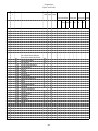


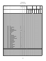

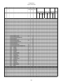


![010003E - [PROJECT.TOC] - TMG Construction Corporation](http://vs1.manualzilla.com/store/data/006000704_1-51daa2ac67e6ebfb9337b1b072f623df-150x150.png)
![1127117 - [PROJECT.TOC] - Performance Heating & Plumbing](http://vs1.manualzilla.com/store/data/005895106_1-55e9d6c83dbc31a8ba61d6bb401245cf-150x150.png)