1
SPECIFICATIONS RELOCATE AIRFIELD LIGHTING VAULT TO FACILITY 2417 FORT EUSTIS, VIRGINIA ISSUE FOR CONSTRUCTION PREPARED BY: LEIDOS Engineering 9400 North Broadway, Suite 300 Oklahoma City, Ok 73114-7401 Project Manager: James Bagby, P.E. Architectural: Kyle Lombardo, R.A. Fire Protection: Tommy Willis, P.E. Structural: David Swyden, P.E. Submitted By: LEIDOS Civil: Michael Judd, P.E. Mechanical: Jason Watkins, P.E. Electrical: Brian Crisp, P.E. Estimator: Charles Gamble, AIA, CCC Date: 12 June 2015 APPROVED BY: Specification / Design Branch Head: ___________________________ Date: __________________________ ________________________________________________________________________________________________________ Issue for Construction Specifications – Page 1 12 June 2015 This Page Intentionally Left Blank ________________________________________________________________________________________________________ Issue for Construction Specifications – Page 2 12 June 2015 SPECIFICATIONS TABLE OF CONTENTS DIVISION 0 – CONDITIONS OF THE CONTRACT (NOT APPLICABLE) DIVISION 1 - GENERAL REQUIREMENTS 01 11 00 SPECIAL CONDITIONS 01 12 00 ASSET MANAGEMENT SPECIAL CONDITIONS 01 78 00 CLOSEOUT SUBMITTALS DIVISION 2 – EXISTING CONDITIONS (NOT APPLICABLE DIVISION 3 - CONCRETE 03 30 53 MISCELLANEOUS CAST-IN-PLACE CONCRETE DIVISION 4 – MASONRY (NOT APPLICABLE) DIVISION 5 - METALS 05 50 13 MISCELLANEOUS METAL FABRICATIONS DIVISION 6 – WOOD, PLASTICS & COMPOSITES (NOT APPLICABLE) DIVISION 7 - THERMAL & MOISTURE PROTECTION 07 60 00 FLASHING AND SHEET METAL DIVISION 8 - OPENINGS 08 11 13 STEEL DOORS AND FRAMES 08 71 00 DOOR HARDWARE DIVISION 9 - FINISHES 09 90 00 PAINTS AND COATINGS DIVISION 10 - SPECIALTIES (NOT APPLICABLE) DIVISION 11 – EQUIPMENT (NOT APPLICABLE) DIVISION 12 – FURNISHINGS (NOT APPLICABLE) DIVISION 13 - SPECIAL CONSTRUCTION (NOT APPLICABLE) DIVISION 14 - CONVEYING SYSTEMS (NOT APPLICABLE) HERT13-7199 Page 1 of 2 DIVISION 21 – FIRE SUPPRESSION (NOT APPLICABLE) DIVISION 22 – PLUMBING (NOT APPLICABLE) DIVISION 23 – HEATING VENTILATION AIR CONDITIONING 23 82 02.00 10 UNITARY HEATING AND COOLING EQUIPMENT DIVISION 26 - ELECTRICAL 26 05 19.00 10 INSULATED WIRE AND CABLE 26 20 00 INTERIOR DISTRIBUTION SYSTEM 26 32 14.00 10 DIESEL-GENERATOR SET STATIONARY 15-300KW 26 36 00.00 10 AUTOMATIC TRANSFER SWITCH AND BY-PASS/ISOLATION SWITCH 26 41 00.00 20 LIGHTNING PROTECTION 26 56 20.00 AIRFIELD AND HELIPORT LIGHTING AND VISUAL NAVIGATION AIDS DIVISION 27 - COMMUNICATIONS (NOT APPLICABLE) DIVISION 28 – ELECTRONIC SAFETY & SECURITY 28 31 64.00 10 FIRE DETECTION AND ALARM SYSTEM, ADDRESSABLE DIVISION 31 - EARTHWORK 31 00 00 EARTHWORK DIVISION 32 – EXTERIOR IMPROVEMENTS 32 92 19 SEEDING DIVISION 33 - UTILITIES 33 71 02 UNDERGROUND ELECTRICAL DISTRIBUTION DIVISION 34 - TRANSPORTATION (NOT APPLICABLE) DIVISION 35 – WATERWAY & MARINE (NOT APPLICABLE) DIVISION 41 – MATERIAL PROCESSING & HANDLING EQUIPMENT (NOT APPLICABLE) DIVISION 44 – POLLUTION CONTROL EQUIPMENT (NOT APPLICABLE) ** End of TOC ** HERT13-7199 Page 2 of 2 SECTION 01 11 00 SPECIAL CONDITIONS REVISED 08 November 2013 PART 1 GENERAL 1.1 REFERENCES The publications listed below form a part of this specification to the extent referenced. The publications are referred to within the text by the basic designation only. SECTION 01 12 00 Environmental Special Conditions U.S. ARMY CORPS OF ENGINEERS (USACE) EM 385-1-1 (2003 or most current version) Safety and Health Requirements FT. EUSTIS, JBLE TELECOMMUNICATIONS BUILDING CABLING SYSTEMS STANDARDS (Ft. Eustis, JBLE Specification 27 10 10 dated 02 June 2008 or most current version) 1.2 SUBMITTALS The following items specified herein shall be submitted in accordance with SUBMITTAL PROCEDURES: SD-03 Product Data Material Safety Data Sheet (MSDS) for each item State and EPA Region 3 Notifications Recycling Report Trip Tickets Affirmative Procurement Report Exemption Form, Annex B to Ft. Eustis Affirmative Procurement Plan 32-7080 All Employee Names and Social Security Numbers Work Clearance Requests (Air Force Form 103) Quality Control (QC) Report SD-11 Closeout Submittals Survey Report Metadata Deliverables and Final As-builts Three copies of Computer-Aided Drafting and Design (CADD) digital final as-built drawings on CD’s One As-Built (Redline) Drawings Warranty of Construction HERT 13-7199 SECTION 01 11 00 Page 1 of 24 Equipment Warranty Certificate Equipment Warranty/Guarantee Record DD Form 1354 Acceptance and Transfer of Real Property Facilities Operating & Maintenance Manuals Warranty Management 1.2.1 SUBMITTAL PROCEDURES 1.2.1.1 Schedule of Material Submittals (Air Force Form 66) Information, shop drawings, certificates, test data, etc., listed on the attached AF Form 66, Schedule of Material Submittals, shall be submitted for approval to the Contracting Officer, or his/her designated representative with Form AF 3000 in accordance with the General Provisions. Whenever in this contract materials or drawings are required to be submitted by the Contractor to the Contracting Officer for approval and the material or drawings submitted are at variance with the specifications or Government drawings, but are, nevertheless, approved by the Contracting Officer, inadvertently and without consciousness of the variance, and regardless that a closer review could have revealed the variance, then such approval shall not be final unless the Contractor expressly noted in a memorandum to the Contracting Officer, on the material submittal or drawing that “this material or drawing varies from specifications in the following aspects –” or uses other works of similar clear meaning. In the event of such an inadvertent, erroneous approval, the Contracting Officer, upon discovering the variance at any stage, have the right to require the Contractor to do such rework and/or material replacement as is necessary to obtain compliance with the specifications, and the expense of such rework and material replacement shall be borne solely by the Contractor. 1.3 SCOPE OF WORK The work under this project consists of Relocation of existing Lighting Vault from Building No. 2408 to Building No. 2417 including selective building modifications in both buildings as shown on [BCE Drawing FY13-7199]. 1.3.1 Work Hours Normal duty hours for Ft. Eustis, JBLE are 0730 through 1630, Monday through Friday. Work on weekends, recognized Federal holidays, or other than normal duty hours must be coordinated with the Contracting Officer (CO) or his/her designated representative. 1.3.2 General Working Conditions a. Work shall be performed in such a manner as to cause minimum disruption to the users in the area. b. The Contractor shall notify the Contracting Officer or his/her designated representative when he intends to work so Government inspection can be provided while work is in progress. 1.4 ORDER OF WORK The Contractor shall coordinate all work with the Contracting Officer, or his/her designated representative, and the Base Civil Engineer. Before starting work at the job site, provide five days notice to the Contracting Officer or his/her designated representative and the Chief of Contract Management at 764-3268. 1.5 PHASING OF WORK – NOT APPLICABLE HERT 13-7199 SECTION 01 11 00 Page 2 of 24 1.6 APPLICABLE CODES AND REGULATIONS The latest edition of the following Building Codes shall be used for all construction under this contract: A. Air Force Engineering Technical Letter ETL 01-1, Reliability and Maintainability (R&M) Design Checklist B. American National Standards Institute (ANSI) C. American Standards for Testing Materials (ASTM) D. Americans with Disabilities Act (ADA) E. ANSI C-2, National Electrical Safety Code (QIESC) F. Applicable Unified Facilities Guide Specifications G. Institute of Electrical and Electronics Engineers (IEEE) H. International Building Code I. International Code Council (ICC) International Plumbing Code J. International Fire Code K. International Mechanical Code L. International Society of Automation (ISA) M. Ft. Eustis, JBLE Electrical, Fire, and Communications Design Standards – latest edition N. Leadership in Energy and Environmental Design (LEED®) for New Construction and Major Renovation v2.2 Reference Guide O. Life Safety Code, NFPA 101 P. MIL Handbook 1190 Q. National Electrical Code (NEC) R. National Electrical Manufacturers Association (NEMA) S. National Fire Protection Association (NFPA) T. National Fire Protection Association Codes (NFPA) – latest edition U. Supervisory Control and Data Acquisition (SCADA) V. Underwriters Laboratories, Inc. (UL) W. Unified Facilities Criteria (UFC) 3-600-01, Fire Protection Engineering for Facilities X. Unified Facilities Criteria (UFC) 4-020-01, DoD Security Engineering – Facilities Planning Manual NOTE: If there is a conflict between these codes or regulations and these contract specifications, the most stringent requirements shall apply at all times. 1.7 SALVAGE Title to all materials and equipment to be demolished shall be vested to the Contractor upon removal from the base daily. The Government will not be responsible for the condition, loss or damage to such property after notice to proceed. All unsalvageable material will be disposed of legally off base. 1.8 CONSTRUCTION STANDARDS 1.8.1 General The Contractor is reminded that the construction site must be operated and maintained according to these specifications and is subject to inspection and enforcement according to all federal, state and local codes/regulations. HERT 13-7199 SECTION 01 11 00 Page 3 of 24 1.8.2 Office Trailers and Storage Units 1.8.2.1 Office Trailers If a trailer is required for work and at the discretion of the Government, an office trailer may be located at the project site. The Contractor shall request Contracting Officer approval for the trailer location. The Contractor shall make the request in writing at least fourteen calendar days prior to placement of trailer at site. All office trailers shall be located in areas as directed by the Contracting Officer or his/her designated representative. Any office trailer shall be not more than 10’ x 32’ in size, provided with a skirt on all sides, in like new condition, and painted either Langley Brown (Federal Standard 595a, 20100), Langley Beige, or white. Office trailers in need of painting and / or repairs or that are in an unsightly condition will not be al-lowed at the project site. Displayed on the exterior of all trailers shall be a nameplate which has the name of the Contractor’s company, name for Contractor’s point(s) of contact (POC) and telephone number where he or she can be reached, contract number, project number, title and date trailer was placed on site where located. 1.8.2.2 Storage Units The Contractor shall request Contracting Officer approval for the siting, size and color of Storage Units, CONEX boxes and dumpsters. The Contractor shall not bring any such items to the job site without the Contracting Officer’s approval. All storage units shall be painted Langley Brown (Federal Standard 595a, 20100), Langley Beige or white. Displayed on the exterior of all storage units shall be a nameplate which has the name of the Contractor’s company, name for Contractor’s point(s) of contact (POC) and telephone number where he or she can be reached, contract number, project number, title and date unit was placed on site where located. 1.8.3 On-Site Storage Units Availability and size of material lay down area shall be restricted as noted on the contract documents or as discussed during the preconstruction conference. The Contractor shall consolidate all bulk or large quantities of materials at the construction site in area(s) approved by the CO. All such items shall be stored neatly grouped together. Bulky or unsightly construction materials, heavy or light equipment or tanks shall not be delivered to or stored on the construction site for any period longer than seven calendar days prior to use, installation in the project or start of construction. The Contractor shall store all supplies and equipment on project site to preclude theft or damage. Protection and security for materials and equipment on site is the sole responsibility of the Contractor. The Contractor shall not use any area(s) for material or equipment storage that has not been approved by the CO or his/her designated representative. 1.8.4 Fencing and Screening Contractor shall enclose the lay down area with a chain link fence that has been erected to a minimum height of six feet. Contractor’s lay down area shall also be screened from view. Screening shall be fabricated of 100% Polypropylene, woven, 92% blockage fabric that has been mechanically attached to the fence for the full height of the fence. The edges of each section of screening fabric shall be finished with a reinforced hem. Attachment points shall be reinforced fabric built into the hem or metal grommets built into the hem. All fabric used for screening of the construction lay down area shall be UV rated and dark brown or dark bronze in color. Fence screening fabric shall be inspected weekly to insure all sections remain properly in-stalled and taut at all times. 1.8.5 Locksets If locksets are installed as a result of this project, the Contractor shall provide cylinders and cores for new locks. Cylinders and cores that the Contractor provides shall have seven-pin tumblers using the A2 system and WB keyway – except for dormitories, which use the A4 system and WC keyway. All cylinders will be from a single manufacturer. All cores will be stamped with a key control symbol in a concealed place on the core. (For information only – the Best Premium WB Keyway, 7-pin core is part number 1CP7WB2.) The cylinders will be fully compatible with products of the Best Lock Corporation, which have interchangeable cores that are removable by HERT 13-7199 SECTION 01 11 00 Page 4 of 24 special control keys. The contractor shall provide keys and cores unpinned. Ft. Eustis’ locksmith will key the core for the bldg. 1.8.6 Communications The Contractor shall design and install new communications in accordance with the most current version of 733d COMM PREMISE WIRE DISTRIBUTION SYSTEM SPECIFICATIONS (Ft. Eustis, JBLE) 1.8.7 Electrical Panels Any electrical panel altered by the Contractor shall have every circuit and circuit modification legibly identified as to its clear, evident and specific purpose and use. The identification shall include sufficient detail to allow each circuit to be distinguished from all others. Spare positions that contain unused overcurrent devices or switches shall be described accordingly. The identification shall be included in a circuit directory that shall be located on the face or inside of the panel door in the case of a panelboard and located at each switch in a switchboard. No circuit shall be described in a manner that depends on transient conditions of occupancy. This is in accordance with §408.4 of the 2008 version of the National Electric Code (NEC). 1.9 CONTRACTOR OPERATIONS 1.9.1 Grassy Areas Grass and weed growth in excavated materials that are stockpiled on site shall be controlled or cut weekly. Weeds and grass within the construction site shall also be controlled or cut weekly and any bushes or shrubs shall be trimmed monthly. Areas disturbed by construction or those areas required by the plans to be “re-seeded” shall be re-established by hydroseeding only. Straw shall not be used as a cover for freshly seeded areas. 1.9.2 Privately Owned Vehicles (POVs) POVs used by Contractor personnel to commute to work are required to park in existing parking lots. Contractor or Contractor’s employees, including subcontractors, shall not park any personally owned vehicle (POV) or company or delivery vehicle on grassy areas near or in the construction site without prior approval from the Contracting Officer, or his/her designated representative. When allowed, parking on grassy areas will only be for shortterm delivery purposes (to include heavy tools, equipment, construction materials, etc.). Use designated hard surfaces or existing parking lots near or within the project site for parking of POVs or company or delivery vehicles. Tire and track impressions (ruts) created on wet or soft soil by vehicles or equipment used in the Contractor’s operations shall not be left for more than one day after removal of such vehicle or equipment that cased the rutting. The Contractor shall restore the affected area(s) of the site to its original condition within that one-day period. 1.9.3 Site Cleanup During construction, the Contractor shall maintain all areas in a neat and orderly manner. Contractor shall keep the construction site cleaned daily of all construction trash, trash generated by employees, debris or demolished building materials. If the work areas are not kept neat and orderly, the Contractor must return to the area to correct the unacceptable condition. During the laying of asphalt roads, streets or parking surfaces, areas soiled by residual asphalt shall be cleaned daily. The Contractor shall treat with lime entrances and exits to asphalt work site at his/her own expense. 1.9.4 Access Routes Access routes to this project shall be limited through the Base as shown on the plans. The Contractor shall use the Base Entry Access Point at Building 2 on Washington Boulevard for haul route entry and exit. HERT 13-7199 SECTION 01 11 00 Page 5 of 24 1.9.5 Removal of Formwork The Contractor shall remove all concrete formwork and boards within fourteen calendar days after concrete pour. 1.9.6 Noise Control The Contractor shall comply with all applicable state, local and installation laws, ordinances and regulations relative to noise control, to include applicable quiet hours exclusive to Ft. Eustis, JBLE. . There shall be absolutely no construction activities in or around the construction site prior to or after the hours designated in “Work Hours” paragraph above without an approval from the Contracting Officer, or his/her designated representative. This restriction also applies to holidays also. 1.9.7 Excavations All trenches/excavations shall be back filled and compacted to 95% of maximum Proctor density. Trenches will be top dressed with no less than three inches of shifted topsoil and then compacted. The finished area will be free of all debris, rocks and then graded to conform to the surrounding area. The area will be hydroseeded in accordance with SECTION 32 92 19 HYDROSEEDING of the specifications. 1.9.8 In-Ground Obstructions Any type of raised obstructions shall have the surrounding soil backfilled, compacted to 95% of maximum Proctor density, and graded. The area will be top dressed as above to within three inches of the top of obstruction. Ground level obstructions will have the area dressed to the level of the obstruction. The area will be hydroseeded in accordance with SECTION 32 92 19 HYDROSEEDING of the specifications. 1.9.9 Architectural Compatibility – NOT APPLICABLE 1.9.10 Patching All holes in walls or other parts of the structure where material or equipment is removed or replaced shall be sealed, painted, caulked or plugged neatly with original type of materials to match the existing part of the structure so involved. All above work and materials shall be approved by the Contracting Officer or his/her designated representative. 1.9.11 Repairs Replace or restore all pavement, curb and gutter, and sidewalk disturbed by operations under this contract to the original condition, except where shown or specified otherwise. Compact backfill in pavement repairs with mechanical tampers to affect a density equal to adjacent subgrade. Replace pavement with equal materials and equal thicknesses to that removed, unless indicated otherwise. Each pavement area shall be replaced immediately after the work operation for that area is completed. At the Contractor’s option, a temporary repair with a surface of bituminous concrete may be made immediately and removed and the permanent repair made before completion of the contract. 1.9.12 Marking Contractor shall not mark any curb or pavement with paint. 1.9.13 Protection Requirements The Contractor shall at all times protect and preserve the property of the Government which is within the work area and could be affected by the accomplishment of the work specified and indicated, and all parties and individuals within or near the work areas who could be endangered by the installation of the work. HERT 13-7199 SECTION 01 11 00 Page 6 of 24 1.9.14 Accidental Spills In the event of fuel spillage during the performance of this contract, the Contractor shall be responsible for its containment, clean-up and related disposal costs. The operator shall have sufficient spill supplies readily available on the pumping vehicle or at the site to contain any spillage. In the Event of a Contractor related release, the Contractor shall immediately notify the Environmental Management Office and take appropriate actions to correct its cause and prevent future occurrences. If the federal, state, or local authorities assess any monetary fine, penalty or assessment related to the release of any substance by the Contractor, his/her employees, or agents during the performance of this contract, the Contractor shall be solely liable for its payment, authorizes the United States Air Force to withhold such form of payment and otherwise indemnify and hold the United States Air Force harmless. 1.10 ENVIRONMENTAL PROTECTION. (NOT USED) 1.11 PROTECTION OF GOVERNMENT PROPERTY 1.11.1 General The Contractor shall at all times protect and preserve the property of the Government which is within the work area and could be affected by the accomplishment of the work specified and indicated, and all parities and individuals within or near the work areas who could be endangered by the installation of the work. Protection requirements include protecting the interior of the facility from inclement weather. Any actions necessary for adequate protection are solely the Contractor’s responsibility. Any temporary boarding of windows or doors must be painted Langley Brown or Langley Beige to match the exterior. 1.11.2 Protection of Equipment Contractor is required to cover equipment that is to remain in place within the area of contract operations and protect it against damage or loss and store equipment that is removed in performance of work where directed or use in work as required by drawings and specifications. Equipment temporarily removed shall be protected and returned equal to its condition prior to starting work at no additional expense to the Government. Security for equipment or material that is to be reused and is removed for temporary storage shall be the sole responsibility of the Contractor. 1.11.3 Protection of Grounds Contractor shall provide protective barriers for all grass, trees, shrubs, sidewalks, curbs and gutters within the construction boundary. Furthermore, such items, including grass, outside the construction boundary shall also be protected during delivery of materials or moving of equipment. Damages caused by the Contractor to existing grounds, plants, pavements, utilities, work by others, fixtures, or furnishings shall be repaired by the Contractor. Such repairs shall be of as good condition as exited before the damaging, unless such existing work is scheduled for removal or replacement by the work requirements of the contract. This requirement also pertains to grading of site to remove all clods and grade irregularities prior to final inspection and acceptance. The Contractor may be required to install temporary fencing to protect the site, at no cost to the Government. 1.12 SAFETY 1.12.1 Safety Barriers and Signs Contractor shall provide barricades, traffic control signs and construction safety signs that meet industry standards. Actual location, size and final arrangement of these items shall be discussed and approved by the Contracting Officer prior to installation. Such approved items shall be of uniform size, design and color. All cones, barricades, warning lights, temporary signs and protective devices shall conform to the current requirements of the Federal Highway Administration’s Manual of Uniform Traffic Control Devices for Streets and Highways HERT 13-7199 SECTION 01 11 00 Page 7 of 24 (MUTCD) and the US Army Corps of Engineers Safety and Health Requirements Manual EM 385-1-1. http://mutcd.fhwa.dot.gov/pdfs/2003r1r2/pdf_index.htm 1.12.2 Employee Health and Safety 1.12.2.1 Compliance In order to provide safety controls for protection to the life and health of employees and other persons; for prevention of damage to property, materials, supplies, and equipment; and for avoidance of work interruptions in the performance of this contract, the Contractor shall comply with all pertinent provisions of the Corps of Engineers Manual, EM 385-1-1 (2003), entitled “Safety and Health Requirements Manual”, as amended. The Contractor will also take or cause to be taken such additional measures as the Contracting Officer or his/her designated representative may determine to be reasonably necessary for the purpose. 1.12.2.2 Subcontractor’s Compliance Compliance with the provisions of this clause by subcontractors will be the responsibility of the Contractor. 1.12.2.3 Safety Records The Contractor will maintain an accurate record of, and will report to the Contracting Officer or his/her designated representative in the manner and on the forms prescribed by the Contracting Officer or his/her designated representative, exposure data and all accidents resulting in death, traumatic injury, occupational disease, and damage to property, materials, supplies and equipment incident to work performed under this contract. 1.12.2.4 Notification of Non-Compliance and Corrective Action The Contracting Officer or his/her designated representative will notify the Contractor of any noncompliance with the foregoing provisions and the action to be taken. After receipt of such notice, the Contractor shall take immediate corrective action. Such notice, when delivered to the Contractor or his/her representative at the site of the work, shall be deemed sufficient for the purpose. If the Contractor fails or refuses to comply promptly, the Contracting Officer or his/her designated representative may issue an order stopping all or part of the work until satisfactory corrective action has been taken. No part of the time lost due to any such stop orders shall be made the subject of claim for extension of time or for excess costs or damages by the Contractor. 1.12.3 Applicable Publications The publications listed below form a part of this specification to the extent referenced. The publications are referred to in the text by basic designation only. a. Code of Federal Regulations (CFR): (1) OSHA General Industry Safety and Health Standards (29 CFR 1910); Publication V2206; OSHA Construction Industry Standards (29 CFR 1926). One source of these regulations is OSHA Publication 2207, which includes a combination of both Parts 1910 and 1926 as they relate to construction safety and health. They are for sale by the Superintendent of Documents, U.S. Government Printing Office, Washington, DC 20402. b. National Emission Standards for Hazardous Air Pollutants (40 CFR, Part 61). c. Federal Standard (Fed. Std.): (1) 313A Material Safety Data Sheets, Preparation and the Submission to the BioEnvironmental Office on Ft. Eustis, JBLE. Safety and Health Requirements Manual, EM 385-1-1 (2) Use of Asbestos Containing Material or any Class 1 ozone depleting chemical compounds is prohibited at Ft. Eustis, JBLE, DA Circular 40-83-4 (3) Work covered by this section: This section is applicable to all work covered by this contract. HERT 13-7199 SECTION 01 11 00 Page 8 of 24 (4) Definition of Hazardous Materials: Refer to hazardous and toxic materials/substances included in Subparts H and Z of 29 CFR 1910 and to others as additionally defined in Fed. Std. 313. Those most commonly encountered include asbestos, lead paint, polychlorinated biphenyl’s (PCBs), explosives and radioactive material, but may include others. The most likely products to contain asbestos are sprayed-on fireproofing, insulation, boiler lagging and pipe covering. 1.12.4 Precautions Against Hazards 1.12.4.1 Welding, Cutting and Burning All welding and cutting operations shall be done in accordance with nationally recognized good practice. The current publications of the American Welding Society, 2501 NW 7th Street, Miami FL 33125, and the National Fire Protection Association, 470 Atlantic Avenue, Boston MA 02110, shall be used as a minimum standard of nationally recognized safety procedures in welding and cutting. The Contractor shall provide the necessary methods of fire extinguishment and fire prevention, and before operations begin, clear all welding and cutting operations with the representative of the Contracting Officer or his/her designated representative. The Contractor shall request and receive a hot works permit from CEF. Contact Chief Douglas Faber, 757-878-4281 Ext 321. before preparing for such operations. The Contractor shall discontinue all burning, welding or cutting operations one hour prior to the end of the normal workday. The Contractor shall provide a workman to remain at the site for thirty minutes after discontinuing the above operations. This workman shall make a thorough inspection of the area for possible sources of latent combustion. Any unsafe conditions shall be reported to the Fire Department for their investigation – EMERGENCY PHONE NO 911. 1.12.4.2 Open Flames The use of open-flame heating devices will not be allowed except by special permission of the Contracting Officer or his/her designated representative. Such permission will not be granted unless the Contractor has taken all venting precautions. Burning trash, brush or trees on the job site will not be allowed unless specific approval is granted for each incident by the Contracting Officer or his/her designated representative. Approval for the use of open fires and open-flame heating devices will in no way relieve the Contractor from the responsibility of any damage incurred because of fires 1.12.4.3 Flammable Liquid Storage Flammable liquids shall be stored and handled in accordance with the Flammable Liquids Code (No. 30) of the National Fire Protection Association. Flammable liquids shall not be stored in the Contractors storage trailers. 1.12.4.4 Technical Services The Langley Fire Department, Technical Services Section, (757) 764-4275, is available for assistance concerning fire hazard questions. 1.13 SECURITY 1.13.1 General Base Requirements Access to Ft. Eustis, JBLE is restricted to those Contractor and subcontractor employees required for the performance of this contract and only for the performance period of this contract. Contractor passes are issued by the Pass and Registration Section, Building 2 (Visitor Control Center, at the Base Access Entry Point on Washington Blvd.), after a signed letter from the Contractor listing all employee names and social security numbers has been delivered to and approved by the Contracting Officer or his/her designated representative. Procedures for requesting Base Passes for employees and Contractor vehicles will be further explained during the preconstruction conference. HERT 13-7199 SECTION 01 11 00 Page 9 of 24 1.13.2 Emergency Security Situations If a security violation is detected from any cause, it may result in the cessation of all work and evacuation of the area by all Contractor personnel to a point to be determined by the Security Forces Supervisor at the scene. The control of construction personnel under these conditions is a Security Forces Officer and their orders shall be followed in detail. Construction will be permitted to resume as quickly as possible. The individual causing the violation may be apprehended, and if so, will be processed and released to a responsible supervisor; such person might be away from his/her work site as long as 1 to 1½ hours. If a hostile situation is detected because of the construction activity, the entire crew may be removed from the area and detained until competent authority approved their release. 1.13.3 Work In Special Security Areas 1.13.3.1 Escorts Government shall provide all escorts required for access to security areas while working on construction projects at LAFB. 1.13.3.2 Applicable Security Criteria AFI 31-101, The Air Force Installation Security Program shall apply to construction projects at Ft. Eustis, JBLE. 1.13.4 Controlled Areas 1.13.4.1 General All work to be performed on this project is within the boundary of a USAF Installation and will be confined to the immediate vicinity of buildings 2408, 2417, 2416 and the underground work in between. Full operational status of the mission and Security Forces will be maintained throughout the contract period. If deemed necessary by the Contracting Officer, to facilitate contract work while preserving strict security, a Contractor free zone will be established around each work area, and a combination of entry control, internal movement and surveillance techniques will be employed. Security procedures and USAF Security Forces actions will take precedence over all concerns at the time of emergencies or mission operations. The use of deadly force is authorized to protect government resources. 1.13.4.2 Entry Control Entry into the work areas will be by Army Form for Visitor Pass and an Entry Authority List provided by the Contractor to the Chief of Security Forces. The Base Commander retains the authority to deny entry to any person(s). Security Forces and Escort Officials execute this authority for the Base Commander. 1.13.4.3 Identification Permits The Contractor is responsible for requiring each employee to display an identification permit while within the area. All identification permits shall be immediately delivered to the Contracting Officer or his/her designated representative, for cancellation upon release of any employee or termination of contract work, whichever is sooner. All Contractor personnel shall stay within the boundaries of the guarded work zone. Subcontractors, material deliverers or other workers must be pre-identified 48 hours in advance of their arrival by an Entry Authority List approved by the Contracting Officer or his/her designated representative. This list will contain the full name, SSAN and the base pass number. If this notification is not received, some delay may be expected 1.13.4.4 Search Procedures Search procedures will be in effect at all times. Each time a Contractor personnel enters the secure area the vehicle and cargo, briefcases, toolboxes, etc. may be searched. Individuals are also subject to search by the use of a HERT 13-7199 SECTION 01 11 00 Page 10 of 24 metal detector. Primary emphasis will be placed on locating explosive devices, instruments of espionage, unauthorized individuals and other objects of a suspicious nature. The Contractor shall store tools and cargo that are not required for the job in his/her own facility that will be located in a designated area. 1.13.4.5 Internal Controls The boundaries of the designated work areas will be under surveillance of armed guards. Contractor personnel must remain within the boundaries of the designated area and shall enter or depart the work areas only through the designated Exit / Entry Point. The Contractor shall insure all persons are aware of the boundaries, and that they are to remain within the work zone. 1.13.4.6 Security Manager The Contractor shall designate a representative as Security Manager to coordinate security matters. At least 48 hours in advance of a change in work hours, the Security Manager shall notify the Contracting Officer or his/her designated representative, who will notify the Security Forces. 1.13.4.7 Housekeeping The Contractor shall keep the work area neat and tidy. Clean up shall be accomplished daily, and all piles of materials, equipment and debris that could afford cover or concealment for unauthorized persons shall be removed from the area. Storage areas will be designated and the Contractor shall not store anything within thirty feet of the boundary fence. 1.13.4.8 Power Interruptions Power interruptions necessary as a part of the construction project shall be coordinated with the Contracting Officer or his/her designated representative who will notify the Base Civil Engineer, Central Security Control and (Control Tower occupants). The request for interruptions shall include reason, date, time, area affected and duration, and shall be submitted to allow notification at least two days in advance of the interruptions. 1.13.4.9 Repair Responsibilities Any damages or alteration to any security facility, i.e., fence, lighting, communication cables, will be repaired, replaced, or suitable substitute provided by the Contractor prior to nightfall of the day such action occurred or was detected. 1.13.4.10 Overnight Storage of Construction Machinery All construction machinery that is self-propelled (tractors, backhoes, dozers, trucks, etc.) will not be allowed to remain within the Controlled Area overnight. Such vehicles must be parked in a designated area thirty feet beyond the boundary fence, locked and keys removed. 1.13.4.11 Mission Operation Occupant and Security Operations will be continuous throughout the contract period and will necessitate nominal constraints on Contractor operations. Planning between the Contracting Officer or his/her designated representative and mission units can eliminate most constraints except those caused by unforeseen events. During any movements of security re-sources into or from the Controlled Area, construction will be halted prior to the movement and the construction crew will be relocated to an area away from the convoy route or destination. Under no circumstance will the reason for this relocation be announced to the Contractor. The Site Supervisor will be responsible for insuring all Contractor personnel are positioned away from the convoy routes and destination. Contractor personnel shall obey all instructions of Security Forces that pertain to their movement and activity. However, Security Forces will not interfere or halt any affect on rate of work or quality of work; their interference will pertain only to that necessary to protect security resources, if present. HERT 13-7199 SECTION 01 11 00 Page 11 of 24 1.13.4.12 Delays In Entering And Leaving Work Area The Contractor may experience delays due to compliance with entrance/exit requirements of controlled areas. The Contractor shall not be compensated for reasonable delays in accessing the site. Also, due to the nature of controlled areas, the Contractor may be requested to leave the controlled area at any given time. The Contracting Officer may extend the contract performance time when area designations change while the Contractor is working. 1.13.4.13 Safety Flame and spark producing equipment (i.e., matches, lighters, vehicle cigarette lighters) shall be surrendered at the Entry Control Point prior to entry to the area. Smoking within the area is prohibited except in Contractor provided approved smoking areas. The use of flame and spark producing equipment within the area is discouraged; however, in the event that it is necessary to use electric welders, oxygen-acetylene torches or other spark producing devices, the Contractor shall notify the Contracting Officer or his/her designated representative. Should a hazardous condition arise during the use of such devices, contact the Fire Department (Main Base: 911). All Contractor personnel are subject to base safety and traffic regulations and may be barred from motor vehicle operation for cause. 1.13.5 Airfield Requirements 1.13.5.1 Contact Base Operations Contractor shall contact Ft. Eustis Base Operations (757-878-3398), for construction restrictions involving the flightline, taxiway and runway areas and shall comply with Air Force Instruction AFI 13-213. 1.13.5.2 Radio Communication with Tower Two-way radio contact on VHF Radio capable of communication with the Air Traffic Control Tower on the ramp net (163.4625 MHz) is required at all times for all personnel and groups of personnel working on the flightline, taxiways and runways. Contractor shall coordinate radio issuance with the project inspector. 1.14 HISTORIC DISTRICT/ARCHITECTURAL COMPATIBILITY – NOT APPLICABLE 1.15 RECORDING AND PRESERVING HISTORICAL AND ARCHAEOLOGICAL FINDS 1.15.1 Preservation All items having any apparent historical or archeological interest, which are discovered in the course of any construction activities shall be carefully preserved. The Contractor shall leave the archeological find undisturbed and shall immediately report the find to the Contracting Officer or his/her designated representative so that the proper authorities may be notified. 1.15.2 Rehabilitation All repair, maintenance, and construction must be completed in a manner that is consistent with the Secretary of the Interior’s “Standards for Historic Preservation Projects” and the Secretary’s “Illustrated Guidelines for Rehabilitating Historic Buildings”. 1.16 EXCAVATION REQUIREMENTS The Government will furnish the Contractor with an approved AF Form 103, BCE Work Clearance Request, indicating any special precautions or areas that will be marked (for utilities). The contract drawings, AF Form 103 and marking will indicate all information the Government has knowledge of, but will not indicate all conditions that may occur in the field. The Contractor shall not begin (work) excavation until the Clearance Request is isHERT 13-7199 SECTION 01 11 00 Page 12 of 24 sued. The Contractor shall be responsible for removing all markings made for his benefit as soon as the need for an individual mark is passed. The Government will mark utilities one time only. Maintaining these marks or additional marking is the responsibility of the Contractor. 1.16.1 Acquiring a Work Clearance Request – NOT APPLICABLE 1.16.2 Miss Utility Contractor shall contact Miss Utility (1-800-552-7001) at least 48 hours prior to excavation to identify nonArmy/Air Force-owned underground utilities (cable TV, Bell Atlantic and Virginia Power, etc.). Notices to Miss Utility are good for 15 working days; after that period, Contractor shall renew the notice. Miss Utility is open 24 hours, seven days a week. Calls after 1700, before 0700, on weekends and on holidays are accepted for emergencies only. Holidays include New Year’s Day, Martin Luther King Day, President’s Day, Memorial Day, Independence Day, Labor Day, Veteran’s Day, Thanksgiving Day, Day after Thanksgiving and Christmas Day. After 48 hours, Contractor should contact Miss Utility to confirm that clearance/marking operations have been completed. The Contractor must wait an additional 24 hours if any operators or contract locators have not responded to the Ticket Information Exchange (TIE) system request within the first 48 hours. 1.16.3 Markings 1.16.3.1 General Requirements for Marking Utilities a. Prior to commencing any excavation, the Contractor must inspect the site for clear evidence of unmarked facilities. If evidence of such facilities is present, the excavator must notify the notification center and wait an additional three hours for the facilities to be marked. Army/Air Force-owned utilities will be marked by the fort shops via work order on a reimbursable basis. Contractor is responsible for all costs associated with marking utilities. b. The Contractor may choose to wait 72 hours and begin work after that time if there is no evidence that any underground facilities remain unmarked. However, it is recommended that Contractors contact the TIE system and confirm the status of underground facilities before they commence work. c. After the markings have been made, Contractors are required to maintain a minimum clearance of two feet between a marked, underground utility line and the cutting edge of any power-operated excavating equipment. If excavation is required within two feet of any marking, it shall be performed very carefully with hand tools in accordance with Virginia Code Section 56-265.24. d. If, during the course of excavation, a utility line has been exposed, before backfilling, the Contractor must inspect these facilities to ascertain if the facilities have been damaged. If damage of any kind is discovered or suspected, it is the Contractor’s responsibility to immediately notify the utility owner directly. The Contractor must NOT attempt to repair damaged facilities. e. Maintain any paint marks or stakes indicating underground utilities/lines as required during the duration of work or thirty calendar days from date of approved AF Form 103 (whichever is earlier). Note that Miss Utility clearance expires after fifteen working days. 1.17 OCCUPANCY AND SERVICES TO EXISTING FACILITIES a. The buildings will be occupied during the course of the contract. The Contractor shall sequence and arrange his work to minimize disruptions of the building’s services. Time and duration for interruption of utility services shall be approved by the Contracting Officer, or his/her designated representative. Work within or affecting the interior of the existing building shall be consolidated for each work area and the Center Manager notified, through the Contracting Officer or his/her designated representative, a minimum of 24 hours in advance of construction work (so that children / equipment / furniture / operations can be moved and/or secured) HERT 13-7199 SECTION 01 11 00 Page 13 of 24 1.18 UTILITIES All reasonable amounts of water and electricity required for this work will be made available to the Contractor if such utilities exist at the project site. Temporary lines, connections, installation, maintenance and removal shall be the Contractor’s responsibility. The Contracting Officer, or the Contracting Officer’s designated representative, shall approve any temporary lines and connections. All services are subject to discontinuance without notice to the Contractor in an emergency. Three-phase power may not be available. The Contractor shall provide his/her own necessary utilities when such utilities are not available at the project site. 1.19 UTILITY OUTAGES AND TRAFFIC Contractor shall request utility / power outages or changes to normal traffic flow pattern at least 14 calendar days in advance of disruption or change to either. For medical facilities, a notice of at least 30 calendar days is required. The contractor is responsible for supplying temporary restroom facilities if a planned water outage occurs during normal duty hours or affects operations of critical and/or 24-hour manned facilities. 1.20 CONVENIENCE FACILITIES Existing restroom facilities may not be used by construction personnel. The Contractor shall maintain, in a neat and sanitary condition, such accommodations for the use of his employees. 1.21 SUPERVISION 1.21.1 Superintendent The Contractor shall employ a construction superintendent to oversee all work under this contract. The superintendent shall remain at the project site at all times when work is in progress except for such incidental errands required by his/her duties. The superintendent is responsible for the proper coordination and timeliness of the work, and for proper workmanship of all trades; therefore, his/her absence from the project site without a suitable substitute representative of the Contractor shall be considered as damaging to the Government. The ability of the superintendent, based on his/her knowledge and experience, are essential to the proper execution of the work, as is his/her ability to communicate and direct the efforts of those performing the work. 1.22 GOVERNMENT FURNISHED PROPERTY (NOT USED) 1.23 RECORD DRAWINGS 1.23.1 Record of Work Progress During the progress of the work, the Contractor shall keep a careful record at the job site of all changes, corrections and deviations from the layouts and details shown on the drawings to include all contract modifications. The Contractor shall enter such changes on project drawings promptly, but not later than on a weekly basis. Such revised drawings shall be considered “redline” as-built drawings. 1.23.2 Record of Underground Utilities Where underground utilities are installed, note the elevation of the utility installed every fifty feet. Where new utilities cross existing utilities, note the elevation of the new and existing utility and the vertical or horizontal separation. Where new utilities run parallel to new and existing utilities, note the elevation at which installed and the horizontal and vertical separation between utilities. HERT 13-7199 SECTION 01 11 00 Page 14 of 24 1.24 DELIVERABLES AND FINAL AS-BUILTS 1.24.1. Contract Services The contractor shall coordinate with Geobase office prior to project/design effort and once again prior to submitting the finished product. The contractor shall provide deliverables in the following format: External-to-building data should be delivered in GIS. Internal-to-building data should be delivered in CAD. All locational base map (point, line and polygon feature(s)) data collected shall be delivered in ESRI ArcGIS 10.x or later digital format along with the original source files. The geospatial files shall have an external spatial reference (.prj) file attached specifying the parameters of the coordinate system used (as provided by the government). All topologically correct geospatial data shall overlay on the installations latest orthorectified imagery provided by the government, using the same coordinate and projection system of the imagery (WGS_1984_UTM_Zone_18N_Projection: Transverse_Mercator, Units: Meters). All accuracy errors shall be reported to the contract program manager and to the GeoBase office. All graphic and non-graphic data will be collected in the format defined by the Spatial Data Standards Facilities, Infrastructure and Environmental (SDSFIE) AF Adaption release 3.0 (or the most current version available), except where modified by the Government. The contractor shall provide a quality control (QC) report that must state whether all inconsistencies in the data generated were corrected, or it must detail the remaining errors by case. The contractor shall utilize a topology build and clean routine to assure that there are no overshoots or undershoots in the line work, slivers or dangles in polygons, and that there is complete closure of polygons with a maximum fuzzy tolerance value of 10-9. The quality report must identify the software (name and version) and satisfy these conditions: a. The edges of all digitized vector data or raster imagery must exactly match digitally with those of all adjacent maps. b. The digital representation of the common boundaries for all graphic features must be the same, regardless of feature layer. Each feature within a layer must be represented by a single graphic element (e.g., polygon, line or line string). c. Lines and line strings which represent the same graphic element must be continuous (i.e., not broken or segmented), unless that segmentation reflects a specific visual line type. Lines or line strings representing the same type of data must not cross except at intersections. d. Polygons must be closed (i.e., the first x- and y-coordinates must exactly match the last x- and ycoordinates). Each polygon must have a single unique centroid to which attributes (i.e., an attribute table) can be attached. Polygons of the same coverage must not overlap and must cover the area of interest completely (i.e., have no gaps in coverage). e. All graphic elements that connect must exactly connect digitally, without overlaps or gaps. f. Straight lines must be represented by only the beginning and ending x- and y-coordinate points. Line strings must not cross back on themselves or be of zero length. Feature Attributes: The contractor shall identify the classification, type, size, location, ID number and any other necessary attributes (specified by the Government) for all surveyed, mapped, designed or proposed features. a unique number for each feature record (SDSFIE primary key) HERT 13-7199 SECTION 01 11 00 Page 15 of 24 installationID (4 letter ACES-RP installation code) realPropertyUniqueIdentifier (where applicable - links to Facility_NBR in ACES-RP) buildingNumber (where applicable) a common name or description of the feature (sdsFeatureDescription, sdsFeatureName, etc.) All symbol libraries, font libraries, text size, text format, and text placement shall be prepared in accordance with and conform to the Spatial Data Standards (SDS). The contractor shall not develop new libraries without prior written approval from the Government. The contractor shall provide metadata files for all locational data produced under this contract. The metadata file shall conform to the Federal Geographic Data Committee’s “Content Standard for Digital Geospatial Metadata, Version 2.0” (or latest version) found at http://www.fgdc.gov/metadata/contstan.html. The output from the ESRI ArcCatalog metadata generator software (or compatible software) shall be the standard format for all metadata files created under this contract. In addition, the metadata data shall be provided in ASCII text format. The digital metadata files shall be provided to the Government along with each final product deliverable, unless otherwise approved in writing by the Government. Note: If delivering in GIS increases the cost over a certain dollar amount, it is acceptable to deliver georeferenced CADD format (DWG, DGN, or DXF), AutoCAD 2013 or higher. Prior written approval must be issued by the Government before this is acceptable. 1.24.2. Survey Data: The contractor shall use conventional surveying and other methods, such as a total station or Global Positioning Systems (GPS) for field data collection at an accuracy level in accordance with “Geospatial Positioning Accuracy Standards, Part 3: National Standard for Spatial Data Accuracy,” published by the Federal Geographic Data Committee (FGDC), dated July 1998. This standards document can be found at http://www.fgdc.gov/standards/status/sub1_3.html. All Survey data collected shall be provided to the Government in a digital format with an attached Survey Report identifying survey method, equipment list, calibration documentation, survey layout, description of control points, control diagrams and field survey data. A Survey Control Database (consisting of a survey marker database and a survey traverse database) will be produced for all survey control points established under this contract, and delivered in a .dbf or ASCII comma-delimited format. If GPS is used, the contractor shall use survey grade GPS, at an accuracy level of ± 2cm, when appropriate, to collect data to be overlaid onto the installation’s orthophotograph and/or base map. 1.24.3. Delivery Format Note: No deviations from the Government's established standards will be permitted unless prior written approval of such deviation has been issued by the Government. All linkages of non-graphical data with graphic elements, relationships between data objects and attributes, and report formats shall be maintained. These deliverables include, but are not limited to: Site plans As-built drawings Engineering designs, plans or surveys Topographic surveys or studies Boundary or Cadastral surveys HERT 13-7199 SECTION 01 11 00 Page 16 of 24 Master Plan drawings Utility (water, sewer, power, storm, etc.) designs, plans, surveys and studies Pavement, Grading, or Excavation plans Soil/Geology studies or surveys Environmental assessments, surveys, studies or plans Historical or Archaeological surveys, studies or plans All data deliverables shall be in a digital (electronic information) format and shall be delivered in a format that conforms to the Spatial Data Standards Facilities, Infrastructure, and Environmental (SDSFIE) release 3.0 (or latest version available) at https://app.eis.af.mil/a7cportal/ProgramGroups/Resources/GeoBase%20Documents/AF_Adaptation_30_Data_Di ctionary_v1.1/AF_Adaptation_30_Data_Dictionary_v1.1.html and A/E/C CAD Standards version 3.0 (or latest version available) at https://cadbim.usace.army.mil/CAD.. The following procedures must be performed before a file is placed on the delivery media: 1. Include all files, both graphic and non-graphic, required for the project. Make sure all files are in the same directory, and that references to those files do not include device or directory specifications. 2. Ensure all reference (external reference) files are bound and attached and without device or directory specifications. 3. Remove all extraneous graphics/text outside the project border area, and set the active parameters to a standard setting (or the setting contained in the seed or prototype file). 4. Include any standards sheets (abbreviations, symbols libraries, font libraries, color tables, pen tables, plot configuration files, user command files, etc.) necessary for a complete project. 5. Compress and/or reduce all files using the appropriate utilities. A digital media copy of the decompression utility should be provided with the delivered data, if necessary. 1.24.4. Delivery Media: CD-ROM Digital Media must have an external label listing format and version of the operating system on which the media was created (e.g. Windows7), utility (command) used for writing the files to the media, a short description of contents, a sequence number if there are multiple volumes, and the date of CD creation. A transmittal sheet must accompany the media containing the information included on the external labels, total number of volumes being delivered and a list of file names and file descriptions on each volume. The transmittal sheet must also include instructions for reading, restoring, or transferring the files from the media, and certification that all delivery media is free of known computer viruses - including the name(s) of the virus scanning software and the date the virus scan was performed. 1.24.5. Government Furnished Materials The Government will provide the contractor with data and information concerning all necessary and pertinent functions and principal features of the identified project. These items will include: The installation's latest georeferenced digital planimetric data and/or base map in ESRI Arc/Info 10.x format, or best format available, with associated data files. The installation’s latest orthorectified imagery and specified geospatial parameters (coordinate system, datum, projection, distance units). Any pertinent and necessary prototype or seed files. Frequency settings for the Real-Time Kinematic (RTK) GPS Base Station and the preferred GPS receiver specifications. Any other data or schematics deemed necessary for project completion, pending approval from the Government. HERT 13-7199 SECTION 01 11 00 Page 17 of 24 1.24.6 Government Review The Government shall review the submitted data and documentation upon completion of all stated work. Missing or incomplete items will be documented and forwarded to the Contractor for completion. Upon receipt of a complete submittal, the Government will conduct a quality review and notify the contractor within fourteen calendar days of acceptance (along with any stipulations this includes) or rejection of the deliverables described herein. Failure to adhere to any of the stated delivery specifications could result in rejection of deliverables and nonpayment. At a minimum, Contractors should submit data and documentation samples at 25% and 75% project completion to avoid the rejection of final deliverables. 1.24.7 Geo Integration Office Point of Contact Any questions regarding data collection efforts, deliverable formats or deliverable specifications should be addressed to the Geo Integration Office, contact information: 37 Sweeney Boulevard, Room 224 Ft. Eustis, JBLE, Virginia 23604 (757) 764-1164 1.24.8 As-Built Drawing Submittal At the time of beneficial occupancy, the Contractor shall submit as-built data to the Contracting Officer, or his/her designated representative, incorporating the aforementioned information into the project drawings. The Contractor shall also ensure that a separate copy of all similar as-built data is provided for delivery to the Base GeoBase Office. The as-built deliverable (plans, shop drawings, surveys, studies, imagery, designs, manuals, spare parts lists, etc.) shall be in a digital (electronic information) format and shall be delivered on standard compact disks (minimum 650 megabytes) in a format that is directly compatible with the CADD/GIS Technology Center’s Spatial Data Standards, Version 2.6 (or latest version available). No “redline” or marked-up drawings will be accepted as the final as-built drawings. The data provided shall be compatible with AutoCAD or ESRI 9.X and shall be submitted by the Contractor to the Contracting Officer, to the Base GeoBase Office, and to the Engineering Support on three separate compact discs (CDs). In addition, one set of as-built drawings will be submitted to Engineering Support on Mylar (minimum 4mil thick) media; as-builts on paper media will not be accepted. 1.25 WARRANTY OF CONSTRUCTION a. In addition to any other warranties in this contract, the Contractor warrants that work performed under this contract conforms to the contract requirements and is free of any defect in equipment, material or design furnished, or workmanship performed by the Contractor or any subcontractor or supplier at any tier. This warranty shall not limit the Government’s rights under the Inspection and Acceptance clause of this contract with respect to latent defects, gross mistakes or fraud. b. This warranty shall continue for a period of one year from the date of final acceptance of the work. If the Government takes possession of any part of the work before final acceptance, this warranty shall continue for a period of one year from the date the Government takes possession. In the event the Contractor’s warranty of this clause has expired, the Government may sue, at its expense, to enforce a subcontractor’s, manufacturer’s or supplier’s warranty. c. The Contractor shall remedy, at the Contractor’s expense, any failure to conform or any defect. In addition, the Contractor shall remedy, at the Contractor’s expense, any damage to Government-owned or controlled real or personal property when that damage is the result of: 1. The Contractor’s failure to conform to contract requirements, or 2. Any defect of equipment, material, workmanship or design furnished. d. The Contractor shall restore any work damaged in fulfilling the terms and conditions of this clause. The Contractor’s warranty with respect to work repaired or replaced will run for one year from the date of repair or replacement. HERT 13-7199 SECTION 01 11 00 Page 18 of 24 e. The Contracting Officer shall notify the Contractor, in writing, within a reasonable time after the discovery of any failure, defect or damage. f. If the Contractor fails to remedy any failure, defect or damage within a reasonable time after receipt of notice, the Government shall have the right to replace, repair or otherwise remedy the failure, defect or damage at the Contractor’s expense. g. With respect to all warranties, express or implied, from subcontractors, manufacturers, or suppliers for work performed and materials furnished under this contract, the Contractor shall: 1. Obtain all warranties that would be given in normal commercial practice, and 2. Require all warranties to be executed, in writing, for the benefit of the Government if directed by the Contracting Officer, and 3. Enforce all warranties for the benefit of the Government if directed by the Contracting Officer. h. Unless a defect is caused by the negligence of the Contractor, subcontractor or suppliers at any tier, the Contractor shall not be liable for the repair of any defects of material or design furnished by the Government or for the repair of any damage that result from any defect in Government-furnished material or design. i. Defects in design or manufacture of equipment specified by the Government on a “brand name and model” basis shall not be included in this warranty. In this event, the Contractor shall require any subcontractors, manufacturers or suppliers thereof to execute their warranties, in writing, directly to the Government. j. The warranty enumerated herein does not preclude any manufacturer warranties in excess of one year as noted in the individual specifications sections. The Contractor should read each section carefully to ensure that he/she is aware of all warranties called for in this project. 1.26 WARRANTY/GUARANTEE RECORDS 1.26.1 Certification of Equipment The Contractor shall prepare Optional Form(s) (OF) 274, Equipment Warranty Certificate, and affix the certificate(s) to all warranted components of the equipment installed during the project. When a complete mechanical system has been installed, affix the OF(s) 274 to the Mechanical Room door also. If the warranted items are in a new facility, Optional Form(s) 274 shall be placed as mentioned above. The Construction Inspector will distribute the OF 274 to the Contractor during the Preconstruction Conference. The Contractor shall place all OF(s) 274 on the appropriate equipment prior to final acceptance of the project by the Government. 1.26.2 Listing of Equipment The Contractor is required, prior to the Final Inspection to provide a listing of all equipment or material carrying a manufacturer’s warranty or as indicated in the specifications. Use the following Equipment Warranty / Guarantee Record for each item and attach manufacturer’s certificate as appropriate. Also prior to the Final Inspection, the Contractor shall provide to the Contracting Officer, or his/her designated representative, three separate bound documents which contain a copy of any and all warranties or Equipment Warranty Certificates which he/she is subject to provide under the requirements of the project specifications. HERT 13-7199 SECTION 01 11 00 Page 19 of 24 Equipment Warranty / Guarantee Record Facility No: ____________________ Project No: MUHJ _______________________ Project Title: __________________ Work Order: ______ Shop Code: __________ Item: ____________________ Location: _________ Contractor: _______________ Prefix:_________ Suffix:___________ Serial No:__________ Model No:________ Style:______ HZ:______ Volts:______ HP:______ Size:______ Frame:__________ Purchase Cost:________ Replacement Cost:______ Manufacturer:______________ Date Purchased:____________________ Date Installed:_______________________ Effective Date:____________________ Expiration Date:______________________ Replacement, New or Other:_________ Purchase Number:______________________ GSA Contract Number:______________________________________________________ Contract Inspector:_____________________________ Phone:___________________ Remarks:__________________________________________________________________ Evaluator:______________ Grade:________ Title:________ Orgn:______________ 1.27 SEASONAL HVAC REQUIREMENTS Air conditioning systems are required to be operational from 15 May through 15 September and the heating systems are required to be operational from 15 October through 01 May. Provide temporary heating or cooling during these periods if the air conditioning system or heating system is shut down to perform any work. Submit shop drawings for approval of proposed method for providing temporary heating or cooling. 1.28 TIME EXTENSIONS FOR UNUSUALLY SEVERE WEATHER This provision specifies the procedure for the determination of time extensions for unusually severe weather. The listing below defines the adverse weather days that are anticipated monthly. The listing is based upon data from the National Oceanographic & Atmospheric Administration (NOAA) or similar data. MONTHLY ANTICIPATED ADVERSE WEATHER CALENDAR DAYS JAN 13 FEB 12 MAR 12 APR 9 MAY 10 JUN 9 JUL 10 AUG 10 SEP 7 HERT 13-7199 SECTION 01 11 00 Page 20 of 24 OCT 8 NOV 10 DEC 12 1.28.1 Base Line The above schedule of anticipated adverse weather will constitute the base line for monthly (or portion thereof) weather time evaluations. Upon acknowledgment of the Notice To Proceed and continuing throughout the contract on a monthly basis, actual adverse weather days will be recorded on a calendar day basis (include weekends and holidays) and compared to the monthly anticipated adverse weather in the schedule above. The term “actual adverse weather days” shall include days impacted by actual adverse weather days. 1.28.2 Calculation of Adverse Days The number of actual adverse weather days shall be calculated chronologically from the first to the last day in each month. Once the number of actual adverse weather days anticipated in the schedule above have occurred, the Contracting Officer, or his/her designated representative, upon the Contractor’s written request, will examine any subsequently occurring adverse weather days to determine whether the Contractor is entitled to a time extension. Before adverse weather entitlement is granted, the Contractor must demonstrate that fifty percent or more of his/her workdays were affected by the subsequent adverse weather. The adverse weather must also delay work critical to the timely completion of the project. The Contracting Officer or his/her designated representative, will convert any delays meeting the above requirements to calendar days and issue a modification. Note: For all weather dependent activities, the Contractor’s schedule must reflect the anticipated adverse weather delays that are noted above. 1.28.3 Examples of Adverse Weather The following is considered as adverse weather: weather of a nature that workers cannot perform work as scheduled or get to work site (i.e. hurricane, tornado, high winds, floods, extremely cold weather, ice storm, sleet, heavy snowstorm, et cetera). 1.29 FINAL INSPECTION AND ACCEPTANCE STANDARDS 1.29.1 Seeding Within seven workdays of actual completion of work at contract site, the Contractor shall grade, rake, and seed (or sod), or prepare for seeding (or sodding). New turf and turf restoration shall be established or accomplished by hydroseeding or sodding in accordance with Section 32 92 19 HYDROSEEDING. When areas of the site are raked prior to seeding (or sodding) or for leveling of topsoil to rid the site of mounds, clods and / or ruts, the Contractor shall ensure that no clods larger than one inch are left on the site. Contractor shall restore the site to a condition and appearance similar or equal to existing before the damages occurred. Such restoration work will not be considered complete until approved by the CO or his/her designated representative. The Government will not accept sites that have not been raked and restored to this standard. Straw shall not be used as a cover for newly sown seeds or freshly seeded areas. 1.29.2 Removal of Signs and Barriers All Contractors’ stakes, traffic/safety cones and barriers, warning tape, erosion control fences, et cetera, that are erected during construction, shall be removed entirely prior to Government final acceptance of project. 1.29.3 Removal of Trailers and Storage Units All trailers, equipment/storage units, residual construction materials shall be removed from construction site within five workdays after completion of work at that job site. 1.30 DD FORM 1354 A DD Form 1354 is required whenever there is: - Initial construction of a new facility HERT 13-7199 SECTION 01 11 00 Page 21 of 24 - Addition to an existing facility Demolition of an existing facility (and all its associated related real property) Removal of, or upgrade to, an installed system In general, if the project was funded in part or in whole with minor construction (EEIC 529) or MCP funds, a DD Form 1354 is required in order to transfer the completed construction to real property records. At least forty-five days prior to the final inspection, the Contractor is required to submit a draft copy of the DD Form 1354 (available at http://www.dtic.mil/whs/directives/infomgt/forms/eforms/dd1354.pdf) for review by the 733 CED Real Property Officer (RPO). If the project has multiple facilities with multiple turnover dates or is a multi-phase construction project, interim DD 1354s shall be submitted. Upon review and validation by the RPO and incorporation of any comments, a final corrected copy shall be provided. The Contractor shall complete only those areas of the form that are applicable to the work included in this project. Both UFC 1-300-08 (available at http://www.wbdg.org/ccb/DOD/UFC/ufc_1_300_08.pdf) and the following inventory worksheet will be useful in preparing the DD-1354. A. FACILITY STRUCTURAL DATA (List overall and other category codes if multiple use facility) Facility No. Category Code Length (LF) CatCode Description Width (LF) Area (SF) Height (LF) Primary Construct Mat’l (Brick, Wood, Concrete, Siding, etc.) Total Project Cost Comments B. REAL PROPERTY INSTALLED EQUIPMENT (RPIE) SUPPORTING PRIMARY FACILITY (“X” line items) (1) Fire Protection (Suppression and Detection Systems) Facility No. Category Code 880-211 880-212 880-216 880-217 880-221 880-222 Pri. UM CatCode Description Closed Head Auto Sprinkler Open Head Deluge System Pre-Action Sprinkler System Aqueous Film Forming Foam Pre-Action Sprinkler System Auto Fire Detection System Manual Fire Alarm System, Interior Pri. UM Quantity Sec. UM Sec. UM Quantity Construction Material SF HD Not applicable SF HD Not applicable SF HD Not applicable SF HD Not applicable SF EA. Not applicable Ea Not applicable 880-223 Manual Fire Alarm System, Exterior BX Not applicable 880-231 CO2 Fire System Ea Not applicable 880-232 Foam Fire System Ea Not applicable 880-233 Other Fire System Ea Not applicable 880-234 Halon 1301 Fire System Ea Not applicable 880-235 Dry Chemical System Ea Not applicable Ea Not applicable Cost Comments (2) Security 872-841 Security Alarm System HERT 13-7199 SECTION 01 11 00 Page 22 of 24 Identify the number of systems installed (3) Energy Management and Control System (EMCS) 890-271 Energy Mgmt. & Control System (EMCS) Central Station Ea Not Applicable Attach list with model #, serial # 890-272 EMCS Field Equipment Ea Not Applicable Attach list with model #, serial # 890-273 EMCS Data Links LF Not Applicable (4) Heating, Ventilation, Air Conditioning (HVAC) NOTE ABOUT EQUIPMENT FOR A/C PLANT OR HEAT PLANT: UNIT OF MEASURE IS BASED ON CHILLER, PACKAGE UNIT, SPLIT SYSTEM OR BOILER. HOWEVER, THE COST AND EQUIPMENT INCLUDES ALL ITEMS SUCH AS AIR HANDLERS, PUMPS, MOTORS, CONDENSERS, ETC. 890-126 A/C Window Units SF TN Not Applicable 890-125 A/C Plant less than 5 TN SF TR Not Applicable 890-121 A/C Plant 5 to 25 TN TR Not Applicable 826-122 A/C Plant 25 to 100TN TR Not Applicable 826-123 A/C Plant Over 100 TN SF TR Not Applicable 890-123 A/C Central Plant SF Not Applicable 890-124 A/C From Central Plant SF Not Applicable 821-113 Heat From Central Plant SF Not Applicable 821-115 Heating Plant 750/3500 MBTU. MB Not Applicable 821-116 Heating Plant over 3500 MBTU. MB Not Applicable 124134 Operating Storage, Diesel 132-133 Pad, Equipment 811-147 Emergency Electric Power Generation Plant Attach list with model #, serial #, tonnage of EACH unit/chiller in this category. Attach list with model #, serial #, tonnage of EACH unit/chiller in this category. Attach list with model #, serial #, tonnage of EACH unit/chiller in this category. Attach list with model #, serial #, tonnage of EACH unit/chiller in this category. Use this if over 100 TN and serves 1 building. Attach list with model #, serial #, tonnage of each unit Use this if unit serves 2 or more buildings. Attach list with model #, serial #, tonnage of each unit Use this if A/C comes from central plant from cat code 890-123. Identified not as real property, but identifies cooling source Use this if A/C comes from central plant from cat code 890-123 Note: UOM is MB which stands for Millions of British Thermal Unit, so 1 MB = 1,000 MBTU. Attach list with model #, serial #, MBs of each unit Note: UOM is MB which stands for Millions of British Thermal Unit, so 1 MB = 1,000 MBTU. Attach list with model #, serial #, MBs of each unit (5) Electric Emergency Power: GA SY Not Applicable Ea KW Not Applicable (6) Equipment in General HERT 13-7199 SECTION 01 11 00 Page 23 of 24 Provide item is tank is above ground Pad is for ___________ Equipment; Length ( ), Width ( ), Depth ( ) Stand-By/Emergency Power; Attach list with model #, serial #, KW of each unit 132-133 Pad, Equipment SY Pad is for ___________ Equipment; Length ( ), Width ( ), Depth ( ) Ea C. RELATED FACILITIES SUPPORTING PRIMARY STRUCTURE (“E” line items) Facility No. Category Code Pri. UM CatCode Description Pri. UM Quantity Sec. UM Sec. UM Quantity Construction Material 135-583 Tel Duct Facility LF 135-586 Tel Pole Facility LF 132-133 Pad, Equipment 812-223 Prim Dist. Line Overhead LF Not applicable 812-224 Sec Dist. Line Overhead LF Not applicable 812-225 812-226 812-926 SY Cost Comments Ea Prim Dist. Line Underground Sec Dist. Line Underground Exterior Lighting (Street or Parking area Lights) LF LF Ea Not applicable KVA Not applicable 813-321 Transformers 824-464 Gas Mains LF 831-169 Sewage Septic Tank KG 832-266 Sanitary Sewer LF 842-245 Water Dist. Mains LF 843-315 Fire Hydrants Ea 851-143 Curbs & Gutters LF 851-145 Driveway SY 851-147 Road SY 852-262 Vehicle Parking SY 871-183 Storm Drain LF 872-247 Fence, Security LF 872-248 Fence, Interior LF 852-289 Sidewalk SY 890-187 Utility Vault (four or more transformers) SF LF D. SPECIALIZED RELATED FACILITIES SUPPORTING FACILITY (“E” line items) Facility No. Category Code CatCode Description Pri. UM Pri. UM Quantity Sec. UM 890-158 Load and Unload Platform Ea 832-255 Industrial Waste Main LF 890-144 Compressed Air Dist. LF Sec. UM Quantity Construction Material – End of Section – HERT 13-7199 SECTION 01 11 00 Page 24 of 24 Cost Comments SECTION 01 12 00 – ASSET MANAGEMENT SPECIAL CONDITIONS 1. ASSET MANAGEMENT: All work is to be performed in a manner that prevents pollution, protects the environment and conserves natural resources. CONTRACTOR ENVIRONMENTAL DELIVERABLES: The following contract deliverables are due to the Ft. Eustis project manager and Contracting representative who will in turn provide them to the Environmental Element (733 CED/CEIE). Before Contract Start (30 days) Asbestos Abatement Plan (if applicable) Lead-Based Paint Abatement Plan (if applicable) Hazardous Material Usage Request Forms Green Procurement Planning Use Forms Environmental Management System (EMS) training certifications Stormwater Permit (if applicable) Stormwater Pollution Prevention Plan (if applicable) Clean Soil Certifications Wetland Permits if applicable (Joint Permit Application (JPA) submitted to and approved by the Virginia Marine Resources Commission * (Allow 60 - 90 days for this*) During Contract Monthly Hazardous Materials Usage Report Quarterly Refuse/Recycling Reports Generator permit information Hazardous Waste/Lead/Asbestos Manifests (to be signed by Ft. Eustis Environmental Reps) End of Contract before contract close Green Procurement Exemption Form (if applicable) Green Procurement Final Usage Report All return Asbestos Manifest (signed by receiving landfill) 1.1 WASTE DISPOSAL: 1.1.1. SOLID WASTE DISPOSAL. 1.1.1.1. Compliance With Regulations All waste materials generated by any work under this contract performed on a Government installation shall be handled, transported, stored, recycled, and disposed of by the Contractor and by his/her subcontractors at any time in accordance with these specifications, all applicable Federal, state, or local laws, ordinances, regulations, court orders, or other types of rules or rulings having the same effect of law. These include but are not limited to the Resource Conservation and Recovery Act (RCRA) (40 CFR 260-270); Federal Water Pollution Control Act, as amended (33 USC Sec 1251 ET SEQ); The Clean Air Act, as HERT 13-7199 SECTION 01 12 00 Page 1 of 39 SECTION 01 12 00 – ASSET MANAGEMENT SPECIAL CONDITIONS amended (42 USC Sec 1857 ET SEQ); The Endangered Species Act, as amended (16 USC Sec 1531, ET SEQ); The Toxic Substances Control Act, as amended (15 USC Sec 2601, ET SEQ); The Solid Waste Disposal Act, as amended (42 USC 6901 ET SEQ); the Archaeological and Historic Preservation Act, as amended (16 USC Sec 469, ET SEQ), and the Virginia Solid Waste Management Regulations (9VAC20-81). The Contractor shall collect all solid wastes generated during the performance of the contract in a container/area provided by the Contractor and approved by the Contracting Officer. The Contractor shall provide appropriate containers for the collection and segregation of solid wastes, recyclables, and C&D debris generated directly and indirectly by work under this Contract. The Contractor is prohibited from using base dumpsters or other government owned/leased waste receptacles for the disposal of any solid wastes. All solid wastes shall be reclaimed, recycled, or disposed of prior to completion of work on Ft. Eustis. As proof of proper disposition of solid wastes, the Contractor shall provide legible weight receipts for solid waste disposed and materials recycled bearing the name, address, and phone number of the receiving facilities for every load of materials delivered. The weight ticket shall detail the type of material, weight of the material in pounds or tons, the date of the transaction, and a signature from a representative of the receiving facility. Receipts shall be submitted to the Contracting Officer within ten (10) calendar days after the transaction. Under no circumstances will any solid waste or hazardous materials be left at Ft. Eustis at the end of the project. Before the project is turned over to the government, the Contractor will remove all solid wastes and hazardous materials from the installation. Those items include but are not limited to dirt piles, concrete piles, asphalt piles, and rubbish piles. No materials will be left for the future use of the government UNLESS instructed to do so in writing by the government. This is to include the before mentioned items and also regular or touch-up paint, plaster, solvents, etc. If it is determined that the Contractor left materials behind, services may be terminated and/or a penalty payment to include the cost of disposal of the material by the government may be withheld from the project payment. NOTE: Hazardous materials are different from hazardous wastes so be careful not to confuse the two. Hazardous Wastes will not be removed from the installation without the 733 CED Hazardous Waste Managers signing the Hazardous Waste Manifest. The Ft. Eustis Hazardous Waste Managers can be contacted at 757-787-7366 if needed. 1.1.1.2. CONSTRUCTION/DEMOLITION DEBRIS DIVERSION: As good stewards of the environment, the government is committed to diverting its waste away from landfills to the greatest extent possible. This can be done through recycling, reusing (when directed by the government), and donating construction and demolition debris materials. The Contractor shall recycle all construction/demolition debris to the maximum extent possible. The Contractor shall make every effort to recycle materials such as but not limited to concrete (including concrete with rebar), brick, asphalt, all metals, wood, roofing materials, wallboard, ceiling tiles, etc. With prior coordination through the CO and 733 CED/CEIE, the Contractor may take scrap metals to the Ft. Eustis scrap metal yard for recycling. The following are some suggested local sites for recycling construction and demolition debris: SECTION 01 12 00 – ASSET MANAGEMENT SPECIAL CONDITIONS Local Sources of Recycling Company Address City Tidewater Fibre Old Dominion Recycling 5602 Chestnut Ave 1618 W. Pembroke Ave. Newport News S.B. Cox, Inc. 217 Cox Drive Yorktown Butler Paper 324 Newport St Suffolk Hampton Phone 2475766 7232942 9691409 5392351 Norfolk 6223970 6271095 Sims Metal 2409 Bowdens Ferry Rd 1206 E. Brambleton Ave. 2116 George Washington Memorial Hwy Tabb 5994940 Waterway Marine Terminal 1401 Precon Drive Chesapeake 3333427 Waterway Materials Corp 1401 Precon Drive Chesapeake 5450004 K.F. Wilson CrushCon Aggregates 2972 N. Armistead Ave 100 North Park Lane Dubin Metals Gutterman Iron & Metal Norfolk Hampton Hampton 8657182 7231131 Acceptable Items paper, cardboard, plastics, aluminum, glass, tin cans Aluminum, copper, steel, iron, metals, paper, tires All C & D, i.e. concrete, concrete w/rebar, wood, brick, block, steel, all metals, sheetrock, asphalt, cardboard, paper, plastics Industrial & Commercial Paper Recycling Scrap Metals, Copper, Brass, Batteries, Radiators, Aluminum Scrap Brass, Copper & Aluminum Steel, aluminum, brass, copper, stainless steel, radiators all C & D materials i.e. concrete, concrete w/rebar, lumber, asphalt Concrete, concrete w/rebar, brick, block, asphalt all C & D materials i.e. concrete, concrete w/rebar, lumber, asphalt Concrete, concrete w/rebar 1.1.1.2.1 RECYCLING AND DISPOSAL REPORTING: The Contractor shall report on a quarterly basis the tonnage of the items recycled and the amounts disposed of by landfill and amounts disposed of by regular or waste-to-energy incineration to the Project Manager, the Contracting Officer, and 733 CED Environmental Element (733 CED/CEIE) by the 5th day of each quarter (Jan, Apr, Jul, Oct) during the period of performance. This report will be for the previous quarter. The report shall list the title of the project, the project number, the Contractor’s company name and point-of-contact, phone number, the type items (i.e. concrete, concrete with rebar, asphalt, brick, scrap metals, wood, wallboard, etc) and the tonnage of those items recycled. SECTION 01 12 00 – ASSET MANAGEMENT SPECIAL CONDITIONS For all items that could not be recycled, the Contractor will provide a brief reason as to why the items could not be recycled. For items disposed of, one total tonnage can be given for items landfilled and one total tonnage for items incinerated (specify waste incinerator or waste-to-energy incinerator) instead of reporting disposal figures for the various items. For items that cannot be accurately measured, estimates will be sufficient. Use the form at Attachment 1 (Construction/Demolition Debris Recycling and Reporting) to report this information to the Contracting Officer, Project Manager, and to 733 CED/CEIE. To send it to 733 CED/CEIE, email it to [email protected] or mail it to: 733 CED/CEIE Attn: Pollution Prevention Mgr Bldg 1407 Ft. Eustis VA 23604 757-878-7378 1.1.1.3 Contain Loose Debris. Loose debris on trucks leaving the site shall be loaded in a manner that shall prevent dropping/releasing of materials on streets and conform to local ordinances/laws. Fasten a suitable cover, such as a tarpaulin, over the load before entering surrounding streets. 1.1.1.4 Trip Tickets. Contractor shall submit all trip tickets from the landfill facility, incinerators, and recycling companies to show all debris is being landfilled, incinerated, or recycled in accordance with all Federal requirements and in an approved location. These trip tickets will be submitted to the Contracting Officer who will in turn give them to the Project Manager. 1.1.2. SOIL AND PETROLEUM CONTAMINATED WASTE: 1.1.2.1. Contaminated Absorbents. All petroleum spills/releases must be cleaned up using absorbent materials. Spills caused by the Contractor will be the Contractor’s responsibility to containerize and dispose of the contaminated absorbent material. Spills caused by the government will be the responsibility of the government. Contact the base Hazardous Waste Contractor at 757-878-4123 to arrange for pick-up. 1.1.2.2. Soil. ALL soil must be tested to determine if it contains any contaminates prior to relocating it on base or disposing of it off-base. Testing and disposal of soil shall follow Virginia Solid Waste Management Regulations 9VAC20-81-660 (soil contaminated with petroleum products). Testing shall include items specified in the solid waste regulations to include but not limited to: RCRA hazardous waste characteristics (i.e., corrosivity, ignitability, reactivity, and toxicity); total metals; volatile organic compounds; semi-volatile compounds; total petroleum hydrocarbons (TPH), pesticides/herbicides; polychlorinated bi-phenyls (PCBs); presence of liquids (paint filter); Benzene, Toluene, Ethyl Benzene, and Xylene (BTEX); Toxicity Characteristic Leaching Procedure (TCLP); and total organic halides (TOX). If test results SECTION 01 12 00 – ASSET MANAGEMENT SPECIAL CONDITIONS determine “other than clean”, the material will have to be transported to an appropriate landfill or processing center based on the contaminants identified. Contaminated soils, in sludge or slurry form, shall be containerized and managed as either hazardous waste or non-regulated waste, depending on what contaminate was spilled. The containerized contaminated soil shall be the responsibility of the Contractor to dispose of such. CEIE must review the sample results and sign all hazardous/non hazardous waste manifests prior to disposal. Contact 633 CED/CEIE Hazardous Waste Program Managers for additional information. One composite sample (combined number of samples collected into a single sample) is required every 250 cubic yards of soil to be disposed. NOTE: UNDER NO CIRCUMSTANCES will soil, clean or contaminated, from Ft. Eustis be delivered to or donated to off-base sources (other than an appropriate landfill or processing center based on the contaminants identified) for use. 1.1.2.3 Soil Brought onto Base from Off-base Sources: ALL soil brought onto the installation for use will meet the terms of “Environmentally clean” soil. See guidelines established in section 1.10 of this document. 1.1.3. UNIVERSAL WASTE: 1.1.3.1. Fluorescent Lamps. The Contractor shall use environmentally-friendly green tip fluorescent lamps during lamp replacement. Upon removal of old Sylvania lamps and high intensity bulbs, the Contractor will box the lamps and manage them as universal waste. Other lamps (i.e. GE and Phillips) may be disposed directly in to regular trash. Lamps will be properly disposed of by the Contractor with waste manifest being signed by 733 CED/CEIE Hazardous Waste Program Managers. NOTE: UNDER NO CIRCUMSTANCES will bulb/ lamps be crushed on Ft. Eustis. 1.1.4. HAZARDOUS WASTE. 1.1.4.1. SITE MANAGEMENT. All material containers must be closed when not in use. Materials are to be covered as protection from weather. Each container is to be properly labeled. Do not store hazardous materials near storm drains. Upon completion of this project the Contractor shall remove all hazardous materials and hazardous waste (for associated manifest requirements see paragraph 1.1.4.3.) 1.1.4.2 Waste Characterization Samples for Floor Renovation: Waste characterization samples must be collected to determine if its meets the RCRA definition of a hazardous waste. It is the responsibility of the contractor to take and provide the sample analysis to 733 CED/CEIE. Waste debris from floor stripping or floor blasting performed on Ft. Eustis must be sampled for TCLP Metals for solid debris and must add corrosivity test for liquid stripping. Additionally, it is the contractor’s responsibility to dispose of the waste generated on this project. See manifest requirement in 1.1.4.3 SECTION 01 12 00 – ASSET MANAGEMENT SPECIAL CONDITIONS 1.1.4.3. MANIFESTS. 733 CED/CEIE will review all lab analysis or MSDS of wastes prior to signing manifests. All hazardous waste manifests must be signed by appointed 733 CED/CEIE personnel prior to removal of such waste from the base. The generator copy of the manifest must be returned to 733 CED/CEIE, 37 Sweeney Blvd, Ft. Eustis VA 23604 . 1.2 FUEL, SEWAGE, AND OTHER SPILLS: In the event of a fuel, sewage, and other toxic spillage during the performance of this contract, the Contractor shall be responsible for its containment, clean up, and related disposal costs and will notify 733 CED/CEIE immediately. The operator shall have sufficient spill response supplies readily available on the pumping vehicle and/or at the site to contain any spillage. In the event of a Contractor-related release, the Contractor shall immediately notify the Asset Management Office and the Contracting Officer and take appropriate actions to correct its cause and prevent future occurrences. If the federal, state, or local authorities assess any monetary fine, penalty, or assessment related to the release of any substance by the Contractor, his/her employees, or agents during the performance of this contract, the Contractor shall be solely liable for its payment, authorizes the United States Air Force to withhold such from payment and otherwise indemnify and hold the United States Air Force harmless. 1.3 ASBESTOS OR LEAD BASED PAINT [Contact 733 CED/CEIE to determine any known presence of these materials] 1.3.1. ASBESTOS PRESENCE: [Tests have indicated that asbestos is not present in the areas affected by this work //or// Tests have indicated the presence of asbestos in the areas affected by this work.] If asbestos not previously known to exist is exposed, the Contractor shall cease work in the affected area and notify the Contracting Officer. 1.3.1.1. ABATEMENT PLAN: [Include if project requires asbestos removal] Abatement plans are to include but not limited to the description of how abatement is to be accomplished, required notifications, required licensing, employee safety requirements, and air sampling. Abatement Plan shall be submitted to 733 CED/CEIE for review. 1.3.1.2. ASBESTOS ABATEMENT OR REMOVAL NOTIFICATION: [Include if project requires asbestos removal] Contractor is responsible for disposal of Asbestos debris. Contractor is subject to OSHA, EPA and Commonwealth of Virginia compliance and inspection for asbestos removal. Contractor must perform asbestos abatement in accordance with these specifications and EPA National Emissions Standards for Hazardous Air Pollutants (NESHAPs) for asbestos and any subsequent updates thereto. This includes state and EPA Region 3 notifications that shall be accomplished at least 20 days prior to starting any asbestos abatement or removal. A copy of the notification shall be submitted to the Contracting Officer and to 733 CED/CEIE. 1.3.1.3. ASBESTOS MANIFESTS: [Include if project requires asbestos removal] All asbestos waste manifests shall be signed by 733 CED/CEIE (37 Sweeney Blvd) prior to removal of asbestos waste from the base. A copy of the completed manifest (signed by the receiving landfill) shall be submitted to 733 CED/CEIE. SECTION 01 12 00 – ASSET MANAGEMENT SPECIAL CONDITIONS 1.3.2. LEAD BASED PAINT PRESENCE: [Tests have indicated that lead based paint is not present in the areas affected by this work //or// Tests have indicated the presence of lead based paint in the areas affected by this work.] If lead based paint not previously known to exist is exposed, the Contractor shall cease work in the affected area and notify the Contracting Officer. 1.3.2.1. ABATEMENT PLAN: [Include if project requires lead based paint removal] Abatement plans are to include but not limited to the description of how abatement is to be accomplished, required licensing, employee safety requirements, and air sampling. Abatement Plan shall be submitted to 733 CED/CEIE for review. 1.3.2.2. LEAD BASED PAINT DISPOSAL. Once removed, lead based paint shall be disposed of as hazardous waste. Disposal of lead debris containers is the responsibility of the Contractor. Lead contaminated debris must be sampled to determine the concentration level of lead. The analysis will determine waste management procedures. 733 CED/CEIE will inform the Contractor on management procedures. If wastes are determined to be hazardous by regulatory criteria, the containers cannot leave the installation until a completed manifest is reviewed and signed by 733 CED/CEIE. 1.4 AIR QUALITY 1.4.1. VOLATILE ORGANIC COMPOUNDS: All coatings and solvents used in the performance of this contract shall meet the required performance specifications and shall not exceed the volatile organic compound limits of the Air Pollution Control Districts where they are used. 1.4.2. DUST: [If the project is likely to create dust emissions, the following requirement applies] Mitigation of fugitive dust emissions shall be accomplished in accordance with 9 VAC5-40-90, Standards for Fugitive Dust/Emissions. 1.4.3. BOILERS: [Include if a boiler is installed as part of this project]: To meet permit requirements, submit required data (mmBtu/hour) for each boiler installed to 733 CED/CEIE. 1.4.4. GENERATORS: [Include if an emergency generator is installed as part of this project] To meet permit requirements, submit required data (Kilowatt (KW) rating) for each emergency generator installed to 733 CED/CEIE sixty (60) days prior to installation. 1.4.5. OZONE DEPLETING SUSTANCES (ODS) Contracts may not include any specification, standard, drawing, or other document that requires the use of a Class I ODS in the design, manufacture, test, operation or maintenance of any system, subsystem, item, component, or process. Contracts may not require the delivery of any items of supply that contains a Class I ODS or any service that includes the use of a Class I ODS. 1.5 STORAGE TANKS: [Include only if work includes or is in area of storage tanks; contact 733 CED/CEIE to determine any known history or presence of storage tanks] SECTION 01 12 00 – ASSET MANAGEMENT SPECIAL CONDITIONS 1.5.1. STORAGE TANK REGISTRATION NOTIFICATION: [Include if an AST or UST is going to be installed]: Notify 733 CED/CEIE 30 days prior to the tank being put into service to meet regulatory documentation requirements. 1.5.2. DISPOSAL OF PETROLEUM CONTAMINATED SOIL: [Include if excavating around any removed, abandoned, or in-service AST or UST]: Contaminated soil may be encountered in proximity to previous and current tank sites. Disposal of such soil must be funded as part of this project. Waste must be disposed of IAW previous WASTE DISPOSAL paragraph, 1.1.2.2, along with applicable State and Federal regulations. If contaminated soil is discovered, notify 733 CED/CEIE Hazardous Waste Program Managers prior to disposal. 1.5.3. ABOVEGROUND STORAGE (AST) TANKS: [Include if there is going to be an AST temporarily or permanently installed]: Any above ground storage tanks (ASTs) allowed on site shall have secondary containment, venting and spill/overfill protection. Anti-siphon valves are required. The Contractor shall visually inspect such tanks daily for leaks. All ASTs shall be installed or erected in accordance with VR 680-14-13, NFPA 30, and 40 CFR 112.7. 1.5.3.1. NOTIFICATION: If Aboveground Storage Tank (AST) is removed or re-located, the Project Manager is required to notify the 733 CED/CEIE prior to the action so regulatory documentation can be initiated and submitted. 1.5.4. UNDERGROUND STORAGE TANKS: [Include if there is going to be construction or excavation where there is an abandon UST]. Underground Storage Tanks (UST) located within project area present an underground hazard and the work should to be routed around the site or other provisions made. Contact 733 CED/CEIE for additional information. 1.6 WATER QUALITY: [Include if there is going to be exterior material laydown, construction, or excavation]. 1.6.1. EROSION AND SEDIMENT CONTROL: All construction operations shall comply with the requirements of the Virginia Erosion and Sediment Control Act. An Erosion and Sediment Control Plan shall be prepared prior to initiating groundbreaking activities. A copy of the E&SC Plan shall be forwarded to 733 CED/CEIE (Water Program Manager). Hay bales shall not be used for erosion control and inlet protection from storm water run-off. The Contractor shall submit alternate methods of protection to the Contracting Officer at the preconstruction conference for review and approval. The Contracting Officer will notify the Contractor of his/her decision prior to issuance of Notice to Proceed (NTP). 1.6.2. STORMWATER PERMIT. If >2,500 sq ft is to be disturbed as part of the project, the contactor shall obtain a Stormwater General Construction Permit from the Virginia Department of Conservation and Recreation (VDCR). A stormwater pollution prevention plan (SWPPP) shall be prepared to support the stormwater permit; a copy of the SWPPP shall also be forwarded to 733 CED/CEIE (Water Program Manager). The Contractor, as the operator of construction sites, is solely responsible for applying for, obtaining, funding, and complying with the terms of the permit. A copy of the permit shall be forwarded to 733 CED/CEIE (Water Program Manager). In addition, a copy of the final permit must be posted on site, prior to the construction SECTION 01 12 00 – ASSET MANAGEMENT SPECIAL CONDITIONS start date. Instructions and forms for the General Permit for Discharges of Stormwater from Construction Activities can be found on the DCR’s Stormwater Management website: http://www.dcr.virginia.gov/stormwater_management/vsmp.shtml. 1.7. HAZARDOUS MATERIALS MANAGEMENT 1.7.1. Hazardous Materials Usage and Reporting: In compliance with AFI 32-7086 dated 1 Nov 2004 and AFI 32-7086 ACC Sup 1, all Contractors are required to report the usage of all hazardous materials to the government for all projects and contracts including service contracts executed on Ft. Eustis. In accordance with FAR Clause 52.223-3, each offeror (Contractor) must provide the Contracting Office with a list of proposed HAZMAT that it plans to use on the installation during the performance of the contract. In accordance with AFFARS Clause 5352.223-9303, Contractors must obtain Air Force authorization prior to using HAZMAT on an Air Force installation, and must report usage data to the HAZMART. Hazardous materials are any substance defined by OSHA as a hazardous substance requiring a Material Safety Data Sheet (MSDS). Hazardous materials that need to be reported include but are not limited to chemicals, paints, thinners, sealing compounds, strippers, glues, solvents, all petroleum products including oils, hydraulic fluids, and fuels stored on-site (fuels in vehicles are exempt), pesticides, adhesives, acids, flammables, corrosives, oxidizers, compressed gases (such as but not limited to oxygen, acetylene, propane, flammable and non-flammable gases), all aerosols, and all materials containing hazardous substances. The Contractor shall request the proposed usage of all Hazardous Materials by completing the “Contractor Hazardous Material Worksheet” at Attachment 2 (Contractor Hazardous Material Worksheet) for each hazardous material and shall submit a copy of the Material Safety Data Sheet (MSDS) for each item to the Contracting Officer (CO) prior to bringing the items on the installation. The Contractor shall submit to the CO the information for each item within 10 days after award of the contract or project and/or not less than fourteen calendar days prior to bringing the items on the installation. For short notice contracts or projects, the Contractor will submit this information to the CO as soon as possible. An electronic version of the Contractor Hazardous Material Worksheet can be obtained through the Project Manager or 733 CED/CEIE. The CO will immediately provide this information to the Project Manager who will in turn provide it to 733 CED/CEIE immediately. After the project starts, monthly usage information will be provided to the CO who will in turn provide this information to the Project Manager who will in turn provide it to 733 CED/CEIE. Attachment 3 (Monthly Report for HAZMAT) of this section will be used to report monthly usage. For contracts/projects exceeding six months, this form is required to be filled out on a monthly basis. For contracts less than six months, this form is required at the beginning and at the completion of work. If there are any questions on how to fill out the Contractor Hazardous Material Worksheet or the monthly report, contact the Ft. Eustis HAZMART at 757-787-7366 Monday thru Friday between the hours of 0730-1630 or visit them at: SECTION 01 12 00 – ASSET MANAGEMENT SPECIAL CONDITIONS Jim McKown Ft. Eustis VA 23604 1.7.2. Hazardous Materials Management Process (HMMP): The Ft. Eustis HMMP team will meet on a weekly basis or an as-needed basis to review the Contractor Hazardous Material Worksheets and MSDSs to ensure there are no concerns with the chemicals being used and/or stored on the installation. If there are concerns about any chemicals and if it is determined that the Contractor plans to use an extremely hazardous chemical on Ft. Eustis, the HMMP team will notify the Project Manager and the Contracting Officer (CO) who will in-turn notify the Contractor of Ft. Eustiss concern. The Contractor will not bring any extremely hazardous chemicals on Ft. Eustis or any other chemicals that the HMMP team determines cannot be used on Langley. The HMMP team will also notify the Project Manager if all hazardous materials are authorized for use. If the Contractor requires additional hazardous materials not previously submitted for approval, they shall submit the request as stated above seven days prior to bringing the item on the base. NOTE: If it is determined at any time that hazardous materials are on site that were not reported in advance, the CO will be notified and the project can be stopped until the materials are submitted as stated above. 1.7.3. Hazardous Material Storage: Hazardous materials will be managed properly at all times while on Ft. Eustis. This means containers will be in good condition and will be properly labeled with the contents and hazard class (flammable, corrosive, oxidizer, etc) at all times. Containers will be closed at all times when not in use, hazardous materials will be kept under cover to protect them from the elements and to prevent stormwater runoff contamination, and tanks and 55-gallon liquid drums will have secondary containment. Gas cylinders will be maintained in the upright position with caps on and will be secured with chains and locks to prevent tampering and to prevent them from falling over. Gas storage areas will have signs indicating what type gases are stored in the area (i.e. flammable, oxidizer, non-flammable, etc). NO SMOKING signs will be posted in all hazardous materials storage areas. In addition, all hazardous materials will be segregated in storage according to compatibility (i.e. flammables will not be stored with corrosives, corrosives will not be stored with oxidizers, flammable gases will not be stored with flammable liquids, etc). Ft. Eustis is subject to inspections at any time from outside agencies (EPA, Virginia Dept of Asset Management Quality, and OSHA) and any violations by the Contractor will be the responsibility of the Contractor and any fines associated with the violations will be resolved at the Contractor’s expense. 1.8 USE OF RECYCLED-CONTENT PRODUCTS: (GREEN PROCUREMENT): Whenever the potential for use of non-recycled content products exists during the construction stage of the project, the Contractor shall incorporate in this project, as a substitute, recycledcontent products that are listed and identified in the Asset Management Protection Agency (EPA) Comprehensive Procurement Guidelines (CPG) for recycled-content products. The SECTION 01 12 00 – ASSET MANAGEMENT SPECIAL CONDITIONS Contractor shall use recycled-content products as required by EPA and other governmental agencies and Federal Acquisition Regulation (FAR) clauses. It is mandated by Executive Order 13423, (Strengthening Federal Environmental, Energy, and Transportation Management) and Section 6002 of the Resource Conservation and Recovery Act (RCRA) that the Federal Government use recycled-content products in the construction and/or renovation of facilities. It is the intent of the Government to comply with the Environmental Protection Agency (EPA) requirement 100% of the time and use as many of the applicable listed recycled-content products as feasible and economically practical. The Contractor shall consider this a standard requirement for all aspects of the project construction. The recycled-content products listed in the CPG can be found in the EPA website at www.epa.gov/cpg/products.htm. These products are also listed at Attachment 4 (Contract Submittal and Contractor Reporting Form). This list is subject to change at any time so it is the Contractor’s responsibility to be aware of any updates or additions. Such products shall also comply with the requirements of the EPA Recovered Materials Advisory Notice (RMAN). The RMANs recommend recycled-content ranges for CPG products based on current information on commercially available recycled-content products. The recommended recovered materials content percentage can be obtained by clicking on the product on the website. 1.8.1. Green Procurement Forms Before starting the project, the Contractor shall complete Attachment 4 indicating the items he plans to use. The Contractor will provide this to the Contracting Officer and the Project Manager. Then during the accomplishment of the project construction, the Contractor shall complete the form again. At this time, the Contractor shall indicate the use and non-use of products that are contained in the CPG and will list the recycledcontent percentage for the applicable item. In each instance where a recycled-content construction product is not used, the Contractor shall provide to the Contracting Officer (or his/her designated representative) and the Project Manager a completed Exemption Form, Attachment 5 (Recovered Materials Determination Form). The Contractor shall complete this form for all items for which he or she desires an exemption from the Green Procurement Program for Recovered Materials that are being procured. Exemptions can only be taken if (1) the item is not available within a reasonable period of time (2) item fails to meet a performance standard in the specifications and (3) the item was only available at an unreasonable price i.e., the recycled-content product costs more than the nonrecycled content product. The fourth reason on the Recovered Materials Determination Form, (4) the item is not available from 2 or more sources, does not apply to construction/renovation Contractors as the Government will not specify where you can get your materials from. Specific reasons why an exemption is taken will be specified on the form and documentation supporting this reason will be provided and attached. The Contractor will sign the form as the “Procurement Originator” and the completed form will also be signed by the 733 CED Programs Flight Chief or Deputy Flight Chief, 733 CED/CEP. These forms will be kept in the project folder indefinitely. SECTION 01 12 00 – ASSET MANAGEMENT SPECIAL CONDITIONS 1.9 ENVIRONMENTAL RESTORATION PROGRAM (ERP) REQUIREMENTS: [Include only if work is in ERP area. Ensure drawings define IRP boundaries and well locations] Appropriate, additional guidance will be provided if project impacts an ERP site. 1.9.1. Contaminated Soil and Free Product: Any material (soil) that is suspected of containing petroleum products shall be reported to the Contracting Officer or his/her designated representative. If discovered, the Contractor shall mitigate any potential threat to the workers, public and environment. The area that will be disturbed under this contract has the potential to have free product migrate into and under the construction site. Comply with VR-680 and record the quantity of any fuel removed from [the line]. Contaminated soil and/or free product shall not be used for backfill or removed from the base without written approval from the Contracting Officer. Once removal is approved, Contractor shall dispose of material under guidance of the Hazardous Waste Manager (733 CED/CEIE). All hazardous waste manifests shall be prepared by the Contractor and shall be coordinated, approved and signed by Hazardous Waste Manager (733 CED/CEIE) prior to removal of such waste from the base. 1.9.2. Site Safety: Site summaries from our Management Action Plan are furnished with this contract to familiarize personnel with the potential hazards associated with construction and demolition work at these sites. Ensure workers are informed of potential hazardous exposures from working at these sites, and that the appropriate precautions are followed to minimize hazards to human health and the environment. Personnel working at these sites shall have 40hour HAZWOPER Training. At least one individual on site should have completed the OSHA 8-hour supervisor training course. The plans identify the boundary of these IPR sites. To perform work at these sites, the Contractor must have a Health and Safety Plan and Hazardous Waste Disposal Plan for proper disposal of all regulated materials generated during execution of this project. 1.9.3. Monitoring Wells: There may be several monitoring wells installed in and around the proposed construction area. Site maps and construction drawings provide the location of these wells. The Contractor shall take all precautions to prevent any damage to wells. If the wells and associated structures are damaged during the project, the Contractor shall repair/replace all damages at no additional expense to the Government. Contractor shall dispose of all regulated materials during repair of the damaged structures and remove any free product as required by VDEQ regulations. 1.9.4. Additional Excavation: Prior to any excavation beyond the immediate area or boundary of the construction site, the Contractor shall coordinate with 733 CED/CEI and obtain the Contracting Officer’s approval. 1.10 SOIL SUPPORT PROGRAM (SSP) ACCEPTABILITY The soils obtained from off-base sources shall meet the criteria outlined below. The soils generated during construction project excavation will be collectively referred to as project (soil) SECTION 01 12 00 – ASSET MANAGEMENT SPECIAL CONDITIONS media. Soil media is not inherently waste-like, but it may contain waste-like materials, including contaminates associated with the site. Given the base history of operations, the Contractor must make a determination of whether the soil is contaminated. If the media is determined to be contaminated, then a hazardous waste determination must be made. Standards for testing are described below. The contaminated media will be managed as a solid waste and removed from base. If the media is determined to be uncontaminated and not waste-like, then it may be disposed on site in an environmentally sound manner. 1.10.1. Clean Soil. Projects requiring clean soil, including but not limited to top soil and backfill materials, to be brought onto Ft. Eustis or relocated within base property must meet minimum standards based on results of physical (geotechnical) and chemical testing. All materials will meet physical (geotechnical) specifications appropriate for the type of project being accomplished and are typically identified elsewhere in the project specifications. The intent of this section is to prevent contamination from borrowed sources (i.e. planned excavation) and define clean soil based on chemical specifications. Levels of chemical contamination will be determined to ensure borrow soils may be used for the current and future use of the project location. The Contractor shall implement a plan and confirm the proposed borrow soils meet clean soil requirements. The plan should incorporate borrow source information, sampling data, and testing results. As a minimum, the Contractor shall meet the following standards: 1.10.2. Borrow Source. The Contractor shall provide detailed borrow source information (e.g., location, owner, operator, past and current land use, previous chemical testing results) at the point of planned excavation to 733 CED/CEIE to determine chemical testing requirements. The Contractor shall also submit a certification stating the materials contain no asbestos, no gross contamination have been discerned by visual or olfactory observations, and no spills of a listed hazardous waste (40 CFR 261) have occurred at the borrow site. If previous chemical testing results exist and are provided, 733 CED/CEIE will evaluate those results to determine if they are sufficient and the proposed borrow soils meet clean soil requirements. If testing is incomplete, 733 CED/CEIE will review borrow source information to determine chemical sample requirements. 1.10.2.1. On-base Soil Sources. Unless otherwise provided in the contract, the Contractor shall bear all expenses of developing the source. For the site where soil is reclaimed from government land, the Contractor may be required to perform final grade and seeding according to project requirements. 1.10.2.2. Excess Soil Work. Acceptable excess soil shall be delivered to the designated location(s) following approved haul routes. For the site where excess soil is deposited on government land, the Contractor may be required to perform final grade and seeding according to project requirements. 1.10.3. Sample Plan. At least one composite sample (6-8 grabs) for each undisturbed borrow source would be taken from the original point of excavation and required for each 5,000 CY of soil. For soil taken from disturbed borrow sources, samples are required for each 1,000 CY of soil. The nature of the borrow source is to be considered when determining the quantity and depth of the samples. Additional samples may be required to adequately characterize the SECTION 01 12 00 – ASSET MANAGEMENT SPECIAL CONDITIONS proposed borrow source (i.e. laterally and vertically). The Contractor shall submit a Sample Plan (to include site map, excavation area, location and depth of samples) for 733 CED/CEIE review and approval. 1.10.4. Chemical Testing Standards. The analysis must be performed by a laboratory approved by the U.S. Environmental Protection Agency. Submit a copy of the chain of custody and complete validated report of analysis to 733 CED/CEIE for review and approval 30-days prior to use of any borrow soils. Chemical testing of any borrow source will include sampling for the following suite of contaminants (test requirements may be reduced based on borrow source information): - Total Petroleum Hydrocarbons (TPH) to include Gasoline Range Organics (GRO) and Diesel Range Organics (DRO); - Volatile Organic Compounds (VOCs) [EPA method 8260B] to include Benzene, Toluene, Ethylbenzene, and Xylene (BTEX); The soil support test suite shall also include unless generator knowledge suggests otherwise: - Semi-volatile Organic Compounds (SVOCs) [EPA method 8270]; - Pesticides [EPA method 8081A]; - Polychlorinated Biphenyls (PCBs) [EPA method 8082]; and - Target Analyte List (TAL) metals (including Mercury) [EPA method 6010B/7470A] - Volatile Organic Compounds (VOCs) [EPA Method 8260] other than BTEX compound reference in the preceding paragraph. 1.10.5. Clean Soil Determination. Soils testing under the EPA screening levels and/or base “background” levels will be considered acceptable “clean” soil. Generally, acceptable clean soil must not exceed EPA Region III “Residential” Risk Based Concentrations (RBC) and the Ft. Eustis Upper Tolerance Limit (UTL) background soil concentrations. For use in current and future industrial areas, EPA Region III “Industrial” RBCs may be considered but shall not exceed UTL background levels. 1.10.6. Excavation and Delivery Screening. Common to any multiple point sampling, composite testing may not accurately characterize the entire site. Should contamination be detected (e.g. free product, stained soils, chemical odors) during excavation or delivery, soil operations shall be immediately discontinued pending 733 CED/CEIE notification and resolution. Additional soil testing and screening may be required to determine if continued use of the borrow site is acceptable. 1.10.7. Material Physical Characteristics. All soil obtained from sources within or outside the limits of government-controlled land shall meet the physical characteristics as defined in project specifications. 1.11 TREE PROTECTION, PRESERVATION, AND PLANTING 1.11.1. Tree Protection – trees take generations to mature, yet they can be irreparably damaged or killed within seconds, or subjected to conditions which may take five (5) to ten (10) years to SECTION 01 12 00 – ASSET MANAGEMENT SPECIAL CONDITIONS kill them. Improper planting may result in short-term death, structural failure, or a long-term senescence. Most situations can be prevented. 1.11.2 Because trees contribute so much to our quality of life and because they can be a potential liability, they must be actively conserved, wisely selected, well placed, well planted, routinely maintained, and constantly protected. One of the most critical steps in planning for trees and cost effective ways of managing trees is to maintain adequate growing space for each tree’s roots, trunk, and crown throughout the tree’s life. Remember that as a tree gets older it gets larger and the growing space it requires increases accordingly. 1.11.3. For existing trees, there is a minimum amount of area, above (for the trunk and crown) and below ground (for soil health and the root system) that is required to protect trees and preserve tree health. This area has been identified as the critical root zone (CRZ) or tree protection zone (TPZ) by various experts and is generally agreed to be equivalent to the soil area below ground and the space above ground defined by the tree’s dripline, or the greatest extent of the branches. This is depicted in Figure 1 1.11.4. However, for small trees, newly planted trees, and trees with narrow crowns, the dripline defines an area that is too small for proper protection. So it is best to define both the critical root and tree protection zones as the circular area above and below ground with a radius equivalent to the greater of 6 feet or 1.5 feet for every inch in trunk diameter at 4.5 feet above the ground. For SECTION 01 12 00 – ASSET MANAGEMENT SPECIAL CONDITIONS example, a tree with a trunk diameter (dbh) of 20 inches has a CRZ and TPZ of 30 feet (20 inches x 1.5) around the tree. While the radius of the CRZ (and TPZ) is 30 feet, the diameter of the entire CRZ (and TPZ) is 60 feet. Guide to Working Around Trees – How Trees Are Damaged During Construction Above Ground Physical injury to the trunk and crown Construction equipment can injure the above-ground portion of a tree Breaking Branches Tearing the Bark Wounding the Trunk These injuries are permanent, and if extensive, can be fatal. Below Ground Physical injury to the trunk and crown Soil compaction in the root zone Severing of roots Smothering roots by adding soil Split and broken branches New exposure to wind and sunlight The roots of a tree will extend far from the trunk and will be found mostly in the upper 18 inches of the soil. Soil compaction An ideal soil for root growth and development is about 50% pore space. These pores, the spaces SECTION 01 12 00 – ASSET MANAGEMENT SPECIAL CONDITIONS between soil particles, are filled with water and air. The heavy equipment used in construction compacts the soil and can dramatically reduce the amount of pore space. This not only inhibits root growth and penetration but also decreases oxygen in the soil that is essential to the growth and function of the roots. SECTION 01 12 00 – ASSET MANAGEMENT SPECIAL CONDITIONS SECTION 01 12 00 – ASSET MANAGEMENT SPECIAL CONDITIONS SECTION 01 12 00 – ASSET MANAGEMENT SPECIAL CONDITIONS 1.11.5 Tree Protection Zone Structures Chain link fence – 48-inch minimum height Snow/Sand fence - 48-inch minimum height Safety fence - 48-inch minimum height Cutting of roots The digging and trenching that are necessary to construct a structure and install underground utilities will likely sever a portion of the roots of many trees in the area. It is easy to appreciate the potential for damage if you understand where roots grow. The roots of a mature tree extend far from the trunk of the tree. In fact, roots typically will be found growing a distance of 1-3 times the height of the tree. The amount of damage a tree can suffer from root loss depends, in part, upon how close to the tree the cut is made. Severing one major root can cause the loss of 5-20% of the root system. SECTION 01 12 00 – ASSET MANAGEMENT SPECIAL CONDITIONS 1.12 Complying with Wetland Regulations 1.12.1 733 CED/CEIE is not responsible for project compliance with federal, state and local wetland regulations. It is incumbent upon design and contracting personnel and contractors to determine wetland permitting and mitigation requirements. This process should begin with the preparation of the DD 1391 and DD 813. Please note that your proposed activity may be covered by a Nationwide Permit (NWP) or a State Program General Permit (SPGP). A Joint Permit Application (JPA) will be required to determine if either a NWP or a SPGP is appropriate for the proposed activity. Allow at least 60 - 90 days for the acquisition of a wetlands permit if one is required. For additional information on the application process please refer to this link: http://www.deq.virginia.gov/Programs/Water/WetlandsStreams/PermitsFeesRegulations 1.12.2 All wetlands permitting shall be completed prior to the start of construction activities which will affect the waters of the United States. 1.12.3 Consult the Code of Federal Regulations, TITLE 33--NAVIGATION AND NAVIGABLE WATERS, CHAPTER II--CORPS OF ENGINEERS, DEPARTMENT OF THE ARMY, DEPARTMENT OF DEFENSE, PART 330_NATIONWIDE PERMIT PROGRAM for information. 1.12.4 To delineate wetlands and other waters of the United States, the consultant you select should be familiar with and utilize the current 1987 Corps Wetlands Delineation Manual, and subsequent guidance, to perform a wetland(s) delineation. The consultant's findings should then be provided to the Corps in the form of a report. Corps staff will review the validity of the report and make a written and appealable agency determination on the presence and extent of wetlands and other waters of the United States on the property. 1.12.5 A Joint Permit Application (JPA) is used to apply for standard permits, also known as individual permits, for work in the waters of the United States (including wetlands) within Virginia. Such work may include construction, dredging, filling, or excavation in the waters or in wetlands. The JPA may be optionally used for a Nationwide Permit (NWP) Preconstruction Notification (PCN), but if used for a PCN must be boldly marked as a PCN and check marked on page 7 of the July 2008 revision as a PCN. These applications are used to apply for permits from the Norfolk District Army Corps of Engineers, the Virginia Marine Resources Commission (VMRC), the Virginia Department of Environmental Quality (DEQ), and local wetlands boards. The JPA process and JPA forms are used by the United States Army Corps of Engineers (USACE), the Virginia Marine Resources Commission (VMRC), the Virginia Department of Environmental Quality (DEQ), and the Local Wetlands Boards (LWB) for permitting purposes involving water, wetlands, and/or dune/beach resources, including, but not limited to, construction, dredging, filling, or excavation. Read the directions on the application carefully to determine how many copies must be submitted to the VMRC, who acts as the clearinghouse for permit applications. Permit applicants may obtain paper copies of the Joint Permit Applications by calling the Corps at 757.201.7652, or by download: http://www.nao.usace.army.mil/Missions/Regulatory/JPA.aspx SECTION 01 12 00 – ASSET MANAGEMENT SPECIAL CONDITIONS There are two different Joint Permit Applications available for use depending on the type of activity that you are proposing. If you propose to impact tidal waters, or wetlands, or dunes/beaches in the Tidewater area of Virginia, you may be eligible to use the TIDEWATER JPA, an abbreviated version of the Joint Permit Application. Activities eligible to use the Tidewater JPA include piers, boathouses, boat ramps, moorings, marinas, aquaculture facilities, riprap revetments, bulkheads, marsh toe stabilizations, breakwaters, beach nourishment, groins, jetties, road crossings over tidal waterways, and utility lines over or under tidal waterways. Dredging and excavation projects in tidal waterways/wetlands MUST use the Standard JPA. 1.12.6 Your complete JPA shall be submitted to 733 CED/CEIE for review and routing to 733 ABW for the signature of 733 ABW/CC. 733 CED/CD shall be designated as the agent. 1.12.7 Contracts, specifications and bid documents/advertisements should clearly indicate that it is the general contractor’s responsibility to determine and verify the presence and location of jurisdictional wetlands, prepare permit applications and other documents for the 733 ABW per 1.12.6, submit permit fees and make any required payments in lieu of mitigation to the Virginia Aquatic Resources Trust Fund or its legal designee. 1.12.8 Contractors and Government representatives must make themselves aware of all specific conditions associated with the approved permit. Therefore the approved permit must be read by both contractor and government representatives. Please note the majority of permits approved will have conditions specific to the permitted project and such conditions must be adhered to. For example: a condition may require photos taken during specific phases of the project and submitted to a regulatory agency for review. 1.13 Conformance with Environmental Management Systems The Contractor shall perform work under this contract consistent with the relevant policy and objectives identified in Ft. Eustis’s Environmental Management System (EMS). The Contractor shall perform work in a manner that conforms to all appropriate Environmental Management Programs and Operational Controls identified by the Ft. Eustis EMS. In the case of a noncompliance, the Contractor shall respond and take corrective action immediately. In the case of a nonconformance, the Contractor shall respond and take corrective action based on the time schedule established by the EMS Site Coordinator. In addition, the Contractor shall ensure that their employees are aware of the roles and responsibilities identified by the EMS and how these requirements affect their work performed under this contract. All on-site contractor personnel shall complete yearly EPA sponsored environmental training specified for the type of work conducted on-site. Upon inclusion in the contract Statement of Work, the Contracting Officer's Representative will verify that all contractor personnel have acquired EMS Awareness Training at their appropriate site or location. Training is provided at www.esohtn.com. Instructions follow: 1. Go to the ESOHTN website: http://esohtn.com/ SECTION 01 12 00 – ASSET MANAGEMENT SPECIAL CONDITIONS 2. 3. 4. 5. Click Enter. Click on “Air Combat Command” to get to the log in page. At the Welcome to ESOHTN screen, click Enter. On the next screen, refer to the REGISTER - New Users box. The registration password is esohtn. Enter that password in the box “Registration Password” box. 6. Click Create An Account. 7. This will take you through a series of registration steps. In each step, just fill in the requested information. After completing each step, click Next Step. 8. When you get to “Step 4-Organizational Information” no information is required. 9. At the final step, read the User Agreement. To complete registration, you must accept the User Agreement by clicking I Agree - Complete Registration. a. By clicking I Agree – Complete Registration, you agree to personally respond to the test questions and not allow others to respond to the questions on your behalf. 10. After you successfully register, you will be taken to the ESOHTN home page for your installation. 11. Select “All Available Training.” 12. Select “Environmental Training.” 13. Select “Environmental Management System Awareness Training.” 14. Once finished with training and test print certificate for records. You may choose to end your session by logging out. The next time you enter the site, you will login by typing the username and password that you just created. 1.14 Cultural Resource Protection During any excavation on Ft. Eustis’s property or; rehabilitation, repair or maintenance on historic facilities or; new construction, it is imperative that the Contractor contact the 733 CED Cultural Resource Manager to assure Section 106 compliance. 1.15 Discrepancies. In case of a conflict or discrepancy between Asset Management regulations or laws and the contract specifications, the Contractor shall immediately submit the matter in writing to the Contracting Officer for a determination. Without such determination any actions taken shall be at the Contractor’s own risk and expense. _____________ References: 1. EPA Region III Risk Based Concentration (RBC) table. As this table is updated every 6 months, analysis is to be determined by the table current at the time of testing. This table can be found at http://www.epa.gov/reg3hwmd/risk/human. 2. Background Chemical Data Document for Ft. Eustis, 21 Oct 97, Table 7-1. The UTL (Upper Tolerance Limit) Summary Table outlines the Ft. Eustis’s background data set. This table can be requested through 733 CED/CEI. SECTION 01 12 00 – ASSET MANAGEMENT SPECIAL CONDITIONS ATTACHMENT 1 CONSTRUCTION/DEMOLITION DEBRIS RECYCLING AND REPORTING As stewards of the environment and because of the Air Force goals of diverting greater than 40% of its waste away from landfills, Contractors shall recycle C&D debris to the maximum extent possible. There are many sources in the local area that can recycle C&D. A list of sources can be found in the “Special Conditions” portion of Langley construction contracts. If you need further assistance finding sources, contact the 733 CED/CEIE Pollution Prevention Manager at 757-764-3987. Ft. Eustis must report recycling metrics to higher Headquarters quarterly. Therefore, complete the form below for each project on Ft. Eustis and submit a copy to the 733 CONS Contracting officer, the 733 CED/CEP Project Manager, and 733 CED/CEIE (Pollution Prevention Program Manager), by the 5th day of each quarter (5 Apr, 5 July, 5 Oct, and 5 Jan) for the previous three month period for the duration of the project. PROJECT NUMBER AND TITLE: ______________________________________________________ PROJECT LOCATION (BLDG # AND STREET ADDRESS): ________________________________ _____________________________________________________________________________________ CONTRACTOR NAME: _______________________________________________________________ CONTRACTOR ADDRESS/PHONE NUMBER: ___________________________________________ ______________________________________________________________________________________ TYPE ITEMS RECYCLED: _____ Concrete without rebar _____ Concrete with rebar _____ Scrap Metals _____ Wood _____ Roofing Materials _____ Brick _____ Asphalt _____ Other: Specify _____________________________________________________ TONNAGE OF ITEMS RECYCLED: __________ TONS TYPE ITEMS NOT RECYCLED: _____ Concrete without rebar _____ Concrete with rebar _____ Scrap Metals _____ Wood _____ Roofing Materials _____ Brick _____ Asphalt _____ Other: Specify _____________________________________________________ CONTINUED ON THE BACK SECTION 01 12 00 – ASSET MANAGEMENT SPECIAL CONDITIONS C&D DEBRIS RECYCLING AND REPORTING FORM (CONT’D) REASONS ITEMS WERE NOT RECYCLED: _____ No market for the items _____ No local vendors to recycle the materials _____ Not economically feasible: Specify: _________________________________________________ _____Other: Specify: __________________________________________________________________ PROVIDE NAME OF COMPANY, POINT-OF-CONTACT, AND PHONE NUMBER OF SOURCE BY WHICH RECYCLING AN ITEM(S) WERE ATTEMPTED: Company Name:____________________________________ Point of Contact:____________________________________ Phone Number:_______________________ C&D ITEMS DISPOSED OF BY LANDFILL: __________ TONS C&D ITEMS DISPOSED OF THROUGH REGULAR INCINERATION: __________ TONS ITEMS DISPOSED OF BY WASTE-TO-ENERGY INCINERATION: __________ TONS ________________________________________________ CONTRACTOR SIGNATURE NOTE: ELECTRONIC SIGNATURE ACCEPTABLE ___________________ DATE SECTION 01 12 00 – ASSET MANAGEMENT SPECIAL CONDITIONS ATTACHMENT 2 Contractor Hazardous Material Worksheet FOR ASSISTANCE WITH THIS WORKSHEET CONTACT Ft. Eustis HAZMART AT 757-764-3837 CORRESPONDING MATERIAL SAFETY DATA SHEET MUST BE ATTACHED. CONTRACTOR INFORMATION Prime Contractor name: Subcontractor name (if applicable): Project Manager POC name: Contracting Office POC: Contract #: Project #: Project title: Project date range: through (mm-dd-yyyy) MATERIAL INFORMATION Part number (from MSDS) or National Stock Number: Noun/Common Name: Type of Container (ex - can, bucket, box): Size (ex -1 gal, 5 gal, 1qt, 500 mL, tank): Unit of Issue (ex - each, box/12, case/24): DRAW INFORMATION Estimated amount of this material to be used for duration of contract*: * At project completion, submittal summarizing actual usage is required TASK INFORMATION Task Description (describe what it is used for): LOCATION INFORMATION Will the process be performed in: (check all applicable locations) A facility, aircraft, equipment, manhole, other structure? Outdoors? Is material going to be used in an area occupied by USAF military or civilians? What is the storage location of unused materials? Will respirators be worn? Yes Will a ventilation system be used? No Yes No REMARKS (provide any additional comments or information) Contractor Point of Contact Requestor's Name: Address: Phone Number: Title: Date: Yes No SECTION 01 12 00 – ASSET MANAGEMENT SPECIAL CONDITIONS To Be Completed by USAF Personnel Only EMIS Shop Code:__________ BEE: ____ Recommend Approval ___ Recommend Disapproval: Comments: SE: ____ Recommend Approval _____ Recommend Disapproval Comments: CEIE: ____ Approve _____ Disapprove Comments: HAZMART: ____ Concur ____ Nonconcur Comments: SECTION 01 12 00 – ASSET MANAGEMENT SPECIAL CONDITIONS ATTACHMENT 3 CONTRACTOR’S MONTHLY REPORT FOR HAZMATS Contractor: Shop Code: Contract#: Location: The following information is required for tracking of hazardous materials on Ft. Eustis. For contracts exceeding six months, this form is required to be filled out on a monthly basis and returned to the Government project Quality Assurance Personnel (QAP). For contracts that are less than six months, this form is required at the beginning and at the completion of the work. The QAP will provide a copy to the HAZMART Pharmacy located in Bldg 330??. This information is required to comply with State, Federal, local, and Air Force laws and regulations. MATERIAL NAME MANUFACTURER NSN/PART # START BALANCE AMOUNT USED Use additional sheets if required. Contractor Name: ______________________________________ Date:_____________ Signature: ____________________________________________________ Government QAP: _____________________________________ Date:_____________ Signature: ____________________________________________________ SECTION 01 12 00 – ASSET MANAGEMENT SPECIAL CONDITIONS BLANK PAGE SECTION 01 12 00 – ASSET MANAGEMENT SPECIAL CONDITIONS ATTACHMENT 4 CONTRACT SUBMITTAL AND CONTRACTOR REPORTING FORM Comprehensive Procurement Guidelines (This chart is not intended to replace the EPA guidelines found at http://www.epa.gov/cpg/products.htm). It is the Contractor’s responsibility to stay apprised of any new additions to these guidelines. ) Categories and Designated Items (Note: This table includes proposed CPG items as well as items designated final.) VEHICULAR PRODUCTS Engine coolants - antifreeze Rebuilt vehicular parts Re-refined lubricating oils - including motor oil Retread tires CONSTRUCTION PRODUCTS Building insulation products Carpet (Polyester) Carpet cushion Cement and concrete containing coal fly ash, ground granulated blast furnace slag, cenospheres, or silica fume Consolidated and reprocessed latex paint Floor tiles Flowable fill If marked w/ an “X”, item is applicable Purchased with no recycled content Purchased with recycled content Percent of recycled content SECTION 01 12 00 – ASSET MANAGEMENT SPECIAL CONDITIONS Categories and Designated Items (Note: This table includes proposed CPG items as well as items designated final.) Laminated paperboard Modular threshold ramps Nonpressure pipe Patio blocks Railroad grade crossing surfaces Roofing materials Shower and restroom dividers and partitions Structural fiberboard LANDSCAPING PRODUCTS Compost made from yard trimmings or food waste Garden and soaker hoses Hydraulic mulch Lawn and garden edging Plastic lumber landscaping timbers and posts NON-PAPER OFFICE PRODUCTS Binders If marked w/ an “X”, item is applicable Purchased with no recycled content Purchased with recycled content Percent of recycled content SECTION 01 12 00 – ASSET MANAGEMENT SPECIAL CONDITIONS Categories and Designated Items (Note: This table includes proposed CPG items as well as items designated final.) NON-PAPER-OFFICE PRODUCTS (cont) Clipboards Clip Portfolios File folders Presentation Folders Office Furniture Office recycling containers Office waste receptacles Plastic desktop accessories Plastic envelopes Plastic trash bags Printer ribbons Toner cartridges PAPER AND PAPER PRODUCTS Commercial/industrial sanitary tissue products Miscellaneous papers If marked w/ an “X”, item is applicable Purchased with no recycled content Purchased with recycled content Percent of recycled content SECTION 01 12 00 – ASSET MANAGEMENT SPECIAL CONDITIONS Categories and Designated Items (Note: This table includes proposed CPG items as well as items designated final.) Newsprint Paperboard and packaging products Printing and writing papers PARK and RECREATION PRODUCTS Park benches and picnic tables Plastic fencing Playground equipment Playground surfaces Running tracks TRANSPORTATION PRODUCTS Channelizers Delineators Flexible delineators Parking stops Traffic barricades Traffic cones If marked w/ an “X”, item is applicable Purchased with no recycled content Purchased with recycled content Percent of recycled content SECTION 01 12 00 – ASSET MANAGEMENT SPECIAL CONDITIONS Categories and Designated Items (Note: This table includes proposed CPG items as well as items designated final.) MISCELLANEOUS PRODUCTS Awards and plaques Bike Racks Blasting grit Industrial drums Manual-grade strapping Mats Pallets Signage Sorbents If marked w/ an “X”, item is applicable Purchased with no recycled content Purchased with recycled content Percent of recycled content SECTION 01 12 00 – ASSET MANAGEMENT SPECIAL CONDITIONS BLANK PAGE SECTION 01 12 00 – ASSET MANAGEMENT SPECIAL CONDITIONS ATTACHMENT 5 RECOVERED MATERIALS DETERMINATION FORM This form is to be completed by the procurement originator for all purchases requesting an exemption from the Affirmative Procurement Program for Recovered Materials being procured. For questions on whether the product is “EPA designated” or what the required recycled content is, refer to the product descriptions on EPA’s website at http://www.epa.gov/cpg/products.htm. This form is not required for construction item purchases less than $2,000, or for other purchases less than $3,000. Procurement Request/Project No. ___________________________________________________ EPA Designated Eight Product Category Items Category 1 Paper and Paper Products ____Commercial/industrial sanitary tissue products ____Paperboard/packing products ____Miscellaneous papers ____Printing and writing papers ____Newsprint Category 2 Non-Paper Office Products ____Binders ____Plastic envelopes ____Office recycling containers ____Office furniture Category 3 Park and Recreation Products ____Park benches and picnic tables Category 4 Transportation Products ____Traffic barricades ____Parking Stops ____Plastic trash bags ____Office waste receptacles ____File folders ____Plastic desktop accessories ____Clipboards ____Presentation folders ____Clip portfolios ____Printer ribbons ____Toner Cartridges ____Running tracks ____Playground surfaces ____Playground equipment ____Plastic fencing ____Delineators ____Flexible delineators ____Traffic Cones ____Channelizers Category 5 Vehicular Products ____Engine Coolants ____Retread tires ____Re-refined lubricating oils ___ Rebuilt vehicular parts Category 6 Landscaping Products ____Garden and soaker hoses ____Compost and fertilizer made from recovered organic materials Category 7 Construction Products ____Hydraulic mulch ____Lawn and garden edging ____Consolidated and reprocessed latex paint ____Cement and concrete containing coal fly ash, ground granulated blast furnace slag, cenospheres, or silica fume ___ Roofing materials ____Plastic Lumber Landscaping timbers and posts ____Food waste compost ____Railroad grade crossing and surfaces ____Building insulation ____Shower and restroom dividers ____Laminated paperboard ____ Modular threshold ramps ____ Nonpressure pipe ____Structural fiberboard ____Carpet (polyester) ___ Carpet cushion ____Floor tiles ____Patio blocks ____Flowable fill Category 8 Miscellaneous Products ____Manual-grade strapping ___ Bike racks ___ Blasting grit ____Mats ____Pallets ____Awards and plaques ____Sorbents ____Industrial drums ____Signage SECTION 01 12 00 – ASSET MANAGEMENT SPECIAL CONDITIONS EXEMPTION CERTIFICATION ___ The following EPA designated guideline item is included in the specifications for the project however, compliance with EPA standards is not attainable. Item:_________________________________________________ I have determined that the EPA guidelines were considered and determined inapplicable, based on the following: _____Item is not available within a reasonable period of time. (Need date: ___________ Date available: ____________) _____Item fails to meet a performance standard in the specifications. Specifically,________________________________________________________________ __________________________________________________________________________ __________________________________________________________________________ _____Item was only available at an unreasonable price (i.e., recycled item cost more than non-recycled item). Price of recycled item: ___________________ Price of non-recycled item: ________________ _____Item is not available from 2 or more sources. Market research was performed by calling ____(insert number) vendors, but only ________________________ (enter name) was able to supply the item. This determination is made in accordance with FAR 23.405(c). ____________________________________________ Procurement Originator/Contractor _______________________ Date ____________________________________________ ______________________ Signature of GPC Approving Official (if GPC used) Date or Project Manager/Supervisor/Flight Chief or Deputy for all other type purchases SECTION 01 78 00 CLOSEOUT SUBMITTALS 08/11 PART 1 1.1 GENERAL REFERENCES The publications listed below form a part of this specification to the extent referenced. The publications are referred to within the text by the basic designation only. ASTM INTERNATIONAL (ASTM) ASTM E1971 (2005; R 2011) Stewardship for the Cleaning of Commercial and Institutional Buildings GREEN SEAL (GS) GS-37 (2012) Cleaning Products for Industrial and Institutional Use U.S. DEPARTMENT OF DEFENSE (DOD) UFC 1-300-08 1.2 (2009, with Change 2) Criteria for Transfer and Acceptance of DoD Real Property SUBMITTALS Government approval is required for submittals with a "G" designation; submittals not having a "G" designation are for Contractor Quality Control approval. Submit the following in accordance with Section 01 11 00 SPECIAL CONDITIONS: SD-03 Product Data As-Built Record of Equipment and Materials Warranty Management Plan Warranty Tags Final Cleaning Spare Parts Data SD-08 Manufacturer's Instructions Preventative Maintenance Condition Monitoring (Predictive Testing) Inspection Posted Instructions SD-10 Operation and Maintenance Data Operation and Maintenance Manuals HERT13-7199 SECTION 01 78 00 Page 1 SD-11 Closeout Submittals Record Drawings Certification of EPA Designated Items; G Interim Form DD1354; G Checklist for Form DD1354; G NAVFAC Sustainable & Energy Data Record Card; G 1.3 PROJECT RECORD DOCUMENTS 1.3.1 Record Drawings Drawings showing final as-built conditions of the project. This paragraph covers record drawings complete, as a requirement of the contract. The terms "drawings," "contract drawings," "drawing files," "working record drawings" and "final record drawings" refer to contract drawings which are revised to be used for final record drawings showing as-built conditions. The final CAD record drawings must consist of one set of electronic CAD drawing files in the specified format, 2 sets of prints, and one set of the approved working Record drawings. 1.3.1.1 Government Furnished Materials One set of electronic CADD files in the specified software and format revised to reflect all bid amendments will be provided by the Government at the preconstruction conference for projects requiring CADD file record drawings per Section 01 11 00 SPECIAL CONDITIONS. 1.3.1.2 Working Record and Final Record Drawings Revise 2 sets of paper drawings by red-line process to show the as-built conditions during the prosecution of the project. Keep these working as-built marked drawings current on a weekly basis and at least one set available on the jobsite at all times. Changes from the contract plans which are made in the work or additional information which might be uncovered in the course of construction must be accurately and neatly recorded as they occur by means of details and notes. Prepare final record (as-built) drawings after the completion of each definable feature of work as listed in the Contractor Quality Control Plan (Foundations, Utilities, Structural Steel, etc., as appropriate for the project). The working as-built marked prints and final record (as-built) drawings will be jointly reviewed for accuracy and completeness by the Contracting Officer and the Contractor prior to submission of each monthly pay estimate. If the Contractor fails to maintain the working and final record drawings as specified herein, the Contracting Officer will deduct from the monthly progress payment an amount representing the estimated cost of maintaining the record drawings. This monthly deduction will continue until an agreement can be reached between the Contracting Officer and the Contractor regarding the accuracy and completeness of updated drawings. Show on the working and final record drawings , but not limited to, the following information: a. The actual location, kinds and sizes of all sub-surface utility lines. In order that the location of these lines and appurtenances may be determined in the event the surface openings or indicators become covered over or obscured, show by offset dimensions to two permanently fixed surface features the end of each run including each change in direction on the record drawings. Locate valves, splice boxes and HERT13-7199 SECTION 01 78 00 Page 2 similar appurtenances by dimensioning along the utility run from a reference point. Also record the average depth below the surface of each run. b. The location and dimensions of any changes within the building structure. c. Correct grade, elevations, cross section, or alignment of roads, earthwork, structures or utilities if any changes were made from contract plans. d. Changes in details of design or additional information obtained from working drawings specified to be prepared and/or furnished by the Contractor; including but not limited to fabrication, erection, installation plans and placing details, pipe sizes, insulation material, dimensions of equipment foundations, etc. e. The topography, invert elevations and grades of drainage installed or affected as part of the project construction. f. Changes or modifications which result from the final inspection. g. Where contract drawings or specifications present options, show only the option selected for construction on the final as-built prints. h. If borrow material for this project is from sources on Government property, or if Government property is used as a spoil area, furnish a contour map of the final borrow pit/spoil area elevations. i. Systems designed or enhanced by the Contractor, such as HVAC controls, fire alarm, fire sprinkler, and irrigation systems. j. Modifications (include within change order price the cost to change working and final record drawings to reflect modifications) and compliance with the following procedures. (1) Follow directions in the modification for posting descriptive changes. (2) Place a Modification Delta at the location of each deletion. (3) For new details or sections which are added to a drawing, place a Modification Delta by the detail or section title. (4) For minor changes, place a Modification Delta by the area changed on the drawing (each location). (5) For major changes to a drawing, place a Modification Delta by the title of the affected plan, section, or detail at each location. (6) For changes to schedules or drawings, place a Modification Delta either by the schedule heading or by the change in the schedule. (7) The Modification Delta size shall be 1/2 inch diameter unless the area where the circle is to be placed is crowded. Smaller size circle shall be used for crowded areas. HERT13-7199 SECTION 01 78 00 Page 3 1.3.1.3 Drawing Preparation Refer to Section 01 11 00 SPECIAL CONDITIONS. 1.3.1.4 Payment No separate payment will be made for record drawings required under this contract, and all costs accrued in connection with such drawings are considered a subsidiary obligation of the Contractor. 1.3.2 As-Built Record of Equipment and Materials Furnish one copy of preliminary record of equipment and materials used on the project 15 days prior to final inspection. This preliminary submittal will be reviewed and returned 2 days after final inspection with Government comments. Submit Two sets of final record of equipment and materials 10 days after final inspection. Key the designations to the related area depicted on the contract drawings. List the following data: RECORD OF DESIGNATED EQUIPMENT AND MATERIALS DATA Description 1.3.3 Specification Manufacturer Composition Section and Catalog, and Size Model, and Serial Number Where Used Final Approved Shop Drawings Furnish final approved project shop drawings 30 days after transfer of the completed facility. 1.3.4 Construction Contract Specifications Furnish final record (as-built) construction contract specifications, including modifications thereto, 30 days after transfer of the completed facility. 1.3.5 Real Property Equipment Furnish a list of installed equipment furnished under this contract. Include all information usually listed on manufacturer's name plate. In the "EQUIPMENT-IN-PLACE LIST" include, as applicable, the following for each piece of equipment installed: description of item, location (by room number), model number, serial number, capacity, name and address of manufacturer, name and address of equipment supplier, condition, spare parts list, manufacturer's catalog, and warranty. Furnish a draft list at time of transfer. Furnish the final list 30 days after transfer of the completed facility. 1.4 SPARE PARTS DATA Submit two copies of the Spare Parts Data list. a. Indicate manufacturer's name, part number, nomenclature, and stock level required for maintenance and repair. List those items that may be standard to the normal maintenance of the system. HERT13-7199 SECTION 01 78 00 Page 4 b. 1.5 Supply 2 items of each part for spare parts inventory. Provision of spare parts does not relieve the Contractor of responsibilities listed under the contract guarantee provisions. PREVENTATIVE MAINTENANCE Submit Preventative Maintenance, Condition Monitoring (Predictive Testing) and Inspection schedules with instructions that state when systems should be retested. a. Define the anticipated length of each test, test apparatus, number of personnel identified by responsibility, and a testing validation procedure permitting the record operation capability requirements within the schedule. Provide a signoff blank for the Contractor and Contracting Officer for each test feature; e.g., gpm, rpm, psi. Include a remarks column for the testing validation procedure referencing operating limits of time, pressure, temperature, volume, voltage, current, acceleration, velocity, alignment, calibration, adjustments, cleaning, or special system notes. Delineate procedures for preventative maintenance, inspection, adjustment, lubrication and cleaning necessary to minimize corrective maintenance and repair. b. Repair requirements must inform operators how to check out, troubleshoot, repair, and replace components of the system. Include electrical and mechanical schematics and diagrams and diagnostic techniques necessary to enable operation and troubleshooting of the system after acceptance. 1.6 CERTIFICATION OF EPA DESIGNATED ITEMS Submit the Certification of EPA Designated Items as required by FAR 52.223-9, "Certification and Estimate of Percentage of Recovered Material Content for EPA Designated Items". Include on the certification form the following information: project name, project number, Contractor name, license number, Contractor address, and certification. The certification will read as follows and be signed and dated by the Contractor. "I hereby certify the information provided herein is accurate and that the requisition/procurement of all materials listed on this form comply with current EPA standards for recycled/recovered materials content. The following exemptions may apply to the non-procurement of recycled/recovered content materials: 1) The product does not meet appropriate performance standards; 2) The product is not available within a reasonable time frame; 3) The product is not available competitively (from two or more sources); 4) The product is only available at an unreasonable price (compared with a comparable non-recycled content product)." Record each product used in the project that has a requirement or option of containing recycled content in accordance with Section 01 11 00 SPECIAL CONDITIONS, noting total price, total value of post-industrial recycled content, total value of post-consumer recycled content, exemptions (1, 2, 3, or 4, as indicated), and comments. Recycled content values may be determined by weight or volume percent, but must be consistent throughout. 1.7 1.7.1 WARRANTY MANAGEMENT Warranty Management Plan Develop a warranty management plan which contains information relevant to the clause Warranty of Construction. At least 30 days before the planned pre-warranty conference, submit one set of the warranty management plan. HERT13-7199 SECTION 01 78 00 Page 5 Include within the warranty management plan all required actions and documents to assure that the Government receives all warranties to which it is entitled. The plan must be in narrative form and contain sufficient detail to render it suitable for use by future maintenance and repair personnel, whether tradesmen, or of engineering background, not necessarily familiar with this contract. The term "status" as indicated below must include due date and whether item has been submitted or was accomplished. Warranty information made available during the construction phase must be submitted to the Contracting Officer for approval prior to each monthly pay estimate. Assemble approved information in a binder and turn over to the Government upon acceptance of the work. The construction warranty period will begin on the date of project acceptance and continue for the full product warranty period. A joint 4 month and 9 month warranty inspection will be conducted, measured from time of acceptance, by the Contractor, Contracting Officer and the Customer Representative. Include within the warranty management plan , but not limited to, the following: a. Roles and responsibilities of all personnel associated with the warranty process, including points of contact and telephone numbers within the organizations of the Contractors, subContractors, manufacturers or suppliers involved. b. Furnish with each warranty the name, address, and telephone number of each of the guarantor's representatives nearest to the project location. c. Listing and status of delivery of all Certificates of Warranty for extended warranty items, to include roofs, HVAC balancing, pumps, motors, transformers, and for all commissioned systems such as fire protection and alarm systems, sprinkler systems, lightning protection systems, etc. d. A list for each warranted equipment, item, feature of construction or system indicating: (1) (2) (3) (4) (5) (6) Name of item. Model and serial numbers. Location where installed. Name and phone numbers of manufacturers or suppliers. Names, addresses and telephone numbers of sources of spare parts. Warranties and terms of warranty. Include one-year overall warranty of construction, including the starting date of warranty of construction. Items which have extended warranties must be indicated with separate warranty expiration dates. (7) Cross-reference to warranty certificates as applicable. (8) Starting point and duration of warranty period. (9) Summary of maintenance procedures required to continue the warranty in force. (10) Cross-reference to specific pertinent Operation and Maintenance manuals. (11) Organization, names and phone numbers of persons to call for warranty service. (12) Typical response time and repair time expected for various warranted equipment. e. The Contractor's plans for attendance at the 4 and 9 month post-construction warranty inspections conducted by the Government. f. Procedure and status of tagging of all equipment covered by extended warranties. HERT13-7199 SECTION 01 78 00 Page 6 g. 1.7.2 Copies of instructions to be posted near selected pieces of equipment where operation is critical for warranty and/or safety reasons. Performance Bond The Contractor's Performance Bond must remain effective throughout the construction period. a. In the event the Contractor fails to commence and diligently pursue any construction warranty work required, the Contracting Officer will have the work performed by others, and after completion of the work, will charge the remaining construction warranty funds of expenses incurred by the Government while performing the work, including, but not limited to administrative expenses. b. In the event sufficient funds are not available to cover the construction warranty work performed by the Government at the Contractor's expense, the Contracting Officer will have the right to recoup expenses from the bonding company. c. Following oral or written notification of required construction warranty repair work, respond in a timely manner. Written verification will follow oral instructions. Failure of the Contractor to respond will be cause for the Contracting Officer to proceed against the Contractor. 1.7.3 Pre-Warranty Conference Prior to contract completion, and at a time designated by the Contracting Officer, meet with the Contracting Officer to develop a mutual understanding with respect to the requirements of this section. Communication procedures for Contractor notification of construction warranty defects, priorities with respect to the type of defect, reasonable time required for Contractor response, and other details deemed necessary by the Contracting Officer for the execution of the construction warranty will be established/reviewed at this meeting. In connection with these requirements and at the time of the Contractor's quality control completion inspection, furnish the name, telephone number and address of a licensed and bonded company which is authorized to initiate and pursue construction warranty work action on behalf of the Contractor. This point of contact will be located within the local service area of the warranted construction, be continuously available, and be responsive to Government inquiry on warranty work action and status. This requirement does not relieve the Contractor of any of its responsibilities in connection with other portions of this provision. 1.7.4 Contractor's Response to Construction Warranty Service Requirements Following oral or written notification by the Contracting Officer, respond to construction warranty service requirements in accordance with the "Construction Warranty Service Priority List" and the three categories of priorities listed below. Submit a report on any warranty item that has been repaired during the warranty period. Include within the report the cause of the problem, date reported, corrective action taken, and when the repair was completed. If the Contractor does not perform the construction warranty within the timeframes specified, the Government will perform the work and backcharge the construction warranty payment item established. HERT13-7199 SECTION 01 78 00 Page 7 a. First Priority Code 1. Perform onsite inspection to evaluate situation, and determine course of action within 4 hours, initiate work within 6 hours and work continuously to completion or relief. b. Second Priority Code 2. Perform onsite inspection to evaluate situation, and determine course of action within 8 hours, initiate work within 24 hours and work continuously to completion or relief. c. Third Priority Code 3. All other work to be initiated within 3 work days and work continuously to completion or relief. d. The "Construction Warranty Service Priority List" is as follows: Code 1-Life Safety Systems (1) Fire suppression systems. (2) Fire alarm system(s) in place in the building. Code (1) (2) (3) 1-Air Conditioning Systems Recreational support. Air conditioning leak in part of building, if causing damage. Air conditioning system not cooling properly. Code 1-Doors (1) Overhead doors not operational, causing a security, fire, or safety problem. (2) Interior, exterior personnel doors or hardware, not functioning properly, causing a security, fire, or safety problem. Code 3-Doors (1) Overhead doors not operational. (2) Interior/exterior personnel doors or hardware not functioning properly. Code 1-Electrical (1) Power failure (entire area or any building operational after 1600 hours). (2) Security lights (3) Smoke detectors Code 2-Electrical (1) Power failure (no power to a room or part of building). (2) Receptacle and lights (in a room or part of building). Code 3-Electrical Street lights. Code 1-Gas (1) Leaks and breaks. (2) No gas to family housing unit or cantonment area. Code 1-Heat (1) Area power failure affecting heat. (2) Heater in unit not working. Code 2-Kitchen Equipment (1) Dishwasher not operating properly. (2) All other equipment hampering preparation of a meal. Code 1-Plumbing HERT13-7199 SECTION 01 78 00 Page 8 (1) (2) Hot water heater failure. Leaking water supply pipes. Code (1) (2) (3) 2-Plumbing Flush valves not operating properly. Fixture drain, supply line to commode, or any water pipe leaking. Commode leaking at base. Code 3 -Plumbing Leaky faucets. Code (1) (2) (3) 3-Interior Floors damaged. Paint chipping or peeling. Casework. Code 1-Roof Leaks Temporary repairs will be made where major damage to property is occurring. Code 2-Roof Leaks Where major damage to property is not occurring, check for location of leak during rain and complete repairs on a Code 2 basis. Code 2-Water (Exterior) No water to facility. Code 2-Water (Hot) No hot water in portion of building listed. Code 3-All other work not listed above. 1.7.5 Warranty Tags At the time of installation, tag each warranted item with a durable, oil and water resistant tag approved by the Contracting Officer. Attach each tag with a copper wire and spray with a silicone waterproof coating. Also, submit two record copies of the warranty tags showing the layout and design. The date of acceptance and the QC signature must remain blank until the project is accepted for beneficial occupancy. Show the following information on the tag. Type of product/material Model number Serial number Contract number Warranty period from/to Inspector's signature Construction Contractor Address HERT13-7199 SECTION 01 78 00 Page 9 Telephone number Warranty contact Address Telephone number Warranty response time priority code WARNING - PROJECT PERSONNEL TO PERFORM ONLY OPERATIONAL MAINTENANCE DURING THE WARRANTY PERIOD. 1.8 OPERATION AND MAINTENANCE MANUALS Submit 6 copies of the project operation and maintenance manuals 30 calendar days prior to testing the system involved. Update and resubmit data for final approval no later than 30 calendar days prior to contract completion. 1.8.1 Configuration Operation and Maintenance Manuals must be consistent with the manufacturer's standard brochures, schematics, printed instructions, general operating procedures, and safety precautions. Bind information in manual format and grouped by technical sections. Test data must be legible and of good quality. Light-sensitive reproduction techniques are acceptable provided finished pages are clear, legible, and not subject to fading. Pages for vendor data and manuals must have 0.3937-inch holes and be bound in 3-ring, loose-leaf binders. Organize data by separate index and tabbed sheets, in a loose-leaf binder. Binder must lie flat with printed sheets that are easy to read. Caution and warning indications must be clearly labeled. 1.8.2 Training and Instruction Submit classroom and field instructions in the operation and maintenance of systems equipment where required by the technical provisions. These services must be directed by the Contractor, using the manufacturer's factory-trained personnel or qualified representatives. Contracting Officer will be given 7 calendar days written notice of scheduled instructional services. Instructional materials belonging to the manufacturer or vendor, such as lists, static exhibits, and visual aids, must be made available to the Contracting Officer. 1.9 CLEANUP Provide final cleaning in accordance with ASTM E1971 and submit two copies of the listing of completed final clean-up items. Leave premises "broom clean." Comply with GS-37 for general purpose cleaning and bathroom cleaning. Use only nonhazardous cleaning materials, including natural cleaning materials, in the final cleanup. Clean interior and exterior glass surfaces exposed to view; remove temporary labels, stains and foreign substances; polish transparent and glossy surfaces; vacuum carpeted and soft surfaces. Clean equipment and fixtures to a sanitary condition. Replace filters of operating equipment and comply with the Indoor Air HERT13-7199 SECTION 01 78 00 Page 10 Quality (IAQ) Management Plan. Clean debris from roofs, gutters, downspouts and drainage systems. Sweep paved areas and rake clean landscaped areas. Remove waste and surplus materials, rubbish and construction facilities from the site. Recycle, salvage, and return construction and demolition waste from project in accordance with the Waste Management Plan. Promptly and legally transport and dispose of any trash. Do not burn, bury, or otherwise dispose of trash on the project site. 1.10 REAL PROPERTY RECORD Near the completion of Project, but a minimum of 60 days prior to final acceptance of the work, complete, update draft DD Form 1354 attached to this section, and submit an accounting of all installed property with Interim Form DD1354 "Transfer and Acceptance of Military Real Property." Include any additional assets/improvements/alterations from the Draft DD Form 1354. Contact the Contracting Officer for any project specific information necessary to complete the DD Form 1354. Refer to UFC 1-300-08 for instruction on completing the DD Form 1354. For information purposes, a blank DD Form 1354 (fill-able) in ADOBE (PDF) may be obtained at the following web site: http://www.dtic.mil/whs/directives/infomgt/forms/eforms/dd1354.pdf Submit the completed Checklist for Form DD1354 of Installed Building Equipment items. Attach this list to the updated DD Form 1354. PART 2 PRODUCTS Not Used PART 3 EXECUTION Not Used -- End of Section -- HERT13-7199 SECTION 01 78 00 Page 11 SECTION 03 30 53 MISCELLANEOUS CAST-IN-PLACE CONCRETE 05/14 PART 1 1.1 GENERAL SUMMARY Perform all work in accordance with ACI 318. 1.2 REFERENCES The publications listed below form a part of this specification to the extent referenced. The publications are referred to within the text by the basic designation only. AMERICAN CONCRETE INSTITUTE INTERNATIONAL (ACI) ACI 117 (2010; Errata 2011) Specifications for Tolerances for Concrete Construction and Materials and Commentary ACI 301 (2010; Errata 2011) Specifications for Structural Concrete ACI 301M (2010) Metric Specifications for Structural Concrete ACI 302.1R (2004; Errata 2006; Errata 2007) Guide for Concrete Floor and Slab Construction ACI 304R (2000; R 2009) Guide for Measuring, Mixing, Transporting, and Placing Concrete ACI 305R (2010) Guide to Hot Weather Concreting ACI 306R (2010) Guide to Cold Weather Concreting ACI 318 (2014; Errata 2014) Building Code Requirements for Structural Concrete and Commentary ACI 318M (2011; Errata 2013) Building Code Requirements for Structural Concrete & Commentary ACI 347 (2004; Errata 2008; Errata 2012) Guide to Formwork for Concrete ACI SP-66 (2004) ACI Detailing Manual ASTM INTERNATIONAL (ASTM) ASTM A1064/A1064M (2014) Standard Specification for Carbon-Steel Wire and Welded Wire Reinforcement, Plain and Deformed, for HERT13-7199 SECTION 03 30 53 Page 1 Concrete ASTM A615/A615M (2014) Standard Specification for Deformed and Plain Carbon-Steel Bars for Concrete Reinforcement ASTM C1064/C1064M (2011) Standard Test Method for Temperature of Freshly Mixed Hydraulic-Cement Concrete ASTM C1157/C1157M (2011) Standard Specification for Hydraulic Cement ASTM C1260 (2014) Standard Test Method for Potential Alkali Reactivity of Aggregates (Mortar-Bar Method) ASTM C143/C143M (2012) Standard Test Method for Slump of Hydraulic-Cement Concrete ASTM C150/C150M (2012) Standard Specification for Portland Cement ASTM C1567 (2013) Standard Test Method for Potential Alkali-Silica Reactivity of Combinations of Cementitious Materials and Aggregate (Accelerated Mortar-Bar Method) ASTM C1602/C1602M (2012) Standard Specification for Mixing Water Used in Production of Hydraulic Cement Concrete ASTM C172/C172M (2014a) Standard Practice for Sampling Freshly Mixed Concrete ASTM C173/C173M (2014) Standard Test Method for Air Content of Freshly Mixed Concrete by the Volumetric Method ASTM C231/C231M (2014) Standard Test Method for Air Content of Freshly Mixed Concrete by the Pressure Method ASTM C260/C260M (2010a) Standard Specification for Air-Entraining Admixtures for Concrete ASTM C309 (2011) Standard Specification for Liquid Membrane-Forming Compounds for Curing Concrete ASTM C31/C31M (2012) Standard Practice for Making and Curing Concrete Test Specimens in the Field ASTM C33/C33M (2013) Standard Specification for Concrete Aggregates ASTM C39/C39M (2014a) Standard Test Method for Compressive Strength of Cylindrical Concrete Specimens HERT13-7199 SECTION 03 30 53 Page 2 ASTM C494/C494M (2013) Standard Specification for Chemical Admixtures for Concrete ASTM C595/C595M (2014) Standard Specification for Blended Hydraulic Cements ASTM C618 (2012a) Standard Specification for Coal Fly Ash and Raw or Calcined Natural Pozzolan for Use in Concrete ASTM C685/C685M (2011) Concrete Made by Volumetric Batching and Continuous Mixing ASTM C920 (2014a) Standard Specification for Elastomeric Joint Sealants ASTM C94/C94M (2014b) Standard Specification for Ready-Mixed Concrete ASTM C989/C989M (2014) Standard Specification for Slag Cement for Use in Concrete and Mortars ASTM D1752 (2004a; R 2013) Standard Specification for Preformed Sponge Rubber Cork and Recycled PVC Expansion ASTM D412 (2006a; R 2013) Standard Test Methods for Vulcanized Rubber and Thermoplastic Elastomers - Tension ASTM D471 (2012a) Standard Test Method for Rubber Property - Effect of Liquids ASTM D75/D75M (2014) Standard Practice for Sampling Aggregates ASTM D98 (2005; R 2013) Calcium Chloride ASTM E1155 (2014) Standard Test Method for Determining Floor Flatness and Floor Levelness Numbers ASTM E1155M (2014) Standard Test Method for Determining Floor Flatness and Floor Levelness Numbers (Metric) ASTM E1643 (2011) Standard Practice for Selection, Design, Installation, and Inspection of Water Vapor Retarders Used in Contact with Earth or Granular Fill Under Concrete Slabs ASTM E1745 (2011) Standard Specification for Water Vapor Retarders Used in Contact with Soil or Granular Fill under Concrete Slabs ASTM E1993/E1993M (1998; R 2013; E 2013) Standard Specification for Bituminous Water Vapor Retarders Used in Contact with Soil or HERT13-7199 SECTION 03 30 53 Page 3 Granular Fill Under Concrete Slabs ASTM E96/E96M (2013) Standard Test Methods for Water Vapor Transmission of Materials U.S. ARMY CORPS OF ENGINEERS (USACE) COE CRD-C 513 (1974) Corps of Engineers Specifications for Rubber Waterstops COE CRD-C 572 (1974) Corps of Engineers Specifications for Polyvinylchloride Waterstops U.S. NATIONAL ARCHIVES AND RECORDS ADMINISTRATION (NARA) 40 CFR 247 1.3 Comprehensive Procurement Guideline for Products Containing Recovered Materials SUBMITTALS Government approval is required for submittals with a "G" designation; submittals not having a "G" designation are for Contractor Quality Control approval. Submit the following in accordance with Section 01 11 00 SPECIAL CONDITIONS: SD-02 Shop Drawings Installation Drawings; G SD-03 Product Data Air-Entraining Admixture Accelerating Admixture Water-Reducing or Retarding Admixture Curing Materials Expansion Joint Filler Strips, Premolded Joint Sealants - Field Molded Sealants Waterstops Batching and Mixing Equipment Conveying and Placing Concrete Mix Design Data; G Mechanical Reinforcing Bar Connectors SD-06 Test Reports Aggregates Concrete Mixture Proportions; G Measurement of Floor Tolerances Compressive Strength Testing; G Slump; G Air Content Water SD-07 Certificates Cementitious Materials Aggregates Delivery Tickets HERT13-7199 SECTION 03 30 53 Page 4 1.4 QUALITY ASSURANCE Indicate specific locations of Concrete Placement Forms Steel Reinforcement Accessories Expansion Joints Construction Joints Contraction Joints Control Joints on installation drawings and include, but not be limited to, square feet of concrete placements, thicknesses and widths, plan dimensions, and arrangement of cast-in-place concrete section. PART 2 2.1 PRODUCTS SYSTEM DESCRIPTION The Government retains the option to sample and test joint sealer, joint filler material, waterstop, aggregates, and concrete to determine compliance with the specifications. Provide facilities and labor as may be necessary to assist the Government in procurement of representative test samples. Obtain samples of aggregates at the point of batching in accordance with ASTM D75/D75M. Sample concrete in accordance with ASTM C172/C172M. Determine slump and air content in accordance with ASTM C143/C143M and ASTM C231/C231M, respectively, when cylinders are molded. Prepare, cure, and transport compression test specimens in accordance with ASTM C31/C31M. Test compression test specimens in accordance with ASTM C39/C39M. Take samples for strength tests not less than once each shift in which concrete is produced from each strength of concrete required. Provide a minimum of five specimens from each sample; two to be tested at 28 days (90 days if pozzolan is used) for acceptance, two will be tested at 7 days for information and one held in reserve. 2.1.1 Strength Acceptance test results are the average strengths of two specimens tested at 28 days. The strength of the concrete is considered satisfactory so long as the average of three consecutive acceptance test results equal or exceed the specified compressive strength, f'c, but not more than 20 percent, and no individual acceptance test result falls below f'c by more than 500 psi. 2.1.2 Construction Tolerances Apply a Class "C" finish to all surfaces except those specified to receive a Class "D" finish. Apply a Class "D" finish to all post-construction surfaces which will be permanently concealed. Surface requirements for the classes of finish required are as specified in ACI 117. 2.1.3 Concrete Mixture Proportions Concrete mixture proportions are the responsibility of the Contractor. Mixture proportions must include the dry weights of cementitious material(s); the nominal maximum size of the coarse aggregate; the specific gravities, absorptions, and saturated surface-dry weights of fine and coarse aggregates; the quantities, types, and names of admixtures; and quantity of water per yard of concrete. Provide materials included in the mixture proportions of the same type and from the same source as will be used on the project. The specified compressive strength f'c is 4,000 psi at 28 days (90 days if pozzolan is used). The maximum nominal size coarse aggregate is 3/4 inch, in accordance with ACI 304R. The air content must be between 4.5 and 7.5 percent with a slump between 2 and 5 inches. The maximum water-cementitious material ratio is 0.50. Submit the applicable test reports and mixture proportions that will produce concrete of the HERT13-7199 SECTION 03 30 53 Page 5 quality required, ten days prior to placement of concrete. 2.2 MATERIALS Submit manufacturer's literature from suppliers which demonstrates compliance with applicable specifications for the specified materials. 2.2.1 Cementitious Materials Submit Manufacturer's certificates of compliance, accompanied by mill test reports, attesting that the concrete materials meet the requirements of the specifications in accordance with the Special Clause "CERTIFICATES OF COMPLIANCE". Provide cementitious materials that conform to the appropriate specifications listed: 2.2.1.1 Portland Cement ASTM C150/C150M, Type I/II, low alkali with tri-calcium aluminates (C3A) content less than 10 percent and a maximum cement-alkali content of 0.80 percent Na2Oe (sodium oxide) equivalent. 2.2.2 Aggregates For fine and coarse aggregates meet the quality and grading requirements of ASTM C33/C33M and test and evaluate for alkali-aggregate reactivity in accordance with ASTM C1260. Perform evaluation of fine and coarse aggregates separately and in combination, matching the proposed mix design proportioning. All results of the separate and combination testing must have a measured expansion less than 0.08 percent at 28 days after casting. If the test data indicates an expansion of 0.08 percent or greater, reject the aggregate(s) or perform additional testing using ASTM C1260 and ASTM C1567. Perform the additional testing using ASTM C1260 and ASTM C1567 using the low alkali portland cement in combination with ground granulated blast furnace (GGBF) slag, or Class F fly ash. Use GGBF slag in the range of 40 to 50 percent of the total cementitious material by mass. Use Class F fly ash in the range of 25 to 40 percent of the total cementitious material by mass. Submit certificates of compliance and test reports for aggregates showing the material(s) meets the quality and grading requirements of the specifications under which it is furnished. 2.2.3 Admixtures Provide admixtures, when required or approved, in compliance with the appropriate specification listed. Retest chemical admixtures that have been in storage at the project site, for longer than 6 months or that have been subjected to freezing, at the expense of the Contractor at the request of the Contracting Officer and will be rejected if test results are not satisfactory. 2.2.3.1 Air-Entraining Admixture Provide air-entraining admixture that meets the requirements of ASTM C260/C260M. 2.2.3.2 Accelerating Admixture Provide calcium chloride meeting the requirements of ASTM D98. Other accelerators must meet the requirements of ASTM C494/C494M, Type C or E. HERT13-7199 SECTION 03 30 53 Page 6 2.2.3.3 Water-Reducing or Retarding Admixture Provide water-reducing or retarding admixture meeting the requirements of ASTM C494/C494M, Type A, B, or D. 2.2.4 Water Mixing and curing water in compliance with the requirements of ASTM C1602/C1602M; potable, and free of injurious amounts of oil, acid, salt, or alkali. Submit test report showing water complies with ASTM C1602/C1602M. 2.2.5 Reinforcing Steel Provide reinforcing bars conforming to the requirements of ASTM A615/A615M, Grade 60, deformed. Provide welded steel wire reinforcement conforming to the requirements of ASTM A1064/A1064M. Detail reinforcement not indicated in accordance with ACI 301 and ACI SP-66. Provide mechanical reinforcing bar connectors in accordance with ACI 301 and provide 125 percent minimum yield strength of the reinforcement bar. 2.2.6 Expansion Joint Filler Strips, Premolded Expansion joint filler strips, premolded of sponge rubber conforming to ASTM D1752, Type I. 2.2.7 Joint Sealants - Field Molded Sealants Conform to ASTM C920, Type M, Grade NS, Class 25, use NT for vertical joints and Type M, Grade P, Class 25, use T for horizontal joints. Provide polyethylene tape, coated paper, metal foil, or similar type bond breaker materials. The backup material needs to be compressible, nonshrink, nonreactive with the sealant, and a nonabsorptive material such as extruded butyl or polychloroprene foam rubber. Immediately prior to installation of field-molded sealants, clean the joint of all debris and further cleaned using water, chemical solvents, or other means as recommended by the sealant manufacturer or directed. 2.2.8 Vapor Retarder ASTM E1745 Class A polyethylene sheeting, minimum 10 mil thickness. Consider plastic vapor retarders and adhesives with a high recycled content, low toxicity low VOC (Volatile Organic Compounds) levels. 2.2.9 Curing Materials Provide curing materials in accordance with ACI 301, Section 5. 2.3 ACCESSORIES 2.3.1 2.3.1.1 Waterstops PVC Waterstop Polyvinylchloride waterstops conforming to COE CRD-C 572. HERT13-7199 SECTION 03 30 53 Page 7 2.3.1.2 Rubber Waterstop Rubber waterstops conforming to COE CRD-C 513. 2.3.1.3 Thermoplastic Elastomeric Rubber Waterstop Thermoplastic elastomeric rubber waterstops conforming to ASTM D471. 2.3.1.4 Hydrophilic Waterstop Swellable strip type compound of polymer modified chloroprene rubber that swells upon contact with water conforming to ASTM D412 as follows: Tensile strength 420 psi minimum; ultimate elongation 600 percent minimum. Minimum hardness of 50 on the type A durometer and the volumetric expansion ratio in distilled water at 70 degrees F; 3 to 1 minimum. PART 3 3.1 EXECUTION PREPARATION Prepare construction joints to expose coarse aggregate. The surface must be clean, damp, and free of laitance. Construct ramps and walkways, as necessary, to allow safe and expeditious access for concrete and workmen. Remove snow, ice, standing or flowing water, loose particles, debris, and foreign matter. Satisfactorily compact earth foundations. Make spare vibrators available. Placement cannot begin until the entire preparation has been accepted by the Government. 3.1.1 Embedded Items Secure reinforcement in place after joints, anchors, and other embedded items have been positioned. Arrange internal ties so that when the forms are removed the metal part of the tie is not less than 2 inches from concrete surfaces permanently exposed to view or exposed to water on the finished structures. Prepare embedded items so they are be free of oil and other foreign matters such as loose coatings or rust, paint, and scale. The embedding of wood in concrete is permitted only when specifically authorized or directed. Provide all equipment needed to place, consolidate, protect, and cure the concrete at the placement site and in good operating condition. 3.1.2 Formwork Installation Forms must be properly aligned, adequately supported, and mortar-tight. Provide smooth form surfaces, free from irregularities, dents, sags, or holes when used for permanently exposed faces. Chamfer all exposed joints and edges , unless otherwise indicated. 3.1.3 Vapor Retarder Installation Install in accordance with ASTM E1643. Apply vapor retarder over gravel fill. Lap edges not less than 12 inches. Seal all penetrations and joints with manufacturer's recommended boot and pressure-sensitive adhesive not less than 2 inches wide. Protect the vapor retarder at all times to prevent injury or displacement prior to and during concrete placement. HERT13-7199 SECTION 03 30 53 Page 8 3.1.4 Production of Concrete 3.1.4.1 Concrete Made by Volumetric Batching and Continuous Mixing Conform to ASTM C685/C685M. 3.1.5 Waterstops Install and splice waterstops as directed by the manufacturer. 3.2 CONVEYING AND PLACING CONCRETE Convey and place concrete in accordance with ACI 301, Section 5. 3.2.1 Cold-Weather Requirements Place concrete in cold weather in accordance with ACI 306R 3.2.2 Hot-Weather Requirements Place concrete in hot weather in accordance with ACI 305R 3.3 FINISHING 3.3.1 Temperature Requirement Do not finish or repair concrete when either the concrete or the ambient temperature is below 50 degrees F. 3.3.2 Finishing Formed Surfaces Remove all fins and loose materials and surface defects. Repair all honeycomb areas and other defects. Remove all unsound concrete from areas to be repaired. Ream or chip surface defects greater than 1/2 inch in diameter in all surfaces not to receive additional concrete and fill with dry-pack mortar. Brush-coat the prepared area with an approved epoxy resin or latex bonding compound or with a neat cement grout after dampening and filling with mortar or concrete. Use a blend of portland cement and white cement in mortar or concrete for repairs to all surfaces permanently exposed to view shall be so that the final color when cured is the same as adjacent concrete. 3.3.3 Finishing Unformed Surfaces 3.3.3.1 Flat Floor Finishes In accordance with ACI 302.1R, construct in accordance with one of the methods recommended in Table 7.15.3, "Typical Composite FF/FL Values for Various Construction Methods." ACI 117 for tolerances tested by ASTM E1155M or ASTM E1155. These requirements are based upon the latest FF/FL method. 3.3.3.1.1 Floor Slabs Conform floor slabs on grade to the following ACI F-number requirements unless noted otherwise: Specified Overall Values FF30/FL23 minimum FF 35 /FL 25 HERT13-7199 SECTION 03 30 53 Page 9 Minimum Local Values 3.3.3.2 FF17/FL15 minimum FF 24 /FL 17 Expansion and Contraction Joints Make expansion and contraction joints in accordance with the details shown or as otherwise specified. Provide 1/2 inch thick transverse expansion joints where new work abuts an existing concrete. Provide expansion joints at a maximum spacing of 30 feet on center in sidewalks, unless otherwise indicated. Provide contraction joints at a maximum spacing of 5 linear feet in sidewalks and at a maximum spacing of 10 feet in slabs, unless otherwise indicated. Cut contraction joints at a minimum of 1 1/2 inch(es) deep (2 inches for 8 inch slab thickness) after the surface has been finished. 3.4 CURING AND PROTECTION Cure and protect in accordance with ACI 301, Section 5. 3.5 STEEL REINFORCING Reinforcement must be free from loose, flaky rust and scale, and free from oil, grease, or other coating which might destroy or reduce the reinforcement's bond with the concrete. 3.5.1 Fabrication Shop fabricate steel reinforcement in accordance with ACI 318 and ACI SP-66. Provide shop details and bending in accordance with ACI 318 and ACI SP-66. 3.5.2 Splicing Perform splices in accordance with ACI 318 and ACI SP-66. 3.5.3 Supports Secure reinforcement in place by the use of metal or concrete supports, spacers, or ties. 3.6 EMBEDDED ITEMS Before placing concrete, take care to determine that all embedded items are firmly and securely fastened in place. Provide embedded items free of oil and other foreign matter, such as loose coatings of rust, paint and scale. Embedding of wood in concrete is permitted only when specifically authorized or directed. 3.7 TESTING AND INSPECTING Report the results of all tests and inspections conducted at the project site informally at the end of each shift. Submit written reports weekly. Deliver within three days after the end of each weekly reporting period. 3.7.1 Field Testing Technicians The individuals who sample and test concrete must have demonstrated a knowledge and ability to perform the necessary test procedures equivalent to the ACI minimum guidelines for certification of Concrete Field Testing Technicians, Grade I. HERT13-7199 SECTION 03 30 53 Page 10 3.7.2 Preparations for Placing Inspect foundation or construction joints, forms, and embedded items in sufficient time prior to each concrete placement to certify that it is ready to receive concrete. 3.7.3 Sampling and Testing a. Obtain samples and test concrete for quality control during placement. Sample fresh concrete for testing in accordance with ASTM C172/C172M. Make six test cylinders. b. Test concrete for compressive strength at 7 and 28 days for each design mix and for every 100 cubic yards of concrete. Test two cylinders at 7 days; two cylinders at 28 days; and hold two cylinders in reserve. Conform test specimens to ASTM C31/C31M. Perform compressive strength testing conforming to ASTM C39/C39M. c. Test slump at the plant for each design mix in accordance with ASTM C143/C143M. Check slump twice during each shift that concrete is produced for each strength of concrete required. d. Test air content for air-entrained concrete in accordance with ASTM C231/C231M. Test concrete using lightweight or extremely porous aggregates in accordance with ASTM C173/C173M. Check air content at least once during each shift that concrete is placed for each strength of concrete required. e. Determine temperature of concrete at time of placement in accordance with ASTM C1064/C1064M. Check concrete temperature at least twice during each shift that concrete is placed for each strength of concrete required. 3.7.4 3.7.4.1 Action Required Placing Do not begin placement until the availability of an adequate number of acceptable vibrators, which are in working order and have competent operators, has been verified. Discontinue placing if any lift is inadequately consolidated. 3.7.4.2 Air Content Whenever an air content test result is outside the specification limits, adjust the dosage of the air-entrainment admixture prior to delivery of concrete to forms. 3.7.4.3 Slump Whenever a slump test result is outside the specification limits, adjust the batch weights of water and fine aggregate prior to delivery of concrete to the forms. Make the adjustments so that the water-cementitious material ratio does not exceed that specified in the submitted concrete mixture proportion and the required concrete strength is still met. -- End of Section -- HERT13-7199 SECTION 03 30 53 Page 11 SECTION 05 50 13 MISCELLANEOUS METAL FABRICATIONS 05/10 PART 1 1.1 GENERAL REFERENCES The publications listed below form a part of this specification to the extent referenced. The publications are referred to within the text by the basic designation only. ALUMINUM ASSOCIATION (AA) AA DAF45 (2003; Reaffirmed 2009) Designation System for Aluminum Finishes AMERICAN INSTITUTE OF STEEL CONSTRUCTION (AISC) AISC 303 (2010) Code of Standard Practice for Steel Buildings and Bridges AMERICAN SOCIETY OF CIVIL ENGINEERS (ASCE) ASCE 7 (2010; Errata 2011; Supp 1 2013) Minimum Design Loads for Buildings and Other Structures AMERICAN SOCIETY OF SAFETY ENGINEERS (ASSE/SAFE) ASSE/SAFE A10.3 (2013) Operations - Safety Requirements for Powder Actuated Fastening Systems AMERICAN WELDING SOCIETY (AWS) AWS D1.1/D1.1M (2010; Errata 2011) Structural Welding Code - Steel ASME INTERNATIONAL (ASME) ASME B18.2.1 (2012; Errata 2013) Square and Hex Bolts and Screws (Inch Series) ASME B18.2.2 (2010) Nuts for General Applications: Machine Screw Nuts, Hex, Square, Hex Flange, and Coupling Nuts (Inch Series) ASME B18.21.1 (2009) Washers: Helical Spring-Lock, Tooth Lock, and Plain Washers (Inch Series) ASME B18.21.2M (1999; R 2014) Lock Washers (Metric Series) ASME B18.22M (1981; R 2010) Metric Plain Washers ASME B18.6.2 (1998; R 2010) Slotted Head Cap Screws, Square Head Set Screws, and Slotted HERT13-7199 SECTION 05 50 13 Page 1 Headless Set Screws: Inch Series ASME B18.6.3 (2013) Machine Screws, Tapping Screws, and Machine Drive Screws (Inch Series) ASTM INTERNATIONAL (ASTM) ASTM A123/A123M (2013) Standard Specification for Zinc (Hot-Dip Galvanized) Coatings on Iron and Steel Products ASTM A153/A153M (2009) Standard Specification for Zinc Coating (Hot-Dip) on Iron and Steel Hardware ASTM A283/A283M (2013) Standard Specification for Low and Intermediate Tensile Strength Carbon Steel Plates ASTM A307 (2014) Standard Specification for Carbon Steel Bolts and Studs, 60 000 PSI Tensile Strength ASTM A36/A36M (2012) Standard Specification for Carbon Structural Steel ASTM A467/A467M (2007; R 2012) Standard Specification for Machine Coil Chain ASTM A47/A47M (1999; R 2014) Standard Specification for Ferritic Malleable Iron Castings ASTM A475 (2003; R 2014) Standard Specification for Zinc-Coated Steel Wire Strand ASTM A48/A48M (2003; R 2012) Standard Specification for Gray Iron Castings ASTM A500/A500M (2013) Standard Specification for Cold-Formed Welded and Seamless Carbon Steel Structural Tubing in Rounds and Shapes ASTM A53/A53M (2012) Standard Specification for Pipe, Steel, Black and Hot-Dipped, Zinc-Coated, Welded and Seamless ASTM A653/A653M (2013) Standard Specification for Steel Sheet, Zinc-Coated (Galvanized) or Zinc-Iron Alloy-Coated (Galvannealed) by the Hot-Dip Process ASTM A780/A780M (2009) Standard Practice for Repair of Damaged and Uncoated Areas of Hot-Dip Galvanized Coatings ASTM A786/A786M (2005; R 2009) Standard Specification for Hot-Rolled Carbon, Low-Alloy, High-Strength Low-Alloy, and Alloy Steel HERT13-7199 SECTION 05 50 13 Page 2 Floor Plates ASTM A924/A924M (2014) Standard Specification for General Requirements for Steel Sheet, Metallic-Coated by the Hot-Dip Process ASTM B108/B108M (2014) Standard Specification for Aluminum-Alloy Permanent Mold Castings ASTM B209 (2014) Standard Specification for Aluminum and Aluminum-Alloy Sheet and Plate ASTM B209M (2014) Standard Specification for Aluminum and Aluminum-Alloy Sheet and Plate (Metric) ASTM B221 (2014) Standard Specification for Aluminum and Aluminum-Alloy Extruded Bars, Rods, Wire, Profiles, and Tubes ASTM B221M (2013) Standard Specification for Aluminum and Aluminum-Alloy Extruded Bars, Rods, Wire, Profiles, and Tubes (Metric) ASTM B26/B26M (2014) Standard Specification for Aluminum-Alloy Sand Castings ASTM C1513 (2013) Standard Specification for Steel Tapping Screws for Cold-Formed Steel Framing Connections ASTM D1187/D1187M (1997; E 2011; R 2011) Asphalt-Base Emulsions for Use as Protective Coatings for Metal ASTM D2047 (2011) Static Coefficient of Friction of Polish-Coated Floor Surfaces as Measured by the James Machine ASTM E488/E488M (2010) Standard Test Methods for Strength of Anchors in Concrete and Masonry Elements ASTM F1267 (2012) Metal, Expanded, Steel MASTER PAINTERS INSTITUTE (MPI) MPI 79 (Oct 2009) Alkyd Anti-Corrosive Metal Primer NATIONAL ASSOCIATION OF ARCHITECTURAL METAL MANUFACTURERS (NAAMM) NAAMM MBG 531 (2009) Metal Bar Grating Manual NAAMM MBG 532 (2009) Heavy Duty Metal Bar Grating Manual NATIONAL FIRE PROTECTION ASSOCIATION (NFPA) NFPA 211 (2013) Standard for Chimneys, Fireplaces, Vents, and Solid Fuel-Burning Appliances HERT13-7199 SECTION 05 50 13 Page 3 SOCIETY FOR PROTECTIVE COATINGS (SSPC) SSPC SP 3 (1982; E 2004) Power Tool Cleaning SSPC SP 6/NACE No.3 (2007) Commercial Blast Cleaning 1.2 SUBMITTALS Government approval is required for submittals with a "G" designation; submittals not having a "G" designation are for information only. When used, a designation following the "G" designation identifies the office that will review the submittal for the Government. Submit the following in accordance with Section 01 11 00 SPECIAL CONDITIONS: SD-02 Shop Drawings Fabrication drawings of personnel door frame and canopy; G Cover plates and frames, installation drawings; G Submit fabrication drawings showing layout(s), connections to structural system, and anchoring details as specified in AISC 303. Submit templates, erection and installation drawings indicating thickness, type, grade, class of metal, and dimensions. Show construction details, reinforcement, anchorage, and installation with relation to the building construction. 1.3 QUALIFICATION OF WELDERS Qualify welders in accordance with AWS D1.1/D1.1M. Use procedures, materials, and equipment of the type required for the work. 1.4 DELIVERY, STORAGE, AND PROTECTION Protect from corrosion, deformation, and other types of damage. Store items in an enclosed area free from contact with soil and weather. Remove and replace damaged items with new items. PART 2 2.1 2.1.1 PRODUCTS MATERIALS Structural Carbon Steel ASTM A36/A36M. 2.1.2 Structural Tubing ASTM A500/A500M. 2.1.3 Steel Pipe ASTM A53/A53M, Type E or S, Grade B. 2.1.4 Fittings for Steel Pipe Standard malleable iron fittings ASTM A47/A47M. HERT13-7199 SECTION 05 50 13 Page 4 2.1.5 Steel Plates Floor plate ASTM A786/A786M. 2.1.6 Steel plate shall not be less than 14 gage. Anchor Bolts ASTM A307. Where exposed, shall be of the same material, color, and finish as the metal to which applied. 2.1.6.1 Post Install Anchors Provide 1/2 inch diameter Hilti Hit-HY 70 or approved equivilent expansion anchors. Minimum masonry embedment shall be 4 1/2 in. Design values listed shall be as tested according to ASTM E488/E488M. 2.1.6.2 Bolts, Nuts, Studs and Rivets ASME B18.2.2 or ASTM A307. 2.1.6.3 Screws ASME B18.2.1, ASME B18.6.2, ASME B18.6.3 and ASTM C1513. 2.1.6.4 Washers Provide plain washers to conform to ASME B18.21.1. Provide beveled washers for American Standard beams and channels, square or rectangular, tapered in thickness, and smooth. Provide lock washers to conform to ASME B18.21.1. 2.2 FABRICATION FINISHES 2.2.1 Galvanizing Hot-dip galvanize items specified to be zinc-coated, after fabrication where practicable. Galvanizing: ASTM A123/A123M, ASTM A153/A153M, ASTM A653/A653M or ASTM A924/A924M, G90, as applicable. 2.2.2 Galvanize Anchor bolts, grating fasteners, washers, and parts or devices necessary for proper installation, unless indicated otherwise. 2.2.3 Repair of Zinc-Coated Surfaces Repair damaged surfaces with galvanizing repair method and paint conforming to ASTM A780/A780M or by application of stick or thick paste material specifically designed for repair of galvanizing, as approved by Contracting Officer. Clean areas to be repaired and remove slag from welds. Heat surfaces to which stick or paste material is applied, with a torch to a temperature sufficient to melt the metallics in stick or paste; spread molten material uniformly over surfaces to be coated and wipe off excess material. 2.2.4 2.2.4.1 Shop Cleaning and Painting Pretreatment, Priming and Painting Apply pretreatment, primer, and paint in accordance with manufacturer's printed instructions. HERT13-7199 SECTION 05 50 13 Page 5 2.2.5 Nonferrous Metal Surfaces Protect by plating, anodic, or organic coatings. 2.3 MISCELLANEOUS PLATES AND SHAPES Provide for items that do not form a part of the structural steel framework, such as lintels, sill angles, miscellaneous mountings and frames. Provide lintels fabricated from structural steel shapes over openings in masonry walls and partitions as indicated and as required to support wall loads over openings. Provide with connections and fasteners or welds. Construct to have at least 8 inches bearing on masonry at each end. Provide angles and plates, ASTM A36/A36M, for embedment as indicated. Galvanize embedded items exposed to the elements according to ASTM A123/A123M. PART 3 3.1 EXECUTION GENERAL INSTALLATION REQUIREMENTS Install items at locations indicated, according to manufacturer's instructions. Verify all measurements and take all field measurements necessary before fabrication. Exposed fastenings shall be compatible materials, shall generally match in color and finish, and harmonize with the material to which fastenings are applied. Include materials and parts necessary to complete each item, even though such work is not definitely shown or specified. Poor matching of holes for fasteners shall be cause for rejection. Conceal fastenings where practicable. Thickness of metal and details of assembly and supports shall provide strength and stiffness. Form joints exposed to the weather shall be formed to exclude water. Items listed below require additional procedures. 3.2 WORKMANSHIP Provide miscellaneous metalwork that is well formed to shape and size, with sharp lines and angles and true curves. Drilling and punching shall produce clean true lines and surfaces. Provide continuous welding along the entire area of contact except where tack welding is permitted. Do not tack weld exposed connections of work in place and ground smooth. Provide a smooth finish on exposed surfaces of work in place and unless otherwise approved, flush exposed riveting. Mill joints where tight fits are required. Corner joints shall be coped or mitered, well formed, and in true alignment. Accurately set work to established lines and elevations and securely fastened in place. Install in accordance with manufacturer's installation instructions and approved drawings, cuts, and details. 3.3 ANCHORAGE, FASTENINGS, AND CONNECTIONS Provide anchorage where necessary for fastening miscellaneous metal items securely in place. Provide non-ferrous attachments for non-ferrous metal. Make exposed fastenings of compatible materials, generally matching in color and finish, to which fastenings are applied. Conceal fastenings where practicable. HERT13-7199 SECTION 05 50 13 Page 6 3.4 WELDING Perform welding, welding inspection, and corrective welding, in accordance with AWS D1.1/D1.1M. Use continuous welds on all exposed connections. Grind visible welds smooth in the finished installation. 3.5 3.5.1 FINISHES Dissimilar Materials Where dissimilar metals are in contact, protect surfaces with a coat conforming to MPI 79 to prevent galvanic or corrosive action. 3.5.2 Field Preparation Remove rust preventive coating just prior to field erection, using a remover approved by the rust preventive manufacturer. Surfaces, when assembled, shall be free of rust, grease, dirt and other foreign matter. 3.5.3 Environmental Conditions Do not clean or paint surface when damp or exposed to foggy or rainy weather, when metallic surface temperature is less than 5 degrees F above the dew point of the surrounding air, or when surface temperature is below 45 degrees F or over 95 degrees F, unless approved by the Contracting Officer. -- End of Section -- HERT13-7199 SECTION 05 50 13 Page 7 SECTION 07 60 00 FLASHING AND SHEET METAL 08/08 PART 1 1.1 GENERAL REFERENCES The publications listed below form a part of this specification to the extent referenced. The publications are referred to within the text by the basic designation only. AMERICAN WELDING SOCIETY (AWS) AWS D1.2/D1.2M (2014) Structural Welding Code - Aluminum ASTM INTERNATIONAL (ASTM) ASTM A167 (2011) Standard Specification for Stainless and Heat-Resisting Chromium-Nickel Steel Plate, Sheet, and Strip ASTM A308/A308M (2010) Standard Specification for Steel Sheet, Terne (Lead-Tin Alloy) Coated by the Hot Dip Process ASTM A653/A653M (2013) Standard Specification for Steel Sheet, Zinc-Coated (Galvanized) or Zinc-Iron Alloy-Coated (Galvannealed) by the Hot-Dip Process ASTM B101 (2012) Standard Specification for Lead-Coated Copper Sheet and Strip for Building Construction ASTM B209 (2014) Standard Specification for Aluminum and Aluminum-Alloy Sheet and Plate ASTM B209M (2014) Standard Specification for Aluminum and Aluminum-Alloy Sheet and Plate (Metric) ASTM B221 (2014) Standard Specification for Aluminum and Aluminum-Alloy Extruded Bars, Rods, Wire, Profiles, and Tubes ASTM B221M (2013) Standard Specification for Aluminum and Aluminum-Alloy Extruded Bars, Rods, Wire, Profiles, and Tubes (Metric) ASTM B32 (2008; R 2014) Standard Specification for Solder Metal ASTM B370 (2012) Standard Specification for Copper Sheet and Strip for Building Construction ASTM B69 (2013) Standard Specification for Rolled HERT13-7199 SECTION 07 60 00 Page 1 Zinc ASTM D1784 (2011) Standard Specification for Rigid Poly(Vinyl Chloride) (PVC) Compounds and Chlorinated Poly(Vinyl Chloride) (CPVC) Compounds ASTM D226/D226M (2009) Standard Specification for Asphalt-Saturated Organic Felt Used in Roofing and Waterproofing ASTM D41/D41M (2011) Asphalt Primer Used in Roofing, Dampproofing, and Waterproofing ASTM D4586/D4586M (2007; E 2012; R 2012) Asphalt Roof Cement, Asbestos-Free SHEET METAL AND AIR CONDITIONING CONTRACTORS' NATIONAL ASSOCIATION (SMACNA) SMACNA 1793 (2012) Architectural Sheet Metal Manual, 7th Edition SINGLE PLY ROOFING INDUSTRY (SPRI) ANSI/SPRI RD-1 1.2 (2009) Performance Standard for Retrofit Drains GENERAL REQUIREMENTS Finished sheet metalwork will form a weathertight construction without waves, warps, buckles, fastening stresses or distortion, which allows for expansion and contraction. Sheet metal mechanic is responsible for cutting, fitting, drilling, and other operations in connection with sheet metal required to accommodate the work of other trades. Coordinate installation of sheet metal items used in conjunction with roofing with roofing work to permit continuous roofing operations. 1.3 SUBMITTALS Government approval is required for submittals with a "G" designation; submittals not having a "G" designation are for Contractor Quality Control approval. Submit the following in accordance with Section 01 11 00 SPECIAL CONDITIONS: SD-02 Shop Drawings Counterflashing; G Flashing at roof penetrations; G Indicate thicknesses, dimensions, fastenings and anchoring methods, expansion joints, and other provisions necessary for thermal expansion and contraction. Scaled manufacturer's catalog data may be submitted for factory fabricated items. 1.4 DELIVERY, HANDLING, AND STORAGE Package and protect materials during shipment. Uncrate and inspect HERT13-7199 SECTION 07 60 00 Page 2 materials for damage, dampness, and wet-storage stains upon delivery to the job site. Remove from the site and replace damaged materials that cannot be restored to like-new condition. Handle sheet metal items to avoid damage to surfaces, edges, and ends. Store materials in dry, weather-tight, ventilated areas until immediately before installation. PART 2 2.1 PRODUCTS MATERIALS Furnish sheet metal items in 8 to 10 foot lengths. Single pieces less than 8 feet long may be used to connect to factory-fabricated inside and outside corners, and at ends of runs. Factory fabricate corner pieces with minimum 12 inch legs. Provide accessories and other items essential to complete the sheet metal installation. Provide accessories made of the same or compatible materials as the items to which they are applied. Fabricate sheet metal items of the materials specified below and to the gage, thickness, or weight shown in Table I at the end of this section. Provide sheet metal items with mill finish unless specified otherwise. Where more than one material is listed for a particular item in Table I, each is acceptable and may be used except as follows: 2.1.1 Exposed Sheet Metal Items Must be of the same material. 2.1.2 Steel Sheet, Zinc-Coated (Galvanized) ASTM A653/A653M. 2.1.2.1 Finish Exposed exterior items of zinc-coated steel sheet must have a baked-on, factory-applied color coating of polyvinylidene fluoride or other equivalent fluorocarbon coating applied after metal substrates have been cleaned and pretreated. Provide finish coating dry-film thickness of 0.8 to 1.3 mils and color to match existing. 2.1.3 Zinc Sheet and Strip ASTM B69, Type I, a minimum of 0.024 inch thick. 2.1.4 Fasteners Use the same metal or a metal compatible with the item fastened. stainless steel fasteners to fasten dissimilar materials. PART 3 3.1 Use EXECUTION INSTALLATION 3.1.1 3.1.1.1 Protection from Contact with Dissimilar Materials Metal Surfaces Paint surfaces in contact with mortar, concrete, or other masonry materials with alkali-resistant coatings such as heavy-bodied bituminous paint. HERT13-7199 SECTION 07 60 00 Page 3 3.1.2 Counterflashing Except where indicated or specified otherwise, insert counterflashing in reglets located from 9 to 10 inch above roof decks, extend down vertical surfaces over upturned vertical leg of base flashings not less than 3 inch. Fold the exposed edges of counterflashings 1/2 inch. Where stepped counterflashings are required, they may be installed in short lengths a minimum 8 inch by 8 inch, 8 inch by 10 inch, or may be of the preformed one-piece type. Provide end laps in counterflashings not less than 3 inch and make it weathertight with plastic cement. Do not make lengths of metal counterflashings exceed 10 feet. Form the flashings to the required shapes before installation. Factory-form the corners not less than 12 inch from the angle. Secure the flashings in the reglets with lead wedges and space not more than 18 inch apart; on [chimneys and] [stair/elevator towers] short runs, place wedges closer together. Fill caulked-type reglets or raked joints which receive counterflashing with caulking compound. Turn up the concealed edge of counterflashings built into masonry or concrete walls not less than 1/4 inch and extend not less than 2 inch into the walls. Install counterflashing to provide a spring action against base flashing. [Where bituminous base flashings are provided, extend down the counter flashing as close as practicable to the top of the cant strip. Factory form counter flashing to provide spring action against the base flashing.] 3.1.3 Metal Reglets Provide factory fabricated caulked type or friction type reglets with a minimum opening of 1/4 inch and a depth of 1 1/4 inch, as approved. 3.2 PAINTING Field-paint sheet metal for separation of dissimilar materials. 3.3 CLEANING Clean exposed sheet metal work at completion of installation. Remove grease and oil films, handling marks, contamination from steel wool, fittings and drilling debris, and scrub-clean. Free the exposed metal surfaces of dents, creases, waves, scratch marks, and solder or weld marks. 3.4 REPAIRS TO FINISH Scratches, abrasions, and minor surface defects of finish may be repaired in accordance with the manufacturer's printed instructions and as approved. Repair damaged surfaces caused by scratches, blemishes, and variations of color and surface texture. Replace items which cannot be repaired. -- End of Section -- HERT13-7199 SECTION 07 60 00 Page 4 SECTION 08 11 13 STEEL DOORS AND FRAMES 02/10 PART 1 1.1 GENERAL REFERENCES The publications listed below form a part of this specification to the extent referenced. The publications are referred to in the text by the basic designation only. AMERICAN WELDING SOCIETY (AWS) AWS D1.1/D1.1M (2010; Errata 2011) Structural Welding Code - Steel ASTM INTERNATIONAL (ASTM) ASTM A653/A653M (2013) Standard Specification for Steel Sheet, Zinc-Coated (Galvanized) or Zinc-Iron Alloy-Coated (Galvannealed) by the Hot-Dip Process ASTM A879/A879M (2012) Standard Specification for Steel Sheet, zinc Coated by the Electrolytic Process for Applications Requiring Designation of the Coating Mass on Each Surface ASTM A924/A924M (2014) Standard Specification for General Requirements for Steel Sheet, Metallic-Coated by the Hot-Dip Process ASTM C578 (2014a) Standard Specification for Rigid, Cellular Polystyrene Thermal Insulation BUILDERS HARDWARE MANUFACTURERS ASSOCIATION (BHMA) ANSI/BHMA A156.115 (2006) Hardware Preparation in Steel Doors and Steel Frames STEEL DOOR INSTITUTE (SDI/DOOR) SDI/DOOR 111 (2009) Recommended Selection and Usage Guide for Standard Steel Doors, Frames and Accessories SDI/DOOR 113 (2001; R2006) Standard Practice for Determining the Steady State Thermal Transmittance of Steel Door and Frame Assemblies SDI/DOOR A250.11 (2001) Recommended Erection Instructions for Steel Frames SDI/DOOR A250.4 (2011) Test Procedure and Acceptance HERT13-7199 SECTION 08 11 13 Page 1 Criteria for Physical Endurance for Steel Doors and Hardware Reinforcing SDI/DOOR A250.6 (2003; R2009) Recommended Practice for Hardware Reinforcing on Standard Steel Doors and Frames SDI/DOOR A250.8 (2003; R2008) Recommended Specifications for Standard Steel Doors and Frames 1.2 SUBMITTALS Government approval is required for submittals with a "G" designation; submittals not having a "G" designation are for Contractor Quality Control approval.Submit the following in accordance with Section 01 11 00 SPECIAL CONDITIONS: SD-02 Shop Drawings Doors; G Frames; G Accessories Show elevations, construction details, metal gages, hardware provisions, method of glazing, and installation details. SD-03 Product Data Doors; G Frames; G Accessories Submit manufacturer's descriptive literature for doors, frames, and accessories. Include data and details on door construction, panel (internal) reinforcement, insulation, and door edge construction. When "custom hollow metal doors" are provided in lieu of "standard steel doors," provide additional details and data sufficient for comparison to SDI/DOOR A250.8 requirements. SD-04 Samples Where colors are not indicated, submit manufacturer's standard colors and patterns for selection. 1.3 DELIVERY, STORAGE, AND HANDLING Deliver doors, frames, and accessories undamaged and with protective wrappings or packaging. Provide temporary steel spreaders securely fastened to the bottom of each welded frame. Store doors and frames on platforms under cover in clean, dry, ventilated, and accessible locations, with 1/4 inch airspace between doors. Remove damp or wet packaging immediately and wipe affected surfaces dry. Replace damaged materials with new. HERT13-7199 SECTION 08 11 13 Page 2 PART 2 2.1 PRODUCTS STANDARD STEEL DOORS SDI/DOOR A250.8, except as specified otherwise. Prepare doors to receive door hardware as specified in Section 08 71 00. Undercut where indicated. Exterior doors shall have top edge closed flush and sealed to prevent water intrusion. Doors shall be 1-3/4 inch thick, unless otherwise indicated. 2.1.1 Classification - Level, Performance, Model 2.1.1.1 Extra Heavy Duty Doors SDI/DOOR A250.8, Level 3, physical performance Level A, Model 1 with core construction as required by the manufacturer for indicated exterior doors, of size(s) and design(s) indicated. 2.2 INSULATED STEEL DOOR SYSTEMS Insulated steel doors shall have a core of polyurethane foam and an R factor of 10.0 or more (based on a k value of 0.16); face sheets, edges, and frames of galvanized steel not lighter than 23 gage, 16 gage, and 16 gage respectively; magnetic weatherstripping; nonremovable-pin hinges; thermal-break aluminum threshold; and vinyl door bottom. Doors and frames shall receive phosphate treatment, rust-inhibitive primer. Doors shall have been tested in accordance with SDI/DOOR A250.4 and shall have met the requirements for Level C. Prepare doors to receive specified hardware.Doors shall be 1-3/4 inch thick. 2.3 INSULATION CORES Insulated cores shall be of type specified, and provide an apparent U-factor of .48 in accordance with SDI/DOOR 113 and shall conform to: Rigid Polystyrene Foam Board: a. 2.4 ASTM C578, Type I or II; or STANDARD STEEL FRAMES SDI/DOOR A250.8, Level 3, except as otherwise specified. Form frames to sizes and shapes indicated, with welded corners. Provide steel frames for doors, transoms, and mullions unless otherwise indicated. 2.4.1 Welded Frames Continuously weld frame faces at corner joints. Mechanically interlock or continuously weld stops and rabbets. Grind welds smooth. Weld frames in accordance with the recommended practice of the Structural Welding Code Sections 1 through 6, AWS D1.1/D1.1M and in accordance with the practice specified by the producer of the metal being welded. 2.4.2 Mullions and Transom Bars Mullions and transom bars shall be closed or tubular construction and be a member with heads and jambs butt-welded thereto. Bottom of door mullions shall have adjustable floor anchors and spreader connections. HERT13-7199 SECTION 08 11 13 Page 3 2.4.3 Stops and Beads Form stops and beads from 20 gage steel. Provide for glazed and other openings in standard steel frames. Secure beads to frames with oval-head, countersunk Phillips self-tapping sheet metal screws or concealed clips and fasteners. Space fasteners approximately 12 to 16 inch on center. Miter molded shapes at corners. Butt or miter square or rectangular beads at corners. 2.4.4 Anchors Provide anchors to secure the frame to adjoining construction. Provide steel anchors, zinc-coated or painted with rust-inhibitive paint, not lighter than 18 gage. 2.4.4.1 Wall Anchors Provide at least three anchors for each jamb. For frames which are more than 7.5 feet in height, provide one additional anchor for each jamb for each additional 2.5 feet or fraction thereof. Completed openings: Secure frames to previously placed concrete or a. masonry with expansion bolts in accordance with SDI/DOOR 111. 2.5 HARDWARE PREPARATION Provide minimum hardware reinforcing gages as specified in SDI/DOOR A250.6. Drill and tap doors and frames to receive finish hardware. Prepare doors and frames for hardware in accordance with the applicable requirements of SDI/DOOR A250.8 and SDI/DOOR A250.6. For additional requirements refer to ANSI/BHMA A156.115. Drill and tap for surface-applied hardware at the project site. Build additional reinforcing for surface-applied hardware into the door at the factory. Locate hardware in accordance with the requirements of SDI/DOOR A250.8, as applicable. 2.6 2.6.1 FINISHES Hot-Dip Zinc-Coated and Factory-Primed Finish Fabricate exterior doors and frames from hot dipped zinc coated steel, alloyed type, that complies with ASTM A924/A924Mand ASTM A653/A653M. The coating weight shall meet or exceed the minimum requirements for coatings having 0.4 ounces per square foot, total both sides, i.e., A40. Repair damaged zinc-coated surfaces by the application of zinc dust paint. Thoroughly clean and chemically treat to insure maximum paint adhesion. Factory prime as specified in SDI/DOOR A250.8. 2.6.2 Electrolytic Zinc-Coated Anchors and Accessories Provide electrolytically deposited zinc-coated steel in accordance with ASTM A879/A879M, Commercial Quality, Coating Class A. Phosphate treat and factory prime zinc-coated surfaces as specified in SDI/DOOR A250.8. 2.7 FABRICATION AND WORKMANSHIP Finished doors and frames shall be strong and rigid, neat in appearance, and free from defects, waves, scratches, cuts, dents, ridges, holes, warp, and buckle. Molded members shall be clean cut, straight, and true, with joints coped or mitered, well formed, and in true alignment. Dress exposed HERT13-7199 SECTION 08 11 13 Page 4 welded and soldered joints smooth. Design door frame sections for use with the wall construction indicated. Corner joints shall be well formed and in true alignment. Conceal fastenings where practicable. PART 3 3.1 3.1.1 EXECUTION INSTALLATION Frames Set frames in accordance with SDI/DOOR A250.11. Plumb, align, and brace securely until permanent anchors are set. Anchor bottoms of frames with expansion bolts or powder-actuated fasteners. Build in or secure wall anchors to adjoining construction. Coat inside of frames with corrosion-inhibiting bituminous material. 3.1.2 Doors Hang doors in accordance with clearances specified in SDI/DOOR A250.8. After erection and glazing, clean and adjust hardware. 3.2 PROTECTION Protect doors and frames from damage. Repair damaged doors and frames prior to completion and acceptance of the project or replace with new, as directed. Wire brush rusted frames until rust is removed. Clean thoroughly. Apply an all-over coat of rust-inhibitive paint of the same type used for shop coat. 3.3 CLEANING Upon completion, clean exposed surfaces of doors and frames thoroughly. Remove mastic smears and other unsightly marks. -- End of Section -- HERT13-7199 SECTION 08 11 13 Page 5 SECTION 08 71 00 DOOR HARDWARE 08/08 PART 1 1.1 GENERAL REFERENCES The publications listed below form a part of this specification to the extent referenced. The publications are referred to in the text by the basic designation only. BUILDERS HARDWARE MANUFACTURERS ASSOCIATION (BHMA) ANSI/BHMA A156.1 (2013) Butts and Hinges ANSI/BHMA A156.13 (2012) Mortise Locks & Latches Series 1000 ANSI/BHMA A156.16 (2013) Auxiliary Hardware ANSI/BHMA A156.18 (2012) Materials and Finishes ANSI/BHMA A156.21 (2009) Thresholds ANSI/BHMA A156.3 (2014) Exit Devices ANSI/BHMA A156.4 (2013) Door Controls - Closers ANSI/BHMA A156.7 (2003; R 2009) Template Hinge Dimensions BHMA A156.22 (2012) Door Gasketing and Edge Seal Systems STEEL DOOR INSTITUTE (SDI/DOOR) SDI/DOOR A250.8 1.2 (2003; R2008) Recommended Specifications for Standard Steel Doors and Frames SUBMITTALS Submit the following in accordance with Section 01 11 00 SPECIAL CONDITIONS. SD-02 Shop Drawings Hardware schedule; G Keying system SD-03 Product Data Hardware items; G SD-08 Manufacturer's Instructions Installation HERT13-7199 SECTION 08 71 00 Page 1 SD-10 Operation and Maintenance Data Hardware Schedule items; G SD-11 Closeout Submittals Key Bitting 1.3 HARDWARE SCHEDULE Prepare and submit hardware schedule in the following form: Hardware Quantity Size Reference Finish Mfr Key UL BHMA Item PubliName Control Mark Finish cation and Symbols (If DesigType No. Catalog fire nation No. rated and listed) 1.4 KEY BITTING CHART REQUIREMENTS Submit key bitting charts to the Contracting Officer prior to completion of the work. Include: a. Complete listing of all keys (AA1, AA2, etc.). b. Complete listing of all key cuts (AA1-123456, AA2-123458). c. Tabulation showing which key fits which door. d. Copy of floor plan showing doors and door numbers. e. Listing of 20 percent more key cuts than are presently required in each master system. 1.5 1.5.1 QUALITY ASSURANCE Hardware Manufacturers and Modifications Provide, as far as feasible, locks, hinges, and closers of one lock, hinge, or closer manufacturer's make. Modify hardware as necessary to provide features indicated or specified. 1.5.2 Key Shop Drawings Coordination Meeting Prior to the submission of the key shop drawing, the Contracting Officer, Contractor, Door Hardware subcontractor, using Activity and Base Locksmith shall meet to discuss key requirements for the facility. 1.6 DELIVERY, STORAGE, AND HANDLING Deliver hardware in original individual containers, complete with necessary appurtenances including fasteners and instructions. Mark each individual container with item number as shown in hardware schedule. Deliver permanent keys and removable cores to the Contracting Officer, either HERT13-7199 SECTION 08 71 00 Page 2 directly or by certified mail. PART 2 2.1 PRODUCTS TEMPLATE HARDWARE Provide hardware to be applied to metal manufactured to template. Promptly furnish template information or templates to door and frame manufacturers. Conform to ANSI/BHMA A156.7 for template hinges. Coordinate hardware items to prevent interference with other hardware. 2.2 HARDWARE ITEMS Clearly and permanently mark with the manufacturer's name or trademark, hinges, locks, latches, exit devices, bolts and closers where the identifying mark will be visible after the item is installed. For closers with covers, the name or trademark may be beneath the cover. 2.2.1 Hinges ANSI/BHMA A156.1, 4-1/2 by 4-1/2 inch unless otherwise indicated. Construct loose pin hinges for exterior doors and reverse-bevel interior doors so that pins will be nonremovable when door is closed. Other antifriction bearing hinges may be provided in lieu of ball-bearing hinges. 2.2.2 2.2.2.1 Locks and Latches Mortise Locks and Latches ANSI/BHMA A156.13, Series 1000, Operational Grade 1, Security Grade 2. 2.2.3 Cylinders and Cores Provide cylinders and unpinned cores. Provide cylinders from products of one manufacturer, and provide cores from the products of one manufacturer. 2.2.4 Keying System Provide Provide a construction master keying system. 2.2.5 Lock Trim Cast, forged, or heavy wrought construction and commercial plain design. 2.2.5.1 Lever Handles Conform to the minimum requirements of ANSI/BHMA A156.13 for mortise locks of lever handles for exit devices. Provide lever handle locks with a breakaway feature (such as a weakened spindle or a shear key) to prevent irreparable damage to the lock when force in excess of that specified in ANSI/BHMA A156.13 is applied to the lever handle. Provide lever handles return to within 1/2 inch of the door face. 2.2.6 Keys Furnish one file key, one duplicate key, and one working key for each key change. Stamp each key with appropriate key control symbol and "U.S. property - Do not duplicate." Do not place room number on keys. HERT13-7199 SECTION 08 71 00 Page 3 2.2.7 Door Bolts ANSI/BHMA A156.16. Provide dustproof strikes for bottom bolts, except for doors having metal thresholds. Automatic latching flush bolts: ANSI/BHMA A156.3, Type 25. 2.2.8 Closers ANSI/BHMA A156.4, Series C02000, Grade 1, with PT 4C. Provide with brackets, arms, mounting devices, fasteners, full size covers, and other features necessary for the particular application. Size closers in accordance with manufacturer's recommendations, or provide multi-size closers, Sizes 1 through 6, and list sizes in the Hardware Schedule. Provide manufacturer's 10 year warranty. 2.2.8.1 Identification Marking Engrave each closer with manufacturer's name or trademark, date of manufacture, and manufacturer's size designation located to be visible after installation. 2.2.9 Door Stops and Silencers ANSI/BHMA A156.16. Silencers Type L03011. each single door, two for each pair. 2.2.10 Provide three silencers for Thresholds ANSI/BHMA A156.21. Use J35100, with vinyl or silicone rubber insert in face of stop, for exterior doors opening out, unless specified otherwise. 2.2.11 Weather Stripping Gasketing BHMA A156.22. Provide the type and function designation where specified in paragraph entitled "Hardware Schedule". 2.3 FASTENERS Provide fasteners of proper type, quality, size, quantity, and finish with hardware. Provide stainless steel or nonferrous metal fasteners that are exposed to weather. Provide fasteners of type necessary to accomplish a permanent installation. 2.4 FINISHES ANSI/BHMA A156.18. Provide hardware in BHMA 630 finish (satin stainless steel), unless specified otherwise. PART 3 3.1 EXECUTION INSTALLATION Install hardware in accordance with manufacturers' printed installation instructions. Provide machine screws set in expansion shields for fastening hardware to solid concrete and masonry surfaces. Provide toggle bolts where required for fastening to hollow core construction. Provide through bolts where necessary for satisfactory installation. HERT13-7199 SECTION 08 71 00 Page 4 3.1.1 Weather Stripping Installation Handle and install weather stripping to prevent damage. Provide full contact, weather-tight seals. Operate doors without binding. 3.1.2 Threshold Installation Extend thresholds the full width of the opening and notch end for jamb stops. Set thresholds in a full bed of sealant and anchor to floor with cadmium-plated, countersunk, steel screws in expansion sleeves. 3.2 HARDWARE LOCATIONS SDI/DOOR A250.8, unless indicated or specified otherwise. 3.3 FIELD QUALITY CONTROL After installation, protect hardware from paint, stains, blemishes, and other damage until acceptance of work. Submit notice of testing 15 days before scheduled, so that testing can be witnessed by the Contracting Officer. Adjust hinges, locks, latches, bolts, holders, closers, and other items to operate properly. Demonstrate that permanent keys operate respective locks, and give keys to the Contracting Officer. Correct, repair, and finish, as directed, errors in cutting and fitting and damage to adjoining work. 3.4 HARDWARE SETS HERT13-7199 SECTION 08 71 00 Page 5 Hardware Set Door 101A Qty Item Manufacturer 8 EACH HINGES 4B81-4.5x4.5x652 PBB HINGE COMPANY 1 AUTO FLUSH BOLT 2942x626 ROCKWOOD MANUFACTURING 1 DUST PROOF STRIKE 570x626 ROCKWOOD MANUFACTURING 1 EXIT DEVICE 99Lx626 VON DUPRIN, INC. 2 CLOSERS 1461-RW/PAxALxTB LCN DOOR CLOSERS 1 COORDINATOR 2696xUSP ROCKWOOD MANUFACTURING 1 ASTRAGAL 125NA NATIONAL GUARD 2 KICK PLATE K1050-10xD.W.-2x630 ROCKWOOD MANUFACTURING 1 SET WEATHER STRIP 164VAxD.W. NATIONAL GUARD 2 DOOR BOTTOM 19VxD.W. NATIONAL GUARD 1 THRESHOLD 513HDxD.W. NATIONAL GUARD 1 OVERHEAD RAIN DRIP 16AxD.W.+4 NATIONAL GUARD -- End of Section -- HERT13-7199 SECTION 08 71 00 Page 6 SECTION 09 90 00 PAINTS AND COATINGS 05/11 PART 1 1.1 GENERAL REFERENCES The publications listed below form a part of this specification to the extent referenced. The publications are referred to within the text by the basic designation only. AMERICAN CONFERENCE OF GOVERNMENTAL INDUSTRIAL HYGIENISTS (ACGIH) ACGIH 0100 (2001; Supplements 2002-2008) Documentation of the Threshold Limit Values and Biological Exposure Indices ASME INTERNATIONAL (ASME) ASME A13.1 (2007; R 2013) Scheme for the Identification of Piping Systems ASTM INTERNATIONAL (ASTM) ASTM C920 (2014a) Standard Specification for Elastomeric Joint Sealants ASTM D235 (2002; R 2012) Mineral Spirits (Petroleum Spirits) (Hydrocarbon Dry Cleaning Solvent) ASTM D2824/D2824M (2013) Aluminum-Pigmented Asphalt Roof Coatings, Non-Fibered, Asbestos Fibered, and Fibered without Asbestos ASTM D4214 (2007) Standard Test Method for Evaluating the Degree of Chalking of Exterior Paint Films ASTM D4263 (1983; R 2012) Indicating Moisture in Concrete by the Plastic Sheet Method ASTM D4444 (2013) Use and Calibration of Hand-Held Moisture Meters ASTM D523 (2014) Standard Test Method for Specular Gloss ASTM D6386 (2010) Standard Practice for Preparation of Zinc (Hot-Dip Galvanized) Coated Iron and Steel Product and Hardware Surfaces for Painting ASTM E2129 (2010) Standard Practice for Data Collection for Sustainability Assessment of Building Products HERT13-7199 SECTION 09 90 00 Page 1 ASTM F1869 (2011) Measuring Moisture Vapor Emission Rate of Concrete Subfloor Using Anhydrous Calcium Chloride MASTER PAINTERS INSTITUTE (MPI) MPI 1 (Oct 2009) Aluminum Paint MPI 10 (Oct 2009) Exterior Latex, Flat, MPI Gloss Level 1 MPI 101 (Oct 2009) Epoxy Anti-Corrosive Metal Primer MPI 107 (Oct 2009) Rust Inhibitive Primer (Water-Based) MPI 108 (Oct 2009) High Build Epoxy Coating, Low Gloss MPI 11 (Oct 2009) Exterior Latex, Semi-Gloss, MPI Gloss Level 5 MPI 113 (Oct 2009) Exterior Pigmented Elastomeric Coating (Water Based) MPI 116 (Oct 2009) Epoxy Block Filler MPI 119 (Oct 2009) Exterior Latex, Gloss MPI 13 (Oct 2009) Exterior Solvent-Based Semi-Transparent Stain MPI 134 (Oct 2009) Galvanized Primer (Waterbased) MPI 138 (Oct 2009) Interior High Performance Latex, MPI Gloss Level 2 MPI 139 (Oct 2009) Interior High Performance Latex, MPI Gloss Level 3 MPI 140 (Oct 2009) Interior High Performance Latex, MPI Gloss Level 4 MPI 141 (Oct 2009) Interior High Performance Latex MPI Gloss Level 5 MPI 144 (Oct 2009) Institutional Low Odor / VOC Interior Latex, MPI Gloss Level 2 MPI 145 (Oct 2009) Institutional Low Odor / VOC Interior Latex, MPI Gloss Level 3 MPI 146 (Oct 2009) Institutional Low Odor/VOC Interior Latex, MPI Gloss Level 4 MPI 147 (Oct 2009) Institutional Low Odor / VOC Interior Latex, Semi-Gloss, MPI Gloss Level 5 HERT13-7199 SECTION 09 90 00 Page 2 MPI 151 (Oct 2009) Interior W.B. Light Industrial Coating, MPI Gloss Level 3 MPI 153 (Oct 2009) Interior W.B. Light Industrial Coating, Semi-Gloss, MPI Gloss Level 5 MPI 154 (Oct 2009) Interior W.B. Light Industrial Coating, Gloss, MPI Gloss Level 6 MPI 16 (Oct 2009) Exterior Latex-Based Solid Hide Stain MPI 161 (Oct 2009) Exterior W.B. Light Industrial Coating, MPI Gloss Level 3 MPI 163 (Oct 2009) Exterior W.B. Light Industrial Coating, Semi-Gloss, MPI Gloss Level 5 MPI 164 (Oct 2009) Exterior W.B. Light Industrial Coating, Gloss, MPI Gloss Level 6 MPI 19 (Oct 2009) Inorganic Zinc Rich Primer MPI 2 (Oct 2009) Aluminum Heat Resistant Enamel (up to 427 C and 800 F MPI 21 (Oct 2009) Heat Resistant Enamel, Gloss (up to 205 degrees C and 400 degrees F), MPI Gloss Level 6 MPI 22 (Oct 2009) Aluminum Paint, High Heat (up to 590 degrees C and 1100 degrees F. MPI 23 (Oct 2009) Surface Tolerant Metal Primer MPI 26 (Oct 2009) Cementitious Galvanized Metal Primer MPI 27 (Oct 2009) Exterior / Interior Alkyd Floor Enamel, Gloss MPI 31 (Oct 2009) Polyurethane, Moisture Cured, Clear Gloss MPI 39 (Oct 2009) Interior Latex-Based Wood Primer MPI 4 (Oct 2009) Interior/Exterior Latex Block Filler MPI 42 (Oct 2009) Latex Stucco and Masonry Textured Coating MPI 44 (Oct 2009) Interior Latex, MPI Gloss Level 2 MPI 45 (Oct 2009) Interior Alkyd Primer Sealer MPI 46 (Oct 2009) Interior Enamel Undercoat HERT13-7199 SECTION 09 90 00 Page 3 MPI 47 (Oct 2009) Interior Alkyd, Semi-Gloss, MPI Gloss Level 5 MPI 48 (Oct 2009) Interior Alkyd, Gloss, MPI Gloss Level 6 MPI 49 (Oct 2009) Interior Alkyd, Flat, MPI Gloss Level 1 MPI 5 (Oct 2009) Exterior Alkyd Wood Primer MPI 50 (Oct 2009) Interior Latex Primer Sealer MPI 51 (Oct 2009) Interior Alkyd, Eggshell, MPI Gloss Level 2 MPI 52 (Oct 2009) Interior Latex, MPI Gloss Level 3 MPI 54 (Oct 2009) Interior Latex, Semi-Gloss, MPI Gloss Level 5 MPI 56 (Oct 2009) Interior Oil Modified Urethane Clear Gloss MPI 57 (Oct 2009) Interior Oil Modified Urethane Clear Satin MPI 59 (Oct 2009) Interior/Exterior Floor Enamel, Low Gloss MPI 6 (Oct 2009) Exterior Latex Wood Primer MPI 60 (Oct 2009) Interior/Exterior Latex Floor Paint, Low Gloss MPI 68 (Oct 2009) Interior/Exterior Latex Floor Enamel, Gloss MPI 7 (Oct 2009) Exterior Oil Wood Primer MPI 71 (Oct 2009) Polyurethane, Moisture Cured, Clear, Flat MPI 72 (Oct 2009) Polyurethane, Two Component, Pigmented, Gloss MPI 77 (Oct 2009) Epoxy Gloss MPI 79 (Oct 2009) Alkyd Anti-Corrosive Metal Primer MPI 8 (Oct 2009) Exterior Alkyd, Flat, MPI Gloss Level I MPI 9 (Oct 2009) Exterior Alkyd, Gloss, MPI Gloss Level 6 HERT13-7199 SECTION 09 90 00 Page 4 MPI 90 (Oct 2009) Interior Wood Stain, Semi-Transparent MPI 94 (Oct 2009) Exterior Alkyd, Semi-Gloss, MPI Gloss Level 5 MPI 95 (Oct 2009) Quick Drying Primer for Aluminum SCIENTIFIC CERTIFICATION SYSTEMS (SCS) SCS Scientific Certification Systems (SCS)Indoor Advantage SCS SP-01 (2000) Environmentally Preferable Product Specification for Architectural and Anti-Corrosive Paints SOCIETY FOR PROTECTIVE COATINGS (SSPC) SSPC 7/NACE No.4 (2007; E 2004) Brush-Off Blast Cleaning SSPC Guide 6 (2004) Guide for Containing Surface Preparation Debris Generated During Paint Removal Operations SSPC Guide 7 (2004; E 2004) Guide to the Disposal of Lead-Contaminated Surface Preparation Debris SSPC PA 1 (2000; E 2004) Shop, Field, and Maintenance Painting of Steel SSPC PA Guide 3 (1982; E 1995) A Guide to Safety in Paint Application SSPC Paint 18 (1982; E 2004) Chlorinated Rubber Intermediate Coat Paint SSPC QP 1 (2012; E 2012) Standard Procedure for Evaluating Painting Contractors (Field Application to Complex Industrial Structures) SSPC SP 1 (1982; E 2004) Solvent Cleaning SSPC SP 10/NACE No. 2 (2007) Near-White Blast Cleaning SSPC SP 12/NACE No.5 (2002) Surface Preparation and Cleaning of Metals by Waterjetting Prior to Recoating SSPC SP 2 (1982; E 2000; E 2004) Hand Tool Cleaning SSPC SP 3 (1982; E 2004) Power Tool Cleaning SSPC SP 6/NACE No.3 (2007) Commercial Blast Cleaning SSPC VIS 1 (2002; E 2004) Guide and Reference Photographs for Steel Surfaces Prepared by Dry Abrasive Blast Cleaning HERT13-7199 SECTION 09 90 00 Page 5 SSPC VIS 3 (2004) Guide and Reference Photographs for Steel Surfaces Prepared by Hand and Power Tool Cleaning SSPC VIS 4/NACE VIS 7 (1998; E 2000; E 2004) Guide and Reference Photographs for Steel Surfaces Prepared by Waterjetting U.S. ARMY CORPS OF ENGINEERS (USACE) EM 385-1-1 (2008; Errata 2011) Safety and Health Requirements Manual U.S. DEPARTMENT OF DEFENSE (DOD) MIL-PRF-680 (2010; Rev C) Degreasing Solvent MIL-STD-101 (2014; Rev C) Color Code for Pipelines and for Compressed Gas Cylinders U.S. ENVIRONMENTAL PROTECTION AGENCY (EPA) EPA Method 24 (2000) Determination of Volatile Matter Content, Water Content, Density, Volume Solids, and Weight Solids of Surface Coatings U.S. FEDERAL AVIATION ADMINISTRATION (FAA) FAA AC 70/7460-1 (2007; Rev K) Obstruction Marking and Lighting U.S. GENERAL SERVICES ADMINISTRATION (GSA) FED-STD-313 (2014; Rev E) Material Safety Data, Transportation Data and Disposal Data for Hazardous Materials Furnished to Government Activities FED-STD-595 (Rev C; Notice 1) Colors Used in Government Procurement U.S. GREEN BUILDING COUNCIL (USGBC) LEED NC (2009) Leadership in Energy and Environmental Design(tm) New Construction Rating System U.S. NATIONAL ARCHIVES AND RECORDS ADMINISTRATION (NARA) 29 CFR 1910.1000 Air Contaminants 29 CFR 1910.1001 Asbestos 29 CFR 1910.1025 Lead 29 CFR 1926.62 Lead HERT13-7199 SECTION 09 90 00 Page 6 UL ENVIRONMENT (ULE) ULE Greenguard 1.2 UL Greenguard Certification Program SUBMITTALS Government approval is required for submittals with a "G" designation; submittals not having a "G" designation are for Contractor Quality Control approval. The current MPI, "Approved Product List" which lists paint by brand, label, product name and product code as of the date of contract award, will be used to determine compliance with the submittal requirements of this specification. The Contractor may choose to use a subsequent MPI "Approved Product List", however, only one list may be used for the entire contract and each coating system is to be from a single manufacturer. All coats on a particular substrate must be from a single manufacturer. No variation from the MPI Approved Products List is acceptable. Submit the following in accordance with Section 01 11 00 SPECIAL CONDITIONS: SD-02 Shop Drawings Piping identification Submit color stencil codes SD-03 Product Data Certification Materials Coating; G Manufacturer's Technical Data Sheets Indicate VOC content. Sealant SD-04 Samples Color; G Submit manufacturer's samples of paint colors. color samples to color scheme as indicated. SD-07 Certificates Applicator's qualifications Qualification Testing laboratory for coatings; G SD-08 Manufacturer's Instructions Application instructions Mixing HERT13-7199 SECTION 09 90 00 Page 7 Cross reference Detailed mixing instructions, minimum and maximum application temperature and humidity, potlife, and curing and drying times between coats. Manufacturer's Material Safety Data Sheets Submit manufacturer's Material Safety Data Sheets for coatings, solvents, and other potentially hazardous materials, as defined in FED-STD-313. SD-10 Operation and Maintenance Data Coatings:; G Preprinted cleaning and maintenance instructions for all coating systems shall be provided. SD-11 Closeout Submittals Materials 1.3 APPLICATOR'S QUALIFICATIONS 1.3.1 SSPC QP 1 Certification All contractors and subcontractors that perform surface preparation or coating application shall be certified by the Society for Protective Coatings (formerly Steel Structures Painting Council) (SSPC) to the requirements of SSPC QP 1 prior to contract award, and shall remain certified while accomplishing any surface preparation or coating application. The painting contractors and painting subcontractors must remain so certified for the duration of the project. If a contractor's or subcontractor's certification expires, the firm will not be allowed to perform any work until the certification is reissued. Requests for extension of time for any delay to the completion of the project due to an inactive certification will not be considered and liquidated damages will apply. Notify the Contracting Officer of any change in contractor certification status. 1.4 QUALITY ASSURANCE 1.4.1 Field Samples and Tests The Contracting Officer may choose up to two coatings that have been delivered to the site to be tested at no cost to the Government. Take samples of each chosen product as specified in the paragraph "Sampling Procedures." Test each chosen product as specified in the paragraph "Testing Procedure." Products which do not conform, shall be removed from the job site and replaced with new products that conform to the referenced specification. Testing of replacement products that failed initial testing shall be at no cost to the Government. 1.4.1.1 Sampling Procedure The Contracting Officer will select paint at random from the products that have been delivered to the job site for sample testing. The Contractor shall provide one quart samples of the selected paint materials. The samples shall be taken in the presence of the Contracting Officer, and HERT13-7199 SECTION 09 90 00 Page 8 labeled, identifying each sample. Provide labels in accordance with the paragraph "Packaging, Labeling, and Storage" of this specification. 1.4.1.2 Testing Procedure Provide Batch Quality Conformance Testing for specified products, as defined by and performed by MPI. As an alternative to Batch Quality Conformance Testing, the Contractor may provide Qualification Testing for specified products above to the appropriate MPI product specification, using the third-party laboratory approved under the paragraph "Qualification Testing" laboratory for coatings. The qualification testing lab report shall include the backup data and summary of the test results. The summary shall list all of the reference specification requirements and the result of each test. The summary shall clearly indicate whether the tested paint meets each test requirement. Note that Qualification Testing may take 4 to 6 weeks to perform, due to the extent of testing required. Submit name, address, telephone number, FAX number, and e-mail address of the independent third party laboratory selected to perform testing of coating samples for compliance with specification requirements. Submit documentation that laboratory is regularly engaged in testing of paint samples for conformance with specifications, and that employees performing testing are qualified. If the Contractor chooses MPI to perform the Batch Quality Conformance testing, the above submittal information is not required, only a letter is required from the Contractor stating that MPI will perform the testing. 1.5 1.5.1 REGULATORY REQUIREMENTS Environmental Protection In addition to requirements specified elsewhere for environmental protection, provide coating materials that conform to the restrictions of the local Air Pollution Control District and regional jurisdiction. Notify Contracting Officer of any paint specified herein which fails to conform. 1.5.2 Lead Content Do not use coatings having a lead content over 0.06 percent by weight of nonvolatile content. 1.5.3 Chromate Content Do not use coatings containing zinc-chromate or strontium-chromate. 1.5.4 Asbestos Content Materials shall not contain asbestos. 1.5.5 Mercury Content Materials shall not contain mercury or mercury compounds. 1.5.6 Silica Abrasive blast media shall not contain free crystalline silica. HERT13-7199 SECTION 09 90 00 Page 9 1.5.7 Human Carcinogens Materials shall not contain ACGIH 0100 confirmed human carcinogens (A1) or suspected human carcinogens (A2). 1.6 PACKAGING, LABELING, AND STORAGE Paints shall be in sealed containers that legibly show the contract specification number, designation name, formula or specification number, batch number, color, quantity, date of manufacture, manufacturer's formulation number, manufacturer's directions including any warnings and special precautions, and name and address of manufacturer. Pigmented paints shall be furnished in containers not larger than 5 gallons. Paints and thinners shall be stored in accordance with the manufacturer's written directions, and as a minimum, stored off the ground, under cover, with sufficient ventilation to prevent the buildup of flammable vapors, and at temperatures between 40 to 95 degrees F. Do not store paint with materials that have a high capacity to adsorb VOC emissions. Do not store paint in occupied spaces. 1.7 SAFETY AND HEALTH Apply coating materials using safety methods and equipment in accordance with the following: Work shall comply with applicable Federal, State, and local laws and regulations. 1.7.1 Safety Methods Used During Coating Application Comply with the requirements of SSPC PA Guide 3. 1.7.2 Toxic Materials To protect personnel from overexposure to toxic materials, conform to the most stringent guidance of: a. The applicable manufacturer's Material Safety Data Sheets (MSDS) or local regulation. b. 29 CFR 1910.1000. c. ACGIH 0100, threshold limit values. 1.8 ENVIRONMENTAL CONDITIONS Comply, at minimum, with manufacturer recommendations for space ventilation during and after installation. 1.8.1 Coatings Do not apply coating when air or substrate conditions are: a. Less than 5 degrees F above dew point; b. Below 50 degrees F or over 95 degrees F, unless specifically pre-approved by the Contracting Officer and the product manufacturer. Under no circumstances shall application conditions exceed manufacturer recommendations. HERT13-7199 SECTION 09 90 00 Page 10 1.8.2 Post-Application Vacate space for as long as possible after application. Wait a minimum of 48 hours before occupying freshly painted rooms. Maintain one of the following ventilation conditions during the curing period, or for 72 hours after application: a. Supply 100 percent outside air 24 hours a day. b. Supply airflow at a rate of 6 air changes per hour, when outside temperatures are between 55 degrees F and 85 degrees F and humidity is between 30 percent and 60 percent. c. Supply airflow at a rate of 1.5 air changes per hour, when outside air conditions are not within the range stipulated above. 1.9 SCHEDULING Allow paint, polyurethane installations to cure prior to the installation of materials that adsorb VOCs. 1.10 LOCATION AND SURFACE TYPE TO BE PAINTED 1.10.1 Painting Included Where a space or surface is indicated to be painted, include the following unless indicated otherwise. a. Surfaces behind portable objects and surface mounted articles readily detachable by removal of fasteners, such as screws and bolts. b. New factory finished surfaces that require identification or color coding and factory finished surfaces that are damaged during performance of the work. c. Existing coated surfaces that are damaged during performance of the work. 1.10.1.1 Exterior Painting Includes new surfaces, existing coated surfaces, and existing uncoated surfaces, of the buildings and appurtenances. Also included are existing coated surfaces made bare by cleaning operations. 1.10.1.2 Interior Painting Includes new surfaces, existing uncoated surfaces, and existing coated surfaces of the buildings and appurtenances as indicated and existing coated surfaces made bare by cleaning operations. Where a space or surface is indicated to be painted, include the following items, unless indicated otherwise. a. Exposed columns, girders, beams, joists, and metal deck; and b. Other contiguous surfaces. HERT13-7199 SECTION 09 90 00 Page 11 1.10.2 Painting Excluded Do not paint the following unless indicated otherwise. a. Surfaces concealed and made inaccessible by panelboards, fixed ductwork, machinery, and equipment fixed in place. b. Surfaces in concealed spaces. Concealed spaces are defined as enclosed spaces above suspended ceilings, furred spaces, attic spaces, crawl spaces, elevator shafts and chases. c. Steel to be embedded in concrete. d. Copper, stainless steel, aluminum, brass, and lead except existing coated surfaces. e. Hardware, fittings, and other factory finished items. 1.10.3 Mechanical and Electrical Painting Includes field coating of interior and exterior new and existing surfaces. a. b. Where a space or surface is indicated to be painted, include the following items unless indicated otherwise. (1) Exposed piping, conduit, and ductwork; (2) Supports, hangers, air grilles, and registers; (3) Miscellaneous metalwork and insulation coverings. Do not paint the following, unless indicated otherwise: (1) New zinc-coated, aluminum, and copper surfaces under insulation (2) New aluminum jacket on piping (3) New interior ferrous piping under insulation. 1.10.3.1 Fire Extinguishing Sprinkler Systems Clean, pretreat, prime, and paint new fire extinguishing sprinkler systems including valves, piping, conduit, hangers, supports, miscellaneous metalwork, and accessories. Apply coatings to clean, dry surfaces, using clean brushes. Clean the surfaces to remove dust, dirt, rust, and loose mill scale. Immediately after cleaning, provide the metal surfaces with one coat primer per schedules. Shield sprinkler heads with protective covering while painting is in progress. Upon completion of painting, remove protective covering from sprinkler heads. Remove sprinkler heads which have been painted and replace with new sprinkler heads. Provide primed surfaces with the following: a. Piping in Unfinished Areas: Provide primed surfaces with one coat of red alkyd gloss enamel applied to a minimum dry film thickness of 1.0 mil in attic spaces, spaces above suspended ceilings, crawl spaces, pipe chases, mechanical equipment room, and spaces where walls or ceiling are not painted or not constructed of a prefinished material. In lieu of red enamel finish coat, provide piping with 2 inch wide red enamel bands or self-adhering red plastic bands spaced at maximum of 20 HERT13-7199 SECTION 09 90 00 Page 12 foot intervals. b. Piping in Finished Areas: Provide primed surfaces with two coats of paint to match adjacent surfaces, except provide valves and operating accessories with one coat of red alkyd gloss enamel applied to a minimum dry film thickness of 1.0 mil. Provide piping with 2 inch wide red enamel bands or self-adhering red plastic bands spaced at maximum of 20 foot intervals throughout the piping systems. 1.10.4 1.10.4.1 Definitions and Abbreviations Qualification Testing Qualification testing is the performance of all test requirements listed in the product specification. This testing is accomplished by MPI to qualify each product for the MPI Approved Product List, and may also be accomplished by Contractor's third party testing lab if an alternative to Batch Quality Conformance Testing by MPI is desired. 1.10.4.2 Batch Quality Conformance Testing Batch quality conformance testing determines that the product provided is the same as the product qualified to the appropriate product specification. This testing shall only be accomplished by MPI testing lab. 1.10.4.3 Coating A film or thin layer applied to a base material called a substrate. A coating may be a metal, alloy, paint, or solid/liquid suspensions on various substrates (metals, plastics, wood, paper, leather, cloth, etc.). They may be applied by electrolysis, vapor deposition, vacuum, or mechanical means such as brushing, spraying, calendaring, and roller coating. A coating may be applied for aesthetic or protective purposes or both. The term "coating" as used herein includes emulsions, enamels, stains, varnishes, sealers, epoxies, and other coatings, whether used as primer, intermediate, or finish coat. The terms paint and coating are used interchangeably. 1.10.4.4 DFT or dft Dry film thickness, the film thickness of the fully cured, dry paint or coating. 1.10.4.5 DSD Degree of Surface Degradation, the MPI system of defining degree of surface degradation. Five (5) levels are generically defined under the Assessment sections in the MPI Maintenance Repainting Manual. 1.10.4.6 EPP Environmentally Preferred Products, a standard for determining environmental preferability in support of Executive Order 13101. 1.10.4.7 EXT MPI short term designation for an exterior coating system. HERT13-7199 SECTION 09 90 00 Page 13 1.10.4.8 INT MPI short term designation for an interior coating system. 1.10.4.9 micron / microns The metric measurement for 0.001 mm or one/one-thousandth of a millimeter. 1.10.4.10 mil / mils The English measurement for 0.001 in or one/one-thousandth of an inch, equal to 25.4 microns or 0.0254 mm. 1.10.4.11 mm The metric measurement for millimeter, 0.001 meter or one/one-thousandth of a meter. 1.10.4.12 MPI Gloss Levels MPI system of defining gloss. Seven (7) gloss levels (G1 to G7) are generically defined under the Evaluation sections of the MPI Manuals. Traditionally, Flat refers to G1/G2, Eggshell refers to G3, Semigloss refers to G5, and Gloss refers to G6. Gloss levels are defined by MPI as follows: Gloss Level Description Units at 60 degrees Units at 85 degrees G1 G2 G3 G4 G5 G6 G7 Matte or Flat Velvet Eggshell Satin Semi-Gloss Gloss High Gloss 0 to 5 0 to 10 10 to 25 20 to 35 35 to 70 70 to 85 10 10 10 35 max to 35 to 35 min Gloss is tested in accordance with ASTM D523. Historically, the Government has used Flat (G1 / G2), Eggshell (G3), Semi-Gloss (G5), and Gloss (G6). 1.10.4.13 MPI System Number The MPI coating system number in each Division found in either the MPI Architectural Painting Specification Manual or the Maintenance Repainting Manual and defined as an exterior (EXT/REX) or interior system (INT/RIN). The Division number follows the CSI Master Format. 1.10.4.14 Paint See Coating definition. 1.10.4.15 REX MPI short term designation for an exterior coating system used in repainting projects or over existing coating systems. HERT13-7199 SECTION 09 90 00 Page 14 1.10.4.16 RIN MPI short term designation for an interior coating system used in repainting projects or over existing coating systems. PART 2 2.1 PRODUCTS MATERIALS Conform to the coating specifications and standards referenced in PART 3. Submit manufacturer's technical data sheets for specified coatings and solvents. PART 3 3.1 EXECUTION PROTECTION OF AREAS AND SPACES NOT TO BE PAINTED Prior to surface preparation and coating applications, remove, mask, or otherwise protect, hardware, hardware accessories, machined surfaces, radiator covers, plates, lighting fixtures, public and private property, and other such items not to be coated that are in contact with surfaces to be coated. Following completion of painting, workmen skilled in the trades involved shall reinstall removed items. Restore surfaces contaminated by coating materials, to original condition and repair damaged items. 3.2 3.2.1 RESEALING OF EXISTING EXTERIOR JOINTS Surface Condition Surfaces shall be clean, dry to the touch, and free from frost and moisture; remove grease, oil, wax, lacquer, paint, defective backstop, or other foreign matter that would prevent or impair adhesion. Where adequate grooves have not been provided, clean out to a depth of 1/2 inch and grind to a minimum width of 1/4 inch without damage to adjoining work. Grinding shall not be required on metal surfaces. 3.2.2 Backstops In joints more than 1/2 inch deep, install glass fiber roving or neoprene, butyl, polyurethane, or polyethylene foams free of oil or other staining elements as recommended by sealant manufacturer. Backstop material shall be compatible with sealant. Do not use oakum and other types of absorptive materials as backstops. 3.2.3 Primer and Bond Breaker Install the type recommended by the sealant manufacturer. 3.2.4 Ambient Temperature Between 38 degrees F and 95 degrees F when applying sealant. 3.2.5 Exterior Sealant For joints in vertical surfaces, provide ASTM C920, Type S or M, Grade NS, Class 25, Use NT. For joints in horizontal surfaces, provide ASTM C920, Type S or M, Grade P, Class 25, Use T. Color(s) shall be selected by the Contracting Officer. Apply the sealant in accordance with the HERT13-7199 SECTION 09 90 00 Page 15 manufacturer's printed instructions. Force sealant into joints with sufficient pressure to fill the joints solidly. Sealant shall be uniformly smooth and free of wrinkles. 3.2.6 Cleaning Immediately remove fresh sealant from adjacent areas using a solvent recommended by the sealant manufacturer. Upon completion of sealant application, remove remaining smears and stains and leave the work in a clean condition. Allow sealant time to cure, in accordance with manufacturer's recommendations, prior to coating. 3.3 SURFACE PREPARATION Remove dirt, splinters, loose particles, grease, oil, disintegrated coatings, and other foreign matter and substances deleterious to coating performance as specified for each substrate before application of paint or surface treatments. Oil and grease shall be removed prior to mechanical cleaning. Cleaning shall be programmed so that dust and other contaminants will not fall on wet, newly painted surfaces. Exposed ferrous metals such as nail heads on or in contact with surfaces to be painted with water-thinned paints, shall be spot-primed with a suitable corrosion-inhibitive primer capable of preventing flash rusting and compatible with the coating specified for the adjacent areas. 3.3.1 Additional Requirements for Preparation of Surfaces With Existing Coatings Before application of coatings, perform the following on surfaces covered by soundly-adhered coatings, defined as those which cannot be removed with a putty knife: a. Wipe previously painted surfaces to receive solvent-based coatings with a clean, dry cloth saturated with mineral spirits, ASTM D235. Allow surface to dry. Wiping shall immediately precede the application of the first coat of any coating, unless specified otherwise. b. Sand existing glossy surfaces to be painted to reduce gloss. Brush, and wipe clean with a damp cloth to remove dust. c. The requirements specified are minimum. Comply also with the application instructions of the paint manufacturer. d. Previously painted surfaces specified to be repainted or damaged during construction shall be thoroughly cleaned of all grease, dirt, dust or other foreign matter. e. Blistering, cracking, flaking and peeling or other deteriorated coatings shall be removed. f. Chalk shall be removed so that when tested in accordance with ASTM D4214, the chalk resistance rating is no less than 8. g. Slick surfaces shall be roughened. Damaged areas such as, but not limited to, nail holes, cracks, chips, and spalls shall be repaired with suitable material to match adjacent undamaged areas. h. Edges of chipped paint shall be feather edged and sanded smooth. HERT13-7199 SECTION 09 90 00 Page 16 i. Rusty metal surfaces shall be cleaned as per SSPC requirements. Solvent, mechanical, or chemical cleaning methods shall be used to provide surfaces suitable for painting. j. New, proposed coatings shall be compatible with existing coatings. 3.3.2 Existing Coated Surfaces with Minor Defects Sand, spackle, and treat minor defects to render them smooth. Minor defects are defined as scratches, nicks, cracks, gouges, spalls, alligatoring, chalking, and irregularities due to partial peeling of previous coatings. Remove chalking by sanding or blasting so that when tested in accordance with ASTM D4214, the chalk rating is not less than 8. 3.3.3 Removal of Existing Coatings Remove existing coatings from the following surfaces: a. Surfaces containing large areas of minor defects; b. Surfaces containing more than 20 percent peeling area; and c. Surfaces designated by the Contracting Officer, such as surfaces where rust shows through existing coatings. 3.3.4 Substrate Repair a. Repair substrate surface damaged during coating removal; b. Sand edges of adjacent soundly-adhered existing coatings so they are tapered as smooth as practical to areas involved with coating removal; and c. Clean and prime the substrate as specified. 3.4 3.4.1 PREPARATION OF METAL SURFACES Existing and New Ferrous Surfaces a. Ferrous Surfaces including Shop-coated Surfaces and Small Areas That Contain Rust, Mill Scale and Other Foreign Substances: Solvent clean or detergent wash in accordance with SSPC SP 1 to remove oil and grease. Where shop coat is missing or damaged, clean according to SSPC SP 2, SSPC SP 3, SSPC SP 6/NACE No.3, or SSPC SP 10/NACE No. 2. Brush-off blast remaining surface in accordance with SSPC 7/NACE No.4; Water jetting to SSPC SP 12/NACE No.5 WJ-4 may be used to remove loose coating and other loose materials. Use inhibitor as recommended by coating manufacturer to prevent premature rusting. Shop-coated ferrous surfaces shall be protected from corrosion by treating and touching up corroded areas immediately upon detection. b. Surfaces With More Than 20 Percent Rust, Mill Scale, and Other Foreign Substances: Clean entire surface in accordance with SSPC SP 6/NACE No.3 /SSPC SP 12/NACE No.5 WJ-3SSPC SP 10/NACE No. 2/SSPC SP 12/NACE No.5 WJ-2. 3.4.2 Final Ferrous Surface Condition: For tool cleaned surfaces, the requirements are stated in SSPC SP 2 and HERT13-7199 SECTION 09 90 00 Page 17 SSPC SP 3. As a visual reference, cleaned surfaces shall be similar to photographs in SSPC VIS 3. 3.4.3 a. 3.4.4 Galvanized Surfaces New or Existing Galvanized Surfaces With Only Dirt and Zinc Oxidation Products: Clean with solvent, or non-alkaline detergent solution in accordance with SSPC SP 1. If the galvanized metal has been passivated or stabilized, the coating shall be completely removed by brush-off abrasive blast. New galvanized steel to be coated shall not be "passivated" or "stabilized" If the absence of hexavalent stain inhibitors is not documented, test as described in ASTM D6386, Appendix X2, and remove by one of the methods described therein. Non-Ferrous Metallic Surfaces Aluminum and aluminum-alloy, lead, copper, and other nonferrous metal surfaces. Surface Cleaning: Solvent clean in accordance with SSPC SP 1 and wash with mild non-alkaline detergent to remove dirt and water soluble contaminants. 3.5 3.5.1 PREPARATION OF CONCRETE AND CEMENTITIOUS SURFACE Concrete and Masonry a. Curing: concrete slab on grade shall be allowed to cure 90 days before painting. b. Surface Cleaning: Remove the following deleterious substances. (1) Dirt, Chalking, Grease, and Oil: Wash new and existing uncoated surfaces with a solution composed of 1/2 cup trisodium phosphate, 1/4 cuphousehold detergent, and 4 quarts of warm water. Then rinse thoroughly with fresh water. Wash existing coated surfaces with a suitable detergent and rinse thoroughly. (2) Fungus and Mold: Wash new, existing coated, and existing uncoated surfaces with a solution composed of 1/2 cup trisodium phosphate, 1/4 cup household detergent, 1 quart 5 percent sodium hypochlorite solution and 3 quarts of warm water. Rinse thoroughly with fresh water. (3) (4) Paint and Loose Particles: Remove by wire brushing. Efflorescence: Remove by scraping or wire brushing followed by washing with a 5 to 10 percent by weight aqueous solution of hydrochloric (muriatic) acid. Do not allow acid to remain on the surface for more than five minutes before rinsing with fresh water. Do not acid clean more than 4 square feet of surface, per workman, at one time. c. Cosmetic Repair of Minor Defects: Repair or fill mortar joints and minor defects, including but not limited to spalls, in accordance with manufacturer's recommendations and prior to coating application. d. Allowable Moisture Content: Do not apply epoxies to damp vertical surfaces as determined by ASTM D4263 or horizontal surfaces that exceed 3 lbs of moisture per 1000 square feet in 24 hours as determined by HERT13-7199 SECTION 09 90 00 Page 18 ASTM F1869. In all cases follow manufacturers recommendations. surfaces to cure a minimum of 30 days before painting. 3.6 3.6.1 Allow APPLICATION Coating Application Painting practices shall comply with applicable federal, state and local laws enacted to insure compliance with Federal Clean Air Standards. Apply coating materials in accordance with SSPC PA 1. SSPC PA 1 methods are applicable to all substrates, except as modified herein. At the time of application, paint shall show no signs of deterioration. Uniform suspension of pigments shall be maintained during application. Unless otherwise specified or recommended by the paint manufacturer, paint may be applied by brush, roller, or spray. Use trigger operated spray nozzles for water hoses. Rollers for applying paints and enamels shall be of a type designed for the coating to be applied and the surface to be coated. Wear protective clothing and respirators when applying oil-based paints or using spray equipment with any paints. Paints, except water-thinned types, shall be applied only to surfaces that are completely free of moisture as determined by sight or touch. Thoroughly work coating materials into joints, crevices, and open spaces. Special attention shall be given to insure that all edges, corners, crevices, welds, and rivets receive a film thickness equal to that of adjacent painted surfaces. Each coat of paint shall be applied so dry film shall be of uniform thickness and free from runs, drops, ridges, waves, pinholes or other voids, laps, brush marks, and variations in color, texture, and finish. Hiding shall be complete. Touch up damaged coatings before applying subsequent coats. Interior areas shall be broom clean and dust free before and during the application of coating material. a. Drying Time: Allow time between coats, as recommended by the coating manufacturer, to permit thorough drying, but not to present topcoat adhesion problems. Provide each coat in specified condition to receive next coat. b. Primers, and Intermediate Coats: Do not allow primers or intermediate coats to dry more than 30 days, or longer than recommended by manufacturer, before applying subsequent coats. Follow manufacturer's recommendations for surface preparation if primers or intermediate coats are allowed to dry longer than recommended by manufacturers of subsequent coatings. Each coat shall cover surface of preceding coat or surface completely, and there shall be a visually perceptible difference in shades of successive coats. c. Finished Surfaces: Provide finished surfaces free from runs, drops, ridges, waves, laps, brush marks, and variations in colors. d. Thermosetting Paints: Topcoats over thermosetting paints (epoxies and urethanes) should be applied within the overcoating window recommended by the manufacturer. HERT13-7199 SECTION 09 90 00 Page 19 e. 3.6.2 Floors: For nonslip surfacing on level floors, as the intermediate coat is applied, cover wet surface completely with almandite garnet, Grit No. 36, with maximum passing U.S. Standard Sieve No. 40 less than 0.5 percent. When the coating is dry, use a soft bristle broom to sweep up excess grit, which may be reused, and vacuum up remaining residue before application of the topcoat. For nonslip surfacing on ramps, provide MPI 77 with non-skid additive, applied by roller in accordance with manufacturer's instructions. Mixing and Thinning of Paints Reduce paints to proper consistency by adding fresh paint, except when thinning is mandatory to suit surface, temperature, weather conditions, application methods, or for the type of paint being used. Obtain written permission from the Contracting Officer to use thinners. The written permission shall include quantities and types of thinners to use. When thinning is allowed, paints shall be thinned immediately prior to application with not more than 1 pint of suitable thinner per gallon. The use of thinner shall not relieve the Contractor from obtaining complete hiding, full film thickness, or required gloss. Thinning shall not cause the paint to exceed limits on volatile organic compounds. Paints of different manufacturers shall not be mixed. 3.6.3 Two-Component Systems Two-component systems shall be mixed in accordance with manufacturer's instructions. Any thinning of the first coat to ensure proper penetration and sealing shall be as recommended by the manufacturer for each type of substrate. 3.6.4 a. Coating Systems Systems by Substrates: Apply coatings that conform to the respective specifications listed in the following Tables: Table Division 5. Exterior Metal, Ferrous and Non-Ferrous Paint Table Division 3. Division 4. Division 5. Interior Concrete Paint Table Interior Concrete Masonry Units Paint Table Interior Metal, Ferrous and Non-Ferrous Paint Table b. Minimum Dry Film Thickness (DFT): Apply paints, primers, varnishes, enamels, undercoats, and other coatings to a minimum dry film thickness of 1.5 mil each coat unless specified otherwise in the Tables. Coating thickness where specified, refers to the minimum dry film thickness. c. Coatings for Surfaces Not Specified Otherwise: Coat surfaces which have not been specified, the same as surfaces having similar conditions of exposure. d. Existing Surfaces Damaged During Performance of the Work, Including New Patches In Existing Surfaces: Coat surfaces with the following: (1) One coat of primer. HERT13-7199 SECTION 09 90 00 Page 20 e. 3.7 (2) One coat of undercoat or intermediate coat. (3) One topcoat to match adjacent surfaces. Existing Coated Surfaces To Be Painted: Apply coatings conforming to the respective specifications listed in the Tables herein, except that pretreatments, sealers and fillers need not be provided on surfaces where existing coatings are soundly adhered and in good condition. Do not omit undercoats or primers. COATING SYSTEMS FOR METAL Apply coatings of Tables in Division 5 for Exterior and Interior. a. Apply specified ferrous metal primer on the same day that surface is cleaned, to surfaces that meet all specified surface preparation requirements at time of application. b. Inaccessible Surfaces: Prior to erection, use one coat of specified primer on metal surfaces that will be inaccessible after erection. c. Shop-primed Surfaces: Touch up exposed substrates and damaged coatings to protect from rusting prior to applying field primer. d. Surface Previously Coated with Epoxy or Urethane: Apply MPI 101, 1.5 mils DFT immediately prior to application of epoxy or urethane coatings. e. Pipes and Tubing: The semitransparent film applied to some pipes and tubing at the mill is not to be considered a shop coat, but shall be overcoated with the specified ferrous-metal primer prior to application of finish coats. f. Exposed Nails, Screws, Fasteners, and Miscellaneous Ferrous Surfaces. On surfaces to be coated with water thinned coatings, spot prime exposed nails and other ferrous metal with latex primer MPI 107. 3.8 INSPECTION AND ACCEPTANCE In addition to meeting previously specified requirements, demonstrate mobility of moving components, including swinging and sliding doors, cabinets, and windows with operable sash, for inspection by the Contracting Officer. Perform this demonstration after appropriate curing and drying times of coatings have elapsed and prior to invoicing for final payment. 3.9 PAINT TABLES All DFT's are minimum values. Acceptable products are listed in the MPI Green Approved Products List, available at http://www.specifygreen.com/APL/ProductIdxByMPInum.asp. HERT13-7199 SECTION 09 90 00 Page 21 3.9.1 EXTERIOR PAINT TABLES DIVISION 5: EXTERIOR METAL, FERROUS AND NON-FERROUS PAINT TABLE STEEL / FERROUS SURFACES A. New Steel that has been hand or power tool cleaned to SSPC SP 2 or SSPC SP 3 1. Alkyd New; MPI EXT 5.1Q-G5 (Semigloss) Existing; MPI REX 5.1D-G5 Primer: Intermediate: Topcoat: MPI 23 MPI 94 MPI 94 System DFT: 5.25 mils New; MPI EXT 5.1Q-G6 (Gloss) / Existing; MPI REX 5.1D-G6 Primer: Intermediate: Topcoat: MPI 23 MPI 9 MPI 9 System DFT: 5.25 mils B. New Steel that has been blast-cleaned to SSPC SP 6/NACE No.3: 2. Alkyd New; MPI EXT 5.1D-G5 (Semigloss) / Existing; MPI REX 5.1D-G5 Primer: Intermediate: Topcoat: MPI 79 MPI 94 MPI 94 System DFT: 5.25 mils New; MPI EXT 5.1D-G6 (Gloss) / Existing; MPI REX 5.1D-G6 Primer: Intermediate: Topcoat: MPI 79 MPI 9 MPI 9 System DFT: 5.25 mils C. New and existing steel blast cleaned to SSPC SP 10/NACE No. 2: 1. Waterborne Light Industrial MPI EXT 5.1R-G5 (Semigloss) Primer: Intermediate: MPI 101 MPI 108 System DFT: 8.5 mils MPI EXT 5.1R-G6 (Gloss) Primer: Intermediate: MPI 101 MPI 108 System DFT: 8.5 mils 2. Pigmented Polyurethane MPI EXT 5.1J-G6 (Gloss) Primer: Intermediate: MPI 101 MPI 108 System DFT: 8.5 mils Topcoat: MPI 163 Topcoat: MPI 164 Topcoat: MPI 72 EXTERIOR GALVANIZED SURFACES HERT13-7199 SECTION 09 90 00 Page 22 EXTERIOR GALVANIZED SURFACES D. New Galvanized surfaces: 1. Cementitious primer / Latex MPI EXT 5.3A-G1 (Flat) Primer: Intermediate: MPI 26 MPI 10 System DFT: 4.5 mils Topcoat: MPI 10 MPI EXT 5.3A-G5 (Semigloss) Primer: Intermediate: MPI 26 MPI 11 System DFT: 4.5 mils Topcoat: MPI 11 MPI EXT 5.3A-G6 (Gloss) Primer: Intermediate: MPI 26 MPI 119 System DFT: 4.5 mils Topcoat: MPI 119 2. Waterborne Primer / Latex MPI EXT 5.3H-G1 (Flat) Primer: Intermediate: MPI 134 MPI 10 System DFT: 4.5 mils Topcoat: MPI 10 MPI EXT 5.3H-G5 (Semigloss) Primer: Intermediate: MPI 134 MPI 11 System DFT: 4.5 mils Topcoat: MPI 11 MPI EXT 5.3H-G6 (Gloss) Primer: Intermediate: MPI 134 MPI 119 System DFT: 4.5 mils Topcoat: MPI 119 3. Waterborne Primer / Waterborne Light Industrial Coating MPI EXT 5.3J-G5 (Semigloss) Primer: Intermediate: Topcoat: MPI 134 MPI 163 MPI 163 System DFT: 4.5 mils MPI EXT 5.3J-G6 (Gloss) Primer: Intermediate: MPI 134 MPI 164 System DFT: 4.5 mils Topcoat: MPI 164 4. Epoxy Primer / Waterborne Light Industrial Coating MPI EXT 5.3K-G5 (Semigloss) Primer: Intermediate: Topcoat: MPI 101 MPI 163 MPI 163 System DFT: 5 mils MPI EXT 5.3K-G6 (Gloss) Primer: Intermediate: MPI 101 MPI 164 System DFT: 5 mils Topcoat: MPI 164 5. Pigmented Polyurethane HERT13-7199 SECTION 09 90 00 Page 23 EXTERIOR GALVANIZED SURFACES MPI EXT 5.3L-G6 (Gloss) Primer: Intermediate: MPI 101 N/A System DFT: 5 mils 3.9.2 Topcoat: MPI 72 INTERIOR PAINT TABLES DIVISION 3: INTERIOR CONCRETE PAINT TABLE A. New and uncoated existing and Existing, previously painted concrete floors. 1. Epoxy New; MPI INT 3.2C-G6 (Gloss) / Existing; MPI RIN 3.2C-G6 (Gloss) Primer: Intermediate: Topcoat: MPI 77 MPI 77 MPI 77 System DFT: 5 mils Note: Primer may be reduced for penetration per manufacturer's instructions. DIVISION 4: B. INTERIOR CONCRETE MASONRY UNITS PAINT TABLE Existing, previously painted Concrete masonry: 1. High Performance Architectural Latex MPI RIN 4.2K-G2 (Flat) Spot Primer: Intermediate: MPI 50 MPI 138 System DFT: 4.5 mils Topcoat: MPI 138 MPI RIN 4.2K-G3 (Eggshell) Spot Primer: Intermediate: MPI 50 MPI 139 System DFT: 4.5 mils Topcoat: MPI 139 MPI RIN 4.2K-G4 Spot Primer: Intermediate: MPI 50 MPI 140 System DFT: 4.5 mils Topcoat: MPI 140 MPI RIN 4.2K-G5 (Semigloss) Spot Primer: Intermediate: MPI 50 MPI 141 System DFT: 4.5 mils Topcoat: MPI 141 2. Institutional Low Odor / Low VOC Latex Existing; MPI RIN 4.2L-G2 (Flat) Spot Primer: Intermediate: MPI 50 MPI 144 System DFT: 4 mils Existing; MPI RIN 4.2L-G3 (Eggshell) Spot Primer: Intermediate: Topcoat: MPI 144 Topcoat: HERT13-7199 SECTION 09 90 00 Page 24 DIVISION 4: INTERIOR CONCRETE MASONRY UNITS PAINT TABLE MPI 50 MPI 145 MPI 145 System DFT: 4 mils Existing; MPI RIN 4.2L-G4 (Satin) Spot Primer: Intermediate: MPI 50 MPI 146 System DFT: 4 mils Topcoat: MPI 146 Existing; MPI RIN 4.2L-G5 (Semigloss) Spot Primer: Intermediate: MPI 50 MPI 147 System DFT: 4 mils Topcoat: MPI 147 C. Existing, previously painted, concrete masonry units. 1. Epoxy MPI RIN 4.2D-G6 (Gloss) Spot Primer: Intermediate: MPI 77 MPI 77 System DFT: 5 mils DIVISION 5: Topcoat: MPI 77 INTERIOR METAL, FERROUS AND NON-FERROUS PAINT TABLE INTERIOR STEEL / FERROUS SURFACES A. Metal surfaces adjacent to painted surfaces (Match surrounding finish), and miscellaneous metal items not otherwise specified. 1. Alkyd MPI INT 5.1E-G5 (Semigloss) Primer: Intermediate: MPI 79 MPI 47 System DFT: 5.25 mils Topcoat: MPI 47 -- End of Section -- HERT13-7199 SECTION 09 90 00 Page 25 SECTION 23 82 02.00 10 UNITARY HEATING AND COOLING EQUIPMENT 04/08 PART 1 1.1 GENERAL REFERENCES The publications listed below form a part of this specification to the extent referenced. The publications are referred to within the text by the basic designation only. AIR-CONDITIONING, HEATING AND REFRIGERATION INSTITUTE (AHRI) AHRI 700 (2014; Appendix C & D 2014) Specifications for Fluorocarbon Refrigerants ANSI/AHRI 495 (2005) Performance Rating of Refrigerant Liquid Receivers ANSI/AHRI/CSA 310/380 (2004) Standard for Packaged Terminal Air-Conditioners and Heat Pumps AMERICAN SOCIETY OF HEATING, REFRIGERATING AND AIR-CONDITIONING ENGINEERS (ASHRAE) ANSI/ASHRAE 15 & 34 (2013; Addenda A 2014; ERTA 2014) ANSI/ASHRAE Standard 15-Safety Standard for Refrigeration Systems and ANSI/ASHRAE Standard 34-Designation and Safety Classification of Refrigerants ASHRAE 52.2 (2012; Errata 2013; INT 1 2014) Method of Testing General Ventilation Air-Cleaning Devices for Removal Efficiency by Particle Size AMERICAN WELDING SOCIETY (AWS) AWS Z49.1 (2012) Safety in Welding and Cutting and Allied Processes ASME INTERNATIONAL (ASME) ASME BPVC SEC IX (2010) BPVC Section IX-Welding and Brazing Qualifications ASME BPVC SEC VIII D1 (2010) BPVC Section VIII-Rules for Construction of Pressure Vessels Division 1 ASTM INTERNATIONAL (ASTM) ASTM B117 (2011) Standard Practice for Operating Salt Spray (Fog) Apparatus ASTM C1071 (2012) Standard Specification for Fibrous HERT13-7199 SECTION 23 82 02.00 10 Page 1 Glass Duct Lining Insulation (Thermal and Sound Absorbing Material) ASTM D520 (2000; R 2011) Zinc Dust Pigment ASTM E84 (2014) Standard Test Method for Surface Burning Characteristics of Building Materials NATIONAL ELECTRICAL MANUFACTURERS ASSOCIATION (NEMA) NEMA MG 1 (2011; Errata 2012) Motors and Generators NEMA MG 2 (2014) Safety Standard for Construction and Guide for Selection, Installation and Use of Electric Motors and Generators NATIONAL FIRE PROTECTION ASSOCIATION (NFPA) NFPA 70 (2014; AMD 1 2013; Errata 1 2013; AMD 2 2013; Errata 2 2013; AMD 3 2014; Errata 3-4 2014; AMD 4-6 2014) National Electrical Code NFPA 90A (2015) Standard for the Installation of Air Conditioning and Ventilating Systems UNDERWRITERS LABORATORIES (UL) UL 1995 (2011) Heating and Cooling Equipment UL 207 (2009; Reprint Jun 2014) Refrigerant-Containing Components and Accessories, Nonelectrical UL 586 (2009; Reprint Sep 2014) Standard for High-Efficiency Particulate, Air Filter Units UL 900 (2004; Reprint Feb 2012) Standard for Air Filter Units 1.2 SYSTEM DESCRIPTION Provide electrical equipment, motors, motor efficiencies, and wiring which are in accordance with Section 26 20 00 INTERIOR DISTRIBUTION SYSTEM. Electrical motor driven equipment specified shall be provided complete with motors, motor starters, and controls. Electrical characteristics shall be as shown, and unless otherwise indicated, all motors of 1 horsepower and above with open, dripproof, totally enclosed, or explosion proof fan cooled enclosures, shall be the premium efficiency type in accordance with NEMA MG 1. Field wiring shall be in accordance with manufacturer's instructions. Each motor shall conform to NEMA MG 1 and NEMA MG 2 and be of sufficient size to drive the equipment at the specified capacity without exceeding the nameplate rating of the motor. Motors shall be continuous duty with the enclosure specified. Motor starters shall be provided complete with thermal overload protection and other appurtenances necessary for the motor control indicated. Motors shall be furnished with a magnetic across-the-line or reduced voltage type starter as required by the HERT13-7199 SECTION 23 82 02.00 10 Page 2 manufacturer. Motor duty requirements shall allow for maximum frequency start-stop operation and minimum encountered interval between start and stop. Motors shall be sized for the applicable loads. Motor torque shall be capable of accelerating the connected load within 20 seconds with 80 percent of the rated voltage maintained at motor terminals during one starting period. Motor bearings shall be fitted with grease supply fittings and grease relief to outside of enclosure. Manual or automatic control and protective or signal devices required for the operation specified and any control wiring required for controls and devices specified, but not shown, shall be provided. 1.3 SUBMITTALS Government approval is required for submittals with a "G" designation; submittals not having a "G" designation are for Contractor Quality Control approval. Submit the following in accordance with Section 01 11 00 SPECIAL CONDITIONS: SD-02 Shop Drawings Drawings SD-03 Product Data Materials and Equipment Spare Parts Posted Instructions Verification of Dimensions Coil Corrosion Protection System Performance Tests Demonstrations; G SD-06 Test Reports Refrigerant Tests, Charging, and Start-Up; G System Performance Tests; G SD-07 Certificates Materials and Equipment Service Organization SD-10 Operation and Maintenance Data Operation and Maintenance Manuals 1.4 QUALITY ASSURANCE Because of the small scale of the drawings, it is not possible to indicate all offsets, fittings, and accessories that may be required. Submit drawings provided in adequate detail to demonstrate compliance with contract requirements. Carefully investigate the plumbing, fire protection, electrical, structural and finish conditions that would affect the work to be performed and arrange such work accordingly, furnishing required offsets, fittings, and accessories to meet such conditions. Submit drawings consisting of: HERT13-7199 SECTION 23 82 02.00 10 Page 3 a. Equipment layouts which identify assembly and installation details. b. Plans and elevations which identify clearances required for maintenance and operation. c. Wiring diagrams which identify each component individually and interconnected or interlocked relationships between components. d. Details, if piping and equipment are to be supported other than as indicated, which include loadings and type of frames, brackets, stanchions, or other supports. e. Automatic temperature control diagrams and control sequences. f. Installation details which includes the amount of factory set superheat and corresponding refrigerant pressure/temperature. 1.5 DELIVERY, STORAGE, AND HANDLING Stored items shall be protected from the weather, humidity and temperature variations, dirt and dust, or other contaminants. Proper protection and care of all material both before and during installation shall be the Contractor's responsibility. Replace any materials found to be damaged at the Contractor's expense. During installation, piping and similar openings shall be capped to keep out dirt and other foreign matter. 1.6 EXTRA MATERIALS Submit spare parts data for each different item of equipment specified, after approval of detail drawings and not later than 2 months prior to the date of beneficial occupancy. Include in the data a complete list of parts and supplies, with current unit prices and source of supply, a recommended spare parts list for 1 year of operation, and a list of the parts recommended by the manufacturer to be replaced on a routine basis. 1.7 WARRANTY In addition to the warranty requirements specification in Division 01, the following major components of the equipment shall be covered by warranty of duration period of five years: compressor. PART 2 2.1 2.1.1 PRODUCTS MATERIALS AND EQUIPMENT Standard Products Provide Materials and equipment that are standard products of a manufacturer regularly engaged in the manufacturing of such products, which are of a similar material, design and workmanship. Submit manufacturer's standard catalog data, at least 5 weeks prior to the purchase or installation of a particular component, highlighted to show material, size, options, performance charts and curves, etc. in adequate detail to demonstrate compliance with contract requirements. a. Data shall include manufacturer's recommended installation instructions and procedures. If vibration isolation is specified for a unit, vibration isolator literature shall be included containing catalog cuts and certification that the isolation characteristics of the isolators HERT13-7199 SECTION 23 82 02.00 10 Page 4 provided meet the manufacturer's recommendations. submitted for each specified component. Data shall be b. The standard products shall have been in satisfactory commercial or industrial use for 2 years prior to bid opening. The 2 year use shall include applications of equipment and materials under similar circumstances and of similar size. The 2 years experience shall be satisfactorily completed by a product which has been sold or is offered for sale on the commercial market through advertisements, manufacturer's catalogs, or brochures. Products having less than a 2 year field service record will be acceptable if a certified record of satisfactory field operation, for not less than 6000 hours exclusive of the manufacturer's factory tests, can be shown. c. Where the system, components, or equipment are specified to comply with requirements of AHRI, ASHRAE, ASME, or UL, proof of such compliance shall be provided. The label or listing of the specified agency shall be acceptable evidence. In lieu of the label or listing, a written certificate from an approved, nationally recognized testing organization equipped to perform such services, stating that the items have been tested and conform to the requirements and testing methods of the specified agency may be submitted. d. When performance requirements of this project's drawings and specifications vary from standard AHRI rating conditions, computer printouts, catalog, or other application data certified by AHRI or a nationally recognized laboratory as described above shall be included. If AHRI does not have a current certification program that encompasses such application data, the manufacturer may self certify that his application data complies with project performance requirements in accordance with the specified test standards. e. Products shall be supported by a service organization. Submit a certified list of qualified permanent service organizations, which includes their addresses and qualifications, for support of the equipment. The service organizations shall be reasonably convenient to the equipment installation and be able to render satisfactory service to the equipment on a regular and emergency basis during the warranty period of the contract. System components shall be environmentally suitable for the indicated locations. 2.1.2 Nameplates Major equipment including compressors, condensers, receivers, heat exchanges, fans, and motors shall have the manufacturer's name, address, type or style, model or serial number, and catalog number on a plate secured to the item of equipment. Plates shall be durable and legible throughout equipment life and made of stainless steel. Plates shall be fixed in prominent locations with nonferrous screws or bolts. 2.1.3 Safety Devices Exposed moving parts, parts that produce high operating temperature, parts which may be electrically energized, and parts that may be a hazard to operating personnel shall be insulated, fully enclosed, guarded, or fitted with other types of safety devices. Safety devices shall be installed so that proper operation of equipment is not impaired. Welding and cutting safety requirements shall be in accordance with AWS Z49.1. HERT13-7199 SECTION 23 82 02.00 10 Page 5 2.2 2.2.1 UNITARY EQUIPMENT, ROOM UNIT Packaged Terminal Unit Unit shall be a through-the-wall mounted, heavy-duty commercial grade, factory assembled and precharged air-conditioner unit. Unit shall be in accordance with ANSI/AHRI/CSA 310/380 and UL 1995. An outdoor coil temperature sensor shall be provided to guard against coil freeze-up by either switching to supplemental heat only, or by cycling the compressor to defrost the coil. 2.2.2 Compressor Compressor shall be hermetically sealed reciprocating, rotary, or scroll type. Compressor shall be fitted with permanent split capacitor motor, overload protection, and vibration isolators. Compressor shall be protected against high discharge pressure, loss of charge, low voltage, and short cycling. 2.2.3 Air-To-Refrigerant Coils Evaporator and condenser coils shall have copper or aluminum tubes of 3/8 inch minimum diameter with copper or aluminum fins that are mechanically bonded or soldered to the tubes. Coil shall be protected in accordance with paragraph COIL CORROSION PROTECTION. Casing shall be galvanized steel or aluminum. Contact of dissimilar metals shall be avoided. Coils shall be tested in accordance with ANSI/ASHRAE 15 & 34 at the factory and be suitable for the working pressure of the installed system. Each coil shall be dehydrated and sealed after testing and prior to evaluation and charging. Each unit shall be provided with a factory operating charge of refrigerant and oil or a holding charge. Unit shipped with a holding charge shall be field charged. A condensate removal system shall be provided. 2.2.4 Fans Indoor and outdoor fans shall be the centrifugal, direct driven type. Fans shall be statically and dynamically balanced. Outdoor fan shall be designed so that condensate will evaporate without drip, splash, or spray on building exterior. Indoor fan shall be provided with a minimum two-speed motor with built-in overload protection. Fan motors shall be the inherently protected, permanent split-capacitor type. 2.2.5 Air Filters Filters shall be of the sectional or panel cleanable type and be capable of filtering the entire air supply. 2.2.6 Primary/Supplemental Heat Primary heat shall be provided as specified in paragraph "Unitary Equipment Components". 2.2.7 Cabinet Construction Cabinet shall be free of visible fasteners, sharp protuberances and edges. Enclosure sheet metal shall be a minimum of 18 gauge steel with a protective coating. Face panels shall be removable and shall provide full access to unit appurtenances. Access to controls shall be without removal HERT13-7199 SECTION 23 82 02.00 10 Page 6 of the face panel. Conditioned air shall discharge through adjustable louvers. Cabinet shall be thermally and acoustically insulated with materials which conform to NFPA 90A. Units shall be furnished with a prewired subbase. Subbase shall have leveling screws without provisions for remote unit control. Subbase shall be of 18 gauge galvanized steel construction with a protective coating to match that of the room cabinet. Paint and finishes shall comply with the requirements specified in paragraph FACTORY COATING. 2.2.8 Wall Sleeve Louver shall be stormproof type, constructed of anodized, stamped or extruded aluminum. Sleeve shall be a water and airtight noninsulated assembly, with weather-resistant protective coating. 2.2.9 Duct Package Duct extension shall consist of 18 gauge minimum galvanized steel plenum extender with all necessary internal dampers and baffles to divert 100 percent of the supply air as indicated. Duct extension shall be painted with a protective coating that matches room cabinet. 2.2.10 Unit Controls Controls shall include an on-off switch, high and low selector switch for both the heating and cooling mode, multiple speed fan cooling and heating mode, room air fan switch, outside air damper control, and an adjustable cooling and heating thermostat. Function and temperature controls shall be integral to unit . 2.3 EQUIPMENT EFFICIENCY Unit shall have an efficiency as indicated. 2.4 2.4.1 UNITARY EQUIPMENT COMPONENTS Refrigerant and Oil Refrigerant shall be one of the fluorocarbon gases. Refrigerants shall have number designations and safety classifications in accordance with ANSI/ASHRAE 15 & 34. Refrigerants shall meet the requirements of AHRI 700 as a minimum. Refrigerants shall have an Ozone Depletion Potential (ODP) of less than or equal to 0.05. Provide and install a complete charge of refrigerant for the installed system as recommended by the manufacturer. Lubricating oil shall be of a type and grade recommended by the manufacturer for each compressor. Where color leak indicator dye is incorporated, charge shall be in accordance with manufacturer's recommendation. 2.4.2 Fans Fan wheel shafts shall be supported by either maintenance-accessible lubricated antifriction block-type bearings, or permanently lubricated ball bearings. Unit fans shall be selected to produce the cfm required at the fan total pressure. Motor starters, if applicable, shall be magnetic across-the-line type with a dripproof enclosure. Thermal overload protection shall be of the manual or automatic-reset type. Fan wheels or propellers shall be constructed of aluminum or galvanized steel. Centrifugal fan wheel housings shall be of galvanized steel, and both HERT13-7199 SECTION 23 82 02.00 10 Page 7 centrifugal and propeller fan casings shall be constructed of aluminum or galvanized steel. Steel elements of fans, except fan shafts, shall be hot-dipped galvanized after fabrication or fabricated of mill galvanized steel. Mill-galvanized steel surfaces and edges damaged or cut during fabrication by forming, punching, drilling, welding, or cutting shall be recoated with an approved zinc-rich compound. Fan wheels or propellers shall be statically and dynamically balanced. Direct-drive fan motors shall be of the multiple-speed variety. Belt-driven fans shall have adjustable sheaves to provide not less than 50 percent fan-speed adjustment. The sheave size shall be selected so that the fan speed at the approximate midpoint of the sheave adjustment will produce the specified air quantity. Centrifugal scroll-type fans shall be provided with streamlined orifice inlet and V-belt drive. Each drive will be independent of any other drive. Propeller fans shall be V-belt drive type with fixed pitch blades. V-belt driven fans shall be mounted on a corrosion protected drive shaft supported by either maintenance-accessible lubricated antifriction block-type bearings, or permanently lubricated ball bearings. Each drive will be independent of any other drive. Drive bearings shall be protected with water slingers or shields. V-belt drives shall be fitted with guards where exposed to contact by personnel and fixed pitch sheaves. 2.4.3 2.4.3.1 Primary/Supplemental Heating Electric Heating Coil Coil shall be an electric duct heater in accordance with UL 1995 and NFPA 70. Coil shall be duct- or unit-mounted. Coil shall be of the nickel chromium resistor, single stage, strip type. Coil shall be provided with a built-in or surface-mounted high-limit thermostat interlocked electrically so that the coil cannot be energized unless the fan is energized. Coil casing and support brackets shall be of galvanized steel or aluminum. Coil shall be mounted to eliminate noise from expansion and contraction and be completely accessible for service. 2.4.4 Air Filters Air filters shall be listed in accordance with requirements of UL 900, except high efficiency particulate air filters of 99.97 percent efficiency by the DOP Test Method shall be as listed under the label service and shall meet the requirements of UL 586. 2.4.4.1 Extended Surface Pleated Panel Filters Filters shall be 2 inch depth sectional type of the size indicated and shall have an average efficiency of 25 to 30 percent when tested in accordance with ASHRAE 52.2. Initial resistance at 500 feet/minute will not exceed 0.36 inches water gauge. Filters shall be UL Class 2. Media shall be nonwoven cotton and synthetic fiber mat. A wire support grid bonded to the media shall be attached to a moisture resistant fiberboard frame. Four edges of the filter media shall be bonded to the inside of the frame to prevent air bypass and increase rigidity. 2.4.5 Coil Frost Protection Each circuit shall be provided with a coil frost protection system which is a manufacturer's standard. The coil frost protection system shall use a temperature sensor in the suction line of the compressor to shut the compressor off when coil frosting occurs. Timers shall be used to prevent the compressor from rapid cycling. HERT13-7199 SECTION 23 82 02.00 10 Page 8 2.4.6 Pressure Vessels Pressure vessels shall conform to ASME BPVC SEC VIII D1 or UL 207, as applicable for maximum and minimum pressure or temperature encountered. Where referenced publications do not apply, pressure components shall be tested at 1-1/2 times design working pressure. Refrigerant wetted carbon steel surfaces shall be pickled or abrasive blasted free of mill scale, cleaned, dried, charged, and sealed. 2.4.6.1 Hot Gas Muffler Unit shall be selected by the manufacturer for maximum noise attenuation. Units rated for 30 tons capacity and under may be field tunable type. 2.4.6.2 Liquid Receiver A liquid receiver shall be provided when a system's condenser or compressor does not contain a refrigerant storage capacity of at least 20 percent in excess of a fully charged system. Receiver shall be designed, filled, and rated in accordance with the recommendations of ANSI/AHRI 495, except as modified herein. Receiver shall be fitted to include an inlet connection; an outlet drop pipe with oil seal and oil drain where necessary; two bull's-eye liquid level sight glass in same vertical plane, 90 degrees apart and perpendicular to axis of receiver or external gauge glass with metal guard and automatic stop valves; and purge, charge, equalizing, pressurizing, plugged drain and service valves on the inlet and outlet connections. Receiver shall be provided with a relief valve of capacity and setting in accordance with ANSI/ASHRAE 15 & 34. 2.4.6.3 Oil Separator Separator shall be the high efficiency type and be provided with removable flanged head for ease in removing float assembly and removable screen cartridge assembly. Connections to compressor shall be as recommended by the compressor manufacturer. Separator shall be provided with an oil float valve assembly or needle valve and orifice assembly, drain line shutoff valve, sight glass, and strainer. 2.4.6.4 Oil Reservoir Reservoir capacity shall equal one charge of all connected compressors. Reservoir shall be provided with an external liquid gauge glass, plugged drain, and isolation valves. Vent piping between the reservoir and the suction header shall be provided with a 5 psi pressure differential relief valve. Reservoir shall be provided with the manufacturer's standard filter on the oil return line to the oil level regulators. 2.4.7 Internal Dampers Dampers shall be parallel blade type with renewable blade seals and be integral to the unitary unit. Damper provisions shall be provided for each outside air intake, exhaust, economizer, and mixing boxes. Dampers shall be linked and operate as specified. 2.4.8 Mixing Boxes Mixing boxes shall match the base unit in physical size and shall include equally-sized flanged openings, each capable of full air flow. Arrangement HERT13-7199 SECTION 23 82 02.00 10 Page 9 shall be as indicated. 2.4.9 Cabinet Construction Casings for the specified unitary equipment shall be constructed of galvanized steel or aluminum sheet metal and galvanized or aluminum structural members. Minimum thickness of single wall exterior surfaces shall be 18 gauge galvanized steel or 0.071 inch thick aluminum on units with a capacity above 20 tons and 20 gauge galvanized steel or 0.064 inch thick aluminum on units with a capacity less than 20 tons. Casing shall be fitted with lifting provisions, access panels or doors, fan vibration isolators, electrical control panel, corrosion-resistant components, structural support members, insulated condensate drip pan and drain, and internal insulation in the cold section of the casing. Where double-wall insulated construction is proposed, minimum exterior galvanized sheet metal thickness shall be 20 gauge. Provisions to permit replacement of major unit components shall be incorporated. Penetrations of cabinet surfaces, including the floor, shall be sealed. Unit shall be fitted with a drain pan which extends under all areas where water may accumulate. Drain pan shall be fabricated from Type 300 stainless steel, galvanized steel with protective coating as required, or an approved plastic material. Pan insulation shall be water impervious. Extent and effectiveness of the insulation of unit air containment surfaces shall prevent, within limits of the specified insulation, heat transfer between the unit exterior and ambient air, heat transfer between the two conditioned air streams, and condensation on surfaces. Insulation shall conform to ASTM C1071. Paint and finishes shall comply with the requirements specified in paragraph FACTORY COATING. 2.4.9.1 Indoor Cabinet Indoor cabinets shall be suitable for the specified indoor service and enclose all unit components. 2.4.9.2 Outdoor Cabinet Outdoor cabinets shall be suitable for outdoor service with a weathertight, insulated and corrosion-protected structure. Cabinets constructed exclusively for indoor service which have been modified for outdoor service are not acceptable. 2.5 2.5.1 ACCESSORIES Refrigerant Relief Valve/Rupture Disc Assembly The assembly shall be a combination pressure relief valve and rupture disc designed for refrigerant usage. The assembly shall be in accordance with ASME BPVC SEC VIII D1 and ANSI/ASHRAE 15 & 34. The assembly shall be provided with a pressure gauge assembly which will provide local indication if a rupture disc is broken. Rupture disc shall be the non-fragmenting type. 2.5.2 Fresh Air Economizer Provide enthalpy-controlled 100 percent fresh air economizer within the unit. Economizer shall have low-leakage motorized outside air damper and barometric relief air damper. HERT13-7199 SECTION 23 82 02.00 10 Page 10 2.6 FINISHES 2.6.1 Factory Coating 2.6.1.1 Coil Corrosion Protection Provide coil with a uniformly applied epoxy electrodeposition, phenolic, or vinyl type coating to all coil surface areas without material bridging between fins. Submit product data on the type coating selected, the coating thickness, the application process used, the estimated heat transfer loss of the coil, and verification of conformance with the salt spray test requirement. Coating shall be applied at either the coil or coating manufacturer's factory. Coating process shall ensure complete coil encapsulation. Coating shall be capable of withstanding a minimum 1,000 hours exposure to the salt spray test specified in ASTM B117 using a 5 percent sodium chloride solution. 2.6.1.2 Equipment and Components Unless otherwise specified, equipment and component items, when fabricated from ferrous metal, shall be factory finished with the manufacturer's standard finish, except that items located outside of buildings shall have weather resistant finishes that will withstand 500 hours exposure to the salt spray test specified in ASTM B117 using a 5 percent sodium chloride solution. Immediately after completion of the test, the specimen shall show no signs of blistering, wrinkling, cracking, or loss of adhesion and no sign of rust creepage beyond 1/8 inch on either side of the scratch mark. Cut edges of galvanized surfaces where hot-dip galvanized sheet steel is used shall be coated with a zinc-rich coating conforming to ASTM D520, Type I. 2.6.2 Factory Applied Insulation Refrigeration equipment shall be provided with factory installed insulation on surfaces subject to sweating including the suction line piping. Where motors are the gas-cooled type, factory installed insulation shall be provided on the cold-gas inlet connection to the motor in accordance with manufacturer's standard practice. Factory insulated items installed outdoors are not required to be fire-rated. As a minimum, factory insulated items installed indoors shall have a flame spread index no higher than 75 and a smoke developed index no higher than 150. Factory insulated items (no jacket) installed indoors and which are located in air plenums, in ceiling spaces, and in attic spaces shall have a flame spread index no higher than 25 and a smoke developed index no higher than 50. Flame spread and smoke developed indexes shall be determined by ASTM E84. Insulation shall be tested in the same density and installed thickness as the material to be used in the actual construction. Material supplied by a manufacturer with a jacket shall be tested as a composite material. Jackets, facings, and adhesives shall have a flame spread index no higher than 25 and a smoke developed index no higher than 50 when tested in accordance with ASTM E84. 2.7 2.7.1 SUPPLEMENTAL COMPONENTS/SERVICES Temperature Controls Temperature controls shall be fully coordinated with and integrated into the existing Eustis base-wide Johnson UMCS. HERT13-7199 SECTION 23 82 02.00 10 Page 11 PART 3 3.1 EXECUTION EXAMINATION After becoming familiar with all details of the work, perform Verification of Dimensions in the field, and advise the Contracting Officer of any discrepancy before performing any work. Submit a letter, at least 2 weeks prior to beginning construction, including the date the site was visited, confirmation of existing conditions, and any discrepancies found. 3.2 INSTALLATION Work shall be performed in accordance with the manufacturer's published diagrams, recommendations, and equipment warranty requirements. Where equipment is specified to conform to the requirements of ASME BPVC SEC VIII D1and ASME BPVC SEC IX, the design, fabrication, and installation of the system shall conform to ASME BPVC SEC VIII D1 and ASME BPVC SEC IX. 3.2.1 Equipment Refrigeration equipment and the installation thereof shall conform to ANSI/ASHRAE 15 & 34. Necessary supports shall be provided for all equipment, appurtenances, and pipe as required, including frames or supports for compressors, and similar items. Compressors shall be isolated from the building structure. 3.3 CLEANING AND ADJUSTING Equipment shall be wiped clean, with all traces of oil, dust, dirt, or paint spots removed. Temporary filters shall be provided for all fans that are operated during construction, and new filters shall be installed after all construction dirt has been removed from the building. System shall be maintained in this clean condition until final acceptance. Bearings shall be properly lubricated with oil or grease as recommended by the manufacturer. Belts shall be tightened to proper tension. Control valves and other miscellaneous equipment requiring adjustment shall be adjusted to setting indicated or directed. Fans shall be adjusted to the speed indicated by the manufacturer to meet specified conditions. 3.4 DEMONSTRATIONS Conduct a training course for the operating staff as designated by the Contracting Officer. The training period shall consist of a total 4 hours of normal working time and start after the system is functionally completed but prior to final acceptance tests. a. Submit a schedule, at least 2 weeks prior to the date of the proposed training course, which identifies the date, time, and location for the training. b. Submit the field posted instructions, at least 2 weeks prior to construction completion, including equipment layout, wiring and control diagrams, piping, valves and control sequences, and typed condensed operation instructions. The condensed operation instructions shall include preventative maintenance procedures, methods of checking the system for normal and safe operation, and procedures for safely starting and stopping the system. The posted instructions shall be framed under glass or laminated plastic and be posted where indicated HERT13-7199 SECTION 23 82 02.00 10 Page 12 by the Contracting Officer. c. The posted instructions shall cover all of the items contained in the approved operation and maintenance manuals as well as demonstrations of routine maintenance operations. Submit 6 complete copies of an operation manual in bound 8-1/2 by 11 inch booklets listing step-by-step procedures required for system startup, operation, abnormal shutdown, emergency shutdown, and normal shutdown at least 4 weeks prior to the first training course. The booklets shall include the manufacturer's name, model number, and parts list. The manuals shall include the manufacturer's name, model number, service manual, and a brief description of all equipment and their basic operating features. d. Submit 6 complete copies of maintenance manual in bound 8-1/2 by 11 inch booklets listing routine maintenance procedures, possible breakdowns and repairs, and a trouble shooting guide. The manuals shall include piping and equipment layouts and simplified wiring and control diagrams of the system as installed. 3.5 REFRIGERANT TESTS, CHARGING, AND START-UP Packaged refrigerant systems which are factory charged shall be checked for refrigerant and oil capacity to verify proper refrigerant levels in accordance with manufacturer's recommendations. Following charging, packaged systems shall be tested for leaks with a halide torch or an electronic leak detector. Submit 6 copies of each test containing the information described below in bound 8-1/2 by 11 inch booklets. Individual reports shall be submitted for the refrigerant system tests. a. b. c. d. e. 3.5.1 The date the tests were performed. A list of equipment used, with calibration certifications. Initial test summaries. Repairs/adjustments performed. Final test results. Refrigerant Leakage If a refrigerant leak is discovered after the system has been charged, the leaking portion of the system shall immediately be isolated from the remainder of the system and the refrigerant pumped into the system receiver or other suitable container. Under no circumstances shall the refrigerant be discharged into the atmosphere. 3.5.2 Contractor's Responsibility Take steps, at all times during the installation and testing of the refrigeration system, to prevent the release of refrigerants into the atmosphere. The steps shall include, but not be limited to, procedures which will minimize the release of refrigerants to the atmosphere and the use of refrigerant recovery devices to remove refrigerant from the system and store the refrigerant for reuse or reclaim. At no time shall more than 3 ounces of refrigerant be released to the atmosphere in any one occurrence. Any system leaks within the first year shall be repaired in accordance with the requirements herein at no cost to the Government including material, labor, and refrigerant if the leak is the result of defective equipment, material, or installation. HERT13-7199 SECTION 23 82 02.00 10 Page 13 3.6 SYSTEM PERFORMANCE TESTS Before each refrigeration system is accepted, conduct tests to demonstrate the general operating characteristics of all equipment by a registered professional engineer or an approved manufacturer's start-up representative experienced in system start-up and testing, at such times as directed. Six copies of the report provided in bound 8-1/2 by 11 inch booklets. The report shall document compliance with the specified performance criteria upon completion and testing of the system. The report shall indicate the number of days covered by the tests and any conclusions as to the adequacy of the system. a. Submit a schedule, at least 2 weeks prior to the start of related testing, for the system performance tests. The schedules shall identify the proposed date, time, and location for each test. Tests shall cover a period of not less than 48 hours for each system and shall demonstrate that the entire system is functioning in accordance with the drawings and specifications. b. Make corrections and adjustments, as necessary, tests shall be re-conducted to demonstrate that the entire system is functioning as specified. Prior to acceptance, service valve seal caps and blanks over gauge points shall be installed and tightened. Any refrigerant lost during the system startup shall be replaced. c. If tests do not demonstrate satisfactory system performance, deficiencies shall be corrected and the system shall be retested. Tests shall be conducted in the presence of the Contracting Officer. Water and electricity required for the tests will be furnished by the Government. Provide all material, equipment, instruments, and personnel required for the test. -- End of Section -- HERT13-7199 SECTION 23 82 02.00 10 Page 14 SECTION 26 05 19.00 10 INSULATED WIRE AND CABLE 11/08 PART 1 1.1 GENERAL REFERENCES The publications listed below form a part of this specification to the extent referenced. The publications are referred to within the text by the basic designation only. ASSOCIATION OF EDISON ILLUMINATING COMPANIES (AEIC) AEIC CS8 (2007) specification for Extruded Dielectric Shielded Power Cables Rated 5 Through 46 kV INSTITUTE OF ELECTRICAL AND ELECTRONICS ENGINEERS (IEEE) IEEE 383 (2003; R 2008) Standard for Qualifying Class 1E Electric Cables and, Field Splices for Nuclear Power Generating Stations 2004 NATIONAL ELECTRICAL MANUFACTURERS ASSOCIATION (NEMA) NEMA WC 70 1.2 (2009) Power Cable Rated 2000 V or Less for the Distribution of Electrical Energy--S95-658 SUBMITTALS Government approval is required for submittals with a "G" designation; submittals not having a "G" designation are for Contractor Quality Control approval. Submit the following in accordance with Section 01 11 00 SPECIAL CONDITIONS: SD-03 Product Data Installation Instructions SD-06 Test Reports Tests, Inspections, and Verifications 1.3 DELIVERY, STORAGE, AND HANDLING Furnish cables on reels or coils. Each cable and the outside of each reel or coil, shall be plainly marked or tagged to indicate the cable length, voltage rating, conductor size, and manufacturer's lot number and reel number. Each coil or reel of cable shall contain only one continuous cable without splices. Cables for exclusively dc applications, as specified in paragraph HIGH VOLTAGE TEST SOURCE, shall be identified as such. Shielded HERT13-7199 SECTION 26 05 19.00 10 Page 1 cables rated 2,001 volts and above shall be reeled and marked in accordance with Section I of AEIC CS8 or AEIC CS8, as applicable. Reels shall remain the property of the Contractor . PART 2 2.1 PRODUCTS MATERIALS 2.1.1 Rated Circuit Voltages All wire and cable shall have minimum rated circuit voltages in accordance with NEMA WC 70. 2.1.2 2.1.2.1 Conductors Material for Conductors Conductors shall conform to all the applicable requirements of NEMA WC 70, as applicable, and shall be annealed copper. Copper conductors may be bare, or tin- or lead-alloy-coated, if required by the type of insulation used. 2.1.2.2 Size Minimum wire size shall be No. 12 AWG for power and lighting circuits; No. 10 AWG for current transformer secondary circuits; No. 14 AWG for potential transformer, relaying, and control circuits; No. 16 AWG for annunciator circuits and for alarm circuits. Minimum wire sizes for rated circuit voltages of 2,001 volts and above shall not be less than those listed for the applicable voltage in NEMA WC 70, as applicable. 2.1.2.3 Stranding Conductor stranding classes cited herein shall be as defined in NEMA WC 70, as applicable. Lighting conductors No. 10 AWG and smaller shall be solid or have Class B stranding. Any conductors used between stationary and moving devices, such as hinged doors or panels, shall have Class H or K stranding. All other conductors shall have Class B or C stranding, except that conductors shown on the drawings, or in the schedule, as No. 12 AWG may be 19 strands of No. 25 AWG, and conductors shown as No. 10 AWG may be 19 strands of No. 22 AWG. 2.1.2.4 Conductor Shielding Use conductor shielding conforming to NEMA WC 70, as applicable, on power cables having a rated circuit voltage above 2,000 volts. In addition, conductor shielding for shielded cables shall also comply with Section C of AEIC CS8 or AEIC CS8. Strict precautions shall be taken after application of the conductor shielding to prevent the inclusion of voids or contamination between the conductor shielding and the subsequently applied insulation. 2.1.2.5 Separator Tape Where conductor shielding, strand filling, or other special conductor treatment is not required, a separator tape between conductor and insulation is permitted. HERT13-7199 SECTION 26 05 19.00 10 Page 2 2.1.3 Insulation 2.1.3.1 Insulation Material Provide insulation which is a cross-linked thermosetting polyethylene (XLPE) type, meeting the requirements of NEMA WC 70, as applicable, or an ethylene-propylene rubber (EPR) type meeting the requirements of NEMA WC 70. For shielded cables of rated circuit voltages above 2,000 volts, the following provisions shall also apply: a. XLPE, if used, shall be tree-retardant. b. Insulation shall be chemically bonded to conductor shielding. c. The insulation material and its manufacturing, handling, extrusion and vulcanizing processes, shall all be subject to strict procedures to prevent the inclusion of voids, contamination, or other irregularities on or in the insulation. Insulation material shall be inspected for voids and contaminants. Inspection methods, and maximum allowable void and contaminant content shall be in accordance with Section B of AEIC CS8 or AEIC CS8, as applicable. d. Cables with repaired insulation defects discovered during factory testing, or with splices or insulation joints, are not acceptable unless specifically approved. 2.1.3.2 Insulation Thickness The insulation thickness for each conductor shall be based on its rated circuit voltage. a. Power Cables/Single-Conductor Control Cables, 2,000 Volts and Below The insulation thickness for single-conductor cables rated 2,000 volts and below shall be as required by NEMA WC 70, as applicable. Some thicknesses of NEMA WC 70 will be permitted only for single-conductor cross-linked thermosetting polyethylene insulated cables without a jacket. NEMA WC 70 ethylene-propylene rubber-insulated conductors shall have a jacket. b. Power Cables, Rated 2,001 Volts and Above - Thickness of insulation for power cables rated 2,001 volts and above shall be in accordance with the following: (1) Non-shielded cables, 2,001 to 5,000 volts, shall comply with NEMA WC 70, as applicable. (2) Shielded cables rated 2,001 volts and above shall comply with Column B of Table B1, of AEIC CS8 or AEIC CS8, as applicable. 2.1.3.3 Insulation Shielding Unless otherwise specified, provide insulation shielding for conductors having rated circuit voltages of 2,001 volts and above. The voltage limits above which insulation shielding is required, and the material requirements, are given in NEMA WC 70, as applicable. The material, if thermosetting, shall meet the wafer boil test requirements as described in Section D of AEIC CS8 or AEIC CS8, as applicable. The method of shielding shall be in accordance with the current practice of the industry; however, the application process shall include strict precautions to prevent voids HERT13-7199 SECTION 26 05 19.00 10 Page 3 or contamination between the insulation and the nonmetallic component. Voids, protrusions, and indentations of the shield shall not exceed the maximum allowances specified in Section C of AEIC CS8 or AEIC CS8, as applicable. The cable shall be capable of operating without damage or excessive temperature when the shield is grounded at both ends of each conductor. All components of the shielding system shall remain tightly applied to the components they enclose after handling and installation in accordance with the manufacturer's recommendations. Shielding systems which require heat to remove will not be permitted unless specifically approved. 2.1.4 Jackets All cables shall have jackets meeting the requirements of NEMA WC 70, as applicable, and as specified herein. Individual conductors of multiple-conductor cables shall be required to have jackets only if they are necessary for the conductor to meet other specifications herein. Jackets of single-conductor cables and of individual conductors of multiple-conductor cables, except for shielded cables, shall be in direct contact and adhere or be vulcanized to the conductor insulation. Multiple-conductor cables and shielded single-conductor cables shall be provided with a common overall jacket, which shall be tightly and concentrically formed around the core. Repaired jacket defects found and corrected during manufacturing are permitted if the cable, including jacket, afterward fully meets these specifications and the requirements of the applicable standards. 2.1.4.1 Jacket Material The jacket shall be one of the materials listed below. compounds will not be permitted. a. General Use (1) Heavy-duty black neoprene (NEMA WC 70). (2) Heavy-duty chlorosulfonated polyethylene (NEMA WC 70). (3) b. Polyvinyl chloride Heavy-duty cross-linked (thermoset) chlorinated polyethylene ( NEMA WC 70). Accessible Use Only, 2,000 Volts or Less - Cables installed where they are entirely accessible, such as cable trays and raceways with removable covers, or where they pass through less than 10 feet of exposed conduit only, shall have jackets of one of the materials specified in above paragraph GENERAL USE, or the jackets may be of one of the following: (1) General-purpose neoprene (NEMA WC 70). (2) Black polyethylene (NEMA WC 70). (3) Thermoplastic chlorinated polyethylene (NEMA WC 70). 2.1.4.2 Jacket Thickness The minimum thickness of the jackets at any point shall be not less than 80 percent of the respective nominal thicknesses specified below. HERT13-7199 SECTION 26 05 19.00 10 Page 4 a. Multiple-Conductor Cables - Thickness of the jackets of the individual conductors of multiple-conductor cables shall be as required by NEMA WC 70, and shall be in addition to the conductor insulation thickness required by Column B of Table 3-1 of the applicable NEMA publication for the insulation used. Thickness of the outer jackets or sheaths of the assembled multiple-conductor cables shall be as required by NEMA WC 70. b. Single-Conductor Cables - Single-conductor cables, if nonshielded, shall have a jacket thickness as specified in NEMA WC 70. If shielded, the jacket thickness shall be in accordance with the requirements of NEMA WC 70. 2.1.5 Metal-Clad Cable 2.1.5.1 General The metallic covering shall be interlocked steel tape, conforming to the applicable requirements of NEMA WC 70. If the covering is of ferrous metal, it shall be galvanized. Copper grounding conductor(s) conforming to NEMA WC 70 shall be furnished for each multiple-conductor metal-clad cable. Assembly and cabling shall be as specified in paragraph CABLING. The metallic covering shall be applied over an inner jacket or filler tape. The cable shall be assembled so that the metallic covering will be tightly bound over a firm core. 2.1.5.2 Jackets Metal-clad cables may have a jacket under the armor, and shall have a jacket over the armor. Jackets shall comply with the requirements of NEMA WC 70. The outer jacket for the metal-clad cable may be of polyvinyl chloride only if specifically approved. 2.2 2.2.1 CABLE IDENTIFICATION Color-Coding Insulation of individual conductors of multiple-conductor cables shall be color-coded in accordance with NEMA WC 70, except that colored braids will not be permitted. Only one color-code method shall be used for each cable construction type. Control cable color-coding shall be in accordance with NEMA WC 70. Power cable color-coding shall be black for Phase A, red for Phase B, blue for Phase C, white for grounded neutral, and green for an insulated grounding conductor, if included. Other individual conductors shall be color-coded as indicated on the contract drawings but such color-coding may be accomplished by applying colored plastic tapes or sleeving at terminations. 2.2.2 Shielded Cables Rated 2,001 Volts and Above Marking shall be in accordance with Section H of AEIC CS8 or AEIC CS8, as applicable. 2.2.3 Cabling Individual conductors of multiple-conductor cables shall be assembled with flame-and moisture-resistant fillers, binders, and a lay conforming to NEMA WC 70, except that flat twin cables will not be permitted. Fillers shall be used in the interstices of multiple-conductor round cables with a HERT13-7199 SECTION 26 05 19.00 10 Page 5 common covering where necessary to give the completed cable a substantially circular cross section. Fillers shall be non-hygroscopic material, compatible with the cable insulation, jacket, and other components of the cable. The rubber-filled or other approved type of binding tape shall consist of a material that is compatible with the other components of the cable and shall be lapped at least 10 percent of its width. 2.2.4 Dimensional Tolerance The outside diameters of single-conductor cables and of multiple-conductor cables shall not vary more than 5 percent and 10 percent, respectively, from the manufacturer's published catalog data. PART 3 3.1 EXECUTION INSTALLATION INSTRUCTIONS Submit cable manufacturing data. The following information shall be provided by the cable manufacturer for each size, conductor quantity, and type of cable furnished: a. Minimum bending radius, in inches - For multiple-conductor cables, this information shall be provided for both the individual conductors and the multiple-conductor cable. b. Pulling tension and sidewall pressure limits, in pounds. c. Instructions for stripping semiconducting insulation shields, if furnished, with minimum effort without damaging the insulation. d. Upon request, compatibility of cable materials and construction with specific materials and hardware manufactured by others shall be stated. Also, if requested, recommendations shall be provided for various cable operations, including installing, splicing, terminating, etc. 3.2 3.2.1 TESTS, INSPECTIONS, AND VERIFICATIONS Cable Data Manufacture of the wire and cable shall not be started until all materials to be used in the fabrication of the finished wire or cable have been approved by the Contracting Officer. Cable data shall be submitted for approval including dimensioned sketches showing cable construction, and sufficient additional data to show that these specifications will be satisfied. 3.2.2 Inspection and Tests Inspection and tests of wire and cable furnished under these specifications shall be made by and at the plant of the manufacturer, and shall be witnessed by the Contracting Officer or his authorized representative, unless waived in writing. The Government may perform further tests before or after installation. Testing in general shall comply with NEMA WC 70. Specific tests required for particular materials, components, and completed cables shall be as specified in the sections of the above standards applicable to those materials, components, and cable types. Tests shall also be performed in accordance with the additional requirements specified below. Submit 6 certified copies of test reports. HERT13-7199 SECTION 26 05 19.00 10 Page 6 3.2.2.1 High-Voltage Test Source Where the applicable standards allow a choice, high-voltage tests for cables to be used exclusively on dc circuits shall be made with dc test voltages. Cables to be used exclusively on ac circuits shall be tested with ac test voltages. If both ac and dc will be present, on either the same or separate conductors of the cable, ac test voltages shall be used. 3.2.2.2 Shielded Cables Rated 2,001 Volts or Greater The following tests shall be performed in addition to those specified above. Section or paragraph references are to AEIC CS8 or AEIC CS8 as applicable, unless otherwise stated. a. High potential test voltages shall be as required by Table B1 of AEIC CS8 or AEIC CS8 as applicable, rather than by NEMA WC 70. b. If high potential testing is done with an ac test voltage as specified in paragraph HIGH-VOLTAGE TEST SOURCE, an additional test shall be made using a dc test voltage rated at 75 percent of the specified full dc test voltage, for 5 consecutive minutes. c. Production sampling tests shall be performed in accordance with Section D. Sampling frequency and failure contingencies shall be in accordance with paragraph G.3. Unless otherwise approved, samples shall not be taken from the middle of extruder runs of insulation or shielding made only for one continuous shipping length of cable, if such sampling will result in the need to repair the sampled area. d. Partial discharge tests shall be performed in accordance with Section E, paragraph E.2, and Section F. 3.2.2.3 Flame Tests All cable assemblies shall pass IEEE 383 flame tests, paragraph 2.5, using the ribbon gas burner. Single-conductor cables and individual conductors of multiple-conductor cables shall pass the flame test of NEMA WC 70. If such tests, however, have previously been made on identical cables, these tests need not be repeated. Instead, certified reports of the original qualifying tests shall be submitted. In this case the reports furnished under paragraph REPORTS, shall verify that all of each cable's materials, construction, and dimensions are the same as those in the qualifying tests. 3.2.2.4 Independent Tests The Government may at any time make visual inspections, continuity or resistance checks, insulation resistance readings, power factor tests, or dc high-potential tests at field test values. A cable's failure to pass these tests and inspections, or failure to produce readings consistent with acceptable values for the application, will be grounds for rejection of the cable. 3.2.2.5 Reports Furnish results of tests made. No wire or cable shall be shipped until authorized. Lot number and reel or coil number of wire and cable tested shall be indicated on the test reports. HERT13-7199 SECTION 26 05 19.00 10 Page 7 WIRE TABLE Item No. Size, AWG or kcmil No. of Conds. Rated Circuit Voltage Stranding Comments -- End of Section -- HERT13-7199 SECTION 26 05 19.00 10 Page 9 Quantity, lin ft SECTION 26 20 00 INTERIOR DISTRIBUTION SYSTEM 02/14 PART 1 1.1 GENERAL REFERENCES The publications listed below form a part of this specification to the extent referenced. The publications are referred to in the text by the basic designation only. ASTM INTERNATIONAL (ASTM) ASTM B1 (2013) Standard Specification for Hard-Drawn Copper Wire ASTM B8 (2011) Standard Specification for Concentric-Lay-Stranded Copper Conductors, Hard, Medium-Hard, or Soft ASTM D709 (2013) Laminated Thermosetting Materials INSTITUTE OF ELECTRICAL AND ELECTRONICS ENGINEERS (IEEE) IEEE 100 (2000; Archived) The Authoritative Dictionary of IEEE Standards Terms IEEE 81 (2012) Guide for Measuring Earth Resistivity, Ground Impedance, and Earth Surface Potentials of a Ground System IEEE C2 (2012; Errata 2012; INT 1-4 2012; INT 5-7 2013; INT 8 2014) National Electrical Safety Code INTERNATIONAL ELECTRICAL TESTING ASSOCIATION (NETA) NETA ATS (2013) Standard for Acceptance Testing Specifications for Electrical Power Equipment and Systems NATIONAL ELECTRICAL MANUFACTURERS ASSOCIATION (NEMA) ANSI C80.1 (2005) American National Standard for Electrical Rigid Steel Conduit (ERSC) ANSI C80.3 (2005) American National Standard for Electrical Metallic Tubing (EMT) NEMA 250 (2008) Enclosures for Electrical Equipment (1000 Volts Maximum) NEMA ICS 6 (1993; R 2011) Enclosures NEMA KS 1 (2013) Enclosed and Miscellaneous Distribution Equipment Switches (600 V HERT13-7199 SECTION 26 20 00 Page 1 Maximum) NEMA RN 1 (2005; R 2013) Polyvinyl-Chloride (PVC) Externally Coated Galvanized Rigid Steel Conduit and Intermediate Metal Conduit NEMA ST 20 (1992; R 1997) Standard for Dry-Type Transformers for General Applications NEMA TC 2 (2013) Standard for Electrical Polyvinyl Chloride (PVC) Conduit NEMA TC 3 (2013) Standard for Polyvinyl Chloride (PVC) Fittings for Use With Rigid PVC Conduit and Tubing NEMA TP 1 (2002) Guide for Determining Energy Efficiency for Distribution Transformers NEMA WD 1 (1999; R 2005; R 2010) Standard for General Color Requirements for Wiring Devices NEMA WD 6 (2012) Wiring Devices Dimensions Specifications NEMA Z535.4 (2011) American National Standard for Product Safety Signs and Labels NATIONAL FIRE PROTECTION ASSOCIATION (NFPA) NFPA 70 (2014; AMD 1 2013; Errata 1 2013; AMD 2 2013; Errata 2 2013; AMD 3 2014; Errata 3-4 2014; AMD 4-6 2014) National Electrical Code NFPA 70E (2015) Standard for Electrical Safety in the Workplace NFPA 780 (2014) Standard for the Installation of Lightning Protection Systems TELECOMMUNICATIONS INDUSTRY ASSOCIATION (TIA) TIA-607 (2011b) Generic Telecommunications Bonding and Grounding (Earthing) for Customer Premises U.S. NATIONAL ARCHIVES AND RECORDS ADMINISTRATION (NARA) 29 CFR 1910.147 Control of Hazardous Energy (Lock Out/Tag Out) UNDERWRITERS LABORATORIES (UL) UL 1 (2005; Reprint Jul 2012) Standard for Flexible Metal Conduit UL 1242 (2006; Reprint Mar 2014) Standard for HERT13-7199 SECTION 26 20 00 Page 2 Electrical Intermediate Metal Conduit -Steel UL 1283 (2005; Reprint Feb 2013) Electromagnetic Interference Filters UL 1449 (2014) Surge Protective Devices UL 1569 (2014) Standard for Metal-Clad Cables UL 20 (2010; Reprint Feb 2012) General-Use Snap Switches UL 360 (2013; Reprint Aug 2014) Liquid-Tight Flexible Steel Conduit UL 467 (2007) Grounding and Bonding Equipment UL 486A-486B (2013; Reprint Feb 2014) Wire Connectors UL 486C (2013; Reprint Feb 2014) Splicing Wire Connectors UL 489 (2013; Reprint Mar 2014) Molded-Case Circuit Breakers, Molded-Case Switches, and Circuit-Breaker Enclosures UL 50 (2007; Reprint Apr 2012) Enclosures for Electrical Equipment, Non-environmental Considerations UL 510 (2005; Reprint Jul 2013) Polyvinyl Chloride, Polyethylene and Rubber Insulating Tape UL 514B (2012; Reprint Nov 2014) Conduit, Tubing and Cable Fittings UL 6 (2007; Reprint Nov 2014) Electrical Rigid Metal Conduit-Steel UL 651 (2011; Reprint May 2014) Standard for Schedule 40 and 80 Rigid PVC Conduit and Fittings UL 67 (2009; Reprint Nov 2014) Standard for Panelboards UL 797 (2007; Reprint Dec 2012) Electrical Metallic Tubing -- Steel UL 83 (2014) Thermoplastic-Insulated Wires and Cables UL 869A (2006) Reference Standard for Service Equipment UL 870 (2008; Reprint Feb 2013) Standard for Wireways, Auxiliary Gutters, and HERT13-7199 SECTION 26 20 00 Page 3 Associated Fittings UL 943 1.2 (2006; Reprint Jun 2012) Ground-Fault Circuit-Interrupters DEFINITIONS Unless otherwise specified or indicated, electrical and electronics terms used in these specifications, and on the drawings, are as defined in IEEE 100. 1.3 SUBMITTALS Government approval is required for submittals with a "G" designation; submittals not having a "G" designation are for Contractor Quality Control approval. Submit the following in accordance with Section 01 11 00 SPECIAL CONDITIONS: SD-02 Shop Drawings Panelboards; G Transformers; G Include wiring diagrams and installation details of equipment indicating proposed location, layout and arrangement, control panels, accessories, piping, ductwork, and other items that must be shown to ensure a coordinated installation. Identify circuit terminals on wiring diagrams and indicate the internal wiring for each item of equipment and the interconnection between each item of equipment. Indicate on the drawings adequate clearance for operation, maintenance, and replacement of operating equipment devices. Wireways SD-03 Product Data Receptacles; G Circuit breakers; G Switches; G Transformers; G Enclosed circuit breakers; G Surge protective devices; G Include performance and characteristic curves. SD-06 Test Reports 600-volt wiring test; G Grounding system test; G HERT13-7199 SECTION 26 20 00 Page 4 Transformer tests; G Ground-fault receptacle test; G SD-09 Manufacturer's Field Reports Transformer factory tests SD-10 Operation and Maintenance Data Electrical Systems, Data Package 5; G Submit operation and maintenance data in accordance with Section 01 78 00, CLOSEOUT SUBMITTALS and as specified herein. 1.4 QUALITY ASSURANCE 1.4.1 Regulatory Requirements In each of the publications referred to herein, consider the advisory provisions to be mandatory, as though the word, "shall" or "must" had been substituted for "should" wherever it appears. Interpret references in these publications to the "authority having jurisdiction," or words of similar meaning, to mean the Contracting Officer. Provide equipment, materials, installation, and workmanship in accordance with the mandatory and advisory provisions of NFPA 70 unless more stringent requirements are specified or indicated. 1.4.2 Standard Products Provide materials and equipment that are products of manufacturers regularly engaged in the production of such products which are of equal material, design and workmanship and: a. Have been in satisfactory commercial or industrial use for 2 years prior to bid opening including applications of equipment and materials under similar circumstances and of similar size. b. Have been on sale on the commercial market through advertisements, manufacturers' catalogs, or brochures during the 2-year period. c. Where two or more items of the same class of equipment are required, provide products of a single manufacturer; however, the component parts of the item need not be the products of the same manufacturer unless stated in this section. 1.4.2.1 Alternative Qualifications Products having less than a 2-year field service record will be acceptable if a certified record of satisfactory field operation for not less than 6000 hours, exclusive of the manufacturers' factory or laboratory tests, is furnished. 1.4.2.2 Material and Equipment Manufacturing Date Products manufactured more than 3 years prior to date of delivery to site are not acceptable. HERT13-7199 SECTION 26 20 00 Page 5 1.5 MAINTENANCE 1.5.1 Electrical Systems Submit operation and maintenance manuals for electrical systems that provide basic data relating to the design, operation, and maintenance of the electrical distribution system for the building. Include the following: a. Single line diagram of the "as-built" building electrical system. b. Schematic diagram of electrical control system (other than HVAC, covered elsewhere). c. Manufacturers' operating and maintenance manuals on active electrical equipment. 1.6 WARRANTY Provide equipment items supported by service organizations that are reasonably convenient to the equipment installation in order to render satisfactory service to the equipment on a regular and emergency basis during the warranty period of the contract. PART 2 2.1 PRODUCTS MATERIALS AND EQUIPMENT As a minimum, meet requirements of UL, where UL standards are established for those items, and requirements of NFPA 70 for all materials, equipment, and devices. 2.2 CONDUIT AND FITTINGS Conform to the following: 2.2.1 2.2.1.1 Rigid Metallic Conduit Rigid, Threaded Zinc-Coated Steel Conduit ANSI C80.1, UL 6. 2.2.2 Rigid Nonmetallic Conduit PVC Type EPC-40 in accordance with NEMA TC 2, UL 651. 2.2.3 Intermediate Metal Conduit (IMC) UL 1242, zinc-coated steel only. 2.2.4 Electrical, Zinc-Coated Steel Metallic Tubing (EMT) UL 797, ANSI C80.3. 2.2.5 Plastic-Coated Rigid Steel and IMC Conduit NEMA RN 1, Type 40( 40 mils thick). HERT13-7199 SECTION 26 20 00 Page 6 2.2.6 Flexible Metal Conduit UL 1. 2.2.6.1 Liquid-Tight Flexible Metal Conduit, Steel UL 360. 2.2.7 Fittings for Metal Conduit, EMT, and Flexible Metal Conduit UL 514B. UL 514B. 2.2.7.1 Ferrous fittings: Fittings for Rigid Metal Conduit and IMC Threaded-type. 2.2.7.2 cadmium- or zinc-coated in accordance with Split couplings unacceptable. Fittings for EMT Steel compression type. 2.2.8 Fittings for Rigid Nonmetallic Conduit NEMA TC 3 for PVC and UL 514B. 2.3 CABINETS, JUNCTION BOXES, AND PULL BOXES Volume greater than 100 cubic inches, UL 50, hot-dip, zinc-coated, if sheet steel. 2.4 WIRES AND CABLES Provide wires and cables in accordance applicable requirements of NFPA 70 and UL for type of insulation, jacket, and conductor specified or indicated. Do not use wires and cables manufactured more than 12 months prior to date of delivery to site. 2.4.1 Conductors Provide the following: a. Conductor sizes and capacities shown are based on copper, unless indicated otherwise. b. Conductors No. 8 AWG and larger diameter: c. Conductors No. 10 AWG and smaller diameter: d. Conductors for remote control, alarm, and signal circuits, classes 1, 2, and 3: stranded unless specifically indicated otherwise. e. All conductors: 2.4.1.1 stranded. solid. copper. Minimum Conductor Sizes Provide minimum conductor size in accordance with the following: a. Branch circuits: No. 12 AWG. HERT13-7199 SECTION 26 20 00 Page 7 b. Class 1 remote-control and signal circuits: c. Class 2 low-energy, remote-control and signal circuits: 2.4.2 No. 14 AWG. No. 16 AWG. Color Coding Provide color coding for service, feeder, branch, control, and signaling circuit conductors. 2.4.2.1 Ground and Neutral Conductors Provide color coding of ground and neutral conductors as follows: a. Grounding conductors: b. Neutral conductors: c. Exception, where neutrals of more than one system are installed in same raceway or box, other neutrals color coding: white with a different colored (not green) stripe for each. 2.4.2.2 Green. White. Ungrounded Conductors Provide color coding of ungrounded conductors in different voltage systems as follows: a. b. 2.4.3 208/120 volt, three-phase (1) Phase A - black (2) Phase B - red (3) Phase C - blue 480/277 volt, three-phase (1) Phase A - brown (2) Phase B - orange (3) Phase C - yellow Insulation Unless specified or indicated otherwise or required by NFPA 70, provide power and lighting wires rated for 600-volts, Type THWN/THHN conforming to UL 83, except that grounding wire may be type TW conforming to UL 83; remote-control and signal circuits: Type TW or TF, conforming to UL 83. Where lighting fixtures require 90-degree Centigrade (C) conductors, provide only conductors with 90-degree C insulation or better. 2.4.4 Bonding Conductors ASTM B1, solid bare copper wire for sizes No. 8 AWG and smaller diameter; ASTM B8, Class B, stranded bare copper wire for sizes No. 6 AWG and larger diameter. HERT13-7199 SECTION 26 20 00 Page 8 2.4.4.1 Bonding Conductor for Telecommunications Provide a copper conductor Bonding Conductor for Telecommunications between the telecommunications main grounding busbar (TMGB) and the electrical service ground in accordance with TIA-607. Size the bonding conductor for telecommunications the same as the TBB. 2.4.5 Metal-Clad Cable UL 1569; NFPA 70, Type MC cable. 2.5 SPLICES AND TERMINATION COMPONENTS UL 486A-486B for wire connectors and UL 510 for insulating tapes. Connectors for No. 10 AWG and smaller diameter wires: insulated, pressure-type in accordance with UL 486A-486B or UL 486C (twist-on splicing connector). Provide solderless terminal lugs on stranded conductors. 2.6 DEVICE PLATES Provide the following: a. UL listed, one-piece device plates for outlets to suit the devices installed. b. For metal outlet boxes, plates on unfinished walls: steel or cast metal having round or beveled edges. c. For nonmetallic boxes and fittings, other suitable plates may be provided. d. Screws: machine-type with countersunk heads in color to match finish of plate. e. Sectional type device plates are not be permitted. f. Plates installed in wet locations: locations." 2.7 2.7.1 zinc-coated sheet gasketed and UL listed for "wet SWITCHES Toggle Switches NEMA WD 1, UL 20, single pole, totally enclosed with bodies of thermoplastic or thermoset plastic and mounting strap with grounding screw. Include the following: a. Handles: b. Wiring terminals: c. Contacts: d. Switches: rated quiet-type ac only, 120/277 volts, with current rating and number of poles indicated. 2.7.2 ivory thermoplastic. screw-type, side-wired. silver-cadmium and contact arm - one-piece copper alloy. Switch with Red Pilot Handle NEMA WD 1. Provide the following: HERT13-7199 SECTION 26 20 00 Page 9 a. Pilot lights that are integrally constructed as a part of the switch's handle. b. Pilot light color: "on". c. Pilot lighted switch: indicated. d. The circuit's neutral conductor to each switch with a pilot light. 2.7.3 red and illuminate whenever the switch is closed or rated 20 amps and 120 volts or 277 volts as Breakers Used as Switches For 120- and 277-Volt fluorescent fixtures, mark breakers "SWD" in accordance with UL 489. 2.7.4 Disconnect Switches NEMA KS 1. Provide heavy duty-type switches. or 3R, enclosure as required per NEMA ICS 6. 2.8 Provide switches in NEMA 1 RECEPTACLES Provide the following: a. UL 498, industrial grade grounding-type. b. Ratings and configurations: c. Bodies: d. Face and body: e. Dimensional requirements: f. Screw-type, side-wired wiring terminals. g. Grounding pole connected to mounting strap. h. The receptacle: containing triple-wipe power contacts and double or triple-wipe ground contacts. 2.8.1 120VAC/20A. ivory as per NEMA WD 1. thermoplastic supported on a metal mounting strap. per NEMA WD 6. Weatherproof Receptacles Provide receptacles, UL listed for use in "wet locations". Include cast metal box with gasketed, hinged, lockable and weatherproof while-in-use, die-cast metal/aluminum cover plate. 2.8.2 Ground-Fault Circuit Interrupter Receptacles UL 943, duplex type for mounting in standard outlet box. Provide device capable of detecting current leak of 6 milliamperes or greater and tripping per requirements of UL 943 for Class A ground-fault circuit interrupter devices. Provide screw-type, side-wired wiring terminals or pre-wired (pigtail) leads. HERT13-7199 SECTION 26 20 00 Page 10 2.9 PANELBOARDS Provide panelboards in accordance with the following: a. UL 67 and UL 50 having a short-circuit current rating of 10,000 amperes symmetrical minimum. b. Panelboards for use as service disconnecting means: conform to UL 869A. c. Panelboards: d. Designed such that individual breakers can be removed without disturbing adjacent units or without loosening or removing supplemental insulation supplied as means of obtaining clearances as required by UL. e. "Specific breaker placement" is required in panelboards to match the breaker placement indicated in the panelboard schedule on the drawings. f. Use of "Subfeed Breakers" is not acceptable unless specifically indicated otherwise. g. Main breaker: breakers. h. Where "space only" is indicated, make provisions for future installation of breakers. i. Directories: j. Directories: indicate source of service to panelboard (e.g., Panel PA served from Panel MDP). k. Provide new directories for existing panels modified by this project as indicated. l. Type directories and mount in holder behind transparent protective covering. m. Panelboards: n. Panelboard nameplates: FABRICATED NAMEPLATES. 2.9.1 additionally circuit breaker-equipped. "separately" mounted "above" or "below" branch indicate load served by each circuit in panelboard. listed and labeled for their intended use. provided in accordance with paragraph FIELD Enclosure Provide panelboard enclosure in accordance with the following: a. UL 50. b. Cabinets mounted outdoors or flush-mounted: after fabrication. c. Cabinets: d. Front edges of cabinets: form-flanged or fitted with structural shapes welded or riveted to the sheet steel, for supporting the panelboard front. hot-dipped galvanized painted in accordance with paragraph PAINTING. HERT13-7199 SECTION 26 20 00 Page 11 e. All cabinets: fabricated such that no part of any surface on the finished cabinet deviates from a true plane by more than 1/8 inch. f. Holes: provided in the back of indoor surface-mounted cabinets, with outside spacers and inside stiffeners, for mounting the cabinets with a 1/2 inch clear space between the back of the cabinet and the wall surface. g. Flush doors: mounted on hinges that expose only the hinge roll to view when the door is closed. h. Each door: fitted with a combined catch and lock, except that doors over 24 inches long provided with a three-point latch having a knob with a T-handle, and a cylinder lock. i. Keys: j. Finished-head cap screws: on the cabinets. 2.9.2 two provided with each lock, with all locks keyed alike. provided for mounting the panelboard fronts Panelboard Buses Support bus bars on bases independent of circuit breakers. Design main buses and back pans so that breakers may be changed without machining, drilling, or tapping. Provide isolated neutral bus in each panel for connection of circuit neutral conductors. Provide separate ground bus identified as equipment grounding bus per UL 67 for connecting grounding conductors; bond to steel cabinet. In addition to equipment grounding bus, provide second "isolated" ground bus, where indicated. 2.9.2.1 Panelboard Neutrals for Non-Linear Loads Provide in accordance with the following:. a. UL listed, with panelboard type specifically UL heat rise tested for use on non-linear loads. b. Panelboard: heat rise tested in accordance with UL 67, except with the neutral assembly installed and carrying 200 percent of the phase bus current during testing. c. Verification of the testing procedure: d. Two neutral assemblies paralleled together with cable is not acceptable. e. Nameplates for panelboard rated for use on non-linear loads: marked "SUITABLE FOR NON-LINEAR LOADS" and in accordance with paragraph FIELD FABRICATED NAMEPLATES. f. Provide a neutral label with instructions for wiring the neutral of panelboards rated for use on non-linear loads. 2.9.3 provided upon request. Circuit Breakers UL 489, thermal magnetic-type having a minimum short-circuit current rating equal to the short-circuit current rating of the panelboard in which the circuit breaker will be mounted. Breaker terminals: UL listed as suitable for type of conductor provided. Series rated circuit breakers and plug-in circuit breakers are unacceptable. HERT13-7199 SECTION 26 20 00 Page 12 2.9.3.1 Multipole Breakers Provide common trip-type with single operating handle. Design breaker such that overload in one pole automatically causes all poles to open. Maintain phase sequence throughout each panel so that any three adjacent breaker poles are connected to Phases A, B, and C, respectively. 2.9.3.2 Circuit Breakers for HVAC Equipment Provide circuit breakers for HVAC equipment having motors (group or individual) marked for use with HACR type and UL listed as HACR type. 2.10 ENCLOSED CIRCUIT BREAKERS UL 489. Individual molded case circuit breakers with voltage and continuous current ratings, number of poles, overload trip setting, and short circuit current interrupting rating as indicated. Enclosure type as indicated. Provide solid neutral. 2.11 TRANSFORMERS Provide transformers in accordance with the following: a. NEMA ST 20, general purpose, dry-type, self-cooled, ventilated. b. Provide transformers in NEMA 1 enclosure. c. Transformer insulation system: (1) 220 degrees C insulation system for transformers 15 kVA and greater, with temperature rise not exceeding 115 degrees C under full-rated load in maximum ambient of 40 degrees C. d. 2.11.1 Transformer of 115 degrees C temperature rise: capable of carrying continuously 115 percent of nameplate kVA without exceeding insulation rating. Specified Transformer Efficiency Transformers, indicated and specified with: 480V primary, 80 degrees C or 115 degrees C temperature rise, kVA ratings of 37.5 to 100 for single phase or 30 to 500 for three phase, energy efficient type. Minimum efficiency, based on factory test results: not be less than NEMA Class 1 efficiency as defined by NEMA TP 1. 2.12 LOCKOUT REQUIREMENTS Provide disconnecting means capable of being locked out for machines and other equipment to prevent unexpected startup or release of stored energy in accordance with 29 CFR 1910.147. 2.13 2.13.1 GROUNDING AND BONDING EQUIPMENT Ground Rods UL 467. Ground rods: copper-clad steel, with minimum diameter of 3/4 inch and minimum length 10 feet. Sectional ground rods are permitted. HERT13-7199 SECTION 26 20 00 Page 13 2.13.2 Ground Bus Copper ground bus: 2.14 provided in the electrical equipment rooms as indicated. MANUFACTURER'S NAMEPLATE Provide on each item of equipment a nameplate bearing the manufacturer's name, address, model number, and serial number securely affixed in a conspicuous place; the nameplate of the distributing agent will not be acceptable. 2.15 FIELD FABRICATED NAMEPLATES Provide field fabricated nameplates in accordance with the following: a. ASTM D709. b. Provide laminated plastic nameplates for each equipment enclosure, relay, switch, and device; as specified or as indicated on the drawings. c. Each nameplate inscription: applicable, the position. d. Nameplates: melamine plastic, 0.125 inch thick, white with black center core. e. Surface: matte finish. Corners: and engrave into the core. f. Minimum size of nameplates: g. Lettering size and style: style. 2.16 identify the function and, when square. Accurately align lettering one by 2.5 inches. a minimum of 0.25 inch high normal block WARNING SIGNS Provide warning signs for flash protection in accordance with NFPA 70E and NEMA Z535.4 for switchboards, panelboards, industrial control panels, and motor control centers that are in other than dwelling occupancies and are likely to require examination, adjustment, servicing, or maintenance while energized. Provide field installed signs to warn qualified persons of potential electric arc flash hazards when warning signs are not provided by the manufacturer. Provide marking that is clearly visible to qualified persons before examination, adjustment, servicing, or maintenance of the equipment. 2.17 FIRESTOPPING MATERIALS Provide firestopping around electrical penetrations to match existing condition. 2.18 WIREWAYS UL 870. Material: steel epoxy painted 16 gauge for heights and depths up to 6 by 6 inches, and 14 gauge for heights and depths up to 12 by 12 inches. Provide in length required for the application with screw-cover NEMA 1 enclosure per NEMA ICS 6. HERT13-7199 SECTION 26 20 00 Page 14 2.19 SURGE PROTECTIVE DEVICES Provide parallel type surge protective devices (SPD) which comply with UL 1449 at the service entrance and panelboards. Provide surge protectors in a NEMA 1 enclosure per NEMA ICS 6. Use Type 1 or Type 2 SPD and connect on the load side of a dedicated circuit breaker. Provide the following modes of protection: FOR SINGLE PHASE AND THREE PHASE WYE CONNECTED SYSTEMSPhase to phase ( L-L ) Each phase to neutral ( L-N ) Neutral to ground ( N-G ) Phase to ground ( L-G ) SPDs at the service entrance: provide with a minimum surge current rating of 80,000 amperes for L-L mode minimum and 40,000 amperes for other modes (L-N, L-G, and N-G) and downstream SPDs rated 40,000 amperes for L-L mode minimum and 20,000 amperes for other modes (L-N, L-G, and N-G). Provide SPDs per NFPA 780 for the lightning protection system. Maximum L-N, L-G, and N-G Voltage Protection Rating: 600V for 208Y/120V, three phase system 1,200V for 480Y/277V, three phase system Maximum L-L Voltage Protection Rating: 1,200V for 208Y/120V, three phase system 1,200V for 480Y/277V, three phase system The minimum MCOV (Maximum Continuous Operating Voltage) rating for L-N and L-G modes of operation: 120% of nominal voltage for 240 volts and below; 115% of nominal voltage above 240 volts to 480 volts. Provide EMI/RFI filtering per UL 1283 for each mode with the capability to attenuate high frequency noise. Minimum attenuation: 20db. 2.20 FACTORY APPLIED FINISH Provide factory-applied finish on electrical equipment in accordance with the following: a. NEMA 250 corrosion-resistance test and the additional requirements as specified herein. b. Interior and exterior steel surfaces of equipment enclosures: thoroughly cleaned followed by a rust-inhibitive phosphatizing or equivalent treatment prior to painting. c. Exterior surfaces: free from holes, seams, dents, weld marks, loose scale or other imperfections. d. Interior surfaces: receive not less than one coat of corrosion-resisting paint in accordance with the manufacturer's standard practice. e. Exterior surfaces: primed, filled where necessary, and given not less than two coats baked enamel with semigloss finish. HERT13-7199 SECTION 26 20 00 Page 15 f. Equipment located indoors: g. Provide manufacturer's coatings for touch-up work and as specified in paragraph FIELD APPLIED PAINTING. 2.21 ANSI Light Gray. SOURCE QUALITY CONTROL 2.21.1 Transformer Factory Tests Submittal: include routine NEMA ST 20 transformer test results on each transformer and also provide the results of NEMA "design" and "prototype" tests that were made on transformers electrically and mechanically equal to those specified. PART 3 3.1 EXECUTION INSTALLATION Electrical installations: conform to requirements of NFPA 70 and IEEE C2 and to requirements specified herein. 3.1.1 Underground Service Underground service conductors and associated conduit: continuous from service entrance equipment to outdoor power system connection. 3.1.2 Service Entrance Identification Service entrance disconnect devices, switches, and enclosures: identified as such. 3.1.2.1 labeled and Labels Wherever work results in service entrance disconnect devices in more than one enclosure, as permitted by NFPA 70, label each enclosure, new and existing, as one of several enclosures containing service entrance disconnect devices. Label, at minimum: indicate number of service disconnect devices housed by enclosure and indicate total number of enclosures that contain service disconnect devices. Provide laminated plastic labels conforming to paragraph FIELD FABRICATED NAMEPLATES. Use lettering of at least 0.25 inch in height, and engrave on black-on-white matte finish. Service entrance disconnect devices in more than one enclosure: provided only as permitted by NFPA 70. 3.1.3 Wiring Methods Provide insulated conductors installed in rigid steel conduit, IMC, rigid nonmetallic conduit, or EMT, except where specifically indicated or specified otherwise or required by NFPA 70 to be installed otherwise. Grounding conductor: separate from electrical system neutral conductor. Provide insulated green equipment grounding conductor for circuit(s) installed in conduit and raceways. Minimum conduit size: 3/4 inch in diameter for low voltage lighting and power circuits. Firestop conduit which penetrates fire-rated walls, fire-rated partitions to match existing rating. HERT13-7199 SECTION 26 20 00 Page 16 3.1.3.1 Pull Wire Install pull wires in empty conduits. Pull wire: plastic having minimum 200-pound force tensile strength. Leave minimum 36 inches of slack at each end of pull wire. 3.1.4 Conduit Installation Unless indicated otherwise, conceal conduit within finished walls, ceilings, and floors. Keep conduit minimum 6 inches away from parallel runs of flues and steam or hot water pipes. Install conduit parallel with or at right angles to ceilings, walls, and structural members where located above accessible ceilings and where conduit will be visible after completion of project. 3.1.4.1 Restrictions Applicable to EMT a. Do not install underground. b. Do not encase in concrete, mortar, grout, or other cementitious materials. c. Do not use in areas subject to severe physical damage including but not limited to equipment rooms where moving or replacing equipment could physically damage the EMT. d. Do not use in hazardous areas. e. Do not use outdoors. f. Do not use in fire pump rooms. g. Do not use when the enclosed conductors must be shielded from the effects of High-altitude Electromagnetic Pulse (HEMP). 3.1.4.2 a. Restrictions Applicable to Nonmetallic Conduit PVC Schedule 40 and PVC Schedule 80 (1) Do not use in areas where subject to severe physical damage, including but not limited to, mechanical equipment rooms, electrical equipment rooms, hospitals, power plants, missile magazines, and other such areas. (2) Do not use in hazardous (classified) areas. (3) Do not use in fire pump rooms. (4) Do not use in penetrating fire-rated walls or partitions, or fire-rated floors. (5) Do not use above grade, except where allowed in this section for rising through floor slab or indicated otherwise. (6) Do not use when the enclosed conductors must be shielded from the effects of High-altitude Electromagnetic Pulse (HEMP). HERT13-7199 SECTION 26 20 00 Page 17 3.1.4.3 Restrictions Applicable to Flexible Conduit Use only as specified in paragraph FLEXIBLE CONNECTIONS. Do not use when the enclosed conductors must be shielded from the effects of High-altitude Electromagnetic Pulse (HEMP). 3.1.4.4 Underground Conduit Plastic-coated rigid steel; plastic-coated steel IMC; PVC, Type EPC-40; Convert nonmetallic conduit, other than PVC Schedule 40 or 80, to plastic-coated rigid, or IMC, steel conduit before rising through floor slab. Plastic coating: extend minimum 6 inches above floor. 3.1.4.5 Conduit Through Floor Slabs Where conduits rise through floor slabs, do not allow curved portion of bends to be visible above finished slab. 3.1.4.6 Stub-Ups Provide conduits stubbed up through concrete floor for connection to free-standing equipment with adjustable top or coupling threaded inside for plugs, set flush with finished floor. Extend conductors to equipment in rigid steel conduit, except that flexible metal conduit may be used 6 inches above floor. Where no equipment connections are made, install screwdriver-operated threaded flush plugs in conduit end. 3.1.4.7 Conduit Support Support conduit by pipe straps, wall brackets, threaded rod conduit hangers, or ceiling trapeze. Fasten by wood screws to wood; by toggle bolts on hollow masonry units; by concrete inserts or expansion bolts on concrete or brick; and by machine screws, welded threaded studs, or spring-tension clamps on steel work. Threaded C-clamps may be used on rigid steel conduit only. Do not weld conduits or pipe straps to steel structures. Do not exceed one-fourth proof test load for load applied to fasteners. Provide vibration resistant and shock-resistant fasteners attached to concrete ceiling. Do not cut main reinforcing bars for any holes cut to depth of more than 1 1/2 inches in reinforced concrete beams or to depth of more than 3/4 inch in concrete joints. Fill unused holes. In partitions of light steel construction, use sheet metal screws. Do not share supporting means between electrical raceways and mechanical piping or ducts. Coordinate installationwith above-ceiling mechanical systems to assure maximum accessibility to all systems. Spring-steel fasteners may be used for lighting branch circuit conduit supports in suspended ceilings in dry locations. For conduits greater than 2 1/2 inches inside diameter, provide supports to resist forces of 0.5 times the equipment weight in any direction and 1.5 times the equipment weight in the downward direction. 3.1.4.8 Directional Changes in Conduit Runs Make changes in direction of runs with symmetrical bends or cast-metal fittings. Make field-made bends and offsets with hickey or conduit-bending machine. Do not install crushed or deformed conduits. Avoid trapped conduits. Prevent plaster, dirt, or trash from lodging in conduits, boxes, fittings, and equipment during construction. Free clogged conduits of obstructions. HERT13-7199 SECTION 26 20 00 Page 18 3.1.4.9 Locknuts and Bushings Fasten conduits to sheet metal boxes and cabinets with two locknuts where required by NFPA 70, where insulated bushings are used, and where bushings cannot be brought into firm contact with the box; otherwise, use at least minimum single locknut and bushing. Provide locknuts with sharp edges for digging into wall of metal enclosures. Install bushings on ends of conduits, and provide insulating type where required by NFPA 70. 3.1.4.10 Flexible Connections Provide flexible steel conduit between 3 and 6 feet in length for recessed and semirecessed lighting fixtures; for equipment subject to vibration, noise transmission, or movement; and for motors. Install flexible conduit to allow 20 percent slack. Minimum flexible steel conduit size: 3/4 inch diameter. Provide liquidtight flexible conduit in wet and damp locations for equipment subject to vibration, noise transmission, movement or motors. Provide separate ground conductor across flexible connections. 3.1.5 Boxes, Outlets, and Supports Provide boxes in wiring and raceway systems wherever required for pulling of wires, making connections, and mounting of devices or fixtures. Boxes for metallic raceways: cast-metal, hub-type when located in wet locations, when surface mounted on outside of exterior surfaces, when surface mounted on interior walls exposed up to 7 feet above floors, and when specifically indicated. Boxes in other locations: sheet steel. Provide each box with volume required by NFPA 70 for number of conductors enclosed in box. Boxes for mounting lighting fixtures: minimum 4 inches square, or octagonal, except that smaller boxes may be installed as required by fixture configurations, as approved. Boxes for use in masonry-block or tile walls: square-cornered, tile-type, or standard boxes having square-cornered, tile-type covers. Provide gaskets for cast-metal boxes installed in wet locations and boxes installed flush with outside of exterior surfaces. Provide separate boxes for flush or recessed fixtures when required by fixture terminal operating temperature; provide readily removable fixturesfor access to boxes unless ceiling access panels are provided. Fasten boxes and supports with wood screws on wood, with bolts and expansion shields on concrete or brick, with toggle bolts on hollow masonry units, and with machine screws or welded studs on steel. In open overhead spaces, cast boxes threaded to raceways need not be separately supported except where used for fixture support; support sheet metal boxes directly from building structure or by bar hangers. Where bar hangers are used, attach bar to raceways on opposite sides of box, and support raceway with approved-type fastener maximum 24 inches from box. When penetrating reinforced concrete members, avoid cutting reinforcing steel. 3.1.5.1 Boxes Boxes for use with raceway systems: minimum 1 1/2 inches deep, except where shallower boxes required by structural conditions are approved. Boxes for other than lighting fixture outlets: minimum 4 inches square, except that 4 by 2 inch boxes may be used where only one raceway enters outlet. 3.1.5.2 Pull Boxes Construct of at least minimum size required by NFPA 70 of code-gauge galvanized sheet steel, except where cast-metal boxes are required in HERT13-7199 SECTION 26 20 00 Page 19 locations specified herein. Provide boxes with screw-fastened covers. Where several feeders pass through common pull box, tag feeders to indicate clearly electrical characteristics, circuit number, and panel designation. 3.1.5.3 Extension Rings Extension rings are not permitted for new construction. Use only on existing boxes in concealed conduit systems where wall is furred out for new finish. 3.1.6 Mounting Heights Mount panelboards, enclosed circuit breakers, and disconnecting switches so height of operating handle at its highest position is maximum 78 inches above floor. Mount lighting switches 48 inches above finished floor. Mount receptacles and telecommunications outlets 18 inches above finished floor, unless otherwise indicated. Measure mounting heights of wiring devices and outlets to center of device or outlet. 3.1.7 Conductor Identification Provide conductor identification within each enclosure where tap, splice, or termination is made. For conductors No. 6 AWG and smaller diameter, provide color coding by factory-applied, color-impregnated insulation. For conductors No. 4 AWG and larger diameter, provide color coding by plastic-coated, self-sticking markers; colored nylon cable ties and plates; or heat shrink-type sleeves. 3.1.8 Splices Make splices in accessible locations. Make splices in conductors No. 10 AWG and smaller diameter with insulated, pressure-type connector. Make splices in conductors No. 8 AWG and larger diameter with solderless connector, and cover with insulation material equivalent to conductor insulation. 3.1.9 Covers and Device Plates Install with edges in continuous contact with finished wall surfaces without use of mats or similar devices. Plaster fillings are not permitted. Install plates with alignment tolerance of 1/16 inch. Use of sectional-type device plates are not permitted. Provide gasket for plates installed in wet locations. 3.1.10 Electrical Penetrations Seal openings around electrical penetrations through fire resistance-rated walls, partitions, floors, or ceilings to match existing rating. 3.1.11 Grounding and Bonding Provide in accordance with NFPA 70 and NFPA 780. Ground exposed, non-current-carrying metallic parts of electrical equipment, metallic raceway systems, grounding conductor in metallic and nonmetallic raceways and neutral conductor of wiring systems. Make ground connection at main service equipment. Make ground connection to driven ground rods on exterior of building. Interconnect all grounding media in or on the structure to provide a common ground potential. This includes lightning protection, electrical service, as well as underground metallic piping HERT13-7199 SECTION 26 20 00 Page 20 systems. Use main size lightning conductors for interconnecting these grounding systems to the lightning protection system. 3.1.11.1 Ground Rods Provide cone pointed ground rods. Measure the resistance to ground using the fall-of-potential method described in IEEE 81. Do not exceed 25 ohms under normally dry conditions for the maximum resistance of a driven ground. If this resistance cannot be obtained with a single rod, additional rods, spaced on center, not less than twice the distance of the length of the rod. If the resultant resistance exceeds 25 ohms measured not less than 48 hours after rainfall, notify the Contracting Officer who will decide on the number of ground rods to add. 3.1.11.2 Grounding Connections Make grounding connections which are buried or otherwise normally inaccessible by exothermic weld or compression connector. a. Make exothermic welds strictly in accordance with the weld manufacturer's written recommendations. Welds which are "puffed up" or which show convex surfaces indicating improper cleaning are not acceptable. Mechanical connectors are not required at exothermic welds. 3.1.11.3 Ground Bus Provide a copper ground bus in the electrical equipment rooms as indicated. Noncurrent-carrying metal parts of transformer neutrals and other electrical equipment: effectively grounded by bonding to the ground bus. Bond the ground bus to both the entrance ground, and to a ground rod or rods as specified above having the upper ends terminating approximately 4 inches above the floor. Make connections and splices of the brazed, welded, bolted, or pressure-connector type, except use pressure connectors or bolted connections for connections to removable equipment. 3.1.12 Equipment Connections Provide power wiring for the connection of motors and control equipment under this section of the specification. Except as otherwise specifically noted or specified, automatic control wiring, control devices, and protective devices within the control circuitry are not included in this section of the specifications and are provided under the section specifying the associated equipment. 3.1.13 Government-Furnished Equipment Contractor rough-in for Government-furnished equipment make connections to Government-furnished equipment to make equipment operate as intended, including providing miscellaneous items such as plugs, receptacles, wire, cable, conduit, flexible conduit, and outlet boxes or fittings. 3.1.14 Repair of Existing Work Perform repair of existing work, demolition, and modification of existing electrical distribution systems as follows: 3.1.14.1 Workmanship Lay out work in advance. Exercise care where cutting, channeling, chasing, HERT13-7199 SECTION 26 20 00 Page 21 or drilling of floors, walls, partitions, ceilings, or other surfaces is necessary for proper installation, support, or anchorage of conduit, raceways, or other electrical work. Repair damage to buildings, piping, and equipment using skilled craftsmen of trades involved. 3.1.14.2 Existing Concealed Wiring to be Removed Disconnect existing concealed wiring to be removed from its source. Remove conductors; cut conduit flush with floor, underside of floor, and through walls; and seal openings. 3.1.14.3 Removal of Existing Electrical Distribution System Removal of existing electrical distribution system equipment includes equipment's associated wiring, including conductors, cables, exposed conduit, surface metal raceways, boxes, and fittings, back to equipment's power source as indicated. 3.1.14.4 Continuation of Service Maintain continuity of existing circuits of equipment to remain. Maintain existing circuits of equipment energized. Restore circuits wiring and power which are to remain but were disturbed during demolition back to original condition. 3.1.15 Surge Protective Devices Connect the surge protective devices in parallel to the power source, keeping the conductors as short and straight as practically possible. Maximum allowed lead length is 3 feet. 3.2 FIELD FABRICATED NAMEPLATE MOUNTING Provide number, location, and letter designation of nameplates as indicated. Fasten nameplates to the device with a minimum of two sheet-metal screws or two rivets. 3.3 WARNING SIGN MOUNTING Provide the number of signs required to be readable from each accessible side. Space the signs in accordance with NFPA 70E. 3.4 FIELD APPLIED PAINTING Paint electrical equipment as required to match finish of adjacent surfaces or to meet the indicated or specified safety criteria. Painting: as specified in Section 09 90 00 PAINTS AND COATINGS. 3.5 FIELD QUALITY CONTROL Furnish test equipment and personnel and submit written copies of test results. Give Contracting Officer 5 working days notice prior to each test. 3.5.1 Devices Subject to Manual Operation Operate each device subject to manual operation at least five times, demonstrating satisfactory operation each time. HERT13-7199 SECTION 26 20 00 Page 22 3.5.2 600-Volt Wiring Test Test wiring rated 600 volt and less to verify that no short circuits or accidental grounds exist. Perform insulation resistance tests on wiring No. 6 AWG and larger diameter using instrument which applies voltage of approximately 500 volts to provide direct reading of resistance. Minimum resistance: 250,000 ohms. 3.5.3 Transformer Tests Perform the standard, not optional, tests in accordance with the Inspection and Test Procedures for transformers, dry type, air-cooled, 600 volt and below; as specified in NETA ATS. Measure primary and secondary voltages for proper tap settings. Tests need not be performed by a recognized independent testing firm or independent electrical consulting firm. 3.5.4 Ground-Fault Receptacle Test Test ground-fault receptacles with a "load" (such as a plug in light) to verify that the "line" and "load" leads are not reversed. 3.5.5 Grounding System Test Test grounding system to ensure continuity, and that resistance to ground is not excessive. Test each ground rod for resistance to ground before making connections to rod; tie grounding system together and test for resistance to ground. Make resistance measurements in dry weather, not earlier than 48 hours after rainfall. Submit written results of each test to Contracting Officer, and indicate location of rods as well as resistance and soil conditions at time measurements were made. -- End of Section -- HERT13-7199 SECTION 26 20 00 Page 23 SECTION 26 32 14.00 10 DIESEL-GENERATOR SET, STATIONARY 15-300 KW, STANDBY APPLICATIONS 02/10 PART 1 1.1 GENERAL REFERENCES The publications listed below form a part of this specification to the extent referenced. The publications are referred to within the text by the basic designation only. ASME INTERNATIONAL (ASME) ASME BPVC SEC VIII D1 (2010) BPVC Section VIII-Rules for Construction of Pressure Vessels Division 1 ASTM INTERNATIONAL (ASTM) ASTM D975 (2014a) Standard Specification for Diesel Fuel Oils ELECTRICAL GENERATING SYSTEMS ASSOCIATION (EGSA) EGSA 101P (1995) Performance Standard for Engine Driven Generator Sets INSTITUTE OF ELECTRICAL AND ELECTRONICS ENGINEERS (IEEE) IEEE 1 (2000; R 2005) General Principles for Temperature Limits in the Rating of Electric Equipment and for the Evaluation of Electrical Insulation IEEE 120 (1989; R 2007) Master Test Guide for Electrical Measurements in Power Circuits IEEE 519 (2014) Recommended Practices and Requirements for Harmonic Control in Electrical Power Systems IEEE 81 (2012) Guide for Measuring Earth Resistivity, Ground Impedance, and Earth Surface Potentials of a Ground System IEEE C2 (2012; Errata 2012; INT 1-4 2012; INT 5-7 2013; INT 8 2014) National Electrical Safety Code IEEE Stds Dictionary (2009) IEEE Standards Dictionary: Glossary of Terms & Definitions NATIONAL ELECTRICAL MANUFACTURERS ASSOCIATION (NEMA) NEMA ICS 6 (1993; R 2011) Enclosures HERT13-7199 SECTION 26 32 14.00 10 Page 1 NEMA MG 1 (2011; Errata 2012) Motors and Generators NEMA/ANSI C12.11 (2007) Instrument Transformers for Revenue Metering, 10 kV BIL through 350 kV BIL (0.6 kV NSV through 69 kV NSV) NATIONAL FIRE PROTECTION ASSOCIATION (NFPA) NFPA 110 (2013) Standard for Emergency and Standby Power Systems NFPA 30 (2015) Flammable and Combustible Liquids Code NFPA 37 (2015) Standard for the Installation and Use of Stationary Combustion Engines and Gas Turbines NFPA 70 (2014; AMD 1 2013; Errata 1 2013; AMD 2 2013; Errata 2 2013; AMD 3 2014; Errata 3-4 2014; AMD 4-6 2014) National Electrical Code NFPA 99 (2015) Health Care Facilities Code SOCIETY OF AUTOMOTIVE ENGINEERS INTERNATIONAL (SAE) SAE ARP892 (1965; R 1994) DC Starter-Generator, Engine SAE J537 (2011) Storage Batteries UNDERWRITERS LABORATORIES (UL) UL 1236 (2006; Reprint Jul 2011) Standard for Battery Chargers for Charging Engine-Starter Batteries UL 489 (2013; Reprint Mar 2014) Molded-Case Circuit Breakers, Molded-Case Switches, and Circuit-Breaker Enclosures 1.2 SYSTEM DESCRIPTION a. Provide and install engine-generator set complete and totally functional, with all necessary ancillary equipment to include air filtration; starting system; generator controls, protection, and isolation; instrumentation; lubrication; fuel system; cooling system; and engine exhaust system. Submit certification that the engine-generator set and cooling system function properly in the ambient temperatures specified. b. Provide each engine-generator set consisting of one engine, one generator, and one exciter, mounted, assembled, and aligned on one base; and all other necessary ancillary equipment which may be mounted separately. Sets shall be assembled and attached to the base prior to shipping. Set components shall be environmentally suitable for the locations shown and shall be the manufacturer's standard product offered in catalogs for commercial or industrial use. Provide a generator strip heater for moisture control when the generator is not HERT13-7199 SECTION 26 32 14.00 10 Page 2 operating. 1.2.1 Engine-Generator Parameter Schedule ENGINE GENERATOR PARAMETER SCHEDULE Service Load 125 kVA Power Factor 0.8 Maximum Speed 1800 rpm Engine-Generator Application stand-alone Engine Cooling Type water/ethylene glycol Heat Exchanger Type fin-tube Governor Type Isochronous Frequency Bandwidth percent steady state + 0.25 Voltage Regulation (No load to full load) + 2 percent (max.) Voltage Bandwidth (steady state) + 1 Frequency 60 Hz Voltage 32 volts Phases 3 Phase, Wye Nonlinear Loads 32 kVA Max Step Load Increase 100 percent of Service Load at 0.8 PF Max Step Load Decrease (w/o shutdown) 100 percent of Service Load at 0.8 PF Max Time to Start and be Ready to Assume Load 10 Max Summer Outdoor Temp (Ambient) 104 degrees F Min Winter Outdoor Temp (Ambient) 0 degrees F Installation Elevation 3000 above sea level (max) 1.2.2 lagging percent seconds Power Rating Standby ratings shall be in accordance with EGSA 101P. HERT13-7199 SECTION 26 32 14.00 10 Page 3 1.2.3 Engine Generator Set Enclosure The engine generator set enclosure shall be corrosion resistant, fully weather resistant, contain all set components, and provide ventilation to permit operation at rated load under secured conditions. Provide doors for access to all controls and equipment requiring periodic maintenance or adjustment. Provide removable panels for access to components requiring periodic replacement. The enclosure shall be capable of being removed without disassembly of the engine-generator set or removal of components other than exhaust system. The enclosure shall reduce the noise of the generator set to within the limits specified in the paragraph SOUND LIMITATIONS. 1.2.4 Vibration Isolation 1.2.4.1 Vibration Limitations The maximum engine-generator set vibration in the horizontal, vertical and axial directions shall be limited to 6 mils (peak-peak RMS), with an overall velocity limit of 0.95 inches/seconds RMS, for all speeds through 110 percent of rated speed. The engine-generator set shall be provided with vibration-isolation in accordance with the manufacturer's standard recommendation. Where the vibration-isolation system does not secure the base to the structure floor or unit foundation, provide seismic restraints in accordance with the seismic parameters specified. 1.2.4.2 Torsional Analysis Submit torsional analysis including prototype testing or calculations which certify and demonstrate that no damaging or dangerous torsional vibrations will occur when the prime mover is connected to the generator, at synchronous speeds, plus/minus 10 percent. 1.2.4.3 Performance Data Submit vibration isolation system performance data for the range of frequencies generated by the engine-generator set during operation from no load to full load and the maximum vibration transmitted to the floor. Also submit a description of seismic qualification of the engine-generator mounting, base, and vibration isolation. 1.2.5 Reliability and Durability Submit documentation which cites engines and generators in similar service to demonstrate compliance with the requirements of this specification. Certification does not exclude annual technological improvements made by a manufacturer in the basic standard model set on which experience was obtained, provided parts interchangeability has not been substantially affected and the current standard model meets all the performance requirements of this specification. 1.3 SUBMITTALS Government approval is required for submittals with a "G" designation; submittals not having a "G" designation are for Contractor Quality Control approval. Submit the following in accordance with Section 01 11 00 SPECIAL CONDITIONS HERT13-7199 SECTION 26 32 14.00 10 Page 4 SD-02 Shop Drawings Detailed Drawings; G Acceptance; G SD-03 Product Data Manufacturer's Catalog Instructions; G Experience Field Engineer Site Welding General Installation Site Visit SD-05 Design Data Sound Limitations; G Generator Integral Main Fuel Storage Tank Day Tank Power Factor Heat Exchanger Time-Delay on Alarms Cooling System Vibration Isolation SD-06 Test Reports Performance Tests Onsite Inspection and Tests; G SD-07 Certificates Vibration Isolation Prototype Tests Reliability and Durability Emissions Sound limitations Current Balance Materials and Equipment Factory Inspection and Tests Inspections Cooling System SD-10 Operation and Maintenance Data Operation Manual Maintenance Manual Extra Materials 1.4 1.4.1 QUALITY ASSURANCE Conformance to Codes and Standards Where equipment is specified to conform to requirements of any code or standard such as UL, the design, fabrication and installation shall conform HERT13-7199 SECTION 26 32 14.00 10 Page 5 to the code. 1.4.2 Experience Each component manufacturer shall have a minimum of 3 years experience in the manufacture, assembly and sale of components used with stationary diesel engine-generator sets for commercial and industrial use. The engine-generator set manufacture/assembler shall have a minimum of 3 years experience in the manufacture, assembly and sale of stationary diesel engine-generator sets for commercial and industrial use. Submit a statement showing and verifying these requirements. 1.4.3 Field Engineer The engine-generator set manufacturer or assembler shall furnish a qualified field engineer to supervise the complete installation of the engine-generator set, assist in the performance of the onsite tests, and instruct personnel as to the operational and maintenance features of the equipment. The field engineer shall have attended the engine-generator manufacturer's training courses on installation and operation and maintenance for engine generator sets. Submit a letter listing the qualifications, schools, formal training, and experience of the field engineer. 1.5 DELIVERY, STORAGE AND HANDLING Properly protect materials and equipment in accordance with the manufacturers recommended storage procedures, before, during, and after installation. Protect stored items from the weather and contamination. During installation, piping and similar openings shall be capped to keep out dirt and other foreign matter. 1.6 MAINTENANCE SERVICE Submit the operation and maintenance manuals and have them approved prior to commencing onsite tests. 1.6.1 Operation Manual Provide three copies of the manufacturers standard operation manual. manual shall include: The a. Step-by-step procedures for system startup, operation, and shutdown; b. Drawings, diagrams, and single-line schematics to illustrate and define the electrical, mechanical, and hydraulic systems with their controls, alarms, and safety systems; c. Procedures for interface and interaction with related systems to include automatic transfer switches and fire alarm systems. 1.6.2 Maintenance Manual Provide three copies of the manufacturers standard maintenance manual. manual shall include: a. Procedures for each routine maintenance item. Procedures for troubleshooting. Factory-service, and repair service manuals, with parts lists. HERT13-7199 SECTION 26 32 14.00 10 Page 6 The b. The manufacturer's recommended maintenance schedule. c. A component list which includes the manufacturer's name, address, type or style, model or serial number, rating, and catalog number for the major components listed in paragraph GENERAL REQUIREMENTS. d. A list of spare parts for each piece of equipment and a complete list of materials and supplies needed for operation. 1.6.3 Extra Materials Provide two sets of special tools and two sets of filters required for maintenance. Special tools are those that only the manufacturer provides, for special purposes, or to reach otherwise inaccessible parts. One handset shall be provided for each electronic governor when required to indicate and/or change governor response settings. Supply two complete sets of filters in a suitable storage box in addition to filters replaced after testing. PART 2 2.1 PRODUCTS NAMEPLATES Each major component of this specification shall have the manufacturer's name, type or style, model or serial number, and rating number on a plate secured to the equipment. As a minimum, nameplates shall be provided for: Engines; Relays; Generators; Regulators; Pumps and pump motors; Governors; Generator Breaker. Generator shall be of the same manufacturer as the automatic transfer switch equipment. Where the following equipment is provided as a standard component by the diesel-engine generator set manufacturer, the nameplate information may be provided in the maintenance manual in lieu of nameplates. Battery charger Exhaust mufflers Switchgear Battery 2.2 Heaters Exciters Silencers SAFETY DEVICES Exposed moving parts, parts that produce high operating temperatures, parts which may be electrically energized, and parts that may be a hazard to operating personnel during normal operation shall be insulated, fully enclosed, guarded, or fitted with other types of safety devices. The safety devices shall be installed so that proper operation of the equipment is not impaired. 2.3 MATERIALS AND EQUIPMENT Materials and equipment shall be as specified. Submit a letter certifying that where materials or equipment are specified to comply with requirements of UL, or other standards, written proof of such compliance has been obtained. The label or listing of the specified agency, or a written certificate from an approved, nationally recognized testing organization equipped to perform such services, stating that the items have been tested and conform to the requirements and testing methods of the specified agency are acceptable as proof. HERT13-7199 SECTION 26 32 14.00 10 Page 7 2.3.1 Circuit Breakers, Low Voltage UL 489 and UL 489. 2.3.2 Filter Elements (Fuel-oil, Lubricating-oil, and Combustion-air) Manufacturer's standard. 2.3.3 Instrument Transformers NEMA/ANSI C12.11. 2.3.4 Electrical Enclosures 2.3.4.1 General NEMA ICS 6. 2.4 ENGINE Each engine shall operate on No. 2-D diesel conforming to ASTM D975, shall be designed for stationary applications and shall be complete with ancillaries. The engine shall be a standard production model described in the manufacturer's catalog data, which describes and depicts each engine-generator set and all ancillary equipment in sufficient detail to demonstrate specification compliance. The engine shall be naturally aspirated, scavenged, supercharged or turbocharged. The engine shall be four-stroke-cycle and compression-ignition type. The engine shall be Vwith a solid cast block or individually cast cylinders. The engine shall have a minimum of two cylinders. Each block shall have a coolant drain port. Each engine shall be equipped with an overspeed sensor. 2.5 FUEL SYSTEM The fuel system for each engine generator set shall conform to the requirements of NFPA 30 and NFPA 37 and contain the following elements. 2.5.1 2.5.1.1 Pumps Main Pump Each engine shall be provided with an engine driven pump. The pump shall supply fuel at a minimum rate sufficient to provide the amount of fuel required to meet the performance indicated. The fuel flow rate shall be based on meeting the load requirements and all necessary recirculation. 2.5.2 Filter A minimum of one full flow fuel filter shall be provided. The filter shall be readily accessible and capable of being changed without disconnecting the piping or disturbing other components. The filter shall have inlet and outlet connections plainly marked. 2.5.3 Relief/Bypass Valve A relief/bypass valve shall be provided to regulate pressure in the fuel supply line, return excess fuel to a return line, and prevent the build-up of excessive pressure in the fuel system. HERT13-7199 SECTION 26 32 14.00 10 Page 8 2.5.4 Integral Main Fuel Storage Tank Engine shall be provided with an integral main fuel tank. Tank shall be factory installed and provided as an integral part of the diesel generator manufacturer's product. Tank shall be provided with connections for fuel supply line, fuel return line, local fuel fill port, gauge, vent line, and float switch assembly. A fuel return line cooler shall be provided as recommended by the manufacturer and assembler. The temperature of the fuel returning to the tank shall be below the flash point of the fuel. Engine -generator set provided with weatherproof enclosures shall have its tank mounted within the enclosure. The fuel fill line shall be accessible without opening the enclosure. 2.5.4.1 Capacity Each tank shall have capacity to supply fuel to the engine for an uninterrupted 72-hour period at 100 percent rated load without being refilled. 2.5.4.2 Local Fuel Fill Each local fuel fill port on the day tank shall be provided with a screw-on cap. 2.5.4.3 Fuel Level Controls Tank shall have a float-switch assembly to perform the following functions: a. Activate the "Low Fuel Level" alarm at 70 percent of the rated tank capacity. b. Activate the "Overfill Fuel Level" alarm at 95 percent of the rated tank capacity. 2.5.4.4 Arrangement Integral tank may allow gravity flow into the engine. Gravity flow tanks and any tank that allows a fuel level above the fuel injectors shall be provided with an internal or external factory installed valve located as near as possible to the shell of the tank. The valve shall close when the engine is not operating. The fuel supply line from the tank to the manufacturer's standard engine connection shall be welded pipe. 2.6 LUBRICATION Each engine shall have a separate lube-oil system conforming to NFPA 30 and NFPA 37. Each system shall be pressurized by engine-driven oil pumps. Each system shall be furnished with a relief valve for oil pressure regulation (for closed systems) and a dip-stick for oil level indications. The crankcase shall be vented in accordance with the manufacturer's recommendation except that it shall not be vented to the engine exhaust system. Crankcase breathers, if provided on engines installed in buildings or enclosures, shall be piped to vent to the outside. The system shall be readily accessible for service such as draining, refilling, etc. Each system shall permit addition of oil and have oil-level indication with the set operating. The system shall utilize an oil cooler as recommended by the engine manufacturer. HERT13-7199 SECTION 26 32 14.00 10 Page 9 2.6.1 Filter One full-flow filter shall be provided for each pump. The filter shall be readily accessible and capable of being changed without disconnecting the piping or disturbing other components. The filter shall have inlet and outlet connections plainly marked. 2.6.2 Lube-Oil Sensors Each engine shall be equipped with lube-oil pressure sensors. Pressure sensors shall be located downstream of the filters and provide signals for required indication and alarms. 2.7 COOLING SYSTEM Each engine cooling system shall operate automatically while the engine is running. Each cooling system shall be sized for the maximum summer outdoor design temperature and site elevation. Water-cooled system coolant shall use a combination of water and ethylene-glycol sufficient for freeze protection at the minimum winter outdoor temperature specified. The maximum temperature rise of the coolant across the engine shall be no more than that recommended and submitted. 2.7.1 Coolant Pumps Coolant pumps shall be the centrifugal type. Each engine shall have an engine-driven primary pump. Secondary pumps shall be electric motor driven and have automatic controllers. 2.7.2 Heat Exchanger Each heat exchanger shall be of a size and capacity to limit the maximum allowable temperature rise in the coolant across the engine to that recommended and submitted in accordance with paragraph SUBMITTALS for the maximum summer outdoor design temperature and site elevation. Each heat exchanger shall be corrosion resistant, suitable for service in ambient conditions of application. Submit manufacturers data to quantify heat rejected to the space with the engine generator set at rated capacity. 2.7.2.1 Fin-Tube-Type Heat Exchanger (Radiator) Heat exchanger may be factory coated with corrosive resistant film providing that corrosion measures are taken to restore the heat rejection capability of the radiator to the initial design requirement via oversizing, or other compensating methods. Internal surfaces shall be compatible with liquid fluid coolant used. Materials and coolant are subject to approval by the Contracting Officer. Heat exchangers shall be pressure type incorporating a pressure valve, vacuum valve and a cap. Caps shall be designed for pressure relief prior to removal. Each heat exchanger and the entire cooling system shall be capable of withstanding a minimum pressure of 7 psi. Each heat exchanger shall be protected with a strong grille or screen guard. Each heat exchanger shall have at least two tapped holes. One tapped hole in the heat exchanger shall be equipped with a drain cock, the rest shall be plugged. 2.7.3 Expansion Tank The cooling system shall include an air expansion tank which will accommodate the expanded water of the system generated within the normal HERT13-7199 SECTION 26 32 14.00 10 Page 10 operating temperature range, limiting the pressure increase at all components in the system to the maximum allowable pressure at those components. The tank shall be suitable for an operating temperature of 250 degrees F and a working pressure of 125 psi. The tank shall be constructed of welded steel, tested and stamped in accordance with ASME BPVC SEC VIII D1 for the stated working pressure. A bladder type tank shall not be used. The tank shall be supported by steel legs or bases for vertical installation or steel saddles for horizontal installation. 2.7.4 Temperature Sensors Each engine shall be equipped with coolant temperature sensors. Temperature sensors shall provide signals for pre-high and high indication and alarms. 2.8 SOUND LIMITATIONS The noise generated by the diesel generator set operating at 100 percent load shall be 73dBA at 25 feet utilizing a sound-attenuating enclosure. Submit certification from the manufacturer stating that the sound emissions meet the specification. 2.9 AIR INTAKE EQUIPMENT Filters and silencers shall be provided in locations that are convenient for servicing. The silencer shall be of the high-frequency filter type, located in the air intake system as recommended by the engine manufacturer. 2.10 EXHAUST SYSTEM The system shall be separate and complete for each engine. Piping shall be supported so as to minimize vibration. Where a V-type engine is provided, a V-type connector with necessary flexible sections and hardware shall connect the engine exhaust outlets. 2.10.1 Flexible Sections and Expansion Joints A flexible section at each engine and an expansion joint at each muffler shall be provided. Flexible sections and expansion joints shall have flanged connections. Flexible sections shall be made of convoluted seamless tube without joints or packing. Expansion joints shall be the bellows type. Expansion and flexible elements shall be stainless steel suitable for diesel-engine exhaust gas at the maximum exhaust temperature that is specified by the engine manufacturer. Expansion and flexible elements shall be capable of absorbing vibration from the engine and compensation for thermal expansion and contraction. 2.10.2 Exhaust Muffler A chamber type exhaust muffler shall be provided. The muffler shall be constructed of welded steel. Eyebolts, lugs, flanges, or other items shall be provided as necessary for support in the location and position indicated. Pressure drop through the muffler shall not exceed the recommendations of the engine manufacturer. The muffler shall have a drain valve, nipple, and cap at the low-point of the muffler. HERT13-7199 SECTION 26 32 14.00 10 Page 11 2.11 EMISSIONS The finished installation shall comply with Federal, state, and local regulations and restrictions regarding the limits of emissions, as listed herein: Generator shall conform to EPA, TIER 2, NSPS CI Stationary Emergency. Submit a certification from the engine manufacturer stating that the engine exhaust emissions meet federal, state, and local regulations and restrictions specified. At a minimum, this certification shall include emission factors for criteria pollutants including nitrogen oxides, carbon monoxide, particulate matter, sulfur dioxide, non-methane hydrocarbon, and for hazardous air pollutants (HAPs). 2.12 STARTING SYSTEM The starting system for engine generator sets used in non-emergency applications shall be as follows. 2.12.1 Controls An engine control switch shall be provided with functions including: run/start (manual), off/reset, and automatic mode. Start-stop logic shall be provided for adjustable cycle cranking and cool down operation. The logic shall be arranged for manual starting and fully automatic starting in accordance with paragraph AUTOMATIC ENGINE-GENERATOR SET SYSTEM OPERATION. Electrical starting systems shall be provided with an adjustable cranking limit device to limit cranking periods from 1 second up to the maximum duration. 2.12.2 Capacity The starting system shall be of sufficient capacity, at the maximum outdoor summer temperature specified to crank the engine without damage or overheating. The system shall be capable of providing a minimum of three cranking periods with 15-second intervals between cranks. Each cranking period shall have a maximum duration of 15 seconds. 2.12.3 Functional Requirements Starting system shall be manufacturers recommended dc system utilizing a negative circuit ground. Starting motors shall be in accordance with SAE ARP892. 2.12.4 Battery A starting battery system shall be provided and shall include the battery, battery rack, intercell connectors, and spacers. The battery shall be in accordance with SAE J537. The battery shall be nickel-cadmium type, with sufficient capacity, at the minimum outdoor winter temperature specified to provide the specified cranking periods. 2.12.5 Battery Charger A current-limiting battery charger, conforming to UL 1236, shall be provided and shall automatically recharge the batteries. The charger shall be capable of an equalize charging rate for recharging fully depleted batteries within 24 hours and a float charge rate for maintaining the batteries in prime starting condition. An ammeter shall be provided to HERT13-7199 SECTION 26 32 14.00 10 Page 12 indicate charging rate. A timer shall be provided for the equalize charging rate setting. A battery is considered to be fully depleted when the output voltage falls to a value which will not operate the engine generator set and its components. 2.12.6 Starting Aids The manufacturer shall provide the following methods to assist engine starting. 2.12.6.1 Jacket-Coolant Heaters A thermostatically controlled electric heater shall be mounted in the engine coolant jacketing to automatically maintain the coolant within plus or minus 3 degrees of the control temperature. The heater shall operate independently of engine operation so that starting times are minimized. The control temperature shall be the temperature recommended by the engine manufacturer to meet the starting time specified. 2.13 GOVERNOR Each engine shall be provided with a governor which maintains the frequency within a bandwidth of the rated frequency, over a steady-state load range of zero to 100 percent of rated output capacity. The governor shall be configured for safe manual adjustment of the speed/frequency during operation of the engine generator set, without special tools, from 90 to 110 percent of the rated speed/frequency, over a steady state load range of zero to 100 percent of rated capacity. Isochronous governors shall maintain the midpoint of the frequency bandwidth at the same value for steady-state loads over the range of zero to 100 percent of rated output capacity. 2.14 GENERATOR Each generator shall be of the synchronous type, one or two bearing, conforming to NEMA MG 1, equipped with winding terminal housings in accordance with NEMA MG 1, equipped with an amortisseur winding, and directly connected to the engine. Insulation shall be Class F. Generator design shall protect against mechanical, electrical and thermal damage due to vibration, 25 percent overspeeds, or voltages and temperatures at a rated output capacity of 100 percent. Generator ancillary equipment shall meet the short circuit requirements of NEMA MG 1. Frames shall be the drip-proof type. Submit generator KW rating and short circuit capacity (both symmetric and asymmetric). Provide windings 120vac heater. 2.14.1 Current Balance At 100 percent rated load, and load impedance equal for each of the three phases, the permissible current difference between any two phases shall not exceed 2 percent of the largest current on either of the two phases. Submit manufacturer's certification that the flywheel has been statically and dynamically balanced and is capable of being rotated at 125 percent of rated speed without vibration or damage. 2.14.2 Voltage Balance At any balanced load between 75 and 100 percent of rated load, the difference in line-to-neutral voltage among the three phases shall not exceed 1 percent of the average line-to-neutral voltage. For a HERT13-7199 SECTION 26 32 14.00 10 Page 13 single-phase load condition, consisting of 25 percent load at unity power factor placed between any phase and neutral with no load on the other two phases, the maximum simultaneous difference in line-to-neutral voltage between the phases shall not exceed 3 percent of rated line to neutral voltage. The single-phase load requirement shall be valid utilizing normal exciter and regulator control. The interpretation of the 25 percent load for single phase load conditions means 25 percent of rated current at rated phase voltage and unity power factor. 2.14.3 Waveform The deviation factor of the line-to-line voltage at zero load and at balanced full rated load at 0.8 power factor shall not exceed 10 percent. The RMS of all harmonics shall be less than 5.0 percent and that of any one harmonic less than 3.0 percent at full rated load. Each engine-generator shall be designed and configured to meet the total harmonic distortion limits of IEEE 519. 2.15 EXCITER The generator exciter shall be of the brushless type. Semiconductor rectifiers shall have a minimum safety factor of 300 percent for peak inverse voltage and forward current ratings for all operating conditions, including 110 percent generator output at 104 degrees F ambient. The exciter and regulator in combination shall maintain generator-output voltage within the limits specified. 2.16 VOLTAGE REGULATOR Each generator shall be provided with a solid-state voltage regulator, separate from the exciter. The regulator shall maintain the voltage within a bandwidth of the rated voltage, over a steady-state load range of zero to 100 percent of rated output capacity. Regulator shall be configured for safe manual adjustment of the engine generator voltage output without special tools, during operation from 90 to 110 percent of the rated voltage over the steady state load range of zero to 100 percent of rated output capacity. Regulation drift shall not exceed plus or minus 0.5 percent for an ambient temperature change of 36 degrees F. The voltage regulator shall have a maximum droop of 2 percent of rated voltage over a load range from 0 to 100 percent of rated output capacity and automatically maintain the generator output voltage within the specified operational bandwidth. 2.17 GENERATOR PROTECTION Short circuit and overload protection for the generator shall be provided. The generator circuit breaker (IEEE Device 52) ratings shall be consistent with the generator rated voltage and frequency, with continuous, short circuit and interrupting current ratings to match the generator capacity. The manufacturer shall determine the short circuit current interrupting rating of the breaker. The breaker shall be engine generator base mounted by the engine-generator set manufacturer. Molded case breakers shall be provided with shunt trip. Surge protection shall be provided for each phase of the generator, to be mounted at the generator terminals. 2.18 SAFETY SYSTEM Devices, wiring, remote panels, local panels, etc., shall be provided and installed as a complete system to automatically activate the appropriate signals and initiate the appropriate actions. The safety system shall be HERT13-7199 SECTION 26 32 14.00 10 Page 14 provided with a self-test method to verify its operability. Alarm signals shall have manual acknowledgement and reset devices. The alarm signal systems shall reactivate for new signals after acknowledgment is given to any signal. The systems shall be configured so that loss of any monitoring device shall be dealt with as an alarm on that system element. 2.18.1 Audible Signal The audible alarm signal shall sound at a frequency of 70 Hz at a volume of 75 dB at 10 feet. The sound shall be continuously activated upon alarm and silenced upon acknowledgment. Signal devices shall be located as shown. 2.18.2 Visual Alarm Signal The visual alarm signal shall be a panel light. The light shall be normally off, activated to be blinking upon alarm. The light shall change to continuously light upon acknowledgement. If automatic shutdown occurs, the display shall maintain activated status to indicate the cause of failure and shall not be reset until cause of alarm has been cleared and/or restored to normal condition. Shutdown alarms shall be red; all other alarms shall be amber. 2.18.3 Alarms and Action Logic 2.18.3.1 Shutdown Simultaneous activation of the audible signal, activation of the visual signal, stopping the engine, and opening the generator main circuit breakers shall be accomplished. 2.18.3.2 Problem Activation of the visual signal shall be accomplished. 2.18.4 Local Alarm Panel Provide a local alarm panel with the following shutdown and alarm functions as indicated in accordance with NFPA 99, mounted either on or adjacent to the engine generator set. Device/ Condition/ Function What/Where/ Sizes NFPA 99 NFPA 110 NFPA 110 Corps of Level 1 Level Engineers Required 2 Shutdowns W/Alarms High engine temperature Automatic/ jacket water/ cylinder SD/CP VA SD/CP VA SD/CP VA SD VA Low lube-oil pressure Automatic/ SD/CP pressure/ level VA SD/CP VA SD/CP VA SD VA Overspeed shutdown $ alarm (110 percent (+ SD/CP 2 percent) of VA rated speed SD/CP VA SD/CP VA SD VA HERT13-7199 SECTION 26 32 14.00 10 Page 15 Device/ Condition/ Function What/Where/ Sizes NFPA 99 NFPA 110 NFPA 110 Corps of Level 1 Level Engineers Required 2 Overcrank failure to start Air shutdown damper (200-600 kW) Automatic/ Failure to start When used SD/CP VA SD/CP VA SD/CP VA SD/CP VA SD/CP VA Day tank Automatic/ Day overfill limit Tank/ Level indication & transfer pump shutdown (95 percent volume) Red emergency stop switch Manual switch Failure to crank Corps of Engineers Required [Day tank][Integral Main Fuel Tank] low fuel limit Device/ Condition/ indication (70 percent volume remaining) Corps of Engineers Required SD/OPA (Pump) SD/CP VA SD/CP VA SD VA CP VA Alarms Low lube-oil pressure Pressure/ level CP VA CP VA CP VAO Low fuel level Main tank, 3 VA/AA hours remaining CP VA CP VAO High fuel level Integral Main Fuel Storage Tank 95 percent Volume CP VA Low coolant Jacket water CP/VA CP/VA CP/VA Pre-high temperature Jacket water/ cylinder CP/VA CP/VA CP VAO HERT13-7199 SECTION 26 32 14.00 10 Page 16 CP/VA Device/ Condition/ Function What/Where/ Sizes Pre-low lube-oil pressure NFPA 99 NFPA 110 NFPA 110 Corps of Level 1 Level Engineers Required 2 CP/VA CP/VA High battery voltage CP/VA CP VAO Low battery voltage Battery charger AC failure Control switch not in AUTO CP/VA CP VAO CP/VA CP VAO CP/VA CP VAO Low starting air pressure CP/VA CP VAO Low starting hydraulic pressure CP/VA CP VAO AC supply not available Symbol Key SD Shut Down CP On Control Panel VA Visual Alarm AA Audible Alarm O Optional 2.18.5 Time-Delay on Alarms For startup of the engine-generator set, time-delay devices shall be installed bypassing the low lubricating oil pressure alarm during cranking, and the coolant-fluid outlet temperature alarm. The lube-oil time-delay device shall return its alarm to normal status after the engine starts. The coolant time-delay device shall return its alarm to normal status 5 minutes after the engine starts. Submit the magnitude of monitored values which define alarm or action setpoints, and the tolerance (plus and/or minus) at which the device activates the alarm or action. 2.19 ENGINE GENERATOR SET CONTROLS AND INSTRUMENTATION Devices, wiring, local panels, etc., shall be provided and installed as a complete system to automatically activate the appropriate signals and HERT13-7199 SECTION 26 32 14.00 10 Page 17 initiate the appropriate actions. 2.19.1 Controls A local control panel shall be provided with controls in accordance with NFPA 110 level 1 mounted either on or adjacent to the engine generator set. 2.19.2 Engine Generator Set Metering and Status Indication A local panel shall be provided with devices in accordance with NFPA 110 level 1 mounted either on or adjacent to the engine generator set. 2.20 PANELS Each panel shall be of the type necessary to provide specified functions. Panels shall be mounted on the engine generator set base by vibration/shock absorbing type mountings. Instruments shall be mounted flush or semiflush. Convenient access to the back of instruments shall be provided to facilitate maintenance. Instruments shall be calibrated using recognized industry calibration standards. Each panel shall be provided with a panel identification plate which clearly identifies the panel function as indicated. Each instrument and device on the panel shall be provided with a plate which clearly identifies the device and its function as indicated. 2.20.1 Enclosures Enclosures shall be designed for the application and environment, conforming to NEMA ICS 6, and provided with locking mechanisms which are keyed alike. The enclosure shall be the manufacturer's weatherproof enclosure with 150 mph wind load construction. 2.20.2 Electronic Electronic indicating instruments shall be true RMS indicating, 100 percent solid state, microprocessor controlled to provide all specified functions. Control, logic, and function devices shall be compatible as a system, sealed, dust and water tight, and shall utilize modular components with metal housings and digital instrumentation. An interface module shall be provided to decode serial link data from the electronic panel and translate alarm, fault and status conditions to set of relay contacts. Instrument accuracy shall be not less than 2 percent for unit mounted devices and 1 percent for control room, panel mounted devices, throughout a temperature range of minus 4 to plus 130 degrees F. Data display shall utilize LED or back lit LCD. Additionally, the display shall provide indication of cycle programming and diagnostic codes for troubleshooting. 2.20.3 Parameter Display Indication or readouts of the lubricating-oil pressure, ac voltmeter, ac ammeter, frequency meter, and coolant temperature. 2.20.4 Exerciser The exerciser shall be in accordance with Section 26 36 00.00 10 AUTOMATIC TRANSFER SWITCH AND BY-PASS/ISOLATION SWITCH. HERT13-7199 SECTION 26 32 14.00 10 Page 18 2.21 SURGE PROTECTION Electrical and electronic components shall be protected from, or designed to withstand the effects of surges from switching and lightning. 2.22 AUTOMATIC ENGINE-GENERATOR-SET SYSTEM OPERATION Fully automatic operation shall be provided for the following operations: engine-generator set starting and source transfer upon loss of normal source; retransfer upon restoration of the normal source; sequential starting; and stopping of engine-generator set after cool down. Devices shall automatically reset after termination of their function. 2.22.1 Automatic Transfer Switch Automatic transfer switches shall be in accordance with Section 26 36 00.00 10 AUTOMATIC TRANSFER SWITCH AND BY-PASS/ISOLATION SWITCH. 2.22.2 Monitoring and Transfer Devices shall be provided to monitor voltage and frequency for the normal power source and each engine generator set, and control transfer from the normal source and retransfer upon restoration of the normal source. Functions, actuation, and time delays shall be as described in Section 26 36 00.00 10 AUTOMATIC TRANSFER SWITCH AND BY-PASS/ISOLATION SWITCH. The generator shall include provisions that allow the airfield lighting controller to remote start/stop the generator. 2.23 MANUAL ENGINE-GENERATOR SET SYSTEM OPERATION Complete facilities shall be provided for manual starting and testing of each set without load, loading and unloading of each set. 2.24 BASE The base shall be constructed of steel. The base shall be designed to rigidly support the engine-generator set, ensure permanent alignment of all rotating parts, be arranged to provide easy access to allow changing of lube-oil, and ensure that alignment will be maintained during shipping and normal operation. The base shall permit skidding in any direction during installation and shall be provided with suitable holes for foundation bolts. The base shall also withstand and mitigate the effects of synchronous vibration of the engine and generator, and shall be provided with suitable holes for anchor bolts and jacking screws for leveling. Upon final installation, the base shall not allow an object of 6 inches in height and width to be inserted into the base. Provide the necessary closure plates. 2.25 PAINTING AND FINISHING The engine-generator set shall be cleaned, primed and painted in accordance with the manufacturer's standard color and practice. 2.26 FACTORY INSPECTION AND TESTS Perform factory inspection and tests on each engine-generator set proposed to meet this specification section. Inspections shall be completed and necessary repairs made prior to testing. Inspectors shall look for leaks, looseness, defects in components, and proper assembly. Factory tests shall HERT13-7199 SECTION 26 32 14.00 10 Page 19 be NEMA MG 1 routine tests and the manufacturers routine tests. Submit a certification that each engine generator set passed the factory tests and inspections and a list of the test and inspections. PART 3 3.1 EXECUTION EXAMINATION After becoming familiar with all details of the work, perform a Site Visit to verify details of the work. Submit a site visit letter stating the date the site was visited and listing discrepancies found and advise the Contracting Officer in writing of any discrepancies before performing any work. 3.2 GENERAL INSTALLATION Submit a complete copy of the manufacturer's installation procedures. A detailed description of the manufacturer's recommended break-in procedure. Provide clear space for operation and maintenance in accordance with NFPA 70 and IEEE C2. Configure installation of pipe, duct, conduit, and ancillary equipment to facilitate easy removal and replacement of major components and parts of the engine-generator set. 3.3 ELECTRICAL INSTALLATION Electrical installation shall comply with NFPA 70, IEEE C2, and Section 26 20 00 INTERIOR DISTRIBUTION SYSTEM. For vibration isolation, flexible fittings shall be provided for all conduit, cable trays, and raceways attached to engine-generator sets; metallic conductor cables installed on the engine generator set and from the engine generator set to equipment not mounted on the engine generator set shall be flexible stranded conductor; and terminations of conductors on the engine generator set shall be crimp-type terminals or lugs. Submit manufacturer's standard certification that prototype tests were performed for the generator model proposed. 3.4 3.4.1 ONSITE INSPECTION AND TESTS Submittal Requirements a. A letter giving notice of the proposed dates of all onsite inspections and tests at least 14 days prior to beginning tests. b. Six copies of the onsite test data described below. (1) A description of the procedures for onsite tests. (2) A list of equipment used, with calibration certifications. (3) A copy of measurements taken, with required plots and graphs. (4) The date of testing. (5) The parameters verified. (6) The condition specified for the parameter. (7) The test results, signed and dated. HERT13-7199 SECTION 26 32 14.00 10 Page 20 (8) 3.4.2 3.4.2.1 A description of all adjustments made. Test Conditions Data Measurements shall be made and recorded of parameters necessary to verify that each set meets specified parameters. If the results of any test step are not satisfactory, adjustments or replacements shall be made and the step repeated until satisfactory results are obtained. Unless otherwise indicated, data shall be taken during engine-generator set operation and recorded in 15 minute intervals and shall include: readings of engine-generator set meters and gauges for electrical and power parameters; oil pressure; ambient temperature; and engine temperatures available from meters and gauges supplied as permanent equipment on the engine-generator set. In the following tests where measurements are to be recorded after stabilization of an engine-generator set parameter (voltage, frequency, current, temperature, etc.), stabilization is considered to have occurred when measurements are maintained within the specified bandwidths or tolerances, for a minimum of four consecutive readings. Electrical measurements shall be performed in accordance with IEEE 120. Definitions and terms are in accordance with IEEE Stds Dictionary. Temperature limits in the rating of electrical equipment and for the evaluation of electrical insulation shall be in accordance with IEEE 1. 3.4.2.2 Power Factor Engine-generator set operating tests shall be made utilizing a load with a 0.8 power factor. Submit generator capability curve showing generator kVA output (kW vs. kvar) for both leading and lagging power factors ranging from 0 to 1.0. 3.4.2.3 Contractor Supplied Items Provide all equipment and supplies required for inspections and tests including fuel, test instruments, and loadbanks at the specified power factors. 3.4.2.4 Instruments Readings of panel gauges, meters, displays, and instruments, provided under this specification shall be verified during test runs by test instruments of precision and accuracy greater than the tested items. Test instrument accuracy shall be at least as follows: current, 1.5 percent; voltage, 1.5 percent; real power, 1.5 percent; reactive power, 1.5 percent; power factor, 3 percent; frequency, 0.5 percent. Test instruments shall be calibrated by a recognized standards laboratory within 90 days prior to testing. 3.4.2.5 Sequence The sequence of testing shall be as specified in the approved testing plan unless variance in authorized by the Contracting Officer. Field testing shall be performed in the presence of the Contracting Officer. Tests may be scheduled and sequenced in order to optimize run-time periods; however the following general order of testing shall be followed: Construction Tests; Inspections; Safety run Tests; and Performance Tests and Final Inspection. HERT13-7199 SECTION 26 32 14.00 10 Page 21 3.4.3 Construction Tests Individual component and equipment functional tests for fuel piping, coolant piping, and lubricating-oil piping, electrical circuit continuity, insulation resistance, circuit protective devices, and equipment not provided by the engine-generator set manufacturer shall be performed prior to connection to the engine-generator set. 3.4.3.1 Piping Test a. Lube-oil and fuel-oil piping shall be flushed with the same type of fluid intended to flow through the piping, until the outflowing fluid has no obvious sediment or emulsion. b. Fuel piping which is external to the engine-generator set shall be tested in accordance with NFPA 30. All remaining piping which is external to the engine generator set shall be pressure tested with air pressure at 150 percent of the maximum anticipated working pressure, but in no case less than 150 psig, for a period of 2 hours to prove the piping has no leaks. If piping is to be insulated, the test shall be performed before the insulation is applied. 3.4.3.2 a. b. Low-voltage cable insulation integrity tests shall be performed for cables connecting the generator breaker to the automatic transfer switch. Low-voltage cable, shall be tested for insulation resistance after the cables are installed, in their final configuration, ready for connection to the equipment, and prior to energization. The test voltage shall be 500 volts dc, applied for one minute between each conductor and ground and between all possible combinations conductors in the same trench, duct, or cable, with all other conductors in the same trench, duct, or conduit. The minimum value of insulation shall be: (1) R in megohms = (rated voltage in kV + 1) x 304,800/(length of cable in meters). (2) (R in megohms = (rated voltage in kV + 1) x 1000/(length of cable in feet) (3) Each cable failing this test shall be repaired or replaced. repaired cable shall be retested until failures have been eliminated. The Ground-Resistance Tests. The resistance of each grounding electrode shall be measured using the fall-of-potential method defined in IEEE 81. Ground resistance measurements shall be made before the electrical distribution system is energized and shall be made in normally dry conditions not less than 48 hours after the last rainfall. Resistance measurements of separate grounding electrode systems shall be made before the systems are bonded together below grade. The combined resistance of separate systems may be used to meet the required resistance, but the specified number of electrodes must still be provided. (1) d. Electrical Equipment Tests Single rod electrode - 25 ohms. Circuit breakers shall be examined and tested in accordance with HERT13-7199 SECTION 26 32 14.00 10 Page 22 manufacturer's published instructions for functional testing. 3.4.4 Inspections The following inspections shall be performed jointly by the Contracting Officer and the Contractor, after complete installation of each engine-generator set and its associated equipment, and prior to startup of the engine-generator set. Checks applicable to the installation shall be performed. The results of those which are physical inspections (I) shall be documented and submitted as a letter certifying that all facilities are complete and functional, that each system is fully functional, and that each item of equipment is complete, free from damage, adjusted, and ready for beneficial use. Present manufacturer's data for the inspections designated (D) at the time of inspection. Inspections shall verify that equipment type, features, accessibility, installation and condition are in accordance with the contract specification. Manufacturer's statements shall certify provision of features which cannot be verified visually. 1. 2. 3. 4. 5. 6. 7. 8. 9. 10. 11. 12. 13. 14. 15. 16. 17. 18. 19. 20. 21. 22. 23. 24. 25. 26. 27. 28. 29. 30. 31. 32. 33. 34. 35. 36. 37. 3.4.5 a. Drive belts. (I) Governor type and features. (I) Engine timing mark. (I) Starting motor. (I) Starting aids. (I) Coolant type and concentration. (D) Radiator drains. (I) Block coolant drains. (I) Coolant fill level. (I) Coolant line connections. (I) Coolant hoses. (I) Combustion air filter. (I) Intake air silencer. (I) Lube oil type. (D) Lube oil drain. (I) Lube-oil filter. (I) Lube-oil-fill level. (I) Lube-oil line connections. (I) Lube-oil lines. (I) Fuel type. (D) Fuel-level. (I) Fuel-line connections. (I) Fuel lines. (I) Fuel filter. (I) Access for maintenance. (I) Voltage regulator. (I) Battery-charger connections. (I) Wiring & terminations. (I) Instrumentation. (I) Hazards to personnel. (I) Base. (I) Nameplates. (I) Paint. (I) Exhaust system. (I) Access provided to controls. (I) Enclosure. (I) Engine & generator mounting bolts (proper application). (I) Safety Run Tests Perform and record engine manufacturer's recommended prestarting checks HERT13-7199 SECTION 26 32 14.00 10 Page 23 and inspections. b. Start the engine, record the starting time, make and record engine manufacturer's after-starting checks and inspections during a reasonable warm-up period. c. Activate the manual emergency stop switch and verify that the engine stops. d. Operate the engine generator-set for at least 30 minutes at 100 percent of service load. e. Verify proper operation of the governor and voltage regulator. f. Verify proper operation and setpoints of gauges and instruments. g. Verify proper operation of ancillary equipment. h. Manually adjust the governor to increase engine speed past the overspeed limit. Record the RPM at which the engine shuts down. i. Start the engine, record the starting time, make and record engine manufacturer's after-starting checks and inspections and operate the engine generator-set for at least 15 minutes at 75 percent of rated load. 3.4.6 Performance Tests Submit calculations of the engine and generator output power capability, including efficiency and parasitic load data. 3.4.6.1 Continuous Engine Load Run Test The engine-generator set and ancillary systems shall be tested at service load to: demonstrate reliability and durability (see paragraph RELIABILITY AND DURABILITY for submittal requirements); verify that heat of extended operation does not adversely affect or cause failure in any part of the system; and check all parts of the system. If the engine load run test is interrupted for any reason, the entire test shall be repeated. Data taken at 15 minutes intervals shall include the following: a. Electrical: Output amperes, voltage, real and reactive power, power factor, frequency. b. Pressure: c. Temperature: Lube-oil. Coolant, Lube-oil, Ambient. (1) Perform and record engine manufacturer's recommended prestarting checks and inspections. Include as a minimum checking of coolant fluid, fuel, and lube-oil levels. (2) Start the engine; make and record engine manufacturer's after-starting checks and inspections during a reasonable warm-up period. (3) Operate the engine generator-set for at least 2 hours at 75 percent of service load. HERT13-7199 SECTION 26 32 14.00 10 Page 24 (4) (5) 3.4.6.2 Increase load to 100 percent of service load and operate the engine generator-set for at least 2 hours. Remove load from the engine-generator set. Load Acceptance Test Engine manufacturer's recommended prestarting checks and inspections shall be performed and recorded. The engine shall be started, and engine manufacturer's after-starting checks and inspections made and recorded during a reasonable warm-up period. For the following steps, the output line-line and line-neutral voltages and frequency shall be recorded after performing each step instruction (after stabilization of voltage and frequency). Stabilization is considered to have occurred when measurements are maintained within the specified bandwidths or tolerances, for a minimum of four consecutive readings. a. Apply load in steps no larger than the Maximum Step Load Increase to load the engine-generator set to 100 of Service Load. b. Verify that the engine-generator set responds to the load addition and that the output voltage returns to and stabilizes within the rated bandwidths. 3.4.7 Automatic Operation Tests for Stand-Alone Operation The automatic loading system shall be tested to demonstrate automatic starting of engine-generator set. The loads for this test shall utilize the actual loads to be served, and the loading sequence shall be the indicated sequence. Perform this test for a minimum of two successive, successful tests. Data taken shall include the following: a. Ambient temperature (at 15 minute intervals). b. Generator output current (before and after load changes). c. Generator output voltage (before and after load changes). d. Generator output frequency (before and after load changes.) (1) 3.5 Initiate loss of the primary power source and verify automatic sequence of operation. (2) Restore the primary power source and verify sequence of operation. (3) Verify resetting of controls to normal. ONSITE TRAINING Conduct training course for operating staff as designated by the Contracting Officer. The training period shall consist of a total 4 hours of normal working time and shall start after the system is functionally completed but prior to final acceptance. The course instructions shall cover pertinent points involved in operating, starting, stopping, servicing the equipment, as well as all major elements of the operation and maintenance manuals. Additionally, the course instructions shall demonstrate all routine maintenance operations such as oil change, oil filter change, and air filter change. HERT13-7199 SECTION 26 32 14.00 10 Page 25 3.6 FINAL INSPECTION AND TESTING a. Start the engine, record the starting time, make and record all engine manufacturer's after-starting checks and inspections during a reasonable warm-up period. b. Remove load and shut down the engine-generator set after the recommended cool down period. Perform the pre-test inspections and take necessary corrective actions. c. Remove the lube oil filter and have the oil and filter examined by the engine manufacturer for excessive metal, abrasive foreign particles, etc. Any corrective action shall be verified for effectiveness by running the engine for 4 hours at service load, then re-examining the oil and filter. d. Remove the fuel filter and examine the filter for trash, abrasive foreign particles, etc. e. Visually inspect and check engine and generator mounting bolts for tightness and visible damage. f. Replace air, oil, and fuel filters with new filters. 3.7 MANUFACTURER'S FIELD SERVICE The engine generator-set manufacturer shall furnish a qualified representative to supervise the installation of the engine generator-set, assist in the performance of the onsite tests, and instruct personnel as to the operational and maintenance features of the equipment. 3.8 ACCEPTANCE Final acceptance of the engine-generator set will not be given until the Contractor has successfully completed all tests and after all defects in installation material or operation have been corrected. Submit drawings which accurately depict the as-built configuration of the installation, upon acceptance of the diesel-generator set installation. Revise layout drawings to reflect the as-built conditions and submit them with the as-built drawings. 3.9 SPARE PARTS Provide six sets of filters and three sets of fuses. -- End of Section -- HERT13-7199 SECTION 26 32 14.00 10 Page 26 SECTION 26 36 00.00 10 AUTOMATIC TRANSFER SWITCH AND BY-PASS/ISOLATION SWITCH 10/07 PART 1 1.1 GENERAL REFERENCES The publications listed below form a part of this specification to the extent referenced. The publications are referred to within the text by the basic designation only. INSTITUTE OF ELECTRICAL AND ELECTRONICS ENGINEERS (IEEE) IEEE 602 (2007) Recommended Practice for Electric Systems in Health Care Facilities - White Book IEEE C37.13 (2008; INT 1 2009; AMD 1 2012) Standard for Low-Voltage AC Power Circuit Breakers Used in Enclosures IEEE C37.90.1 (2012) Standard for Surge Withstand Capability (SWC) Tests for Relays and Relay Systems Associated with Electric Power Apparatus IEEE C62.41.1 (2002; R 2008) Guide on the Surges Environment in Low-Voltage (1000 V and Less) AC Power Circuits IEEE C62.41.2 (2002) Recommended Practice on Characterization of Surges in Low-Voltage (1000 V and Less) AC Power Circuits NATIONAL ELECTRICAL MANUFACTURERS ASSOCIATION (NEMA) NEMA ICS 1 (2000; R 2008; E 2010) Standard for Industrial Control and Systems: General Requirements NEMA ICS 10 Part 2 (2005) AC Transfer Equipment, Part 2: Static AC Transfer Equipment NEMA ICS 2 (2000; R 2005; Errata 2008) Standard for Controllers, Contactors, and Overload Relays Rated 600 V NEMA ICS 4 (2010) Terminal Blocks NEMA ICS 6 (1993; R 2011) Enclosures NATIONAL FIRE PROTECTION ASSOCIATION (NFPA) NFPA 110 (2013) Standard for Emergency and Standby Power Systems HERT13-7199 SECTION 26 36 00.00 10 Page 1 NFPA 70 (2014; AMD 1 2013; Errata 1 2013; AMD 2 2013; Errata 2 2013; AMD 3 2014; Errata 3-4 2014; AMD 4-6 2014) National Electrical Code UNDERWRITERS LABORATORIES (UL) UL 1008 (2012; Reprint Apr 2013) Transfer Switch Equipment UL 1066 (2012; Reprint Jul 2013) Low-Voltage AC and DC Power Circuit Breakers Used in Enclosures 1.2 SUBMITTALS Government approval is required for submittals with a "G" designation; submittals not having a "G" designation are for Contractor Quality Control approval. Submit the following in accordance with Section 01 11 00 SPECIAL CONDITIONS: SD-02 Shop Drawings Detail Drawings Equipment Installation SD-03 Product Data Equipment SD-06 Test Reports Testing; G SD-07 Certificates Equipment Switching Equipment SD-10 Operation and Maintenance Data Switching Equipment; G Instructions; G 1.3 1.3.1 QUALITY ASSURANCE Detail Drawings Submit interface equipment connection diagram showing conduit and wiring between ATS and related equipment. Submit schematic, external connection, one-line schematic and wiring diagram of each ATS assembly. Device, nameplate, and item numbers shown in list of equipment and material shall appear on drawings wherever that item appears. Diagrams shall show interlocking provisions and cautionary notes, if any. Operating instructions shall be shown either on one-line diagram or separately. Unless otherwise approved, one-line and elementary or schematic diagrams shall appear on same drawing. HERT13-7199 SECTION 26 36 00.00 10 Page 2 1.3.2 Switching Equipment Upon request, manufacturer shall provide notarized letter certifying compliance with requirements of this specification, including withstand current rating (WCR). Submit evidence that ATS withstand current rating (WCR) has been coordinated with upstream protective devices as required by UL 1008. Submit an operating manual outlining step-by-step procedures for system startup, operation, and shutdown. Manual shall include manufacturer's name, model number, service manual, parts list, and brief description of equipment and basic operating features. Manufacturer's spare parts data shall be included with supply source and current cost of recommended spare parts. Manual shall include simplified wiring and control diagrams for system as installed. 1.4 SITE CONDITIONS ATS shall be suitable for prolonged performance under following service conditions: PART 2 2.1 Altitude 3,000 feet above mean sea level Relative Humidity 95 percent maximum, continuous Temperature Minus 0 to 104 degrees F PRODUCTS STANDARD PRODUCTS Provide material and equipment which are standard products of a manufacturer regularly engaged in manufacturing the products and that essentially duplicate items that have been in satisfactory use for at least 2 years prior to bid opening. Submit list of proposed equipment and material, containing a description of each separate item, and certificates of compliance showing evidence of UL listing and conformance with applicable NEMA standards. Such certificates are not required if manufacturer's published data, submitted and approved, reflect UL listing or conformance with applicable NEMA standards. The experience use shall include applications in similar circumstances and of same design and rating as specified ATS. Equipment shall be capable of being serviced by a manufacturer-authorized and trained organization that is, in the Contracting Officer's opinion, reasonably convenient to the site. Automatic transfer switch shall be of the same manufacturer as the generator equipment. 2.2 NAMEPLATE Nameplate showing manufacturer's name and equipment ratings shall be made of corrosion-resistant material with not less than 1/8 inch tall characters. Nameplate shall be mounted to front of enclosure and shall comply with nameplate requirements of NEMA ICS 2. 2.3 AUTOMATIC TRANSFER SWITCH (ATS) ATS shall be electrically operated and mechanically held in both operating positions. ATS shall be suitable for use in standby systems described in HERT13-7199 SECTION 26 36 00.00 10 Page 3 NFPA 70. ATS shall be UL listed. ATS shall be manufactured and tested in accordance with applicable requirements of IEEE C37.90.1, IEEE C37.13, IEEE C62.41.1, IEEE C62.41.2, IEEE 602, NEMA ICS 1, NEMA ICS 2, NEMA ICS 10 Part 2, UL 1008 and UL 1066. ATS shall conform to NFPA 110. To facilitate maintenance, manufacturer's instruction manual shall provide typical maximum contact voltage drop readings under specified conditions for use during periodic maintenance. Manufacturer shall provide instructions for determination of contact integrity. ATS shall be rated for continuous duty at specified continuous current rating. ATS shall be fully compatible and approved for use with BP/IS specified. BP/IS shall be considered part of ATS system. ATS shall have following characteristics: Voltage 480 volts ac Number of Phases Three Number of Wires Four Frequency 60 Poles Three switched and switched neutral ATS WCR Rated to withstand short-circuit current of available at terminals amperes, RMS symmetrical. Nonwelding Contacts Rated for nonwelding of contacts when used with upstream feeder overcurrent devices shown and with available fault current specified. Main Contacts shall have silver alloy composition. Neutral contacts shall have same continuous current rating as main or phase contacts . 2.3.1 Contacts Hz Override Time Delay Provide adjustable time delay to override monitored source deviation from 0.5 to 6 seconds and factory set at 1 second. ATS shall monitor phase conductors to detect and respond to sustained voltage drop of 25 percent of nominal between any two normal source conductors and initiate transfer action to alternate source and start engine driven generator after set time period. Pickup voltage shall be adjustable from 85 to 100 percent of nominal and factory set at 90 percent. Dropout voltage shall be adjustable from 75 to 98 percent of pickup value and factory set at 85 percent of nominal. 2.3.2 Transfer Time Delay Time delay before transfer to alternate power source shall be adjustable from 0 to 5 minutes and factory set at 0 minutes. ATS shall monitor frequency and voltage of alternate power source and transfer when frequency HERT13-7199 SECTION 26 36 00.00 10 Page 4 and voltage are stabilized. Pickup voltage shall be adjustable from 85 to 100 percent of nominal and factory set at 90 percent. Pickup frequency shall be adjustable from 90 to 100 percent of nominal and factory set at 90 percent. 2.3.3 Return Time Delay Time delay before return transfer to normal power source shall be adjustable from 0 to 30 minutes and factory set at 30 minutes. Time delay shall be automatically defeated upon loss or sustained undervoltage of alternate power source, provided that normal supply has been restored. 2.3.4 Engine Shutdown Time Delay Time delay shall be adjustable from 0 to 30 minutes and shall be factory set at 10 minutes. 2.3.5 Exerciser Provide a generator exerciser timer. Run times shall be user programmable. The generator exerciser shall be selectable between load transfer and engine run only, and shall have a fail-safe feature that will retransfer the ATS to normal during the exercise period. 2.3.6 Auxiliary Contacts Two normally open and two normally closed auxiliary contacts rated at 15 amperes at 120 volts shall operate when ATS is connected to normal power source, and two normally open and two normally closed contacts shall operate when ATS is connected to alternate source. 2.3.7 Supplemental Features ATS shall be furnished with the following: a. Engine start contact. b. Alternate source monitor. c. Test switch to simulate normal power outage. d. Voltage sensing. Pickup voltage adjustable from 85 to 100 percent of nominal; dropout adjustable from 75 to 98 percent of pickup. e. Time delay bypass switch to override return time delay to normal. f. Manual return-to-normal switch. g. Means shall be provided in the ATS to insure that motor/transformer load inrush currents do not exceed normal starting currents. This shall be accomplished with either in-phase monitoring, time-delay transition, or load voltage decay sensing methods. If manufacturer supplies an in-phase monitoring system, the manufacturer shall indicate under what conditions a transfer cannot be accomplished. If the manufacturer supplies a time-delay transition system, the manufacturer shall supply recommendations for establishing time delay. If load voltage decay sensing is supplied, the load voltage setting shall be user programmable. HERT13-7199 SECTION 26 36 00.00 10 Page 5 2.3.8 Operator Manual operator conforming to UL 1008 shall be provided, and shall incorporate features to prevent operation by unauthorized personnel. ATS shall be designed for safe manual operation under full load conditions. If manual operation is accomplished by opening the door, then a dead-front shall be supplied for operator safety. 2.3.9 Override Switch Override switch shall bypass automatic transfer controls so ATS will transfer and remain connected to alternate power source, regardless of condition of normal source. If alternate source fails and normal source is available, ATS shall automatically retransfer to normal source. 2.3.10 Green Indicating Light A green indicating light shall supervise/provide normal power source switch position indication and shall have a nameplate engraved NORMAL. 2.3.11 Red Indicating Light A red indicating light shall supervise/provide alternate power source switch position indication and shall have a nameplate engraved ALTERNATE. 2.4 2.4.1 BY-PASS/ISOLATION SWITCH (BP/IS) Design Bypass/isolation switch (BP/IS) shall permit load by-pass to either normal or alternate power source and complete isolation of associated ATS, independent of ATS operating position. BP/IS and associated ATS shall be products of same manufacturer and shall be completely interconnected and tested at factory and at project site as specified. BP/IS shall be manufactured, listed, and tested in accordance with paragraph AUTOMATIC TRANSFER SWITCH (ATS) and shall have electrical ratings that exceed or equal comparable ratings specified for ATS. Operating handles shall be externally operated and arranged so that one person can perform the bypass and isolation functions through the operation of a maximum of two handles within 5 seconds. The ATS shall have provisions for locking in the isolation position. Handle for manual operation shall be permanently attached to operating mechanism. BP/IS operation shall be accomplished without disconnecting switch load terminal conductors. Isolation handle positions shall be marked with engraved plates or other approved means to indicate position or operating condition of associated ATS, as follows: a. Indication shall be provided to show that ATS section is providing power to the load. b. Indication shall be provided of ATS isolation. The ATS controls shall remain functional with the ATS isolated or in bypass mode to permit monitoring of the normal power source and automatic starting of the generator in the event of a loss of the normal power source. In the isolated mode, the bypass section shall be capable of functioning as a manual transfer switch to transfer the load to either power source. The ATS shall be capable of undergoing functional operation testing without service interruption. The ATS may also be completely removed from the enclosure, if required for maintenance or repair, while the bypass section continues to power the load. HERT13-7199 SECTION 26 36 00.00 10 Page 6 2.4.2 Switch Construction Bypass/isolation switch shall be constructed for convenient removal of parts from front of switch enclosure without removal of other parts or disconnection of external power conductors. Contacts shall be as specified for associated ATS, including provisions for inspection of contacts without disassembly of BP/IS or removal of entire contact enclosure. To facilitate maintenance, manufacturer shall provide instructions for determination of contact integrity. BP/IS and associated ATS shall be interconnected with suitably sized copper bus bars silver-plated at each connection point, and braced to withstand magnetic and thermal forces created at WCR specified for associated ATS. 2.5 ENCLOSURE ATS and accessories shall be installed in free-standing, floor-mounted, unventilated NEMA ICS 6, Type 1, smooth sheet metal enclosure constructed in accordance with applicable requirements of UL 1066 and/or UL 1008. Door shall have suitable hinges, locking handle latch, and gasketed jamb. Metal gauge shall be not less than No. 14. Enclosure shall be equipped with at least two approved grounding lugs for grounding enclosure to facility ground system using No. 4 AWG copper conductors. Factory wiring within enclosure and field wiring terminating within enclosure shall comply with NFPA 70. If wiring is not color coded, wire shall be permanently tagged or marked near terminal at each end with wire number shown on approved detail drawing. Terminal block shall conform to NEMA ICS 4. Terminals shall be arranged for entrance of external conductors from top and bottom of enclosure as shown. Main switch terminals, including neutral terminal if used, shall be pressure type suitable for termination of external copper conductors shown. 2.5.1 Construction Enclosure shall be constructed for ease of removal and replacement of ATS components and control devices from front without disconnection of external power conductors or removal or disassembly of major components. Enclosure of ATS with BP/IS shall be constructed to protect personnel from energized BP/IS components during ATS maintenance. 2.5.2 Cleaning and Painting Both the inside and outside surfaces of an enclosure, including means for fastening, shall be protected against corrosion by enameling, galvanizing, plating, powder coating, or other equivalent means. Protection is not required for metal parts that are inherently resistant to corrosion, bearings, sliding surfaces of hinges, or other parts where such protection is impractical. Finish shall be manufacturer's standard material, process, and color and shall be free from runs, sags, peeling, or other defects. 2.6 TESTING Submit a description of proposed field test procedures, including proposed date and steps describing each test, its duration and expected results, not less than 2 weeks prior to test date. Submit certified factory and field test reports, within 14 days following completion of tests. Reports shall be certified and dated and shall demonstrate that tests were successfully completed prior to shipment of equipment. HERT13-7199 SECTION 26 36 00.00 10 Page 7 2.6.1 Factory Testing A prototype of specified ATS shall be factory tested in accordance with UL 1008. In addition, factory tests shall be performed on each ATS as follows: a. Insulation resistance test to ensure integrity and continuity of entire system. b. Main switch contact resistance test. c. Visual inspection to verify that each ATS is as specified. d. Mechanical test to verify that ATS sections are free of mechanical hindrances. e. Electrical tests to verify complete system electrical operation and to set up time delays and voltage sensing settings. 2.6.2 Factory Test Reports Manufacturer shall provide three certified copies of factory test reports. PART 3 3.1 EXECUTION INSTALLATION ATS shall be installed as shown and in accordance with approved manufacturer's instructions. Submit dimensioned plans, sections and elevations showing minimum clearances, weights, and conduit entry provisions for each ATS. 3.2 INSTRUCTIONS Manufacturer's approved operating instructions shall be permanently secured to cabinet where operator can see them. One-line and elementary or schematic diagram shall be permanently secured to inside of front enclosure door. Submit 6 copies of operating and 6 copies of maintenance manuals listing routine maintenance, possible breakdowns, repairs, and troubleshooting guide. 3.3 SITE TESTING Following completion of ATS installation and after making proper adjustments and settings, site tests shall be performed in accordance with manufacturer's written instructions to demonstrate that each ATS functions satisfactorily and as specified. Advise Contracting Officer not less than 5 working days prior to scheduled date for site testing, and provide certified field test reports within 2 calendar weeks following successful completion of site tests. Test reports shall describe adjustments and settings made and site tests performed. Minimum operational tests shall include the following: 3.3.1 Insulation Resistance Insulation resistance shall be tested, both phase-to-phase and phase-to-ground. HERT13-7199 SECTION 26 36 00.00 10 Page 8 3.3.2 Power Failure of Normal Source Power failure of normal source shall be simulated by opening upstream protective device. This test shall be performed a minimum of five times. 3.3.3 Power Failure of Alternate Source Power failure of alternate source with normal source available shall be simulated by opening upstream protective device for alternate source. This test shall be performed a minimum of five times. 3.3.4 Low Phase-to-Ground Voltage Simulate low phase-to-ground voltage for each phase of normal source. 3.3.5 Operation and Settings Verify operation and settings for specified ATS features, such as override time delay, transfer time delay, return time delay, engine shutdown time delay, exerciser, auxiliary contacts, and supplemental features. 3.3.6 ATS and BP/IS Functions Verify mannual and automatic ATS and BP/IS functions. -- End of Section -- HERT13-7199 SECTION 26 36 00.00 10 Page 9 SECTION 26 41 00.00 20 LIGHTNING PROTECTION SYSTEM 04/06 PART 1 1.1 GENERAL REFERENCES The publications listed below form a part of this specification to the extent referenced. The publications are referred to within the text by the basic designation only. U.S. AIR FORCE (USAF) AFI 32-1065 (1998) Grounding Systems INSTITUTE OF ELECTRICAL AND ELECTRONICS ENGINEERS (IEEE) IEEE 81 (2012) Guide for Measuring Earth Resistivity, Ground Impedance, and Earth Surface Potentials of a Ground System NATIONAL FIRE PROTECTION ASSOCIATION (NFPA) NFPA 70 (2011; Errata 2 2012) National Electrical Code NFPA 780 (2011) Standard for the Installation of Lightning Protection Systems UNDERWRITERS LABORATORIES (UL) UL 467 (2007) Grounding and Bonding Equipment UL 96 (2005; Reprint Oct 2010) Standard for Lightning Protection Components UL 96A (2007; Reprint Jul 2012) Standard for Installation Requirements for Lightning Protection Systems UL Electrical Constructn (2012) Electrical Construction Equipment Directory 1.2 RELATED REQUIREMENTS Section 26 20 00 INTERIOR DISTRIBUTION SYSTEM applies to this section with additions and modifications specified herein. 1.2.1 Verification of Dimensions Contractor shall become familiar with all details of work, verify all dimensions in field, and shall advise Contracting Officer of any discrepancy before performing work. No departures shall be made without prior approval of Contracting Officer. HERT13-7199 SECTION 26 41 00.00 20 Page 1 1.2.2 System Requirements Materials shall consist of standard products of a manufacturer regularly engaged in production of lightning protection systems and shall be manufacturer's latest UL approved design. Lightning protection system shall conform to NFPA 70, NFPA 780, UL 96, UL 96A, and AFI 32-1065. 1.3 SUBMITTALS Government approval is required for submittals with a "G" designation; submittals not having a "G" designation are for information only. The following shall be submitted in accordance with Section 01 11 00 SPECIAL CONDITIONS: SD-02 Shop Drawings Overall lightning protection system; G Each major component; G SD-06 Test Reports Grounding system test; G Lightning protection system inspection; G SD-07 Certificates UL listing or label; G 1.4 QUALITY ASSURANCE In each standard referred to herein, consider the advisory provisions to be mandatory, as though the word "shall" has been substituted for "should" wherever it appears. Interpret references in these standards to "authority having jurisdiction," or words of similar meaning, to mean Contracting Officer. 1.4.1 Installation Drawings Submit detail drawings for each major component to include manufacturer's a. descriptive and technical literature, catalog cuts, and installation instructions. 1.4.2 UL Listing or Label Submit proof of compliance. Label of or listing in UL Electrical Constructn is acceptable evidence. In lieu of label or listing, submit written certificate from an approved, nationally recognized testing organization equipped to perform such services, stating that items have been tested and conform to requirements and testing methods of Underwriters Laboratories. 1.5 SITE CONDITIONS Contractor will become familiar with details of the work, verify dimensions in the field, and advise Contracting Officer of discrepancies before performing work. Deviations from contract drawings will not be made without prior approval of Contracting Officer. HERT13-7199 SECTION 26 41 00.00 20 Page 2 PART 2 2.1 PRODUCTS MATERIALS Do not use a combination of materials that forms an electrolytic couple of such nature that corrosion is accelerated in presence of moisture unless moisture is permanently excluded from the junction of such metals. Where unusual conditions exist which would cause corrosion of conductors, provide conductors with protective coatings or oversize conductors. Where mechanical hazard is involved, increase conductor size to compensate for hazard or protect conductors by covering them with molding or tubing made of wood or nonmagnetic material. When metallic conduit or tubing is provided, electrically bond conductor to conduit or tubing at the upper and lower ends by clamp type connectors or welds (including exothermic). 2.1.1 Main and Bonding Conductors NFPA 780 and UL 96 Class I, Class II, or Class II modified materials as applicable. 2.1.2 Copper Provide copper conductors on nonmetallic stacks that do not weigh less than 319 pounds per thousand feet, and provide cable such that the size of any strand in the cable is not less than No. 15 AWG. Provide thickness of web or ribbon on stacks that is not less than No. 12 AWG. Provide loop conductors that are comprised of copper conductors not smaller than No. 1/0 AWG. 2.1.3 Aluminum Do not allow aluminum to contact the earth and do not use in any other manner that will contribute to rapid deterioration of the metal. Observe appropriate precautions at connections with dissimilar metals in accordance with NFPA 70 Article 110-14. Provide aluminum cable conductors for bonding and interconnecting metallic bodies to main cable that are at least equivalent to strength cross-sectional area of a No. 4 AWG aluminum wire. When perforated strips are provided, use strips that are much wider than solid strips. Use a strip width that is at least twice that of the diameter of the perforations. Use an aluminum strip which has a thickness of not less than the diameter of No. 12 AWG and at least 1 1/2 inches wide for connecting exposed water pipes. 2.2 2.2.1 COMPONENTS Air Terminals Provide terminals in accordance with UL 96, except provide Class II for Class I and Class II applications. Support air terminals more than 24 inches in length by suitable brace, with guides, not less than one-half the height of the terminal. 2.2.2 Ground Rods Provide ground rods made of copper-clad steel conforming to UL 467. Provide ground rods that are not less than 3/4 inch in diameter and 10 feet in length. Do not mix ground rods of copper-clad steel, stainless steel, galvanized ferrous, or solid copper on the job. HERT13-7199 SECTION 26 41 00.00 20 Page 3 2.2.3 Connections and Terminations Provide connectors for splicing conductors that conform to UL 96, class as applicable. Conductor connections can be made by clamps or welds (including exothermic). Provide style and size connectors required for the installation. 2.2.4 Connector Fittings Provide connector fittings for "end-to-end", "Tee", or "Y" splices that conform to NFPA 780. 2.2.5 Lightning Protection Components Provide bonding plates, air terminal supports, chimney bands, clips, and fasteners that conform to UL 96 classes as applicable. PART 3 3.1 EXECUTION INTEGRAL SYSTEM Lightning protection system consists of air terminals, roof conductors, down conductors, ground connections, grounding electrodes and ground loop conductor. Electrically interconnect lightning protection system to form the shortest distance to ground. Do not use nonconducting parts of the structure as part of the building's lightning protection system. Expose conductors on the structures except where conductors are required to be in protective sleeves. Interconnect secondary conductors with grounded metallic parts within the building. Make interconnections within side-flash distances at or above the level of the grounded metallic parts. 3.1.1 Air Terminals Air terminal design and support conforming to NFPA 780. Rigidly connect terminals to, and make electrically continuous with, roof conductors by means of pressure connectors or crimped joints of T-shaped malleable metal. Provide pressure connector or crimped joint with a dowel or threaded fitting to connect ground rod conductor with air terminal. Set air terminals at ends of structures not more than 2 feetfrom ends of ridges and corners of roofs. Do not exceed 25 feet in spacing of 2 foot high air terminals on ridges, parapets, and around perimeter of building with flat roofs. When necessary to exceed this spacing, increase specified height of air terminals not less than 2 inches for each one foot of increase over 25 feet. On large flat, or gently sloping roofs, as defined in NFPA 780, place air terminals at points of the intersection of imaginary lines dividing the surface into rectangles having sides not exceeding 50 feet in length. Secure air terminals against overturning either by attachment to the object to be protected or by means of a substantial tripod or other braces which are permanently and rigidly attached to the building or structure. Metal projections and metal parts of buildings such as smokestacks and other metal objects that are at least 3/16 inch thick and that do not contain hazardous materials, need not be provided with air terminals. However, bond these metal objects to a lightning conductor through a metal conductor of the same unit weight per length as the main conductor. Where nonmetallic spires, steeples, or ventilators are present, mount air terminals to the side. In addition, where spires or steeples project more than 10 feet above the building, continue conductor from air terminal to nearest down conductor securely connect thereto. HERT13-7199 SECTION 26 41 00.00 20 Page 4 3.1.2 Roof Conductors Connect roof conductors directly to the roof or ridge roll. Avoid sharp bends or turns in conductors. Do not make turns of less than 8 inches. Preserve horizontal or downward course on conductors. Rigidly fasten conductors every 3 feet along the roof and down the building to the ground. Rigidly connect metal ventilators to the roof conductor at three places. Make connections electrically continuous. Course roof conductors along contours of flat roofs, ridges, parapets, and edges; and where necessary, over flat surfaces, in such a way as to join each air terminal to all the rest. Connect roof conductors surrounding tank tops, decks, flat surfaces, and flat roofs to form a closed loop. 3.1.3 Down Conductors Make down conductors electrically continuous from air terminals and roof conductors to grounding electrodes. Course down conductors over outer extreme portions of the building, such as corners, with consideration given to location of ground connections and air terminals. Provide each building or structure not less than two down conductors located as widely separated as practicable, such as at diagonally opposite corners. Rectangular structures having gable, hip, or gambrel roofs more than 110 feet long, provide at least one additional down conductor for each additional 50 feet of length or fraction thereof. Irregularly shaped structures, provide enough conductors so that the average distance between them along the perimeter is not greater than 100 feet. Structures exceeding 50 feet in height, provide at least one additional down conductor for each additional 60 feet of height or fraction thereof, except that this application will not cause down conductors to be placed about the perimeter of the structure at intervals of less than 50 feet. Install additional down conductors when necessary to avoid "dead ends" or branch conductors exceeding 16 feet in length, ending at air terminals. Equally and symmetrically spaced down conductors about the perimeter of the structure. Protect conductors where necessary, to prevent physical damage or displacement to the conductor. 3.1.4 Interconnection of Metallic Parts Connect metal doors, windows, and gutters directly to ground or down conductors using not smaller than No. 6 copper conductor, or equivalent. Where there is probability of unusual wear, mechanical injury, or corrosion, provide conductors with greater electrical capacity than normal or protect the conductor. Provide mechanical ties or pressure connectors between grounds and metal doors and windows. 3.1.5 Ground Connections Securely connect conductor forming continuations of down conductors from structure to grounding electrode in a manner to ensure electrical continuity between the two. Provide clamp type connections or welds (including exothermic) for continuation. Provide a ground connection for each down conductor. Attach down conductors to ground rods by welding (including exothermic), brazing, or clamping. Provide clamps suitable for direct burial. Protect ground connection from mechanical injury. Bond metal water pipes and other large underground metallic objects together with all grounding mediums. In making ground connections, take advantage of all permanently moist places where practicable, although avoid such places when area is wet with waste water that contains chemical substances, especially those corrosive to metal. HERT13-7199 SECTION 26 41 00.00 20 Page 5 3.1.6 Grounding Electrodes Provide grounding electrode for each down conductor. Extend driven ground rods into the existing undisturbed earth for a distance of not less 10 feet. Set ground rods not less than 2 feet nor more than 10 feet, from the structure. After the completed installation, measure the total resistance to ground using the fall-of-potential method described in IEEE 81. Maximum resistance of a driven ground rod shall be 10 ohms, under normally dry conditions when a ground loop is not used. Use a ground loop when two of any three ground rods, driven not less than 10 feet into the ground, a minimum of 10 feet apart, and equally spaced around the perimeter, give a combined value exceeding 50 ohms immediately after having driven. For ground loop, provide continuous No. 1/0 bare stranded copper cable or equivalent material having suitable resistance to corrosion. Lay ground loop around the perimeter of the structure in a trench not less than 30 inches below grade, at a distance not less than 2 feet nor more than 10 feet from the nearest point of the structure. Install a ground loop in earth undisturbed by excavation, not earth fill, and do not locate beneath roof overhang, or wholly under paved areas or roadways where rainfall cannot penetrate to keep soil moist in the vicinity of the cable. Make connections between ground conductors and grounds or ground loop, and between ground loop and grounds electrically continuous. 3.2 3.2.1 APPLICATIONS Nonmetallic Exterior Walls with Metallic Roof Bond metal roof sections together which are insulated from each other so that they are electrically continuous. Connect air terminals so that they are electrically continuous with the metal roof as well as the roof conductors and down conductors. Bond ridge cables and roof conductors to the roof at upper and lower edges of roof and at intervals not to exceed 100 feet. Bond down conductors to roof conductors and to lower edge of metal roof. Where metal of roof is in small sections, make connections between air terminals and down conductors to at least four sections of the metal roof. Make connections electrically continuous and have a surface contact of at least 3 square inches. 3.2.2 Metal Roofs with Metal Walls Bond metal roof and metal walls so that they are electrically continuous and considered as one unit. Connect air terminals to and make them electrically continuous with the metal roof as well as the roof down conductors. Bond all roof conductors and down conductors to metal roof or metal walls at upper and lower edges at intervals not to exceed 100 feet. Make all connections electrically continuous and have surface contact of at least 3 square inches. 3.2.3 Steel Frame Building Make the steel framework of the building electrically continuous. Electrical continuity may be provided by bolting, riveting, or welding unless another specific method is indicated. Connect air terminals to the structural steel framework at the ridge. Provide short runs of conductors to join air terminals to the metal framework so that proper placing of air terminals is maintained. Separate down conductors from air terminals to ground connections are not required. Where water system enters the building, securely connect structural steel framework and water system at point of entrance by a ground connector. Make connections to pipes by HERT13-7199 SECTION 26 41 00.00 20 Page 6 means of ground clamps with lugs. Make connections to structural framework by means of nut and bolt or welding. Make connections between columns and ground connections at bottom of steel columns. Make ground connections to grounds or ground loop runs from not less than one-half of the columns distributed equally around perimeter of structure. When no water system enter the structure, run ground connections from steel columns distributed equally around the perimeter of the structure. Bond metal doors, windows, gutters, and similar metal installation to steel work of the building. Provide a grounding electrode for each ground connection. 3.3 3.3.1 INTERFACE WITH OTHER STRUCTURES Interconnection of Metal Bodies Protect metal bodies when not within the zone of protection of air terminal. Bond metal bodies having an area of 400 square inches or greater or a volume of 1000 cubic inches or greater to lightning protection system using main size conductors and a bonding plate having a surface contact area of not less than 3 square inches. Make provisions to guard against the corrosive effect of bonding dissimilar metals. Bond metal bodies at their closest point to the lightning protection system using bonding conductors and fittings. Independently ground any metal body that exceeds 5 feet in any dimension, that is situated wholly within a building, and that does not at any point come within 6 feet of a lightning conductor or metal connected to a lightning protection system. 3.4 RESTORATION Where sod has been removed, place sod as soon as possible after completing the backfilling. Restore to original condition the areas disturbed by trenching, storing of dirt, cable laying, and other work. Include necessary topsoiling, fertilizing, liming, seeding, sodding, sprigging or mulching in any restoration. Maintain disturbed surfaces and replacements until final acceptance. 3.5 3.5.1 FIELD QUALITY CONTROL Grounding System Test Test the grounding system to ensure continuity and that resistance to ground is not in excess of 10 ohms. Test the ground rod for resistance to ground before making connections to the rod. Tie the grounding system together and test for resistance to ground. Make resistance measurements in dry weather, not earlier than 48 hours after rainfall. Include in the written report: locations of ground rods, resistance, and soil conditions at the time that measurements were made. Submit results of each test to the Contracting Officer. 3.5.2 Lightning Protection System Inspection Make visual inspections to verify that there are no loose connections which may result in high resistance joints, and that conductors and system components are securely fastened to their mounting surfaces and are protected against accidental mechanical displacement. -- End of Section -- HERT13-7199 SECTION 26 41 00.00 20 Page 7 SECTION 26 56 20.00 10 AIRFIELD AND HELIPORT LIGHTING AND VISUAL NAVIGATION AIDS 10/07 PART 1 1.1 GENERAL REFERENCES The publications listed below form a part of this specification to the extent referenced. The publications are referred to within the text by the basic designation only. ASTM INTERNATIONAL (ASTM) ASTM A123/A123M (2013) Standard Specification for Zinc (Hot-Dip Galvanized) Coatings on Iron and Steel Products ASTM A153/A153M (2009) Standard Specification for Zinc Coating (Hot-Dip) on Iron and Steel Hardware ASTM D709 (2013) Laminated Thermosetting Materials FM GLOBAL (FM) FM APP GUIDE (updated on-line) Approval Guide http://www.approvalguide.com/ INSTITUTE OF ELECTRICAL AND ELECTRONICS ENGINEERS (IEEE) IEEE 48 (2009) Standard for Test Procedures and Requirements for Alternating-Current Cable Terminations Used on Shielded Cables Having Laminated Insulation Rated 2.5 kV through 765 kV or Extruded Insulation Rated 2.5 kV through 500 kV IEEE C2 (2012; Errata 2012; INT 1-4 2012; INT 5-7 2013; INT 8 2014) National Electrical Safety Code IEEE C62.11 (2012) Standard for Metal-Oxide Surge Arresters for Alternating Current Power Circuits (>1kV) IEEE C62.41.1 (2002; R 2008) Guide on the Surges Environment in Low-Voltage (1000 V and Less) AC Power Circuits IEEE C62.41.2 (2002) Recommended Practice on Characterization of Surges in Low-Voltage (1000 V and Less) AC Power Circuits HERT13-7199 SECTION 26 56 20.00 10 Page 1 NATIONAL ELECTRICAL MANUFACTURERS ASSOCIATION (NEMA) NEMA LA 1 (2009) Standard for Surge Arresters NEMA RN 1 (2005; R 2013) Polyvinyl-Chloride (PVC) Externally Coated Galvanized Rigid Steel Conduit and Intermediate Metal Conduit NEMA TC 2 (2013) Standard for Electrical Polyvinyl Chloride (PVC) Conduit NEMA TC 3 (2013) Standard for Polyvinyl Chloride (PVC) Fittings for Use With Rigid PVC Conduit and Tubing NEMA TC 6 & 8 (2013) Standard for Polyvinyl Chloride (PVC) Plastic Utilities Duct for Underground Installations NATIONAL FIRE PROTECTION ASSOCIATION (NFPA) NFPA 70 (2014; AMD 1 2013; Errata 1 2013; AMD 2 2013; Errata 2 2013; AMD 3 2014; Errata 3-4 2014; AMD 4-6 2014) National Electrical Code U.S. FEDERAL AVIATION ADMINISTRATION (FAA) FAA AC 150/5345-10 (2014; Rev H) Specification for Constant Current Regulators Regulator Monitors FAA AC 150/5345-26 (2008; Rev D) FAA Specification for L-823 Plug and Receptacle, Cable Connectors FAA AC 150/5345-7 (2013; Rev F) Specification for L-824 Underground Electrical Cable for Airport Lighting Circuits FAA E-2702 (2007; Rev A)Low Impact Resistant (LIR) Structures UNDERWRITERS LABORATORIES (UL) UL 1 (2005; Reprint Jul 2012) Standard for Flexible Metal Conduit UL 1242 (2006; Reprint Mar 2014) Standard for Electrical Intermediate Metal Conduit -Steel UL 360 (2013; Reprint Aug 2014) Liquid-Tight Flexible Steel Conduit UL 44 (2014; Reprint Jun 2014) Thermoset-Insulated Wires and Cables UL 486A-486B (2013; Reprint Feb 2014) Wire Connectors UL 510 (2005; Reprint Jul 2013) Polyvinyl HERT13-7199 SECTION 26 56 20.00 10 Page 2 Chloride, Polyethylene and Rubber Insulating Tape UL 514A (2013) Metallic Outlet Boxes UL 6 (2007; Reprint Nov 2014) Electrical Rigid Metal Conduit-Steel UL 83 (2014) Thermoplastic-Insulated Wires and Cables UL Electrical Constructn (2012) Electrical Construction Equipment Directory 1.2 SUBMITTALS Government approval is required for submittals with a "G" designation; submittals not having a "G" designation are for Contractor Quality Control approval. Submit the following in accordance with Section 01 11 00 SPECIAL CONDITIONS: SD-02 Shop Drawings As-Built Drawings SD-03 Product Data Materials and Equipment Protection Plan Training Special Tools List of Parts Maintenance and Repair Posted Instructions; G SD-06 Test Reports Field Quality Control Visual Inspection SD-07 Certificates Qualifications Materials and Equipment SD-10 Operation and Maintenance Data Operation and Maintenance Procedures 1.3 1.3.1 QUALITY ASSURANCE Code Compliance The installation shall comply with the requirements and recommendations of NFPA 70 and IEEE C2 and local codes where required. 1.3.2 a. Qualifications Submit certification containing the names and the qualifications of HERT13-7199 SECTION 26 56 20.00 10 Page 3 persons recommended to perform the splicing and termination of medium-voltage cables approved for installation under this contract. The certification shall indicate that any person recommended to perform actual splicing and termination has been adequately trained in the proper techniques and has had at least 3 recent years of experience in splicing and terminating the same or similar types of cables approved for installation. Any person recommended by the Contractor may be required to perform a dummy or practice splice and termination, in the presence of the Contracting Officer, before being approved as a qualified installer of medium-voltage cables. If that additional requirement is imposed, provide short sections of the approved types of cables with the approved type of splice and termination kits, and detailed manufacturer's instruction for the proper splicing and termination of the approved cable types. The certification shall be prepared in conformance with paragraph CERTIFICATES OF COMPLIANCE in the SPECIAL CONTRACT REQUIREMENTS, and shall be accompanied by satisfactory proof of the training and experience of persons recommended by the Contractor as cable installers. b. The SF sub 6 gas pressurized cable and conduit system installer must be trained and certified in installation of this type of system and must be approved by the manufacturer of the system. c. Submit 6 copies of qualified procedures and lists of names and identification symbols of qualified welders and welding operators prior to welding operations. 1.3.3 Protection Plan Submit detailed procedures to prevent damage to existing facilities or infrastructures. If damage does occur, the procedures shall address repair and replacement of damaged property at the Contractor's expense. 1.3.4 Prevention of Corrosion 1.3.4.1 Metallic Materials Protect metallic materials against corrosion as specified. Aluminum shall not be used in contact with earth or concrete. Where aluminum conductors are connected to dissimilar metal, use fittings conforming to UL 486A-486B. 1.3.4.2 Ferrous Metal Hardware Ferrous metal hardware shall be hot-dip galvanized in accordance with ASTM A123/A123M and ASTM A153/A153M. 1.3.5 As-Built Drawings Submit as-built drawings that provide current factual information including deviations from, and amendments to the drawings and changes in the work, concealed and visible, as instructed. The as-built drawings shall show installations with respect to fixed installations not associated with the systems specified herein. Cable and wire shall be accurately identified as to direct-burial or in conduit and shall locate the connection and routing to and away from bases, housings, and boxes. 1.4 PROJECT/SITE CONDITIONS Items furnished under this section shall be specifically suitable for the HERT13-7199 SECTION 26 56 20.00 10 Page 4 following unusual service conditions: 1.4.1 Altitude Any equipment shall be suitable for operation up to an altitude of 10,000 ft. 1.4.2 Other Material or equipment to be installed underground; in handholes, manholes, or underground vaults; or in light bases, shall be suitable for submerged operation. PART 2 2.1 PRODUCTS SYSTEM DESCRIPTION Provide airfield and heliport lighting and visual navigation aids consisting of airfield and heliport lighting, airfield and heliport marking, obstruction lighting and marking, approach lights, runway lights, taxiway lights, apron lights, visual glide slope indicator, runway end identifier lights, runway distance markers, and the lighting power supply and control. a. 2.2 Submit composite drawings showing coordination of work of one trade with that of other trades and with the structural and architectural elements of the work. Drawings shall be in sufficient detail to show overall dimensions of related items, clearances, and relative locations of work in allotted spaces. Drawings shall indicate where conflicts or clearance problems exist between the various trades. MATERIALS AND EQUIPMENT Provide materials and equipment which are the standard product of a manufacturer regularly engaged in the manufacture of the product and that essentially duplicate items that have been in satisfactory use for at least 2 years prior to bid opening. Items of the same classification shall be identical including equipment, assemblies, parts, and components. a. Submit a complete itemized listing of equipment and materials proposed for incorporation into the work. Each itemization shall include an item number, the quantity of items proposed, and the name of the manufacturer. b. Submit data composed of catalog cuts, brochures, circulars, specifications and product data, and printed information in sufficient detail and scope to verify compliance with requirements of the contract documents. c. When equipment or materials are specified to conform to the standards or publications and requirements of AASHTO, ANSI, ASTM, AEIC, FM, IEEE, IES, NEMA, NFPA, or UL, or to an FAA, FS, or MS, submit proof that the items furnished under this section conform to the specified requirements. d. The label or listing in UL Electrical Constructn or in FM APP GUIDE or the manufacturer's certification or published catalog specification data statement that the items comply with applicable specifications, standards, or publications and with the manufacturer's standards will be acceptable evidence of such compliance. HERT13-7199 SECTION 26 56 20.00 10 Page 5 e. 2.3 Certificates shall be prepared by the manufacturer when the manufacturer's published data or drawings do not indicate conformance with other requirements of these specifications. NAMEPLATES Each major component of equipment shall have as a minimum the manufacturer's name, address, and catalog or style number on a nameplate securely attached to the item of equipment. Laminated plastic nameplates shall be provided for equipment, controls, and devices to identify function, and where applicable, position. Nameplates shall be 1/8 inch thick laminated cellulose paper base phenolic resin plastic conforming to ASTM D709 sheet type, grade ES-3, white with black center core. Surface shall be a matte finish with square corners. Lettering shall be engraved into the black core. Size of nameplates shall be 1 by 2-1/2 inches minimum with minimum 1/4 inch high normal block lettering. Nameplates provided as indicated. Nameplates shall be fastened to the device with a minimum of two sheet metal screws or two rivets. 2.4 ADDITIONAL REQUIREMENTS Equipment and materials shall be new unless indicated or specified otherwise. Materials and equipment shall be labeled when approved by Underwriters Laboratories (UL) or Factory Mutual (FM) System. Askarel and insulating liquids containing polychlorinated biphenyls (PCB's) will not be allowed in any equipment. Equipment installed below grade in handholes shall be the submersible type. 2.4.1 Electrical Tape Electrical tape shall be UL 510 plastic insulating tape. 2.4.2 2.4.2.1 Conduit, Conduit Fittings, and Boxes Rigid Steel or Intermediate Metal Conduit (IMC) and Fittings The metal conduit and fittings shall be UL 6 and UL 1242, respectively, coated with a polyvinylchloride (PVC) sheath bonded to the galvanized exterior surface, nominal 40 mils thick, conforming to NEMA RN 1. 2.4.2.2 Flexible Metal Conduit Flexible metal conduit shall be UL 1, zinc-coated steel. UL 360 liquid-tight flexible metal conduit shall be used in wet locations. 2.4.2.3 Outlet Boxes for Use with Steel Conduit, Rigid or Flexible These outlet boxes shall be UL 514A, cast metal with gasket closures. 2.4.2.4 Plastic Duct for Concrete Encased Burial These ducts shall be PVC conforming to NEMA TC 6 & 8, Type EB 2.4.2.5 Plastic Conduit for Direct Burial This plastic conduit shall be PVC conforming to NEMA TC 2 (conduit) and NEMA TC 3 (fittings) Type EPC-40 PVC. HERT13-7199 SECTION 26 56 20.00 10 Page 6 2.4.2.6 Semi-Frangible Supports Lights supported more than 40 feet above the ground shall have a two-element structure, the lower element being a rigid structure and the upper element being a 20 foot LIR structure in accordance with FAA E-2702. 2.4.3 Wire and Cable Conductors shall be copper except as otherwise indicated. 2.4.3.1 Low Voltage Wire and Cable UL 83, Type THHN, THWN, UL 44, Type XHHW shall be used for secondary series lighting circuits to be installed in pavement. 2.4.3.2 Wire and Cable for Airfield and Heliports a. Airfield and heliport lighting cable shall be FAA AC 150/5345-7, Type L-824 for crosslinked polyethylene Type C 5000-volt cable. Series airfield and heliport lighting cable shall be unshielded. b. Counterpoise Wire. drawn. c. Control Cable. Multiconductor type FAA AC 150/5345-7, Type C for 120 volt AC control, rated 600 volts, No. 12 AWG, and conforming to the following unless indicated otherwise. Conductors shall be color coded. The cable shall have an overall jacket of heavy-duty neoprene rated for direct burial. 2.4.3.3 No. 4 AWG bare stranded copper, annealed or soft Cable Tags Install cable tags for each cable or wire at duct entrances entering or leaving manholes, handholes, and at each terminal within the lighting vault. Cable tags shall be stainless steel, bronze, lead strap, or copper strip, approximately 1/16 inch thick or hard plastic 1/8 inch thick suitable for immersion in salt water and impervious to petroleum products and shall be of sufficient length for imprinting the legend on one line using raised letters. Cable tags shall be permanently marked or stamped with letters not less than 1/4 inch in height as indicated. Two-color laminated plastic is acceptable. Plastic tags shall be dark colored with markings of light color to provide contrast so that identification can be easily read. Fastening material shall be of a type that will not deteriorate when exposed to water with a high saline content and to petroleum products. 2.4.3.4 Concrete Markers for Direct Buried Cable Systems Concrete markers shall be as specified in Section 33 71 02 UNDERGROUND ELECTRICAL DISTRIBUTION. 2.4.4 Ground Rods Ground rods shall be sectional copper-clad steel with diameter adequate to permit driving to full length of the rod, but not less than 3/4 inch in diameter and not more than 10 feet long, unless indicated otherwise. HERT13-7199 SECTION 26 56 20.00 10 Page 7 2.4.5 Lightning Arresters These lightning arresters shall be in accordance with IEEE C62.11, IEEE C62.41.1 and IEEE C62.41.2 as applicable with ratings as indicated. 2.4.6 Surge Protection Surge protection shall be metal oxide varistors (MOV) in accordance with NEMA LA 1 for power and signal circuits with ratings as recommended by the system manufacturer. 2.4.7 Cable Connectors and Splices Cable connectors in accordance with FAA AC 150/5345-26, Item L-823 shall be used for connections and splices appropriate for the type of cable. Other types of cable connectors and splices shall be of copper alloys for copper conductors, aluminum alloys for aluminum-composition conductors and a type designed to minimize galvanic corrosion for copper to aluminum-composition conductors. For FAA Type L-824 lighting cable, connectors shall be FAA AC 150/5345-26, Type L-823. 2.4.8 Constant Current Regulator The regulator shall be FAA AC 150/5345-10, Type L-829 with monitoring system and with ratings as indicated. Regulators shall operate on 60 Hz, have internal primary switch included , have input voltage of 480 and be controlled by 120-volt external control voltage. Five brightness steps shall be provided. Monitors shall be provided as indicated. 2.4.9 Emergency Generator and Automatic Transfer Switch System The automatic transfer switch shall be in accordance with Section 26 36 00.00 10 AUTOMATIC TRANSFER SWITCH AND BY-PASS/ISOLATION SWITCH and as required by the contract drawings or contracting documents. The emergency generator shall be in accordance with Section 26 32 14.00 10, DIESEL-GENERATOR SET, STATIONARY 15-300 kW, STANDBY APPLICATIONS and as required by the contract drawings or contracting documents. 2.4.10 Painting As specified in Section 09 90 00 PAINTS AND COATINGS . PART 3 3.1 EXECUTION EXAMINATION After becoming familiar with details of the work, verify dimensions in the field, and advise the Contracting Officer of any discrepancy before performing any work. 3.2 GENERAL INSTALLATION REQUIREMENTS Circuits installed underground shall conform to the requirements of Section 33 71 02 UNDERGROUND ELECTRICAL DISTRIBUTION, except as required herein. Steel conduits installed underground shall be installed and protected from corrosion in conformance with the requirements of Section 26 20 00 INTERIOR DISTRIBUTION SYSTEM. Concrete work shall conform to the requirements of Section 03 30 53 MISCELLANEOUS CAST-IN-PLACE CONCRETE. HERT13-7199 SECTION 26 56 20.00 10 Page 8 3.3 CABLES, GENERAL REQUIREMENTS The type of installation, size and number of cables shall be as indicated. Conductors larger than No. 8 AWG shall be stranded. Loads shall be divided as evenly as practicable on the various phases of the system. Furnish manufacturer's written recommendations for each type of splice and medium-voltage cable joint and termination, and for fireproofing application methods, approved before any work is done. Medium-voltage cable joints and terminations shall be the standard product of a manufacturer and shall be either of the factory preformed type or of the kit type containing tapes and other required parts. Medium-voltage cable joints shall be made by qualified cable splicers. Compounds and tapes shall be electrical grade suitable for the cable insulation provided and shall use design materials and techniques recommended by the manufacturer. Maximum length of cable pull and cable pulling tensions shall not exceed the cable manufacturer's recommendations. 3.3.1 Duct Line Installation Install medium-voltage cables in duct lines. Cable joints in medium-voltage cables shall be made in handholes only. 3.3.2 Connection to Buildings Cables shall be extended into the various buildings as indicated, and shall be properly connected to the first applicable termination point in each building. Interfacing with building interior conduit systems shall be at conduit stubouts terminating 5 feet outside of a building and 2 feet below finished grade as specified and provided under Section 26 20 00 INTERIOR DISTRIBUTION SYSTEM. After installation of cables, conduits shall be sealed with caulking compound to prevent entrance of moisture or gases into buildings. 3.4 MEDIUM-VOLTAGE CABLES Medium-voltage cables shall be suitable for a rated circuit voltage of 5 kV. Other parts of the cable system such as joints and terminations shall have ratings not less than the rating of the cables on which they are installed. Separable insulated connectors shall have nominal voltage ratings coordinated to associated apparatus ratings rather than cable ratings when used to connect cable to apparatus. Cables shall be provided with 133 percent insulation level. 3.4.1 Cable Joints Apply shields as required to continue the shielding system through each entire cable joint. Shields may be integrally molded parts of preformed joints. Shields shall be grounded at each joint. 3.4.1.1 Types Separable insulated connectors of suitable construction or standard splice kits shall be used for single-conductor and two-conductor cables. The connectors shall be of FAA AC 150/5345-26 type. 3.4.1.2 Requirements Cable joints shall provide insulation and jacket equivalent to that of the associated cable. Lead sleeves shall be provided for lead-covered cables. HERT13-7199 SECTION 26 56 20.00 10 Page 9 Armored cable joints shall be enclosed in compound-filled, cast-iron or alloy, splice boxes equipped with stuffing boxes and armor clamps of a suitable type and size for the cable being installed. 3.4.2 Terminations Terminations shall be IEEE 48, Class 1 or Class 2, of the molded elastomer, wet-process porcelain, prestretched elastomer, heat-shrinkable elastomer. Acceptable elastomers are track-resistant silicone rubber or track-resistant ethylene propylene compounds, such as ethylene propylene rubber or ethylene propylene diene monomer. Terminations shall be of the outdoor type, except that where installed inside outdoor equipment housings which are sealed against normal infiltration of moisture and outside air, indoor, Class 2 terminations are acceptable. Class 3 terminations are not acceptable. Terminations, where required, shall be provided with mounting brackets suitable for the intended installation and with grounding provisions for the cable shielding, metallic sheath, and armor. 3.5 DUCT LINES Duct lines shall be concrete-encased, thin-wall type. 3.5.1 Requirements Numbers and sizes of ducts shall be as indicated. Duct lines shall be laid with a minimum slope of 4 inches per 100 feet. Depending on the contour of the finished grade, the high point may be at a terminal, a handhold, or between handholes. Manufactured 90 degree duct bends may be used only for pole or equipment risers, unless specifically indicated as acceptable. The minimum manufactured bend radius shall be 18 inches for ducts of less than 3 inches diameter, and 36 inches for ducts 3 inches or greater in diameter. Otherwise, long sweep bends having a minimum radius of 25 feet shall be used for a change of direction of more than 5 degrees, either horizontally or vertically. Both curved and straight sections may be used to form long sweep bends as required, but the maximum curve shall be 30 degrees and manufactured bends shall be used. Ducts shall be provided with end bells when duct lines terminate in manholes or handholes. Duct line markers shall be provided as indicated at the ends of long duct line stubouts or for other ducts whose locations are indeterminate because of duct curvature or terminations at completely below-grade structures. In lieu of markers, a 5 mil brightly colored plastic tape not less than 3 inches in width and suitably inscribed at not more than 10 feet on centers with a continuous metallic backing and a corrosion-resistant 1 mil metallic foil core to permit easy location of the duct line, shall be placed approximately 12 inches below finished grade levels of such lines. 3.5.2 Treatment Ducts shall be kept clean of concrete, dirt, or foreign substances during construction. Field cuts requiring tapers shall be made with proper tools and match factory tapers. After a duct line is completed, a standard flexible mandrel shall be used for cleaning followed by a brush with stiff bristles. Mandrels shall be at least 12 inches long and shall have diameters 1/4 inch less than the inside diameter of the duct being cleaned. Pneumatic rodding may be used to draw in lead wires. A coupling recommended by the duct manufacturer shall be used when an existing duct is connected to a duct of different material or shape. Ducts shall be stored to avoid warping and deterioration with ends sufficiently plugged to prevent entry of water or solid substances. Ducts shall be thoroughly HERT13-7199 SECTION 26 56 20.00 10 Page 10 cleaned before being laid. Plastic ducts shall be stored on a flat surface and protected from the direct rays of the sun. 3.5.3 Concrete Encasement Each single duct shall be completely encased in concrete with a minimum of 3 inches of concrete around each duct, except that only 2 inches of concrete are required between adjacent electric power or adjacent communication ducts, and 4 inches of concrete shall be provided between adjacent electric power and communication ducts. Duct line encasements shall be monolithic construction. Where a connection is made to a previously poured encasement, the new encasement shall be well bonded or doweled to the existing encasement. At any point, tops of concrete encasements shall be not less than 18 inches below finished grade or paving. Separators or spacing blocks shall be made of steel, concrete, plastic, or a combination of these materials placed not further apart than 4 feet on centers. Ducts shall be securely anchored to prevent movement during the placement of concrete and joints shall be staggered at least 6 inches vertically. 3.5.4 Installation of Couplings Joints in each type of duct shall be made up in accordance with the manufacturer's recommendations for the particular type of duct and coupling selected and as approved. In the absence of specific recommendations, various types of duct joint couplings shall be made watertight as specified. 3.5.4.1 Plastic Duct Duct joints shall be made by brushing a plastic solvent cement on insides of plastic coupling fittings and on outsides of duct ends. Each duct and fitting shall then be slipped together with a quick one-quarter-turn twist to set the joint tightly. 3.6 HANDHOLES The handholes shall be as specified in Section 33 71 02 UNDERGROUND ELECTRICAL DISTRIBUTION. 3.7 WELDING Perform the welding of supports and metallic ducts and welding or brazing of electrical connections by using qualified welders. 3.8 CABLE MARKERS Provide cable markers or tags leaving handholes and at each Cables in each handhole shall near each duct entrance hole. shall be permanently attached accidentally detached. 3.9 3.9.1 for each cable at duct entrances entering or termination within the lighting vault. have not less than two tags per cable, one Immediately after cable installation, tags to cables and wires so that they cannot be SPLICES FOR AIRFIELD AND HELIPORT LIGHTING CABLE Connectors Kit type connectors shall be used to splice 5 kV single-conductor series lighting cables. During installation and prior to covering with earth, HERT13-7199 SECTION 26 56 20.00 10 Page 11 mating surfaces of connectors shall be covered until connected and clean when plugged together. At joint where connectors come together, heat shrinkable tubing shall be installed with waterproof sealant with two half-lapped layers of tape over the entire joint. Joint shall prevent entrapment of air which might subsequently loosen the joint. 3.10 FIELD QUALITY CONTROL Notify the Contracting Officer five working days prior to each test. Submit performance test reports, upon completion and testing of the installed system, in booklet form showing all field tests performed to adjust each component and all field tests performed to provide compliance with the specified performance criteria. Each test shall indicate the final position of controls. Deficiencies found shall be corrected and tests repeated. Field test reports shall be written, signed and provided as each circuit or installation item is completed. Field tests shall include resistance-to-ground and resistance between conductors, and continuity measurements for each circuit. For each series circuit the input voltage and output current of the constant current regulator at each intensity shall be measured. For multiple circuits the input and output voltage of the transformer for each intensity setting shall be measured. A visual inspection of the lights operation, or of the markings appearance, or of the installation of fixtures or units installed shall be reported. 3.10.1 Operating Test Test each completed circuit installation for operation. Equipment shall be demonstrated to operate in accordance with the requirements of this Section. 3.10.2 Electrical Acceptance Tests 3.10.2.1 Low-Voltage Continuity Tests Each series circuit shall be tested for electrical continuity. Faults indicated by this test shall be eliminated before proceeding with the high-voltage insulation resistance test. 3.10.2.2 High-Voltage Insulation Resistance Tests Each series lighting circuit shall be subjected to a high-voltage insulation resistance test by measurement of the insulation leakage current with a suitable high-voltage test instrument which has a steady, filtered direct current output voltage and limited current. High-voltage tester shall include an accurate voltmeter and microammeter for reading voltage applied to the circuit and resultant insulation leakage current. Voltages shall not exceed test values specified below. 3.10.2.2.1 Test Procedure Both leads shall be disconnected from regulator output terminals and support so that air gaps of several inches exist between bare conductors and ground. Cable sheaths shall be cleaned and dried for a distance of 1 foot from ends of cables and exposed insulation at ends of cables. Ends of both conductors of the circuit shall be connected together and to high-voltage terminals of test equipment, and test voltage applied as specified in the following tabulation between conductors and ground for a period of 5 minutes. HERT13-7199 SECTION 26 56 20.00 10 Page 12 Series Lighting Circuits High Intensity Series Lighting Circuits (5,000-Volt Leads, 500- and 200-Watt Transformers) Medium Intensity Series Lighting Circuits (5,000-Volt Leads, 30/45-Watt Transformers) 600-Volt Circuits Test Voltage, dc First Test on Test on Existing New Circuits Circuits 9000 5000 6000 3000 1800 6000 When additions are made to existing circuits, only new sections shall be tested in accordance with "First Test on New Circuits" in this table. To ensure reliable operation, complete circuit shall be tested at reduced voltages indicated. 3.10.2.2.2 Leakage Current Insulation leakage current shall be measured and recorded for each circuit after a 1 minute application of the test voltage. If leakage current exceeds values specified below, the circuit shall be sectionalized and retested and the defective parts shall be repaired or replaced. Leakage current limits include allowances for the normal number of connectors and splices for each circuit as follows: a. Three microamperes for each 1000 feet of cable. b. Two microamperes for each 200 watt and each 500 watt 5,000-volt series transformer. c. Two microamperes for each 30/45-Watt 5,000 volt series transformer. d. If measured value of insulation leakage current exceeds calculated value, the circuit shall be sectionalized and tested as specified for each section. Defective components shall be repaired or replaced until repeated tests indicate an acceptable value of leakage current for the entire circuit. 3.10.3 Constant Current Regulators Each constant current regulator shall be examined to ensure that porcelain bushings are not cracked, no shipping damage has occurred, internal and external connections are correct, switches and relays operate freely and are not tied or blocked, fuses, if required, are correct, and liquid level of liquid-filled regulators is correct. Relay panel covers shall be removed only for this examination; it is not necessary to open the main tank of liquid-filled regulators. The instructions on the plates attached to the regulators shall be followed. Covers shall be replaced tightly after completing examinations and tests. 3.10.4 Regulator Electrical Tests Supply voltage and input tap shall correspond. With the loads disconnected, regulator shall be energized and the open circuit protector observed to ensure that it de-energizes the regulator within 3 seconds. After testing circuits for open circuit and ground fault and corrections, if any, and after determining that lamps are serviceable and in place, the HERT13-7199 SECTION 26 56 20.00 10 Page 13 loads shall be connected for each circuit or combination of circuits to be energized by the regulator and the voltage and current measured simultaneously for each brightness tap. Voltmeter and ammeter shall have an accuracy of plus or minus 1 percent of meter full scale. Readings shall be recorded during the day and night in order to obtain the average supply voltage. Output current on each brightness tap shall be within plus or minus 2 percent full scale of the nameplate values after making necessary correction in the supply voltage. Late model regulators have automatic supply voltage correction in lieu of input taps, and output current does not change as supply voltage varies. When output current on highest intensity setting deviates from nameplate value by more than 2 percent of meter full scale and the regulator is not overloaded, internal adjustment shall be checked as described on regulator instruction plate. Since adjustment may be rather delicate, a deviation of up to plus or minus 5 percent of meter full scale is allowed for lower intensity settings before attempting to readjust the regulator. 3.11 FINISHING Painting required for surfaces not otherwise specified and finish painting of items only primed at the factory shall be as required in Section 09 90 00 PAINTS AND COATINGS. 3.12 TRAINING Submit requirements of training 4 weeks before training is scheduled to begin. Submit information describing training to be provided, training aids to be used, samples of training materials, and schedules; a list of parts and components for the system by manufacturer's name, part number, nomenclature, and stock level required for maintenance and repair necessary to ensure continued operation with minimal delays; instructions necessary to checkout, troubleshoot, repair, and replace components of the systems, including integrated electrical and mechanical schematics and diagrams and diagnostic techniques necessary to enable operation and troubleshooting after acceptance of the system. a. Provide training on the proper operation and maintenance procedures for the system. Submit a list of special tools and test equipment required for maintenance and testing of the products supplied by the Contractor. b. Submit 6 copies of operation for the equipment furnished. One complete set shall be furnished prior to performance testing and the remainder shall be furnished upon acceptance. Operating manuals shall detail the step-by-step procedures required for system startup, operation, and shutdown. Operating manuals shall include the manufacturer's name, model number, parts list, and brief description of all equipment and their basic operating features. c. Submit 6 copies of maintenance manuals listing routine maintenance procedures, possible breakdowns and repairs, and troubleshooting guides. Maintenance manuals shall include conduit and equipment layout and simplified wiring and control diagrams of the system as installed. 3.13 FINAL OPERATING TESTS After completion of installations and the above tests, circuits, control equipment, and lights covered by the contract shall be demonstrated to be in acceptable operating condition. Each switch in the control tower lighting panels shall be operated so that each switch position is engaged HERT13-7199 SECTION 26 56 20.00 10 Page 14 at least twice. During this process, lights and associated equipment shall be observed to determine that each switch properly controls the corresponding circuit. Telephone or radio communication shall be provided between the operator and the observer. Tests shall be repeated from the alternate control station, from the remote control points, and again from the local control switches on the regulators. Each lighting circuit shall be tested by operating the lamps at maximum brightness for not less than 30 minutes. At the beginning and at the end of this test the correct number of lights shall be observed to be burning at full brightness. 3.14 POSTED INSTRUCTIONS Submit a typed copy of the proposed posted instructions showing wiring, control diagrams, complete layout and operating instructions explaining preventive maintenance procedures, methods of checking the system for normal safe operation, and procedures for safely starting and stopping the system. -- End of Section -- HERT13-7199 SECTION 26 56 20.00 10 Page 15 Technical Specification for: Supplement to 26 56 20.00 10 - Airfield and Heliport Lighting and Visual Navigation Aids Airfield Lighting Control and Monitoring System Programmable Logic Controller (PLC) architecture Relocate Airfield Lighting Vault Fort Eustis Virginia Table of Contents 1. INTRODUCTION .......................................................................................................................................................... 1 1.1 1.2 1.3 1.4 1.5 1.6 1.7 1.8 1.9 1.10 1.11 1.12 1.13 1.14 1.15 1.16 2. EQUIPMENT AND MATERIALS................................................................................................................................ 1 2.1 2.2 2.3 2.4 2.5 3. BACKGROUND ......................................................................................................................................................... 1 QUALIFICATIONS ..................................................................................................................................................... 1 PROJECT SCOPE .................................................................................................................................................... 1 PROJECT COORDINATION........................................................................................................................................ 2 PRODUCTION TEST ................................................................................................................................................. 3 CONTRACTOR INSTALLATION REQUIREMENTS ......................................................................................................... 3 CONTRACTOR POWER-UP AND INITIAL TESTING ...................................................................................................... 4 ALCS MANUFACTURER PLC COMMISSIONING ....................................................................................................... 5 SYSTEM ACCEPTANCE TEST (SAT) ........................................................................................................................ 5 MANUALS ............................................................................................................................................................ 5 AS-INSTALLED DRAWINGS................................................................................................................................... 5 ON-SITE TRAINING .............................................................................................................................................. 6 OWNER SYSTEM ACCEPTANCE AND WARRANTY START DATE ............................................................................ 7 SYSTEM WARRANTY ........................................................................................................................................... 7 SYSTEM SERVICE AND SUPPORT ........................................................................................................................ 7 SPARE PARTS PACKAGE ..................................................................................................................................... 8 GENERAL ................................................................................................................................................................ 1 COMMUNICATION NETWORK ................................................................................................................................... 1 VAULT EQUIPMENT.................................................................................................................................................. 1 TOWER EQUIPMENT ................................................................................................................................................ 4 TOUCHSCREEN PANEL COMPUTER ......................................................................................................................... 5 MAN-MACHINE INTERFACE OPERATION............................................................................................................. 6 3.1 3.2 3.3 3.4 3.5 3.6 3.7 3.8 3.9 GENERAL ................................................................................................................................................................ 6 OVERVIEW OF OPERATION ...................................................................................................................................... 6 TOUCHSCREEN COMMAND SEQUENCES ................................................................................................................. 7 TOUCHSCREEN CONTROL METHODOLOGY.............................................................................................................. 7 TOUCHSCREEN GRAPHICS ...................................................................................................................................... 7 VAULT EMERGENCY GENERATOR CONTROL ........................................................................................................... 8 VAULT AUTOMATIC TRANSFER SWITCH (ATS) AND GENERATOR MONITORING ....................................................... 8 NAVIGATIONAL AID CONTROL ..............................................................................ERROR! BOOKMARK NOT DEFINED. RADIO CONTROL ENABLED CONTROL METHODOLOGY............................................................................................ 9 AIRFIELD LIGHTING CONTROL AND MONITORING SYSTEM DOCUMENT NUMBER: 26 56 20.00 10_AIRFIELD CONTROL SUPPLEMENTAL SPECIFICATION.DOC 1. Introduction 1.1 Background A. The airfield lighting Programmable Logic Controller (PLC) system shall combine state-of-the-art programming intelligence with high quality industrial strength components. B. The system shall represent the leading edge in aviation lighting technology using programmable logic control equipment. 1.2 Qualifications A. The ALCMS manufacturer shall be ISO 9001 certified and provide copy of certification during bidding process. B. The ALCMS manufacturer shall be listed in the FAA Approved Equipment List, AC 150/5345-53 (current edition), and a FAA approved supplier of L-890 ALCMS in accordance with AC 150/5345-56, and Monitors and Regulators in accordance with AC 150/5345-10 (current edition). C. The ALCMS manufacturer shall have demonstrated a minimum of five (5) years of experience in airfield lighting control and monitoring systems. The control system manufacturer shall have at least five (5) control and monitoring systems of similar size and complexity. 1.3 Project Scope A. The ALCMS manufacturer shall furnish and commission a complete and functional control and monitoring system based on an industry standard Ethernet network. B. This project shall include software, programming, PLC, manuals, on-site commissioning, on-site testing, onsite training and any other materials, tools and equipment to provide a fully functional system to the satisfaction of the owner. AIRFIELD LIGHTING CONTROL AND MONITORING SYSTEM SPECIFICATION 26 56 20.00 10_HELIPAD LIGHTING AND VISUAL NAVIGATION AIDS SUPPLEMENT 1 1.4 Project Coordination A. The ALCMS manufacturer shall provide an experienced and qualified Engineering, Sales and Service staff to support contractor and airport throughout the installation and life of the system. B. The project shall follow this basic cycle of events: 1. 2. Milestone Submittal 3. Submittal Review and Approval Production Release 4. Production 5. Production Testing 6. Shipment of system 7. Installation 8. Power-up 9. Commissioning 10. System Readiness Check 11. System Cut-over 12. System Acceptance Testing 13. Manuals / As-Built drawings 14. On-Site Training 15. Final Owner Acceptance 16. Warranty and Support Description The manufacturer shall submit specifications to the contractor Submittal is reviewed by the contractor, airport, and engineers The manufacturer shall release approved system to manufacturing System is manufactured System is tested by the manufacturer prior to shipment. Production test reports shall be available upon request. PLC system is shipped to job site for installation by Contractor Contractor installs equipment and completes external wiring The Contractor completes PLC system power-up and initial control testing to verify installation, communication and wiring The manufacturer shall arrive at installation site to complete commissioning of system and verify operation The manufacturer performs a system readiness check confirming proper operation prior to cutting over system The manufacturer and Contractor shall cut over the new system and bring it on-line and operational System is available for System Acceptance Testing (SAT) which shall be witnessed the by airport/owner and/or engineer. The manufacturer shall issue operator manuals, maintenance manuals and ATC manuals and final as-built drawings. The manufacturer shall complete on-site training of maintenance and ATC personnel Upon completion of all contractual requirements, system is accepted in writing by the airport/owner The manufacturer shall provide warranty and support per the contractual requirements AIRFIELD LIGHTING CONTROL AND MONITORING SYSTEM SPECIFICATION 26 56 20.00 10_HELIPAD LIGHTING AND VISUAL NAVIGATION AIDS SUPPLEMENT 2 1.5 Production Test A. Before shipment, the PLC system shall be assembled as an operating system at the manufacturer’s test facilities. B. The manufacturer shall make the production testing available for representative(s) of the airport/owner and engineer to witness the testing of the system if requested. C. The manufacturer shall complete production and operational testing prior to shipment of equipment to the project site. D. Production testing reports shall be made available upon request. 1.6 Contractor Installation Requirements A. The installing contractor shall be responsible for the physical installation of all associated PLC components. At a minimum, this includes the Constant Current Regulators (CCRs), PLC cabinets, Touchscreen control stations and other control equipment. B. The Contractor shall furnish, install, relocate, connect and test all equipment, equipment accessories, conduit cables, wires, buses, grounds and support necessary to insure a complete and operable electrical distribution facilities for the airport lighting system as specified herein the submittal package. C. The equipment installation and mounting shall comply with the requirements of the National Electrical Code and local code agency having jurisdiction. 1.6.1 Wire and Connections A. The Contractor shall make all necessary electrical connections at each location in accordance with the ALCMS manufacturer’s wiring diagrams. B. All wires called out in the drawings associated with equipment that is to be controlled or monitored should be pulled, terminated and dressed at the appropriate terminal blocks and at the associated equipment. C. In wiring to the terminal blocks, the Contractor shall leave sufficient extra length on each control lead to make future changes in connections at the terminal block. 1.6.2 Marking and Labeling A. All equipment, control wires, terminal blocks, etc., shall be tagged, marked or labeled as specified below: B. Wire Identification: The Contractor shall furnish and install self-sticking wire labels or identifying tags on all control wires at the point where they connect to the control equipment or to the terminal blocks. C. Wire labels, if used, shall be of the self-sticking, pre-printed type and of the manufacturer’s recommended size for the wire involved. Identification markings designated in the plans shall be followed. D. Tags, if used, shall be nonferrous metal or plastic. Each tag shall be securely tied to the proper wire by a nonmetallic cord or plastic wire tie. AIRFIELD LIGHTING CONTROL AND MONITORING SYSTEM SPECIFICATION 26 56 20.00 10_HELIPAD LIGHTING AND VISUAL NAVIGATION AIDS SUPPLEMENT 3 1.6.3 Installation of Data Cables A. The Contractor shall install, terminate and test all data cables required for the project. This includes all of the following components: Data cable, Terminal cabinets, Jumper cables B. All associated data cables shall be tested upon completion of the cable installation and termination of connectors. C. Tests shall include verification of point-point continuity of each wire. D. All test data shall be recorded and composed into a test report and shall be submitted to the airport / owner for approval. E. Commissioning of the system shall not begin until all test reports are submitted and approved and a copy provided to manufacturer. 1.6.4 Contractor Fiber Optic Communication Equipment Installation A. The Contractor shall install, terminate and test all fiber optic communications required for the project. This includes all of the following components: 1. Fiber optic cable 2. Fiber optic patch panels 3. Fiber optic jumper cables 4. Fiber connectors / couplings 5. Fiber junction Boxes B. Installation of the fiber optic communication equipment shall be done by a trained and qualified fiber optic specialist. C. The qualifications of the company and specialist to install the fiber optic equipment shall be submitted to the airport / owner for approval. D. All associated fiber optic equipment including fiber cables, splices, jumper cable shall be tested upon completion of the fiber cable installation and termination of connectors. E. Tests shall include verification that the ‘dB loss versus the distance of the fiber pull’ is within acceptable limits. F. All test data shall be recorded and composed into a test report and shall be submitted to the airport / owner for approval. G. Commissioning of the system shall not begin until all test reports have been submitted and approved. 1.7 Contractor Power-up and Initial Testing A. The Contractor shall perform the following power-up and commissioning tasks: 1. 2. 3. 4. Connect all communication equipment between Tower and Vault PLC assemblies. Power up Vault and Tower PLC assemblies. Verify communication is established between Tower and Vault PLC assemblies. Initiate lighting commands from Tower L-821 or Touchscreen and verify proper control operations are being executed at the Vault PLC. 5. Test monitoring feedback to verify proper wiring and operation. 6. Inform ALCMS manufacturer in writing all mentioned power up tests are complete. AIRFIELD LIGHTING CONTROL AND MONITORING SYSTEM SPECIFICATION 26 56 20.00 10_HELIPAD LIGHTING AND VISUAL NAVIGATION AIDS SUPPLEMENT 4 1.8 ALCS Manufacturer PLC Commissioning A. The ALCMS manufacturer shall perform the following commissioning tasks: 1. 2. 3. 4. 5. 6. 1.9 Verify Contractor connections including power, control and monitoring. Verify proper labeling of equipment. Verify communication connections. Perform training on PLC control system. System Readiness Check Assist Contractor with performing the System Acceptance Testing (SAT). System Acceptance Test (SAT) A. Following the final installation and commissioning of the system, the ALCMS manufacturer shall perform a demonstration of the system performance. This demonstration shall include the following: 1. Lighting control functions 2. Monitoring functions 3. Alarm functions B. The ALCMS manufacturer shall develop a SAT test plan in accordance with the specifications. C. The SAT shall be witnessed by owner representatives, the contractor and the engineer. 1.10 Manuals A. The ALCMS manufacturer shall provide four (4) hard copies of the operation and maintenance manuals that are hard-covered and suitable for daily operation and maintenance of the system. The manuals shall include the following information: 1. 2. 3. 4. 5. 6. 7. Operational overview and system description Graphical User Interface Screen operation System Block Diagram Detailed external wiring diagrams (Electrical Contractor wiring) Detailed input/output terminal diagrams Detailed assembly drawings and wiring diagrams Original Equipment Manufacturer (OEM) Manuals B. The manuals shall be spiral bound or supplied in 3-ring binders. The cover of each binder shall be labeled with all project-related information. 1.11 As-Installed Drawings A. The ALCMS manufacturer shall provide four (4) hard copies of As-Installed drawings after system acceptance. The As-Installed drawings shall include the following information: 1. 2. 3. 4. System Block Diagram (1-line drawings) System External Wiring Diagrams Assembly Drawings Assembly Wiring Diagrams B. The As-Installed drawings shall be 11” X 17” in size and shall be spiral bound or supplied in 3-ring binders. The cover of each binder shall be labeled with all project-related information. AIRFIELD LIGHTING CONTROL AND MONITORING SYSTEM SPECIFICATION 26 56 20.00 10_HELIPAD LIGHTING AND VISUAL NAVIGATION AIDS SUPPLEMENT 5 1.12 On-site Training A. The ALCMS manufacturer shall provide to the contractor a final training course syllabus and training schedule thirty (30) days before on-site training. B. Any audio/video recordings of training classes described herein are the sole responsibility of the contractor. Coordination of the video recording must be organized by the Contractor and approved by the engineer. C. All training sessions shall be held in a facility provided by the airport. This facility should have tables, chairs, projection screen and sufficient space to lay out manuals and drawings. The ALCMS Manufacturer shall provide all required visual aids and projectors. D. The ALCMS manufacturer shall provide all required visual aids and projectors. 1.12.1 Air Traffic Controller Training A. The ALCMS manufacturer shall provide two (2), 1 hour User Training Class for Air Traffic Control (ATC) personnel. B. ATC Training coordinator should be present for both classes and shall be the responsible for training remaining personnel not able to attend these classes. C. This training shall include discussion and review of the following: 1. 2. 3. 4. 5. 6. 7. PLC General System Overview Touchscreen Operations Using the Control System (GUI) Command and Control Sequences Alarm and Warning Messages Failsafe Conditions Granting Local Control to the Vaults D. Training classes for ATC personnel should be limited to a maximum of 4-6 people per class. E. Air Traffic Control should designate a training coordinator that shall be responsible for scheduling and organizing on-site training for their personnel. In addition, this coordinator shall be responsible for training other personnel that were absent or unable to attend the training sessions. F. Any additional training beyond contract requirements shall be the responsibility of the ATC training coordinator to complete. 1.12.2 Maintenance Training A. The ALCMS manufacturer shall provide one (1), 8 hour (one day) training class for maintenance personnel. This training shall include discussion and review of the following: 1. 2. 3. 4. 5. 6. 7. 8. 9. 10. System Block Diagram System Assemblies and Wiring Diagrams Touchscreen Operation Graphical User Interface (GUI) Screens Maintenance and Troubleshooting Granting Local Control to the Vaults Power Up and Power Down Sequences Failsafe Operations Implementing Airfield Lighting Changes Maintenance Report Generation B. Training classes for maintenance personnel should be limited to a maximum of 4-6 people per class. C. Maintenance should designate a training coordinator that shall be responsible for scheduling and organizing on-site training for their personnel. In addition, this coordinator shall be responsible for training other personnel that were absent or unable to attend the training sessions. D. Any additional training beyond contract requirements shall be the responsibility of the training coordinator to complete. AIRFIELD LIGHTING CONTROL AND MONITORING SYSTEM SPECIFICATION 26 56 20.00 10_HELIPAD LIGHTING AND VISUAL NAVIGATION AIDS SUPPLEMENT 6 1.13 Owner System Acceptance and Warranty Start Date A. Upon successful completion of the SAT and on-site training the owner shall issue the ALCMS manufacturer a written notice of system acceptance within five (5) working days. B. The date the final acceptance letter is received or five (5) days following successful completion of the SAT (whichever occurs first) represents the start of the warranty period. Please refer to the Warranty section for more information regarding the PLC warranty guarantee. 1.14 System Warranty A. All equipment shall be warranted against defects in workmanship, hardware and software for a period of twelve (12) months from the date of final system acceptance. B. During this time period the ALCMS manufacturer shall provide all parts, labor and technical support with the following conditions: 1. The manufacturer shall correct by repair or replacement, at its option, equipment or parts which fail because of mechanical, electrical or physical defects, provided that the goods have been properly handled and stored prior to installation, properly installed and properly operated after installation, provided further that Buyer gives manufacturer written notice of such defects after delivery of the goods to Buyer. 2. The manufacturer may examine any goods upon which a claim is made in the same condition as when defect therein is discovered, and may require the return of the goods to establish any claim. 3. The manufacturer's liability under no circumstances shall exceed the contract price of goods claimed to be defective. 4. Any returns under this guarantee are to be on a transportation charges prepaid basis. For products not manufactured by, but sold by the manufacturer, warranty is limited to that extended by the original manufacturer. 1.15 System Service and Support A. The ALCMS manufacturer shall provide technical assistance and support during the warranty period. B. The ALCMS manufacturer shall provide 7 days a week / 24 hours a day support phone line. C. The ALCMS manufacturer shall provide technical phone support within four (4) hours of the initial call. D. The ALCMS manufacturer shall provide free phone consultation and technical support as required during the warranty period and if necessary shall be on-site within 24 hours. E. At the request of the airport/owner, the ALCMS manufacturer shall provide information about preventative maintenance programs and extended warranty packages. AIRFIELD LIGHTING CONTROL AND MONITORING SYSTEM SPECIFICATION 26 56 20.00 10_HELIPAD LIGHTING AND VISUAL NAVIGATION AIDS SUPPLEMENT 7 1.16 Spare Parts Package A. A recommended spare parts list shall be included with the Submittal including part numbers and pricing. These prices shall be valid for (12) months from date of system acceptance. B. The spare parts package shall be included with the Submittal including part numbers and parts description of what is provided. C. At a minimum, the following spare parts list shall be included as part of the project: Qty 1 1 1 1 1 1 1 1 2 Part Number Description Touchscreen Panel Computer PLC CPU Module PLC Output Module PLC Input Module Watchdog Timer Module Power Supply Fiber Optic Transceiver Wireless Radio Current Sensing Relay AIRFIELD LIGHTING CONTROL AND MONITORING SYSTEM SPECIFICATION 26 56 20.00 10_HELIPAD LIGHTING AND VISUAL NAVIGATION AIDS SUPPLEMENT 8 2. Equipment and Materials 2.1 General A. The PLC system shall be based on industrial standard commercially off-the-shelf PLC components. B. The PLC equipment shall be ADB Airfield Solutions or approved equivalent. C. A fiber optic communication network shall be used for data transfer between the electrical vault and the control tower. D. All touchscreen panel computers shall use flash hard drive technology and store all airport specific custom programs on Compact Flash (CF) for easy service replacement. Refer to section 2.5 for specifications on the touchscreen panel computer(s). E. The PLC system shall be comprised of the following major hardware components: 1. One (1) Touchscreen control station(s) located in the tower cabinet. 2. Tower PLC subsystem consisting of an industrial enclosure, industrial PLC equipment and communication equipment. 3. One (1) Vault PLC subsystem consisting of a Touchscreen control station (installed in door of enclosure), a NEMA 12 industrial enclosure, industrial PLC equipment and communication equipment installed in Vault PLC enclosure. 2.2 Communication Network A. The tower and electrical vault(s) shall communicate with each other via the following communication network: 2.2.1 Fiber Optic, 860nm, multi-mode A. Supply, installation, termination and testing of the fiber optic cable and associated equipment including fiber cable, fiber patch panels, fiber patch cables, BFOC connectors and couplings shall be the responsibility of the electrical contractor. B. The fiber optic cables shall be multi-mode, 860nm wavelength, 62.5/125 micron fiber cable. Each fiber communication link requires 2 fibers. C. All fiber optic cable shall be terminated at a fiber optic patch panel within each subsystem before being terminated at the communication equipment. D. Fiber optic jumper cables shall be provided from the fiber patch panel to the computer equipment enclosures. E. Fiber optic cable shall be terminated with BFOC style connectors at the fiber optic transceivers located within the vault computer cabinet. F. Fiber optic runs shall not exceed 3km. For longer distances, please contact the ALCMS manufacturer. G. Fiber optic runs shall be direct point-point runs with no splices when possible. H. Fifty percent (50%) spare fiber cables shall be pulled and terminated within the fiber optic patch panel for future expansion. I. Upon completion of fiber optic installation, the contractor shall provide airport/owner with a test report which shall include dB loss test results. 2.3 Vault Equipment (Bldg 2417) 2.3.1 Vault PLC Assembly A. The Vault PLC equipment AIRFIELD LIGHTING CONTROL AND MONITORING SYSTEM SPECIFICATION 26 56 20.00 10_HELIPAD LIGHTING AND VISUAL NAVIGATION AIDS SUPPLEMENT 1 1. The Vault PLC Assembly houses the Vault communication equipment as well as a PLC for control and monitoring requirements specified at the Vault. 2. The PLC Assembly is to be installed by the Contractor in coordination with the airport/engineer. 3. The Vault PLC shall decode all commands received from tower and transfer them to the corresponding CCR or controllable elements. 4. The Vault PLC shall continuously check for proper operation of all the communication links connected to the PLC and report any alarms to the tower. 5. In the event of total communication loss or PLC failure, the Vault PLC shall go to failsafe. B. Touchscreen Panel Computer 1. The Vault PLC enclosure shall house a touchscreen panel computer that is installed in the door and viewable from the front exterior of the enclosure. 2. Refer to section 2.5 for specifications on the touchscreen panel computer. C. Uninterruptible Power System 1. An uninterruptible power system (UPS) shall be provided for supporting power of the tower equipment. 2. The UPS shall be capable of supplying full load power for 10 minutes after loss of main input power. Coordinate sizing requirements with airfield lighting control supplier. 3. The UPS shall be a stand-alone unit installed in the vault equipment enclosure. D. Industrial Enclosures 1. A NEMA 12 industrial enclosure is provided for housing associated Vault PLC equipment. 2. The enclosure is designed for indoor use to provide protection against dust, dirt, dripping water, and external condensation of non-corrosive liquids. 3. The environmental conditions within the area of the enclosure installation will not exceed 122F (50C) or fall below 32F (0C). 4. Installation of the vault equipment is the responsibility of the electrical contractor. The electrical contractor with the airport and/or owner will coordinate the installation and locations of the vault equipment. 2.3.2 Preset Failsafe Functions A. The PLC shall provide a self-contained failsafe feature that shall insure default operation of the airport lighting, even if the entire airport lighting control system is not functioning. B. The failsafe setting shall be manually adjustable for each CCR regardless of internal or external control voltage. C. The failsafe system shall function from the normally closed contact of a failsafe relay. D. One (1) failsafe relay shall be provided for each CCR and controlled element. E. The PLC system shall execute failsafe mode under the following conditions: a. Loss of communication between Tower control panel and Vault PLC b. Vault PLC failure c. Vault PLC communication failure F. In the event of a failsafe, the CCRs shall turn on to a pre-determined brightness level. G. The pre-determined brightness level is determined by a hard-wired jumper at the Vault PLC terminal block. H. This brightness level can be manually changed by adjusting the jumper wire at the terminal block connections for the CCR. I. The ALCMS manufacturer shall set the preset failsafe to a default failsafe state which shall be the middle brightness intensity. (Step 3 for 5 step circuits.) J. Failsafe shall be able to be bypassed by selecting the CCR locally to any desired brightness level. 2.3.3 CCR Control A. The Vault PLC shall provide a terminal block strip for connection of all control wires. AIRFIELD LIGHTING CONTROL AND MONITORING SYSTEM SPECIFICATION 26 56 20.00 10_HELIPAD LIGHTING AND VISUAL NAVIGATION AIDS SUPPLEMENT 2 B. A separate control cable shall be pulled to each Constant Current Regulator (CCR) for controlling the brightness steps of the CCR. C. The PLC system provides soft start ramping of the CCRs via a 50ms delay between each brightness step change. D. The control cable should be a multi-color cable and terminated identical for each CCR. E. Refer to Table 1. The Vault PLC Assembly provides the following control points Circuit ID Description PLC Outputs Function CCR 1 Runway Dry-contact outputs Brightness Step 1 - 5 CCR 2 Helipad Dry-contact outputs Brightness Step 1 - 5 CCR 3 VIP Helipad Dry-contact outputs Brightness Step 1 - 5 CCR 4 Taxiway Dry-contact outputs Brightness Step 1 - 5 CCR 5 Spare Dry-contact outputs Brightness Step 1 - 5 CCR 6 Spare Dry-contact outputs Brightness Step 1 - 5 Table 1: Vault Control Points 2.3.4 Current Sensing Relay Monitoring A. B. C. D. E. F. G. H. I. J. K. L. The Vault PLC shall provide a terminal block strip for connection of all monitoring wires. A separate monitoring cable shall be pulled to each Constant Current Regulator (CCR) for monitoring. The PLC shall provide full simple ON and OFF monitoring of the CCR and other controllable elements. The PLC shall include the required inputs to monitor the ON/OFF status. A current sensing relay shall be provided for each CCR and controllable element to detect that current is detected in the output circuit. The CSR shall be installed in the equipment by the electrical contractor. The Contractor shall provide any additional enclosures, electrical boxes required to interface the CSR to the controlled element. The CSR shall be designed to provide a feedback signal to the PLC Assembly when current flow is detected on the output circuit. The CSR is factory set for 2.5 Amps for CCRs. When monitoring other equipment (i.e. contactors, relays) the CSR will have to be adjusted by the Contractor to provide appropriate feedback when the equipment is on. The CSR requires a minimum of 1 Amps current draw in order to activate its feedback signal. If the equipment does not provide a minimum of 1Amp, a more sensitive CSR will have to be used. Refer to Table 2. The Vault PLC Assembly provides the following monitoring points Circuit ID Description PLC Input Function CCR 1 Runway 24VDC Digital Input CCR 2 Helipad 24VDC Digital Input CCR 3 VIP Helipad 24VDC Digital Input CCR 4 Taxiway 24VDC Digital Input >2.5 Amps detected on circuit >2.5 Amps detected on circuit >2.5 Amps detected on circuit >2.5 Amps detected on circuit AIRFIELD LIGHTING CONTROL AND MONITORING SYSTEM SPECIFICATION 26 56 20.00 10_HELIPAD LIGHTING AND VISUAL NAVIGATION AIDS SUPPLEMENT 3 CCR 5 Spare 24VDC Digital Input CCR 6 Spare 24VDC Digital Input >2.5 Amps detected on circuit >2.5 Amps detected on circuit Table 2: Vault Monitoring Points 2.3.5 CCR Remote/Local and Loss of Primary Power Status A. The Vault PLC shall provide a terminal block strip for connection of all monitoring wires. B. A separate monitoring cable shall be pulled to each Constant Current Regulator (CCR) for monitoring remote/local and primary power. C. The CCR must be equipped to provide one (1) dry-contact closures for remote/local signal. CCR in Remote contact shall be closed. D. The PLC shall include one (1) input for each device to monitor Remote/Local status. Important Note: The contractor is responsible for assuring this contact point is available or modifies the CCR as required to provide this feedback signal. If the signal is not available this status point will not be monitored. E. The CCR must be equipped to provide one (1) dry-contact closures for loss of primary power signal. When CCR has primary power, the Loss of P/P contact shall be closed. F. The PLC shall include one (1) input for each device to monitor Loss of Primary Power status. Important Note: The contractor is responsible for assuring this contact point is available or modifies the CCR as required to provide this feedback signal. If the signal is not available this status point will not be monitored. 2.4 Tower Equipment 2.4.1 Tower Equipment [Touchscreen and PLC Assembly] A. Touchscreen Panel PC 1. The Tower Touchscreen Panel shall be installed in the existing Air Traffic Control Tower (Bldg 2416) in the ATC console. 2. Installation is to be completed by the Contractor in coordination with ATC Technical Services. 3. The installation should match existing console construction and will be of professional quality with no holes or gaps around the touchscreen. This will be coordinated through ATC Technical Services. 4. The Contractor is responsible for any additional shelves, outlets etc. to provide a clean and professional installation under the Tower cab console. 5. The Contractor shall provide and terminate all wiring between the touchscreen and the Tower PLC assembly. 6. A minimum of four (4) inch clearance must be provided around the perimeter of the touchscreen installation to allow for proper heat dissipation. B. Tower PLC Assembly 1. 2. 3. The Tower PLC Assembly houses the communication equipment as well as a PLC for control and monitoring requirements specified at the Tower. The Tower PLC Assembly is to be installed by the Contractor in coordination with ATC Technical Services. The distance between touchscreen and Tower PLC assembly shall not exceed 100m (300 feet). AIRFIELD LIGHTING CONTROL AND MONITORING SYSTEM SPECIFICATION 26 56 20.00 10_HELIPAD LIGHTING AND VISUAL NAVIGATION AIDS SUPPLEMENT 4 4. The Contractor shall provide and terminate all power, wiring and communication cabling at the Tower PLC assembly. C. Uninterruptible Power System 1. An uninterruptible power system (UPS) is provided for supporting power of the tower PLC equipment. The UPS is capable of supplying full load power for 10 minutes after loss of main input power. Coordinate sizing with airfield lighting control supplier. The UPS is a free standing unit. The contractor will supply a standard SJO cable with plug that will connect between the UPS output and the PLC enclosure Power Supply. 2. 3. 4. D. Enclosures 1. A NEMA 12 industrial enclosure is provided for housing associated tower PLC equipment. 2. The enclosure is designed for indoor use to provide protection against dust, dirt, dripping water, and external condensation of non-corrosive liquids. 3. The environmental conditions within the area of the enclosure installation will not exceed 122F (50C) or fall below 32F (0C). 4. Installation of the tower equipment is the responsibility of the electrical contractor. The electrical contractor with the airport and/or owner will coordinate the installation and locations of the tower equipment. 2.5 Touchscreen Panel Computer 2.5.1 Touchscreen A. All the touchscreen panel computers for the entire PLC system shall be industrial-grade and have the following technical specifications: Options Description a. b. c. d. Type Processor Type Memory Capacity Features e. Hard Disk See details to follow Not Used Touchscreen Size Resolution Operating System TFT XGA LCD Touchscreen Panel Computer Intel Atom Quad-Core E3845 1.91GHZ 2GByte RAM minimum 1 X RS232, 1 X USB 1 X Ethernet (RJ45) Built-in PCMCIA Type II x 2 One PCI expansion slot 128GByte Solid State Flash Drive Standard rotating drives are not acceptable Not Used Analog Resistive 5-Wire 17” 2048 X 2048 MS Windows™ 7/Windows 8 f. g. h. i. j. Table 3: Touchscreen Panel Computer Specifications 2.5.2 Flash Drive A. The computer shall use a solid state Flash Drive (no moving parts) and it shall be a Samsung or approved equal. B. The Flash Drive shall have a minimum of storage capacity of 128GB SSD. C. The Flash Drive shall operate at temperatures from 0 degrees C to +70 degrees C D. The Flash Drive shall have 1000G operating shock and 15G operating vibration rating. E. The drive shall have a MTBF of greater than 1,000,000 hours. AIRFIELD LIGHTING CONTROL AND MONITORING SYSTEM SPECIFICATION 26 56 20.00 10_HELIPAD LIGHTING AND VISUAL NAVIGATION AIDS SUPPLEMENT 5 F. The Flash Drive shall have a manufacture warranty of 3 years. G. The Flash Drive shall store the operating system and any programs that require erase/read/write cycles. H. Flash Drive specification sheets shall be provided with Submittal showing proposed flash drive meets specification requirements. 2.5.3 Flash Drive Service / Repair A. The touchscreen computer shall be able to be rebuilt using a new blank Flash Drive or blank standard Hard Drive. B. The computer shall be able to boot from the CF Card and execute a “Ghost” image rebuild program. C. The rebuild program shall extract and copy the “Ghost” image, all configurations and airport specific programs from the CF Card to the new blank Flash Drive. D. Upon completion of the rebuild program, the touchscreen computer shall be able to be rebooted and be completely operational. 3. Man-Machine Interface Operation 3.1 General A. The Tower Touchscreen display shall control and monitor the airfield lighting system. The display shall show real-time information on the operational status of the airfield lighting systems. B. The Touchscreen control stations shall consist of multiple Touchscreen ‘pages’ each with a specific function. These Touchscreen ‘pages’ are defined as follows: 1. Runway Lights: Consists of runway control touch buttons used to individually control runway circuits. Multiple runway pages may be necessary for airports with several runways. 2. Taxiway Lights: Consists of taxiway control touch buttons used to individually control taxiway circuits if required. 3. VIP Helipad: Consists of VIP helipad control touch buttons used to individually control taxiway circuits if required. 4. Helipad: Consists of helipad control touch buttons used to individually control taxiway circuits if required. 5. Utilities: Consists of miscellaneous functions for calibrating the Touchscreen, granting lighting control to other locations, setting the date and time, etc. 6. Misc: The touchscreen shall include a ‘Clean Screen’ button to allow maintenance to clean the screen without actuating any commands on the touchscreen. C. All control configurations shall be defined by the airport/owner in conjunction with Air Traffic Control requirements. 3.2 Overview of Operation A. Airfield lighting control commands are entered into the system by touching the corresponding touch button on the Touchscreen video display. B. When a command is entered, the Touchscreen shall respond by graphically displaying the button as being depressed and change the button color. C. Once confirmed, the Tower Touchscreen shall register the command, generate a data instruction and transmit the command to the vault PLC for implementation. D. The tower Touchscreen shall receive confirmation from the vault PLC that the corresponding equipment has responded to the control command and displays the current system status on the Touchscreen display. E. In the event that communications is lost between the tower and vault(s), an alarm is indicated at each computer location. AIRFIELD LIGHTING CONTROL AND MONITORING SYSTEM SPECIFICATION 26 56 20.00 10_HELIPAD LIGHTING AND VISUAL NAVIGATION AIDS SUPPLEMENT 6 F. In the event of a predefined alarm condition, the effected airfield lighting circuit graphic shall change to red and to alert operators of the alarm condition. 3.2.1 Circuit Alarms 1. The PLC shall continuously monitor the status of all of the circuits per the monitoring requirements as specified previously. 2. Any discrepancies in the monitoring (i.e. no current detected), an alarm shall be generated at the Touchscreen display for the associated circuit. 3.3 Touchscreen Command Sequences A. The Touchscreen control station shall allow the airfield lighting circuits to be controlled individually or as a group based on preset tables. B. Each control command shall require two distinct operator actions in order for the command to initiate any state changes of the airfield lighting. The command sequence shall be as follows: 1. Select circuit: Operator selects the desired circuit to be changed. 2. Select intensity: Operator selects the desired brightness step that the circuit is to be changed to. 3. Graphics: The graphics associated with the selected circuit shall begin to flash visually indicating to the operator the airfield lighting section that is going to be affected by the command. 4. Confirm/Reject: Operator selects the ‘CONFIRM’ button to accept the selection and initiate the lighting change. Operator selects the ‘REJECT’ button to cancel the selections and make another selection. 3.4 Touchscreen Control Methodology Airfield Lighting Controller provider/programmer shall coordinate with user for final methodology. A. The Touchscreen software will be programmed based on the following control methodology. Touchscreen Button Name Circuit(s) to Control Number of Control Steps TBD TBD 1-5 TBD TBD TBD TBD TBD TBD 1-5 1-5 1-5 Beacon 120vac On/Off Table 4: Touchscreen Control Methodology 3.5 Touchscreen Graphics A. The Touchscreen shall display a graphical pictorial representation of the airport runways, taxiways, helipads, and other requested airport features. B. When there is a change in a lighting system status, the appropriate detail of the graphic shall indicate the status by changing color. C. The circuit intensity display colors shall be represented as seen in the legend as follows. AIRFIELD LIGHTING CONTROL AND MONITORING SYSTEM SPECIFICATION 26 56 20.00 10_HELIPAD LIGHTING AND VISUAL NAVIGATION AIDS SUPPLEMENT 7 CO LO R LEG END STEP 5 C YAN STEP 4 L IG H T G R N STEP 3 MAGENTA STEP 2 DARK GRN STEP 1 D AR K BLUE STEP 0 DARK GRAY Figure 1: Brightness Step Color Legend D. The status monitoring display colors shall be represented as seen in the legend as follows. This includes ATS monitoring, Generator monitoring and communications monitoring: COLOR LEGEND NORMAL GREEN ALARM OFF RED DARK GRAY Figure 2: Status Monitoring Color Legend 3.6 Vault Emergency Generator Control A. The PLC shall provide control of the emergency diesel generator located near the airfield lighting vault (B2417) from both control stations. B. The Vault PLC shall provide one (1) dry-contact output point. C. The PLC shall close the output to command the generator ON and open the output to turn the generator OFF. D. Locating and wiring of the output points within the Generator equipment shall be completed by the Contractor in coordination with the airport/engineer and equipment manufacturer (if required). 3.7 Vault Automatic Transfer Switch (ATS) and Generator Monitoring A. The PLC system shall provide the optically isolated digital inputs to monitor the following feedback points: 1. Utility Available 2. Utility On-line 3. Generator Available 4. Generator On-line 5. Generator Alarm B. Locating and wiring of the monitoring points within the ATS and generator equipment shall be completed by the contractor in coordination with the airport/engineer and equipment manufacturer. AIRFIELD LIGHTING CONTROL AND MONITORING SYSTEM SPECIFICATION 26 56 20.00 10_HELIPAD LIGHTING AND VISUAL NAVIGATION AIDS SUPPLEMENT 8 3.8 Radio Control Enabled Control Methodology A. The PLC shall provide an interface to the airport’s radio control equipment. B. One (1) button labeled “Radio Control” will be programmed to allow air-to-ground radio control after normal operating hours. C. When the radio control button is pressed, all preset settings are changed for radio operations according to the preset control methodology. D. Radio Control preset lighting settings shall be specified by the airport. 3.8.1 Radio Control Interface 1. The PLC system will provide three (3) inputs for status monitoring of the Radio Controller at the vault from all control stations. 2. The input(s) are optically isolated and require the monitoring source and common from the monitored device. 3. Inputs are rated at 24-48VDC and 120-240VAC at 1 amp. 4. The PLC will monitor the inputs and adjust the airfield lighting according to the Radio Control preset table. 5. The PLC will only monitor for the radio control inputs when the “Radio Control” button is enabled at the Tower. 6. Locating and wiring of the output points within the Radio Controller equipment shall be completed by the contractor in coordination with the airport/engineer and equipment manufacturer (if required). 3.8.2 Radio Control Operations 1. The PLC system shall interface to the Radio Controller and control the airfield lighting according to the recommendations and requirements of the user. Touchscreen Button Name Circuit(s) to Control TBD TBD TBD TBD Default Step Low (3 click) Table 5: Touchscreen Radio Control Methodology AIRFIELD LIGHTING CONTROL AND MONITORING SYSTEM SPECIFICATION 26 56 20.00 10_HELIPAD LIGHTING AND VISUAL NAVIGATION AIDS SUPPLEMENT 9 Medium (3 click) High (3 click) SECTION 28 31 64.00 10 FIRE DETECTION AND ALARM SYSTEM, ADDRESSABLE 08/09 PART 1 1.1 GENERAL REFERENCES The publications listed below form a part of this specification to the extent referenced. The publications are referred to within the text by the basic designation only. ACOUSTICAL SOCIETY OF AMERICA (ASA) ASA S3.41 (1990; R 2008) Audible Emergency Evacuation Signal (ASA 96) FM GLOBAL (FM) FM APP GUIDE (updated on-line) Approval Guide http://www.approvalguide.com/ INSTITUTE OF ELECTRICAL AND ELECTRONICS ENGINEERS (IEEE) IEEE C62.41.1 (2002; R 2008) Guide on the Surges Environment in Low-Voltage (1000 V and Less) AC Power Circuits IEEE C62.41.2 (2002) Recommended Practice on Characterization of Surges in Low-Voltage (1000 V and Less) AC Power Circuits NATIONAL FIRE PROTECTION ASSOCIATION (NFPA) NFPA 1221 (2013) Standard for the Installation, Maintenance and Use of Emergency Services Communications Systems NFPA 70 (2014; AMD 1 2013; Errata 1 2013; AMD 2 2013; Errata 2 2013; AMD 3 2014; Errata 3-4 2014; AMD 4-6 2014) National Electrical Code NFPA 72 (2013) National Fire Alarm and Signaling Code NFPA 90A (2015) Standard for the Installation of Air Conditioning and Ventilating Systems U.S. NATIONAL ARCHIVES AND RECORDS ADMINISTRATION (NARA) 47 CFR 15 Radio Frequency Devices UNDERWRITERS LABORATORIES (UL) UL 1242 (2006; Reprint Mar 2014) Standard for HERT13-7199 SECTION 28 31 64.00 10 Page 1 Electrical Intermediate Metal Conduit -Steel UL 1971 (2002; Reprint Oct 2008) Signaling Devices for the Hearing Impaired UL 228 (2006; Reprint Nov 2008) Door Closers-Holders, With or Without Integral Smoke Detectors UL 268 (2009) Smoke Detectors for Fire Alarm Systems UL 268A (2008; Reprint Oct 2014) Smoke Detectors for Duct Application UL 38 (2008; Reprint Nov 2013) Manual Signaling Boxes for Fire Alarm Systems UL 464 (2009; Reprint Apr 2012) Standard for Audible Signal Appliances UL 521 (1999; Reprint May 2010) Heat Detectors for Fire Protective Signaling Systems UL 6 (2007; Reprint Nov 2014) Electrical Rigid Metal Conduit-Steel UL 797 (2007; Reprint Dec 2012) Electrical Metallic Tubing -- Steel UL 864 (2003; Reprint Aug 2012) Standard for Control Units and Accessories for Fire Alarm Systems 1.2 SUBMITTALS Government approval is required for submittals with a "G" designation; submittals not having a "G" designation are for Contractor Quality Control approval. When used, a designation following the "G" designation identifies the office that will review the submittal for the Government. Submit the following in accordance with Section 01 11 00 SPECIAL CONDITIONS: SD-02 Shop Drawings Detail Drawings; G SD-03 Product Data Storage Batteries; G Low Battery Voltage; G Special Tools and Spare Parts; G Technical Data and Computer Software; G Training; G Testing; G SD-06 Test Reports Testing; G HERT13-7199 SECTION 28 31 64.00 10 Page 2 SD-07 Certificates Equipment; G Qualifications; G SD-10 Operation and Maintenance Data Operating and Maintenance Instructions; G 1.3 QUALITY ASSURANCE 1.3.1 Qualifications Submit proof of qualifications for required personnel. The installer shall submit proof of experience for the Professional Engineer, fire alarm technician, and the installing company. 1.3.1.1 Engineer and Technician a. Registered Professional Engineer with verification of experience and at least 4 years of current experience in the design of the fire protection and detection systems. b. National Institute for Certification in Engineering Technologies (NICET) qualifications as an engineering technician in fire alarm systems program with verification of experience and current NICET certificate. c. The Registered Professional Engineer may perform all required items under this specification. The NICET Fire Alarm Technician shall perform only the items allowed by the specific category of certification held. 1.3.1.2 Installer The installing Contractor shall provide the following: NICET Fire Alarm Technicians to perform the installation of the system. A NICET Level 3 Fire Alarm Technician shall supervise the installation of the fire alarm system. NICET Level 2 or higher Fire Alarm Technician shall install and terminate fire alarm devices, cabinets and panels. An electrician or NICET Level 1 Fire Alarm Technician shall install conduit for the fire alarm system. Fire Alarm Technicians to perform the installation of the system. A Fire Alarm Technician with a minimum of 4 years of experience shall perform/supervise the installation of the fire alarm system. Fire Alarm Technicians with a minimum of 2 years of experience shall be utilized to assist in the installation and terminate fire alarm devices, cabinets and panels. An electrician shall be allowed to install wire or cable and to install conduit for the fire alarm system. The Fire Alarm technicians installing the equipment shall be factory trained in the installation, adjustment, testing, and operation of the equipment specified herein and on the drawings. 1.3.1.3 Fire Protection Engineer Installations needing designs or modifications of fire detection, fire alarm, or fire suppression systems require the services and review of a qualified fire protection engineer. For the purposes of meeting this requirement, a qualified fire protection engineer is defined as an HERT13-7199 SECTION 28 31 64.00 10 Page 3 individual meeting one of the following conditions: a. A registered professional engineer (P.E.) in fire protection engineering. b. A registered PE in a related engineering discipline and member grade status in the National Society of Fire Protection Engineers. c. An engineer with a minimum of 10 years' experience in fire protection engineering and member grade status in the National Society of Fire Protection Engineers. 1.3.2 Detail Drawings Submit detail drawings consisting of a complete list of equipment and material, including manufacturer's descriptive and technical literature, catalog cuts, and installation instructions. Note that the contract drawings show layouts based on typical audible appliances. Check the layout based on the actual audible devices to be installed and make any necessary revisions in the detail drawings. The detail drawings shall also contain complete wiring and schematic diagrams for the equipment furnished, equipment layout, and any other details required to demonstrate that the system has been coordinated and will properly function as a unit. Detail drawings and detailed point-to-point wiring diagram shall be prepared and signed by a Registered Professional Engineer or a NICET Level 3 Fire Alarm Technician showing points of connection. Diagram shall include connections between system devices, appliances, control panels, supervised devices, and equipment that is activated or controlled by the panel. All shop drawings and calculations shall be signed and sealed by the Fire Protection Engineer. 1.4 TECHNICAL DATA AND COMPUTER SOFTWARE Technical data and computer software (meaning technical data which relates to computer software) which is specifically identified in this project, and which may be defined/required in other specifications, shall be delivered, strictly in accordance with the CONTRACT CLAUSES, and in accordance with the Contract Data Requirements List, DD Form 1423. Data delivered shall be identified by reference to the particular specification paragraph against which it is furnished. Data to be submitted shall include complete system, equipment, and software descriptions. Descriptions shall show how the equipment will operate as a system to meet the performance requirements of this contract. The data package shall also include the following: a. Identification of programmable portions of system equipment and capabilities. b. Description of system revision and expansion capabilities and methods of implementation detailing both equipment and software requirements. c. Provision of operational software data on all modes of programmable portions of the fire alarm and detection system. d. Description of Fire Alarm Control Panel equipment operation. e. Description of auxiliary and remote equipment operations. f. Library of application software. HERT13-7199 SECTION 28 31 64.00 10 Page 4 g. 1.5 Operation and maintenance manuals as specified in SD-19 of the Submittals paragraph. DELIVERY, STORAGE, AND HANDLING Protect equipment delivered and placed in storage from the weather, humidity and temperature variation, dirt, dust, and any other contaminants. 1.6 SPECIAL TOOLS AND SPARE PARTS Submit spare parts data for each different item of material and equipment specified, not later than 3 months prior to the date of beneficial occupancy. Data shall include a complete list of parts and supplies with the current unit prices and source of supply and a list of the parts recommended by the manufacturer to be replaced after 1 year of service. Furnish software, connecting cables, proprietary equipment and two spare fuses of each type and size required, necessary for the maintenance, testing, and reprogramming of the equipment. Two percent of the total number of each different type of detector, but no less than two each, shall be furnished. Mount spare fuses in the fire alarm panel. PART 2 2.1 PRODUCTS SYSTEM DESCRIPTION The fire detection and alarm system and the central reporting system shall be a complete, supervised fire alarm reporting system configured in accordance with NFPA 72; exceptions are acceptable as directed by the Contracting Officer. Furnish equipment compatible and UL listed, FM approved, or approved or listed by a nationally recognized testing laboratory in accordance with the applicable NFPA standards. Locks shall be keyed alike. Provide four keys for the system. Furnish tags with stamped identification number for keys and locks. 2.1.1 Operation Activate the system into the alarm mode by actuation of any alarm initiating device. The system will remain in the alarm mode until the initiating device is reset and the fire alarm control panel is reset and restored to normal. Alarm and supervisory initiating devices shall be individually addressable. Alarm initiating devices shall be connected to initiating device circuits (IDC), Class B, to signal line circuits (SLC), Classe B, in accordance with NFPA 72. Connect alarm notification appliances to notification appliance circuits (NAC), Class B in accordance with NFPA 72. Textual, audible, and visual appliances and systems shall comply with NFPA 72. Fire alarm system components requiring power, except for the control panel power supply, shall operate on 24 Volts dc. Addressable system shall be microcomputer (microprocessor or microcontroller) based with a minimum word size of eight bits and shall provide the following features: a. Sufficient memory to perform as specified and as shown for addressable system. b. Individual identity of each addressable device for the following conditions: alarm; trouble; open; short; and appliances missing/failed remote detector - sensitivity adjustment from the panel for smoke detectors. HERT13-7199 SECTION 28 31 64.00 10 Page 5 c. Capability of each addressable device being individually disabled or enabled from the panel. d. Size each SLC to provide 40 percent addressable expansion without hardware modifications to the panel. 2.1.2 Operational Features The system shall have the following operating features: a. Monitor electrical supervision of IDC, SLC, and NAC. b. Monitor electrical supervision of the primary power (ac) supply, battery voltage, placement of alarm zone module (card, PC board) within the control panel, and transmitter tripping circuit integrity. c. A trouble buzzer and trouble LED/LCD (light emitting diode/liquid crystal diode) to activate upon a single break, open, or ground fault condition which prevents the required normal operation of the system. The trouble signal shall also operate upon loss of primary power (ac) supply, low battery voltage, removal of alarm zone module (card, PC board), and disconnection of the circuit used for transmitting alarm signals off-premises. Submit Voltage drop calculations for notification appliance circuits to indicate that sufficient voltage is available for proper appliance operation. A trouble alarm silence switch shall be provided which will silence the trouble buzzer, but will not extinguish the trouble indicator LED/LCD. Subsequent trouble and supervisory alarms shall sound the trouble signal until silenced. After the system returns to normal operating conditions, the trouble buzzer shall again sound until the silencing switch returns to normal position, unless automatic trouble reset is provided. d. A one person test mode. Activating an initiating device in this mode will activate an alarm for a short period of time, then automatically reset the alarm, without activating the transmitter during the entire process. e. A transmitter disconnect switch to allow testing and maintenance of the system without activating the transmitter but providing a trouble signal when disconnected and a restoration signal when reconnected. f. Evacuation alarm silencing switch which, when activated, will silence alarm devices, but will not affect the zone indicating LED/LCD displays on the control panel nor the operation of the transmitter. This switch shall be over-ridden upon activation of a subsequent alarm from an unalarmed device and the NAC devices will be activated. g. Electrical supervision for circuits used for supervisory signal services (i.e., sprinkler systems, valves, etc.). Supervision shall detect any open, short, or ground. h. Confirmation or verification of all smoke detectors. The control panel shall interrupt the transmission of an alarm signal to the system control panel for a factory preset period. This interruption period shall be adjustable from 1 to 60 seconds and be factory set at 20 seconds. Immediately following the interruption period, a confirmation period shall be in effect during which time an alarm signal, if present, will be sent immediately to the control panel. Fire alarm devices other than smoke detectors shall be programmed without HERT13-7199 SECTION 28 31 64.00 10 Page 6 confirmation or verification. i. 2.1.3 The control panel and field panels shall be software reprogrammable to enable expansion or modification of the system without replacement of hardware or firmware. Examples of required changes are: adding or deleting devices or zones; changing system responses to particular input signals; programming certain input signals to activate auxiliary devices. Alarm Functions An alarm condition on a circuit shall automatically initiate the following functions: a. Transmission of signals over the station radio fire reporting system. The signals shall be as follows indicated on the plans. b. Visual indications of the alarmed devices on the fire alarm control panel display. c. Continuous sounding or operation of alarm notification appliances throughout the building as required by ASA S3.41. 2.1.4 Primary Power Operating power shall be provided as required by paragraph Power Supply for the System. Transfer from normal to emergency power or restoration from emergency to normal power shall be fully automatic and not cause transmission of a false alarm. Loss of ac power shall not prevent transmission of a signal via the fire reporting system upon operation of any initiating circuit. 2.1.5 Battery Backup Power Battery backup power shall be through use of rechargeable, sealed-type storage batteries and battery charger. 2.2 STANDARD PRODUCTS Provide material and equipment which are the standard products of a manufacturer regularly engaged in the manufacture of the products for at least 2 years prior to bid opening. Equipment shall be supported by a service organization that can provide service within 24 hours of notification. 2.3 NAMEPLATES Major components of equipment shall have the manufacturer's name, address, type or style, voltage and current rating, and catalog number on a noncorrosive and nonheat-sensitive plate which is securely attached to the equipment. 2.4 CONTROL PANEL Control Panel shall comply with the applicable requirements of UL 864. Panel shall be modular, installed in a flush mounted steel cabinet with hinged door and cylinder lock. Control panel shall be a clean, uncluttered, and orderly assembled panel containing components and equipment required to provide the specified operating and supervisory HERT13-7199 SECTION 28 31 64.00 10 Page 7 functions of the system. The panel shall have prominent rigid plastic, phenolic or metal identification plates for LED/LCDs, zones, SLC, controls, meters, fuses, and switches. a. Nameplates for fuses shall also include ampere rating. The LED/LCD displays shall be located on the exterior of the cabinet door or be visible through the cabinet door. Control panel switches shall be within the locked cabinet. A suitable means (single operation) shall be provided for testing the control panel visual indicating devices (meters or LEDs/LCDs). Meters and LEDs shall be plainly visible when the cabinet door is closed. Signals and LEDs/LCDs shall be provided to indicate by zone any alarm, supervisory or trouble condition on the system. b. Loss of power, including batteries, shall not require the manual reloading of a program. Upon restoration of power, startup shall be automatic, and shall not require any manual operation. The loss of primary power or the sequence of applying primary or emergency power shall not affect the transmission of alarm, supervisory or trouble signals. c. Visual annunciation shall be provided for LED/LCD visual display as an integral part of the control panel and shall identify with a word description and id number each device. Cabinets shall be provided with ample gutter space to allow proper clearance between the cabinet and live parts of the panel equipment. If more than one modular unit is required to form a control panel, the units shall be installed in a single cabinet large enough to accommodate units. Cabinets shall be painted red. 2.4.1 Circuit Connections Connect circuit conductors entering or leaving the panel to screw-type terminals with each conductor and terminal marked for identification. 2.4.2 System Expansion and Modification Capabilities Provide, as part of this contract, any equipment and software needed by qualified technicians to implement future changes to the fire alarm system. 2.4.3 Addressable Control Module The control module shall be capable of operating as a relay (dry contact form C) for interfacing the control panel with other systems, and to control door holders or initiate elevator fire service. The module shall be UL listed as compatible with the control panel. The indicating device or the external load being controlled shall be configured as a Class B notification appliance circuits. The system shall be capable of supervising, audible, visual and dry contact circuits. The control module shall have both an input and output address. The supervision shall detect a short on the supervised circuit and shall prevent power from being applied to the circuit. The control model shall provide address setting means compatible with the control panel's SLC supervision and store an internal identifying code. The control module shall contain an integral LED that flashes each time the control module is polled. 2.4.4 Addressable Initiating Device Circuits Module Configure the initiating device being monitored as a Class B initiating HERT13-7199 SECTION 28 31 64.00 10 Page 8 device circuits. The system shall be capable of defining any module as an alarm module and report alarm trouble, loss of polling, or as a supervisory module, and reporting supervisory short, supervisory open or loss of polling. The module shall be UL listed as compatible with the control panel. The monitor module shall provide address setting means compatible with the control panel's SLC supervision and store an internal identifying code. Monitor module shall contain an integral LED that flashes each time the monitor module is polled. Pull stations with a monitor module in a common backbox are not required to have an LED. 2.5 STORAGE BATTERIES Submit substantiating battery calculations for supervisory and alarm power requirements. Ampere-hour requirements for each system component and each panel component, and the battery recharging period shall be included. Provide storage batteries which are 24 Vdc sealed, lead-calcium type requiring no additional water with ample capacity, with primary power disconnected, to operate the fire alarm system for a period of 48 hours. Following this period of battery operation, the batteries shall have ample capacity to operate all components of the system, including all alarm signaling devices in the total alarm mode for a minimum period of 15 minutes. Locate batteries at the bottom of the panel or in a separate battery cabinet. Provide batteries with overcurrent protection in accordance with NFPA 72. Separate battery cabinets shall have a lockable, hinged cover similar to the fire alarm panel. The lock shall be keyed the same as the fire alarm control panel. Paint the cabinets to match the fire alarm control panel. 2.6 BATTERY CHARGER Battery charger shall be completely automatic, 24 Vdc with high/low charging rate, capable of restoring the batteries from full discharge (18 Volts dc) to full charge within 48 hours. A pilot light indicating when batteries are manually placed on a high rate of charge shall be provided as part of the unit assembly, if a high rate switch is provided. Locate charger in control panel cabinet or in a separate battery cabinet. 2.7 ADDRESSABLE MANUAL FIRE ALARM STATIONS Addressable manual fire alarm stations shall conform to the applicable requirements of UL 38. Manual stations shall be connected into signal line circuits. Stations shall be installed on surface mounted outlet boxes. Manual stations shall be mounted at 48 inches. Stations shall be double action type. Stations shall be finished in red, with raised letter operating instructions of contrasting color. Stations requiring the breaking of glass or plastic panels for operation are not acceptable. Stations employing glass rods are not acceptable. The use of a key or wrench shall be required to reset the station. Gravity or mercury switches are not acceptable. Switches and contacts shall be rated for the voltage and current upon which they operate. Addressable pull stations shall be capable of being field programmed, shall latch upon operation and remain latched until manually reset. Stations shall have a separate screw terminal for each conductor. Surface mounted boxes shall be matched and painted the same color as the fire alarm manual stations. 2.8 FIRE DETECTING DEVICES Fire detecting devices shall comply with the applicable requirements of NFPA 72, NFPA 90A, UL 268, UL 268A, and UL 521. The detectors shall be HERT13-7199 SECTION 28 31 64.00 10 Page 9 provided as indicated. Detector base shall have screw terminals for making connections. No solder connections will be allowed. Detectors located in concealed locations (above ceiling, raised floors, etc.) shall have a remote visible indicator LED/LCD. Addressable fire detecting devices, except flame detectors, shall be dynamically supervised and uniquely identified in the control panel. All fire alarm initiating devices shall be individually addressable, except where indicated. Installed devices shall conform to NFPA 70 hazard classification of the area where devices are to be installed. 2.8.1 Heat Detectors Design heat detectors for detection of fire by combination fixed temperature and rate-of-rise principle. Heat detector spacing shall be rated in accordance with UL 521. 2.8.1.1 Combination Fixed-Temperature and Rate-of-Rise Detectors Detectors shall be designed for surface outlet box mounting and supported independently of wiring connections. Contacts shall be self-resetting after response to rate-of-rise principle. Under fixed temperature actuation, the detector shall have a permanent external indication which is readily visible. The UL 521 test rating for the fixed temperature portion shall be 155 degrees F. The UL 521 test rating for the Rate-of-Rise detectors shall be rated for 50 by 50 ft. 2.8.2 Smoke Detectors Design smoke detectors for detection of abnormal smoke densities. Smoke detectors shall be photoelectric type. Detectors shall contain a visible indicator LED/LCD that shows when the unit is in alarm condition. Detectors shall not be adversely affected by vibration or pressure. Detectors shall be the plug-in type in which the detector base contains terminals for making wiring connections. Detectors that are to be installed in concealed (above false ceilings, etc.) locations shall be provided with a remote indicator LED/LCD suitable for mounting in a finished, visible location. 2.8.2.1 Photoelectric Detectors Detectors shall operate on a light scattering concept using an LED light source. Failure of the LED shall not cause an alarm condition. Detectors shall be factory set for sensitivity and shall require no field adjustments of any kind. Detectors shall have an obscuration rating in accordance with UL 268. Addressable smoke detectors shall be capable of having the sensitivity being remotely adjusted by the control panel. 2.8.3 Combination Smoke and Heat Detectors Combination audible/visual notification appliances shall provide the same requirements as individual units except they shall mount as a unit in standard backboxes. 2.9 NOTIFICATION APPLIANCES Audible appliances shall conform to the applicable requirements of UL 464. Devices shall be connected into notification appliance circuits. Devices shall have a separate screw terminal for each conductor. Audible appliances shall generate a unique audible sound from other devices HERT13-7199 SECTION 28 31 64.00 10 Page 10 provided in the building and surrounding area. appliances shall be painted red. 2.9.1 Surface mounted audible Alarm Horns Horns shall be surface mounted, with the matching mounting back box surface mounted vibrating type suitable for use in an electrically supervised circuit. Horns shall produce a sound rating of at least 85 dBA at 10 feet. Horns used in exterior locations shall be specifically listed or approved for outdoor use and be provided with metal housing and protective grilles. 2.9.2 Visual Notification Appliances Visual notification appliances shall conform to the applicable requirements of UL 1971 and the contract drawings. Appliances shall have clear high intensity optic lens, xenon flash tubes, and output white light. Strobe flash rate shall be between 1 to 3 flashes per second and a minimum of 75 candela. Strobe shall be surface mounted. 2.9.3 Combination Audible/Visual Notification Appliances Combination audible/visual notification appliances shall provide the same requirements as individual units except they shall mount as a unit in standard backboxes. Units shall be factory assembled. Any other audible notification appliance employed in the fire alarm systems shall be approved by the Contracting Officer. 2.10 2.10.1 FIRE DETECTION AND ALARM SYSTEM PERIPHERAL EQUIPMENT Conduit Conduit and fittings shall comply with NFPA 70, UL 6, UL 1242, and UL 797. 2.10.2 Wiring Wiring shall conform to NFPA 70. Wiring for 120 Vac power shall be No. 12 AWG minimum. The SLC wiring shall be cable in accordance with the manufacturers requirements. Wiring for fire alarm dc circuits shall be No. 16 AWG minimum. Voltages shall not be mixed in any junction box, housing, or device, except those containing power supplies and control relays. Wiring shall conform to NFPA 70. System field wiring shall be solid copper and installed in metallic conduit or electrical metallic tubing, except that rigid plastic conduit may be used under slab-on-grade. Conductors shall be color coded. Conductors used for the same functions shall be similarly color coded. Wiring code color shall remain uniform throughout the circuit. Notification appliance circuits are prohibited. T-tapping using screw terminal blocks is allowed for style 5 addressable systems. 2.11 2.11.1 TRANSMITTERS Radio Alarm Transmitters Transmitters shall be compatible with proprietary supervising station receiving equipment. Each radio alarm transmitter shall be the manufacturer's recognized commercial product, completely assembled, wired, factory tested, and delivered ready for installation and operation. Transmitters shall be provided in accordance with applicable portions of NFPA 72, NFPA 1221, and 47 CFR 15. Transmitter electronics module shall be contained within the physical housing as an integral, removable assembly. HERT13-7199 SECTION 28 31 64.00 10 Page 11 The proprietary supervising station receiving equipment is Monaco D-21 and the transceiver shall be fully compatible with this equipment. At the Contractors option, and if UL listed, the transmitter may be housed in the same panel as the fire alarm control panel. The tranceiver shall have zones as follows: 1. FACP Manual Pull Station 2. FACP Smoke/Thermal Detector 3. FACP Trouble 4. FACP Supervisory (future) 5-8 Spare (4 spare zones) 2.11.1.1 Transmitter Power Supply Each radio alarm transmitter shall be powered by a combination of locally available 120-volt ac power and a sealed, lead-calcium battery. 2.11.1.1.1 Operation Each transmitter shall operate from 120-volt ac power. In the event of 120-volt ac power loss, the transmitter shall automatically switch to battery operation. Switchover shall be accomplished with no interruption of protective service, and shall automatically transmit a trouble message. Upon restoration of ac power, transfer back to normal ac power supply shall also be automatic. 2.11.1.1.2 Battery Power Transmitter standby battery capacity shall provide sufficient power to operate the transmitter in a normal standby status for a minimum of 72 hours and be capable of transmitting alarms during that period. 2.11.1.2 Radio Alarm Transmitter Housing Transmitter housing shall be NEMA Type 1. The housing shall contain a lock that is keyed identical to radio alarm transmitter housings on the base. Radio alarm transmitter housing shall be factory painted with a suitable priming coat and not less than two coats of a hard, durable weatherproof enamel. 2.11.1.3 Antenna Provide omnidirectional antennas for radio alarm transmitters with a driving point impedance to match transmitter output. The antenna and antenna mounts shall be corrosion resistant and designed to withstand wind velocities of 100 mph. Antennas shall not be mounted to any portion of the building roofing system. PART 3 3.1 EXECUTION EXAMINATION After becoming familiar with details of the work, verify dimensions in the field and advise the Contracting Officer of any discrepancy before HERT13-7199 SECTION 28 31 64.00 10 Page 12 performing the work. 3.2 INSTALLATION Install all work as shown, in accordance with NFPA 70 and NFPA 72, and in accordance with the manufacturer's diagrams and recommendations, unless otherwise specified. Smoke detectors shall not be installed until construction is essentially complete and the building has been thoroughly cleaned. 3.2.1 Power Supply for the System Provide a single dedicated circuit connection for supplying power from a branch circuit to each building fire alarm system. The power shall be supplied as shown on the drawings. The power supply shall be equipped with a locking mechanism and marked in red with the words "FIRE ALARM CIRCUIT CONTROL". 3.2.2 Wiring Conduit size for wiring shall be in accordance with NFPA 70. Wiring for the fire alarm system shall not be installed in conduits, junction boxes, or outlet boxes with conductors of lighting and power systems. Not more than two conductors shall be installed under any device screw terminal. The wires under the screw terminal shall be straight when placed under the terminal then clamped in place under the screw terminal. The wires shall be broken and not twisted around the terminal. Circuit conductors entering or leaving any mounting box, outlet box enclosure, or cabinet shall be connected to screw terminals with each terminal and conductor marked in accordance with the wiring diagram. Connections and splices shall be made using screw terminal blocks. The use of wire nut type connectors in the system is prohibited. Wiring within any control equipment shall be readily accessible without removing any component parts. The fire alarm equipment manufacturer's representative shall be present for the connection of wiring to the control panel. 3.2.3 Control Panel The control panel and its assorted components shall be mounted so that no part of the enclosing cabinet is less than 12 inches nor more than 78 inches above the finished floor. Manually operable controls shall be between 36 and 42 inches above the finished floor. Panel shall be installed to comply with the requirements of UL 864. 3.2.4 Detectors Detectors shall be located and installed in accordance with NFPA 72. Detectors shall be connected into signal line circuits or initiating device circuits as indicated on the drawings. Detectors shall be at least 12 inches from any part of any lighting fixture. Detectors which mount in open space shall be mounted directly to the end of the stubbed down rigid conduit drop. Conduit drops shall be firmly secured to minimize detector sway. Where length of conduit drop from ceiling or wall surface exceeds 3 feet, sway bracing shall be provided. 3.2.5 Notification Appliances Notification appliances shall be mounted 80 inches above the finished floor or 6 inches below the ceiling, whichever is lower. HERT13-7199 SECTION 28 31 64.00 10 Page 13 3.2.6 Addressable Control Module Addressable and control modules shall be installed in the outlet box or adjacent to the device they are controlling. If a supplementary suppression releasing panel is provided, then the monitor modules shall he mounted in a common enclosure adjacent to the suppression releasing panel and both this enclosure and the suppression releasing panel shall be in the same room as the releasing devices. All interconnecting wires shall be supervised unless an open circuit or short circuit abnormal condition does not affect the required operation of the fire alarm system. 3.3 3.3.1 OVERVOLTAGE AND SURGE PROTECTION Power Line Surge Protection All equipment connected to alternating current circuits shall be protected from surges in accordance with IEEE C62.41.1/IEEE C62.41.2 B3 combination waveform and NFPA 70. Fuses shall not be used for surge protection. The surge protector shall be rated for a maximum let thru voltage of 350 Volts ac (line-to-neutral) and 350 Volt ac (neutral-to-ground). 3.4 GROUNDING Grounding shall be provided by connecting to building ground system. 3.5 SUPERVISING STATION PROVISIONS Each fire alarm installer shall submit a proposed Monaco transmitter zone setup to the Ft Eustis Fire & Emergency Services Fire Prevention Office as least two weeks before setting up the zone(s) in the fire alarm transmitter. Before contacting the Ft Eustis Emergency Communication Center (EEC) the Monaco zone(s) setup needs to be approved by the FE F&ES Fire Prevention Office. Once the plan is approved the fire alarm installer and the ECC will receive copies to work together in setting up the Monaco transmitter and receiver. 3.6 TRAINING Submit lesson plans, operating instructions, maintenance procedures, and training data, furnished in manual format, for the training courses. The operations training shall familiarize designated government personnel with proper operation of the fire alarm system. Conduct the course in the building where the system is installed or as designated by the Contracting Officer. a. The instructions shall cover items contained in the operating and maintenance instructions. In addition, training shall be provided on performance of expansions or modifications to the fire detection and alarm system. The training period for system expansions and modifications shall consist of at least 1 training days (8 hours per day) and shall start after the system is functionally completed but prior to final acceptance tests. The training period for systems operation shall consist of 1 training days b. (8 hours per day) and shall start after the system is functionally completed but prior to final acceptance tests. Six copies of operating manual outlining step-by-step procedures required for system startup, operation, and shutdown. The manual shall include the manufacturer's HERT13-7199 SECTION 28 31 64.00 10 Page 14 name, model number, service manual, parts list, and complete description of equipment and their basic operating features. 3.7 TESTING Notify the Contracting Officer at least 10 days before the preliminary and acceptance tests are to be conducted. Perform the tests in accordance with the approved test procedures in the presence of the Contracting Officer. The control panel manufacturer's representative shall be present to supervise tests. Furnish instruments and personnel required for the tests. a. Submit detailed test procedures, prepared and signed by a Registered Professional Engineer or a NICET Level 3 Fire Alarm Technician, for the fire detection and alarm system 30 days prior to performing system tests. b. Submit test reports, in booklet form, showing field tests performed to prove compliance with the specified performance criteria, upon completion and testing of the installed system. Each test report shall document readings, test results and indicate the final position of controls. Include the NFPA 72 Certificate of Completion and NFPA 72 Inspection and Testing Form, with the appropriate test reports. 3.7.1 Preliminary Tests Upon completion of the installation, subject the system to functional and operational performance tests including tests of each installed initiating and notification appliance, when required. Tests shall include the meggering of system conductors to determine that the system is free from grounded, shorted, or open circuits. Conduct the megger test prior to the installation of fire alarm equipment. If deficiencies are found, corrections shall be made and the system shall be retested to assure that it is functional. After completing the preliminary testing complete and submit the NFPA 72, Certificate of Completion and Testing Form. 3.7.2 Acceptance Test Acceptance testing shall not be performed until the Contractor has completed and submitted the Certificate of Completion. Conduct testing in accordance with NFPA 72. The recommended tests in NFPA 72 are considered mandatory and shall verify that previous deficiencies have been corrected. The Fire alarm Technician supervising the installation of the fire alarm system shall attend the testing of the system. The test shall include all requirements of NFPA 72 and the following: a. Test of each function of the control panel. b. Test of each circuit in both trouble and normal modes. c. Tests of each alarm initiating devices in both normal and trouble conditions. d. Tests of each control circuit and device. e. Tests of each alarm notification appliance. f. Tests of the battery charger and batteries. g. Complete operational tests under emergency power supply. HERT13-7199 SECTION 28 31 64.00 10 Page 15 h. Visual inspection of wiring connections. i. Opening the circuit at each alarm initiating device and notification appliance to test the wiring supervisory feature. j. Ground fault. k. Short circuit faults. l. Stray voltage. m. Loop resistance. -- End of Section -- HERT13-7199 SECTION 28 31 64.00 10 Page 16 SECTION 31 00 00 EARTHWORK 08/08 PART 1 1.1 GENERAL REFERENCES The publications listed below form a part of this specification to the extent referenced. The publications are referred to within the text by the basic designation only. AMERICAN ASSOCIATION OF STATE HIGHWAY AND TRANSPORTATION OFFICIALS (AASHTO) AASHTO T 180 (2010) Standard Method of Test for Moisture-Density Relations of Soils Using a 4.54-kg (10-lb) Rammer and a 457-mm (18-in.) Drop AASHTO T 224 (2010) Standard Method of Test for Correction for Coarse Particles in the Soil Compaction Test AMERICAN WELDING SOCIETY (AWS) AWS D1.1/D1.1M (2010; Errata 2011) Structural Welding Code - Steel ASTM INTERNATIONAL (ASTM) ASTM C136 (2006) Standard Test Method for Sieve Analysis of Fine and Coarse Aggregates ASTM D1140 (2000; R 2006) Amount of Material in Soils Finer than the No. 200 (75-micrometer) Sieve ASTM D1556 (2007) Density and Unit Weight of Soil in Place by the Sand-Cone Method ASTM D1557 (2012) Standard Test Methods for Laboratory Compaction Characteristics of Soil Using Modified Effort (56,000 ft-lbf/ft3) (2700 kN-m/m3) ASTM D2487 (2011) Soils for Engineering Purposes (Unified Soil Classification System) ASTM D422 (1963; R 2007; E 2014; E 2014) Particle-Size Analysis of Soils ASTM D4318 (2010; E 2014) Liquid Limit, Plastic Limit, and Plasticity Index of Soils ASTM D6938 (2010) Standard Test Method for In-Place HERT13-7199 SECTION 31 00 00 Page 1 Density and Water Content of Soil and Soil-Aggregate by Nuclear Methods (Shallow Depth) ASTM D698 1.2 1.2.1 (2012; E 2014) Laboratory Compaction Characteristics of Soil Using Standard Effort (12,400 ft-lbf/cu. ft. (600 kN-m/cu. m.)) DEFINITIONS Satisfactory Materials Satisfactory materials comprise any materials classified by ASTM D2487 as GW, GP, GM, GP-GM, GW-GM, GC, GP-GC, GM-GC, SW, SP, SM, SW-SM, SC, SW-SC, SP-SM, SP-SC, CL, ML, CL-ML,. Satisfactory materials for grading comprise stones less than 8 inches, except for fill material for pavements and railroads which comprise stones less than 3 inches in any dimension. 1.2.2 Unsatisfactory Materials Materials which do not comply with the requirements for satisfactory materials are unsatisfactory. Unsatisfactory materials also include man-made fills; trash; refuse; backfills from previous construction; and material classified as satisfactory which contains root and other organic matter or frozen material. Notify the Contracting Officer when encountering any contaminated materials. 1.2.3 Cohesionless and Cohesive Materials Cohesionless materials include materials classified in ASTM D2487 as GW, GP, SW, and SP. Cohesive materials include materials classified as GC, SC, ML, CL, MH, and CH. Materials classified as GM and SM will be identified as cohesionless only when the fines are nonplastic. Perform testing, required for classifying materials, in accordance with ASTM D4318, ASTM C136, ASTM D422, and ASTM D1140. 1.2.4 Degree of Compaction Degree of compaction required, except as noted in the second sentence, is expressed as a percentage of the maximum density obtained by the test procedure presented in ASTM D1557 abbreviated as a percent of laboratory maximum density. Since ASTM D1557 applies only to soils that have 30 percent or less by weight of their particles retained on the 3/4 inch sieve, express the degree of compaction for material having more than 30 percent by weight of their particles retained on the 3/4 inch sieve as a percentage of the maximum density in accordance with AASHTO T 180 and corrected with AASHTO T 224. To maintain the same percentage of coarse material, use the "remove and replace" procedure as described in NOTE 8 of Paragraph 7.2 in AASHTO T 180. 1.2.5 Topsoil Material suitable for topsoils obtained from offsite areas is defined as: Natural, friable soil representative of productive, well-drained soils in the area, free of subsoil, stumps, rocks larger than one inch diameter, brush, weeds, toxic substances, and other material detrimental to plant growth. Amend topsoil pH range to obtain a pH of 5.5 to 7. HERT13-7199 SECTION 31 00 00 Page 2 1.2.6 Hard/Unyielding Materials Hard/Unyielding materials comprise weathered rock, dense consolidated deposits, or conglomerate materials which are not included in the definition of "rock" with stones greater than 3 inch in any dimension or as defined by the pipe manufacturer, whichever is smaller. These materials usually require the use of heavy excavation equipment, ripper teeth, or jack hammers for removal. 1.2.7 Rock Solid homogeneous interlocking crystalline material with firmly cemented, laminated, or foliated masses or conglomerate deposits, neither of which can be removed without systematic drilling and blasting, drilling and the use of expansion jacks or feather wedges, or the use of backhoe-mounted pneumatic hole punchers or rock breakers; also large boulders, buried masonry, or concrete other than pavement exceeding 1/2 cubic yard in volume. Removal of hard material will not be considered rock excavation because of intermittent drilling and blasting that is performed merely to increase production. 1.2.8 Unstable Material Unstable materials are too wet to properly support the utility pipe, conduit, or appurtenant structure. 1.2.9 Select Granular Material 1.2.9.1 General Requirements Select granular material consist of materials classified as GW, GP, SW, SP, or by ASTM D2487 where indicated. 1.2.10 Expansive Soils Expansive soils are defined as soils that have a plasticity index equal to or greater than 50 when tested in accordance with ASTM D4318. 1.2.11 Nonfrost Susceptible (NFS) Material Nonfrost susceptible material are a uniformly graded washed sand with a maximum particle size of 1 1/3 inch and less than 5 percent passing the No. 200 size sieve, and with not more than 3 percent by weight finer than 0.02 mm grain size. 1.3 SUBMITTALS Government approval is required for submittals with a "G" designation; submittals not having a "G" designation are for Contractor Quality Control approval. Submit the following in accordance with Section 01 11 00 SPECIAL CONDITIONS: SD-07 Certificates Testing HERT13-7199 SECTION 31 00 00 Page 3 PART 2 2.1 PRODUCTS BURIED WARNING AND IDENTIFICATION TAPE Provide polyethylene plastic and metallic core or metallic-faced, acid- and alkali-resistant, polyethylene plastic warning tape manufactured specifically for warning and identification of buried utility lines. Provide tape on rolls, 3 inches minimum width, color coded as specified below for the intended utility with warning and identification imprinted in bold black letters continuously over the entire tape length. Warning and identification to read, "CAUTION, BURIED (intended service) LINE BELOW" or similar wording. Provide permanent color and printing, unaffected by moisture or soil. Warning Tape Color Codes Red 2.1.1 Electric Warning Tape for Metallic Piping Provide acid and alkali-resistant polyethylene plastic tape conforming to the width, color, and printing requirements specified above, with a minimum thickness of 0.003 inch and a minimum strength of 1500 psi lengthwise, and 1250 psi crosswise, with a maximum 350 percent elongation. 2.1.2 Detectable Warning Tape for Non-Metallic Piping Provide polyethylene plastic tape conforming to the width, color, and printing requirements specified above, with a minimum thickness of 0.004 inch, and a minimum strength of 1500 psi lengthwise and 1250 psi crosswise. Manufacture tape with integral wires, foil backing, or other means of enabling detection by a metal detector when tape is buried up to 3 feet deep. Encase metallic element of the tape in a protective jacket or provide with other means of corrosion protection. 2.2 DETECTION WIRE FOR NON-METALLIC PIPING Insulate a single strand, solid copper detection wire with a minimum of 12 AWG. PART 3 3.1 EXECUTION STRIPPING OF TOPSOIL Where indicated or directed, strip topsoil to a depth of 4 inches. Spread topsoil on areas already graded and prepared for topsoil, or transported and deposited in stockpiles convenient to areas that are to receive application of the topsoil later, or at locations indicated or specified. Keep topsoil separate from other excavated materials, brush, litter, objectionable weeds, roots, stones larger than 2 inches in diameter, and other materials that would interfere with planting and maintenance operations. Remove from the site any surplus of topsoil from excavations and gradings. 3.2 GENERAL EXCAVATION Perform excavation of every type of material encountered within the limits HERT13-7199 SECTION 31 00 00 Page 4 of the project to the lines, grades, and elevations indicated and as specified. Perform the grading in accordance with the typical sections shown and the tolerances specified in paragraph FINISHING. Transport satisfactory excavated materials and place in fill or embankment within the limits of the work. Excavate unsatisfactory materials encountered within the limits of the work below grade and replace with satisfactory materials as directed. Include such excavated material and the satisfactory material ordered as replacement in excavation. Dispose surplus satisfactory excavated material not required for fill or embankment in areas approved for surplus material storage or designated waste areas. Dispose unsatisfactory excavated material in designated waste or spoil areas. During construction, perform excavation and fill in a manner and sequence that will provide proper drainage at all times. Excavate material required for fill or embankment in excess of that produced by excavation within the grading limits from the borrow areas indicated or from other approved areas selected by the Contractor as specified. 3.2.1 Dewatering Control groundwater flowing toward or into excavations to prevent sloughing of excavation slopes and walls, boils, uplift and heave in the excavation and to eliminate interference with orderly progress of construction. Do not permit French drains, sumps, ditches or trenches within 3 feet of the foundation of any structure, except with specific written approval, and after specific contractual provisions for restoration of the foundation area have been made. Take control measures by the time the excavation reaches the water level in order to maintain the integrity of the in situ material. While the excavation is open, maintain the water level continuously, at least 3 feet below the working level. 3.2.2 Trench Excavation Requirements Excavate the trench as recommended by the manufacturer of the pipe to be installed. Slope trench walls below the top of the pipe, or make vertical, and of such width as recommended in the manufacturer's printed installation manual. Provide vertical trench walls where no manufacturer's printed installation manual is available. Shore trench walls more than 6 feet high, cut back to a stable slope, or provide with equivalent means of protection for employees who may be exposed to moving ground or cave in. Shore vertical trench walls more than 3 feet high. Excavate trench walls which are cut back to at least the angle of repose of the soil. Give special attention to slopes which may be adversely affected by weather or moisture content. Do not exceed the trench width below the pipe top of 24 inches plus pipe outside diameter (O.D.) for pipes of less than 24 inches inside diameter, and do not exceed 36 inches plus pipe outside diameter for sizes larger than 24 inches inside diameter. Where recommended trench widths are exceeded, provide redesign, stronger pipe, or special installation procedures by the Contractor. The Contractor is responsible for the cost of redesign, stronger pipe, or special installation procedures without any additional cost to the Government. 3.2.2.1 Bottom Preparation Grade the bottoms of trenches accurately to provide uniform bearing and support for the bottom quadrant of each section of the pipe. Excavate bell holes to the necessary size at each joint or coupling to eliminate point bearing. Remove stones of 3 inch or greater in any dimension, or as recommended by the pipe manufacturer, whichever is smaller, to avoid point bearing. HERT13-7199 SECTION 31 00 00 Page 5 3.2.2.2 Removal of Unyielding Material Where overdepth is not indicated and unyielding material is encountered in the bottom of the trench, remove such material 6 inch below the required grade and replaced with suitable materials as provided in paragraph BACKFILLING AND COMPACTION. 3.2.2.3 Removal of Unstable Material Where unstable material is encountered in the bottom of the trench, remove such material to the depth directed and replace it to the proper grade with select granular material as provided in paragraph BACKFILLING AND COMPACTION. When removal of unstable material is required due to the Contractor's fault or neglect in performing the work, the Contractor is responsible for excavating the resulting material and replacing it without additional cost to the Government. 3.2.2.4 Excavation for Appurtenances Provide excavation for manholes or similar structures of sufficient size to permit the placement and removal of forms for the full length and width of structure footings and foundations as shown. Clean rock or loose debris and cut to a firm surface either level, stepped, or serrated, as shown or as directed. Remove loose disintegrated rock and thin strata. Specify removal of unstable material. When concrete or masonry is to be placed in an excavated area, take special care not to disturb the bottom of the excavation. Do not excavate to the final grade level until just before the concrete or masonry is to be placed. 3.2.2.5 Jacking, Boring, and Tunneling Unless otherwise indicated, provide excavation by open cut except that sections of a trench may be jacked, bored, or tunneled if, in the opinion of the Contracting Officer, the pipe, cable, or duct can be safely and properly installed and backfill can be properly compacted in such sections. 3.2.3 Underground Utilities The Contractor is responsible for movement of construction machinery and equipment over pipes and utilities during construction. Perform work adjacent to non-Government utilities as indicated in accordance with procedures outlined by utility company. Excavation made with power-driven equipment is not permitted within 2 feet of known Government-owned utility or subsurface construction. For work immediately adjacent to or for excavations exposing a utility or other buried obstruction, excavate by hand. Start hand excavation on each side of the indicated obstruction and continue until the obstruction is uncovered or until clearance for the new grade is assured. Support uncovered lines or other existing work affected by the contract excavation until approval for backfill is granted by the Contracting Officer. Report damage to utility lines or subsurface construction immediately to the Contracting Officer. 3.3 SELECTION OF BORROW MATERIAL Select borrow material to meet the requirements and conditions of the particular fill or embankment for which it is to be used. Unless otherwise provided in the contract, the Contractor is responsible for obtaining the right to procure material, pay royalties and other charges involved, and HERT13-7199 SECTION 31 00 00 Page 6 bear the expense of developing the sources, including rights-of-way for hauling from the owners. Unless specifically provided, do not obtain borrow within the limits of the project site without prior written approval. Consider necessary clearing, grubbing, and satisfactory drainage of borrow pits and the disposal of debris thereon related operations to the borrow excavation. 3.4 OPENING AND DRAINAGE OF EXCAVATION AND BORROW PITS Notify the Contracting Officer sufficiently in advance of the opening of any excavation or borrow pit or borrow areas to permit elevations and measurements of the undisturbed ground surface to be taken. Except as otherwise permitted, excavate borrow pits and other excavation areas providing adequate drainage. Transport overburden and other spoil material to designated spoil areas or otherwise dispose of as directed. Provide neatly trimmed and drained borrow pits after the excavation is completed. Ensure that excavation of any area, operation of borrow pits, or dumping of spoil material results in minimum detrimental effects on natural environmental conditions. 3.5 3.5.1 SHORING General Requirements Submit a Shoring and Sheeting plan for approval 15 days prior to starting work. Submit drawings and calculations, certified by a registered professional engineer, describing the methods for shoring and sheeting of excavations. Finish shoring, including sheet piling, and install as necessary to protect workmen, banks, adjacent paving, structures, and utilities. Remove shoring, bracing, and sheeting as excavations are backfilled, in a manner to prevent caving. 3.5.2 Geotechnical Engineer Hire a Professional Geotechnical Engineer to provide inspection of excavations and soil/groundwater conditions throughout construction. The Geotechnical Engineer is responsible for performing pre-construction and periodic site visits throughout construction to assess site conditions. The Geotechnical Engineer is responsible for updating the excavation, sheeting and dewatering plans as construction progresses to reflect changing conditions and submit an updated plan if necessary. Submit a monthly written report, informing the Contractor and Contracting Officer of the status of the plan and an accounting of the Contractor's adherence to the plan addressing any present or potential problems. The Contracting Officer is responsible for arranging meetings with the Geotechnical Engineer at any time throughout the contract duration. 3.6 UTILIZATION OF EXCAVATED MATERIALS Dispose unsatisfactory materials removing from excavations into designated waste disposal or spoil areas. Use satisfactory material removed from excavations, insofar as practicable, in the construction of fills, embankments, subgrades, shoulders, bedding (as backfill), and for similar purposes. Submit procedure and location for disposal of unused satisfactory material. Submit proposed source of borrow material. Do not waste any satisfactory excavated material without specific written authorization. Dispose of satisfactory material, authorized to be wasted, in designated areas approved for surplus material storage or designated waste areas as directed. Clear and grub newly designated waste areas on HERT13-7199 SECTION 31 00 00 Page 7 Government-controlled land before disposal of waste material thereon. Stockpile and use coarse rock from excavations for constructing slopes or embankments adjacent to streams, or sides and bottoms of channels and for protecting against erosion. Do not dispose excavated material to obstruct the flow of any stream, endanger a partly finished structure, impair the efficiency or appearance of any structure, or be detrimental to the completed work in any way. 3.7 BURIED TAPE AND DETECTION WIRE 3.7.1 Buried Warning and Identification Tape Provide buried utility lines with utility identification tape. Bury tape 12 inches below finished grade; under pavements and slabs, bury tape 6 inches below top of subgrade. 3.7.2 Buried Detection Wire Bury detection wire directly above non-metallic piping at a distance not to exceed 12 inches above the top of pipe. Extend the wire continuously and unbroken, from manhole to manhole. Terminate the ends of the wire inside the manholes at each end of the pipe, with a minimum of 3 feet of wire, coiled, remaining accessible in each manhole. Furnish insulated wire over it's entire length. Install wires at manholes between the top of the corbel and the frame, and extend up through the chimney seal between the frame and the chimney seal. For force mains, terminate the wire in the valve pit at the pump station end of the pipe. 3.8 BACKFILLING AND COMPACTION Place backfill adjacent to any and all types of structures, and compact to at least 90 percent laboratory maximum density for cohesive materials or 95 percent laboratory maximum density for cohesionless materials, to prevent wedging action or eccentric loading upon or against the structure. Prepare ground surface on which backfill is to be placed and provide compaction requirements for backfill materials in conformance with the applicable portions of paragraphs GROUND SURFACE PREPARATION. Finish compaction by sheepsfoot rollers, pneumatic-tired rollers, steel-wheeled rollers, vibratory compactors, or other approved equipment. 3.8.1 3.8.1.1 Trench Backfill Replacement of Unyielding Material Replace unyielding material removed from the bottom of the trench with select granular material or initial backfill material. 3.8.1.2 Replacement of Unstable Material Replace unstable material removed from the bottom of the trench or excavation with select granular material placed in layers not exceeding 6 inches loose thickness. 3.8.1.3 Initial Backfill Place initial backfill material and compact it with approved tampers to a height of at least one foot above the utility pipe or conduit. Bring up the backfill evenly on both sides of the pipe for the full length of the pipe. Take care to ensure thorough compaction of the fill under the HERT13-7199 SECTION 31 00 00 Page 8 haunches of the pipe. Compact backfill to top of pipe to 95 percent of ASTM D698 maximum density. Provide materials as follows: 3.8.1.3.1 Class I Angular, 0.25 to 1.5 inch, graded stone, including a number of fill materials that have regional significance such as coral, slag, cinders, crushed stone, and crushed shells. 3.8.1.3.2 Class II Coarse sands and gravels with maximum particle size of 1.5 inch, including various graded sands and gravels containing small percentages of fines, generally granular and noncohesive, either wet or dry. Soil Types GW, GP, SW, and SP are included in this class as specified in ASTM D2487. 3.8.1.4 Final Backfill Fill the remainder of the trench, except for special materials for roadways, railroads and airfields, with satisfactory material. Place backfill material and compact as follows: 3.8.1.4.1 Roadways, Railroads, and Airfields Place backfill up to the required elevation as specified. water flooding or jetting methods of compaction. 3.8.1.4.2 Do not permit Sidewalks, Turfed or Seeded Areas and Miscellaneous Areas Deposit backfill in layers of a maximum of 12 inches loose thickness, and compact it to 85 percent maximum density for cohesive soils and 90 percent maximum density for cohesionless soils. Do not permit compaction by water flooding or jetting. Apply this requirement to all other areas not specifically designated above. 3.8.2 Backfill for Appurtenances After the manhole or similar structure has been constructed and the concrete has been allowed to cure for 7 days, place backfill in such a manner that the structure is not be damaged by the shock of falling earth. Deposit the backfill material, compact it as specified for final backfill, and bring up the backfill evenly on all sides of the structure to prevent eccentric loading and excessive stress. 3.9 SPECIAL REQUIREMENTS Special requirements for both excavation and backfill relating to the specific utilities are as follows: 3.9.1 Electrical Distribution System Provide a minimum cover of 24 inches from the finished grade to direct burial cable and conduit or duct line, unless otherwise indicated. 3.9.2 Pipeline Casing Provide new smooth wall steel pipeline casing under new or existing pavement in a trench or by the boring and jacking method of installation. Provide each new pipeline casing, where indicated and to the lengths and dimensions HERT13-7199 SECTION 31 00 00 Page 9 shown, complete and suitable for use with the new piped utility as indicated. Install pipeline casing by dry boring and jacking method as follows: 3.9.2.1 Bore Holes Mechanically bore holes and case through the soil with a cutting head on a continuous auger mounted inside the casing pipe. Weld lengths of pipe together in accordance with AWS D1.1/D1.1M. Do not use water or other fluids in connection with the boring operation. 3.9.2.2 Cleaning Clean inside of the pipeline casing of dirt, weld splatters, and other foreign matter which would interfere with insertion of the piped utilities by attaching a pipe cleaning plug to the boring rig and passing it through the pipe. 3.9.2.3 End Seals After installation of piped utilities in pipeline casing, provide watertight end seals at each end of pipeline casing between pipeline casing and piping utilities. Provide watertight segmented elastomeric end seals. 3.10 FINISHING Finish the surface of excavations, embankments, and subgrades to a smooth and compact surface in accordance with the lines, grades, and cross sections or elevations shown. Provide the degree of finish for graded areas within 0.1 foot of the grades and elevations indicated except that the degree of finish for subgrades specified in paragraph SUBGRADE PREPARATION. Finish gutters and ditches in a manner that will result in effective drainage. Finish the surface of areas to be turfed from settlement or washing to a smoothness suitable for the application of turfing materials. Repair graded, topsoiled, or backfilled areas prior to acceptance of the work, and re-established grades to the required elevations and slopes. 3.10.1 Grading Around Structures Construct areas within 5 feet outside of each building and structure line true-to-grade, shape to drain, and maintain free of trash and debris until final inspection has been completed and the work has been accepted. 3.11 PLACING TOPSOIL On areas to receive topsoil, prepare the compacted subgrade soil to a 2 inches depth for bonding of topsoil with subsoil. Spread topsoil evenly to a thickness of 4 inch and grade to the elevations and slopes shown. Do not spread topsoil when frozen or excessively wet or dry. Obtain material required for topsoil in excess of that produced by excavation within the grading limits from offsite areas. 3.12 TESTING Perform testing by a Corps validated commercial testing laboratory or the Contractor's validated testing facility. Submit qualifications of the Corps validated commercial testing laboratory or the Contractor's validated testing facilities. If the Contractor elects to establish testing HERT13-7199 SECTION 31 00 00 Page 10 facilities, do not permit work requiring testing until the Contractor's facilities have been inspected, Corps validated and approved by the Contracting Officer. a. Determine field in-place density in accordance with ASTM D1556. As specified, remove the material, replace and recompact to meet specification requirements. b. Perform tests on recompacted areas to determine conformance with specification requirements. Appoint a registered professional civil engineer to certify inspections and test results. These certifications shall state that the tests and observations were performed by or under the direct supervision of the engineer and that the results are representative of the materials or conditions being certified by the tests. The following number of tests, if performed at the appropriate time, will be the minimum acceptable for each type operation. 3.12.1 Fill and Backfill Material Gradation One test per 100 cubic yards stockpiled or in-place source material. Determine gradation of fill and backfill material in accordance with ASTM C136, ASTM D422, or ASTM D1140. 3.12.2 In-Place Densities a. One test per 1,000 square feet, or fraction thereof, of each lift of fill or backfill areas compacted by other than hand-operated machines. b. One test per 100 square feet, or fraction thereof, of each lift of fill or backfill areas compacted by hand-operated machines. 3.12.3 Check Tests on In-Place Densities If ASTM D6938 is used, check in-place densities by ASTM D1556 as follows: a. One check test per lift for each 10,000 square feet, or fraction thereof, of each lift of fill or backfill compacted by other than hand-operated machines. b. One check test per lift for each 1,000 square feet, of fill or backfill areas compacted by hand-operated machines. 3.12.4 Moisture Contents In the stockpile, excavation, or borrow areas, perform a minimum of two tests per day per type of material or source of material being placed during stable weather conditions. During unstable weather, perform tests as dictated by local conditions and approved by the Contracting Officer. 3.12.5 Optimum Moisture and Laboratory Maximum Density Perform tests for each type material or source of material including borrow material to determine the optimum moisture and laboratory maximum density values. One representative test when any change in material occurs which may affect the optimum moisture content or laboratory maximum density. 3.13 DISPOSITION OF SURPLUS MATERIAL Provide surplus material or other soil material not required or suitable HERT13-7199 SECTION 31 00 00 Page 11 for filling or backfilling, and brush, refuse, stumps, roots, and timber. -- End of Section -- HERT13-7199 SECTION 31 00 00 Page 12 SECTION 32 92 19 SEEDING 10/06 PART 1 1.1 GENERAL REFERENCES The publications listed below form a part of this specification to the extent referenced. The publications are referred to within the text by the basic designation only. ASTM INTERNATIONAL (ASTM) ASTM D4972 (2013) pH of Soils U.S. DEPARTMENT OF AGRICULTURE (USDA) AMS Seed Act (1940; R 1988; R 1998) Federal Seed Act DOA SSIR 42 (1996) Soil Survey Investigation Report No. 42, Soil Survey Laboratory Methods Manual, Version 3.0 1.2 1.2.1 DEFINITIONS Stand of Turf 95 percent ground cover of the established species. 1.3 SUBMITTALS Government approval is required for submittals with a "G" designation; submittals not having a "G" designation are for Contractor Quality Control approval. Submit the following in accordance with Section 01 11 00 SPECIAL CONDITIONS: SD-03 Product Data Wood cellulose fiber mulch Fertilizer Include physical characteristics, and recommendations. SD-06 Test Reports Topsoil composition tests (reports and recommendations). SD-07 Certificates State certification and approval for seed SD-08 Manufacturer's Instructions HERT13-7199 SECTION 32 92 19 Page 1 Erosion Control Materials 1.4 DELIVERY, STORAGE, AND HANDLING 1.4.1 Delivery 1.4.1.1 Seed Protection Protect from drying out and from contamination during delivery, on-site storage, and handling. 1.4.1.2 Fertilizer Delivery Deliver to the site in original, unopened containers bearing manufacturer's chemical analysis, name, trade name, trademark, and indication of conformance to state and federal laws. 1.4.2 Storage 1.4.2.1 Seed, Fertilizer Storage Store in cool, dry locations away from contaminants. 1.4.2.2 Topsoil Prior to stockpiling topsoil, treat growing vegetation with application of appropriate specified non-selective herbicide. Clear and grub existing vegetation three to four weeks prior to stockpiling topsoil. 1.4.2.3 Handling Do not drop or dump materials from vehicles. 1.5 1.5.1 TIME RESTRICTIONS AND PLANTING CONDITIONS Restrictions Do not plant when the ground is frozen, snow covered, muddy, or when air temperature exceeds 90 degrees Fahrenheit. 1.6 1.6.1 TIME LIMITATIONS Seed Apply seed within twenty four hours after seed bed preparation. PART 2 2.1 2.1.1 PRODUCTS SEED Classification Provide seed of the latest season's crop delivered in original sealed packages, bearing producer's guaranteed analysis for percentages of mixtures, purity, germination, weedseed content, and inert material. Label in conformance with AMS Seed Act and applicable state seed laws. Wet, moldy, or otherwise damaged seed will be rejected. HERT13-7199 SECTION 32 92 19 Page 2 2.2 TOPSOIL 2.2.1 On-Site Topsoil Surface soil stripped and stockpiled on site and modified as necessary to meet the requirements specified for topsoil in paragraph entitled "Composition." When available topsoil shall be existing surface soil stripped and stockpiled on-site. 2.2.2 Off-Site Topsoil Conform to requirements specified in paragraph entitled "Composition." Additional topsoil shall be furnished by the Contractor . 2.2.3 Composition Containing from 5 to 10 percent organic matter as determined by the topsoil composition tests of the Organic Carbon, 6A, Chemical Analysis Method described in DOA SSIR 42. Maximum particle size, 3/4 inch, with maximum 3 percent retained on 1/4 inch screen. The pH shall be tested in accordance with ASTM D4972. Topsoil shall be free of sticks, stones, roots, and other debris and objectionable materials. 2.3 SOIL CONDITIONERS Add conditioners to topsoil as required to bring into compliance with "composition" standard for topsoil as specified herein. 2.4 FERTILIZER 2.4.1 Hydroseeding Fertilizer Controlled release fertilizer, to use with hydroseeding and composed of pills coated with plastic resin to provide a continuous release of nutrients for at least 6 months. 2.5 WATER Source of water shall be approved by Contracting Officer and of suitable quality for irrigation, containing no elements toxic to plant life. PART 3 3.1 EXECUTION PREPARATION 3.1.1 EXTENT OF WORK Provide soil preparation (including soil conditioners as required), fertilizing, seeding, and surface topdressing of all newly graded finished earth surfaces, unless indicated otherwise, and at all areas inside or outside the limits of construction that are disturbed by the Contractor's operations. 3.1.1.1 Topsoil Provide 4 inches of existing soil to meet indicated finish grade. After areas have been brought to indicated finish grade, incorporate fertilizer into soil a minimum depth of 4 inches by disking, harrowing, tilling or other method approved by the Contracting Officer. Remove debris and stones HERT13-7199 SECTION 32 92 19 Page 3 larger than 3/4 inch in any dimension remaining on the surface after finish grading. Correct irregularities in finish surfaces to eliminate depressions. Protect finished topsoil areas from damage by vehicular or pedestrian traffic. 3.1.1.2 Fertilizer Application Rates Apply fertilizer at rates as determined by laboratory soil analysis of the soils at the job site. 3.2 SEEDING 3.2.1 Seed Application Seasons and Conditions Immediately before seeding, restore soil to proper grade. Do not seed when ground is muddy, frozen, snow covered, or in an unsatisfactory condition for seeding. If special conditions exist that may warrant a variance in the above seeding dates or conditions, submit a written request to the Contracting Officer stating the special conditions and proposed variance. Apply seed within twenty four hours after seedbed preparation. Sow seed by approved sowing equipment. Sow one-half the seed in one direction, and sow remainder at right angles to the first sowing. 3.2.2 Seed Application Method Seeding method shall be hydroseeding. 3.2.2.1 Hydroseeding First, mix water and fiber. Wood cellulose fiber, paper fiber, or recycled paper shall be applied as part of the hydroseeding operation. Fiber shall be added at 1,000 pounds, dry weight, per acre. Then add and mix seed and fertilizer to produce a homogeneous slurry. When hydraulically sprayed on the ground, material shall form a blotter like cover impregnated uniformly with grass seed. Spread with one application with no second application of mulch. 3.2.3 Watering Start watering areas seeded as required by temperature and wind conditions. Apply water at a rate sufficient to insure thorough wetting of soil to a depth of 2 inches without run off. During the germination process, seed is to be kept actively growing and not allowed to dry out. 3.3 PROTECTION OF TURF AREAS Immediately after turfing, protect area against traffic and other use. 3.4 RESTORATION Restore to original condition existing turf areas which have been during turf installation operations at the Contractor's expense. clean at all times at least one paved pedestrian access route and vehicular access route to each building. Clean other paving when adjacent areas is complete. -- End of Section -- HERT13-7199 SECTION 32 92 19 Page 4 damaged Keep one paved work in SECTION 33 71 02 UNDERGROUND ELECTRICAL DISTRIBUTION 02/15 PART 1 1.1 GENERAL REFERENCES The publications listed below form a part of this specification to the extent referenced. The publications are referred to within the text by the basic designation only. AMERICAN ASSOCIATION OF STATE HIGHWAY AND TRANSPORTATION OFFICIALS (AASHTO) AASHTO HB-17 (2002; Errata 2003; Errata 2005, 17th Edition) Standard Specifications for Highway Bridges AMERICAN CONCRETE INSTITUTE INTERNATIONAL (ACI) ACI 318M (2011; Errata 2013) Building Code Requirements for Structural Concrete & Commentary ACI SP-66 (2004) ACI Detailing Manual AMERICAN WELDING SOCIETY (AWS) AWS D1.1/D1.1M (2010; Errata 2011) Structural Welding Code - Steel ASSOCIATION OF EDISON ILLUMINATING COMPANIES (AEIC) AEIC CS8 (2007) specification for Extruded Dielectric Shielded Power Cables Rated 5 Through 46 kV ASTM INTERNATIONAL (ASTM) ASTM B1 (2013) Standard Specification for Hard-Drawn Copper Wire ASTM B3 (2013) Standard Specification for Soft or Annealed Copper Wire ASTM B8 (2011) Standard Specification for Concentric-Lay-Stranded Copper Conductors, Hard, Medium-Hard, or Soft ASTM C139 (2011) Standard Specification for Concrete Masonry Units for Construction of Catch Basins and Manholes ASTM C309 (2011) Standard Specification for Liquid Membrane-Forming Compounds for Curing HERT13-7199 SECTION 33 71 02 Page 1 Concrete ASTM C990 (2009; R 2014) Standard Specification for Joints for Concrete Pipe, Manholes and Precast Box Sections Using Preformed Flexible Joint Sealants ASTM F2160 (2010) Standard Specification for Solid Wall High Density Polyethylene (HDPE) Conduit Based on Controlled Outside Diameter (OD) ASTM F512 (2012) Smooth-Wall Poly (Vinyl Chloride) (PVC) Conduit and Fittings for Underground Installation INSTITUTE OF ELECTRICAL AND ELECTRONICS ENGINEERS (IEEE) IEEE 400.2 (2013) Guide for Field Testing of Shielded Power Cable Systems Using Very Low Frequency (VLF) IEEE 404 (2012) Standard for Extruded and Laminated Dielectric Shielded Cable Joints Rated 2500 V to 500,000 V IEEE 48 (2009) Standard for Test Procedures and Requirements for Alternating-Current Cable Terminations Used on Shielded Cables Having Laminated Insulation Rated 2.5 kV through 765 kV or Extruded Insulation Rated 2.5 kV through 500 kV IEEE 81 (2012) Guide for Measuring Earth Resistivity, Ground Impedance, and Earth Surface Potentials of a Ground System IEEE C2 (2012; Errata 2012; INT 1-4 2012; INT 5-7 2013; INT 8 2014) National Electrical Safety Code IEEE Stds Dictionary (2009) IEEE Standards Dictionary: Glossary of Terms & Definitions INTERNATIONAL ELECTRICAL TESTING ASSOCIATION (NETA) NETA ATS (2013) Standard for Acceptance Testing Specifications for Electrical Power Equipment and Systems NATIONAL ELECTRICAL MANUFACTURERS ASSOCIATION (NEMA) ANSI C119.1 (2011) Electric Connectors - Sealed Insulated Underground Connector Systems Rated 600 Volts ANSI/NEMA WC 71/ICEA S-96-659 (1999) Standard for Nonshielded Cables Rated 2001-5000 Volts for use in the Distribution of Electric Energy HERT13-7199 SECTION 33 71 02 Page 2 NEMA RN 1 (2005; R 2013) Polyvinyl-Chloride (PVC) Externally Coated Galvanized Rigid Steel Conduit and Intermediate Metal Conduit NEMA TC 2 (2013) Standard for Electrical Polyvinyl Chloride (PVC) Conduit NEMA TC 6 & 8 (2013) Standard for Polyvinyl Chloride (PVC) Plastic Utilities Duct for Underground Installations NEMA TC 7 (2013) Standard for Smooth-Wall Coilable Electrical Polyethylene Conduit NEMA TC 9 (2004) Standard for Fittings for Polyvinyl Chloride (PVC) Plastic Utilities Duct for Underground Installation NEMA WC 74/ICEA S-93-639 (2012) 5-46 kV Shielded Power Cable for Use in the Transmission and Distribution of Electric Energy NATIONAL FIRE PROTECTION ASSOCIATION (NFPA) NFPA 70 (2014; AMD 1 2013; Errata 1 2013; AMD 2 2013; Errata 2 2013; AMD 3 2014; Errata 3-4 2014; AMD 4-6 2014) National Electrical Code UNDERWRITERS LABORATORIES (UL) UL 1072 (2006; Reprint Jun 2013) Medium-Voltage Power Cables UL 1242 (2006; Reprint Mar 2014) Standard for Electrical Intermediate Metal Conduit -Steel UL 467 (2007) Grounding and Bonding Equipment UL 486A-486B (2013; Reprint Feb 2014) Wire Connectors UL 510 (2005; Reprint Jul 2013) Polyvinyl Chloride, Polyethylene and Rubber Insulating Tape UL 514B (2012; Reprint Nov 2014) Conduit, Tubing and Cable Fittings UL 6 (2007; Reprint Nov 2014) Electrical Rigid Metal Conduit-Steel UL 651 (2011; Reprint May 2014) Standard for Schedule 40 and 80 Rigid PVC Conduit and Fittings UL 83 (2014) Thermoplastic-Insulated Wires and Cables HERT13-7199 SECTION 33 71 02 Page 3 UL 94 1.2 (2013; Reprint Sep 2014) Standard for Tests for Flammability of Plastic Materials for Parts in Devices and Appliances RELATED REQUIREMENTS Section 26 08 00 APPARATUS INSPECTION AND TESTING applies to this section, with the additions and modifications specified herein. 1.3 DEFINITIONS a. Unless otherwise specified or indicated, electrical and electronics terms used in these specifications, and on the drawings, are as defined in IEEE Stds Dictionary. b. In the text of this section, the words conduit and duct are used interchangeably and have the same meaning. c. In the text of this section, "medium voltage cable splices," and "medium voltage cable joints" are used interchangeably and have the same meaning. d. Underground structures subject to aircraft loading are indicated on the drawings. 1.4 SUBMITTALS Government approval is required for submittals with a "G" designation; submittals not having a "G" designation are for Contractor Quality Control approval. Submit the following in accordance with Section 01 11 00 SPECIAL CONDITIONS: SD-02 Shop Drawings Precast underground structures; G SD-03 Product Data Medium voltage cable; G Medium voltage cable joints; G Medium voltage cable terminations; G Precast concrete structures; G Sealing Material Pulling-In Irons Handhole frames and covers; G Frames and Covers for Airfield Facilities; G Ductile Iron Frames and Covers for Airfield Facilities; G Cable supports (racks, arms and insulators); G HERT13-7199 SECTION 33 71 02 Page 4 SD-06 Test Reports Medium voltage cable qualification and production tests; G Field Acceptance Checks and Tests; G Arc-proofing test for cable fireproofing tape; G Six copies of the information described below in 8-1/2 by 11 inch binders having a minimum of three rings from which material may readily be removed and replaced, including a separate section for each cable pull. Separate sections by heavy plastic dividers with tabs, with all data sheets signed and dated by the person supervising the pull. a. Site layout drawing with cable pulls numerically identified. b. A list of equipment used, with calibration certifications. The manufacturer and quantity of lubricant used on pull. c. The cable manufacturer and type of cable. d. The dates of cable pulls, time of day, and ambient temperature. e. The length of cable pull and calculated cable pulling tensions. f. The actual cable pulling tensions encountered during pull. SD-07 Certificates Cable splicer/terminator; G Cable Installer Qualifications; G Directional Boring Certificate of Conformance; G 1.5 1.5.1 QUALITY ASSURANCE Precast Underground Structures Submittal required for each type used. Provide calculations and drawings for precast handholes bearing the seal of a registered professional engineer including: a. Material description (i.e., f'c and Fy) b. Manufacturer's printed assembly and installation instructions c. Design calculations d. Reinforcing shop drawings in accordance with ACI SP-66 e. Plans and elevations showing opening and pulling-in iron locations and details HERT13-7199 SECTION 33 71 02 Page 5 1.5.2 Certificate of Competency for Cable Splicer/Terminator [ The cable splicer/terminator must have a certification from the National Cable Splicing Certification Board (NCSCB) in the field of splicing and terminating shielded medium voltage (5 kV to 35 kV) power cable using pre-manufactured kits (pre-molded, heat-shrink, cold shrink). Submit "Proof of Certification" for approval, for the individuals that will be performing cable splicer and termination work, 30 days before splices or terminations are to be made. ][Certification of the qualification of the cable splicer/terminator shall be submitted, for approval, 30 days before splices or terminations are to be made in medium voltage (5 kV to 35 kV) cables. The certification shall include the training, and experience of the individual on the specific type and classification of cable to be provided under this contract. The certification shall indicate that the individual has had three or more years recent experience splicing and terminating medium voltage cables. The certification shall also list a minimum of three splices/terminations that have been in operation for more than one year. In addition, the individual may be required to perform a dummy or practice splice/termination in the presence of the Contracting Officer, before being approved as a qualified cable splicer. If that additional requirement is imposed, the Contractor shall provide short sections of the approved types of cables along with the approved type of splice/termination kit, and detailed manufacturer's instructions for the cable to be spliced. The Contracting Officer reserves the right to require additional proof of competency or to reject the individual and call for certification of an alternate cable splicer. ]1.5.3 Cable Installer Qualifications Provide at least one onsite person in a supervisory position with a documentable level of competency and experience to supervise all cable pulling operations. Provide a resume showing the cable installers' experience in the last three years, including a list of references complete with points of contact, addresses and telephone numbers. Cable installer must demonstrate experience with a minimum of three medium voltage cable installations. The Contracting Officer reserves the right to require additional proof of competency or to reject the individual and call for an alternate qualified cable installer. 1.5.4 Directional Boring Certificate of Conformance Provide certification of compliance with the registered Professional Engineer's design requirements for each directional bore, including: HDPE conduit size and type, bend radius, elevation changes, vertical and horizontal path deviations, conductor size and type and any conductor derating due to depth of conduit. Record location and depth of all directional-bore installed HDPE conduits using Global Positioning System (GPS) recording means with "resource grade" accuracy. 1.5.5 Regulatory Requirements In each of the publications referred to herein, consider the advisory provisions to be mandatory, as though the word, "must" had been substituted for "should" wherever it appears. Interpret references in these publications to the "authority having jurisdiction," or words of similar meaning, to mean the Contracting Officer. Equipment, materials, installation, and workmanship must be in accordance with the mandatory and HERT13-7199 SECTION 33 71 02 Page 6 advisory provisions of IEEE C2 and NFPA 70 unless more stringent requirements are specified or indicated. 1.5.6 Standard Products Provide materials and equipment that are products of manufacturers regularly engaged in the production of such products which are of equal material, design and workmanship. Products must have been in satisfactory commercial or industrial use for 2 years prior to bid opening. The 2-year period must include applications of equipment and materials under similar circumstances and of similar size. The product must have been for sale on the commercial market through advertisements, manufacturers' catalogs, or brochures during the 2-year period. Where two or more items of the same class of equipment are required, these items must be products of a single manufacturer; however, the component parts of the item need not be the products of the same manufacturer unless stated in this section. 1.5.6.1 Alternative Qualifications Products having less than a 2-year field service record will be acceptable if a certified record of satisfactory field operation for not less than 6000 hours, exclusive of the manufacturers' factory or laboratory tests, is furnished. 1.5.6.2 Material and Equipment Manufacturing Date Products manufactured more than 3 years prior to date of delivery to site are not acceptable, unless specified otherwise. PART 2 2.1 PRODUCTS CONDUIT, DUCTS, AND FITTINGS 2.1.1 Rigid Metal Conduit UL 6. 2.1.1.1 Rigid Metallic Conduit, PVC Coated NEMA RN 1, Type A40, except that hardness must be nominal 85 Shore A durometer, dielectric strength must be minimum 400 volts per mil at 60 Hz, and tensile strength must be minimum 3500 psi. 2.1.2 Intermediate Metal Conduit UL 1242. 2.1.2.1 Intermediate Metal Conduit, PVC Coated NEMA RN 1, Type A40, except that hardness must be nominal 85 Shore A durometer, dielectric strength must be minimum 400 volts per mil at 60 Hz, and tensile strength must be minimum 3500 psi. 2.1.3 Plastic Conduit for Direct Burial and Riser Applications UL 651 and NEMA TC 2,[ EPC-40][ or][ EPC-80][ as indicated]. HERT13-7199 SECTION 33 71 02 Page 7 2.1.4 Plastic Duct for Concrete Encasement Provide[[ Type EB-20][ Type EB-35] per UL 651, ASTM F512, and NEMA TC 6 & 8 ][ or][ Type EPC-40 per UL 651 and NEMA TC 2][, as indicated]. 2.1.5 Boring High Density Polyethylene (HDPE) Electrical Conduit for Directional Smoothwall, approved/listed for directional boring, minimum Schedule 80, ASTM F2160, NEMA TC 7. 2.1.6 Innerduct Provide fabric-mesh innerducts, with pullwire. 2.1.7 Size as indicated. Duct Sealant UL 94, Class HBF. Provide high-expansion urethane foam duct sealant that expands and hardens to form a closed, chemically and water resistant, rigid structure. Sealant must be compatible with common cable and wire jackets and capable of adhering to metals, plastics and concrete. Sealant must be capable of curing in temperature ranges of 35 degrees F to 95 degrees F. Cured sealant must withstand temperature ranges of -20 degrees F to 200 degrees F without loss of function. 2.1.8 Fittings 2.1.8.1 Metal Fittings UL 514B. 2.1.8.2 PVC Conduit Fittings UL 514B, UL 651. 2.1.8.3 PVC Duct Fittings NEMA TC 9. 2.2 LOW VOLTAGE INSULATED CONDUCTORS AND CABLES Insulated conductors must be rated 600 volts and conform to the requirements of NFPA 70, including listing requirements. Wires and cables manufactured more than 12 months prior to date of delivery to the site are not acceptable. 2.2.1 Conductor Types Cable and duct sizes indicated are for copper conductors and THHN/THWN unless otherwise noted. Conductors No. 10 AWG and smaller must be solid. Conductors No. 8 AWG and larger must be stranded. All conductors must be copper. 2.2.2 Conductor Material Unless specified or indicated otherwise or required by NFPA 70, wires in conduit, other than service entrance, must be 600-volt, Type THWN/THHN conforming to UL 83. Copper conductors must be annealed copper complying with ASTM B3 and ASTM B8. HERT13-7199 SECTION 33 71 02 Page 8 2.2.3 Jackets Multiconductor cables must have an overall PVC outer jacket. 2.2.4 In Duct Cables must be single-conductor cable. 2.2.5 Cable Marking Insulated conductors must have the date of manufacture and other identification imprinted on the outer surface of each cable at regular intervals throughout the cable length. Identify each cable by means of a fiber, laminated plastic, or non-ferrous metal tags, or approved equal, in each manhole, handhole, junction box, and each terminal. Each tag must contain the following information; cable type, conductor size, circuit number, circuit voltage, cable destination and phase identification. Conductors must be color coded. Provide conductor identification within each enclosure where a tap, splice, or termination is made. Conductor identification must be by color-coded insulated conductors, plastic-coated self-sticking printed markers, colored nylon cable ties and plates, heat shrink type sleeves,or colored electrical tape. Control circuit terminations must be properly identified. Color must be green for grounding conductors and white for neutrals; except where neutrals of more than one system are installed in same raceway or box, other neutrals must be white with a different colored (not green) stripe for each. Color of ungrounded conductors in different voltage systems must be as follows: a. 208/120 volt, three-phase (1) Phase A - black (2) Phase B - red (3) Phase C - blue b. 480/277 volt, three-phase (1) Phase A - brown (2) Phase B - orange (3) Phase C - yellow 2.3 LOW VOLTAGE WIRE CONNECTORS AND TERMINALS Must provide a uniform compression over the entire conductor contact surface. Use solderless terminal lugs on stranded conductors. a. 2.4 For use with copper conductors: UL 486A-486B. LOW VOLTAGE SPLICES Provide splices in conductors with a compression connector on the conductor and by insulating and waterproofing using one of the following methods HERT13-7199 SECTION 33 71 02 Page 9 which are suitable for continuous submersion in water and comply with ANSI C119.1. 2.4.1 Heat Shrinkable Splice Provide heat shrinkable splice insulation by means of a thermoplastic adhesive sealant material applied in accordance with the manufacturer's written instructions. 2.4.2 Cold Shrink Rubber Splice Provide a cold-shrink rubber splice which consists of EPDM rubber tube which has been factory stretched onto a spiraled core which is removed during splice installation. The installation must not require heat or flame, or any additional materials such as covering or adhesive. It must be designed for use with inline compression type connectors, or indoor, outdoor, direct-burial or submerged locations. 2.5 MEDIUM VOLTAGE CABLE Cable (conductor) sizes are designated by American Wire Gauge (AWG) and Thousand Circular Mils (Kcmil). Conductor and conduit sizes indicated are for copper conductors unless otherwise noted. Insulated conductors must have the date of manufacture and other identification imprinted on the outer surface of each cable at regular intervals throughout cable length. Wires and cables manufactured more than 12 months prior to date of delivery to the site are not acceptable. Provide single conductor type cables unless otherwise indicated. 2.5.1 Cable Configuration Provide Type MV cable, conforming to NEMA WC 74/ICEA S-93-639 and UL 1072. Provide cables manufactured for use in duct applications. Cable must be rated 5 kV with 133 percent insulation level. 2.5.2 Insulation Provide ethylene-propylene-rubber (EPR) insulation conforming to the requirements of ANSI/NEMA WC 71/ICEA S-96-659 and AEIC CS8. 2.5.3 Shielding Cables rated for 2 kV and above must have a semiconducting conductor shield, a semiconducting insulation shield, and an overall copper tape shield for each phase. 2.5.4 Neutrals Neutral conductors must be copper, employing the same insulation and jacket materials as phase conductors, except that a 600-volt insulation rating is acceptable.2.5.5 Jackets Provide cables with a PVC jacket. Provide PVC jackets with a separator that prevents contact with underlying semiconducting insulating shield. 2.6 MEDIUM VOLTAGE CABLE TERMINATIONS IEEE 48 Class 1; of the molded elastomer, prestretched elastomer, or heat-shrinkable elastomer. Acceptable elastomers are track-resistant HERT13-7199 SECTION 33 71 02 Page 10 silicone rubber or track-resistant ethylene propylene compounds, such as ethylene propylene rubber or ethylene propylene diene monomer. Separable insulated connectors may be used for apparatus terminations, when such apparatus is provided with suitable bushings. Terminations, where required, must be provided with mounting brackets suitable for the intended installation and with grounding provisions for the cable shielding, metallic sheath, or armor. Terminations must be provided in a kit, including: skirts, stress control terminator, ground clamp, connectors, lugs, and complete instructions for assembly and installation. Terminations must be the product of one manufacturer, suitable for the type, diameter, insulation class and level, and materials of the cable terminated. Do not use separate parts of copper or copper alloy in contact with aluminum alloy parts in the construction or installation of the terminator. 2.6.1 Cold-Shrink Type Terminator must be a one-piece design, utilizing the manufacturer's latest technology, where high-dielectric constant (capacitive) stress control is integrated within a skirted insulator made of silicone rubber. Termination must not require heat or flame for installation. Termination kit must contain all necessary materials (except for the lugs). Termination must be designed for installation in low or highly contaminated indoor and outdoor locations and must resist ultraviolet rays and oxidative decomposition. 2.6.2 Heat Shrinkable Type Terminator must consist of a uniform cross section heat shrinkable polymeric construction stress relief tubing and environmentally sealed outer covering that is nontracking, resists heavy atmospheric contaminants, ultra violet rays and oxidative decomposition. Provide heat shrinkable sheds or skirts of the same material. Termination must be designed for installation in low or highly contaminated indoor or outdoor locations. 2.7 MEDIUM VOLTAGE CABLE JOINTS Provide joints (splices) in accordance with IEEE 404 suitable for the rated voltage, insulation level, insulation type, and construction of the cable. Joints must be certified by the manufacturer for waterproof, submersible applications. Upon request, supply manufacturer's design qualification test report in accordance with IEEE 404. Connectors for joint must be tin-plated electrolytic copper, having ends tapered and having center stops to equalize cable insertion. 2.7.1 Heat-Shrinkable Joint Consists of a uniform cross-section heat-shrinkable polymeric construction with a linear stress relief system, a high dielectric strength insulating material, and an integrally bonded outer conductor layer for shielding. Replace original cable jacket with a heavy-wall heat-shrinkable sleeve with hot-melt adhesive coating. 2.7.2 Cold-Shrink Rubber-Type Joint Joint must be of a cold shrink design that does not require any heat source for its installation. Splice insulation and jacket must be of a one-piece factory formed cold shrink sleeve made of black EPDM rubber. Splice must be packaged three splices per kit, including complete installation instructions. HERT13-7199 SECTION 33 71 02 Page 11 2.8 2.8.1 TAPE Insulating Tape UL 510, plastic insulating tape, capable of performing in a continuous temperature environment of 80 degrees C. 2.8.2 Buried Warning and Identification Tape Provide detectable tape. 2.8.3 Fireproofing Tape Provide tape composed of a flexible, conformable, unsupported intumescent elastomer. Tape must be not less than .030 inch thick, noncorrosive to cable sheath, self-extinguishing, noncombustible, adhesive-free, and must not deteriorate when subjected to oil, water, gases, salt water, sewage, and fungus. 2.9 PULL ROPE Plastic or flat pull line (bull line) having a minimum tensile strength of 200 pounds. 2.10 2.10.1 GROUNDING AND BONDING Driven Ground Rods Provide copper-clad steel ground rods conforming to UL 467 not less than 3/4 inch in diameter by 10 feet in length. 2.10.2 Grounding Conductors Stranded-bare copper conductors must conform to ASTM B8, Class B, soft-drawn unless otherwise indicated. Solid-bare copper conductors must conform to ASTM B1 for sizes No. 8 and smaller. Insulated conductors must be of the same material as phase conductors and green color-coded, except that conductors must be rated no more than 600 volts. Aluminum is not acceptable. 2.11 CAST-IN-PLACE CONCRETE Provide concrete in accordance with Section 03 30 53 MISCELLANEOUS CAST-INPLACE CONCRETE. In addition, provide concrete for encasement of underground ducts with 3000 psi minimum 28-day compressive strength. Concrete associated with electrical work for other than encasement of underground ducts must be 4000 psi minimum 28-day compressive strength unless specified otherwise. 2.12 UNDERGROUND STRUCTURES 2.12.1 Cast-In-Place Concrete Structures Concrete must conform to Section 03 30 53 MISCELLANEOUS CAST-IN-PLACE CONCRETE. 2.12.2 Precast Concrete Structures, Risers and Tops Precast concrete underground structures may be provided in lieu of cast-in-place subject to the requirements specified below. Precast units HERT13-7199 SECTION 33 71 02 Page 12 must be the product of a manufacturer regularly engaged in the manufacture of precast concrete products. 2.12.2.1 General Precast concrete structures must have the same accessories and facilities as required for cast-in-place structures. Likewise, precast structures must have plan area and clear heights not less than those of cast-in-place structures. Concrete materials and methods of construction must be the same as for cast-in-place concrete construction, as modified herein. Slope in floor may be omitted provided precast sections are poured in reinforced steel forms. Concrete for precast work must have a 28-day compressive strength of not less than 4000 psi. Structures may be precast to the design and details indicated for cast-in-place construction, precast monolithically and placed as a unit, or structures may be assembled sections, designed and produced by the manufacturer in accordance with the requirements specified. Structures must be identified with the manufacturer's name embedded in or otherwise permanently attached to an interior wall face. 2.12.2.2 Design for Precast Structures ACI 318M. In the absence of detailed on-site soil information, design for the following soil parameters/site conditions: a. Angle of Internal Friction (phi) = b. Unit Weight of Soil (Dry) = = 130 pcf c. Coefficient of Lateral Earth Pressure (Ka) = 0.33 d. Ground Water Level = e. Vertical design loads must include full dead, superimposed dead, and live loads including a 30 percent magnification factor for impact. Live loads must consider all types and magnitudes of vehicular (automotive, industrial, or aircraft) traffic to be encountered. The minimum design vertical load must be for H20 highway loading per AASHTO HB-17. f. Horizontal design loads must include full geostatic and hydrostatic pressures for the soil parameters, water table, and depth of installation to be encountered. Also, horizontal loads imposed by adjacent structure foundations, and horizontal load components of vertical design loads, including impact, must be considered, along with a pulling-in iron design load of 6000 pounds. g. Each structural component must be designed for the load combination and positioning resulting in the maximum shear and moment for thatparticular component. h. Design must also consider the live loads induced in the handling, installation, and backfilling of the manholes. Provide lifting devices to ensure structural integrity during handling and installation. 2.12.2.3 30 degrees 110 pcf, (Saturated) 3 feet below ground elevation Construction Structure top, bottom, and wall must be of a uniform thickness of not less HERT13-7199 SECTION 33 71 02 Page 13 than 6 inches. Thin-walled knock-out panels for designed or future duct bank entrances are not permitted. Provide quantity, size, and location of duct bank entrance windows as directed, and cast completely open by the precaster. Size of windows must exceed the nominal duct bank envelope dimensions by at least 12 inches vertically and horizontally to preclude in-field window modifications made necessary by duct bank misalignment. However, the sides of precast windows must be a minimum of 6 inches from the inside surface of adjacent walls, floors, or ceilings. Form the perimeter of precast window openings to have a keyed or inward flared surface to provide a positive interlock with the mating duct bank envelope. Provide welded wire fabric reinforcing through window openings for in-field cutting and flaring into duct bank envelopes. Provide additional reinforcing steel comprised of at least two No. 4 bars around window openings. Provide drain sumps a minimum of 12 inches in diameter and 4 inches deep for precast structures. 2.12.2.4 Joints Provide tongue-and-groove joints on mating edges of precast components. Shiplap joints are not allowed. Design joints to firmly interlock adjoining components and to provide waterproof junctions and adequate shear transfer. Seal joints watertight using preformed plastic strip conforming to ASTM C990. Install sealing material in strict accordance with the sealant manufacturer's printed instructions. Provide waterproofing at conduit/duct entrances into structures, and where access frame meets the top slab, provide continuous grout seal. 2.12.3 Handhole Frames and Covers Frames and covers of steel must be welded by qualified welders in accordance with standard commercial practice. Steel covers must be rolled-steel floor plate having an approved antislip surface. Hinges must be of wrought steel, 5 by 5 inches by approximately 3/16 inch thick, without screw holes, and must be for full surface application by fillet welding. Hinges must have nonremovable pins and five knuckles. The surfaces of plates under hinges must be true after the removal of raised antislip surface, by grinding or other approved method. 2.12.4 Frames and Covers for Airfield Facilities Fabricate frames and covers for airfield use of standard commercial grade steel welded by qualified welders in accordance with AWS D1.1/D1.1M. Covers must be of rolled steel floor plate having an approved anti-slip surface. Steel frames and covers must be hot dipped galvanized after fabrication. 2.13 CABLE SUPPORTS (RACKS, ARMS, AND INSULATORS) The metal portion of racks and arms must be zinc-coated after fabrication. 2.13.1 Cable Rack Stanchions The wall bracket or stanchion must be 4 inches by approximately 1-1/2 inch by 3/16 inch channel steel, or 4 inches by approximately 1 inch glass-reinforced nylon with recessed bolt mounting holes, 48 inches long (minimum) in manholes. Slots for mounting cable rack arms must be spaced at 8 inch intervals. HERT13-7199 SECTION 33 71 02 Page 14 2.13.2 Rack Arms Cable rack arms must be steel or malleable iron or glass reinforced nylon and must be of the removable type. Rack arm length must be a minimum of 8 inches and a maximum of 12 inches. 2.13.3 Insulators Insulators for metal rack arms must be dry-process glazed porcelain. Insulators are not required for nylon arms. 2.14 2.14.1 SOURCE QUALITY CONTROL Arc-Proofing Test for Cable Fireproofing Tape Manufacturer must test one sample assembly consisting of a straight lead tube 12 inches long with a 2 1/2 inch outside diameter, and a 1/8 inch thick wall, and covered with one-half lap layer of arc and fireproofing tape per manufacturer's instructions. The arc and fireproofing tape must withstand extreme temperature of a high-current fault arc 13,000 degrees K for 70 cycles as determined by using an argon directed plasma jet capable of constantly producing and maintaining an arc temperature of 13,000 degrees K. Temperature (13,000 degrees K) of the ignited arc between the cathode and anode must be obtained from a dc power source of 305 (plus or minus 5) amperes and 20 (plus or minus 1) volts. The arc must be directed toward the sample assembly accurately positioned 5 (plus or minus 1) millimeters downstream in the plasma from the anode orifice by fixed flow rate of argon gas (0.18 g per second). Each sample assembly must be tested at three unrelated points. Start time for tests must be taken from recorded peak current when the specimen is exposed to the full test temperature. Surface heat on the specimen prior to that time must be minimal. The end point is established when the plasma or conductive arc penetrates the protective tape and strikes the lead tube. Submittals for arc-proofing tape must indicate that the test has been performed and passed by the manufacturer. 2.14.2 Medium Voltage Cable Qualification and Production Tests Results of AEIC CS8 qualification and production tests as applicable for each type of medium voltage cable. PART 3 3.1 EXECUTION INSTALLATION Install equipment and devices in accordance with the manufacturer's published instructions and with the requirements and recommendations of NFPA 70 and IEEE C2 as applicable. 3.2 CABLE INSPECTION Inspect each cable reel for correct storage positions, signs of physical damage, and broken end seals prior to installation. If end seal is broken, remove moisture from cable prior to installation in accordance with the cable manufacturer's recommendations. 3.3 UNDERGROUND STRUCTURE CONSTRUCTION Provide standard type cast-in-place construction as specified herein and as HERT13-7199 SECTION 33 71 02 Page 15 indicated, or precast construction as specified herein. Horizontal concrete surfaces of floors must have a smooth trowel finish. Cure concrete by applying two coats of white pigmented membrane forming-curing compound in strict accordance with the manufacturer's printed instructions, except that precast concrete may be steam cured. Curing compound must conform to ASTM C309. Locate duct entrances and windows in the center of end walls (shorter) and near the corners of sidewalls (longer) to facilitate cable racking and splicing. Covers for underground structures must fit the frames without undue play. Steel and iron must be formed to shape and size with sharp lines and angles. Castings must be free from warp and blow holes that may impair strength or appearance. Exposed metal must have a smooth finish and sharp lines and arises. Provide necessary lugs, rabbets, and brackets. Set pulling-in irons and other built-in items in place before depositing concrete. 3.3.1 Cast-In-Place Concrete Structures Construct walls on a footing of cast-in-place concrete. Provide concrete block conforming to ASTM C139. 3.3.2 Precast Concrete Construction Set commercial precast structures on 6 inches of level, 90 percent compacted granular fill, 3/4 inch to 1 inch size, extending 12 inches beyond the structure on each side. Compact granular fill by a minimum of four passes with a plate type vibrator. Installation must additionally conform to the manufacturer's instructions. 3.4 3.4.1 UNDERGROUND CONDUIT AND DUCT SYSTEMS Requirements Run conduit in straight lines except where a change of direction is necessary. Provide numbers and sizes of ducts as indicated. Provide a 4/0 AWG bare copper grounding conductor [below][above] medium-voltage distribution duct banks. Bond bare copper grounding conductor to ground rings (loops) in all manholes and to ground rings (loops) at all equipment slabs (pads). Route grouding conductor into manholes with the duct bank (sleeving is not required). Ducts must have a continuous slope downward toward underground structures and away from buildings, laid with a minimum slope of [3][4] inches per 100 feet. Depending on the contour of the finished grade, the high-point may be at a terminal, a manhole, a handhole, or between manholes or handholes. Provide ducts with end bells whenever duct lines terminate in structures. Perform changes in ductbank direction as follows: a. Short-radius manufactured 90-degree duct bends may be used only for pole or equipment risers, unless specifically indicated as acceptable. b. The minimum manufactured bend radius must be 18 inches for ducts of less than 3 inch diameter, and 36 inches for ducts 3 inches or greater in diameter. c. As an exception to the bend radius required above, provide field manufactured longsweep bends having a minimum radius of 25 feet for a change of direction of more than 5 degrees, either horizontally or vertically, using a combination of curved and straight sections. Maximum manufactured curved sections: 30 degrees. HERT13-7199 SECTION 33 71 02 Page 16 3.4.2 Treatment Ducts must be kept clean of concrete, dirt, or foreign substances during construction. Field cuts requiring tapers must be made with proper tools and match factory tapers. A coupling recommended by the duct manufacturer must be used whenever an existing duct is connected to a duct of different material or shape. Ducts must be stored to avoid warping and deterioration with ends sufficiently plugged to prevent entry of any water or solid substances. Ducts must be thoroughly cleaned before being laid. Plastic ducts must be stored on a flat surface and protected from the direct rays of the sun. 3.4.3 Conduit Cleaning As each conduit run is completed, for conduit sizes 3 inches and larger, draw a flexible testing mandrel approximately 12 inches long with a diameter less than the inside diameter of the conduit through the conduit. After which, draw a stiff bristle brush through until conduit is clear of particles of earth, sand and gravel; then immediately install conduit plugs. For conduit sizes less than 3 inches, draw a stiff bristle brush through until conduit is clear of particles of earth, sand and gravel; then immediately install conduit plugs. 3.4.4 Jacking and Drilling Under Roads and Structures Conduits to be installed under existing paved areas which are not to be disturbed, and under roads, must be zinc-coated, rigid steel, jacked into place. Where ducts are jacked under existing pavement, rigid steel conduit must be installed because of its strength. To protect the corrosion-resistant conduit coating, predrilling or installing conduit inside a larger iron pipe sleeve (jack-and-sleeve) is required. For crossings of airfield pavements greater than 50 feet in length, the predrilling method or the jack-and-sleeve method will be used. Separators or spacing blocks must be made of steel, concrete, plastic, or a combination of these materials placed not farther apart than 4 feet on centers. 3.4.5 Galvanized Conduit Concrete Penetrations Galvanized conduits which penetrate concrete (slabs, pavement, and walls) in wet locations must be PVC coated and must extend from at least 2 inches within the concrete to the first coupling or fitting outside the concrete (minimum of 6 inches from penetration). 3.4.6 Multiple Conduits Separate multiple conduits by a minimum distance of 3 inches, except that light and power conduits must be separated from control, signal, and telephone conduits by a minimum distance of 12 inches. Stagger the joints of the conduits by rows (horizontally) and layers (vertically) to strengthen the conduit assembly. Provide plastic duct spacers that interlock vertically and horizontally. Spacer assembly must consist of base spacers, intermediate spacers, ties, and locking device on top to provide a completely enclosed and locked-in conduit assembly. Install spacers per manufacturer's instructions, but provide a minimum of two spacer assemblies per 10 feet of conduit assembly. HERT13-7199 SECTION 33 71 02 Page 17 3.4.7 Conduit Plugs and Pull Rope New conduit indicated as being unused or empty must be provided with plugs on each end. Plugs must contain a weephole or screen to allow water drainage. Provide a plastic pull rope having 3 feet of slack at each end of unused or empty conduits. 3.4.8 Conduit and Duct Without Concrete Encasement Depths to top of the conduit must be not less than 24 inches below finished grade. Provide not less than 3 inches clearance from the conduit to each side of the trench. Grade bottom of trench smooth; where rock, soft spots, or sharp-edged materials are encountered, excavate the bottom for an additional 3 inches, fill and tamp level with original bottom with sand or earth free from particles, that would be retained on a 1/4 inch sieve. The first 6 inch layer of backfill cover must be sand compacted as previously specified. The rest of the excavation must be backfilled and compacted in 3 to 6 inch layers. Provide color, type and depth of warning tape. 3.4.8.1 Encasement Under Roads and Structures Under roads, paved areas, install conduits in concrete encasement of rectangular cross-section providing a minimum of 3 inch concrete cover around ducts. Concrete encasement must extend at least 5 feet beyond the edges of paved areas and roads. Depths to top of the concrete envelope must be not less than 24 inches below finished grade. 3.4.9 Duct Encased in Concrete Construct underground duct lines of individual conduits encased in concrete. Depths to top of the concrete envelope must be not less than 18 inches below finished grade, except under roads and pavement, concrete envelope must be not less than 24 inches below finished grade. Do not mix different kinds of conduit in any one duct bank. Concrete encasement surrounding the bank must be rectangular in cross-section and must provide at least 3 inches of concrete cover for ducts. Separate conduits by a minimum concrete thickness of 3 inches. Before pouring concrete, anchor duct bank assemblies to prevent the assemblies from floating during concrete pouring. Anchoring must be done by driving reinforcing rods adjacent to duct spacer assemblies and attaching the rods to the spacer assembly. 3.4.9.1 Connections to Existing Underground Structures For duct bank connections to existing structures, break the structure wall out to the dimensions required and preserve steel in the structure wall. Cut steel and extend into the duct bank envelope. Chip the perimeter surface of the duct bank opening to form a key or flared surface, providing a positive connection with the duct bank envelope. 3.4.9.2 Connections to Existing Concrete Pads For duct bank connections to concrete pads, break an opening in the pad out to the dimensions required and preserve steel in pad. Cut the steel and extend into the duct bank envelope. Chip out the opening in the pad to form a key for the duct bank envelope. HERT13-7199 SECTION 33 71 02 Page 18 3.4.9.3 Connections to Existing Ducts Where connections to existing duct banks are indicated, excavate the banks to the maximum depth necessary. Cut off the banks and remove loose concrete from the conduits before new concrete-encased ducts are installed. Provide a reinforced concrete collar, poured monolithically with the new duct bank, to take the shear at the joint of the duct banks. Abandon in place those no longer used ducts and cables which do not interfere with the work. 3.4.9.4 Partially Completed Duct Banks During construction wherever a construction joint is necessary in a duct bank, prevent debris such as mud, and, and dirt from entering ducts by providing suitable conduit plugs. Fit concrete envelope of a partially completed duct bank with reinforcing steel extending a minimum of 2 feet back into the envelope and a minimum of 2 feet beyond the end of the envelope. Provide one No. 4 bar in each corner, 3 inches from the edge of the envelope. Secure corner bars with two No. 3 ties, spaced approximately one foot apart. Restrain reinforcing assembly from moving during concrete pouring. 3.4.10 Duct Sealing Seal all electrical penetrations for radon mitigation, maintaining integrity of the vapor barrier, and to prevent infiltration of air, insects, and vermin. 3.5 CABLE PULLING Test existing duct lines with a mandrel and thoroughly swab out to remove foreign material before pulling cables. Pull cables down grade with the feed-in point at buildings of the highest elevation. Use flexible cable feeds to convey cables through manhole opening and into duct runs. Do not exceed the specified cable bending radii when installing cable under any conditions, including turnups into switches, transformers, switchgear, switchboards, and other enclosures. Cable with tape shield must have a bending radius not less than 12 times the overall diameter of the completed cable. If basket-grip type cable-pulling devices are used to pull cable in place, cut off the section of cable under the grip before splicing and terminating. 3.5.1 Cable Lubricants Use lubricants that are specifically recommended by the cable manufacturer for assisting in pulling jacketed cables. 3.6 CABLES IN UNDERGROUND STRUCTURES Do not install cables utilizing the shortest path between penetrations, but route along those walls providing the longest route and the maximum spare cable lengths. Form cables to closely parallel walls, not to interfere with duct entrances, and support on brackets and cable insulators. Support cable splices in underground structures by racks on each side of the splice. Locate splices to prevent cyclic bending in the spliced sheath. Install cables at middle and bottom of cable racks, leaving top space open for future cables, except as otherwise indicated for existing installations. Provide one spare three-insulator rack arm for each cable rack in each underground structure. HERT13-7199 SECTION 33 71 02 Page 19 3.6.1 Cable Tag Installation Tag wire and cable provided by this contract. Install cable tags over the fireproofing, if any, and locate the tags so that they are clearly visible without disturbing any cabling or wiring. 3.7 CONDUCTORS INSTALLED IN PARALLEL Conductors must be grouped such that each conduit of a parallel run contains 1 Phase A conductor, 1 Phase B conductor, 1 Phase C conductor, and 1 neutral conductor. 3.8 LOW VOLTAGE CABLE SPLICING AND TERMINATING Make terminations and splices with materials and methods as indicated or specified herein and as designated by the written instructions of the manufacturer. Do not allow the cables to be moved until after the splicing material has completely set. Make splices in underground distribution systems only in accessible locations such as handholes. 3.9 MEDIUM VOLTAGE CABLE TERMINATIONS Make terminations in accordance with the written instruction of the termination kit manufacturer. 3.10 MEDIUM VOLTAGE CABLE JOINTS Provide power cable joints (splices) suitable for continuous immersion in water. Make joints only in accessible locations in manholes or handholes by using materials and methods in accordance with the written instructions of the joint kit manufacturer. 3.10.1 Joints in Shielded Cables Cover the joined area with metallic tape, or material like the original cable shield and connect it to the cable shield on each side of the splice. Provide a bare copper ground connection brought out in a watertight manner and grounded to the manhole grounding loop as part of the splice installation. Ground conductors, connections, and rods must be as specified elsewhere in this section. Wire must be trained to the sides of the enclosure to prevent interference with the working area. 3.11 FIREPROOFING OF CABLES IN UNDERGROUND STRUCTURES Fireproof (arc proof) wire and cables which will carry current at 2200 volts or more in underground structures. 3.11.1 Fireproofing Tape Tightly wrap strips of fireproofing tape around each cable spirally in half-lapped wrapping. Install tape in accordance with manufacturer's instructions. 3.12 GROUNDING SYSTEMS NFPA 70 and IEEE C2, except provide grounding systems with a resistance to solid earth ground not exceeding 25 ohms. HERT13-7199 SECTION 33 71 02 Page 20 3.12.1 Grounding Electrodes Provide cone pointed driven ground rods driven full depth plus 6 inches, installed to provide an earth ground of the appropriate value for the particular equipment being grounded. If the specified ground resistance is not met, an additional ground rod must be provided in accordance with the requirements of NFPA 70 (placed not less than 6 feet from the first rod). Should the resultant (combined) resistance exceed the specified resistance, measured not less than 48 hours after rainfall, notify the Contracting Officer immediately. 3.12.2 Grounding Connections Make grounding connections which are buried or otherwise normally inaccessible, by exothermic weld. a. Make exothermic welds strictly in accordance with the weld manufacturer's written recommendations. Welds which are "puffed up" or which show convex surfaces indicating improper cleaning are not acceptable. Mechanical connectors are not required at exothermic welds. 3.12.3 Grounding Conductors Provide bare grounding conductors, except where installed in conduit with associated phase conductors. Ground cable sheaths, cable shields, conduit, and equipment with No. 6 AWG. Ground other noncurrent-carrying metal parts and equipment frames of metal-enclosed equipment. Ground metallic frames and covers of handholes and pull boxes with a braided, copper ground strap with equivalent ampacity of No. 6 AWG. 3.12.4 Metal Splice Case Grounding Metal splice cases for medium-voltage direct-burial cable must be grounded by connection to a driven ground rod located within 2 feet of each splice box using a grounding electrode conductor having a current-carrying capacity of at least 20 percent of the individual phase conductors in the associated splice box, but not less than No. 6 AWG. 3.13 EXCAVATING, BACKFILLING, AND COMPACTING Provide in accordance with NFPA 70 and Section 31 00 00 EARTHWORK. 3.13.1 3.13.1.1 Reconditioning of Surfaces Unpaved Surfaces Restore to their original elevation and condition unpaved surfaces disturbed during installation of duct . Preserve sod and topsoil removed during excavation and reinstall after backfilling is completed. Replace sod that is damaged by sod of quality equal to that removed. When the surface is disturbed in a newly seeded area, re-seed the restored surface with the same quantity and formula of seed as that used in the original seeding, and provide topsoiling, fertilizing, liming, seeding, sodding, sprigging, or mulching. 3.13.1.2 Paving Repairs Where trenches, pits, or other excavations are made in existing roadways and other areas of pavement where surface treatment of any kind exists , HERT13-7199 SECTION 33 71 02 Page 21 restore such surface treatment or pavement the same thickness and in the same kind as previously existed, except as otherwise specified, and to match and tie into the adjacent and surrounding existing surfaces. 3.14 CAST-IN-PLACE CONCRETE Provide concrete in accordance with Section 03 30 53 MISCELLANEOUS CAST-IN-PLACE CONCRETE. 3.14.1 Concrete Slabs (Pads) for Equipment Unless otherwise indicated, the slab must be at least 8 inches thick, reinforced with a 6 by 6 - W2.9 by W2.9 mesh, placed uniformly 4 inches from the top of the slab. Slab must be placed on a 6 inch thick, well-compacted gravel base. Top of concrete slab must be approximately 4 inches above finished grade with gradual slope for drainage. Edges above grade must have 1/2 inch chamfer. Slab must be of adequate size to project at least 8 inches beyond the equipment. Stub up conduits, with bushings, 2 inches into cable wells in the concrete pad. Coordinate dimensions of cable wells with transformer cable training areas. 3.15 FIELD QUALITY CONTROL 3.15.1 Performance of Field Acceptance Checks and Tests Perform in accordance with the manufacturer's recommendations, and include the following visual and mechanical inspections and electrical tests, performed in accordance with NETA ATS. 3.15.1.1 Medium Voltage Cables Perform tests after installation of cable, splices, and terminators and before terminating to equipment or splicing to existing circuits. a. Visual and Mechanical Inspection (1) Inspect exposed cable sections for physical damage. (2) Verify that cable is supplied and connected in accordance with contract plans and specifications. (3) Inspect for proper shield grounding, cable support, and cable termination. (4) Verify that cable bends are not less than ICEA or manufacturer's minimum allowable bending radius. (5) Inspect for proper fireproofing. (6) Visually inspect jacket and insulation condition. (7) Inspect for proper phase identification and arrangement. b. Electrical Tests (1) Perform a shield continuity test on each power cable by ohmmeter method. Record ohmic value, resistance values in excess of 10 ohms per 1000 feet of cable must be investigated and justified. HERT13-7199 SECTION 33 71 02 Page 22 (2) Perform acceptance test on new cables before the new cables are connected to existing cables and placed into service, including terminations and joints. Perform maintenance test on complete cable system after the new cables are connected to existing cables and placed into service, including existing cable, terminations, and joints. Tests must be very low frequency (VLF) alternating voltage withstand tests in accordance with IEEE 400.2. VLF test frequency must be 0.05 Hz minimum for a duration of 60 minutes using a sinusoidal waveform. Test voltages must be as follows: CABLE RATING AC TEST VOLTAGE for ACCEPTANCE TESTING 5 kV 10kV rms(peak) 8 kV 13kV rms(peak) 15 kV 20kV rms(peak) 25 kV 31kV rms(peak) 35 kV 44kV rms(peak) CABLE RATING AC TEST VOLTAGE for MAINTENANCE TESTING 5 kV 7kV rms(peak) 8 kV 10kV rms(peak) 15 kV 16kV rms(peak) 25 kV 23kV rms(peak) 35 kV 33kV rms(peak) 3.15.1.2 Low Voltage Cables, 600-Volt Perform tests after installation of cable, splices and terminations and before terminating to equipment or splicing to existing circuits. a. Visual and Mechanical Inspection (1) Inspect exposed cable sections for physical damage. (2) Verify that cable is supplied and connected in accordance with contract plans and specifications. (3) Verify tightness of accessible bolted electrical connections. (4) Inspect compression-applied connectors for correct cable match and indentation. (5) Visually inspect jacket and insulation condition. HERT13-7199 SECTION 33 71 02 Page 23 (6) Inspect for proper phase identification and arrangement. b. Electrical Tests (1) Perform insulation resistance tests on wiring No. 6 AWG and larger diameter using instrument which applies voltage of approximately 1000 volts dc for one minute. (2) Perform continuity tests to insure correct cable connection. 3.15.1.3 a. Grounding System Visual and mechanical inspection Inspect ground system for compliance with contract plans and specifications. b. Electrical tests Perform ground-impedance measurements utilizing the fall-of-potential method in accordance with IEEE 81. On systems consisting of interconnected ground rods, perform tests after interconnections are complete. On systems consisting of a single ground rod perform tests before any wire is connected. Take measurements in normally dry weather, not less than 48 hours after rainfall. Use a portable ground resistance tester in accordance with manufacturer's instructions to test each ground or group of grounds. The instrument must be equipped with a meter reading directly in ohms or fractions thereof to indicate the ground value of the ground rod or grounding systems under test. Provide site diagram indicating location of test probes with associated distances, and provide a plot of resistance vs. distance. 3.15.2 Follow-Up Verification Upon completion of acceptance checks and tests, show by demonstration in service that circuits and devices are in good operating condition and properly performing the intended function. As an exception to requirements stated elsewhere in the contract, the Contracting Officer must be given 5 working days advance notice of the dates and times of checking and testing. .... -- End of Section -- HERT13-7199 SECTION 33 71 02 Page 24


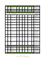


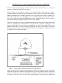


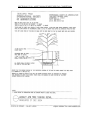


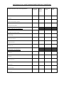


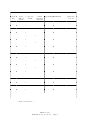


![1127117 - [PROJECT.TOC] - Performance Heating & Plumbing](http://vs1.manualzilla.com/store/data/005895106_1-55e9d6c83dbc31a8ba61d6bb401245cf-150x150.png)