1
AWG DEMO RANGE - FT AP HILL, VA
010003E
PROJECT TABLE OF CONTENTS
DIVISION 01 - GENERAL REQUIREMENTS
01
01
01
01
01
01
01
01
01
01
01
01
01
01
01
01
01
01
01
01
11
30
30
31
32
33
33
35
35
42
45
45
45
50
57
62
74
78
78
91
00
00.10
00.20
19.00
01.00
00
29
26
40.00
00
00.10
04.00
35
02.00
23
35
19
00
23
00
50
50
50
50
20
10
50
50
SUMMARY OF WORK
PROJECT WORK REQUIREMENTS AND RESTRICTIONS
ADMINISTRATIVE REQUIREMENTS
PROJECT MEETINGS
PROJECT SCHEDULE
SUBMITTAL PROCEDURES
LEED(TM) DOCUMENTATION
GOVERNMENTAL SAFETY REQUIREMENTS
ENVIRONMENTAL MANAGEMENT
SOURCES FOR REFERENCE PUBLICATIONS
QUALITY CONTROL SYSTEM (QCS)
CONTRACTOR QUALITY CONTROL
SPECIAL INSPECTION
TEMPORARY CONSTRUCTION FACILITIES
TEMPORARY STORM WATER POLLUTION CONTROL
RECYCLED / RECOVERED MATERIALS
CONSTRUCTION AND DEMOLITION WASTE MANAGEMENT
CLOSEOUT SUBMITTALS
OPERATION AND MAINTENANCE DATA
COMMISSIONING
DIVISION 03 - CONCRETE
03
03
03
03
03
11
15
20
31
40
13.00
13.00
01.00
00.00
00.00
10
10
10
10
10
STRUCTURAL CONCRETE FORMWORK
EXPANSION JOINTS, CONTRACTION JOINTS, AND WATERSTOPS
CONCRETE REINFORCEMENT
CAST-IN-PLACE STRUCTURAL CONCRETE
PLANT-PRECAST CONCRETE PRODUCTS FOR BELOW GRADE
CONSTRUCTION
DIVISION 04 - MASONRY
04 20 00
MASONRY
DIVISION 05 - METALS
05
05
05
05
12
45
50
52
00
00
13
00
STRUCTURAL STEEL
PRE-ENGINEERED LIGHT GAUGE STEEL TRUSSES
MISCELLANEOUS METAL FABRICATIONS
METAL RAILINGS
DIVISION 06 - WOOD, PLASTICS, AND COMPOSITES
06 10 00
06 20 00
ROUGH CARPENTRY
FINISH CARPENTRY
DIVISION 07 - THERMAL AND MOISTURE PROTECTION
07
07
07
07
07
21
21
60
61
92
13
16
00
14.00 20
00
BOARD AND BLOCK INSULATION
MINERAL FIBER BLANKET INSULATION
FLASHING AND SHEET METAL
STEEL STANDING SEAM ROOFING
JOINT SEALANTS
DIVISION 08 - OPENINGS
PROJECT TABLE OF CONTENTS Page 1
AWG DEMO RANGE - FT AP HILL, VA
08
08
08
08
08
11
51
71
81
91
13
13
00
00
00
010003E
STEEL DOORS AND FRAMES
ALUMINUM WINDOWS
DOOR HARDWARE
GLAZING
METAL WALL LOUVERS
DIVISION 09 - FINISHES
09
09
09
09
22
29
67
90
00
00
23.14
00
SUPPORTS FOR PLASTER AND GYPSUM BOARD
GYPSUM BOARD
CHEMICAL RESISTIVE RESINOUS FLOORING
PAINTS AND COATINGS
DIVISION 10 - SPECIALTIES
10
10
10
10
10
14
14
22
28
44
01
02
13
13
16
EXTERIOR SIGNAGE
INTERIOR SIGNAGE
WIRE MESH PARTITIONS
TOILET ACCESSORIES
FIRE EXTINGUISHERS
DIVISION 22 - PLUMBING
22 00 00
PLUMBING, GENERAL PURPOSE
DIVISION 23 - HEATING, VENTILATING, AND AIR CONDITIONING
23
23
23
23
00
05
82
82
00
93.00 10
00.00 20
02.00 10
AIR SUPPLY, DISTRIBUTION, VENTILATION, AND EXHAUST SYSTEMS
TESTING, ADJUSTING, AND BALANCING OF HVAC SYSTEMS
ELECTRIC INFRARED HEATING UNITS
UNITARY HEATING AND COOLING EQUIPMENT
DIVISION 26 - ELECTRICAL
26
26
26
26
20
41
51
56
00
01.00 10
00
00
INTERIOR DISTRIBUTION SYSTEM
LIGHTNING PROTECTION SYSTEM
INTERIOR LIGHTING
EXTERIOR LIGHTING
DIVISION 27 - COMMUNICATIONS
27 10 00
27 51 16
BUILDING TELECOMMUNICATIONS CABLING SYSTEM
RADIO AND PUBLIC ADDRESS SYSTEMS
DIVISION 31 - EARTHWORK
31
31
31
31
31
00
05
11
31
32
00
19
00
16.19
11
EARTHWORK
GEOTEXTILE
CLEARING AND GRUBBING
TERMITE CONTROL BARRIER SYSTEM
SOIL SURFACE EROSION CONTROL
DIVISION 32 - EXTERIOR IMPROVEMENTS
32
32
32
32
15
31
32
92
00
13
23
19
AGGREGATE SURFACE COURSE
CHAIN LINK FENCES AND GATES
SEGMENTAL CONCRETE BLOCK RETAINING WALL
SEEDING
PROJECT TABLE OF CONTENTS Page 2
AWG DEMO RANGE - FT AP HILL, VA
DIVISION 33 - UTILITIES
33
33
33
33
40
46
70
82
00
13
02.00 10
00
STORM DRAINAGE UTILITIES
FOUNDATION DRAINAGE SYSTEM
ELECTRICAL DISTRIBUTION SYSTEM, UNDERGROUND
TELECOMMUNICATIONS OUTSIDE PLANT (OSP)
-- End of Project Table of Contents --
PROJECT TABLE OF CONTENTS Page 3
010003E
AWG DEMO RANGE - FT AP HILL, VA
010003E
SECTION 07 21 13
BOARD AND BLOCK INSULATION
04/06
PART 1
1.1
GENERAL
REFERENCES
The publications listed below form a part of this specification to the
extent referenced. The publications are referred to within the text by the
basic designation only.
ASTM INTERNATIONAL (ASTM)
ASTM C 1289
(2008) Standard Specification for Faced
Rigid Cellular Polyisocyanurate Thermal
Insulation Board
ASTM C 203
(2005a) Breaking Load and Flexural
Properties of Block-Type Thermal Insulation
ASTM C 930
(2005) Potential Health and Safety
Concerns Associated with Thermal
Insulation Materials and Accessories
ASTM E 136
(2009) Behavior of Materials in a Vertical
Tube Furnace at 750 Degrees C
ASTM E 84
(2009c) Standard Test Method for Surface
Burning Characteristics of Building
Materials
ASTM E 96/E 96M
(2005) Standard Test Methods for Water
Vapor Transmission of Materials
NATIONAL FIRE PROTECTION ASSOCIATION (NFPA)
NFPA 211
(2010) Chimneys, Fireplaces, Vents, and
Solid Fuel-Burning Appliances
NFPA 54
(2008) National Fuel Gas Code
NFPA 70
(2008; AMD 1 2008) National Electrical
Code - 2008 Edition
1.2
SUBMITTALS
Government approval is required for submittals with a "G" designation;
submittals not having a "G" designation are for information only. When
used, a designation following the "G" designation identifies the office
that will review the submittal for the Government. The following shall be
submitted in accordance with Section 01 33 00 SUBMITTAL PROCEDURES:
SD-03 Product Data
Block or board insulation; G
SECTION 07 21 13
Page 1
AWG DEMO RANGE - FT AP HILL, VA
010003E
Protection board or coating
Accessories
SD-08 Manufacturer's Instructions
Block or Board Insulation
Adhesive
1.3
1.3.1
DELIVERY, STORAGE, AND HANDLING
Delivery
Deliver materials to the site in original sealed wrapping bearing
manufacturer's name and brand designation, specification number, type,
grade, R-value, and class. Store and handle to protect from damage. Do
not allow insulation materials to become wet, soiled, crushed, or covered
with ice or snow. Comply with manufacturer's recommendations for handling,
storing, and protecting of materials before and during installation.
1.3.2
Storage
Inspect materials delivered to the site for damage; unload and store out of
weather in manufacturer's original packaging. Store only in dry locations,
not subject to open flames or sparks, and easily accessible for inspection
and handling.
1.4
1.4.1
SAFETY PRECAUTIONS
Safety Considerations
Consider safety concerns and measures as outlined in ASTM C 930.
PART 2
2.1
PRODUCTS
BLOCK OR BOARD INSULATION
Provide only thermal insulating materials recommended by manufacturer for
type of application indicated. Provide board or block thermal insulation
conforming to the following standards and the physical properties listed
below:
e.
Faced Rigid Cellular Polyisocyanurate and Polyurethane Insulation:
ASTM C 1289
1. Type I Aluminum Foil on both major surfaces.
Non-reinforced core foam.
Class 1 -
- OR 2. Type II Fibrous felt or glass fiber mat membrane on both major
surfaces of the core foam.
2.1.1
Thermal Resistance
As indicated on drawings.
SECTION 07 21 13
Page 2
AWG DEMO RANGE - FT AP HILL, VA
2.1.2
010003E
2.1.3
Fire Protection Requirement
a.
Flame spread index of 75 or less when tested in accordance with
ASTM E 84.
b.
Smoke developed index of 200 or less when tested in accordance
with ASTM E 84.
Other Material Properties
Provide thermal insulating materials with the following properties:
2.1.4
a.
Flexural strength:
to ASTM C 203.
Not less than 25 psi when measured according
b.
Water Vapor Permeance: Not more than 1.1 Perms or less when
measured according to ASTM E 96/E 96M, desiccant method, in the
thickness required to provide the specified thermal resistance,
including facings, if any.
Recycled Materials
Provide thermal insulation containing recycled materials to the extent
practicable, provided that the material meets all other requirements of
this section. The minimum required recycled material contents (by weight,
not volume) are:
Polyisocyanurate/Polyurethane:
2.1.5
9 percent
Prohibited Materials
Do not provide materials containing more than one percent of asbestos.
2.2
PROTECTION BOARD OR COATING
As recommended by insulation manufacturer.
2.3
2.3.1
ACCESSORIES
Adhesive
As recommended by insulation manufacturer.
2.3.2
Mechanical Fasteners
Corrosion resistant fasteners as recommended by the insulation manufacturer.
PART 3
3.1
EXECUTION
EXISTING CONDITIONS
Before installing insulation, ensure that all areas that will be in contact
with the insulation are dry and free of projections which could cause
voids, compressed insulation, or punctured vapor retarders. If installing
perimeter or under slab insulation, check that the fill is flat, smooth,
dry, and well tamped. If moisture or other conditions are found that do not
allow the proper installation of the insulation, do not proceed but notify
the Contracting Officer of such conditions.
SECTION 07 21 13
Page 3
AWG DEMO RANGE - FT AP HILL, VA
3.2
3.2.1
010003E
PREPARATION
Blocking Around Heat Producing Devices
Unless using insulation board that passes ASTM E 136 in addition to the
requirements in Part 2, install non-combustible blocking around heat
producing devices to provide the following clearances:
a.
Recessed lighting fixtures, including wiring compartments,
ballasts, and other heat producing devices, unless certified for
installation surrounded by insulation: 3 inches from outside face
of fixtures and devices or as required by NFPA 70and, if
insulation is to be placed above fixture or device, 24 inches
above fixture.
b.
Masonry chimneys or masonry enclosing a flue: 2 inches from
outside face of masonry. Masonry chimneys for medium and high
heat operating appliances: Minimum clearances required by NFPA 211.
c.
Vents and vent connectors used for venting products of combustion,
flues, and chimneys other than masonry chimneys: minimum
clearances as required by NFPA 211.
f.
Gas Fired Appliances:
Clearances as required in NFPA 54.
Blocking is not required if chimneys or flues are certified by the
Manufacturer for use in contact with insulating materials.
3.3
3.3.1
INSTALLATION
Insulation Board
Install and handle insulation in accordance with the manufacturer's
installation instructions. Keep material dry and free of extraneous
materials. Observe safe work practices.
3.3.2
Electrical Wiring
Do not install insulation in a manner that would sandwich electrical wiring
between two layers of insulation.
3.3.3
Cold Climate Requirement
Place insulation to the outside of pipes.
3.3.4
Continuity of Insulation
Butt tightly against adjoining boards, studs, rafters, joists, sill plates,
headers and obstructions. Provide continuity and integrity of insulation
at corners, wall to ceiling joint, roof, and floor. Avoid creating any
thermal bridges or voids.
3.4
3.4.1
INSTALLATION ON WALLS
Installation using Furring Strips
Install insulation between members as recommended by insulation
manufacturer.
SECTION 07 21 13
Page 4
AWG DEMO RANGE - FT AP HILL, VA
3.5
010003E
PERIMETER AND UNDER SLAB INSULATION
Install perimeter thermal insulation where heated spaces are adjacent to
exterior walls or slab edges in slab-on-grade or floating-slab construction.
3.5.1
Manufacturer's Instructions
Install, attach, tape edges, provide vapor retarder and other requirements
such as protection against vermin, insects, damage during construction as
recommended in manufacturer's instructions.
3.5.2
Insulation on Vertical Surfaces
Install thermal insulation as indicated.
3.5.3
Protection of Insulation
Protect insulation on vertical surfaces from damage during construction and
back filling by application of protection board or coating. Do not leave
installed vertical insulation unprotected overnight. Install protection
over entire exposed exterior insulation board.
3.6
ACCESS PANELS AND DOORS
Affix insulation to all access panels greater than one square foot and all
access doors in insulated floors and ceilings. Use insulation with same
R-Value as that for floor or ceiling.
-- End of Section --
SECTION 07 21 13
Page 5
AWG DEMO RANGE - FT AP HILL, VA
010003E
SECTION 07 21 16
MINERAL FIBER BLANKET INSULATION
04/06
PART 1
1.1
GENERAL
REFERENCES
The publications listed below form a part of this specification to the
extent referenced. The publications are referred to within the text by the
basic designation only.
ASTM INTERNATIONAL (ASTM)
ASTM C 665
(2006) Mineral-Fiber Blanket Thermal
Insulation for Light Frame Construction
and Manufactured Housing
ASTM C 930
(2005) Potential Health and Safety
Concerns Associated with Thermal
Insulation Materials and Accessories
ASTM E 136
(2009) Behavior of Materials in a Vertical
Tube Furnace at 750 Degrees C
ASTM E 84
(2009c) Standard Test Method for Surface
Burning Characteristics of Building
Materials
NATIONAL FIRE PROTECTION ASSOCIATION (NFPA)
NFPA 211
(2010) Chimneys, Fireplaces, Vents, and
Solid Fuel-Burning Appliances
NFPA 54
(2008) National Fuel Gas Code
NFPA 70
(2008; AMD 1 2008) National Electrical
Code - 2008 Edition
U.S. NATIONAL ARCHIVES AND RECORDS ADMINISTRATION (NARA)
29 CFR 1910.134
1.2
Respiratory Protection
SUBMITTALS
Government approval is required for submittals with a "G" designation;
submittals not having a "G" designation are for information only. When
used, a designation following the "G" designation identifies the office
that will review the submittal for the Government. The following shall be
submitted in accordance with Section 01 33 00 SUBMITTAL PROCEDURES:
SD-03 Product Data
Blanket insulation; G
Accessories; G
SECTION 07 21 16
Page 1
AWG DEMO RANGE - FT AP HILL, VA
010003E
SD-08 Manufacturer's Instructions
Insulation; G
1.3
1.3.1
DELIVERY, STORAGE, AND HANDLING
Delivery
Deliver materials to site in original sealed wrapping bearing
manufacturer's name and brand designation, specification number, type,
grade, R-value, and class. Store and handle to protect from damage. Do
not allow insulation materials to become wet, soiled, crushed, or covered
with ice or snow. Comply with manufacturer's recommendations for handling,
storing, and protecting of materials before and during installation.
1.3.2
Storage
Inspect materials delivered to the site for damage; unload and store out of
weather in manufacturer's original packaging. Store only in dry locations,
not subject to open flames or sparks, and easily accessible for inspection
and handling.
1.4
1.4.1
SAFETY PRECAUTIONS
Respirators
Provide installers with dust/mist respirators, training in their use, and
protective clothing, all approved by National Institute for Occupational
Safety and Health (NIOSH)/Mine Safety and Health Administration (MSHA) in
accordance with 29 CFR 1910.134.
1.4.2
Smoking
Do not smoke during installation of blanket thermal insulation.
1.4.3
Other Safety Concerns
Consider other safety concerns and measures as outlined in ASTM C 930.
PART 2
2.1
PRODUCTS
BLANKET INSULATION
ASTM C 665, Type I, blankets without membrane coverings with a flame spread
rating of 75 or less and a smoke developed rating of 150 or less when
tested in accordance with ASTM E 84.
2.1.1
Thermal Resistance Value (R-VALUE)
As indicated on drawings.
2.1.2
Recycled Materials
Provide Thermal Insulation containing recycled materials to the extent
practicable, provided the material meets all other requirements of this
section. The minimum required recycled materials content by weight are:
Rock Wool:
75 percent slag
SECTION 07 21 16
Page 2
AWG DEMO RANGE - FT AP HILL, VA
Fiberglass:
2.1.3
010003E
20 to 25 percent glass cullet
Prohibited Materials
Do not provide asbestos-containing materials.
2.2
BLOCKING
Wood, metal, unfaced mineral fiber blankets in accordance with ASTM C 665,
Type I, or other approved materials. Use only non-combustible materials
meeting the requirements of ASTM E 136 for blocking around chimneys and
heat producing devices.
2.3
2.3.1
ACCESSORIES
Adhesive
As recommended by the insulation manufacturer.
2.3.2
Mechanical Fasteners
Corrosion resistant fasteners as recommended by the insulation manufacturer.
2.3.3
Wire Mesh
Corrosion resistant and as recommended by the insulation manufacturer.
PART 3
3.1
EXECUTION
EXISTING CONDITIONS
Before installing insulation, ensure that areas that will be in contact
with the insulation are dry and free of projections which could cause
voids, compressed insulation, or punctured vapor retarders. If moisture or
other conditions are found that do not allow the workmanlike installation
of the insulation, do not proceed but notify Contracting Officer of such
conditions.
3.2
3.2.1
PREPARATION
Blocking at Attic Vents and Access Doors
Prior to installation of insulation, install permanent blocking to prevent
insulation from slipping over, clogging, or restricting air flow through
soffit vents at eaves. Install permanent blocking to maintain
accessibility to equipment or controls that require maintenance or
adjustment.
3.2.2
Blocking Around Heat Producing Devices
Install non-combustible blocking around heat producing devices to provide
the following clearances:
a.
Recessed lighting fixtures, including wiring compartments,
ballasts, and other heat producing devices, unless these are
certified by the manufacturer for installation surrounded by
insulation: 3 inches from outside face of fixtures and devices or
as required by NFPA 70 and, if insulation is to be placed above
fixture or device, 24 inches above fixture.
SECTION 07 21 16
Page 3
AWG DEMO RANGE - FT AP HILL, VA
010003E
b.
Vents and vent connectors used for venting the products of
combustion, flues, and chimneys other than masonry chimneys:
Minimum clearances as required by NFPA 211.
c.
Gas Fired Appliances:
Clearances as required in NFPA 54.
Blocking around flues and chimneys is not required when insulation blanket,
including any attached vapor retarder, passed ASTM E 136, in addition to
meeting all other requirements stipulated in Part 2. Blocking is also not
required if the chimneys are certified by the manufacturer for use in
contact with insulating materials.
3.3
INSTALLATION
3.3.1
Insulation
Install and handle insulation in accordance with manufacturer's
instructions. Keep material dry and free of extraneous materials.
personal protective clothing and respiratory equipment is used as
required. Observe safe work practices.
3.3.1.1
Ensure
Electrical wiring
Do not install insulation in a manner that would sandwich electrical wiring
between two layers of insulation.
3.3.1.2
Continuity of Insulation
Install blanket insulation to butt tightly against adjoining blankets and
to studs, rafters, joists, sill plates, headers and any obstructions.
Where insulation required is thicker than depth of joist, provide full
width blankets to cover across top of joists. Provide continuity and
integrity of insulation at corners, wall to ceiling joints, roof, and
floor. Avoid creating thermal bridges.
3.3.1.3
Installation at Bridging and Cross Bracing
Insulate at bridging and cross bracing by splitting blanket vertically at
center and packing one half into each opening. Butt insulation at bridging
and cross bracing; fill in bridged area with loose or scrap insulation.
3.3.1.4
Cold Climate Requirement
Place insulation to the outside of pipes.
3.3.1.5
Insulation without Affixed Vapor Retarder
Provide snug friction fit to hold insulation in place. Stuff pieces of
insulation into cracks between trusses, joists, studs and other framing,
such as at attic access doors, door and window heads, jambs, and sills,
band joists, and headers.
3.3.1.6
Sizing of Blankets
Provide only full width blankets when insulating between trusses, joists,
or studs. Size width of blankets for a snug fit where trusses, joists or
studs are irregularly spaced.
SECTION 07 21 16
Page 4
AWG DEMO RANGE - FT AP HILL, VA
3.3.1.7
010003E
Special Requirements for Ceilings
Place insulation under electrical wiring occurring across joists. Pack
insulation into narrowly spaced framing. Do not block flow of air through
soffit vents.
3.3.1.8
Access Panels and Doors
Affix blanket insulation to access panels greater than one square foot and
access doors in insulated floors and ceilings. Use insulation with same
R-Value as that for floor or ceiling.
-- End of Section --
SECTION 07 21 16
Page 5
AWG DEMO RANGE - FT AP HILL, VA
010003E
SECTION 07 60 00
FLASHING AND SHEET METAL
08/08
PART 1
1.1
GENERAL
REFERENCES
The publications listed below form a part of this specification to the
extent referenced. The publications are referred to within the text by the
basic designation only.
AMERICAN WELDING SOCIETY (AWS)
AWS D1.2/D1.2M
(2008) Structural Welding Code - Aluminum
ASTM INTERNATIONAL (ASTM)
ASTM A 167
(1999; R 2009) Standard Specification for
Stainless and Heat-Resisting
Chromium-Nickel Steel Plate, Sheet, and
Strip
ASTM A 308/A 308M
(2006) Standard Specification for Steel
Sheet, Terne (Lead-Tin Alloy) Coated by
the Hot Dip Process
ASTM B 209
(2007) Standard Specification for Aluminum
and Aluminum-Alloy Sheet and Plate
ASTM B 221
(2008) Standard Specification for Aluminum
and Aluminum-Alloy Extruded Bars, Rods,
Wire, Profiles, and Tubes
ASTM B 32
(2008) Standard Specification for Solder
Metal
ASTM B 370
(2009) Standard Specification for Copper
Sheet and Strip for Building Construction
ASTM B 69
(2008) Standard Specification for Rolled
Zinc
ASTM D 1784
(2008) Standard Specification for Rigid
Poly(Vinyl Chloride) (PVC) Compounds and
Chlorinated Poly(Vinyl Chloride) (CPVC)
Compounds
ASTM D 4586
(2007) Asphalt Roof Cement, Asbestos-Free
SHEET METAL AND AIR CONDITIONING CONTRACTORS' NATIONAL ASSOCIATION
(SMACNA)
SMACNA 1793
(2006) Architectural Sheet Metal Manual,
Sixth Edition, Second Printing
SECTION 07 60 00
Page 1
AWG DEMO RANGE - FT AP HILL, VA
1.2
010003E
GENERAL REQUIREMENTS
Finished sheet metalwork will form a weathertight construction without
waves, warps, buckles, fastening stresses or distortion, which allows for
expansion and contraction. Sheet metal mechanic is responsible for
cutting, fitting, drilling, and other operations in connection with sheet
metal required to accommodate the work of other trades. Coordinate
installation of sheet metal items used in conjunction with roofing with
roofing work to permit continuous roofing operations.
1.3
SUBMITTALS
Government approval is required for submittals with a "G" designation;
submittals not having a "G" designation are for information only. When
used, a designation following the "G" designation identifies the office
that will review the submittal for the Government. Submit the following in
accordance with Section 01 33 00 SUBMITTAL PROCEDURES:
SD-02 Shop Drawings
Covering on flat, sloped, or curved surfaces; G
Gravel stops and fascias; G
Flashing at roof penetrations; G
Drip edge; G
Open valley flashing; G
Eave flashing; G
Indicate thicknesses, dimensions, fastenings and anchoring
methods, expansion joints, and other provisions necessary for
thermal expansion and contraction. Scaled manufacturer's catalog
data may be submitted for factory fabricated items.
SD-11 Closeout Submittals
Quality Control Plan
Submit for sheet metal work in accordance with paragraph entitled
"Field Quality Control."
1.4
DELIVERY, HANDLING, AND STORAGE
Package and protect materials during shipment. Uncrate and inspect
materials for damage, dampness, and wet-storage stains upon delivery to the
job site. Remove from the site and replace damaged materials that cannot
be restored to like-new condition. Handle sheet metal items to avoid
damage to surfaces, edges, and ends. Store materials in dry,
weather-tight, ventilated areas until immediately before installation.
PART 2
2.1
PRODUCTS
MATERIALS
Do not use lead, lead-coated metal, or galvanized steel. Use any metal
listed by SMACNA Arch. Manual for a particular item, unless otherwise
SECTION 07 60 00
Page 2
AWG DEMO RANGE - FT AP HILL, VA
010003E
specified or indicated. Conform to the requirements specified and to the
thicknesses and configurations established in SMACNA Arch. Manual for the
materials. Different items need not be of the same metal, except that if
copper is selected for any exposed item, all exposed items must be copper.
Furnish sheet metal items in 8 to 10 foot lengths. Single pieces less than
8 feet long may be used to connect to factory-fabricated inside and outside
corners, and at ends of runs. Factory fabricate corner pieces with minimum
12 inch legs. Provide accessories and other items essential to complete
the sheet metal installation. Provide accessories made of the same or
compatible materials as the items to which they are applied. Fabricate
sheet metal items of the materials specified below and to the gage,
thickness, or weight shown in Table I at the end of this section. Provide
sheet metal items with mill finish unless specified otherwise. Where more
than one material is listed for a particular item in Table I, each is
acceptable and may be used except as follows:
2.1.1
Exposed Sheet Metal Items
Must be of the same material. Consider the following as exposed sheet
metal: gutters, including hangers; downspouts; gravel stops and fascias;
cap, valley, stepped, base, and eave flashings and related accessories.
2.1.2
Drainage
Do not use copper for an exposed item if drainage from that item will pass
over exposed masonry, stonework or other metal surfaces. In addition to
the metals listed in Table I, lead-coated copper may be used for such items.
2.1.3
Copper, Sheet and Strip
ASTM B 370, cold-rolled temper, H 00 (standard).
2.1.4
Zinc Sheet and Strip
ASTM B 69, Type I, a minimum of 0.024 inch thick.
2.1.5
Stainless Steel
ASTM A 167, Type 302 or 304, 2D Finish, fully annealed, dead-soft temper.
2.1.6
Terne-Coated Steel
Minimum of 14 by 20 inch with minimum of 40 pound coating per double base
box. ASTM A 308/A 308M.
2.1.7
Aluminum Alloy Sheet and Plate
ASTM B 209, form alloy, and temper appropriate for use.
2.1.7.1
Finish
Exposed exterior sheet metal items of aluminum must have a baked-on,
factory-applied color coating of polyvinylidene fluoride (PVF2) or other
equivalent fluorocarbon coating applied after metal substrates have been
cleaned and pretreated. Provide finish coating dry-film thickness of 0.8
to 1.3 mils, and color as indicated on drawings.
SECTION 07 60 00
Page 3
AWG DEMO RANGE - FT AP HILL, VA
2.1.8
010003E
Aluminum Alloy, Extruded Bars, Rods, Shapes, and Tubes
ASTM B 221.
2.1.9
Solder
ASTM B 32, 95-5 tin-antimony.
2.1.10
Polyvinyl Chloride Reglet
ASTM D 1784, Type II, Grade 1, Class 14333-D, 0.075 inch minimum thickness.
2.1.11
Bituminous Plastic Cement
ASTM D 4586, Type I.
2.1.12
Fasteners
Use the same metal or a metal compatible with the item fastened.
stainless steel fasteners to fasten dissimilar materials.
PART 3
3.1
3.1.1
Use
EXECUTION
INSTALLATION
Workmanship
Make lines and angles sharp and true. Free exposed surfaces from visible
wave, warp, buckle, and tool marks. Fold back exposed edges neatly to form
a 1/2 inch hem on the concealed side. Make sheet metal exposed to the
weather watertight with provisions for expansion and contraction.
Make surfaces to receive sheet metal plumb and true, clean, even, smooth,
dry, and free of defects and projections. For installation of items not
shown in detail or not covered by specifications conform to the applicable
requirements of SMACNA 1793, Architectural Sheet Metal Manual. Provide
sheet metal flashing in the angles formed where roof decks abut walls,
curbs, ventilators, pipes, or other vertical surfaces and wherever
indicated and necessary to make the work watertight. Join sheet metal
items together as shown in Table II.
3.1.2
Nailing
Confine nailing of sheet metal generally to sheet metal having a maximum
width of 18 inch. Confine nailing of flashing to one edge only. Space
nails evenly not over 3 inch on center and approximately 1/2 inch from edge
unless otherwise specified or indicated. Face nailing will not be
permitted. Where sheet metal is applied to other than wood surfaces,
include in shop drawings, the locations for sleepers and nailing strips
required to secure the work.
3.1.3
Cleats
Provide cleats for sheet metal 18 inch and over in width. Space cleats
evenly not over 12 inch on center unless otherwise specified or indicated.
Unless otherwise specified, provide cleats of 2 inch wide by 3 inch long
and of the same material and thickness as the sheet metal being installed.
Secure one end of the cleat with two nails and the cleat folded back over
the nailheads. Lock the other end into the seam. Where the fastening is
SECTION 07 60 00
Page 4
AWG DEMO RANGE - FT AP HILL, VA
010003E
to be made to concrete or masonry, use screws and drive in expansion
shields set in concrete or masonry. Pretin cleats for soldered seams.
3.1.4
Bolts, Rivets, and Screws
Install bolts, rivets, and screws where indicated or required. Provide
compatible washers where required to protect surface of sheet metal and to
provide a watertight connection. Provide mechanically formed joints in
aluminum sheets 0.040 inch or less in thickness.
3.1.5
Seams
Straight and uniform in width and height with no solder showing on the face.
3.1.5.1
Flat-lock Seams
Finish not less than 3/4 inch wide.
3.1.5.2
Lap Seams
Finish soldered seams not less than one inch wide.
soldered, not less than 3 inch.
3.1.5.3
Overlap seams not
Loose-Lock Expansion Seams
Not less than 3 inch wide; provide minimum one inch movement within the
joint. Completely fill the joints with the specified sealant, applied at
not less than 1/8 inch thick bed.
3.1.5.4
Flat Seams
Make seams in the direction of the flow.
3.1.6
Soldering
Where soldering is specified, apply to copper, terne-coated stainless
steel, zinc-coated steel, and stainless steel items. Pretin edges of sheet
metal before soldering is begun. Seal the joints in aluminum sheets of
0.040 inch or less in thickness with specified sealants. Do not solder
aluminum.
3.1.6.1
Edges
Flux brush the seams in before soldering. Treat with soldering acid flux
the edges of stainless steel to be pretinned. Seal the joints in aluminum
sheets of 0.040 inch or less in thickness with specified sealants. Do not
solder aluminum.
3.1.7
Welding and Mechanical Fastening
Use welding for aluminum of thickness greater than 0.040 inch. Aluminum
0.040 inch or less in thickness must be butted and the space backed with
formed flashing plate; or lock joined, mechanically fastened, and filled
with sealant as recommended by the aluminum manufacturer.
3.1.7.1
Welding of Aluminum
Use welding of the inert gas, shield-arc type. For procedures, appearance
and quality of welds, and the methods used in correcting welding work,
SECTION 07 60 00
Page 5
AWG DEMO RANGE - FT AP HILL, VA
010003E
conform to AWS D1.2/D1.2M.
3.1.7.2
Mechanical Fastening of Aluminum
Use No. 12, aluminum alloy, sheet metal screws or other suitable aluminum
alloy or stainless steel fasteners. Drive fasteners in holes made with a
No. 26 drill in securing side laps, end laps, and flashings. Space
fasteners 12 inch maximum on center. Where end lap fasteners are required
to improve closure, locate the end lap fasteners not more than 2 inch from
the end of the overlapping sheet.
3.1.8
3.1.8.1
Protection from Contact with Dissimilar Materials
Copper or Copper-bearing Alloys
Paint with heavy-bodied bituminous paint surfaces in contact with
dissimilar metal, or separate the surfaces by means of moistureproof
building felts.
3.1.8.2
Aluminum
Do not allow aluminum surfaces in direct contact with other metals except
stainless steel, zinc, or zinc coating. Where aluminum contacts another
metal, paint the dissimilar metal with a primer followed by two coats of
aluminum paint. Where drainage from a dissimilar metal passes over
aluminum, paint the dissimilar metal with a non-lead pigmented paint.
3.1.8.3
Metal Surfaces
Paint surfaces in contact with mortar, concrete, or other masonry materials
with alkali-resistant coatings such as heavy-bodied bituminous paint.
3.1.8.4
Wood or Other Absorptive Materials
Paint surfaces that may become repeatedly wet and in contact with metal
with two coats of aluminum paint or a coat of heavy-bodied bituminous paint.
3.1.9
Expansion and Contraction
Provide expansion and contraction joints at not more than 32 foot intervals
for aluminum and at not more than 40 foot intervals for other metals.
Provide an additional joint where the distance between the last expansion
joint and the end of the continuous run is more than half the required
interval. Space joints evenly. Join extruded aluminum gravel stops and
fascias by expansion and contraction joints spaced not more than 12 feet
apart.
3.1.10
Base Flashing
Extend flashing not less than 8 inches and not less than 4 inches under the
roof covering. Where finish wall coverings form a counterflashing, extend
the vertical leg of the flashing up behind the applied wall covering not
less than 6 inches. Overlap the flashing strips with the previously laid
flashing not less than 3 inches. Fasten the strips at their upper edge to
the deck. Horizontal flashing at vertical surfaces must extend vertically
above the roof surface and be fastened at their upper edge to the deck a
minimum of 6 inches on center with large headed aluminum roofing nails or
hex headed, galvanized shielded screws a minimum of 2-inch lap of any
surface. Solder end laps and provide for expansion and contraction.
SECTION 07 60 00
Page 6
AWG DEMO RANGE - FT AP HILL, VA
010003E
Extend the metal flashing over crickets at the up-slope side of curbs, and
similar vertical surfaces extending through sloping roofs. Extend the metal
flashings onto the roof covering not less than 4.5 inches at the lower side
of vertical surfaces extending through the roof decks. Install and fit the
flashings so as to be completely weathertight. Provide factory-fabricated
base flashing for interior and exterior corners.
3.1.11
Metal Drip Edge
Provide a metal drip edge, designed to allow water run-off to drip free of
underlying construction, at eaves and rakes prior to the application of
roofing. Apply directly on the wood deck at the eaves and over the
underlay along the rakes. Extend back from the edge of the deck not more
than 3 inches and secure with compatible nails spaced not more than 10
inches on center along upper edge.
3.1.12
Open Valley Flashing
Provide valley flashing free of longitudinal seams, of width sufficient to
extend not less than 6 inches under the roof covering on each side.
Provide a 1/2 inch fold on each side of the valley flashing. Lap the
sheets not less than 6 inch in the direction of flow and secure to roofing
construction with cleats attached to the fold on each side. Nail the tops
of sheets to roof sheathing. Space the cleats not more than 12 inch on
center. Provide exposed flashing not less than 4 inches in width at the
top and increase one inch in width for each additional 8 feet in length.
Where the slope of the valley is 4.5 inches or less per foot, or the
intersecting roofs are on different slopes, provide an inverted V-joint,
one inch high, along the centerline of the valley; and extend the edge of
the valley sheets 8 inch under the roof covering on each side.
3.1.13
Eave Flashing
One piece in width, applied in 8 to 10 foot lengths with expansion joints
spaced as specified in paragraph entitled "Expansion and Contraction."
Provide a 3/4 inch continuous fold in the upper edge of the sheet to engage
cleats spaced not more than 10 inch on center. Locate the upper edge of
flashing not less than 18 inch from the outside face of the building,
measured along the roof slope. Fold lower edge of the flashing over and
loose-lock into a continuous edge strip on the fascia. Where eave flashing
intersects metal valley flashing, secure with one inch flat locked joints
with cleats that are 10 inch on center.
3.1.14
Sheet Metal Covering on Flat, Sloped, or Curved Surfaces
Except as specified or indicated otherwise, cover and flash all minor flat,
sloped, or curved surfaces such as crickets, bulkheads, dormers and small
decks with metal sheets of the material used for flashing; maximum size of
sheets, 16 by 18 inch. Fasten sheets to sheathing with metal cleats. Lock
seams and solder. Lock aluminum seams as recommended by aluminum
manufacturer. Provide an underlayment of roofing felt for all sheet metal
covering.
3.1.15
Flashing at Roof Penetrations and Equipment Supports
Provide metal flashing for all pipes, ducts, and conduits projecting
through the roof surface and for equipment supports, guy wire anchors, and
similar items supported by or attached to the roof deck.
SECTION 07 60 00
Page 7
AWG DEMO RANGE - FT AP HILL, VA
3.1.16
010003E
Single Pipe Vents
See Table I, footnote (c). Set flange of sleeve in bituminous plastic
cement and nail 3 inch on center. Bend the top of sleeve over and extend
down into the vent pipe a minimum of 2 inch. For long runs or long rises
above the deck, use a two-piece formed metal housing. Set metal housing
with a metal sleeve having a 4 inch roof flange in bituminous plastic
cement and nailed 3 inches on center. Extend sleeve a minimum of 8 inches
above the roof deck and lapped a minimum of 3 inch by a metal hood secured
to the vent pipe by a draw band. Seal the area of hood in contact with
vent pipe with an approved sealant.
3.2
PAINTING
Field-paint sheet metal for separation of dissimilar materials.
3.3
CLEANING
Clean exposed sheet metal work at completion of installation. Remove
grease and oil films, handling marks, contamination from steel wool,
fittings and drilling debris, and scrub-clean. Free the exposed metal
surfaces of dents, creases, waves, scratch marks, and solder or weld marks.
3.4
REPAIRS TO FINISH
Scratches, abrasions, and minor surface defects of finish may be repaired
in accordance with the manufacturer's printed instructions and as approved.
Repair damaged surfaces caused by scratches, blemishes, and variations of
color and surface texture. Replace items which cannot be repaired.
3.5
FIELD QUALITY CONTROL
Establish and maintain a Quality Control Plan for sheet metal used in
conjunction with roofing to assure compliance of the installed sheet
metalwork with the contract requirements. Remove work that is not in
compliance with the contract and replace or correct. Include quality
control, but not be limited to, the following:
3.5.1
a.
Observation of environmental conditions; number and skill level of
sheet metal workers; condition of substrate.
b.
Verification that specified material is provided and installed.
c.
Inspection of sheet metalwork, for proper size(s) and
thickness(es), fastening and joining, and proper installation.
Procedure
Submit for approval prior to start of roofing work. Include a checklist of
points to be observed. Document the actual quality control observations
and inspections. Furnish a copy of the documentation to the Contracting
Officer at the end of each day.
SECTION 07 60 00
Page 8
AWG DEMO RANGE - FT AP HILL, VA
TABLE I.
010003E
SHEET METAL WEIGHTS, THICKNESSES, AND GAGES
Copper,
Ounces
TernePer
Stainless Coated
Sheet Metal Items
Square
Aluminum,
Steel,
Steel,
Foot
Inch
Inch
Inch
___________________________________________________________________________
Covering on minor flat,
pitched or curved
surfaces............
Flashings:
Eave................
Spandrel beam.......
Bond barrier........
Valley..............
Pipe vent sleeve(c)
Edge strip..........
20
.040
.018
.018
16
10
16
16
.032
.015
.010
.015
.015
.015
.010
.015
.015
24
.050
.025
-
(a)
Brass.
(b)
May be polyvinyl chloride.
(c)
2.5 pound minimum lead sleeve with 4 inch flange. Where lead sleeve
is impractical, refer to paragraph entitled "Single Pipe Vents" for
optional material.
TABLE II. SHEET METAL JOINTS
TYPE OF JOINT
Copper, TerneCoated
Item
Steel,
Designa- and
tion
Stainless
Steel
Aluminum
Remarks
______________________________________________________________________
Flashings
Eave
One inch flat
locked, cleated
One inch
loose locked,
expansion
joint cleated
One inch flat
locked, locked,
cleated one inch
loose locked, sealed
expansion joints,
cleated
Same as base
flashing.
Valley.
6 inch lap cleated
6 inch lap cleated
- - -
Edge
strip
Butt
Butt
- - -
(a)
Provide a 3 inch lap elastomeric flashing with manufacturer's
recommended sealant.
(b)
Seal polyvinyl chloride reglet with manufacturer's
SECTION 07 60 00
Page 9
AWG DEMO RANGE - FT AP HILL, VA
010003E
TABLE II. SHEET METAL JOINTS
TYPE OF JOINT
Copper, TerneCoated
Item
Steel,
Designa- and
tion
Stainless
Steel
Aluminum
Remarks
______________________________________________________________________
recommended sealant.
-- End of Section --
SECTION 07 60 00
Page 10
AWG DEMO RANGE - FT AP HILL, VA
010003E
SECTION 07 61 14.00 20
STEEL STANDING SEAM ROOFING
08/08
PART 1
1.1
GENERAL
REFERENCES
The publications listed below form a part of this specification to the
extent referenced. The publications are referred to within the text by the
basic designation only.
AMERICAN IRON AND STEEL INSTITUTE (AISI)
AISI SG03-3
(2002) Cold-Formed Steel Design Manual Set
ASTM INTERNATIONAL (ASTM)
ASTM A 1008/A 1008M
(2009) Standard Specification for Steel,
Sheet, Cold-Rolled, Carbon, Structural,
High-Strength Low-Alloy and High-Strength
Low-Alloy with Improved Formability,
Solution Hardened, and Bake Hardened
ASTM A 366/A 366M
(1997e1) Standard Specification for
Commercial Steel, Sheet, Carbon,(0.15
Maximum Percent Cold-Rolled
ASTM A 570/A 570M
(1998) Standard Specification for Steel,
Sheet and Strip, Carbon, Hot-Rolled
ASTM A 653/A 653M
(2009a) Standard Specification for Steel
Sheet, Zinc-Coated (Galvanized) or
Zinc-Iron Alloy-Coated (Galvannealed) by
the Hot-Dip Process
ASTM A 792/A 792M
(2009) Standard Specification for Steel
Sheet, 55% Aluminum-Zinc Alloy-Coated by
the Hot-Dip Process
ASTM B 117
(2009) Standing Practice for Operating
Salt Spray (Fog) Apparatus
ASTM D 1654
(2008) Evaluation of Painted or Coated
Specimens Subjected to Corrosive
Environments
ASTM D 2244
(2009a) Calculation of Color Tolerances
and Color Differences from Instrumentally
Measured Color Coordinates
ASTM D 2247
(2002) Testing Water Resistance of
Coatings in 100% Relative Humidity
ASTM D 226/D 226M
(2009) Standard Specification for
Asphalt-Saturated Organic Felt Used in
Roofing and Waterproofing
SECTION 07 61 14.00 20
Page 1
AWG DEMO RANGE - FT AP HILL, VA
010003E
ASTM D 4214
(2007) Standard Test Method for Evaluating
the Degree of Chalking of Exterior Paint
Films
ASTM D 522
(1993a; R 2008) Mandrel Bend Test of
Attached Organic Coatings
ASTM D 523
(2008) Standard Test Method for Specular
Gloss
ASTM D 714
(2002; R 2009) Evaluating Degree of
Blistering of Paints
ASTM D 968
(2005e1) Abrasion Resistance of Organic
Coatings by Falling Abrasive
ASTM E 1592
(2005) Structural Performance of Sheet
Metal Roof and Siding Systems by Uniform
Static Air Pressure Difference
ASTM G 23
(1996) Operating Light-Exposure Apparatus
(Carbon-Arc Type) With and Without Water
for Exposure of Nonmetallic Materials
SHEET METAL AND AIR CONDITIONING CONTRACTORS' NATIONAL ASSOCIATION
(SMACNA)
SMACNA 1793
1.2
1.2.1
(2006) Architectural Sheet Metal Manual,
Sixth Edition, Second Printing
DEFINITIONS
Field-Formed Seam
Seams of panels so configured that when adjacent sheets are installed the
seam is sealed utilizing mechanical or hand seamers. Crimped (45 degree
bend), roll formed (180 degree bend), double roll formed (2 - 180 degree
bends), and roll and lock systems are types of field-formed seam systems.
1.2.2
Snap Together Seam
Panels so configured that the male and female portions of the seam
interlock through the application of foot pressure or tamping with a
mallet. Snap-on cap configurations are a type of snap together system.
1.2.3
Pre-Formed
Formed to the final, less field-formed seam, profile and configuration in
the factory.
1.2.4
Field-Formed
Formed to the final, less field-formed seam, profile and configuration at
the site of work prior to installation.
1.2.5
Roofing System
The roofing system is defined as the assembly of roofing components,
SECTION 07 61 14.00 20
Page 2
AWG DEMO RANGE - FT AP HILL, VA
010003E
including roofing panels, flashing, fasteners, and accessories which, when
assembled properly result in a watertight installation.
1.3
SYSTEM DESCRIPTION
1.3.1
Design Requirements
a.
Panels shall be continuous lengths up to manufacturer's standard
longest lengths, with no joints or seams, except where indicated
or specified. Ribs of adjoining sheets shall be in continuous
contact from eave to ridge. Individual panels of snap together
type systems shall be removable for replacement of damaged
material.
b.
There shall be no exposed or penetrating fasteners except where
shown on approved shop drawings. Fasteners into steel shall be
stainless steel, zinc cast head, or cadmium plated steel screws
inserted into predrilled holes. There shall be a minimum of two
fasteners per clip. Single fasteners will be allowed when
supporting structural members are prepunched or predrilled.
c.
Snap together type systems shall have a capillary break and a
positive side lap locking device. Field-formed seam type systems
shall be mechanically locked closed by the manufacturer's locking
tool. The seam shall include a continuous factory applied sealant
when required by the manufacturer to withstand the wind loads
specified.
d.
Roof panel anchor clips shall be concealed and designed to allow
for longitudinal thermal movement of the panels, except where
specific fixed points are indicated. Provide for lateral thermal
movement in panel configuration or with clips designed for lateral
and longitudinal movement.
1.3.2
Design Conditions
The system shall be designed to resist positive and negative loads
specified herein in accordance with the AISI SG03-3. Panels shall support
walking loads without permanent distortion or telegraphing of the
structural supports.
1.3.2.1
Wind Uplift
Roof system and attachments shall resist the loads indicated on the
drawings.
1.3.2.2
Roof Live Loads
Loads shall be applied on the horizontal projection of the roof structure.
The minimum roof design live load shall be 20 psf.
1.3.2.3
Thermal Movement
System shall be capable of withstanding thermal movement based on a
temperature range of 10 degrees F and 140 degrees F.
1.3.2.4
Deflection
Panels shall be capable of supporting design loads between unsupported
SECTION 07 61 14.00 20
Page 3
AWG DEMO RANGE - FT AP HILL, VA
010003E
spans with deflection of not greater than L/180 of the span.
1.3.3
Structural Performance
The structural performance test methods and requirements of the Standing
Seam Roofing Systems (SSRS) shall be in accordance with ASTM E 1592.
1.4
SUBMITTALS
Government approval is required for submittals with a "G" designation;
submittals not having a "G" designation are for information only. When
used, a designation following the "G" designation identifies the office
that will review the submittal for the Government. The following shall be
submitted in accordance with Section 01 33 00 SUBMITTAL PROCEDURES:
SD-02 Shop Drawings
Roofing; G
Submit roofing drawings to supplement the instructions and
diagrams. Drawings shall include design and erection drawings
containing an isometric view of the roof showing the design uplift
pressures and dimensions of edge, ridge and corner zones; and show
typical and special conditions including flashings, materials and
thickness, dimensions, fixing lines, anchoring methods, sealant
locations, sealant tape locations, fastener layout, sizes, and
spacing, terminations, penetrations, attachments, and provisions
for thermal movement. Details of installation shall be in
accordance with the manufacturer's Standard Instructions and
details or the SMACNA 1793. Prior to submitting shop drawings,
have drawings reviewed and approved by the manufacturer's
technical engineering department.
SD-03 Product Data
Roofing panels; G
Attachment clips; G
Closures; G
Accessories; G
Fasteners; G
Sealants; G
Sample warranty certificate; G
Submit for materials to be provided. Submit data sufficient to
indicate conformance to specified requirements.
SD-04 Samples
Roofing panel
Submit a 12 inch long by full width section of typical panel.
For color selection, submit 2 by 4 inch metal samples in color,
SECTION 07 61 14.00 20
Page 4
AWG DEMO RANGE - FT AP HILL, VA
010003E
finish and texture specified or indicated on drawings.
Accessories
Submit each type of accessory item used in the project
including, but not limited to each type of anchor clip, closure,
fastener, and leg clamp.
Sealants
Intermediate Support Section
Submit full size samples of each intermediate support section,
12 inches long.
SD-05 Design Data
Design calculations; G, AE
SD-06 Test Reports
Field Inspection; G
Submit manufacturer's technical representative's field
inspection reports as specified in paragraph entitled
"Manufacturer's Field Inspection."
Structural performance tests
Finish tests
SD-07 Certificates
Manufacturer's Technical Representative's Qualifications
Statement of Installer's Qualifications
Submit documentation from roofing manufacturer proving the
manufacturer's technical representative meets below specified
requirements. Include name, address, telephone number, and
experience record.
Submit documentation proving the installer is factory-trained,
has the specified experience, and authorized by the manufacturer
to install the products specified.
Coil stock compatibility; G
Provide certification of coil compatibility with roll forming
machinery to be used for forming panels without warping, waviness,
and rippling not part of panel profile; to be done without damage,
abrasion or marking of finish coating.
SD-08 Manufacturer's Instructions
Installation manual; G
Submit manufacturers printed installation manual, instructions,
and standard details.
SECTION 07 61 14.00 20
Page 5
AWG DEMO RANGE - FT AP HILL, VA
010003E
SD-11 Closeout Submittals
Information card
For each roofing installation, submit a typewritten card or
photoengraved aluminum card containing the information listed on
Form 1 located at the end of this section.
1.5
DESIGN CALCULATIONS
Provide design calculations prepared by a professional engineer
specializing in structural engineering verifying that system supplied and
any additional framing meets design load criteria indicated. Coordinate
calculations with manufacturer's test results. Include calculations for:
Wind load uplift design pressure at roof locations specified in
paragraph entitled "Wind Uplift."
Clip spacing and allowable load per clip.
Fastening of clips to structure or intermediate supports.
Intermediate support spacing and framing and fastening to
structure when required.
Allowable panel span at anchorage spacing indicated.
Safety factor used in design loading.
Governing code requirements or criteria.
Edge and termination details.
1.6
1.6.1
QUALITY ASSURANCE
Preroofing Conference
After submittals are received and approved but before roofing work,
including associated work, is preformed, the Contracting Officer will hold
a preroofing conference to review the following:
a.
The drawings and specifications
b.
Procedure for on site inspection and acceptance of the roofing
substrate and pertinent structural details relating to the roofing
system
c.
Contractor's plan for coordination of the work of the various
trades involved in providing the roofing system and other
components secured to the roofing
d.
Safety requirements
The preroofing conference shall be attended by the Contractor and personnel
directly responsible for the roofing installation, mechanical and electrical
work, and the roofing manufacturer's technical representative. Conflicts
among those attending the preroofing conference shall be resolved and
confirmed in writing before roofing work, including associated work, is
SECTION 07 61 14.00 20
Page 6
AWG DEMO RANGE - FT AP HILL, VA
010003E
begun. Contractor shall prepare written minutes of the preroofing
conference and submit to the Contracting Officer.
1.6.2
Manufacturer
The SSMRS shall be the product of a metal roofing industry - recognized
manufacturer who has been in the practice of manufacturing SSMRS for a
period of not less than 5 years and who has been involved in at least 5
projects similar in size and complexity to this project.
1.6.3
Manufacturer's Technical Representative
The representative shall have authorization from manufacturer to approve
field changes and be thoroughly familiar with the products and with
installations in the geographical area where construction will take place.
The manufacturer's representative shall be an employee of the manufacturer
with at least 5 years experience in installing the roof system. The
representative shall be available to perform field inspections and attend
meetings as required herein, and as requested by the Contracting Officer.
1.6.4
Installer's Qualifications
The roofing system installer shall be factory-trained, approved by the
metal roofing system manufacturer to install the system, and shall have a
minimum of three years experience as an approved applicator with that
manufacturer. The applicator shall have applied five installations of
similar size and scope as this project within the previous 3 years.
1.6.5
Single Source
Roofing panels, clips, closures, and other accessories shall be standard
products of the same manufacturer; shall be the latest design by the
manufacturer; and shall have been designed by the manufacturer to operate
as a complete system for the intended use.
1.6.6
Laboratory Tests For Panel Finish
The term "appearance of base metal" refers to the metal coating on steel.
Panels shall meet the following test requirements:
a.
Formability Test: When subjected to a 180 degree bend over a 1/8
inch diameter mandrel in accordance with ASTM D 522, exterior
coating film shall show only slight microchecking and no loss of
adhesion.
b.
Accelerated Weathering Test: Withstand a weathering test for a
minimum of 2000 hours in accordance with ASTM G 23, Method 1
without cracking, peeling, blistering, loss of adhesion of the
protective coating, or corrosion of the base metal. Protective
coating that can be readily removed from the base metal with a
penknife blade or similar instrument shall be considered to
indicate loss of adhesion.
c.
Chalking Resistance: After the 2000-hour weatherometer test,
exterior coating shall not chalk greater than No. 8 rating when
measured in accordance with ASTM D 4214 test procedures.
d.
Color Change Test:
SECTION 07 61 14.00 20
Page 7
AWG DEMO RANGE - FT AP HILL, VA
010003E
After the 3000-hour weatherometer test, exterior coating color change
shall not exceed 5 NBS units when measured in accordance with
ASTM D 2244 test procedure.
1.7
e.
Salt Spray Test: Withstand a salt spray test for a minimum of
1000 hours in accordance with ASTM B 117, including the scribe
requirement in the test. Immediately upon removal of the panel
from the test, the coating shall receive a rating of 8, few
blisters in field as determined by ASTM D 714; and an average
rating of 6, 1/8 inch failure at scribe, as determined by
ASTM D 1654. Rating Schedule No. 1.
f.
Abrasion Resistance Test for Color Coating: When subjected to the
falling sand test in accordance with ASTM D 968, coating system
shall withstand a minimum of 50 liters of sand per mil thickness
before appearance of base metal.
g.
Humidity Test: When subjected to a humidity cabinet test in
accordance with ASTM D 2247 for 1000 hours, a scored panel shall
show no signs of blistering, cracking, creepage, or corrosion.
h.
Gloss Test: The gloss of the finish shall be 30 plus or minus 5
at an angle of 60 degrees, when measured in accordance with
ASTM D 523.
WARRANTY
Furnish manufacturer's no-dollar-limit materials and workmanship warranty
for the roofing system. The warranty period shall be not less than 20
years from the date of Government acceptance of the work. The warranty
shall be issued directly to the Government. The warranty shall provide
that if within the warranty period the metal roofing system becomes
non-watertight or shows evidence of corrosion, perforation, rupture or
excess weathering due to deterioration of the roofing system resulting from
defective materials or installed workmanship the repair or replacement of
the defective materials and correction of the defective workmanship shall
be the responsibility of the roofing system manufacturer. Repairs that
become necessary because of defective materials and workmanship while
roofing is under warranty shall be performed within 7 days after
notification, unless additional time is approved by the Contracting
Officer. Failure to perform repairs within the specified period of time
will constitute grounds for having the repairs performed by others and the
cost billed to the manufacturer. The Contractor shall also provide a 2
year contractor installation warranty.
1.8
DELIVERY, STORAGE AND HANDLING
Deliver, store, and handle preformed panels, bulk roofing products and
other manufactured items in a manner to prevent damage or deformation.
1.8.1
Delivery
Provide adequate packaging to protect materials during shipment. Crated
materials shall not be uncrated until ready for use, except for inspection.
Immediately upon arrival of materials at the jobsite, inspect materials for
damage, dampness, and staining. Damaged or permanently stained materials
that cannot be restored to like-new condition shall be replaced with
satisfactory material. If materials are wet, remove the moisture and
re-stack and protect the panels until used.
SECTION 07 61 14.00 20
Page 8
AWG DEMO RANGE - FT AP HILL, VA
1.8.2
010003E
Storage
Stack materials on platforms or pallets and cover with tarpaulins or other
suitable weathertight covering which prevents water trapping or
condensation. Store materials so that water which might have accumulated
during transit or storage will drain off. Do not store the panels in
contact with materials that might cause staining, such as mud, lime,
cement, fresh concrete or chemicals. Protect stored panels from wind
damage.
1.8.3
Handling
Handle material carefully to avoid damage to surfaces, edges and ends.
PART 2
2.1
PRODUCTS
ROOFING PANELS
Panels shall have interlocking ribs for securing adjacent sheets. System
for securing the roof covering to structural framing members shall be
concealed clip fastening system with no fasteners penetrating the panels
except at the ridge or eave, rakes, penetrations, and end laps. Backing
plates and ends of panels at end laps shall be predrilled or prepunched;
factory prepare ends of panels to be lapped by trimming part of seam,
die-setting or swaging ends of panels. Length of sheets shall be
sufficient to cover the entire length of any unbroken roof slope when such
slope is 30 feet or less. When length of run exceeds 30 feet, each sheet
in the run shall extend over two or more spans. Sheets longer than 30 feet
may be furnished if approved by the Contracting Officer. Width of sheets
shall provide not less than 12 inches of coverage in place. Roof panel
profile shall be smooth with a 1 3/4 inch male-femaile interlocking
standing seam. Make provisions for expansion and contraction at either
ridge or eave, consistent with the type of system to be used. Panels from
coil stock shall be formed without warping, waviness or ripples not part of
the panel profile and shall be free of damage to the finish coating system.
2.1.1
Material
Zinc-coated steel conforming to ASTM A 653/A 653M, G90coating designation
or aluminum-zinc alloy coated steel conforming to ASTM A 792/A 792M, AZ 55
coating. Minimum thickness to be 0.023 inch thick (24 gage) minimum except
when mid field of roof is subject to design wind uplift pressures of 60 psf
or greater, entire roof system shall have a minimum thickness of 0.030 inch
(22 gage).
2.1.2
Texture
Smooth with raised intermediate ribs for added stiffness.
2.1.3
Finish
Factory color finish.
2.1.3.1
Factory Color Finish
Provide factory applied, thermally cured coating to exterior and interior
of metal roof and wall panels and metal accessories. Provide exterior
finish top coat of 70 percent resin polyvinyldene fluoride with not less
SECTION 07 61 14.00 20
Page 9
AWG DEMO RANGE - FT AP HILL, VA
010003E
than 0.8 mil dry film thickness. Provide exterior primer with not less
than 0.2 mil dry film thickness. Interior finish shall consist of 0.5 mil
dry film thickness backer coat. Provide exterior coating meeting test
requirements specified below. Tests shall have been performed ohn same
factory finish and thickness provided. Provide clear factory edge coating
on all factory cut or unfinished edges.
2.2
ATTACHMENT CLIPS
Fabricate clips from ASTM A 366/A 366M, ASTM A 570/A 570M, or
ASTM A 1008/A 1008M steel hot-dip galvanized in accordance with
ASTM A 653/A 653M, G 90, or Series 300 stainless steel. Size, shape,
thickness and capacity as required to meet the load, insulation thickness
and deflection criteria specified.
2.3
ACCESSORIES
Sheet metal flashings, trim, moldings, closure strips, pre-formed crickets,
caps, equipment curbs, and other similar sheet metal accessories used in
conjunction with preformed metal panels shall be of the same material as
used for the panels. Provide metal accessories with a factory color finish
to match the roofing panels, except that such items which will be concealed
after installation may be provided without the finish if they are stainless
steel. Metal shall be of a thickness not less than that used for the
panels. Thermal spacer blocks and other thermal barriers at concealed clip
fasteners shall be as recommended by the manufacturer except that wood
spacer blocks are not allowed.
2.3.1
2.3.1.1
Closures
Rib Closures
Corrosion resisting steel, closed-cell or solid-cell synthetic rubber,
neoprene or polyvinyl chloride pre-molded to match configuration of rib
opening. Material for closures shall not absorb water.
2.3.1.2
Ridge Closures
Metal-clad foam or metal closure with foam secondary closure matching panel
configuration for installation on surface of roof panel between panel ribs
at ridge and headwall roof panel flashing conditions and terminations.
Foam material shall not absorb water.
2.3.2
Fasteners
Zinc-coated steel, corrosion resisting steel, zinc cast head, or nylon
capped steel, type and size specified below or as otherwise approved for
the applicable requirements. Design the fastening system to withstand the
design loads specified. Exposed fasteners shall be gasketed or have
gasketed washers on the exterior side of the covering to waterproof the
penetration. Washer material shall be compatible with the covering; have a
minimum diameter of 3/8 inch for structural connections; and gasketed
portion of fasteners or washers shall be neoprene or other equally durable
elastomeric material approximately 1/8 inch thick.
2.3.2.1
Screws
Not smaller than No. 14 diameter if self-tapping type and not smaller than
No. 12 diameter if self-drilling and self-tapping.
SECTION 07 61 14.00 20
Page 10
AWG DEMO RANGE - FT AP HILL, VA
2.3.2.2
010003E
Bolts
Not smaller than 1/4 inch diameter, shouldered or plain shank as required,
with proper nuts.
2.3.2.3
Automatic End-Welded Studs
Automatic end-welded studs shall be shouldered type with a shank diameter
of not smaller than 3/16 inch and cap or nut for holding covering against
the shoulder.
2.3.2.4
Explosive Driven Fasteners
Fasteners for use with explosive actuated tools shall have a shank diameter
of not smaller than 0.145 inch with a shank length of not smaller than 1/2
inch for fastening to steel and not smaller than one inch for fastening to
concrete.
2.3.2.5
Rivets
Blind rivets shall be stainless steel with 1/8 inch nominal diameter shank.
Rivets shall only be used for the fastening of trim. Rivets with hollow
stems shall have closed ends.
2.3.3
Sealants
Elastomeric type containing no oil or asphalt. Exposed sealant shall cure
to a rubberlike consistency. Concealed sealant shall be the non-hardening
type. Seam sealant shall be factory-applied, non-skinning, non-drying, and
shall conform to the roofing manufacturer's recommendations.
Silicone-based sealants shall not be used in contact with finished metal
panels and components unless approved otherwise by the Contracting Officer.
2.3.4
GASKETS AND INSULATING COMPOUNDS
Nonabsorptive and suitable for insulating contact points of incompatible
materials. Insulating compounds shall be nonrunning after drying.
2.4
UNDERLAYMENT FOR WOOD SUBSTRATES
ASTM D 226/D 226M, Type I perforated, covered by water-resistant rosin
sized building paper.
PART 3
3.1
EXECUTION
EXAMINATION
Examine surfaces to receive standing seam metal roofing and flashing.
Ensure that surfaces are plumb and true, clean, even, smooth, as dry and
free from defects and projections which might affect the installation.
3.2
3.2.1
PROTECTION FROM CONTACT WITH DISSIMILAR MATERIALS
Cementitious Materials
Paint metal surfaces which will be in contact with mortar, concrete, or
other masonry materials with one coat of alkali-resistant coating such as
heavy-bodied bituminous paint.
SECTION 07 61 14.00 20
Page 11
AWG DEMO RANGE - FT AP HILL, VA
3.2.2
010003E
Contact with Wood
Where metal will be in contact with wood or other absorbent material
subject to wetting, seal joints with sealing compound and apply one coat of
heavy-bodied bituminous paint.
3.3
INSTALLATION
Install in accordance with the approved manufacturer's erection
instructions, shop drawings, and diagrams. Panels shall be in full and
firm contact with attachment clips. Where prefinished panels are cut in
the field, or where any of the factory applied coverings or coatings are
abraded or damaged in handling or installation, they shall, after necessary
repairs have been made with material of the same color as the weather
coating, be approved before being installed. Completely seal openings
through panels. Correct defects or errors in the materials. Replace
materials which cannot be corrected in an approved manner with nondefective
materials. Provide molded closure strips where indicated and where
necessary to provide weathertight construction. Use shims as required to
ensure attachment clip line is true. Use a spacing gage at each row of
panels to ensure that panel width is not stretched or shortened. Provide
one layer of asphalt-saturated felt placed perpendicular to roof slope,
covered by one layer of rosin-sized building paper placed parallel to roof
slope with side laps down slope and attached with roofing nails. Overlap
side and end laps 3 inches, offset seams in building paper with seams in
felt.
3.3.1
Roof Panels
Apply roofing panels with the standing seams parallel to the slope of the
roof. Provide roofing panels in longest practical lengths from ridge to
eaves (top to eaves on shed roofs), with no transverse joints except at the
junction of ventilators, curbs, and similar openings. Install flashing to
assure positive water drainage away from roof penetrations. Locate panel
end laps such that fasteners do not engage supports or otherwise restrain
the longitudinal thermal movement of panels. Form field-formed seam type
system seams in the field with an automatic mechanical seamer approved by
the manufacturer. Attach panels to the structure with concealed clips
incorporated into panel seams. Clip attachment shall allow roof to move
independently of the structure, except at fixed points as indicated.
3.3.2
Flashings
Provide flashing, related closures and accessories as indicated and as
necessary to provide a weathertight installation. Install flashing to
ensure positive water drainage away from roof penetrations. Flash and seal
the roof at the ridge, eaves and rakes, and projections through the roof.
Place closure strips, flashing, and sealing material in an approved manner
that will assure complete weathertightness. Details of installation which
are not indicated shall be in accordance with the SMACNA 1793, panel
manufacturer's approved printed instructions and details, or the approved
shop drawings. Allow for expansion and contraction of flashing.
3.3.3
Flashing Fasteners
Fastener spacings shall be in accordance with the panel manufacturer's
recommendations and as necessary to withstand the design loads indicated.
Install fasteners in roof valleys as recommended by the manufacturer of the
SECTION 07 61 14.00 20
Page 12
AWG DEMO RANGE - FT AP HILL, VA
010003E
panels. Install fasteners in straight lines within a tolerance of 1/2 inch
in the length of a bay. Drive exposed penetrating type fasteners normal to
the surface and to a uniform depth to seat gasketed washers properly and
drive so as not to damage factory applied coating. Exercise extreme care
in drilling pilot holes for fastenings to keep drills perpendicular and
centered. Do not drill through sealant tape. After drilling, remove metal
filings and burrs from holes prior to installing fasteners and washers.
Torque used in applying fasteners shall not exceed that recommended by the
manufacturer. Remove panels deformed or otherwise damaged by over-torqued
fastenings, and provide new panels.
3.3.4
Rib and Ridge Closure/Closure Strips
Set closure/closure strips in joint sealant material and apply sealant to
mating surfaces prior to adding panel.
3.4
PROTECTION OF APPLIED ROOFING
Do not permit storing, walking, wheeling, and trucking directly on applied
roofing materials. Provide temporary walkways, runways, and platforms of
smooth clean boards or planks as necessary to avoid damage to applied
roofing materials, and to distribute weight to conform to indicated live
load limits of roof construction.
3.5
CLEANING
Clean exposed sheet metal work at completion of installation. Remove metal
shavings, filings, nails, bolts, and wires from roofs. Remove grease and
oil films, excess sealants, handling marks, contamination from steel wool,
fittings and drilling debris and scrub the work clean. Exposed metal
surfaces shall be free of dents, creases, waves, scratch marks, solder or
weld marks and damage to the finish coating.
3.6
MANUFACTURER'S FIELD INSPECTION
Manufacturer's technical representative shall visit the site as necessary
during the installation process to assure panels, flashings, and other
components are being installed in a satisfactory manner. Manufacturer's
technical representative shall perform a field inspection during the first
20 squares of roof panel installation and at substantial completion prior
to issuance of warranty, as a minimum, and as otherwise requested by the
Contracting Officer. Additional inspections shall not exceed one for 100
squares of total roof area with the exception that follow-up inspections of
previously noted deficiencies or application errors shall be performed as
requested by the Contracting Officer. Each inspection visit shall include
a review of the entire installation to date. After each inspection, a
report, signed by the manufacturer's technical representative, shall be
submitted to the Contracting Officer noting the overall quality of work,
deficiencies and any other concerns, and recommended corrective actions in
detail. Notify Contracting Officer a minimum of 2 working days prior to
site visit by manufacturer's technical representative.
3.7
COMPLETED WORK
Completed work shall be plumb and true without oil canning, dents, ripples,
abrasion, rust, staining, or other damage detrimental to the performance or
aesthetics of the completed roof assembly.
SECTION 07 61 14.00 20
Page 13
AWG DEMO RANGE - FT AP HILL, VA
3.8
010003E
INFORMATION CARD
For each roof, provide a typewritten card, laminated in plastic and framed
for interior display or a photoengraved 0.032 inchthick aluminum card for
exterior display. Card to be 8 1/2 by 11 inches minimum and contain the
information listed on Form 1 at end of this section. Install card near
point of access to roof, or where indicated.
3.9
FORM ONE
SECTION 07 61 14.00 20
Page 14
AWG DEMO RANGE - FT AP HILL, VA
FORM 1
-
010003E
PREFORMED STEEL STANDING SEAM ROOFING SYSTEM COMPONENTS
1.
Contract Number:
2.
Building Number & Location:
3.
NAVFAC Specification Number:
4.
Deck/Substrate Type:
5.
Slopes of Deck/Roof Structure:
6.
Insulation Type & Thickness:
7.
Insulation Manufacturer:
8.
Vapor Retarder:
9.
Vapor Retarder Type:
( )Yes
( )No
10. Preformed Steel Standing Seam Roofing Description:
a.
b.
e.
Manufacturer (Name, Address, & Phone No.):
Product Name:
c. Width:
d. Gage:
Base Metal:
f. Method of Attachment:
11. Repair of Color Coating:
a.
b.
c.
d.
e.
Coating Manufacturer (Name, Address & Phone No.):
Product Name:
Surface Preparation:
Recoating Formula:
Application Method:
12. Statement of Compliance or Exception:_________________________________
__________________________________________________________________________
__________________________________________________________________________
13. Date Roof Completed:
14. Warranty Period:
From_______________
To_______________
15. Roofing Contractor (Name & Address):
16. Prime Contractor (Name & Address):
Contractor's Signature _________________________
Date:
Inspector's Signature
Date:
_________________________
-- End of Section --
SECTION 07 61 14.00 20
Page 15
AWG DEMO RANGE - FT AP HILL, VA
010003E
SECTION 07 92 00
JOINT SEALANTS
01/07
PART 1
1.1
GENERAL
REFERENCES
The publications listed below form a part of this specification to the
extent referenced. The publications are referred to within the text by the
basic designation only.
ASTM INTERNATIONAL (ASTM)
ASTM C 1311
(2002) Standard Specification for Solvent
Release Agents
ASTM C 509
(2006) Elastomeric Cellular Preformed
Gasket and Sealing Material
ASTM C 734
(2006) Low-Temperature Flexibility of
Latex Sealants After Artificial Weathering
ASTM C 919
(2008) Use of Sealants in Acoustical
Applications
ASTM C 920
(2008) Standard Specification for
Elastomeric Joint Sealants
ASTM D 1056
(2007) Standard Specification for Flexible
Cellular Materials - Sponge or Expanded
Rubber
ASTM D 1667
(2005) Flexible Cellular Materials - Poly
(Vinyl Chloride) Foam (Closed-Cell)
ASTM D 217
(2002; R 2008) Cone Penetration of
Lubricating Grease
ASTM E 84
(2009c) Standard Test Method for Surface
Burning Characteristics of Building
Materials
1.2
SUBMITTALS
Government approval is required for submittals with a "G" designation;
submittals not having a "G" designation are for information only. When
used, a designation following the "G" designation identifies the office
that will review the submittal for the Government. Submit the following in
accordance with Section 01 33 00 SUBMITTAL PROCEDURES:
SD-03 Product Data
Sealants; G
Primers; G
SECTION 07 92 00
Page 1
AWG DEMO RANGE - FT AP HILL, VA
010003E
Bond breakers; G
Backstops; G
Manufacturer's descriptive data including storage requirements,
shelf life, curing time, instructions for mixing and application,
and primer data (if required). Provide a copy of the Material
Safety Data Sheet for each solvent, primer or sealant material.
SD-07 Certificates
Sealant
Certificates of compliance stating that the materials conform to
the specified requirements.
1.3
ENVIRONMENTAL CONDITIONS
Apply sealant when the ambient temperature is between 40 and 90 degrees F.
1.4
DELIVERY AND STORAGE
Deliver materials to the job site in unopened manufacturers' external
shipping containers, with brand names, date of manufacture, color, and
material designation clearly marked thereon. Label elastomeric sealant
containers to identify type, class, grade, and use. Carefully handle and
store materials to prevent inclusion of foreign materials or subjection to
sustained temperatures exceeding 90 degrees F or less than 0 degrees F.
1.5
1.5.1
QUALITY ASSURANCE
Compatibility with Substrate
Verify that each of the sealants are compatible for use with joint
substrates.
1.5.2
Joint Tolerance
Provide joint tolerances in accordance with manufacturer's printed
instructions.
1.6
SPECIAL WARRANTY
Guarantee sealant joint against failure of sealant and against water
penetration through each sealed joint for five years.
PART 2
2.1
PRODUCTS
SEALANTS
Provide sealant that has been tested and found suitable for the substrates
to which it will be applied.
2.1.1
Interior Sealant
Provide ASTM C 920, Type S or M, Grade NS, Class 12.5, Use NT.
and color(s) of sealant for the following:
SECTION 07 92 00
Page 2
Location(s)
AWG DEMO RANGE - FT AP HILL, VA
010003E
LOCATION
a.
COLOR
Small voids between walls or partitions and
adjacent lockers, casework, shelving,
door frames, built-in or surface-mounted
equipment and fixtures, and similar items.
Gray
b.
Perimeter of frames at doors, windows,
and access panels which adjoin exposed
interior concrete and masonry surfaces.
Gray
c.
Joints of interior masonry walls and
partitions which adjoin columns, pilasters,
concrete walls, and exterior walls unless
otherwise detailed.
Gray
d.
Interior locations, not otherwise indicated
or specified, where small voids exist between
materials specified to be painted.
Match Adjacent
Surface Color
e.
Joints formed between tile floors and tile
base cove; joints between tile and dissimilar
materials; joints occurring where substrates
change.
Match Adjacent
Surface Color
2.1.2
Exterior Sealant
For joints in vertical surfaces, provide ASTM C 920, Type S or M, Grade NS,
Class 25, Use NT. For joints in horizontal surfaces, provide ASTM C 920,
Type S or M, Grade P, Class 25, Use T. Provide location(s) and color(s) of
sealant as follows:
LOCATION
COLOR
a.
Joints and recesses formed where frames
and subsills of windows, doors, louvers,
and vents adjoin masonry, concrete, or
metal frames. Use sealant at both exterior
and interior surfaces of exterior wall
penetrations.
Match adjacent
surface color
b.
Expansion and control joints.
Match Adjacent
Surface Color
c.
Interior face of expansion joints in
Match Adjacent
exterior concrete or masonry walls where
Surface Color
metal expansion joint covers are not required.
d.
Voids where items pass through exterior
walls.
Match Adjacent
Surface Color
e.
Metal reglets, where flashing is inserted
into masonry joints, and where flashing is
penetrated by coping dowels.
Match Adjacent
Surface Color
f.
Metal-to-metal joints where sealant is
indicated or specified.
Match Adjacent
Surface Color
SECTION 07 92 00
Page 3
AWG DEMO RANGE - FT AP HILL, VA
2.1.3
010003E
Floor Joint Sealant
ASTM C 920, Type S or M, Grade P, Class 25, Use T.
color(s) of sealant as follows:
LOCATION
a.
b.
2.1.4
Provide location(s) and
COLOR
Seats of metal thresholds for
exterior doors.
Gray
Control and expansion joints in floors,
slabs, ceramic tile, and walkways.
Match Adjacent
Surface Color
Acoustical Sealant
Rubber or polymer-based acoustical sealant conforming to ASTM C 919 must
have a flame spread of 25 or less and a smoke developed rating of 50 or
less when tested in accordance with ASTM E 84. Acoustical sealant must
have a consistency of 250 to 310 when tested in accordance with ASTM D 217,
and must remain flexible and adhesive after 500 hours of accelerated
weathering as specified in ASTM C 734, and must be non-staining.
2.1.5
Preformed Sealant
Provide preformed sealant of polybutylene or isoprene-butylene based
pressure sensitive weather resistant tape or bead sealant capable of
sealing out moisture, air and dust when installed as recommended by the
manufacturer. At temperatures from minus 30 to plus 160 degrees F, the
sealant must be non-bleeding and no loss of adhesion.
2.1.5.1
Tape
Tape sealant:
application.
2.1.5.2
Bead
Bead sealant:
application.
2.1.5.3
Provide cross-section dimensions as necessary for specific
Provide cross-section dimensions as necessary for specific
Foam Strip
Provide foam strip of polyurethane foam; with cross-section dimensions as
necessary for specific application. Provide foam strip capable of sealing
out moisture, air, and dust when installed and compressed as recommended by
the manufacturer. Service temperature must beminus 40 to plus 275 degrees F.
Furnish untreated strips with adhesive to hold them in place. Do not allow
adhesive to stain or bleed into adjacent finishes. Saturate treated strips
with butylene waterproofing or impregnated with asphalt.
2.2
PRIMERS
Provide a nonstaining, quick-drying type and consistency recommended by the
sealant manufacturer for the particular application.
2.3
BOND BREAKERS
Provide the type and consistency recommended by the sealant manufacturer to
prevent adhesion of the sealant to backing or to bottom of the joint.
SECTION 07 92 00
Page 4
AWG DEMO RANGE - FT AP HILL, VA
2.4
010003E
BACKSTOPS
Provide glass fiber roving or neoprene, butyl, polyurethane, or
polyethylene foams free from oil or other staining elements as recommended
by sealant manufacturer. Provide 25 to 33 percent oversized backing for
closed cell and 40 to 50 percent oversized backing for open cell material,
unless otherwise indicated. Make backstop material compatible with
sealant. Do not use oakum and other types of absorptive materials as
backstops.
2.4.1
Rubber
Conform to ASTM D 1056, Type 1, open cell, or Type 2, closed cell, Class B,
round cross section.
2.4.2
PVC
Conform to ASTM D 1667, Grade VO 12, open-cell foam, round cross section.
2.4.3
Synthetic Rubber
Conform to ASTM C 509, Option II, Type II preformed rods or tubes.
2.4.4
Neoprene
Conform to ASTM D 1056, closed cell expanded neoprene cord Type 2, Class C,
Grade 2C2.
2.4.5
Butyl Rubber Based
Provide Butyl Rubber Based Sealants of single component, solvent release,
color to match adjacent surface color, conforming to ASTM C 1311.
2.4.6
Silicon Rubber Base
Provide Silicon Rubber Based Sealants of single component, solvent release,
color to match adjacent surface color, conforming to ASTM C 920, Non-sag.
2.5
CLEANING SOLVENTS
Provide type(s) recommended by the sealant manufacturer.
PART 3
3.1
EXECUTION
SURFACE PREPARATION
Clean surfaces from dirt frost, moisture, grease, oil, wax, lacquer, paint,
or other foreign matter that would tend to destroy or impair adhesion.
Remove oil and grease with solvent. Surfaces must be wiped dry with clean
cloths. When resealing an existing joint, remove existing caulk or sealant
prior to applying new sealant. For surface types not listed below, contact
sealant manufacturer for specific recommendations.
3.1.1
Steel Surfaces
Remove loose mill scale by sandblasting or, if sandblasting is impractical
or would damage finish work, scraping and wire brushing. Remove protective
coatings by sandblasting or using a residue-free solvent.
SECTION 07 92 00
Page 5
AWG DEMO RANGE - FT AP HILL, VA
3.1.2
010003E
Aluminum or Bronze Surfaces
Remove temporary protective coatings from surfaces that will be in contact
with sealant. When masking tape is used as a protective coating, remove
tape and any residual adhesive just prior to sealant application. For
removing protective coatings and final cleaning, use nonstaining solvents
recommended by the manufacturer of the item(s) containing aluminum or
bronze surfaces.
3.1.3
Concrete and Masonry Surfaces
Where surfaces have been treated with curing compounds, oil, or other such
materials, remove materials by sandblasting or wire brushing. Remove
laitance, efflorescence and loose mortar from the joint cavity.
3.1.4
Wood Surfaces
Keep wood surfaces to be in contact with sealants free of splinters and
sawdust or other loose particles.
3.2
SEALANT PREPARATION
Do not add liquids, solvents, or powders to the sealant. Mix
multicomponent elastomeric sealants in accordance with manufacturer's
instructions.
3.3
3.3.1
APPLICATION
Joint Width-To-Depth Ratios
a.
Acceptable Ratios:
JOINT WIDTH
JOINT DEPTH
Minimum
Maximum
For metal, glass, or other
nonporous surfaces:
1/4 inch (minimum)
over 1/4 inch
1/4 inch
1/2 of
width
1/4 inch
Equal to
width
1/4 inch (minimum)
Over 1/4 inch to 1/2 inch
1/4 inch
1/4 inch
1/4 inch
Equal to
width
Over 1/2 inch to 2 inch
Over 2 inch.
1/2 inch
5/8 inch
(As recommended by sealant
manufacturer)
For wood, concrete,
or masonry:
b.
Unacceptable Ratios: Where joints of acceptable width-to-depth
ratios have not been provided, clean out joints to acceptable
depths and grind or cut to acceptable widths without damage to the
adjoining work. Grinding is not required on metal surfaces.
SECTION 07 92 00
Page 6
AWG DEMO RANGE - FT AP HILL, VA
3.3.2
010003E
Masking Tape
Place masking tape on the finish surface on one or both sides of a joint
cavity to protect adjacent finish surfaces from primer or sealant smears.
Remove masking tape within 10 minutes after joint has been filled and
tooled.
3.3.3
Backstops
Install backstops dry and free of tears or holes. Tightly pack the back or
bottom of joint cavities with backstop material to provide a joint of the
depth specified. Install backstops in the following locations:
3.3.4
a.
Where indicated.
b.
Where backstop is not indicated but joint cavities exceed the
acceptable maximum depths specified in paragraph entitled, "Joint
Width-to-Depth Ratios".
Primer
Immediately prior to application of the sealant, clean out loose particles
from joints. Where recommended by sealant manufacturer, apply primer to
joints in concrete masonry units, wood, and other porous surfaces in
accordance with sealant manufacturer's instructions. Do not apply primer
to exposed finish surfaces.
3.3.5
Bond Breaker
Provide bond breakers to the back or bottom of joint cavities, as
recommended by the sealant manufacturer for each type of joint and sealant
used, to prevent sealant from adhering to these surfaces. Carefully apply
the bond breaker to avoid contamination of adjoining surfaces or breaking
bond with surfaces other than those covered by the bond breaker.
3.3.6
Sealants
Provide a sealant compatible with the material(s) to which it is applied.
Do not use a sealant that has exceeded shelf life or has jelled and can not
be discharged in a continuous flow from the gun. Apply the sealant in
accordance with the manufacturer's printed instructions with a gun having a
nozzle that fits the joint width. Force sealant into joints to fill the
joints solidly without air pockets. Tool sealant after application to
ensure adhesion. Make sealant uniformly smooth and free of wrinkles. Upon
completion of sealant application, roughen partially filled or unfilled
joints, apply sealant, and tool smooth as specified. Apply sealer over the
sealant when and as specified by the sealant manufacturer.
3.4
3.4.1
PROTECTION AND CLEANING
Protection
Protect areas adjacent to joints from sealant smears. Masking tape may be
used for this purpose if removed 5 to 10 minutes after the joint is filled.
3.4.2
Final Cleaning
Upon completion of sealant application, remove remaining smears and stains
and leave the work in a clean and neat condition.
SECTION 07 92 00
Page 7
AWG DEMO RANGE - FT AP HILL, VA
010003E
a.
Masonry and Other Porous Surfaces: Immediately scrape off fresh
sealant that has been smeared on masonry and rub clean with a
solvent as recommended by the sealant manufacturer. Allow excess
sealant to cure for 24 hour then remove by wire brushing or
sanding.
b.
Metal and Other Non-Porous Surfaces:
solvent-moistened cloth.
Remove excess sealant with a
-- End of Section --
SECTION 07 92 00
Page 8
AWG DEMO RANGE - FT AP HILL, VA
010003E
SECTION 08 11 13
STEEL DOORS AND FRAMES
08/08
PART 1
1.1
GENERAL
REFERENCES
The publications listed below form a part of this specification to the
extent referenced. The publications are referred to in the text by the
basic designation only.
AMERICAN WELDING SOCIETY (AWS)
AWS D1.1/D1.1M
(2008; Errata 2009) Structural Welding
Code - Steel
ASTM INTERNATIONAL (ASTM)
ASTM A 879/A 879M
(2006) Standard Specification for Steel
Sheet, zinc Coated by the Electrolytic
Process for Applications Requiring
Designation of the Coating Mass on Each
Surface
ASTM C 591
(2009) Standard Specification for Unfaced
Preformed Rigid Cellular Polyisocyanurate
Thermal Insulation
ASTM D 2863
(2009) Measuring the Minimum Oxygen
Concentration to Support Candle-Like
Combustion of Plastics (Oxygen Index)
ASTM E 1300
(2009a) Determining Load Resistance of
Glass in Buildings
ASTM F 2248
(2003) Standard Practice for Specifying an
Equivalent 3-Second Duration Design
Loading for Blast Resistant Glazing
Fabricated with Laminated Glass
BUILDERS HARDWARE MANUFACTURERS ASSOCIATION (BHMA)
ANSI/BHMA A156.115
(2006) Hardware Preparation in Steel Doors
and Steel Frames
NATIONAL ASSOCIATION OF ARCHITECTURAL METAL MANUFACTURERS (NAAMM)
NAAMM HMMA HMM
(1999; R2000) Hollow Metal Manual
STEEL DOOR INSTITUTE (SDI/DOOR)
SDI/DOOR 113
(2001; R 2006) Determining the Steady
State Thermal Transmittance of Steel Door
and Frame Assemblies
SECTION 08 11 13
Page 1
AWG DEMO RANGE - FT AP HILL, VA
010003E
SDI/DOOR A250.11
(2001) Recommended Erection Instructions
for Steel Frames
SDI/DOOR A250.6
(2003) Hardware on Steel Doors
(Reinforcement - Application)
SDI/DOOR A250.8
(2003) Recommended Specification for
Standard Steel Doors and Frames
1.2
SUBMITTALS
Government approval is required for submittals with a "G" designation;
submittals not having a "G" designation are for information only. When
used, a designation following the "G" designation identifies the office
that will review the submittal for the Government. The following shall be
submitted in accordance with Section 01 33 00 SUBMITTAL PROCEDURES:
SD-02 Shop Drawings
Doors; G
Frames; G
Accessories
Show elevations, construction details, metal gages, hardware
provisions, method of glazing, and installation details.
Schedule of doors; G
Schedule of frames; G
Submit door and frame locations.
SD-03 Product Data
Doors; G
Frames; G
Accessories
Submit manufacturer's descriptive literature for doors, frames,
and accessories. Include data and details on door construction,
panel (internal) reinforcement, insulation, and door edge
construction. When "custom hollow metal doors" are provided in
lieu of "standard steel doors," provide additional details and
data sufficient for comparison to SDI/DOOR A250.8 requirements.
1.3
DELIVERY, STORAGE, AND HANDLING
Deliver doors, frames, and accessories undamaged and with protective
wrappings or packaging. Provide temporary steel spreaders securely fastened
to the bottom of each welded frame. Store doors and frames on platforms
under cover in clean, dry, ventilated, and accessible locations, with 1/4
inch airspace between doors. Remove damp or wet packaging immediately and
wipe affected surfaces dry. Replace damaged materials with new.
SECTION 08 11 13
Page 2
AWG DEMO RANGE - FT AP HILL, VA
PART 2
2.1
010003E
PRODUCTS
STANDARD STEEL DOORS
SDI/DOOR A250.8, except as specified otherwise. Prepare doors to receive
door hardware as specified in Section 08 71 00. Undercut where indicated.
Exterior doors shall have top edge closed flush and sealed to prevent water
intrusion. Doors shall be 1-3/4 inch thick, unless otherwise indicated.
Provide exterior glazing in accordance with ASTM F 2248 and ASTM E 1300.
Indicate type, size, and location of doors in the schedule of doors.
2.1.1
Classification - Level, Performance, Model
2.1.1.1
Extra Heavy Duty Doors
SDI/DOOR A250.8, Level 3, physical performance Level A, Model 1 with core
construction as required by the manufacturer for interior doors and for
indicated exterior doors, of size(s) and design(s) indicated. Where
vertical stiffenercores are required, the space between the stiffeners
shall be filled with mineral board insulation.
2.2
CUSTOM HOLLOW METAL DOORS
Provide custom hollow metal doors where nonstandard steel doors are
indicated. At the Contractor's option, custom hollow metal doors may be
provided in lieu of standard steel doors. Door size(s), design(s),
materials, construction, gages, and finish shall be as specified for
standard steel doors and shall comply with the requirement of NAAMM HMMA HMM.
Fill all spaces in doors with insulation. Close top and bottom edges with
steel channels not lighter than 16 gage. Close tops of exterior doors
flush with an additional channel and seal to prevent water intrusion.
Prepare doors to receive hardware specified in Section 08 71 00 DOOR
HARDWARE. Undercut doors where indicated. Doors shall be 1-3/4 inch thick,
unless otherwise indicated.
2.3
ACCESSORIES
2.3.1
2.3.1.1
Louvers
Exterior Louvers
Louvers shall be inverted "Y" or "V" type with minimum of 50 percent
net-free opening. Weld or tenon louver blades to continuous channel frame
and weld assembly to door to form watertight assembly. Form louvers of
hot-dip galvanized steel of same gage as door facings. Louvers shall have
steel-framed insect screens secured to room side and readily removable.
Provide aluminum wire cloth, 18 by 18 or 18 by 16 inch mesh, for insect
screens. Net-free louver area to be before screening.
2.3.2
Astragals
For pairs of exterior steel doors which will not have aluminum astragals or
removable mullions, as specified in Section 08 71 00 DOOR HARDWARE provide
overlapping steel astragals with the doors.
2.3.3
Moldings
Provide moldings around glass of interior and exterior doors and louvers of
interior doors. Provide nonremovable moldings on outside of exterior doors
SECTION 08 11 13
Page 3
AWG DEMO RANGE - FT AP HILL, VA
010003E
and on corridor side of interior doors. Other moldings may be stationary
or removable. Secure inside moldings to stationary moldings, or provide
snap-on moldings. Muntins shall interlock at intersections and shall be
fitted and welded to stationary moldings.
2.4
INSULATION CORES
Insulated cores shall be of type specified, and provide an apparent
U-factor of .48 in accordance with SDI/DOOR 113 and shall conform to:
a.
2.5
Rigid Cellular Polyisocyanurate Foam: ASTM C 591, Type I or II,
foamed-in-place or in board form, with oxygen index of not less
than 22 percent when tested in accordance with ASTM D 2863; or
STANDARD STEEL FRAMES
SDI/DOOR A250.8, Level 3, except as otherwise specified. Form frames to
sizes and shapes indicated, with welded corners. Provide steel frames for
doors, unless otherwise indicated. Indicate type, size, and location of
frames in the schedule of frames.
2.5.1
Welded Frames
Continuously weld frame faces at corner joints. Mechanically interlock or
continuously weld stops and rabbets. Grind welds smooth.
Weld frames in accordance with the recommended practice of the Structural
Welding Code Sections 1 through 6, AWS D1.1/D1.1M and in accordance with
the practice specified by the producer of the metal being welded.
2.5.2
Stops and Beads
Form stops and beads from 20 gage steel. Provide for glazed and other
openings in standard steel frames. Secure beads to frames with oval-head,
countersunk Phillips self-tapping sheet metal screws or concealed clips and
fasteners. Space fasteners approximately 12 to 16 inch on center. Miter
molded shapes at corners. Butt or miter square or rectangular beads at
corners.
2.5.3
Anchors
Provide anchors to secure the frame to adjoining construction. Provide
steel anchors, zinc-coated or painted with rust-inhibitive paint, not
lighter than 18 gage.
2.5.3.1
Wall Anchors
Provide at least three anchors for each jamb. For frames which are more
than 7.5 feet in height, provide one additional anchor for each jamb for
each additional 2.5 feet or fraction thereof.
a.
Masonry: Provide anchors of corrugated or perforated steel straps
or 3/16 inch diameter steel wire, adjustable or T-shaped;
b.
Stud partitions: Weld or otherwise securely fasten anchors to
backs of frames. Design anchors to be fastened to closed steel
studs with sheet metal screws, and to open steel studs by wiring
or welding;
SECTION 08 11 13
Page 4
AWG DEMO RANGE - FT AP HILL, VA
2.5.3.2
010003E
Floor Anchors
Provide floor anchors drilled for 3/8 inch anchor bolts at bottom of each
jamb member.
2.6
WEATHERSTRIPPING
As specified in Section 08 71 00 DOOR HARDWARE.
2.7
HARDWARE PREPARATION
Provide minimum hardware reinforcing gages as specified in SDI/DOOR A250.6.
Drill and tap doors and frames to receive finish hardware. Prepare doors
and frames for hardware in accordance with the applicable requirements of
SDI/DOOR A250.8 and SDI/DOOR A250.6. For additional requirements refer to
ANSI/BHMA A156.115. Drill and tap for surface-applied hardware at the
project site. Build additional reinforcing for surface-applied hardware
into the door at the factory. Locate hardware in accordance with the
requirements of SDI/DOOR A250.8, as applicable. Punch door frames, with
the exception of frames that will have weatherstripping gasketing, to
receive a minimum of two rubber or vinyl door silencers on lock side of
single doors and one silencer for each leaf at heads of double doors. Set
lock strikes out to provide clearance for silencers.
2.8
2.8.1
FINISHES
Factory-Primed Finish
All surfaces of doors and frames shall be thoroughly cleaned, chemically
treated and factory primed with a rust inhibiting coating as specified in
SDI/DOOR A250.8.
2.8.2
Electrolytic Zinc-Coated Anchors and Accessories
Provide electrolytically deposited zinc-coated steel in accordance with
ASTM A 879/A 879M, Commercial Quality, Coating Class A. Phosphate treat
and factory prime zinc-coated surfaces as specified in SDI/DOOR A250.8.
2.9
FABRICATION AND WORKMANSHIP
Finished doors and frames shall be strong and rigid, neat in appearance,
and free from defects, waves, scratches, cuts, dents, ridges, holes, warp,
and buckle. Molded members shall be clean cut, straight, and true, with
joints coped or mitered, well formed, and in true alignment. Dress exposed
welded and soldered joints smooth. Design door frame sections for use with
the wall construction indicated. Corner joints shall be well formed and in
true alignment. Conceal fastenings where practicable. On wraparound
frames for masonry partitions, provide a throat opening 1/8 inch larger
than the actual masonry thickness. Design other frames in exposed masonry
walls or partitions to allow sufficient space between the inside back of
trim and masonry to receive calking compound.
2.9.1
Grouted Frames
For frames to be installed in exterior walls and to be filled with mortar
or grout, fill the stops with strips of rigid insulation to keep the grout
out of the stops and to facilitate installation of stop-applied head and
jamb seals.
SECTION 08 11 13
Page 5
AWG DEMO RANGE - FT AP HILL, VA
2.10
010003E
PROVISIONS FOR GLAZING
Materials are specified in Section 08 81 00, GLAZING.
PART 3
3.1
3.1.1
EXECUTION
INSTALLATION
Frames
Set frames in accordance with SDI/DOOR A250.11. Plumb, align, and brace
securely until permanent anchors are set. Anchor bottoms of frames with
expansion bolts or powder-actuated fasteners. Build in or secure wall
anchors to adjoining construction. Backfill frames with mortar. Ensure
that stops are filled with rigid insulation before grout is placed.
3.1.2
Doors
Hang doors in accordance with clearances specified in SDI/DOOR A250.8.
After erection and glazing, clean and adjust hardware.
3.2
PROTECTION
Protect doors and frames from damage. Repair damaged doors and frames
prior to completion and acceptance of the project or replace with new, as
directed. Wire brush rusted frames until rust is removed. Clean
thoroughly. Apply an all-over coat of rust-inhibitive paint of the same
type used for shop coat.
3.3
CLEANING
Upon completion, clean exposed surfaces of doors and frames thoroughly.
Remove mastic smears and other unsightly marks.
-- End of Section --
SECTION 08 11 13
Page 6
AWG DEMO RANGE - FT AP HILL, VA
010003E
SECTION 08 51 13
ALUMINUM WINDOWS
08/09
PART 1
1.1
GENERAL
REFERENCES
The publications listed below form a part of this specification to the
extent referenced. The publications are referred to within the text by the
basic designation only.
ALUMINUM ASSOCIATION (AA)
AA DAF-45
(2003) Designation System for Aluminum
Finishes
AMERICAN ARCHITECTURAL MANUFACTURERS ASSOCIATION (AAMA)
AAMA 1503
(2009) Voluntary Test Method for Thermal
Transmittance and Condensation Resistance
of Windows, Doors and Glazed Wall Sections
AAMA 611
(1998) Voluntary Specification for
Anodized Architectural Aluminum
AAMA 701
(2004) Voluntary Specification for Pile
Weather Strip
AAMA 902
(1999) Voluntary Specification for Sash
Balances
AAMA WSG.1
(1995) Window Selection Guide
AAMA/WDMA/CSA 101/I.S.2/A440
(2008; Update 1 2008; Update 2 2008;
Update 3 2009) North American Fenestration
Standard/Specification for Windows, Doors,
and Skylights
ASTM INTERNATIONAL (ASTM)
ASTM D 1972
(1997; R 2005) Standard Practice for
Generic Marking of Plastic Products
ASTM E 2129
(2005) Standard Practice for Data
Collection for Sustainability Assessment
of Building Products
ASTM F 1642
(2004) Standard Test Method for Glazing
and Glazing Systems Subject to Airblast
Loadings
GREEN SEAL (GS)
GS-36
(2000) Commercial Adhesives
SECTION 08 51 13
Page 1
AWG DEMO RANGE - FT AP HILL, VA
010003E
NATIONAL FENESTRATION RATING COUNCIL (NFRC)
NFRC 100
(2004) Procedure for Determining
Fenestration Product U-Factors
NFRC 200
(2004) Procedure for Determining
Fenestration Product Solar Heat Gain
Coefficient and Visible Transmittance at
Normal Incidence
SOUTH COAST AIR QUALITY MANAGEMENT DISTRICT (SCAQMD)
SCAQMD Rule 1168
(1989; R 2005) Adhesive and Sealant
Applications
U.S. ENVIRONMENTAL PROTECTION AGENCY (EPA)
Energy Star
(1992; R 2006) Energy Star Energy
Efficiency Labeling System
U.S. GREEN BUILDING COUNCIL (USGBC)
LEED
(2002; R 2005) Leadership in Energy and
Environmental Design(tm) Green Building
Rating System for New Construction
(LEED-NC)
UNIFIED FACILITIES CRITERIA (UFC)
UFC 4-010-01
1.2
DoD Minimum Antiterrorism
Standards For Buildings
CERTIFICATION
Each prime window unit must bear the AAMA Label warranting that the product
complies with AAMA/WDMA/CSA 101/I.S.2/A440. Certified test reports
attesting that the prime window units meet the requirements of
AAMA/WDMA/CSA 101/I.S.2/A440, including test size, will be acceptable in
lieu of product labeling.
1.3
SUBMITTALS
Government approval is required for submittals with a "G" designation;
submittals not having a "G" designation are for information only. When
used, a designation following the "G" designation identifies the office
that will review the submittal for the Government. Submit the following in
accordance with Section 01 33 00 SUBMITTAL PROCEDURES:
SD-02 Shop Drawings
Windows; G
Fabrication Drawings; G
SD-03 Product Data
Windows; G
Hardware; G
SECTION 08 51 13
Page 2
AWG DEMO RANGE - FT AP HILL, VA
010003E
Fasteners; G; (LEED)
Window performance; G
THERMAL-BARRIER WINDOWS; G
Submit documentation indicating percentage of post-industrial
and post-consumer recycled content per unit of product. Indicate
relative dollar value of recycled content products to total dollar
value of products included in project.
Screens; G
Weatherstripping; G
Accessories; G
Adhesives; (LEED)
Submit manufacturer's product data, indicating VOC content.
Thermal performance
Submit documentation for Energy Star qualifications.
Local/Regional Materials; (LEED)
Documentation indicating distance between manufacturing facility
and the project site. Indicate distance of raw material origin
from the project site. Indicate relative dollar value of
local/regional materials to total dollar value of products
included in project.
Environmental Data
SD-04 Samples
Finish Sample
Window Sample
SD-05 Design Data
Structural calculations for deflection; G
Design Analysis; G
Submit design analysis with calculations showing that the design
of each different size and type of aluminum window unit and its
anchorage to the structure meets the minimum antiterrorism
standards required by UFC 4-010-01 "DoD Minimum Antiterrorism
Standards for Buildings" and paragraph "Minimum Antiterrorism
Performance" below. unless conformance is demonstrated by Standard
Airblast Test results. Calculations verifying the structural
performance of each window proposed for use, under the given
loads, shall be prepared and signed by a registered Professional
Engineer. The window components and anchorage devices to the
structure, as determined by the design analysis, shall be
SECTION 08 51 13
Page 3
AWG DEMO RANGE - FT AP HILL, VA
010003E
reflected in the shop drawings.
SD-06 Test Reports
Minimum condensation resistance factor
Standard Airblast Test; G
For Minimum Antiterrorism windows, in lieu of a Design Analysis,
results of airblast testing, whether by arena test or shocktube,
shall be included in a test report, providing information in
accordance with ASTM F 1642, as prepared by the independent
testing agency performing the test. The test results shall
demonstrate the ability of each window proposed for use to
withstand the airblast loading parameters and achieve the hazard
level rating specified in paragraph "Standard Airblast Test
Method".
SD-10 Operation and Maintenance Data
Windows, Data Package 1; G
Submit in accordance with Section 01 78 23 OPERATION AND
MAINTENANCE DATA.
Plastic Identification
When not labeled, identify types in Operation and Maintenance
Manual.
1.4
1.4.1
QUALITY ASSURANCE
Shop Drawing Requirements
Provide drawings that indicate elevations of windows, full-size sections,
thickness and gages of metal, fastenings, proposed method of anchoring,
size and spacing of anchors, details of construction, method of glazing,
details of operating hardware, mullion details, method and materials for
weatherstripping, method of attaching screens, stools, sills, installation
details, and other related items.
1.4.2
Design Data Requirements
Submit calculations to substantiate compliance with deflection requirements
and Minimum Antiterrorism Performance criteria. A registered Professional
Engineer must provide calculations.
Submit design analysis with calculations showing that the design of each
different size and type of aluminum window unit and its anchorage to the
structure meets the requirements of paragraph "Minimum Antiterrorism
Performance Criteria". Calculations verifying the structural performance
of each window proposed for use, under the given loads, must be prepared
and signed by a registered professional engineer. Reflect the window
components and anchorage devices to the structure, as determined by the
design analysis, in the shop drawings.
1.4.3
Test Report Requirements
Submit test reports for each type of window attesting that identical
SECTION 08 51 13
Page 4
AWG DEMO RANGE - FT AP HILL, VA
010003E
windows have been tested and meet the requirements specified herein for
conformance to AAMA/WDMA/CSA 101/I.S.2/A440 including test size, and
minimum condensation resistance factor (CRF), and, for Minimum
Antiterrorism windows, in lieu of a Design Analysis, results of a Standard
Airblast Test.
1.5
DELIVERY AND STORAGE
Deliver windows to project site in an undamaged condition. Use care in
handling and hoisting windows during transportation and at the jobsite.
Store windows and components out of contact with the ground, under a
weathertight covering, so as to prevent bending, warping, or otherwise
damaging the windows. Repair damaged windows to an "as new" condition as
approved. If windows can not be repaired, provide a new unit.
1.6
PROTECTION
Protect finished surfaces during shipping and handling using the
manufacturer's standard method. Do not apply coatings or lacquers to
surfaces to which calking and glazing compounds must adhere.
1.7
1.7.1
SUSTAINABLE DESIGN REQUIREMENTS
Local/Regional Materials
Use materials or products extracted, harvested, or recovered, as well as
manufactured, within a 500 mileradius from the project site, if available
from a minimum of three sources. See Section 01 33 29 LEED(tm)
DOCUMENTATION for cumulative total local material requirements. Window
materials may be locally available.
1.7.2
Environmental Data
Submit Table 1 of ASTM E 2129 for all products.
1.7.3
Plastic Identification
Verify that plastic products to be incorporated into the project are
labeled in accordance with ASTM D 1972. Where products are not labeled,
provide product data indicating polymeric information in the Operation and
Maintenance Manual.
a.
b.
c.
d.
e.
f.
g.
1.8
Type 1: Polyethylene Terephthalate (PET, PETE).
Type 2: High Density Polyethylene (HDPE).
Type 3: Vinyl (Polyvinyl Chloride or PVC).
Type 4: Low Density Polyethylene (LDPE).
Type 5: Polypropylene (PP).
Type 6: Polystyrene (PS).
Type 7: Other. Use of this code indicates that the package in question
is made with a resin other than the six listed above, or is made of
more than one resin listed above, and used in a multi-layer combination.
FIELD MEASUREMENTS
Take field measurements prior to preparation of the drawings and
fabrication.
SECTION 08 51 13
Page 5
AWG DEMO RANGE - FT AP HILL, VA
1.9
010003E
PERFORMANCE REQUIREMENTS
1.9.1
Minimum Antiterrorism Performance Criteria
Windows must meet the minimum antiterrorism performance criteria as
specified in the paragraphs below.
1.9.1.1
Glazing
Glazing must have laminated glass as specified in Section 08 81 00 GLAZING.
1.9.1.2
Aluminum Window Frames
Restrict aluminum framing members deflections of edges of glazing they
support to L/160 under an equivalent 3-second duration loading as indicated
on drawings.
The glazing frame bite for the window frames must be adequate to accept the
width of structural silicone sealant or glazing tape as specified in
paragraph "Provisions for Glazing" below.
1.9.1.3
Window Frame Anchors
Fasten window frames to the supporting structure with anchors designed to
resist forces generated by a 3-second duration load as indicated on
drawings.
1.9.2
Wind Loading Design Pressure
Design window components, including mullions, hardware, and anchors, to
withstand a wind-loading design pressure of at least 30 pounds per square
foot (psf).
1.9.3
Tests
Test windows proposed for use in accordance with
AAMA/WDMA/CSA 101/I.S.2/A440 for the particular type and quality window
specified.
Perform tests by a nationally recognized independent testing laboratory
equipped and capable of performing the required tests. Submit the results
of the tests as certified laboratory reports required herein.
Minimum design load for a uniform-load structural test must be 50 psf.
Test double-hung windows in accordance with the applicable portions of the
AAMA WSG.1 for air infiltration, water resistance, uniform-load deflection,
and uniform-load structural test.
1.10
DRAWINGS
Submit the Fabrication Drawings for aluminum window units showing complete
window assembly including hardware, weatherstripping, and subframe assembly
details.
1.11
WINDOW PERFORMANCE
Aluminum windows must meet the following performance requirements. Perform
testing requirements by an independent testing laboratory or agency.
SECTION 08 51 13
Page 6
AWG DEMO RANGE - FT AP HILL, VA
1.11.1
010003E
Structural Performance
Structural test pressures on window units must be for positive load
(inward) and negative load (outward). After testing, there will be no
glass breakage, permanent damage to fasteners, hardware parts, support arms
or actuating mechanisms or any other damage which could cause window to be
inoperable. There must be no permanent deformation of any main frame, sash
or ventilator member in excess of the requirements established by
AAMA/WDMA/CSA 101/I.S.2/A440 for the window types and classification
specified in this section.
1.11.2
Minimum Antiterrorism Performance
Windows shall meet the minimum antiterrorism performance criteria of
UFC 4-010-01, as specified in the paragraphs below. Conformance to the
performance requirements shall be validated by one of the following methods.
1.11.2.1
Computational Design Analysis Method
Window frames, mullions, and sashes shall be designed to the criteria
listed herein. Computational design analysis shall include calculations
verifying the structural performance of each window proposed for use, under
the given static equivalent loads.
Aluminum window framing members shall restrict deflections of edges of
glazing they support to L/160 under an equivalent 3-second duration loading
as indicated on the drawings.
The glazing frame bite for the window frames shall be adequate to accept
the width of structural silicone sealant or glazing tape as specified in
paragraph "Provisions for Glazing" below.
Window frames shall be anchored to the supporting structure with anchors
designed to resist forces generated by a 3-second duration load as
indicated on the drawings.
1.11.2.2
Alternate Dynamic Design Analysis Method
As an alternative to the static equivalent load design approach described
above, window framing members, anchors, and glazing may be designed using a
dynamic analysis to prove the window system will provide performance
equivalent to or better than the hazard rating associated with the
applicable level of protection for the project.
1.11.2.3
Standard Airblast Test Method
As an alternative to either of the Computational Design Analysis Methods,
each Minimum Antiterrorism window type shall be tested for evaluation of
hazards generated from airblast loading in accordance with ASTM F 1642 by
an independent testing agency regularly engaged in blast testing. For
proposed window systems that are of the same type as the tested system but
of different size, the test results may be accepted provided the proposed
window size is within the range from 25 percent smaller to 10 percent
larger in area, than the tested window. Proposed windows of a size outside
this range shall require testing to evaluate their hazard rating. Testing
my be by shocktube or arena test. The test shall be performed on the
entire proposed window system, which shall include, but not be limited to,
the glazing, its framing system, operating devices, and all anchorage
SECTION 08 51 13
Page 7
AWG DEMO RANGE - FT AP HILL, VA
010003E
devices. Anchorage of the window frame or subframe shall replicate the
method of installation to be used for the project. The minimum airblast
loading parameters for the test shall be as follows: Peak positive
pressure of 5.8 psi and positive phase impulse of 41.1 psi-msec. The
hazard rating for the proposed window systems, as determined by the rating
criteria of ASTM F 1642, shall not exceed the "Very Low Hazard" rating
(i.e. the "No Break", "No Hazard", "Minimal Hazard" and "Very Low Hazard"
ratings are acceptable. "Low Hazard" and "High Hazard" ratings are
unacceptable). Results of window systems previously tested by test
protocols other than ASTM F 1642 may be accepted provided the required
loading, hazard level rating, and size limitations stated herein are met.
1.11.3
Air Infiltration
Air infiltration must not exceed the amount established by
AAMA/WDMA/CSA 101/I.S.2/A440 for each window type.
1.11.4
Water Penetration
Water penetration must not exceed the amount established by
AAMA/WDMA/CSA 101/I.S.2/A440 for each window type.
1.11.5
Thermal Performance
Thermal transmittance for thermally broken aluminum windows with insulating
glass must not exceed a U-factor of 0.35 Btu/hr-ft2-F determined according
to NFRC 100. Provide window units that comply with the U.S. Department of
Energy, Energy Star Window Program for the Northern Climate Zone.
1.12
QUALIFICATION
Window manufacturer must specialize in designing and manufacturing the type
of aluminum windows specified in this section, and have a minimum of 3
years of documented successful experience. Manufacturer must have the
facilities capable of meeting contract requirements, single-source
responsibility and warranty.
1.13
WARRANTY
Provide Manufacturer's standard performance guarantees or warranties that
extend beyond a 1 year period.
PART 2
2.1
PRODUCTS
WINDOWS
Provide prime windows that comply with AAMA/WDMA/CSA 101/I.S.2/A440 and
the requirements specified herein. In addition to compliance with
AAMA/WDMA/CSA 101/I.S.2/A440, window framing members for each individual
light of glass must not deflect to the extent that deflection perpendicular
to the glass light exceeds L/175 of the glass edge length when subjected to
uniform loads at specified design pressures. Provide Structural
calculations for deflection to substantiate compliance with deflection
requirements. Provide windows of types, performance classes, performance
grades, combinations, and sizes indicated or specified. Windows must
contain a minimum of 5 percent post-consumer recycled content, or a minimum
of 20 percent post-industrial recycled content. See Section 01 33 29
LEED(tm) DOCUMENTATION for cumulative total recycled content requirements.
Window materials may contain post-consumer or post-industrial recycled
SECTION 08 51 13
Page 8
AWG DEMO RANGE - FT AP HILL, VA
010003E
content. Design windows to accommodate hardware, glass, weatherstripping,
screens, and accessories to be furnished. Each window must be a complete
factory assembled unit with or without glass installed. Dimensions shown
are minimum. Provide windows with insulating glass and thermal break
necessary to achieve a minimum Condensation Resistance Factor (CRF) of 68
when tested in accordance with AAMA 1503. Glazed systems (including frames
and glass) will be Energy Star labeled products as appropriate to climate
zone and as applicable to window type, with a whole-window Solar Heat Gain
Coefficient (SHGC) maximum of .40 determined according to NFRC 200
procedures. Glazed systems must have a U-factor maximum of .32 Btu per
square foot times hr times degree F in accordance with NFRC 100.
2.1.1
Hung Windows (H)
Double Hung, Type H-C30.
AAMA 902.
Test and rate sash balance to conform with
Design windows, mullions, hardware, and anchors to withstand the wind
loading specified.
2.1.1.1
Window Materials
Window frames and sash members, mullions, mullion covers, screen frames,
and glazing beads shall be fabricated in accordance with
AAMA/WDMA/CSA 101/I.S.2/A440.
Weatherstripping will be woven wool pile weatherstripping 0.210 inch thick,
conforming to AAMA 701, or polypropylene multifilament fiber
weatherstripping installed in an integral weatherstripping groove in the
sash or frame, and flexible polyvinylchloride weatherstripping installed in
the sill member.
2.1.2
Projected Windows (AP)
Type AP-C30.
hinges only.
2.1.3
Provide projected windows with concealed four bar friction
Glass and Glazing
Materials are specified in Section 08 81 00 GLAZING.
2.1.4
Calking and Sealing
Are specified in Section 07 92 00 JOINT SEALANTS.
2.1.5
Weatherstripping
AAMA/WDMA/CSA 101/I.S.2/A440.
2.2
FABRICATION
Fabrication of window units must comply with AAMA/WDMA/CSA 101/I.S.2/A440.
2.2.1
Provisions for Glazing
Design windows and rabbets suitable for glass thickness shown or specified.
For minimum antiterrorism windows, attach glazing to its supporting frame
using structural silicone sealant or adhesive glazing tape. The width of
the structural silicone sealant bead must be at least equal to, but not
SECTION 08 51 13
Page 9
AWG DEMO RANGE - FT AP HILL, VA
010003E
larger than two times the thickness designation of the glass to which it
adheres. The width of the adhesive glazing tape will be at least equal to
two times, but not more than four times the thickness designation of the
glass to which it adheres.Design sash for inside double glazing and for
securing glass with metal beads, glazing channels, or glazing compound.
2.2.2
Weatherstripping
Provide for ventilating sections of all windows to ensure a weather-tight
seal meeting the infiltration requirements specified in
AAMA/WDMA/CSA 101/I.S.2/A440. Provide easily replaceable factory-applied
weatherstripping. Use molded vinyl, molded or molded-expanded neoprene or
molded or expanded Ethylene Propylene Diene Terpolymer (EPDM)
compression-type weatherstripping for compression contact surfaces. Use
treated woven pile or wool, or polypropylene or nylon pile bonded to nylon
fabric and metal or plastic backing strip weatherstripping for sliding
surfaces. Do no use neoprene or polyvinylchloride weatherstripping where
they will be exposed to direct sunlight.
2.2.3
Fasteners
Fabricated from 100 percent re-melted steel. Use fasteners as standard
with the window manufacturer for windows, trim, and accessories.
Self-tapping sheet-metal screws are not acceptable for material more than
1/16 inch thick.
2.2.4
Adhesives
Comply with applicable regulations regarding toxic and hazardous materials,
GS-36, SCAQMD Rule 1168, and as specified in Section 07 92 00 JOINT
SEALANTS.
2.2.5
Drips and Weep Holes
Provide continuous drips over heads of top ventilators. Where fixed
windows adjoin ventilators, drips must be continuous across tops of fixed
windows. Provide drips and weep holes as required to return water to the
outside.
2.2.6
Accessories
Provide windows complete with necessary hardware, fastenings, clips, fins,
anchors, glazing beads, and other appurtenances necessary for complete
installation and proper operation.
2.2.6.1
Hardware
AAMA/WDMA/CSA 101/I.S.2/A440. The item, type, and functional
characteristics must be the manufacturer's standard for the particular
window type. Provide hardware of suitable design and of sufficient
strength to perform the function for which it is used. Equip all operating
ventilators with a lock or latching device which can be secured from the
inside.
2.2.6.2
Fasteners
Provide concealed anchors of the type recommended by the window
manufacturer for the specific type of construction. Anchors and fasteners
must be compatible with the window and the adjoining construction. Provide
SECTION 08 51 13
Page 10
AWG DEMO RANGE - FT AP HILL, VA
010003E
a minimum of three anchors for each jamb located approximately 6 inches
from each end and at midpoint.
2.2.6.3
Window Anchors
Anchoring devices for installing windows must be made of aluminum,
cadmium-plated steel, stainless steel, or zinc-plated steel conforming to
AAMA/WDMA/CSA 101/I.S.2/A440. Anchoring devices for antiterrorism windows,
including spacing, shall be designed by the manufacturer and included in
the design analysis and indicated on the shop drawings.
2.2.7
Finishes
Exposed aluminum surfaces must be factory finished with an anodic coating.
Color shall be clear anodized. All windows for each building will have the
same finish.
2.2.7.1
Anodic Coating
Clean exposed aluminum surfaces and provide an anodized finish conforming
to AA DAF-45 and AAMA 611. Finish must be:
a.
2.2.8
Architectural Class II ( 0.4 mil to 0.7 mil), designation AA-M10-C22A31, clear (natural) anodized.
Screens
AAMA/WDMA/CSA 101/I.S.2/A440. Provide one insect screen for each operable
exterior sash or ventilator. Design screens to be rewirable, easily
removable from inside the building, and to permit easy access to operating
hardware.
2.3
THERMAL-BARRIER WINDOWS
Provide thermal-barrier windows, complete with accessories and fittings,
where indicated.
Specify material and construction except as follows:
a. Aluminum alloy must be 6063-T6.
b. Frame construction, including operable sash, must be factory-assembled
and factory-sealed inner and outer aluminum completely separated from
metal-to-metal contact. Join assembly by a continuous, concealed, low
conductance divider housed in an interlocking extrusion of the inner
frame. Metal fasteners, straps, or anchors will not bridge the
connection between the inner and outer frame.
c. Operating hardware for each sash must consist of spring-loaded nylon
cushion blocks and pin locks designed to lock in predetermined
locations.
d. Sash must be completely separated from metal-to-metal contact by means
of woven-pile weatherstripping, plastic, or elastomeric separation
members.
e. Operating and storm sash will be factory-glazed with the type of glass
indicated and of the quality specified in Section 08 81 00 GLAZING.
SECTION 08 51 13
Page 11
AWG DEMO RANGE - FT AP HILL, VA
2.4
010003E
MULLIONS
Provide mullions between multiple-window units where indicated.
Mullions and mullion covers must be the profile indicated, reinforced as
required for the specified wind loading, and securely anchored to the
adjoining construction. Mullion extrusion will include serrations or
pockets to receive weatherstripping, sealant, or tape at the point of
contact with each window flange.
Mullion assembly must include aluminum window clamps or brackets screwed or
bolted to the mullion and the mullion cover.
Mullion cover must be screw-fastened to the mullion unless otherwise
indicated.
Mullion reinforcing members shall be fabricated of the materials specified
in AAMA/WDMA/CSA 101/I.S.2/A440 and meet the specified design loading.
PART 3
3.1
3.1.1
EXECUTION
INSTALLATION
Method of Installation
Install in accordance with the window manufacturer's printed instructions
and details. Build in windows as the work progresses or install without
forcing into prepared window openings. Set windows at proper elevation,
location, and reveal; plumb, square, level, and in alignment; and brace,
strut, and stay properly to prevent distortion and misalignment. Protect
ventilators and operating parts against accumulation of dirt and building
materials by keeping ventilators tightly closed and locked to frame. Bed
screws or bolts in sill members, joints at mullions, contacts of windows
with sills, built-in fins, and subframes in mastic sealant of a type
recommended by the window manufacturer. Install and caulk windows in a
manner that will prevent entrance of water and wind. Fasten insect screens
securely in place.
3.1.2
Dissimilar Materials
Where aluminum surfaces are in contact with, or fastened to masonry,
concrete, wood, or dissimilar metals, except stainless steel or zinc,
protect the aluminum surface from dissimilar materials as recommended in
the Appendix to AAMA/WDMA/CSA 101/I.S.2/A440. Do not coat surfaces in
contact with sealants after installation with any type of protective
material.
3.1.3
Anchors and Fastenings
Make provision for securing units to each other, to masonry, and to other
adjoining construction. Windows installed in masonry walls must have head
and jamb members designed to recess into masonry wall not less than 7/16
inch.
3.1.4
Adjustments After Installation
After installation of windows and completion of glazing and field painting,
adjust all ventilators and hardware to operate smoothly and to provide
weathertight sealing when ventilators are closed and locked. Lubricate
SECTION 08 51 13
Page 12
AWG DEMO RANGE - FT AP HILL, VA
010003E
hardware and operating parts as necessary. Adjust double hung windows to
operate with maximum applied force of 25 pounds in either direction, not
including breakaway friction force. Verify that products are properly
installed, connected, and adjusted.
3.2
CLEANING
Clean interior and exterior surfaces of window units of mortar, plaster,
paint spattering spots, and other foreign matter to present a neat
appearance, to prevent fouling of weathering surfaces and
weather-stripping, and to prevent interference with the operation of
hardware. Replace all stained, discolored, or abraded windows that cannot
be restored to their original condition with new windows.
3.3
WASTE MANAGEMENT
Separate corrugated cardboard and protective materials in accordance with
the Waste Management Plan and place in designated areas for reuse or
recycling. Place materials defined as hazardous or toxic waste in
designated containers. Close and seal tightly all partly used sealant
containers and store protected in well ventilated fire-safe area at
moderate temperature. Place used sealant tubes and containers in areas
designated for hazardous materials.
-- End of Section --
SECTION 08 51 13
Page 13
AWG DEMO RANGE - FT AP HILL, VA
010003E
SECTION 08 71 00
DOOR HARDWARE
08/08
PART 1
1.1
GENERAL
REFERENCES
The publications listed below form a part of this specification to the
extent referenced. The publications are referred to in the text by the
basic designation only.
ASTM INTERNATIONAL (ASTM)
ASTM E 283
(2004) Determining the Rate of Air Leakage
Through Exterior Windows, Curtain Walls,
and Doors Under Specified Pressure
Differences Across the Specimen
BUILDERS HARDWARE MANUFACTURERS ASSOCIATION (BHMA)
BHMA A156.1
(2006) Butts and Hinges
BHMA A156.13
(2005) Mortise Locks & Latches, Series 1000
BHMA A156.16
(2008) Auxiliary Hardware
BHMA A156.18
(2006) Materials and Finishes
BHMA A156.2
(2003) Bored and Preassembled Locks and
Latches
BHMA A156.21
(2006) Thresholds
BHMA A156.22
(2005) Door Gasketing and Edge Seal Systems
BHMA A156.3
(2008) Exit Devices
BHMA A156.4
(2008) Door Controls - Closers
BHMA A156.5
(2001) Auxiliary Locks & Associated
Products
BHMA A156.6
(2005) Architectural Door Trim
BHMA A156.7
(2003) Template Hinge Dimensions
ANSI/BHMA A156.4
(2000) American National Standard for Door
Controls-Closers
NATIONAL FIRE PROTECTION ASSOCIATION (NFPA)
NFPA 101
(2008; Amendment 2009) Life Safety Code
SECTION 08 71 00
Page 1
AWG DEMO RANGE - FT AP HILL, VA
010003E
STEEL DOOR INSTITUTE (SDI/DOOR)
SDI/DOOR A250.8
(2003) Recommended Specification for
Standard Steel Doors and Frames
UNDERWRITERS LABORATORIES (UL)
UL Bld Mat Dir
1.2
(2009) Building Materials Directory
SUBMITTALS
Submit the following in accordance with Section 01 33 00 SUBMITTAL
PROCEDURES.
SD-02 Shop Drawings
Hardware schedule; G
Keying system; G
SD-03 Product Data
Hardware items; G
SD-08 Manufacturer's Instructions
Installation
SD-10 Operation and Maintenance Data
Hardware Schedule items, Data Package 1; G
Submit data package in accordance with Section 01 78 23 OPERATION
AND MAINTENANCE DATA.
SD-11 Closeout Submittals
Key Bitting
1.3
HARDWARE SCHEDULE
Prepare and submit hardware schedule in the following form:
Hardware
Item
----1.4
Quantity Size
----- ----
Reference
Publication
Type
No.
Finish
------ ------
Mfr.
Name
and
Catalog
No.
-------
Key
Control
Symbols
-------
UL Mark
(If fire
rated
and
listed)
--------
BHMA
Finish
Designation
---------
KEY BITTING CHART REQUIREMENTS
Submit key bitting charts to the Contracting Officer prior to completion of
the work. Include:
a.
Complete listing of all keys (AA1, AA2, etc.).
b.
Complete listing of all key cuts (AA1-123456, AA2-123458).
SECTION 08 71 00
Page 2
AWG DEMO RANGE - FT AP HILL, VA
1.5
010003E
c.
Tabulation showing which key fits which door.
d.
Copy of floor plan showing doors and door numbers.
e.
Listing of 20 percent more key cuts than are presently required in
each master system.
1.5.1
QUALITY ASSURANCE
Hardware Manufacturers and Modifications
Provide, as far as feasible, locks, hinges, and closers of one lock, hinge,
or closer manufacturer's make. Modify hardware as necessary to provide
features indicated or specified.
1.5.2
Key Shop Drawings Coordination Meeting
Prior to the submission of the key shop drawing, the
Contracting Officer, Contractor, Door Hardware subcontractor, using
Activity and Base Locksmith shall meet to discuss key requirements for the
facility.
1.6
DELIVERY, STORAGE, AND HANDLING
Deliver hardware in original individual containers, complete with necessary
appurtenances including fasteners and instructions. Mark each individual
container with item number as shown in hardware schedule. Deliver
permanent keys to the Contracting Officer, either directly or by certified
mail. Deliver construction master keys with the locks.
PART 2
2.1
PRODUCTS
TEMPLATE HARDWARE
Provide
furnish
Conform
prevent
2.2
hardware to be applied to metal manufactured to template. Promptly
template information or templates to door and frame manufacturers.
to BHMA A156.7 for template hinges. Coordinate hardware items to
interference with other hardware.
HARDWARE FOR EXIT DOORS
Provide all hardware necessary to meet the requirements of NFPA 101 for
exit doors, as well as to other requirements indicated, even if such
hardware is not specifically mentioned under paragraph entitled "Hardware
Sets." Provide the label of Underwriters Laboratories, Inc. for such
hardware listed in UL Bld Mat Dir or labeled and listed by another testing
laboratory acceptable to the Contracting Officer.
2.3
HARDWARE ITEMS
Clearly and permanently mark with the manufacturer's name or trademark,
hinges, locks, latches, exit devices, bolts and closers where the
identifying mark will be visible after the item is installed. For closers
with covers, the name or trademark may be beneath the cover.
2.3.1
Hinges
BHMA A156.1, 4-1/2 by 4-1/2 inch unless otherwise indicated. Construct
loose pin hinges for exterior doors and reverse-bevel interior doors so
SECTION 08 71 00
Page 3
AWG DEMO RANGE - FT AP HILL, VA
010003E
that pins will be nonremovable when door is closed. Other antifriction
bearing hinges may be provided in lieu of ball-bearing hinges.
2.3.2
Pivots
BHMA A156.4.
2.3.3
2.3.3.1
Locks and Latches
Mortise Locks and Latches
BHMA A156.13, Series 1000, Operational Grade 1, Security Grade 2. Install
levers and roses of mortise locks with screwless shanks and no exposed
screws. Provide mortise locks on exterior doors as specified.
2.3.3.2
Bored Locks and Latches
BHMA A156.2, Series 4000, Grade 1.
as specified.
2.3.4
Provide bored locks on interior doors
Exit Devices
BHMA A156.3, Grade 1. Provide adjustable strikes for rim type and vertical
rod devices. Provide open back strikes for pairs of doors with mortise and
vertical rod devices. Provide touch bars in lieu of conventional
crossbars and arms.
2.3.5
Cylinders and Cores
Provide cylinders and cores for new locks, including locks provided under
other sections of this specification. Provide cylinders and cores with
seven pin tumblers. Provide cylinders from products of one manufacturer,
and provide cores from the products of one manufacturer. Rim cylinders,
mortise cylinders, and levers of bored locksets have interchangeable cores
which are removable by special control keys. Stamp each interchangeable
core with a key control symbol in a concealed place on the core.
2.3.6
Keying System
Provide a master keying system Provide construction interchangeable cores.
Provide key cabinet as specified.
2.3.7
Lock Trim
Cast, forged, or heavy wrought construction and commercial plain design.
2.3.7.1
Levers and Roses
Conform to the minimum test requirements of BHMA A156.2 and BHMA A156.13
for levers and roses. For unreinforced levers and roses, provide 0.050 inch
thickness. For reinforced levers and roses, provide outer shell of 0.035
inch thickness, and combined thickness of 0.070 inch, except for lever
shanks, which are 0.060 inch thick.
2.3.7.2
Lever Handles
Provide lever handles in lieu of knobs. Conform to the minimum
requirements of BHMA A156.13 for lever handles of exit devices. Provide
lever handle locks with a breakaway feature (such as a weakened spindle or
SECTION 08 71 00
Page 4
AWG DEMO RANGE - FT AP HILL, VA
010003E
a shear key) to prevent irreparable damage to the lock when force in excess
of that specified in BHMA A156.13 is applied to the lever handle. Provide
solid, curved lever handles that return to within 1/2 inch of the door face.
2.3.8
Keys
Furnish one file key, one duplicate key, and one working key for each key
change and for each master keying system. Furnish one additional working
key for each lock of each keyed-alike group. Furnish and 2 control keys
for removable cores. Furnish a quantity of key blanks equal to 20 percent
of the total number of file keys. Stamp each key with appropriate key
control symbol and "U.S. property - Do not duplicate." Do not place room
number on keys.
2.3.9
Door Bolts
BHMA A156.16. Provide dustproof strikes for bottom bolts.
flush bolts where specified.
2.3.10
L04081 manual
Closers
BHMA A156.4, Series C02000, Grade 1, with PT 4C. Provide with all
brackets, arms, mounting devices, and fasteners, to properly secure the
door closer to the door and provide full size covers. Provide
manufacturer's 10 year warranty. Provide ANSI/BHMA A156.4 with option
PT-4H multi-size closer (size 1 or 2 through 6) and PT-4D back check valve.
2.3.10.1
Identification Marking
Engrave each closer with manufacturer's name or trademark, date of
manufacture, and manufacturer's size designation located to be visible
after installation.
2.3.11
Door Protection Plates
BHMA A156.6.
2.3.11.1
Sizes of Kick Plates
2 inch less than door width for single doors; one inch less than door
width for pairs of doors. Provide 10 inch kick plates for flush doors.
2.3.12
Door Stops and Silencers
BHMA A156.16. Silencers Type L03011.
single door, two for each pair.
2.3.13
Provide three silencers for each
Thresholds
BHMA A156.21. Use J35100, with vinyl or silicone rubber insert in face of
stop, for exterior doors opening out, unless specified otherwise.
2.3.14
Weather Stripping Gasketing
BHMA A156.22. Provide the type and function designation where specified in
paragraph entitled "Hardware Sets". Provide a set to include head and jamb
seals, sweep strips, and, for pairs of doors, astragals. Air leakage of
weather stripped doors not to exceed 1.25 cubic feet per minute of air per
square foot of door area when tested in accordance with ASTM E 283.
SECTION 08 71 00
Page 5
AWG DEMO RANGE - FT AP HILL, VA
010003E
Provide weather stripping as indicated and specified.
2.3.14.1
Extruded Aluminum Retainers
Extruded aluminum retainers not less than 0.050 inch wall thickness with
vinyl, neoprene, silicone rubber, or polyurethane inserts.
2.3.15
Gasketing
BHMA A156.22. Include adjustable doorstops at head and jambs and an
automatic door bottom per set, both of extruded aluminum, surface applied,
with vinyl fin seals between plunger and housing. Provide doorstops with
solid neoprene tube, silicone rubber, or closed-cell sponge gasket.
Furnish door bottoms with adjustable operating rod and silicone rubber or
closed-cell sponge neoprene gasket. Doorstops mitered at corners. Provide
the type and function designation where specified in paragraph entitled
"Hardware Sets".
2.3.16
Rain Drips
Extruded aluminum, not less than 0.08 inch thick, clear anodized.
drips in sealant and fasten with stainless steel screws.
2.3.16.1
Door Rain Drips
Approximately 1-1/2 inch high by 5/8 inch projection.
bottom edge of door.
2.3.16.2
Set
Align bottom with
Overhead Rain Drips
Approximately 1-1/2 inch high by 2-1/2 inch projection, with length equal
to overall width of door frame. Align bottom with door frame rabbet.
2.3.17
Special Tools
Provide special tools, such as spanner and socket wrenches and dogging
keys, required to service and adjust hardware items.
2.4
FASTENERS
Provide fasteners of proper type, quality, size, quantity, and finish with
hardware. Provide stainless steel or nonferrous metal fasteners where they
will be exposed to weather. Provide fasteners of type necessary to
accomplish a permanent installation.
2.5
FINISHES
BHMA A156.18. Provide hardware in BHMA 630 finish (satin stainless steel),
unless specified otherwise. Provide items not manufactured in stainless
steel in BHMA 626 finish (satin chromium plated) over brass or bronze,
except aluminum paint finish for surface door closers, and except BHMA 652
finish (satin chromium plated) for steel hinges. Provide hinges for
exterior doors in chromium plated brass or bronze with BHMA 626 finish.
Furnish exit devices in BHMA 630 finish. Match exposed parts of concealed
closers to lock and door trim.
2.6
KEY CABINET AND CONTROL SYSTEM
BHMA A156.5, Type required to yield a capacity (number of hooks) 50 percent
SECTION 08 71 00
Page 6
AWG DEMO RANGE - FT AP HILL, VA
010003E
greater than the number of key changes used for door locks.
PART 3
3.1
EXECUTION
INSTALLATION
Install hardware in accordance with manufacturers' printed installation
instructions. Fasten hardware to wood surfaces with full-threaded wood
screws or sheet metal screws. Provide machine screws set in expansion
shields for fastening hardware to solid concrete and masonry surfaces.
Provide toggle bolts where required for fastening to hollow core
construction. Provide through bolts where necessary for satisfactory
installation.
3.1.1
Weather Stripping Installation
Handle and install weather stripping to prevent damage. Provide full
contact, weather-tight seals. Wheather stripping shall be installed such
that doors operate without binding.
3.1.1.1
Stop-Applied Weather Stripping
Fasten in place with color-matched sheet metal screws not more than
on center after doors and frames have been finish painted.
3.1.2
9 inch
Gasketing Installation
Install as specified for stop-applied weather stripping.
3.1.3
Threshold Installation
Extend thresholds the full width of the opening and notch end for jamb
stops. Set thresholds in a full bed of sealant and anchor to floor with
cadmium-plated, countersunk, steel screws in expansion sleeves.
3.2
EXIT DOORS
Install hardware in accordance with NFPA 101 for exit doors.
3.3
HARDWARE LOCATIONS
SDI/DOOR A250.8, unless indicated or specified otherwise.
a.
3.4
Kick Plates: Push side of single-acting doors.
double-acting doors.
Both sides of
KEY CABINET AND CONTROL SYSTEM
Locate where directed by Contracting Officer. Tag one set of file keys and
one set of duplicate keys. Place other keys in appropriately marked
envelopes, or tag each key. Furnish complete instructions for setup and
use of key control system. On tags and envelopes, indicate door and room
numbers or master or grand master key.
3.5
FIELD QUALITY CONTROL
After installation, protect hardware from paint, stains, blemishes, and
other damage until acceptance of work. Submit notice of testing 15 days
before scheduled, so that testing can be witnessed by the Contracting
SECTION 08 71 00
Page 7
AWG DEMO RANGE - FT AP HILL, VA
010003E
Officer. Adjust hinges, locks, latches, bolts, holders, closers, and other
items to operate properly. Demonstrate that permanent keys operate
respective locks, and give keys to the Contracting Officer. Correct,
repair, and finish, as directed, errors in cutting and fitting and damage
to adjoining work.
3.6
HARDWARE SETS
Manufacturers listed are not intended to limit selection from other
manufacturers. They are intended to establish style, finish, and quality.
HW#1 - DOOR # LATRINE 101A, LATRINE 102A
3EA
1EA
1EA
1EA
1EA
1EA
1SET
1EA
BUTTS
DEADLOCK
PUSH PLATE
PULL
CLOSER
KICKPLATE
PERIMETER SEAL
DOOR SHOE
HAGER
BEST ACCESS
ROCKWOOD
ROCKWOOD
SARGENT
ROCKWOOD
NAT. GUARD
NAT. GUARD
BB1191 4.5x4.5
83T7LSTK
70ExRC
107x70ExRC
1431-P9
K1050 x2"LDW
A605 2x84"/1x36"
118Nx36"
626
626
630
630
EN
630
DKB
DKB
HW#2 - DOOR # OPS/STORAGE 101B, OPS/STORAGE 104A, CAMERA SHELTER(S) 100A
3EA
1EA
1EA
1EA
1EA
1SET
1EA
BUTTS
LOCKSET
CLOSER
KICKPLATE
THRESHOLD
PERIMETER SEAL
DOOR SWEEP
HAGER
BEST ACCESS
SARGENT
ROCKWOOD
NAT. GUARD
NAT. GUARD
NAT. GUARD
BB1191 4.5x4.5
40H7D14S
1431-P9
K1050 x2"LDW
8425x36"
A605 2x84"/1x36"
B606x36"
626
626
EN
630
DKB
DKB
DKB
BB1191 4.5x4.5
550
40H7D14S
1431-P9
8425x72"
A605 2x84"/1x72"
A605x84"
B606x36"
626
630
626
EN
DKB
DKB
DKB
DKB
HW#3 - DOOR # OPS/STORAGE 101A
6EA
2EA
1EA
1EA
1EA
1SET
1SET
2EA
BUTTS
FLUSH BOLT
LOCKSET
CLOSER
THRESHOLD
PERIMETER SEAL
ASTRAGAL
DOOR SWEEP
HAGER
ROCKWOOD
BEST ACCESS
SARGENT
NAT. GUARD
NAT. GUARD
NAT. GUARD
NAT. GUARD
HW#4 - DOOR # OPS/STORAGE 102A, OPS/STORAGE 103A
3EA
1EA
1EA
1EA
3EA
1EA
BUTTS
LOCKSET
KICKPLATE
WALL STOP
SILENCERS
COAT HOOK
HAGER
BEST ACCESS
ROCKWOOD
ROCKWOOD
GLYNN-JOHNSON
PETER PEPPER
BB1279 4.5x4.5
9K7A14D
K1050 x2"LDW
401
GJ66
2081
652
626
630
626
BB1191 4.5x4.5
652
AL
HW#5 - DOOR # MISSLE SHELTER 100A
3EA
BUTTS
HAGER
SECTION 08 71 00
Page 8
AWG DEMO RANGE - FT AP HILL, VA
1EA
1EA
1EA
1EA
1EA
1SET
1EA
LOCKSET
CLOSER
KICKPLATE
WALL STOP
THRESHOLD
PERIMETER SEAL
DOOR SWEEP
BEST ACCESS
SARGENT
ROCKWOOD
ROCKWOOD
NAT. GUARD
NAT. GUARD
NAT. GUARD
010003E
40H7R14S
1431-P9
K1050 x2"LDW
401
8425x36"
A605 2x84"/1x36"
B606x36"
-- End of Section --
SECTION 08 71 00
Page 9
626
EN
630
626
DKB
DKB
DKB
AWG DEMO RANGE - FT AP HILL, VA
010003E
SECTION 08 81 00
GLAZING
02/09
PART 1
1.1
GENERAL
REFERENCES
The publications listed below form a part of this specification to the
extent referenced. The publications are referred to within the text by the
basic designation only.
AMERICAN NATIONAL STANDARDS INSTITUTE (ANSI)
ANSI Z97.1
(2004) Safety Glazing Materials Used in
Buildings
ASTM INTERNATIONAL (ASTM)
ASTM C 1036
(2006) Standard Specification for Flat
Glass
ASTM C 1048
(2004) Standard Specification for
Heat-Treated Flat Glass - Kind HS, Kind FT
Coated and Uncoated Glass
ASTM C 1172
(2009) Standard Specification for
Laminated Architectural Flat Glass
ASTM C 1184
(2005) Standard Specification for
Structural Silicone Sealants
ASTM C 509
(2006) Elastomeric Cellular Preformed
Gasket and Sealing Material
ASTM C 669
(2000) Glazing Compounds for Back Bedding
and Face Glazing of Metal Sash
ASTM C 864
(2005) Dense Elastomeric Compression Seal
Gaskets, Setting Blocks, and Spacers
ASTM C 920
(2008) Standard Specification for
Elastomeric Joint Sealants
ASTM D 2287
(1996; R 2001) Nonrigid Vinyl Chloride
Polymer and Copolymer Molding and
Extrusion Compounds
ASTM D 395
(2003; R 2008) Standard Test Methods for
Rubber Property - Compression Set
ASTM E 1300
(2009a) Determining Load Resistance of
Glass in Buildings
ASTM E 2129
(2005) Standard Practice for Data
Collection for Sustainability Assessment
of Building Products
SECTION 08 81 00
Page 1
AWG DEMO RANGE - FT AP HILL, VA
010003E
GLASS ASSOCIATION OF NORTH AMERICA (GANA)
GANA Glazing Manual
(2004) Glazing Manual
GANA Sealant Manual
(1990) Sealant Manual
GANA Standards Manual
(2001) Tempering Division's Engineering
Standards Manual
INSULATING GLASS MANUFACTURERS ALLIANCE (IGMA)
IGMA TB-3001
(1990) Guidelines for Sloped Glazing
IGMA TM-3000
(1997) Glazing Guidelines for Sealed
Insulating Glass Units
U.S. ENVIRONMENTAL PROTECTION AGENCY (EPA)
Energy Star
(1992; R 2006) Energy Star Energy
Efficiency Labeling System
U.S. GENERAL SERVICES ADMINISTRATION (GSA)
CID A-A-378
(Basic; Notice 1) Putty Linseed Oil Type,
(for Wood-Sash-Glazing
U.S. GREEN BUILDING COUNCIL (USGBC)
LEED
(2002; R 2005) Leadership in Energy and
Environmental Design(tm) Green Building
Rating System for New Construction
(LEED-NC)
U.S. NATIONAL ARCHIVES AND RECORDS ADMINISTRATION (NARA)
16 CFR 1201
1.2
Safety Standard for Architectural Glazing
Materials
SUBMITTALS
Government approval is required for submittals with a "G" designation;
submittals not having a "G" designation are for information only. When
used, a designation following the "G" designation identifies the office
that will review the submittal for the Government. The following shall be
submitted in accordance with Section 01 33 00 SUBMITTAL PROCEDURES:
SD-02 Shop Drawings
Installation; G
Drawings showing complete details of the proposed setting
methods, mullion details, edge blocking, size of openings, frame
details, materials, and types and thickness of glass.
SD-03 Product Data
Insulating Glass; G
SECTION 08 81 00
Page 2
AWG DEMO RANGE - FT AP HILL, VA
010003E
Documentation for Energy Star qualifications.
Glazing Accessories
Manufacturer's descriptive product data, handling and storage
recommendations, installation instructions, and cleaning
instructions.
Local/Regional Materials; (LEED)
Documentation indicating distance between manufacturing facility
and the project site. Indicate distance of raw material origin
from the project site. Indicate relative dollar value of
local/regional materials to total dollar value of products
included in project.
Environmental Data
SD-04 Samples
Insulating Glass
Glazing Compound
Glazing Tape
Sealant
Two 8 x 10 inch samples of each of the following: tinted glass,
tempered and insulating glass units.
SD-07 Certificates
Insulating Glass
Certificates stating that the glass meets the specified
requirements. Labels or manufacturers marking affixed to the
glass will be accepted in lieu of certificates.
Glazing Accessories
SD-08 Manufacturer's Instructions
Setting and sealing materials
Glass setting
Submit glass manufacturer's recommendations for setting and
sealing materials and for installation of each type of glazing
material specified.
SD-11 Closeout Submittals
Local/Regional Materials; LEED
LEED (tm) documentation relative to local/regional materials
credit in accordance with LEED Reference Guide. Include in LEED
Documentation Notebook.
SECTION 08 81 00
Page 3
AWG DEMO RANGE - FT AP HILL, VA
1.3
010003E
SYSTEM DESCRIPTION
Glazing systems shall be fabricated and installed watertight and airtight
to withstand thermal movement and wind loading without glass breakage,
gasket failure, deterioration of glazing accessories, and defects in the
work. Glazed panels shall comply with the safety standards, as indicated
in accordance with ANSI Z97.1. Glazed panels shall comply with indicated
wind/snow loading in accordance with ASTM E 1300.
1.4
DELIVERY, STORAGE, AND HANDLING
Deliver products to the site in unopened containers, labeled plainly with
manufacturers' names and brands. Store glass and setting materials in
safe, enclosed dry locations and do not unpack until needed for
installation. Handle and install materials in a manner that will protect
them from damage.
1.5
ENVIRONMENTAL REQUIREMENTS
Do not start glazing work until the outdoor temperature is above40 degrees F
and rising, unless procedures recommended by the glass manufacturer and
approved by the Contracting Officer are made to warm the glass and rabbet
surfaces. Provide ventilation to prevent condensation of moisture on
glazing work during installation. Do not perform glazing work during damp
or rainy weather.
1.6
1.6.1
SUSTAINABLE DESIGN REQUIREMENTS
Local/Regional Materials
Use materials or products extracted, harvested, or recovered, as well as
manufactured, within a 500 mile radius from the project site, if available
from a minimum of three sources. See Section 01 33 29 LEED(tm)
DOCUMENTATION for cumulative total local material requirements. Glazing
materials may be locally available.
1.6.2
Environmental Data
Submit Table 1 of ASTM E 2129 for all products.
1.7
1.7.1
WARRANTY
Warranty for Insulating Glass Units
Warranty insulating glass units against development of material obstruction
to vision (such as dust, fogging, or film formation on the inner glass
surfaces) caused by failure of the hermetic seal, other than through glass
breakage, for a 10-year period following acceptance of the work. Provide
new units for any units failing to comply with terms of this warranty
within 45 working days after receipt of notice from the Government.
PART 2
2.1
PRODUCTS
GLASS
ASTM C 1036, unless specified otherwise. In doors and sidelights, provide
safety glazing material conforming to 16 CFR 1201.
SECTION 08 81 00
Page 4
AWG DEMO RANGE - FT AP HILL, VA
2.1.1
Clear Glass
Type I, Class 1 (clear), Quality q5 (B).
indicated or specified otherwise.
2.1.2
010003E
Provide for glazing openings not
Laminated Glass
ASTM C 1172, Kind LA fabricated from two nominal 1/8 inch pieces of Type I,
Class 1, Quality q3, flat annealed transparent glass conforming to
ASTM C 1036. Flat glass shall be laminated together with a minimum of
0.030 inch thick, clear polyvinyl butyral interlayer. The total thickness
shall be nominally 1/4 inch. Color shall match PPG Starfire ultra-clear.
2.1.3
Tempered Glass
ASTM C 1048, Kind FT (fully tempered), Condition A (uncoated), Type I,
Class 1 (transparent), Quality q3, 1/4 inch thick, 89 percent light
transmittance, .94 percent shading coefficient conforming to ASTM C 1048
and GANA Standards Manual. Color shall be clear. Provide wherever safety
glazing material is indicated or specified.
2.2
2.2.1
INSULATING GLASS UNITS
Low Emissivity Insulating Glass Unit
Exterior glass panes for Low-E insulating units shall be Type I annealed
flat glass, Class 2-tinted with a reflective coating on No. 2 surface
(inside surface of exterior pane), Quality q3 - glazing select, conforming
to ASTM C 1036. Color shall match PPG Solargray. Interior panes for Low-E
insulating units shall be laminated, conforming to the requirements
specified in paragraph entitled "Laminated Glass" of this specification
section and having a low-e coating on No. 3 surface (exterior surface of
interior pane). Glass unit performance shall be U-Value/Winter Nighttime .28,
shading coefficient .23.
2.3
SETTING AND SEALING MATERIALS
Provide as specified in the GANA Glazing Manual, IGMA TM-3000, IGMA TB-3001,
and manufacturer's recommendations, unless specified otherwise herein. Do
not use metal sash putty, nonskinning compounds, nonresilient preformed
sealers, or impregnated preformed gaskets. Materials exposed to view and
unpainted shall be gray or neutral color.
2.3.1
Putty and Glazing Compound
Glazing compound shall conform to ASTM C 669 for face-glazing metal sash.
Putty shall be linseed oil type conforming to CID A-A-378for face-glazing
primed wood sash. Putty and glazing compounds shall not be used with
insulating glass or laminated glass.
2.3.2
Glazing Compound
ASTM C 669. Use for face glazing metal sash.
glass units or laminated glass.
2.3.3
Do not use with insulating
Sealants
Provide elastomeric and structural sealants.
SECTION 08 81 00
Page 5
AWG DEMO RANGE - FT AP HILL, VA
2.3.3.1
010003E
Elastomeric Sealant
ASTM C 920, Type S, Grade NS, Class 12.5, Use G. Use for channel or stop
glazing metal sash. Sealant shall be chemically compatible with setting
blocks, edge blocks, and sealing tapes, with sealants used in manufacture
of insulating glass units. Color of sealant shall be white.
2.3.3.2
Structural Sealant
ASTM C 1184, Type S.
2.3.4
Joint Backer
Joint backer shall have a diameter size at least 25 percent larger than
joint width; type and material as recommended in writing by glass and
sealant manufacturer.
2.3.5
Preformed Channels
Neoprene, vinyl, or rubber, as recommended by the glass manufacturer for
the particular condition.
2.3.6
Sealing Tapes
Preformed, semisolid, PVC-based material of proper size and compressibility
for the particular condition, complying with ASTM D 2287. Use only where
glazing rabbet is designed for tape and tape is recommended by the glass or
sealant manufacturer. Provide spacer shims for use with compressible
tapes. Tapes shall be chemically compatible with the product being set.
2.3.7
Setting Blocks and Edge Blocks
Closed-cell neoprene setting blocks shall be dense extruded type conforming
to ASTM C 509 and ASTM D 395, Method B, Shore A durometer between 70 and
90. Edge blocking shall be Shore A durometer of 50 (+ or - 5). Silicone
setting blocks shall be required when blocks are in contact with silicone
sealant. Profiles, lengths and locations shall be as required and
recommended in writing by glass manufacturer. Block color shall be black.
2.3.8
Glazing Gaskets
Glazing gaskets shall be extruded with continuous integral locking
projection designed to engage into metal glass holding members to provide a
watertight seal during dynamic loading, building movements and thermal
movements. Glazing gaskets for a single glazed opening shall be continuous
one-piece units with factory-fabricated injection-molded corners free of
flashing and burrs. Glazing gaskets shall be in lengths or units
recommended by manufacturer to ensure against pull-back at corners.
Glazing gasket profiles shall be as indicated on drawings.
2.3.8.1
Fixed Glazing Gaskets
Fixed glazing gaskets shall be closed-cell (sponge) smooth extruded
compression gaskets of cured elastomeric virgin neoprene compounds
conforming to ASTM C 509, Type 2, Option 1.
2.3.8.2
Wedge Glazing Gaskets
Wedge glazing gaskets shall be high-quality extrusions of cured elastomeric
SECTION 08 81 00
Page 6
AWG DEMO RANGE - FT AP HILL, VA
010003E
virgin neoprene compounds, ozone resistant, conforming to ASTM C 864,
Option 1, Shore A durometer between 65 and 75.
2.3.8.3
Aluminum Framing Glazing Gaskets
Glazing gaskets for aluminum framing shall be permanent, elastic,
non-shrinking, non-migrating, watertight and weathertight.
2.3.9
Accessories
Provide as required for a complete installation, including glazing points,
clips, shims, angles, beads, and spacer strips. Provide noncorroding metal
accessories. Provide primer-sealers and cleaners as recommended by the
glass and sealant manufacturers.
PART 3
3.1
EXECUTION
PREPARATION
Preparation, unless otherwise specified or approved, shall conform to
applicable recommendations in the GANA Glazing Manual, GANA Sealant Manual,
IGMA TB-3001, IGMA TM-3000, and manufacturer's recommendations.
Determine
the sizes to provide the required edge clearances by measuring the actual
opening to receive the glass. Grind smooth in the shop glass edges that
will be exposed in finish work. Leave labels in place until the
installation is approved, except remove applied labels on heat-absorbing
glass and on insulating glass units as soon as glass is installed. Securely
fix movable items or keep in a closed and locked position until glazing
compound has thoroughly set.
3.2
GLASS SETTING
Shop glaze or field glaze items to be glazed using glass of the quality and
thickness specified or indicated. Glazing, unless otherwise specified or
approved, shall conform to applicable recommendations in the
GANA Glazing Manual, GANA Sealant Manual, IGMA TB-3001, IGMA TM-3000, and
manufacturer's recommendations. Aluminum windows, wood doors, and wood
windows may be glazed in conformance with one of the glazing methods
described in the standards under which they are produced, except that face
puttying with no bedding will not be permitted. Handle and install glazing
materials in accordance with manufacturer's instructions. Use beads or
stops which are furnished with items to be glazed to secure the glass in
place. Verify products are properly installed, connected, and adjusted.
3.2.1
Sheet Glass
Cut and set with the visible lines or waves horizontal.
3.2.2
Insulating Glass Units
Do not grind, nip, or cut edges or corners of units after the units have
left the factory. Springing, forcing, or twisting of units during setting
will not be permitted. Handle units so as not to strike frames or other
objects. Installation shall conform to applicable recommendations of
IGMA TB-3001 and IGMA TM-3000.
3.2.3
Installation of Laminated Glass
Sashes which are to receive laminated glass shall be weeped to the outside
SECTION 08 81 00
Page 7
AWG DEMO RANGE - FT AP HILL, VA
010003E
to allow water drainage into the channel.
3.3
CLEANING
Clean glass surfaces and remove labels, paint spots, putty, and other
defacement as required to prevent staining. Glass shall be clean at the
time the work is accepted.
3.4
PROTECTION
Glass work shall be protected immediately after installation. Glazed
openings shall be identified with suitable warning tapes, cloth or paper
flags, attached with non-staining adhesives. Reflective glass shall be
protected with a protective material to eliminate any contamination of the
reflective coating. Protective material shall be placed far enough away
from the coated glass to allow air to circulate to reduce heat buildup and
moisture accumulation on the glass. Upon removal, separate protective
materials for reuse or recycling. Glass units which are broken, chipped,
cracked, abraded, or otherwise damaged during construction activities shall
be removed and replaced with new units.
3.5
WASTE MANAGEMENT
Disposal and recycling of waste materials, including corrugated cardboard
recycling, shall be in accordance with the Waste Management Plan. Separate
float glass and reuse or recycle. Upon removal, separate protective
materials and reuse or recycle. Close and seal tightly all partly used
sealant containers and store protected in well-ventilated, fire-safe area
at moderate temperature.
-- End of Section --
SECTION 08 81 00
Page 8
AWG DEMO RANGE - FT AP HILL, VA
010003E
SECTION 08 91 00
METAL WALL LOUVERS
08/08
PART 1
1.1
GENERAL
REFERENCES
The publications listed below form a part of this specification to the
extent referenced. The publications are referred to within the text by the
basic designation only.
AIR MOVEMENT AND CONTROL ASSOCIATION INTERNATIONAL (AMCA)
AMCA 500-D
(1998) Laboratory Methods of Testing
Dampers for Rating
AMCA 511
(1999; R 2004) Certified Ratings Program
for Air Control Devices
ASTM INTERNATIONAL (ASTM)
ASTM A 653/A 653M
1.2
(2009a) Standard Specification for Steel
Sheet, Zinc-Coated (Galvanized) or
Zinc-Iron Alloy-Coated (Galvannealed) by
the Hot-Dip Process
SUBMITTALS
Government approval is required for submittals with a "G" designation;
submittals not having a "G" designation are for information only. When
used, a designation following the "G" designation identifies the office
that will review the submittal for the Government. The following shall be
submitted in accordance with Section 01 33 00 SUBMITTAL PROCEDURES:
SD-02 Shop Drawings
Wall louvers
SD-03 Product Data
Metal Wall Louvers
1.3
DELIVERY, STORAGE, AND PROTECTION
Deliver materials to the site in an undamaged condition. Carefully store
materials off the ground to provide proper ventilation, drainage, and
protection against dampness. Louvers shall be free from nicks, scratches,
and blemishes. Replace defective or damaged materials with new.
1.4
DETAIL DRAWINGS
Show all information necessary for fabrication and installation of wall
louvers. Indicate materials, sizes, thicknesses, fastenings, and profiles.
SECTION 08 91 00
Page 1
AWG DEMO RANGE - FT AP HILL, VA
1.5
010003E
COLOR SAMPLES
Colors of finishes for wall louvers and door louvers shall closely
approximate colors indicated. Where color is not indicated, submit the
manufacturer's standard colors to the Contracting Officer for selection.
PART 2
2.1
2.1.1
PRODUCTS
MATERIALS
Galvanized Steel Sheet
ASTM A 653/A 653M, coating designation G90.
2.2
METAL WALL LOUVERS
Weather resistant type, with bird screens and made to withstand a wind load
of not less than 30 pounds per square foot. Wall louvers shall bear the
AMCA certified ratings program seal for air performance and water
penetration in accordance with AMCA 500-D and AMCA 511. The rating shall
show a water penetration of 0.20 or less ounce per square foot of free area
at a free velocity of 800 feet per minute.
2.2.1
Formed Metal Louvers
Formed of steel sheet not thinner than 16 U.S. gage.
2.2.2
Mullions and Mullion Covers
Same material and finish as louvers. Provide mullions for all louvers more
than 5 feet in width at not more than 5 feet on centers. Provide mullions
covers on both faces of joints between louvers.
2.2.3
Screens and Frames
For steel louvers, provide 1/2 inch square mesh, 12 or 16 gage zinc-coated
steel; 1/2 inch square mesh, 16 gage copper; or 1/4 inch square mesh, 16
gage zinc-coated steel or copper bird screening. Mount screens in
removable, rewirable frames of same material and finish as the louvers.
2.3
FASTENERS AND ACCESSORIES
Provide zinc-coated or stainless steel screws and fasteners for steel
louvers. Provide other accessories as required for complete and proper
installation.
2.4
2.4.1
FINISHES
Steel
Provide factory-applied coating. Clean and phosphate treat exposed
surfaces and apply rust-inhibitive primer and baked enamel finish coat, one
mil minimum total dry film thickness, color as indicated on drawings.
SECTION 08 91 00
Page 2
AWG DEMO RANGE - FT AP HILL, VA
PART 3
3.1
3.1.1
010003E
EXECUTION
INSTALLATION
Wall Louvers
Install using stops or moldings, flanges, strap anchors, or jamb fasteners
as appropriate for the wall construction and in accordance with
manufacturer's recommendations.
3.1.2
Screens and Frames
Attach frames to louvers with screws or bolts.
3.2
3.2.1
PROTECTION FROM CONTACT OF DISSIMILAR MATERIALS
Copper or Copper-Bearing Alloys
Paint copper or copper-bearing alloys in contact with dissimilar metal with
heavy-bodied bituminous paint or separate with inert membrane.
3.2.2
Metal
Paint metal in contact with mortar, concrete, or other masonry materials
with alkali-resistant coatings such as heavy-bodied bituminous paint.
3.2.3
Wood
Paint wood or other absorptive materials that may become repeatedly wet and
in contact with metal with two coats of aluminum paint or a coat of
heavy-bodied bituminous paint.
-- End of Section --
SECTION 08 91 00
Page 3
AWG DEMO RANGE - FT AP HILL, VA
010003E
SECTION
09 22 00
SUPPORTS FOR PLASTER AND GYPSUM BOARD
08/09
PART 1
1.1
GENERAL
REFERENCES
The publications listed below form a part of this specification to the
extent referenced. The publications are referred to within the text by the
basic designation only.
ASTM INTERNATIONAL (ASTM)
ASTM A 463/A 463M
(2009) Standard Specification for Steel
Sheet, Aluminum-Coated
ASTM A 653/A 653M
(2009a) Standard Specification for Steel
Sheet, Zinc-Coated (Galvanized) or
Zinc-Iron Alloy-Coated (Galvannealed) by
the Hot-Dip Process
ASTM C 645
(2009) Nonstructural Steel Framing Members
ASTM C 754
(2009) Installation of Steel Framing
Members to Receive Screw-Attached Gypsum
Panel Products
1.2
SUBMITTALS
Government approval is required for submittals with a "G" designation;
submittals not having a "G" designation are for information only. When
used, a designation following the "G" designation identifies the office
that will review the submittal for the Government. Submit the following in
accordance with Section 01 33 00 SUBMITTAL PROCEDURES:
SD-02 Shop Drawings
Metal support systems; G
Submit for the erection of metal framing, furring, and ceiling
suspension systems. Indicate materials, sizes, thicknesses, and
fastenings.
1.3
DELIVERY, STORAGE, AND HANDLING
Deliver materials to the job site and store in ventilated dry locations.
Storage area shall permit easy access for inspection and handling. If
materials are stored outdoors, stack materials off the ground, supported on
a level platform, and fully protected from the weather. Handle materials
carefully to prevent damage. Remove damaged items and provide new items.
PART 2
2.1
PRODUCTS
MATERIALS
Provide steel materials for metal support systems with galvanized coating
SECTION 09 22 00
Page 1
AWG DEMO RANGE - FT AP HILL, VA
010003E
ASTM A 653/A 653M, G-60; aluminum coating ASTM A 463/A 463M, T1-25; or a
55-percent aluminum-zinc coating.
2.1.1
Materials for Attachment of Gypsum Wallboard
2.1.1.1
Suspended and Furred Ceiling Systems
ASTM C 645.
2.1.1.2
Nonload-Bearing Wall Framing and Furring
ASTM C 645, but not thinner than 0.0179 inch thickness, with 0.0329 inch
minimum thickness supporting wall hung items such as cabinetwork, equipment
and fixtures.
PART 3
3.1
EXECUTION
INSTALLATION
3.1.1
Systems for Attachment of Gypsum Wallboard
3.1.1.1
Suspended and Furred Ceiling Systems
ASTM C 754, except provide framing members 16 inches o.c. unless indicated
otherwise.
3.1.1.2
Non-loadbearing Wall Framing and Furring
ASTM C 754, except as indicated otherwise.
3.2
ERECTION TOLERANCES
Provide framing members which will be covered by finish materials such as
wallboard, plaster, or ceramic tile set in a mortar setting bed, within the
following limits:
a.
Layout of walls and partitions: 1/4 inch from intended position;
b.
Plates and runners: 1/4 inch in 8 feet from a straight line;
c.
Studs: 1/4 inch in 8 feet out of plumb, not cumulative; and
d.
Face of framing members: 1/4 inch in 8 feet from a true plane.
Provide framing members which will be covered by ceramic tile set in
dry-set mortar, latex-portland cement mortar, or organic adhesive within
the following limits:
a.
Layout of walls and partitions: 1/4 inch from intended position;
b.
Plates and runners: 1/8 inch in 8 feet from a straight line;
c.
Studs: 1/8 inch in 8 feet out of plumb, not cumulative; and
d.
Face of framing members: 1/8 inch in 8 feet from a true plane.
-- End of Section -SECTION 09 22 00
Page 2
AWG DEMO RANGE - FT AP HILL, VA
SECTION 09 22 00
010003E
Page 3
AWG DEMO RANGE - FT AP HILL, VA
010003E
SECTION 09 29 00
GYPSUM BOARD
08/09
PART 1
1.1
GENERAL
REFERENCES
The publications listed below form a part of this specification to the
extent referenced. The publications are referred to within the text by the
basic designation only.
AMERICAN NATIONAL STANDARDS INSTITUTE (ANSI)
ANSI A108.11
(1992) Interior Installation of
Cementitious Backer Units
ASTM INTERNATIONAL (ASTM)
ASTM C 1002
(2007) Standard Specification for Steel
Self-Piercing Tapping Screws for the
Application of Gypsum Panel Products or
Metal Plaster Bases to Wood Studs or Steel
Studs
ASTM C 1047
(2009) Standard Specification for
Accessories for Gypsum Wallboard and
Gypsum Veneer Base
ASTM C 1396/C 1396M
(2009) Standard Specification for Gypsum
Board
ASTM C 36/C 36M
(2003e1) Gypsum Wallboard
ASTM C 514
(2004e1; R 2009) Standard Specification
for Nails for the Application of Gypsum
Board
ASTM C 840
(2008) Application and Finishing of Gypsum
Board
ASTM C 954
(2007) Steel Drill Screws for the
Application of Gypsum Panel Products or
Metal Plaster Bases to Steel Studs from
0.033 in. (0.84 mm) to 0.112 in. (2.84 mm)
in Thickness
ASTM D 1037
(2006a) Evaluating Properties of Wood-Base
Fiber and Particle Panel Materials
ASTM D 226/D 226M
(2009) Standard Specification for
Asphalt-Saturated Organic Felt Used in
Roofing and Waterproofing
ASTM D 2394
(2005e1) Simulated Service Testing of Wood
and Wood-Base Finish Flooring
SECTION 09 29 00
Page 1
AWG DEMO RANGE - FT AP HILL, VA
010003E
ASTM D 5420
(2004) Impact Resistance of Flat, Rigid
Plastic Specimen by Means of a Strike
Impacted by a Falling Weight (Gardner
Impact)
ASTM E 2129
(2005) Standard Practice for Data
Collection for Sustainability Assessment
of Building Products
ASTM E 695
(2003; R 2009) Measuring Relative
Resistance of Wall, Floor, and Roof
Construction to Impact Loading
ASTM E 84
(2009c) Standard Test Method for Surface
Burning Characteristics of Building
Materials
GYPSUM ASSOCIATION (GA)
GA 214
(2007) Recommended Levels of Gypsum Board
Finish
GA 216
(2007) Application and Finishing of Gypsum
Board
U.S. GREEN BUILDING COUNCIL (USGBC)
LEED
1.2
(2002; R 2005) Leadership in Energy and
Environmental Design(tm) Green Building
Rating System for New Construction
(LEED-NC)
SUBMITTALS
Government approval is required for submittals with a "G" designation;
submittals not having a "G" designation are for information only. When
used, a designation following the "G" designation identifies the office
that will review the submittal for the Government. Submit the following in
accordance with Section 01 33 00 SUBMITTAL PROCEDURES:
SD-03 Product Data
Water-Resistant Gypsum Backing Board
Impact Resistant Gypsum Board
Accessories
Submit for each type of gypsum board and for cementitious backer
units.
Gypsum Board; (LEED)
Submit documentation indicating percentage of post-industrial
and post-consumer recycled content per unit of product. Indicate
relative dollar value of recycled content products to total dollar
value of products included in project.
SECTION 09 29 00
Page 2
AWG DEMO RANGE - FT AP HILL, VA
010003E
Adhesives; (LEED)
Joint Treatment Materials
Submit manufacturer's product data, indicating VOC content.
Local/Regional Materials; (LEED)
Documentation indicating distance between manufacturing facility
and the project site. Indicate distance of raw material origin
from the project site. Indicate relative dollar value of
local/regional materials to total dollar value of products
included in project.
Environmental Data
SD-07 Certificates
Asbestos Free Materials; G
Certify that gypsum board types, gypsum backing board types,
cementitious backer units, and joint treating materials do not
contain asbestos.
SD-08 Manufacturer's Instructions
Material Safety Data Sheets
SD-10 Operation and Maintenance Data
Manufacturer maintenance instructions
Waste Management
SD-11 Closeout Submittals
Local/Regional Materials; (LEED)
LEED documentation relative to local/regional materials credit
in accordance with LEED Reference Guide. Include in LEED
Documentation Notebook.
Gypsum Board; (LEED)
LEED documentation relative to recycled content credit in
accordance with LEED Reference Guide. Include in LEED
Documentation Notebook.
Adhesives; (LEED)
LEED documentation relative to low emitting materials credit in
accordance with LEED Reference Guide. Include in LEED
Documentation Notebook.
1.3
1.3.1
DELIVERY, STORAGE, AND HANDLING
Delivery
Deliver materials in the original packages, containers, or bundles with
each bearing the brand name, applicable standard designation, and name of
SECTION 09 29 00
Page 3
AWG DEMO RANGE - FT AP HILL, VA
010003E
manufacturer, or supplier.
1.3.2
Storage
Keep materials dry by storing inside a sheltered building. Where necessary
to store gypsum board and cementitious backer units outside, store off the
ground, properly supported on a level platform, and protected from direct
exposure to rain, snow, sunlight, and other extreme weather conditions.
Provide adequate ventilation to prevent condensation. Store per
manufacturer's recommendations for allowable temperature and humidity
range. Gypsum wallboard shall not be stored with materials which have high
emissions of volatile organic compounds (VOCs) or other contaminants. Do
not store panels near materials that may offgas or emit harmful fumes, such
as kerosene heaters, fresh paint, or adhesives.
1.3.3
Handling
Neatly stack gypsum board and cementitious backer units flat to prevent
sagging or damage to the edges, ends, and surfaces.
1.4
1.4.1
ENVIRONMENTAL CONDITIONS
Temperature
Maintain a uniform temperature of not less than 50 degrees F in the
structure for at least 48 hours prior to, during, and following the
application of gypsum board, cementitious backer units, and joint treatment
materials, or the bonding of adhesives.
1.4.2
Exposure to Weather
Protect gypsum board and cementitious backer unit products from direct
exposure to rain, snow, sunlight, and other extreme weather conditions.
1.4.3
Temporary Ventilation
Provide temporary ventilation for work of this section.
1.5
1.5.1
SUSTAINABLE DESIGN REQUIREMENTS
Local/Regional Materials
Use materials or products extracted, harvested, or recovered, as well as
manufactured, within a 500 mile radius from the project site, if available
from a minimum of three sources. See Section 01 33 29 LEED(tm)
DOCUMENTATION for cumulative total local material requirements. Gypsum
board materials may be locally available.
1.5.2
Environmental Data
Submit Table 1 of ASTM E 2129 for all products.
1.6
QUALIFICATIONS
Furnish type of gypsum board work specialized by the installer with a
minimum of 3 years of documented successful experience.
SECTION 09 29 00
Page 4
AWG DEMO RANGE - FT AP HILL, VA
1.7
010003E
SCHEDULING
The gypsum wall board shall be taped, spackled and primed before the
installation of the highly-emitting materials.
PART 2
2.1
PRODUCTS
MATERIALS
Conform to specifications, standards and requirements specified. Provide
gypsum board types, gypsum backing board types, cementitious backing units,
and joint treating materials manufactured from asbestos free materials only.
Submit Material Safety Data Sheets and manufacturer maintenance
instructions for gypsum materials including adhesives.
2.1.1
Gypsum Board
ASTM C 36/C 36M and ASTM C 1396/C 1396M. Gypsum board shall contain a
minimum of 10 percent post-consumer recycled content, or a minimum of 20
percent post-industrial recycled content. See Section 01 33 29 LEED(tm)
DOCUMENTATION for cumulative total recycled content requirements. Gypsum
board may contain post-consumer or post-industrial recycled content.
2.1.1.1
Regular
48 inch wide, 5/8 inch thick, tapered edges.
2.1.2
Regular Water-Resistant Gypsum Backing Board
ASTM C 1396/C 1396M
2.1.2.1
Regular
48 inch wide, 5/8 inch thick, tapered edges.
2.1.3
Impact Resistant Gypsum Board
48 inch wide, 5/8 inch thick, tapered edges.
Reinforced gypsum panel with imbedded fiber mesh or lexan backing testing
in accordance with the following tests. Provide fasteners that meet
manufacturer requirements and specifications stated within this section.
Impact resistant gypsum board, when tested in accordance with ASTM E 84,
have a flame spread rating of 25 or less and a smoke developed rating of 50
or less.
2.1.3.1
Structural Failure Test
ASTM E 695 or ASTM D 2394 for structural failure (drop penetration).
ASTM E 695 using a 60 lb sand filled leather bag, resisting no less than
300 ft. lb. cumulative impact energy before failure or ASTM D 2394 using
5.5 inch hemispherical projectile resisting no less than 264 ft. lb. before
failure. Provide test specimen stud spacing a minimum 16 inch on center.
2.1.3.2
Indentation Test
ASTM D 5420 or ASTM D 1037 for indentation resistance. ASTM D 5420 using a
32 oz weight with a 5/8 inch hemispherical impacting head dropped once 3
feet creating not more than 0.137 inch indentation or ASTM D 1037 using no
less than 470 lb weight applied to the 0.438 inch diameter ball to create
SECTION 09 29 00
Page 5
AWG DEMO RANGE - FT AP HILL, VA
010003E
not more than a 0.0197 inch indentation depth.
2.1.4
2.1.4.1
Joint Treatment Materials
Embedding Compound
Specifically formulated and manufactured for use in embedding tape at
gypsum board joints and compatible with tape, substrate and fasteners.
2.1.4.2
Finishing or Topping Compound
Specifically formulated and manufactured for use as a finishing compound.
2.1.4.3
All-Purpose Compound
Specifically formulated and manufactured to serve as both a taping and a
finishing compound and compatible with tape, substrate and fasteners.
2.1.4.4
Setting or Hardening Type Compound
Specifically formulated and manufactured for use with fiber glass mesh tape.
2.1.4.5
Joint Tape
Use cross-laminated, tapered edge, reinforced paper, or fiber glass mesh
tape recommended by the manufacturer.
2.1.5
2.1.5.1
Fasteners
Nails
ASTM C 514.
2.1.5.2
Screws
ASTM C 1002, Type "G", Type "S" or Type "W" steel drill screws for
fastening gypsum board to gypsum board, wood framing members and steel
framing members less than 0.033 inch thick. ASTM C 954 steel drill screws
for fastening gypsum board to steel framing members 0.033 to 0.112 inch
thick. Provide cementitious backer unit screws with a polymer coating.
2.1.6
Accessories
ASTM C 1047. Fabricate from corrosion protected steel or plastic designed
for intended use. Accessories manufactured with paper flanges are not
acceptable. Flanges shall be free of dirt, grease, and other materials
that may adversely affect bond of joint treatment. Provide prefinished or
job decorated materials.
2.1.7
Asphalt Impregnated Building Felt
Provide a 15 lb asphalt moisture barrier over gypsum sheathing. Conforming
to ASTM D 226/D 226M Type 1 (No. 15) for asphalt impregnated building felt.
2.1.8
Water
Provide clean, fresh, and potable water.
SECTION 09 29 00
Page 6
AWG DEMO RANGE - FT AP HILL, VA
PART 3
3.1
3.1.1
010003E
EXECUTION
EXAMINATION
Framing and Furring
Verify that framing and furring are securely attached and of sizes and
spacing to provide a suitable substrate to receive gypsum board and
cementitious backer units. Verify that all blocking, headers and supports
are in place to support plumbing fixtures and to receive soap dishes, grab
bars, towel racks, and similar items. Do not proceed with work until
framing and furring are acceptable for application of gypsum board and
cementitious backer units.
3.2
APPLICATION OF GYPSUM BOARD
Apply gypsum board to framing and furring members in accordance with
ASTM C 840 or GA 216 and the requirements specified. Apply gypsum board
with separate panels in moderate contact; do not force in place. Stagger
end joints of adjoining panels. Neatly fit abutting end and edge joints.
Use gypsum board of maximum practical length; select panel sizes to
minimize waste. Cut out gypsum board to make neat, close, and tight joints
around openings. In vertical application of gypsum board, provide panels
in lengths required to reach full height of vertical surfaces in one
continuous piece. Lay out panels to minimize waste; reuse cutoffs whenever
feasible. Surfaces of gypsum board and substrate members may not be bonded
together with an adhesive. Treat edges of cutouts for plumbing pipes,
screwheads, and joints with water-resistant compound as recommended by the
gypsum board manufacturer. Minimize framing by floating corners with
single studs and drywall clips. Install 5/8 inch gypsum over ceiling
framing at 24 inches on center. Provide type of gypsum board for use in
each system specified herein as indicated.
3.2.1
Application of Gypsum Board to Steel Framing and Furring
Apply in accordance with ASTM C 840, System VIII or GA 216.
3.2.2
Control Joints
Install expansion and contraction joints in ceilings and walls in
accordance with ASTM C 840, System XIII or GA 216. Fill control joints
between studs in fire-rated construction with firesafing insulation to
match the fire-rating of construction.
3.2.3
Application of Impact Resistant Gypsum Board
Apply in accordance with applicable system of ASTM C 840 as specified or
GA 216. Follow manufacturers written instructions on how to cut, drill and
attach board.
3.3
3.3.1
APPLICATION OF CEMENTITIOUS BACKER UNITS
Application
In wet areas (tubs, shower enclosures, saunas, steam rooms, gang shower
rooms), apply cementitious backer units in accordance with ANSI A108.11.
Place a 15 lb asphalt impregnated, continuous felt paper membrane behind
cementitious backer units, between backer units and studs or base layer of
gypsum board. Place membrane with a minimum 6 inch overlap of sheets laid
SECTION 09 29 00
Page 7
AWG DEMO RANGE - FT AP HILL, VA
010003E
shingle style.
3.3.2
Joint Treatment
ANSI A108.11.
3.4
FINISHING OF GYPSUM BOARD
Tape and finish gypsum board in accordance with ASTM C 840, GA 214 and
GA 216. Finish plenum areas above ceilings to Level 1 in accordance with
GA 214. Finish all other gypsum board walls, partitions and ceilings to
Level 4 in accordance with GA 214. Provide joint, fastener depression, and
corner treatment. Tool joints as smoothly as possible to minimize sanding
and dust. Do not use fiber glass mesh tape with conventional drying type
joint compounds; use setting or hardening type compounds only. Provide
treatment for water-resistant gypsum board as recommended by the gypsum
board manufacturer. Protect workers, building occupants, and HVAC systems
from gypsum dust.
3.5
SEALING
Seal openings around pipes, fixtures, and other items projecting through
gypsum board as specified in Section 07 92 00 JOINT SEALANTS Apply
material with exposed surface flush with gypsum board or cementitious
backer units.
3.6
PATCHING
Patch surface defects in gypsum board to a smooth, uniform appearance,
ready to receive finishes.
3.7
WASTE MANAGEMENT
As specified in Waste Management Plan and as follows. Separate clean waste
gypsum products from contaminants. Do not include wood, plastic, metal,
asphalt-impregnated gypsum board, or any gypsum board coated with glass
fiber, vinyl, decorative paper, or other finish. Place in designated area
and protect from moisture and contamination. Coordinate with Section
32 05 33 LANDSCAPE ESTABLISHMENT to identify requirements for gypsum soil
amendment and to prepare scrap gypsum board for use as soil amendment.
Identify manufacturer's policy for collection or return of remaining
construction scrap, unused material, and packaging material. Institute
demolition and construction recycling to take advantage of manufacturer's
programs. When such a service is not available, seek local recyclers to
reclaim the materials.
-- End of Section --
SECTION 09 29 00
Page 8
AWG DEMO RANGE - FT AP HILL, VA
010003E
SECTION 09 67 23.14
CHEMICAL RESISTIVE RESINOUS FLOORING
04/08
PART 1
1.1
GENERAL
REFERENCES
The publications listed below form a part of this specification to the
extent referenced. The publications are referred to within the text by the
basic designation only.
ACI INTERNATIONAL (ACI)
ACI 503R
(1993; R 2008) Use of Epoxy Compounds with
Concrete
ASTM INTERNATIONAL (ASTM)
ASTM C 307
(2003; R 2008) Tensile Strength of
Chemical-Resistant Mortar, Grouts, and
Monolithic Surfacings
ASTM C 531
(2000; R 2005) Linear Shrinkage and
Coefficient of Thermal Expansion of
Chemical-Resistant Mortars, Grouts, and
Monolithic Surfacings, and Polymer
Concretes
ASTM C 579
(2001; R 2006) Compressive Strength of
Chemical-Resistant Mortars, Grouts,
Monolithic Surfacings, and Polymer
Concretes
ASTM C 580
(2002; R 2008) Flexural Strength and
Modulus of Elasticity of
Chemical-Resistant Mortars, Grouts,
Monolithic Surfacings, and Polymer
Concretes
ASTM C 722
(2004) Chemical-Resistant Resin Monolithic
Surfacings
ASTM D 1308
(2002; R 2007) Effect of Household
Chemicals on Clear and Pigmented Organic
Finishes
ASTM D 4060
(2007) Abrasion Resistance of Organic
Coatings by the Taber Abraser
ASTM D 4263
(1983; R 2005) Indicating Moisture in
Concrete by the Plastic Sheet Method
ASTM E 162
(2009) Surface Flammability of Materials
Using a Radiant Heat Energy Source
SECTION 09 67 23.14
Page 1
AWG DEMO RANGE - FT AP HILL, VA
010003E
U.S. NATIONAL ARCHIVES AND RECORDS ADMINISTRATION (NARA)
29 CFR 1910
1.2
Occupational Safety and Health Standards
SUBMITTALS
Government approval is required for submittals with a "G" designation;
submittals not having a "G" designation are for information only. When
used, a designation following the "G" designation identifies the office
that will review the submittal for the Government. Submit the following in
accordance with Section 01 33 00 SUBMITTAL PROCEDURES:
SD-02 Shop Drawings
Flooring; G
Drawings indicating the type and layout of the floor system.
SD-03 Product Data
Sealer and Resin; G
Floor Surfacing; G
Mixing; G
Flooring manufacturer's descriptive data, mixing, proportioning,
and installation instructions. Include maintenance literature for
resinous flooring.
SD-04 Samples
Flooring Systems; G
Cured samples of each floor finish or color combination.
SD-07 Certificates
Qualifications of Installer; G
A written statement from the floor manufacturer that the
installer is acceptable.
SD-08 Manufacturer's Instructions
Application; G
Complete instructions for application of flooring system
including any precautions or special handling instructions
required to comply with OSHA 29 CFR 1910-Subpart Z.
SD-10 Operation and Maintenance Data
Flooring Systems; G
Data Package 1 in accordance with Section 01 78 23 OPERATION AND
MAINTENANCE DATA.
1.3
QUALITY ASSURANCE
Perform installation by an applicator approved by the manufacturer of the
SECTION 09 67 23.14
Page 2
AWG DEMO RANGE - FT AP HILL, VA
010003E
floor surfacing materials. Furnish a written statement from the
manufacturer detailing the Qualifications of Installer.
1.4
DELIVERY, STORAGE, AND HANDLING
Deliver the materials to the project site in unopened bags and containers
clearly labeled with the name of the manufacturer, type of material, batch
number, and date of manufacture. Store materials, other than aggregates,
away from fire, sparks, or smoking areas. Maintain the storage area between
50 and 90 degrees F.
1.5
ENVIRONMENTAL REQUIREMENTS
Maintain the ambient room and floor temperatures at 65 degrees F, or above,
for a period extending from 48 hours before installation until one week
after installation. Cure concrete for at least 28 days and keep it free of
water for at least 7 days prior to receiving surfacing in accordance with
ASTM D 4263. Measure and insure moisture content of wood substrates
between 8 and 10 percent prior to application.
PART 2
2.1
PRODUCTS
MATERIALS
Provide materials (except aggregate) used in the flooring from a single
manufacturer. Furnish and install squeegee and roller applied type epoxy
finish of 8 to 10 mils thickness. Furnish and install roller applied 1/8
inch thick, epoxy, polyester, material conforming to ASTM C 722. Meet the
following material requirements:
2.1.1
Primer
Type recommended by the manufacturer to penetrate into the pores of the
substrate and bond with the floor surfacing matrix to form a permanent
monolithic bond between substrate and surfacing matrix.
2.1.2
Top Coating
Furnish clear polyester polyurethane coating of type recommended by the
manufacturer.
2.2
FLOORING SYSTEMS
The complete systems, after curing, shall have the following properties
when tested in accordance with the test methods listed for each property.
a.
Compressive Strength:
b.
Tensile Strength:
ASTM C 579;
ASTM C 307;
1500 psi minimum at 7 days.
c. Flexural Modulus of Elasticity:
at 7 days.
ASTM C 580;
d. Thermal Coefficient of Expansion:
inch per degree F maximum.
e.
Shrinkage:
f.
Bond Strength:
10,000 psi minimum at 7 days.
500,000 psi minimum
ASTM C 531;
0.00004 inches per
ASTM C 531; 1.0 percent maximum.
ACI 503R,
300 psi minimum with 100 percent
SECTION 09 67 23.14
Page 3
AWG DEMO RANGE - FT AP HILL, VA
010003E
concrete failure.
g.
Flame Spread Index:
h.
Smoke Deposited:
ASTM E 162; 25 maximum.
ASTM E 162; 4 gm maximum.
i. Abrasion Resistance:
thickness.
ASTM D 4060; no more than 1.0 mil loss of
j. Porosity: ASTM D 4060; no more than 8 percent gain in weight and
no evidence of cracking, peeling, blistering, or loss of adhesion.
k. Impact Resistance:
or loss of adhesion.
ASTM D 4060; no evidence of cracking, spalling,
l. Fungistatic and Bacteriostatic Resistance:
for growth of fungus or bacteria.
ASTM D 4060; no support
m. Ultraviolet Light Resistance: ASTM D 4060; no evidence of
chalking, cracking, peeling, blistering, or loss of adhesion.
n. Thermal Shock Resistance: ASTM D 4060; no evidence of cracking,
peeling, blistering, spalling, or loss of adhesion.
o.
Stain Resistance:
p.
Adhesion:
ASTM D 4060; no permanent staining.
ASTM D 4060; 90 percent failure of concrete substrate.
q. Chemical Resistance: ASTM D 1308; no effect when exposed to the
following reagents for 7 days.
(1)
(2)
(3)
(4)
(5)
(6)
(7)
(8)
(9)
(10)
2.3
Acetic Acid: 5 percent solution
Ammonium Hydroxide: 10 percent solution
Citric Acid: 5 percent solution
Coffee
Coca Cola Syrup
Isopropyl Alcohol
Mineral Oil
Sodium Hydroxide: 5 percent solution
Tri-Sodium Phosphate: 5 percent solution
Urea: 6.6 percent solution
SEALER CONC-1
Provide a modified polyamine sealer product recommended by the manufacturer
that contains high solids and is moisture tolerant.
2.4
COLOR
Color shall be clear.
PART 3
3.1
EXECUTION
SURFACE PREPARATION
Remove all dirt, dust, debris, and other loose particles by sweeping or
vacuum cleaning. Protect adjacent surfaces not scheduled to receive the
flooring by masking, or by other means, to maintain these surfaces free of
the flooring material.
SECTION 09 67 23.14
Page 4
AWG DEMO RANGE - FT AP HILL, VA
3.1.1
010003E
Concrete Surfaces
3.1.1.1
Mechanical Cleaning
Completely remove dirt, wax, paint, laitance, and other containments by
grinding with a terrazzo machine, sanding with coarse open grid sandpaper,
sand blasting, chipping, bush hammering, or wire brushing.
3.1.1.2
Acid Etching
Apply a 10 percent solution of muriatic acid at a rate of one quart/each 10
square feet of concrete surface. Allow the solution to stand until it
stops bubbling but not less than 5 minutes. Remove the acid and wash the
surfaces several times, as required, to remove all traces of the acid.
Always dilute acid by pouring into water. Use face shield rubber gloves,
and other safety equipment when using acids, alkalies, or solvents.
3.1.1.3
Air Drying
After cleaning, allow concrete surface to air dry thoroughly prior to
application of surfacing. Blowers or oil free compressed air may be used.
Do not use flame-drying methods. Prior to application of surfacing, test
concrete surface for excessive moisture in at least two locations. Place
rubber mats at each location with smooth side against concrete and place
weight on top of mat to hold in position and ensure contact with concrete.
Polyethylene with all edges taped may be used in lieu of mats. After 8
hours remove mat or sheeting and examine floor surface for moisture
accumulation. If tests indicate accumulation of moisture at either
location, perform additional air drying until additional tests show no
moisture accumulation.
3.1.2
Substrate Cracks, Spalls, Joints, and Depressions
Fill all cracks, joints, spalls, and other depressions in the substrate
with a latex underlayment, as recommended by the manufacturer compatible
with the floor surfacing material.
3.2
MIXING
Proportion and mix the floor surfacing components in accordance with the
manufacturer's instructions.
3.3
APPLICATION
Apply primer, floor surfacing, and seal coat in accordance with the
manufacturer's recommendations and the following requirements.
3.3.1
Primer/Sealer
Apply primer/sealer uniformly over the entire area to receive floor
surfacing using clean rubber squeegees or clean steel trowels. Do not
allow primer/sealer to collect in depressions. Allow primer/sealer to dry
thoroughly before the next coat is applied. Reseal porous areas or areas
where primer/sealer has dried.
3.4
PROTECTION
Allow surfacing to set for a minimum period of 48 hours before traffic is
SECTION 09 67 23.14
Page 5
AWG DEMO RANGE - FT AP HILL, VA
010003E
allowed on the floor. Protect finished flooring from traffic by covering
with 30 pound building paper or other equally effective means until final
acceptance of the project.
-- End of Section --
SECTION 09 67 23.14
Page 6
AWG DEMO RANGE - FT AP HILL, VA
010003E
SECTION 09 90 00
PAINTS AND COATINGS
02/10
PART 1
1.1
GENERAL
REFERENCES
The publications listed below form a part of this specification to the
extent referenced. The publications are referred to within the text by the
basic designation only.
AMERICAN CONFERENCE OF GOVERNMENTAL INDUSTRIAL HYGIENISTS (ACGIH)
ACGIH 0100Doc
(2005) Documentation of the Threshold
Limit Values and Biological Exposure
Indices
ASTM INTERNATIONAL (ASTM)
ASTM D 2092
(1995; R 2001e1) Standard Guide for
Preparation of Zinc-Coated (Galvanized)
Steel Surfaces for Painting
ASTM D 235
(2002; R 2008) Mineral Spirits (Petroleum
Spirits) (Hydrocarbon Dry Cleaning Solvent)
ASTM D 4263
(1983; R 2005) Indicating Moisture in
Concrete by the Plastic Sheet Method
ASTM D 4444
(2008) Use and Calibration of Hand-Held
Moisture Meters
ASTM D 523
(2008) Standard Test Method for Specular
Gloss
ASTM E 2129
(2005) Standard Practice for Data
Collection for Sustainability Assessment
of Building Products
ASTM F 1869
(2004) Measuring Moisture Vapor Emission
Rate of Concrete Subfloor Using Anhydrous
Calcium Chloride
MASTER PAINTERS INSTITUTE (MPI)
MPI 10
(Oct 2009) Exterior Latex, Flat, MPI Gloss
Level 1
MPI 107
(Oct 2009) Rust Inhibitive Primer
(Water-Based)
MPI 11
(Oct 2009) Exterior Latex, Semi-Gloss, MPI
Gloss Level 5
MPI 134
(Oct 2009) Galvanized Primer (Waterbased)
SECTION 09 90 00
Page 1
AWG DEMO RANGE - FT AP HILL, VA
010003E
MPI 139
(Oct 2009) Interior High Performance
Latex, MPI Gloss Level 3
MPI 145
(Oct 2009) Institutional Low Odor / VOC
Interior Latex, MPI Gloss Level 3
MPI 153
(Oct 2009) Interior W.B. Light Industrial
Coating, Semi-Gloss, MPI Gloss Level 5
MPI 163
(Oct 2009) Exterior W.B. Light Industrial
Coating, Semi-Gloss, MPI Gloss Level 5
MPI 23
(Oct 2009) Surface Tolerant Metal Primer
MPI 27
(Oct 2009) Exterior / Interior Alkyd Floor
Enamel, Gloss
MPI 39
(Oct 2009) Interior Latex-Based Wood Primer
MPI 4
(Oct 2009) Interior/Exterior Latex Block
Filler
MPI 50
(Oct 2009) Interior Latex Primer Sealer
MPI 79
(Oct 2009) Alkyd Anti-Corrosive Metal
Primer
MPI 94
(Oct 2009) Exterior Alkyd, Semi-Gloss, MPI
Gloss Level 5
MPI 95
(Oct 2009) Quick Drying Primer for Aluminum
SCIENTIFIC CERTIFICATION SYSTEMS (SCS)
SCS SP-01
(2000) Environmentally Preferable Product
Specification for Architectural and
Anti-Corrosive Paints
THE SOCIETY FOR PROTECTIVE COATINGS (SSPC)
SSPC PA 1
(2000; E 2004) Shop, Field, and
Maintenance Painting
SSPC PA Guide 3
(1982; E 1995) A Guide to Safety in Paint
Application
SSPC SP 1
(1982; E 2004) Solvent Cleaning
SSPC SP 10
(2007) Near-White Blast Cleaning
SSPC SP 12
(2002) Surface Preparation and Cleaning of
Metals by Waterjetting Prior to Recoating
SSPC SP 2
(1982; E 2004) Hand Tool Cleaning
SSPC SP 3
(2004; E 2004) Power Tool Cleaning
SSPC SP 6
(2007) Commercial Blast Cleaning
SECTION 09 90 00
Page 2
AWG DEMO RANGE - FT AP HILL, VA
010003E
SSPC SP 7
(2007) Brush-Off Blast Cleaning
SSPC VIS 1
(2002; E 2004) Guide and Reference
Photographs for Steel Surfaces Prepared by
Dry Abrasive Blast Cleaning
SSPC VIS 3
(2004) Visual Standard for Power-and
Hand-Tool Cleaned Steel
SSPC VIS 4
(1998; E 2000; E 2004) Guide and Reference
Photographs for Steel Surfaces Prepared by
Waterjetting
U.S. ARMY CORPS OF ENGINEERS (USACE)
EM 385-1-1
(2008) Safety and Health Requirements
Manual
U.S. ENVIRONMENTAL PROTECTION AGENCY (EPA)
EPA Method 24
(2000) Determination of Volatile Matter
Content, Water Content, Density, Volume
Solids, and Weight Solids of Surface
Coatings
U.S. GENERAL SERVICES ADMINISTRATION (GSA)
FED-STD-313
(Rev D; Am 1) Material Safety Data,
Transportation Data and Disposal Data for
Hazardous Materials Furnished to
Government Activities
U.S. GREEN BUILDING COUNCIL (USGBC)
LEED
(2002; R 2005) Leadership in Energy and
Environmental Design(tm) Green Building
Rating System for New Construction
(LEED-NC)
U.S. NATIONAL ARCHIVES AND RECORDS ADMINISTRATION (NARA)
29 CFR 1910.1000
1.2
Air Contaminants
SUBMITTALS
Government approval is required for submittals with a "G" designation;
submittals not having a "G" designation are for information only. When
used, a designation following the "G" designation identifies the office
that will review the submittal for the Government. The following shall be
submitted in accordance with Section 01 33 00 SUBMITTAL PROCEDURES:
The current MPI, "Approved Product List" which lists paint by brand, label,
product name and product code as of the date of contract award, will be
used to determine compliance with the submittal requirements of this
specification. The Contractor may choose to use a subsequent MPI "Approved
Product List", however, only one list may be used for the entire contract
and each coating system is to be from a single manufacturer. All coats on
a particular substrate must be from a single manufacturer. No variation
from the MPI Approved Products List is acceptable.
SECTION 09 90 00
Page 3
AWG DEMO RANGE - FT AP HILL, VA
010003E
Samples of specified materials may be taken and tested for compliance with
specification requirements.
In keeping with the intent of Executive Order 13101, "Greening the
Government through Waste Prevention, Recycling, and Federal Acquisition",
products certified by SCS as meeting SCS SP-01 shall be given preferential
consideration over registered products. Products that are registered shall
be given preferential consideration over products not carrying any EPP
designation.
SD-02 Shop Drawings
Piping identification
Submit color stencil codes
SD-03 Product Data
Local/Regional Materials; (LEED)
Submit documentation indicating distance between manufacturing
facility and the project site. Indicate distance of raw material
origin from the project site. Indicate relative dollar value of
local/regional materials to total dollar value of products
included in project.
Environmental Data
Materials; (LEED)
Submit documentation indicating percentage of post-industrial
and post-consumer recycled content per unit of product. Indicate
relative dollar value of recycled content products to total dollar
value of products included in project.
Coating; G
Manufacturer's Technical Data Sheets; (LEED)
Indicate VOC content.
SD-04 Samples
Color; G
Submit manufacturer's samples of paint colors.
color samples to color scheme as indicated.
SD-07 Certificates
Applicator's qualifications
Qualification Testing laboratory for coatings; G
SD-08 Manufacturer's Instructions
Application instructions
SECTION 09 90 00
Page 4
Cross reference
AWG DEMO RANGE - FT AP HILL, VA
010003E
Mixing
Detailed mixing instructions, minimum and maximum application
temperature and humidity, potlife, and curing and drying times
between coats.
Manufacturer's Material Safety Data Sheets
Submit manufacturer's Material Safety Data Sheets for coatings,
solvents, and other potentially hazardous materials, as defined in
FED-STD-313.
SD-10 Operation and Maintenance Data
Coatings:; G
Preprinted cleaning and maintenance instructions for all coating
systems shall be provided.
SD-11 Closeout Submittals
Local/Regional Materials; (LEED)
LEED documentation relative to local/regional materials credit in
accordance with LEED Reference Guide. Include in LEED
Documentation Notebook.
Materials; (LEED)
LEED documentation relative to recycled content credit in
accordance with LEED Reference Guide. Include in LEED
Documentation Notebook.
LEED documentation relative to low emitting materials credit in
accordance with LEED Reference Guide. Include in LEED
Documentation Notebook.
1.3
1.3.1
APPLICATOR'S QUALIFICATIONS
Contractor Qualification
Submit the name, address, telephone number, FAX number, and e-mail address
of the contractor that will be performing all surface preparation and
coating application. Submit evidence that key personnel have successfully
performed surface preparation and application of coatings on a minimum of
three similar projects within the past three years. List information by
individual and include the following:
a.
Name of individual and proposed position for this work.
b.
Information about each previous assignment including:
Position or responsibility
Employer (if other than the Contractor)
Name of facility owner
Mailing address, telephone number, and telex number (if non-US) of
SECTION 09 90 00
Page 5
AWG DEMO RANGE - FT AP HILL, VA
010003E
facility owner
Name of individual in facility owner's organization who can be
contacted as a reference
Location, size and description of structure
Dates work was carried out
Description of work carried out on structure
1.4
QUALITY ASSURANCE
1.4.1
Field Samples and Tests
The Contracting Officer may choose up to two coatings that have been
delivered to the site to be tested at no cost to the Government. Take
samples of each chosen product as specified in the paragraph "Sampling
Procedures." Test each chosen product as specified in the paragraph
"Testing Procedure." Products which do not conform, shall be removed from
the job site and replaced with new products that conform to the referenced
specification. Testing of replacement products that failed initial testing
shall be at no cost to the Government.
1.4.1.1
Sampling Procedure
The Contracting Officer will select paint at random from the products that
have been delivered to the job site for sample testing. The Contractor
shall provide one quart samples of the selected paint materials. The
samples shall be taken in the presence of the Contracting Officer, and
labeled, identifying each sample. Provide labels in accordance with the
paragraph "Packaging, Labeling, and Storage" of this specification.
1.4.1.2
Testing Procedure
Provide Batch Quality Conformance Testing for specified products, as
defined by and performed by MPI. As an alternative to Batch Quality
Conformance Testing, the Contractor may provide Qualification Testing for
specified products above to the appropriate MPI product specification,
using the third-party laboratory approved under the paragraph
"Qualification Testing" laboratory for coatings. The qualification testing
lab report shall include the backup data and summary of the test results.
The summary shall list all of the reference specification requirements and
the result of each test. The summary shall clearly indicate whether the
tested paint meets each test requirement. Note that Qualification Testing
may take 4 to 6 weeks to perform, due to the extent of testing required.
Submit name, address, telephone number, FAX number, and e-mail address of
the independent third party laboratory selected to perform testing of
coating samples for compliance with specification requirements. Submit
documentation that laboratory is regularly engaged in testing of paint
samples for conformance with specifications, and that employees performing
testing are qualified. If the Contractor chooses MPI to perform the Batch
Quality Conformance testing, the above submittal information is not
required, only a letter is required from the Contractor stating that MPI
will perform the testing.
SECTION 09 90 00
Page 6
AWG DEMO RANGE - FT AP HILL, VA
1.5
1.5.1
010003E
REGULATORY REQUIREMENTS
Environmental Protection
In addition to requirements specified elsewhere for environmental
protection, provide coating materials that conform to the restrictions of
the local Air Pollution Control District and regional jurisdiction.
Notify Contracting Officer of any paint specified herein which fails to
conform.
1.5.2
Lead Content
Do not use coatings having a lead content over 0.06 percent by weight of
nonvolatile content.
1.5.3
Chromate Content
Do not use coatings containing zinc-chromate or strontium-chromate.
1.5.4
Asbestos Content
Materials shall not contain asbestos.
1.5.5
Mercury Content
Materials shall not contain mercury or mercury compounds.
1.5.6
Silica
Abrasive blast media shall not contain free crystalline silica.
1.5.7
Human Carcinogens
Materials shall not contain ACGIH 0100Doc and ACGIH 0100Doc confirmed human
carcinogens (A1) or suspected human carcinogens (A2).
1.6
PACKAGING, LABELING, AND STORAGE
Paints shall be in sealed containers that legibly show the contract
specification number, designation name, formula or specification number,
batch number, color, quantity, date of manufacture, manufacturer's
formulation number, manufacturer's directions including any warnings and
special precautions, and name and address of manufacturer. Pigmented
paints shall be furnished in containers not larger than 5 gallons. Paints
and thinners shall be stored in accordance with the manufacturer's written
directions, and as a minimum, stored off the ground, under cover, with
sufficient ventilation to prevent the buildup of flammable vapors, and at
temperatures between 40 to 95 degrees F. Do not store paint, polyurethane,
varnish, or wood stain products with materials that have a high capacity to
adsorb VOC emissions. Do not store paint, polyurethane, varnish, or wood
stain products in occupied spaces.
1.7
SAFETY AND HEALTH
Apply coating materials using safety methods and equipment in accordance
with the following:
Work shall comply with applicable Federal, State, and local laws and
regulations, and with the ACCIDENT PREVENTION PLAN, including the Activity
SECTION 09 90 00
Page 7
AWG DEMO RANGE - FT AP HILL, VA
010003E
Hazard Analysis as specified in Section 01 35 26 GOVERNMENT SAFETY
REQUIREMENTS and in Appendix A of EM 385-1-1. The Activity Hazard Analysis
shall include analyses of the potential impact of painting operations on
painting personnel and on others involved in and adjacent to the work zone.
1.7.1
Safety Methods Used During Coating Application
Comply with the requirements of SSPC PA Guide 3.
1.7.2
Toxic Materials
To protect personnel from overexposure to toxic materials, conform to the
most stringent guidance of:
1.8
a.
The applicable manufacturer's Material Safety Data Sheets (MSDS)
or local regulation.
b.
29 CFR 1910.1000.
c.
ACGIH 0100Doc, threshold limit values.
ENVIRONMENTAL CONDITIONS
Comply, at minimum, with manufacturer recommendations for space ventilation
during and after installation.
1.8.1
Coatings
Do not apply coating when air or substrate conditions are:
1.8.2
a.
Less than 5 degrees F above dew point;
b.
Below 50 degrees F or over 95 degrees F, unless specifically
pre-approved by the Contracting Officer and the product
manufacturer. Under no circumstances shall application conditions
exceed manufacturer recommendations.
Post-Application
Vacate space for as long as possible after application. Wait a minimum of
48 hours before occupying freshly painted rooms. Maintain one of the
following ventilation conditions during the curing period, or for 72 hours
after application:
a.
Supply 100 percent outside air 24 hours a day.
b. Supply airflow at a rate of 6 air changes per hour, when outside
temperatures are between 55 degrees F and 85 degrees F and humidity is
between 30 percent and 60 percent.
c. Supply airflow at a rate of 1.5 air changes per hour, when outside
air conditions are not within the range stipulated above.
1.9
1.9.1
SUSTAINABLE DESIGN REQUIREMENTS
Local/Regional Materials
Use materials or products extracted, harvested, or recovered, as well as
manufactured, within a 500 mile radius from the project site, if available
SECTION 09 90 00
Page 8
AWG DEMO RANGE - FT AP HILL, VA
010003E
from a minimum of three sources. See Section 01 33 29 LEED(tm)
DOCUMENTATION for cumulative total local material requirements.
coating materials may be locally available.
1.9.2
Paint and
Environmental Data
Submit Table 1 of ASTM E 2129 for all products.
1.10
COLOR SELECTION
Colors of finish coats shall be as indicated or specified. Where not
indicated or specified, colors shall be selected by the Contracting
Officer. Manufacturers' names and color identification are used for the
purpose of color identification only. Named products are acceptable for
use only if they conform to specified requirements. Products of other
manufacturers are acceptable if the colors approximate colors indicated and
the product conforms to specified requirements.
Tint each coat progressively darker to enable confirmation of the number of
coats.
Color, texture, and pattern of wall coating systems shall be as indicated
on the drawings.
1.11
LOCATION AND SURFACE TYPE TO BE PAINTED
1.11.1
Painting Included
Where a space or surface is indicated to be painted, include the following
unless indicated otherwise.
a.
Surfaces behind portable objects and surface mounted articles
readily detachable by removal of fasteners, such as screws and
bolts.
b.
New factory finished surfaces that require identification or color
coding and factory finished surfaces that are damaged during
performance of the work.
1.11.1.1
Exterior Painting
Includes new surfaces of the buildings and appurtenances.
1.11.1.2
Interior Painting
Includes new surfaces of the building and appurtenances as indicated.
Where a space or surface is indicated to be painted, include the following
items, unless indicated otherwise.
a.
Exposed columns, girders, beams, joists, and metal deck; and
b.
Other contiguous surfaces.
1.11.2
Mechanical and Electrical Painting
Includes field coating of interior and exterior new surfaces.
a.
Where a space or surface is indicated to be painted, include the
following items unless indicated otherwise.
SECTION 09 90 00
Page 9
AWG DEMO RANGE - FT AP HILL, VA
1.11.3
010003E
(1)
Exposed piping, conduit, and ductwork;
(2)
Supports, hangers, air grilles, and registers;
(3)
Miscellaneous metalwork and insulation coverings.
Exterior Painting of Site Work Items
Field coat the following items:
New Surfaces
a.
1.11.4
1.11.4.1
Bollards
Definitions and Abbreviations
Qualification Testing
Qualification testing is the performance of all test requirements listed in
the product specification. This testing is accomplished by MPI to qualify
each product for the MPI Approved Product List, and may also be
accomplished by Contractor's third party testing lab if an alternative to
Batch Quality Conformance Testing by MPI is desired.
1.11.4.2
Batch Quality Conformance Testing
Batch quality conformance testing determines that the product provided is
the same as the product qualified to the appropriate product
specification. This testing shall only be accomplished by MPI testing lab.
1.11.4.3
Coating
A film or thin layer applied to a base material called a substrate. A
coating may be a metal, alloy, paint, or solid/liquid suspensions on
various substrates (metals, plastics, wood, paper, leather, cloth, etc.).
They may be applied by electrolysis, vapor deposition, vacuum, or
mechanical means such as brushing, spraying, calendaring, and roller
coating. A coating may be applied for aesthetic or protective purposes or
both. The term "coating" as used herein includes emulsions, enamels,
stains, varnishes, sealers, epoxies, and other coatings, whether used as
primer, intermediate, or finish coat. The terms paint and coating are used
interchangeably.
1.11.4.4
DFT or dft
Dry film thickness, the film thickness of the fully cured, dry paint or
coating.
1.11.4.5
DSD
Degree of Surface Degradation, the MPI system of defining degree of surface
degradation. Five (5) levels are generically defined under the Assessment
sections in the MPI Maintenance Repainting Manual.
1.11.4.6
EPP
Environmentally Preferred Products, a standard for determining
environmental preferability in support of Executive Order 13101.
SECTION 09 90 00
Page 10
AWG DEMO RANGE - FT AP HILL, VA
1.11.4.7
010003E
EXT
MPI short term designation for an exterior coating system.
1.11.4.8
INT
MPI short term designation for an interior coating system.
1.11.4.9
micron / microns
The metric measurement for 0.001 mm or one/one-thousandth of a millimeter.
1.11.4.10
mil / mils
The English measurement for 0.001 in or one/one-thousandth of an inch,
equal to 25.4 microns or 0.0254 mm.
1.11.4.11
mm
The metric measurement for millimeter, 0.001 meter or one/one-thousandth of
a meter.
1.11.4.12
MPI Gloss Levels
MPI system of defining gloss. Seven (7) gloss levels (G1 to G7) are
generically defined under the Evaluation sections of the MPI Manuals.
Traditionally, Flat refers to G1/G2, Eggshell refers to G3, Semigloss
refers to G5, and Gloss refers to G6.
Gloss levels are defined by MPI as follows:
Gloss
Level
Description
Units
@ 60 degrees
Units
@ 85 degrees
G1
G2
G3
G4
G5
G6
G7
Matte or Flat
Velvet
Eggshell
Satin
Semi-Gloss
Gloss
High Gloss
0 to 5
0 to 10
10 to 25
20 to 35
35 to 70
70 to 85
10
10
10
35
max
to 35
to 35
min
Gloss is tested in accordance with ASTM D 523. Historically, the
Government has used Flat (G1 / G2), Eggshell (G3), Semi-Gloss (G5), and
Gloss (G6).
1.11.4.13
MPI System Number
The MPI coating system number in each Division found in either the MPI
Architectural Painting Specification Manual or the Maintenance Repainting
Manual and defined as an exterior (EXT/REX) or interior system (INT/RIN).
The Division number follows the CSI Master Format.
1.11.4.14
Paint
See Coating definition.
SECTION 09 90 00
Page 11
AWG DEMO RANGE - FT AP HILL, VA
1.11.4.15
010003E
REX
MPI short term designation for an exterior coating system used in
repainting projects or over existing coating systems.
1.11.4.16
RIN
MPI short term designation for an interior coating system used in
repainting projects or over existing coating systems.
PART 2
2.1
PRODUCTS
MATERIALS
Conform to the coating specifications and standards referenced in PART 3.
Submit manufacturer's technical data sheets for specified coatings and
solvents. Comply with applicable regulations regarding toxic and hazardous
materials.
PART 3
3.1
EXECUTION
PROTECTION OF AREAS AND SPACES NOT TO BE PAINTED
Prior to surface preparation and coating applications, remove, mask, or
otherwise protect, hardware, hardware accessories, machined surfaces,
radiator covers, plates, lighting fixtures, public and private property,
and other such items not to be coated that are in contact with surfaces to
be coated. Following completion of painting, workmen skilled in the trades
involved shall reinstall removed items. Restore surfaces contaminated by
coating materials, to original condition and repair damaged items.
3.2
SURFACE PREPARATION
Remove dirt, splinters, loose particles, grease, oil, and other foreign
matter and substances deleterious to coating performance as specified for
each substrate before application of paint or surface treatments. Oil and
grease shall be removed prior to mechanical cleaning. Cleaning shall be
programmed so that dust and other contaminants will not fall on wet, newly
painted surfaces. Exposed ferrous metals such as nail heads on or in
contact with surfaces to be painted with water-thinned paints, shall be
spot-primed with a suitable corrosion-inhibitive primer capable of
preventing flash rusting and compatible with the coating specified for the
adjacent areas.
3.3
3.3.1
PREPARATION OF METAL SURFACES
New Ferrous Surfaces
a.
Ferrous Surfaces including Shop-coated Surfaces and Small Areas
That Contain Rust, Mill Scale and Other Foreign Substances:
Solvent clean or detergent wash in accordance with SSPC SP 1 to
remove oil and grease. Where shop coat is missing or damaged,
clean according to SSPC SP 2, SSPC SP 3, SSPC SP 6, or SSPC SP 10.
Shop-coated ferrous surfaces shall be protected from corrosion by
treating and touching up corroded areas immediately upon detection.
b.
Surfaces With More Than 20 Percent Rust, Mill Scale, and Other
Foreign Substances: Clean entire surface in accordance with
SECTION 09 90 00
Page 12
AWG DEMO RANGE - FT AP HILL, VA
010003E
SSPC SP 6/SSPC SP 12 WJ-3.
3.3.2
Final Ferrous Surface Condition:
For tool cleaned surfaces, the requirements are stated in SSPC SP 2 and
SSPC SP 3. As a visual reference, cleaned surfaces shall be similar to
photographs in SSPC VIS 3.
For abrasive blast cleaned surfaces, the requirements are stated in
SSPC SP 7, SSPC SP 6, and SSPC SP 10. As a visual reference, cleaned
surfaces shall be similar to photographs in SSPC VIS 1.
For waterjet cleaned surfaces, the requirements are stated in SSPC SP 12.
As a visual reference, cleaned surfaces shall be similar to photographs in
SSPC VIS 4.
3.3.3
Galvanized Surfaces
a.
3.3.4
New Galvanized Surfaces With Only Dirt and Zinc Oxidation
Products: Clean with solvent, or non-alkaline detergent solution
in accordance with SSPC SP 1. If the galvanized metal has been
passivated or stabilized, the coating shall be completely removed
by brush-off abrasive blast. New galvanized steel to be coated
shall not be "passivated" or "stabilized" If the absence of
hexavalent stain inhibitors is not documented, test as described
in ASTM D 2092, Appendix X2, and remove by one of the methods
described therein.
Non-Ferrous Metallic Surfaces
Aluminum and aluminum-alloy, lead, copper, and other nonferrous metal
surfaces.
a.
3.3.5
Surface Cleaning: Solvent clean in accordance with SSPC SP 1 and
wash with mild non-alkaline detergent to remove dirt and water
soluble contaminants.
Terne-Coated Metal Surfaces
Solvent clean surfaces with mineral spirits, ASTM D 235.
clean, dry cloths.
3.4
3.4.1
Wipe dry with
PREPARATION OF CONCRETE AND CEMENTITIOUS SURFACE
Concrete and Masonry
a.
Curing: Concrete, stucco and masonry surfaces shall be allowed to
cure at least 30 days before painting, except concrete slab on
grade, which shall be allowed to cure 90 days before painting.
b.
Surface Cleaning:
Remove the following deleterious substances.
(1) Dirt, Chalking, Grease, and Oil: Wash new surfaces with a
solution composed of 1/2 cup trisodium phosphate, 1/4 cuphousehold
detergent, and 4 quarts of warm water. Then rinse thoroughly
with fresh water. For large areas, water blasting may be used.
(2) Fungus and Mold: Wash new surfaces with a solution composed
of 1/2 cup trisodium phosphate, 1/4 cup household detergent, 1
SECTION 09 90 00
Page 13
AWG DEMO RANGE - FT AP HILL, VA
010003E
quart 5 percent sodium hypochlorite solution and 3 quarts of warm
water. Rinse thoroughly with fresh water.
(3)
Paint and Loose Particles:
Remove by wire brushing.
(4) Efflorescence: Remove by scraping or wire brushing followed
by washing with a 5 to 10 percent by weight aqueous solution of
hydrochloric (muriatic) acid. Do not allow acid to remain on the
surface for more than five minutes before rinsing with fresh
water. Do not acid clean more than 4 square feet of surface, per
workman, at one time.
3.4.2
3.5
3.5.1
c.
Cosmetic Repair of Minor Defects: Repair or fill mortar joints
and minor defects, including but not limited to spalls, in
accordance with manufacturer's recommendations and prior to
coating application.
d.
Allowable Moisture Content: Latex coatings may be applied to damp
surfaces, but not to surfaces with droplets of water. Do not
apply epoxies to damp vertical surfaces as determined by
ASTM D 4263 or horizontal surfaces that exceed 3 lbs of moisture
per 1000 square feet in 24 hours as determined by ASTM F 1869. In
all cases follow manufacturers recommendations. Allow surfaces to
cure a minimum of 30 days before painting.
Gypsum Board
a.
Surface Cleaning: gypsum board shall be dry. Remove loose dirt
and dust by brushing with a soft brush, rubbing with a dry cloth,
or vacuum-cleaning prior to application of the first coat
material. A damp cloth or sponge may be used if paint will be
water-based.
b.
Repair of Minor Defects: Prior to painting, repair joints,
cracks, holes, surface irregularities, and other minor defects
with patching plaster or spackling compound and sand smooth.
c.
Allowable Moisture Content: Latex coatings may be applied to damp
surfaces, but not surfaces with droplets of water. Do not apply
epoxies to damp surfaces as determined by ASTM D 4263.
PREPARATION OF WOOD AND PLYWOOD SURFACES
New Plywood and Wood Surfaces, Except Floors:
a.
Wood surfaces shall be cleaned of foreign matter.
Surface Cleaning: Surfaces shall be free from dust and other
deleterious substances and in a condition approved by the
Contracting Officer prior to receiving paint or other finish.
not use water to clean uncoated wood.
Do
b.
Moisture content of the wood shall not exceed 12 percent as
measured by a moisture meter in accordance with ASTM D 4444,
Method A, unless otherwise authorized.
c.
Wood surfaces adjacent to surfaces to receive water-thinned paints
shall be primed and/or touched up before applying water-thinned
paints.
SECTION 09 90 00
Page 14
AWG DEMO RANGE - FT AP HILL, VA
010003E
d.
Cracks and Nailheads: Set and putty stop nailheads and putty
cracks after the prime coat has dried.
e.
Cosmetic Repair of Minor Defects:
(1) Knots and Resinous Wood: Prior to application of coating,
cover knots and stains with two or more coats of 3-pound-cut
shellac varnish, plasticized with 5 ounces of castor oil per gallon.
Scrape away existing coatings from knotty areas, and sand before
treating. Prime before applying any putty over shellacked area.
(2) Open Joints and Other Openings: Fill with whiting putty,
linseed oil putty. Sand smooth after putty has dried.
(3) Checking: Where checking of the wood is present, sand the
surface, wipe and apply a coat of pigmented orange shellac. Allow
to dry before paint is applied.
3.6
3.6.1
APPLICATION
Coating Application
Painting practices shall comply with applicable federal, state and local
laws enacted to insure compliance with Federal Clean Air Standards. Apply
coating materials in accordance with SSPC PA 1. SSPC PA 1 methods are
applicable to all substrates, except as modified herein.
At the time of application, paint shall show no signs of deterioration.
Uniform suspension of pigments shall be maintained during application.
Unless otherwise specified or recommended by the paint manufacturer, paint
may be applied by brush, roller, or spray. Use trigger operated spray
nozzles for water hoses. Rollers for applying paints and enamels shall be
of a type designed for the coating to be applied and the surface to be
coated. Wear protective clothing and respirators when applying oil-based
paints or using spray equipment with any paints.
Paints, except water-thinned types, shall be applied only to surfaces that
are completely free of moisture as determined by sight or touch.
Thoroughly work coating materials into joints, crevices, and open spaces.
Special attention shall be given to insure that all edges, corners,
crevices, welds, and rivets receive a film thickness equal to that of
adjacent painted surfaces.
Each coat of paint shall be applied so dry film shall be of uniform
thickness and free from runs, drops, ridges, waves, pinholes or other
voids, laps, brush marks, and variations in color, texture, and finish.
Hiding shall be complete.
Touch up damaged coatings before applying subsequent coats. Interior areas
shall be broom clean and dust free before and during the application of
coating material.
a.
Drying Time: Allow time between coats, as recommended by the
coating manufacturer, to permit thorough drying, but not to
present topcoat adhesion problems. Provide each coat in specified
condition to receive next coat.
SECTION 09 90 00
Page 15
AWG DEMO RANGE - FT AP HILL, VA
3.6.2
010003E
b.
Primers, and Intermediate Coats: Do not allow primers or
intermediate coats to dry more than 30 days, or longer than
recommended by manufacturer, before applying subsequent coats.
Follow manufacturer's recommendations for surface preparation if
primers or intermediate coats are allowed to dry longer than
recommended by manufacturers of subsequent coatings. Each coat
shall cover surface of preceding coat or surface completely, and
there shall be a visually perceptible difference in shades of
successive coats.
c.
Finished Surfaces: Provide finished surfaces free from runs,
drops, ridges, waves, laps, brush marks, and variations in colors.
d.
Thermosetting Paints: Topcoats over thermosetting paints (epoxies
and urethanes) should be applied within the overcoating window
recommended by the manufacturer.
Mixing and Thinning of Paints
Reduce paints to proper consistency by adding fresh paint, except when
thinning is mandatory to suit surface, temperature, weather conditions,
application methods, or for the type of paint being used. Obtain written
permission from the Contracting Officer to use thinners. The written
permission shall include quantities and types of thinners to use.
When thinning is allowed, paints shall be thinned immediately prior to
application with not more than 1 pint of suitable thinner per gallon. The
use of thinner shall not relieve the Contractor from obtaining complete
hiding, full film thickness, or required gloss. Thinning shall not cause
the paint to exceed limits on volatile organic compounds. Paints of
different manufacturers shall not be mixed.
3.6.3
Two-Component Systems
Two-component systems shall be mixed in accordance with manufacturer's
instructions. Any thinning of the first coat to ensure proper penetration
and sealing shall be as recommended by the manufacturer for each type of
substrate.
3.6.4
Coating Systems
a.
Systems by Substrates: Apply coatings that conform to the
respective specifications listed in the following Tables:
Table
b.
Division 3.
Division 4.
Division 5.
Exterior Concrete Paint Table
Exterior Concrete Masonry Units Paint Table
Exterior Metal, Ferrous and Non-Ferrous Paint Table
Division
Division
Division
Division
Division
Interior Concrete Paint Table
Interior Concrete Masonry Units Paint Table
Interior Metal, Ferrous and Non-Ferrous Paint Table
Interior Wood Paint Table
Interior Plaster, Gypsum Board, Textured Surfaces
Paint Table
3.
4.
5.
6.
9:
Minimum Dry Film Thickness (DFT):
SECTION 09 90 00
Apply paints, primers,
Page 16
AWG DEMO RANGE - FT AP HILL, VA
010003E
varnishes, enamels, undercoats, and other coatings to a minimum
dry film thickness of 1.5 mil each coat unless specified otherwise
in the Tables. Coating thickness where specified, refers to the
minimum dry film thickness.
c.
3.7
Coatings for Surfaces Not Specified Otherwise: Coat surfaces
which have not been specified, the same as surfaces having similar
conditions of exposure.
COATING SYSTEMS FOR METAL
Apply coatings of Tables in Division 5 for Exterior and Interior.
3.8
a.
Apply specified ferrous metal primer on the same day that surface
is cleaned, to surfaces that meet all specified surface
preparation requirements at time of application.
b.
Inaccessible Surfaces: Prior to erection, use one coat of
specified primer on metal surfaces that will be inaccessible after
erection.
c.
Shop-primed Surfaces: Touch up exposed substrates and damaged
coatings to protect from rusting prior to applying field primer.
d.
Pipes and Tubing: The semitransparent film applied to some pipes
and tubing at the mill is not to be considered a shop coat, but
shall be overcoated with the specified ferrous-metal primer prior
to application of finish coats.
e.
Exposed Nails, Screws, Fasteners, and Miscellaneous Ferrous
Surfaces. On surfaces to be coated with water thinned coatings,
spot prime exposed nails and other ferrous metal with latex primer
MPI 107.
COATING SYSTEMS FOR CONCRETE AND CEMENTITIOUS SUBSTRATES
Apply coatings of Tables in Division 3, 4 and 9 for Exterior and Interior.
3.9
3.10
COATING SYSTEMS FOR WOOD AND PLYWOOD
a.
Apply coatings of Tables in Division 6 for Exterior and Interior.
b.
Prior to erection, apply two coats of specified primer to treat
and prime wood and plywood surfaces which will be inaccessible
after erection.
c.
Apply stains in accordance with manufacturer's printed
instructions.
INSPECTION AND ACCEPTANCE
In addition to meeting previously specified requirements, demonstrate
mobility of moving components, including swinging and sliding doors,
cabinets, and windows with operable sash, for inspection by the Contracting
Officer. Perform this demonstration after appropriate curing and drying
times of coatings have elapsed and prior to invoicing for final payment.
SECTION 09 90 00
Page 17
AWG DEMO RANGE - FT AP HILL, VA
3.11
010003E
WASTE MANAGEMENT
As specified in the Waste Management Plan and as follows. Do not use
kerosene or any such organic solvents to clean up water based paints.
Properly dispose of paints or solvents in designated containers. Close and
seal partially used containers of paint to maintain quality as necessary
for reuse. Store in protected, well-ventilated, fire-safe area at moderate
temperature. Place materials defined as hazardous or toxic waste in
designated containers. Coordinate with manufacturer for take-back
program. Set aside scrap to be returned to manufacturer for recycling into
new product. When such a service is not available, local recyclers shall
be sought after to reclaim the materials. Where local options exist for
leftover paint recycling, collect all waste paint by type and provide for
delivery to recycling or collection facility for reuse by local
organizations.
3.12
PAINT TABLES
All DFT's are minimum values. Use only materials with a GPS green check
mark having a minimum MPI "Environmentally Friendly" E2 rating based on VOC
(EPA Method 24) content levels. Use only interior paints and coatings that
meet VOC requirements of LEED low emitting materials credit. Acceptable
products are listed in the MPI Green Approved Products List, available at
http://www.specifygreen.com/APL/ProductIdxByMPInum.asp.
3.12.1
EXTERIOR PAINT TABLES
DIVISION 3:
A.
EXTERIOR CONCRETE PAINT TABLE
New concrete; vertical surfaces, including undersides of balconies and
soffits but excluding tops of slabs:
1. Latex
New; MPI EXT 3.1A-G2 (Flat)
Primer:
Intermediate:
MPI 10
MPI 10
System DFT: 3.5 mils
Primer as recommended by manufacturer.
surfaces.
DIVISION 5:
Topcoat:
MPI 10
Topcoat:
Coating to match adjacent
EXTERIOR METAL, FERROUS AND NON-FERROUS PAINT TABLE
STEEL / FERROUS SURFACES
A.
New Steel that has been hand or power tool cleaned to SSPC SP 2 or
SSPC SP 3
1. Alkyd
New; MPI EXT 5.1Q-G5 (Semigloss)
Primer:
Intermediate:
MPI 23
MPI 94
System DFT: 5.25 mils
B.
Topcoat:
MPI 94
Metal floors (non-shop-primed surfaces or non-slip deck surfaces) with
non-skid additive (NSA), load at manufacturer's recommendations.:
1. Alkyd Floor Enamel
MPI EXT 5.1S-G6 (Gloss)
SECTION 09 90 00
Page 18
AWG DEMO RANGE - FT AP HILL, VA
STEEL / FERROUS SURFACES
Primer:
Intermediate:
MPI 79
MPI 27
System DFT: 5.25 mils
010003E
Topcoat:
MPI 27 (+NSA)
EXTERIOR GALVANIZED SURFACES
C.
New Galvanized surfaces:
1. Waterborne Primer / Latex
MPI EXT 5.3H-G5 (Semigloss)
Primer:
Intermediate:
MPI 134
MPI 11
System DFT: 4.5 mils
Topcoat:
MPI 11
EXTERIOR SURFACES, OTHER METALS (NON-FERROUS)
D.
Aluminum, aluminum alloy and other miscellaneous non-ferrous metal items
not otherwise specified except hot metal surfaces, roof surfaces, and
new prefinished equipment. Match surrounding finish:
1. Waterborne Light Industrial Coating
MPI EXT 5.4G-G5(Semigloss)
Primer:
Intermediate:
MPI 95
MPI 163
System DFT: 5 mils
E.
Surfaces adjacent to painted surfaces; Mechanical, Electrical, exposed
copper piping, and miscellaneous metal items not otherwise specified
except floors, hot metal surfaces, and new prefinished equipment. Match
surrounding finish:
1. Waterborne Light Industrial Coating
MPI EXT 5.1C-G5(Semigloss)
Primer:
Intermediate:
MPI 79
MPI 163
System DFT: 5 mils
3.12.2
Topcoat:
MPI 163
INTERIOR PAINT TABLES
DIVISION 4:
A.
Topcoat:
MPI 163
INTERIOR CONCRETE MASONRY UNITS PAINT TABLE
New Concrete masonry:
1. Institutional Low Odor / Low VOC Latex
New; MPI INT 4.2E-G3 (Eggshell)
Filler
Primer:
MPI 4
N/A
System DFT: 4 mils
DIVISION 5:
Intermediate:
MPI 145
Topcoat:
MPI 145
INTERIOR METAL, FERROUS AND NON-FERROUS PAINT TABLE
INTERIOR STEEL / FERROUS SURFACES
A.
Metal, Mechanical, Electrical, Surfaces adjacent to painted surfaces
(Match surrounding finish), exposed copper piping, and miscellaneous
metal items not otherwise specified except floors, hot metal surfaces,
and new prefinished equipment:
SECTION 09 90 00
Page 19
AWG DEMO RANGE - FT AP HILL, VA
INTERIOR STEEL / FERROUS SURFACES
1. High Performance Architectural Latex
MPI INT 5.1R-G3 (Eggshell)
Primer:
Intermediate:
MPI 79
MPI 139
System DFT: 5 mils
010003E
E.
Topcoat:
MPI 139
Miscellaneous non-ferrous metal items not otherwise specified except
floors, hot metal surfaces, and new prefinished equipment. Match
surrounding finish:
1. High Performance Architectural Latex
MPI INT 5.4F-G3 (Eggshell)
Primer:
Intermediate:
MPI 95
MPI 139
System DFT: 5 mils
DIVISION 6:
A.
INTERIOR WOOD PAINT TABLE
New Wood and plywood not otherwise specified:
1. Institutional Low Odor / Low VOC Latex
New; MPI INT 6.3V-G3 (Eggshell)
Primer:
Intermediate:
MPI 39
MPI 145
System DFT: 4 mils
DIVISION 9:
A.
Topcoat:
MPI 139
Topcoat:
MPI 145
INTERIOR PLASTER, GYPSUM BOARD, TEXTURED SURFACES PAINT TABLE
New Wallboard not otherwise specified:
1. Institutional Low Odor / Low VOC Latex
New; MPI INT 9.2M-G3 (Eggshell) / Existing; MPI RIN 9.2M-G3 (Eggshell)
Primer:
Intermediate:
Topcoat:
MPI 50
MPI 145
MPI 145
System DFT: 4 mils
B.
New Wallboard in toilets, not otherwise specified.:
1. Waterborne Light Industrial Coating
New; MPI INT 9.2L-G5(Semigloss) / Existing; MPI RIN 9.2L-G5 (Semigloss)
Primer:
Intermediate:
Topcoat:
MPI 50
MPI 153
MPI 153
System DFT: 4 mils
-- End of Section --
SECTION 09 90 00
Page 20
AWG DEMO RANGE - FT AP HILL, VA
010003E
SECTION 10 14 01
EXTERIOR SIGNAGE
04/06
PART 1
1.1
GENERAL
REFERENCES
The publications listed below form a part of this specification to the
extent referenced. The publications are referred to within the text by the
basic designation only.
AMERICAN WELDING SOCIETY (AWS)
AWS C1.1M/C1.1
(2000; R 2006)Recommended Practices for
Resistance Welding
AWS D1.1/D1.1M
(2010) Structural Welding Code - Steel
AWS D1.2/D1.2M
(2008) Structural Welding Code - Aluminum
ASTM INTERNATIONAL (ASTM)
ASTM A 1011/A 1011M
(2009b) Standard Specification for Steel,
Sheet, and Strip, Hot-Rolled, Carbon,
Structural, High-Strength Low-Alloy and
High-Strength Low-Alloy with Improved
Formability and Ultra-High Strength
ASTM A 123/A 123M
(2009) Standard Specification for Zinc
(Hot-Dip Galvanized) Coatings on Iron and
Steel Products
ASTM A 36/A 36M
(2008) Standard Specification for Carbon
Structural Steel
ASTM A 653/A 653M
(2009a) Standard Specification for Steel
Sheet, Zinc-Coated (Galvanized) or
Zinc-Iron Alloy-Coated (Galvannealed) by
the Hot-Dip Process
ASTM A 924/A 924M
(2009a) Standard Specification for General
Requirements for Steel Sheet,
Metallic-Coated by the Hot-Dip Process
ASTM B 108/B 108M
(2008) Standard Specification for
Aluminum-Alloy Permanent Mold Castings
ASTM B 209
(2007) Standard Specification for Aluminum
and Aluminum-Alloy Sheet and Plate
ASTM B 221
(2008) Standard Specification for Aluminum
and Aluminum-Alloy Extruded Bars, Rods,
Wire, Profiles, and Tubes
ASTM B 26/B 26M
(2009) Standard Specification for
SECTION 10 14 01
Page 1
AWG DEMO RANGE - FT AP HILL, VA
010003E
Aluminum-Alloy Sand Castings
1.2
GENERAL REQUIREMENTS
All exterior signage shall be provided by a single manufacturer. Exterior
signage shall be of the design, detail, sizes, types, and message content
shown on the drawings, shall conform to the requirements specified, and
shall be provided at the locations indicated. Submit exterior signage
schedule in electronic media with spread sheet format. Spread sheet shall
include sign location, sign type, and message. Signs shall be complete
with lettering, framing as detailed, and related components for a complete
installation. Recyclable materials shall conform to EPA requirements in
accordance with Section 01 62 35 RECYCLED / RECOVERED MATERIALS. Submit
one sample of each type of sign. Each sample shall consist of a complete
sign panel with letters and symbols. Samples may be installed in the work,
provided each sample is identified and location recorded. Submit three
color samples for each material requiring color and 12 inch square sample
of sign face color sample.
1.2.1
Character Proportions and Heights
Letters and numbers on indicated signs for handicapped-accessible buildings
shall have a width-to-height ratio between 3:5 and 1:1 and a
stroke-width-to-height ratio between 1:5 and 1:10. Characters and numbers
on indicated signs shall be sized according to the viewing distance from
which they are to be read. The minimum height is measured using an upper
case letter "X". Lower case characters are permitted.
1.3
SUBMITTALS
Government approval is required for submittals with a "G" designation;
submittals not having a "G" designation are for information only. When
used, a designation following the "G" designation identifies the office
that will review the submittal for the Government. Submit the following in
accordance with Section 01 33 00 SUBMITTAL PROCEDURES:
SD-02 Shop Drawings
Approved Detail Drawings; G
SD-03 Product Data
Modular Exterior Signage System
SD-04 Samples
Exterior Signage; G
SD-10 Operation and Maintenance Data
Protection and Cleaning
1.4
QUALIFICATIONS
Signs, plaques, and dimensional letters shall be the standard product of a
manufacturer regularly engaged in the manufacture of the products. Items
of equipment shall essentially duplicate equipment that has been in
satisfactory use at least 2 years prior to bid opening.
SECTION 10 14 01
Page 2
AWG DEMO RANGE - FT AP HILL, VA
1.5
010003E
DELIVERY AND STORAGE
Materials shall be wrapped for shipment and storage, delivered to the
jobsite in manufacturer's original packaging, and stored in a clean, dry
area in accordance with manufacturer's instructions.
1.6
WARRANTY
Manufacturer's standard performance guarantees or warranties that extend
beyond a one year period shall be provided.
PART 2
2.1
PRODUCTS
MODULAR EXTERIOR SIGNAGE SYSTEM
Exterior signage shall consist of a system of coordinated directional,
identification, and regulatory type signs located where shown. Dimensions,
details, materials, message content, and design of signage shall be as
shown. Submit manufacturer's descriptive data and catalog cuts.
2.1.1
Panel Type Signs
2.1.1.1
Panels
Modular message panels shall be provided in sizes shown on drawings.
Panels shall be fabricated a minimum of 0.090 inch aluminum. Panels with
metal return sheeting shall have welded corners, ground smooth. Panels
shall be heliarc welded to framing system.
2.1.1.2
Finishes
Metal panel system finish shall be a two phase polyester, high temperature
coating.
2.1.1.3
Mounting
Mounting shall be as shown on drawings.
2.2
2.2.1
GRAPHICS FOR EXTERIOR SIGNAGE SYSTEMS
Graphics
Signage graphics shall conform to the following:
a. Message shall be applied to panel using the silkscreen process.
Silkscreened images shall be executed with photo screens prepared from
original art. Handcut screens will not be accepted. Original art
shall be defined as artwork that is a first generation pattern of the
original specified art. Edges and corners shall be clean. Rounded
corners, cut or ragged edges, edge buildup, bleeding or surfaces
pinholes will not be accepted.
2.2.2
Messages
See drawings and schedule for message content.
Type size as indicated.
SECTION 10 14 01
Typeface:
Page 3
Helvetica medium.
AWG DEMO RANGE - FT AP HILL, VA
2.3
010003E
ALUMINUM ALLOY PRODUCTS
Aluminum alloy products shall conform to ASTM B 209 for sheet
ASTM B 221 for extrusions and ASTM B 26/B 26M or ASTM B 108/B
castings. Aluminum extrusions shall be provided at least 1/8
and aluminum plate or sheet at least 16 gauge thick. Welding
products shall conform to AWS C1.1M/C1.1.
2.4
or plate,
108M for
inch thick
for aluminum
STEEL PRODUCTS
Structural steel products shall conform to ASTM A 36/A 36M. Sheet and
strip steel products shall conform to ASTM A 1011/A 1011M. Welding for
steel products shall conform to AWS D1.2/D1.2M.
2.5
ANCHORS AND FASTENERS
Exposed anchor and fastener materials shall be compatible with metal to
which applied and shall match in color and finish and shall be non-rusting,
non-corroding, and non-staining. Exposed fasteners shall be tamper-proof.
2.6
2.6.1
SHOP FABRICATION AND MANUFACTURE
Factory Workmanship
Work shall be assembled in the shop, as far as practical, ready for
installation at the site. Work that cannot be shop assembled shall be
given a trial fit in the shop to ensure proper field assembly. Holes for
bolts and screws shall be drilled or punched. Drilling and punching shall
produce clean, true lines and surfaces. Welding to or on structural steel
shall be in accordance with AWS D1.1/D1.1M. Welding shall be continuous
along the entire area of contact. Exposed welds shall be ground smooth.
Exposed surfaces of work shall have a smooth finish and exposed riveting
shall be flush. Fastenings shall be concealed where practical. Items
specified to be galvanized shall be by hot-dip process after fabrication if
practical. Galvanization shall be in accordance with ASTM A 123/A 123M and
ASTM A 653/A 653M, as applicable. Other metallic coatings of steel sheet
shall be in accordance with ASTM A 924/A 924M. Joints exposed to the
weather shall be formed to exclude water. Drainage and weep holes shall be
included as required to prevent condensation buildup.
2.6.2
Dissimilar Materials
Where dissimilar metals are in contact, or where aluminum is in contact
with concrete, mortar, masonry, wet or pressure-treated wood, or absorptive
materials subject to wetting, the surfaces shall be protected with a coat
of asphalt varnish or a coat of zinc-molybdate primer to prevent galvanic
or corrosive action.
2.6.3
Shop Painting
Surfaces of miscellaneous metal work, except nonferrous metal, corrosion
resisting steel, and zinc-coated work, shall be given one coat of
zinc-molybdate primer or an approved rust-resisting treatment and metallic
primer in accordance with manufacturer's standard practice. Surfaces of
items to be embedded in concrete shall not be painted. Upon completion of
work, damaged surfaces shall be recoated.
SECTION 10 14 01
Page 4
AWG DEMO RANGE - FT AP HILL, VA
2.7
010003E
COLOR, FINISH, AND CONTRAST
Color shall be as indicated on the drawings. Color listed is not intended
to limit the selection of equal colors from other manufacturers. For
buildings required to be handicapped-accessible, the characters and
background of signs shall be eggshell, matte, or other non-glare finish.
Characters and symbols shall contrast with their background - either light
characters on a dark background or dark characters on a light background.
PART 3
3.1
EXECUTION
INSTALLATION
Signs, plaques, or dimensional letters shall be installed in accordance
with approved manufacturer's instructions at locations shown on the
approved detail drawings; submit drawings showing elevations of each type
of sign; dimensions, details, and methods of mounting or anchoring; shape
and thickness of materials; and details of construction. A schedule
showing the location, each sign type, and message shall be included. Signs
shall be installed plumb and true at mounting heights indicated, and by
method shown or specified. Signs mounted on other surfaces shall not be
installed until finishes on such surfaces have been completed. Submit
manufacturer's installation instructions and cleaning instructions.
3.1.1
Anchorage
Anchorage and fastener materials shall be in accordance with approved
manufacturer's instructions for the indicated substrate. Anchorage not
otherwise specified or indicated shall include slotted inserts, expansion
shields, and powder-driven fasteners when approved for concrete; toggle
bolts and through bolts for masonry; machine carriage bolts for steel; lag
bolts and screws for wood.
3.1.2
Protection and Cleaning
The work shall be protected against damage during construction. Hardware
and electrical equipment shall be adjusted for proper operation. Glass,
frames, and other sign surfaces shall be cleaned in accordance with
manufacturer's instructions. After signs are completed and inspected, the
Contractor shall cover all project identification, directional, and other
signs which may mislead the public. Covering shall be maintained until
instructed to be removed by the Contracting Officer or until the facility
is to be opened for business. Submit six copies of maintenance
instructions listing routine maintenance procedures, possible breakdowns
and repairs, and troubleshooting guides. The instructions shall include
simplified diagrams for the equipment as installed. Signs shall be
cleaned, as required, at time of cover removal.
3.2
FIELD PAINTED FINISH
Miscellaneous metals and frames shall be field painted in accordance with
Section 09 90 00 PAINTS AND COATINGS. Anodized metals, masonry, and glass
shall be protected from paint. Finish shall be free of scratches or other
blemishes.
-- End of Section --
SECTION 10 14 01
Page 5
AWG DEMO RANGE - FT AP HILL, VA
010003E
SECTION 10 14 02
INTERIOR SIGNAGE
02/09
PART 1
1.1
GENERAL
REFERENCES
The publications listed below form a part of this specification to the
extent referenced. The publications are referred to in the text by basic
designation only.
AMERICAN NATIONAL STANDARDS INSTITUTE (ANSI)
ANSI Z97.1
(2009) Safety Glazing Materials Used in
Buildings - Safety Performance
Specifications and Methods of Test
U.S. NATIONAL ARCHIVES AND RECORDS ADMINISTRATION (NARA)
36 CFR 1191
1.2
Americans with Disabilities Act (ADA)
Accessibility Guidelines for Buildings and
Facilities
SYSTEM DESCRIPTION
Provide interior signage of the design, detail, sizes, types, and message
content shown on the detail drawings, attachments, signage placement
schedule (as applicable), conforming to the requirements specified, and
placed at the locations indicated. Submit drawings showing elevations of
each type of sign, dimensions, details and methods of mounting or
anchoring, mounting height, shape and thickness of materials, and details
of construction. A schedule showing the location, each sign type, and
message shall be included. Signs shall be complete with lettering, framing
as detailed, and related components for a complete installation. Signage
shall be obtained from a single manufacturer with edges and corners of
finished letterforms and graphics true and clean. Recyclable materials
shall conform to EPA requirements in accordance with Section 01 62 35
RECYCLED / RECOVERED MATERIALS.
1.3
SUBMITTALS
Government approval is required for submittals with a "G" designation;
submittals not having a "G" designation are for information only. When
used, a designation following the "G" designation identifies the office
that will review the submittal for the Government. Submit the following in
accordance with Section 01 33 00 SUBMITTAL PROCEDURES:
SD-02 Shop Drawings
Detail Drawings; G
SD-03 Product Data
Installation; G
SECTION 10 14 02
Page 1
AWG DEMO RANGE - FT AP HILL, VA
010003E
Manufacturer's descriptive data, catalogs cuts, installation and
cleaning instructions.
SD-04 Samples
Interior Signage; G
One sample of each of the following sign types showing typical
quality, workmanship and color. The samples may be installed in
the work, provided each sample is identified and location recorded.
a.
Standard Room sign.
b.
Changeable message strip sign.
Software; G
One copy of the software for user produced signs
SD-10 Operation and Maintenance Data
Approved Manufacturer's Instructions; G
Protection and Cleaning; G
Six copies of operating instructions outlining the step-by-step
procedures required for system operation. The instructions shall
include simplified diagrams for the system as installed. Six
copies of maintenance instructions listing routine procedures,
repairs, and guides. The instructions shall include the
manufacturer's name, model number, service manual, parts list, and
brief description of all equipment and their basic operating
features. Each set shall be permanently bound and shall have a
hard cover. The following identification shall be inscribed on
the covers: the words "OPERATING AND MAINTENANCE INSTRUCTIONS",
name and location of the facility, name of the Contractor, and
contract number.
1.4
DELIVERY, STORAGE, AND HANDLING
Materials shall be packaged to prevent damage and deterioration during
shipment, handling, storage and installation. Product shall be delivered
to the jobsite in manufacturer's original packaging and stored in a clean,
dry area in accordance with manufacturer's instructions.
1.5
EXTRA MATERIALS
Provide 10 percent extra frames and extra stock of the following: blank
plates of each color and size for sign types. and changeable message
strips for sign type.
PART 2
2.1
PRODUCTS
STANDARD PRODUCTS
Signs shall be the standard product of a manufacturer regularly engaged in
the manufacture of such products that essentially duplicate signs that have
been in satisfactory use at least 2 years prior to bid opening.
SECTION 10 14 02
Page 2
AWG DEMO RANGE - FT AP HILL, VA
2.2
2.2.1
010003E
ROOM IDENTIFICATION/DIRECTIONAL SIGNAGE SYSTEM
Standard Room Signs
Signs shall consist of acrylic plastic 0.080 inch thickness minimum
conforming to ANSI Z97.1 and shall conform to the following:
a.
2.2.2
Units shall be frameless.
Corners of signs shall be squared.
Changeable Message Strip Signs
Changeable message strip signs shall be of same construction as standard
room signs to include a clear sleeve that will accept a paper or plastic
insert identifying changeable text. The insert shall be prepared
typewritten message photographically enlarged or used at actual size.
Provide paper and software for creating text and symbols for IBM compatible
computers for Owner production of paper inserts after project completion.
2.2.3
Type of Mounting For Signs
Provide extruded aluminum brackets for hanging, projecting, and
double-sided signs. Mounting for framed, hanging, and projecting signs
shall be by mechanical fasteners. Surface mounted signs shall be mounted
with countersunk mounting holes in plaques and mounting screws fabricated
from materials that are not corrosive to sign material and mounting surface.
2.2.4
Graphics
Signage graphics for modular signs shall conform to the following:
a. Surface Applied Photopolymer: Integral graphics and braille
achieved by photomechanical stratification processes. Photopolymer
used for ADA compliant graphics shall be of the type that has a minimum
durometer reading of 90. Tactile graphics shall be raised 1/32 inch
from the first surface of plaque by photomechanical stratification
process.
2.2.5
Character Proportions and Heights
Letters and numbers on signs conform to 36 CFR 1191.
2.2.6
Raised and Braille Characters and Pictorial Symbol Signs (Pictograms)
Raised letters and numbers on signs shall conform to 36 CFR 1191.
2.3
2.3.1
FABRICATION AND MANUFACTURE
Factory Workmanship
Holes for bolts and screws shall be drilled or punched. Drilling and
punching shall produce clean, true lines and surfaces. Exposed surfaces of
work shall have a smooth finish and exposed riveting shall be flush.
Fastenings shall be concealed where practicable.
2.3.2
Dissimilar Materials
Where dissimilar metals are in contact, the surfaces will be protected to
prevent galvanic or corrosive action.
SECTION 10 14 02
Page 3
AWG DEMO RANGE - FT AP HILL, VA
2.4
010003E
COLOR, FINISH, AND CONTRAST
Color shall be as indicated on the drawings. Finish of all signs shall be
eggshell, matte, or other non-glare finish as required in
handicapped-accessible buildings.
PART 3
3.1
EXECUTION
INSTALLATION
Signs shall be installed plumb and true and in accordance with approved
manufacturer's instructions at locations shown on the detail drawings.
Mounting height and mounting location shall conform to 36 CFR 1191.
Required blocking shall be installed. Signs on doors or other surfaces
shall not be installed until finishes on such surfaces have been
installed. Signs installed on glass surfaces shall be installed with
matching blank back-up plates in accordance with manufacturer's
instructions.
3.1.1
Anchorage
Anchorage shall be in accordance with approved manufacturer's
instructions. Anchorage not otherwise specified or shown shall include
slotted inserts, expansion shields, and powder-driven fasteners when
approved for concrete; toggle bolts and through bolts for masonry; machine
carriage bolts for steel; lag bolts and screws for wood. Exposed anchor
and fastener materials shall be compatible with metal to which applied and
shall have matching color and finish. Where recommended by signage
manufacturer, foam tape pads may be used for anchorage. Foam tape pads
shall be minimum 1/16 inch thick closed cell vinyl foam with adhesive
backing. Adhesive shall be transparent, long aging, high tech formulation
on two sides of the vinyl foam. Adhesive surfaces shall be protected with a
5 mil green flatstock treated with silicone. Foam pads shall be sized for
the signage in accordance with signage manufacturer's recommendations.
Signs mounted to painted gypsum board surfaces shall be removable for
painting maintenance. Signs mounted to lay-in ceiling grids shall be
mounted with clip connections to ceiling tees.
3.1.2
Protection and Cleaning
Protect the work against damage during construction. Hardware and
electrical equipment shall be adjusted for proper operation. Glass,
frames, and other sign surfaces shall be cleaned at completion of sign
installation in accordance with the manufacturer's approved instructions.
-- End of Section --
SECTION 10 14 02
Page 4
AWG DEMO RANGE - FT AP HILL, VA
010003E
SECTION 10 22 13
WIRE MESH PARTITIONS
04/06
PART 1
1.1
GENERAL
REFERENCES
The publications listed below form a part of this specification to the
extent referenced. The publications are referred to within the text by the
basic designation only.
AMERICAN IRON AND STEEL INSTITUTE (AISI)
AISI SG03-3
(2002) Cold-Formed Steel Design Manual Set
ASTM INTERNATIONAL (ASTM)
ASTM A 36/A 36M
1.2
(2008) Standard Specification for Carbon
Structural Steel
SUBMITTALS
Government approval is required for submittals with a "G" designation;
submittals not having a "G" designation are for information only. When
used, a designation following the "G" designation identifies the office
that will review the submittal for the Government. The following shall be
submitted in accordance with Section 01 33 00 SUBMITTAL PROCEDURES:
SD-02 Shop Drawings
Wire mesh partitions
Show layout, details, materials, dimensions, finishes, and all
information necessary for fabrication and installation.
SD-03 Product Data
Wire mesh partitions
Submit for each type of partition, door, and window.
1.3
DELIVERY, STORAGE, AND HANDLING
Deliver materials in manufacturer's original, unopened containers or
packaging with labels intact and legible. Deliver, store, and handle
materials so as to prevent damage. Replace damaged or defective materials
with new.
1.4
DESCRIPTION OF WORK
Wire mesh partitions shall be all wire type, normal duty for normal
industrial use, and shall be provided complete with fasteners, capping
bars, adjustable floor sockets, bracing, doors, hardware, and other items
necessary for a complete, useable, and rigid installation.
SECTION 10 22 13
Page 1
AWG DEMO RANGE - FT AP HILL, VA
PART 2
2.1
010003E
PRODUCTS
2.1.1
MATERIALS
Steel Shapes, Plates, and Bars
ASTM A 36/A 36M.
2.1.2
Cold-Formed Steel
AISI SG03-3.
2.1.3
Wire Mesh
Carbon steel wire, woven diamond mesh, intermediate crimped.
2.1.4
Floor Sockets
Cast or forged steel or ductile iron, adjustable, approximately 2 1/2 inches
high.
2.2
2.2.1
NORMAL DUTY PARTITIONS
Wire Mesh
10 gage wire, 1 1/2 inch mesh.
2.2.2
Vertical Frames
1 1/4 by 5/8 inch cold-rolled C section channels or 1 1/4 by 5/8 by 1/8 inch
channels.
2.2.3
Horizontal Frames
One by 5/8 inch channels.
2.2.4
Center Reinforcing Bar
One one by 1/2 by 1/8 inch channel with all wires woven through, or two one
by 3/8 by 1/8 inch channels bolted together with mesh in between.
2.2.5
Capping Bar
2 1/4 by one by 1/8 inch channel or 2 by 1/4 inch flat bar.
2.2.6
Corner Posts
Structural steel angles, 1 1/4 by 1 1/4 by 1/8 inch.
2.2.7
Line Posts
Unless otherwise indicated, provide partitions more than 12 feet high with
flat bar line posts bolted between vertical frame channels. Sizes of posts
shall be as follows:
Partition Height
Size of Posts
12 feet to 14 feet 8 inches
1 3/4 by 5/16 inch or
2 by 1/4 inch
SECTION 10 22 13
Page 2
AWG DEMO RANGE - FT AP HILL, VA
010003E
Partition Height
Size of Posts
14 feet 8 inches to 19 feet 8 inches
2 1/2 by 5/16 inch
19 feet 8 inches to 23 feet 8 inches
3 by 5/16 inch
2.2.8
Hinged Doors
Frames shall be 1 1/4 by 1/2 by 1/8 inch channels with 1 1/4 by 1/8 inch
flat bar cover on top and bottom rails and on hinge stile and a 1 3/8 by
3/4 by 1/8 inch angle riveted to the lock stile. Provide 1 1/2 pairs of
regular weight, wrought steel, non-removable pin, butt hinges riveted or
welded to the door and the door opening frame for each door.
2.3
DOOR OPENING FRAMES
Provide frames the same size and shape as the vertical frames for the mesh
panels.
2.4
LOCKS
Provide each swinging door with two lugs for application of padlocks.
2.5
2.5.1
FABRICATION
Standard Panels
Wire shall be woven into diamond mesh, intermediate crimped, and securely
clinched to frames. Joints shall be mortised and tenoned. Wire shall be
continuous at center reinforcing bars, either woven through a single
channel or bolted between two channels. Panel vertical frames shall have
1/4 inch bolt holes 12 inches o.c. for normal duty partitions.
2.5.2
Doors
Construction shall be similar to that specified for panels. Wire mesh
shall be the same as that used in the adjacent partition panels.
2.5.3
Finish
Thoroughly clean ferrous metal, treat with phosphate, and paint with gray
enamel in the shop.
PART 3
3.1
3.1.1
EXECUTION
INSTALLATION
Wire Mesh Partitions
Install plumb, level, and true to line, within a tolerance of 1/8 inch in
10 feet or the height or run of the partition, if less than 10 feet.
Anchor floor sockets to the floor with expansion bolts. Vertical frames
and posts shall be bolted together with 1/4 inch bolts 12 inches o.c. for
normal duty partitions . Secure top frames to a continuous capping bar with
1/4 inch diameter U bolts not more than 28 inches o.c.
SECTION 10 22 13
Page 3
AWG DEMO RANGE - FT AP HILL, VA
3.1.2
010003E
Doors
Install in accordance with the manufacturers' recommendations. Adjust as
required so that doors and hardware operate freely and properly.
3.1.3
Touch-Up
Clean and paint scratches, abrasions, and other damage to shop painted
surfaces to match the shop-applied finish.
-- End of Section --
SECTION 10 22 13
Page 4
AWG DEMO RANGE - FT AP HILL, VA
010003E
SECTION 10 28 13
TOILET ACCESSORIES
07/06
PART 1
1.1
GENERAL
SUBMITTALS
Government approval is required for submittals with a "G" designation;
submittals not having a "G" designation are for information only. When
used, a designation following the "G" designation identifies the office
that will review the submittal for the Government. Submit the following in
accordance with Section 01 33 00 SUBMITTAL PROCEDURES:
SD-03 Product Data
Finishes; G
Accessory Items; G
Manufacturer's descriptive data and catalog cuts indicating
materials of construction, fasteners proposed for use for each
type of wall construction, mounting instructions, operation
instructions, and cleaning instructions.
SD-07 Certificates
Accessory Items
Certificate for each type of accessory specified, attesting that
the items meet the specified requirements.
1.2
DELIVERY, STORAGE, AND HANDLING
Wrap toilet accessories for shipment and storage, then deliver to the
jobsite in manufacturer's original packaging, and store in a clean, dry
area protected from construction damage and vandalism.
1.3
WARRANTY
Provide manufacturer's standard performance guarantees or warranties that
extend beyond a 1 year period.
PART 2
2.1
PRODUCTS
MANUFACTURED UNITS
Provide toilet accessories where indicated on drawings. Provide each
accessory item complete with the necessary mounting plates of sturdy
construction with corrosion resistant surface.
2.1.1
Anchors and Fasteners
Provide anchors and fasteners capable of developing a restraining force
commensurate with the strength of the accessory to be mounted and suited
for use with the supporting construction. Provide tamperproof design
exposed fasteners with finish to match the accessory.
SECTION 10 28 13
Page 1
AWG DEMO RANGE - FT AP HILL, VA
2.1.2
010003E
Finishes
Except where noted otherwise, provide the following finishes on metal:
Metal
_____
Finish
______
Stainless steel
2.2
No. 4 satin finish
ACCESSORY ITEMS
Conform to the requirements for accessory items specified below.
2.2.1
Toilet Tissue Dispenser (A6)
Double roll toilet tissue dispenser shall be type 304 stainless steel with
satin finish. Unit shall accomodate two standard core toilet paper rolls
up to 5 1/2 inch diameter, mounted horizontally. Flanges shall be equipped
with concealed, 16 guage stainless steel mounting brackets that are secured
to concealed stainless steel wall plates with stainless steel screws.
Theft resistant spindles shall be removable only with special key
provided. Mount top of unit 20 inches from finished floor.
2.2.2
Waste Receptacle (A9)
Surface mounted waste receptacle shall be type 304 stainless steel. All
exposed surfaces shall have satin finish. Waste receptacle shall be
equipped with four interior hooks, have reinforced mounting screw holes,
and shall be furnished with a removable heavy guage vinyl liner. Unit
shall have a capacity of 20 gallons. Mount top of unit 36 inches above
finished floor.
2.2.3
Hand Sanitizer Dispenser (A5)
Dispenser shall be surface mounted, liquid type consisting of a vertical
type 304 stainless steel tank with holding capacity of 40 fluid ounces with
a corrosion-resistant all-purpose valve that dispenses antiseptic solution
with less than 5 pounds of force. Top shall be lockable and open with key
provided with unit to allow for re-filling.
PART 3
3.1
EXECUTION
INSTALLATION
Provide the same finish for the surfaces of fastening devices exposed after
installation as the attached accessory. Provide screws with tamper-proof
design. Install accessories at the location and height indicated. Protect
exposed surfaces of accessories with strippable plastic or by other means
until the installation is accepted. After acceptance of accessories,
remove and dispose of strippable plastic protection. Coordinate accessory
manufacturer's mounting details with other trades as their work
progresses. After installation, thoroughly clean exposed surfaces and
restore damaged work to its original condition or replace with new work.
3.1.1
Surface Mounted Accessories
Mount on concealed backplates, unless specified otherwise. Conceal
fasteners on accessories without backplates. Install accessories with
SECTION 10 28 13
Page 2
AWG DEMO RANGE - FT AP HILL, VA
010003E
sheet metal screws or wood screws in lead-lined braided jute, teflon or
neoprene sleeves, or lead expansion shields, or with toggle bolts or other
approved fasteners as required by the construction. Install backplates in
the same manner, or provide with lugs or anchors set in mortar, as required
by the construction. Fasten accessories mounted on gypsum board and
plaster walls without solid backing into the metal or wood studs or to
solid wood blocking secured between wood studs, or to metal backplates
secured to metal studs.
3.2
CLEANING
Clean material in accordance with manufacturer's recommendations. Do mot
use alkaline or abrasive agents. Take precautions to avoid scratching or
marring exposed surfaces.
-- End of Section --
SECTION 10 28 13
Page 3
AWG DEMO RANGE - FT AP HILL, VA
010003E
SECTION 10 44 16
FIRE EXTINGUISHERS
05/09
PART 1
1.1
GENERAL
REFERENCES
The publications listed below form a part of this specification to the
extent referenced. The publications are referred to within the text by the
basic designation only.
INTERNATIONAL CODE COUNCIL (ICC)
IFC 1414
(2004) Portable Fire Extinguishers(Where
Required)(Construction, Alteration,
Demolition)
IFC 906
(2004) Portable Fire Extinguishers
NATIONAL FIRE PROTECTION ASSOCIATION (NFPA)
NFPA 1
(2008) Uniform Fire Code, 2006 Edition
NFPA 10
(2010) Standard for Portable Fire
Extinguishers
NFPA 101
(2008; Amendment 2009) Life Safety Code
U.S. NATIONAL ARCHIVES AND RECORDS ADMINISTRATION (NARA)
29 CFR 1910.157
(2003) Portable Fire Extinguishers
UNDERWRITERS LABORATORIES (UL)
UL 299
1.2
(2002; Rev thru Apr 20097) Standards for
Dry Chemical Fire Extinguishers
SUBMITTALS
Government approval is required for submittals with a "G" designation;
submittals not having a "G" designation are for information only. When
used, a designation following the "G" designation identifies the office
that will review the submittal for the Government. Submit the following in
accordance with Section 01 33 00 SUBMITTAL PROCEDURES:
SD-01 Preconstruction Submittals
Manufacturer's Data for each type of required Fire Extinguisher
with all related details, cabinets, accessories, and recommended
operation manuals.
SD-02 Shop Drawings
Submit fabrication drawings for the following items consisting of
fabrication and assembly details performed in the factory. Submit
installation drawings for the following items in accordance with
SECTION 10 44 16
Page 1
AWG DEMO RANGE - FT AP HILL, VA
010003E
the paragraph entitled, "Installation," of this section.
Fire Extinguishers
Accessories
Wall Brackets
SD-03 Product Data
Submit Manufacturer's catalog and warranty data for the following
items:
Fire Extinguishers
Accessories
Wall Brackets
Replacement Parts
SD-07 Certificates
Submit Certificates showing the following:
Certification that Fire Extinguishers comply with local codes and
regulations.
Certification that Fire Extinguishers comply with OSHA, NFPA, and
UL requirements.
Submit Manufacturer's Warranty with Inspection Tag on each
extinguisher.
Guarantee that Fire Extinguishers are free of defects in
materials, fabrication, finish, and installation and that they
will remain so for a period of not less than 3 years after
completion.
1.3
DELIVERY, HANDLING, AND STORAGE
Protect materials from weather, soil, and damage during delivery, storage,
and construction.
Deliver materials in their original packages, containers, or bundles
bearing the brand name and the name and type of the material.
PART 2
2.1
PRODUCTS
TYPES
Provide Fire Extinguishers conforming to NFPA 10. Provide quantity and
placement in compliance with the applicable sections of IFC 1414, IFC 906,
NFPA 1, NFPA 101, and 29 CFR 1910.157.
Provide dry chemical type fire extinguishers compliant with UL 299.
Submit Manufacturer's Data for each type of Fire Extinguisher required,
detailing all Wall Mounting and Accessories information, complete with
Manufacturer's Warranty with Inspection Tag.
2.2
MATERIAL
Provide enameled steel extinguisher shell.
SECTION 10 44 16
Page 2
AWG DEMO RANGE - FT AP HILL, VA
2.3
010003E
SIZE
10 pounds extinguishers.
2.4
ACCESSORIES
Forged brass valve
Safety release
Pressure gage
2.5
WALL BRACKETS
Provide wall-hook fire extinguisher wall brackets.
Provide wall bracket and accessories as approved.
PART 3
3.1
EXECUTION
INSTALLATION
Install Fire Extinguishers where indicated on the drawings.
locations prior to installation.
Verify exact
Comply with the manufacturer's recommendations for all installations.
Provide extinguishers which are fully charged and ready for operation upon
installation. Provide extinguishers complete with Manufacturer's Warranty
with Inspection Tag attached.
3.2
3.2.1
ACCEPTANCE PROVISIONS
Repairing
Remove and replace damaged and unacceptable portions of completed work with
new work at no additional cost to the Government.
Provide Replacement Parts list indicating specified items replacement part,
replacement cost, and name, address and contact for replacement parts
distributor.
3.2.2
Cleaning
Clean all surfaces of the work, and adjacent surfaces which are soiled as a
result of the work. Remove from the site all construction equipment,
tools, surplus materials and rubbish resulting from the work.
-- End of Section --
SECTION 10 44 16
Page 3
AWG DEMO RANGE - FT AP HILL, VA
010003E
SECTION 22 00 00
PLUMBING, GENERAL PURPOSE
02/10
PART 1
1.1
GENERAL
REFERENCES
The publications listed below form a part of this specification to the
extent referenced. The publications are referred to within the text by the
basic designation only.
AMERICAN WATER WORKS ASSOCIATION (AWWA)
AWWA C606
(2006) Grooved and Shouldered Joints
AMERICAN WELDING SOCIETY (AWS)
AWS A5.8/A5.8M
(2004; Errata 2004) Specification for
Filler Metals for Brazing and Braze Welding
ASME INTERNATIONAL (ASME)
ASME B1.20.1
(1983; R 2006) Pipe Threads, General
Purpose (Inch)
ASME B16.18
(2001; R 2005) Cast Copper Alloy Solder
Joint Pressure Fittings
ASME B16.21
(2005) Nonmetallic Flat Gaskets for Pipe
Flanges
ASME B16.22
(2001; R 2005) Standard for Wrought Copper
and Copper Alloy Solder Joint Pressure
Fittings
ASME B16.5
(2009) Standard for Pipe Flanges and
Flanged Fittings: NPS 1/2 Through NPS 24
ASME BPVC SEC VIII D1
(2007; Addenda 2008) Boiler and Pressure
Vessel Code; Section VIII, Pressure
Vessels Division 1 - Basic Coverage
ASTM INTERNATIONAL (ASTM)
ASTM A 105/A 105M
(2009) Standard Specification for Carbon
Steel Forgings for Piping Applications
ASTM A 183
(2003; R 2009) Standard Specification for
Carbon Steel Track Bolts and Nuts
ASTM A 193/A 193M
(2009) Standard Specification for
Alloy-Steel and Stainless Steel Bolting
Materials for High-Temperature Service
ASTM A 515/A 515M
(2003; R 2007) Standard Specification for
Pressure Vessel Plates, Carbon Steel, for
SECTION 22 00 00
Page 1
AWG DEMO RANGE - FT AP HILL, VA
010003E
Intermediate- and Higher-Temperature
Service
ASTM A 516/A 516M
(2006) Standard Specification for Pressure
Vessel Plates, Carbon Steel, for Moderateand Lower-Temperature Service
ASTM A 536
(1984; R 2009) Standard Specification for
Ductile Iron Castings
ASTM A 74
(2009) Standard Specification for Cast
Iron Soil Pipe and Fittings
ASTM B 32
(2008) Standard Specification for Solder
Metal
ASTM B 813
(2000; R 2009) Standard Specification for
Liquid and Paste Fluxes for Soldering of
Copper and Copper Alloy Tube
ASTM B 88
(2009) Standard Specification for Seamless
Copper Water Tube
ASTM C 564
(2009) Standard Specification for Rubber
Gaskets for Cast Iron Soil Pipe and
Fittings
ASTM D 2000
(2008) Standard Classification System for
Rubber Products in Automotive Applications
ASTM D 2235
(2004) Standard Specification for Solvent
Cement for Acrylonitrile-Butadiene-Styrene
(ABS) Plastic Pipe and Fittings
ASTM D 2564
(2004e1) Standard Specification for
Solvent Cements for Poly(Vinyl Chloride)
(PVC) Plastic Piping Systems
ASTM D 2855
(1996; R 2002) Standard Practice for
Making Solvent-Cemented Joints with
Poly(Vinyl Chloride) (PVC) Pipe and
Fittings
ASTM D 3122
(1995; R 2009) Solvent Cements for
Styrene-Rubber (SR) Plastic Pipe and
Fittings
ASTM D 3138
(2004) Solvent Cements for Transition
Joints Between
Acrylonitrile-Butadiene-Styrene (ABS) and
Poly(Vinyl Chloride) (PVC) Non-Pressure
Piping Components
ASTM D 3139
(1998; R 2005) Joints for Plastic Pressure
Pipes Using Flexible Elastomeric Seals
ASTM D 3212
(2007) Standard Specification for Joints
for Drain and Sewer Plastic Pipes Using
Flexible Elastomeric Seals
SECTION 22 00 00
Page 2
AWG DEMO RANGE - FT AP HILL, VA
010003E
ASTM F 2389
2007e1) Standard Specification for
Pressure-rated Polypropylene (PP) Piping
Systems
ASTM F 477
(2008) Standard Specification for
Elastomeric Seals (Gaskets) for Joining
Plastic Pipe
ASTM F 493
(2004) Solvent Cements for Chlorinated
Poly(Vinyl Chloride) (CPVC) Plastic Pipe
and Fittings
CAST IRON SOIL PIPE INSTITUTE (CISPI)
CISPI 310
(2004) Coupling for Use in Connection with
Hubless Cast Iron Soil Pipe and Fittings
for Sanitary and Storm Drain, Waste, and
Vent Piping Applications
INTERNATIONAL ASSOCIATION OF PLUMBING AND MECHANICAL OFFICIALS
(IAPMO)
IAPMO PS 117
(2005) Press Type Or Plain End Rub Gsktd
W/ Nail CU & CU Alloy Fittings for Install
On CU Tubing
INTERNATIONAL CODE COUNCIL (ICC)
ICC IPC
(2009) International Plumbing Code
MANUFACTURERS STANDARDIZATION SOCIETY OF THE VALVE AND FITTINGS
INDUSTRY (MSS)
MSS SP-25
(2008) Standard Marking System for Valves,
Fittings, Flanges and Unions
NATIONAL ELECTRICAL MANUFACTURERS ASSOCIATION (NEMA)
NEMA 250
(2008) Enclosures for Electrical Equipment
(1000 Volts Maximum)
NEMA MG 1
(2007; Errata 2008) Standard for Motors
and Generators
NEMA MG 11
(1977; R 2007) Energy Management Guide for
Selection and Use of Single Phase Motors
NSF INTERNATIONAL (NSF)
NSF 14
(2008) Plastics Piping System Components
and Related Materials
NSF 61
(2009) Drinking Water System Components Health Effects
U.S. ENVIRONMENTAL PROTECTION AGENCY (EPA)
PL 93-523
(1974; A 1999) Safe Drinking Water Act
SECTION 22 00 00
Page 3
AWG DEMO RANGE - FT AP HILL, VA
1.2
010003E
SUBMITTALS
Government approval is required for submittals with a "G" designation;
submittals not having a "G" designation are for information only. When
used, a designation following the "G" designation identifies the office
that will review the submittal for the Government.
1.3
STANDARD PRODUCTS
Specified materials and equipment shall be standard products of a
manufacturer regularly engaged in the manufacture of such products.
Specified equipment shall essentially duplicate equipment that has
performed satisfactorily at least two years prior to bid opening. Standard
products shall have been in satisfactory commercial or industrial use for 2
years prior to bid opening. The 2-year use shall include applications of
equipment and materials under similar circumstances and of similar size.
The product shall have been for sale on the commercial market through
advertisements, manufacturers' catalogs, or brochures during the 2 year
period.
1.3.1
Alternative Qualifications
Products having less than a two-year field service record will be
acceptable if a certified record of satisfactory field operation for not
less than 6000 hours, exclusive of the manufacturer's factory or laboratory
tests, can be shown.
1.3.2
Service Support
The equipment items shall be supported by service organizations. Submit a
certified list of qualified permanent service organizations for support of
the equipment which includes their addresses and qualifications. These
service organizations shall be reasonably convenient to the equipment
installation and able to render satisfactory service to the equipment on a
regular and emergency basis during the warranty period of the contract.
1.3.3
Manufacturer's Nameplate
Each item of equipment shall have a nameplate bearing the manufacturer's
name, address, model number, and serial number securely affixed in a
conspicuous place; the nameplate of the distributing agent will not be
acceptable.
1.3.4
Modification of References
In each of the publications referred to herein, consider the advisory
provisions to be mandatory, as though the word, "shall" had been
substituted for "should" wherever it appears. Interpret references in
these publications to the "authority having jurisdiction", or words of
similar meaning, to mean the Contracting Officer.
1.3.4.1
Definitions
For the International Code Council (ICC) Codes referenced in the contract
documents, advisory provisions shall be considered mandatory, the word
"should" shall be interpreted as "shall." Reference to the "code official"
shall be interpreted to mean the "Contracting Officer." For Navy owned
property, references to the "owner" shall be interpreted to mean the
SECTION 22 00 00
Page 4
AWG DEMO RANGE - FT AP HILL, VA
010003E
"Contracting Officer." For leased facilities, references to the "owner"
shall be interpreted to mean the "lessor." References to the "permit
holder" shall be interpreted to mean the "Contractor."
1.3.4.2
Administrative Interpretations
For ICC Codes referenced in the contract documents, the provisions of
Chapter 1, "Administrator," do not apply. These administrative
requirements are covered by the applicable Federal Acquisition Regulations
(FAR) included in this contract and by the authority granted to the Officer
in Charge of Construction to administer the construction of this project.
References in the ICC Codes to sections of Chapter 1, shall be applied
appropriately by the Contracting Officer as authorized by his
administrative cognizance and the FAR.
1.4
DELIVERY, STORAGE, AND HANDLING
Handle, store, and protect equipment and materials to prevent damage before
and during installation in accordance with the manufacturer's
recommendations, and as approved by the Contracting Officer. Replace
damaged or defective items.
1.5
REGULATORY REQUIREMENTS
Unless otherwise required herein, plumbing work shall be in accordance with
ICC IPC.
1.6
PROJECT/SITE CONDITIONS
The Contractor shall become familiar with details of the work, verify
dimensions in the field, and advise the Contracting Officer of any
discrepancy before performing any work.
1.7
INSTRUCTION TO GOVERNMENT PERSONNEL
When specified in other sections, furnish the services of competent
instructors to give full instruction to the designated Government personnel
in the adjustment, operation, and maintenance, including pertinent safety
requirements, of the specified equipment or system. Instructors shall be
thoroughly familiar with all parts of the installation and shall be trained
in operating theory as well as practical operation and maintenance work.
Instruction shall be given during the first regular work week after the
equipment or system has been accepted and turned over to the Government for
regular operation. The number of man-days (8 hours per day) of instruction
furnished shall be as specified in the individual section. When more than
4 man-days of instruction are specified, use approximately half of the time
for classroom instruction. Use other time for instruction with the
equipment or system.
When significant changes or modifications in the equipment or system are
made under the terms of the contract, provide additional instruction to
acquaint the operating personnel with the changes or modifications.
1.8
ACCESSIBILITY OF EQUIPMENT
Install all work so that parts requiring periodic inspection, operation,
maintenance, and repair are readily accessible. Install concealed valves,
expansion joints, controls, dampers, and equipment requiring access, in
SECTION 22 00 00
Page 5
AWG DEMO RANGE - FT AP HILL, VA
010003E
locations freely accessible through access doors.
PART 2
2.1
PRODUCTS
Materials
Materials for various services shall be in accordance with TABLES I and
II. PVC pipe shall contain a minimum of 25 percent recycled content, with
a minimum of 5 percent post-consumer recycled content. Cement pipe shall
contain recycled content as specified in Section 03 31 00.00 10
CAST-IN-PLACE STRUCTURAL CONCRETE. Steel pipe shall contain a minimum of 25
percent recycled content, with a minimum of 16 percent post-consumer
recycled content. Pipe schedules shall be selected based on service
requirements. Pipe fittings shall be compatible with the applicable pipe
materials. Plastic pipe, fittings, and solvent cement shall meet NSF 14
and shall be NSF listed for the service intended. Plastic pipe, fittings,
and solvent cement used for potable hot and cold water service shall bear
the NSF seal "NSF-PW." Polypropylene pipe and fittings shall conform to
dimensional requirements of Schedule 40, Iron Pipe size and shall comply
with NSF 14, NSF 61 and ASTM F 2389. Polypropylene piping that will be
exposed to UV light shall be provided with a Factory applied UV resistant
coating.. Pipe threads (except dry seal) shall conform to ASME B1.20.1.
Grooved pipe couplings and fittings shall be from the same manufacturer.
Material or equipment containing lead shall not be used in any potable
water system. In line devices such as water meters, building valves, check
valves, meter stops, valves, fittings and back flow preventers shall comply
with PL 93-523 and NSF 61, Section 8. End point devices such as drinking
water fountains, lavatory faucets, kitchen and bar faucets, residential ice
makers, supply stops and end point control valves used to dispense water
for drinking must meet the requirements of NSF 61, Section 9. Hubless
cast-iron soil pipe shall not be installed underground, under concrete
floor slabs, or in crawl spaces below kitchen floors. Plastic pipe shall
not be installed in air plenums. Plastic pipe shall not be installed in a
pressure piping system in buildings greater than three stories including
any basement levels.
2.1.1
Pipe Joint Materials
Grooved pipe and hubless cast-iron soil pipe shall not be used under
ground. Solder containing lead shall not be used with copper pipe. Cast
iron soil pipe and fittings shall be marked with the collective trademark
of the Cast Iron Soil Institute. Joints and gasket materials shall conform
to the following:
a.
Coupling for Cast-Iron Pipe: for hub and spigot type ASTM A 74,
AWWA C606. For hubless type: CISPI 310
b.
Coupling for Steel Pipe:
c.
Couplings for Grooved Pipe:
d.
Flange Gaskets: Gaskets shall be made of non-asbestos material in
accordance with ASME B16.21. Gaskets shall be flat, 1/16 inch thick,
and contain Aramid fibers bonded with Styrene Butadiene Rubber (SBR) or
Nitro Butadiene Rubber (NBR). Gaskets shall be the full face or self
centering flat ring type. Gaskets used for hydrocarbon service shall
be bonded with NBR.
e.
Brazing Material:
AWWA C606.
Ductile Iron ASTM A 536 (Grade 65-45-12).
Brazing material shall conform to AWS A5.8/A5.8M,
SECTION 22 00 00
Page 6
AWG DEMO RANGE - FT AP HILL, VA
010003E
BCuP-5.
f.
Brazing Flux: Flux shall be in paste or liquid form appropriate for
use with brazing material. Flux shall be as follows: lead-free; have
a 100 percent flushable residue; contain slightly acidic reagents;
contain potassium borides; and contain fluorides.
g.
Solder Material:
h.
Solder Flux: Flux shall be liquid form, non-corrosive, and conform to
ASTM B 813, Standard Test 1.
i.
PTFE Tape:
j.
Rubber Gaskets for Cast-Iron Soil-Pipe and Fittings (hub and spigot
type and hubless type): ASTM C 564.
k.
Rubber Gaskets for Grooved Pipe:
degrees F.
l.
Flexible Elastomeric Seals:
m.
Bolts and Nuts for Grooved Pipe Couplings:
ASTM A 183.
n.
Solvent Cement for Transition Joints between ABS and PVC Nonpressure
Piping Components: ASTM D 3138.
o.
Plastic Solvent Cement for ABS Plastic Pipe:
ASTM D 2235.
p.
Plastic Solvent Cement for PVC Plastic Pipe:
ASTM D 2855.
ASTM D 2564 and
q.
Plastic Solvent Cement for CPVC Plastic Pipe:
r.
Flanged fittings including flanges, bolts, nuts, bolt patterns, etc.,
shall be in accordance with ASME B16.5 class 150 and shall have the
manufacturer's trademark affixed in accordance with MSS SP-25. Flange
material shall conform to ASTM A 105/A 105M. Blind flange material
shall conform to ASTM A 516/A 516M cold service and ASTM A 515/A 515M
for hot service. Bolts shall be high strength or intermediate strength
with material conforming to ASTM A 193/A 193M.
s.
Plastic Solvent Cement for Styrene Rubber Plastic Pipe:
t.
Press fittings for Copper Pipe and Tube: Copper press fittings
conform to the material and sizing requirements of ASME B16.18
ASME B16.22 and performance criteria of IAPMO PS 117. Sealing
for copper press fittings shall be EPDM, FKM or HNBR. Sealing
shall be factory installed or an alternative supplied fitting
manufacturer. Sealing element shall be selected based on
manufacturer's approved application guidelines.
u.
Copper tubing shall conform to ASTM B 88, Type K, L or M.
v.
Heat-fusion joints for polypropylene piping:
Solder metal shall conform to ASTM B 32.
PTFE Tape, for use with Threaded Metal or Plastic Pipe.
ASTM D 2000, maximum temperature 230
ASTM D 3139, ASTM D 3212 or ASTM F 477.
SECTION 22 00 00
Heat-treated carbon steel,
Page 7
ASTM F 493.
ASTM D 3122.
ASTM F 2389.
shall
or
elements
elements
AWG DEMO RANGE - FT AP HILL, VA
2.2
2.2.1
010003E
FIXTURES
Non-Flushing Toilets
Provide composting toilets as indicated on drawings and in accordance with
manufacturer's recommendations.
2.3
2.3.1
COMPRESSED AIR SYSTEM
Air Compressors
Air compressor unit shall be a factory-packaged assembly switches, wiring,
accessories, and motor controllers, in a NEMA 250, Type 1 enclosure.
Tank-mounted air compressors shall be manufactured to comply with UL
listing requirements. Air compressors shall have manufacturer's name and
address, together with trade name, and catalog number on a nameplate
securely attached to the equipment. Guards shall shield exposed moving
parts. Each compressor motor shall be provided with an
across-the-line-type magnetic controller, complete with low-voltage
release. An intake air filter and silencer shall be provided with each
compressor. Aftercooler and moisture separator shall be installed between
compressors and air receiver to remove moisture and oil condensate before
the air enters the receiver. Aftercoolers shall be either air- or
water-cooled, as indicated. The air shall pass through a sufficient number
of tubes to affect cooling. Tubes shall be sized to give maximum heat
transfer. Water to unit shall be controlled by a solenoid or pneumatic
valve, which opens when the compressors start and closes when the
compressors shut down. Cooling capacity of the aftercooler shall be sized
for the total capacity of the compressors. Means shall be provided for
draining condensed moisture from the receiver by an automatic float type
trap. Capacities of air compressors and receivers shall be as indicated.
2.3.2
Air Receivers
Receivers shall be designed for 200 psi working pressure. Receivers shall
be factory air tested to 1-1/2 times the working pressure. Receivers shall
be equipped with safety relief valves and accessories, including pressure
gauges and automatic and manual drains. The outside of air receivers may
be galvanized or supplied with commercial enamel finish. Receivers shall
be designed and constructed in accordance with ASME BPVC SEC VIII D1 and
shall have the design working pressures specified herein. A display of the
ASME seal on the receiver or a certified test report from an approved
independent testing laboratory indicating conformance to the ASME Code
shall be provided.
2.3.3
Intake Air Supply Filter
Dry type air filter shall be provided having a collection efficiency of 99
percent of particles larger than 10 microns. Filter body and media shall
withstand a maximum 125 psi, capacity as indicated.
2.3.4
Pressure Regulators
The air system shall be provided with the necessary regulator valves to
maintain the desired pressure for the installed equipment. Regulators
shall be designed for a maximum inlet pressure of 125 psi and a maximum
temperature of 200 degrees F. Regulators shall be single-seated,
pilot-operated with valve plug, bronze body and trim or equal, and threaded
SECTION 22 00 00
Page 8
AWG DEMO RANGE - FT AP HILL, VA
010003E
connections. The regulator valve shall include a pressure gauge and shall
be provided with an adjustment screw for adjusting the pressure
differential from 0 to 125 psi. Regulator shall be sized as indicated.
2.4
ELECTRICAL WORK
Provide electrical motor driven equipment specified complete with motors,
motor starters, and controls as specified herein and in Section 26 20 00
INTERIOR DISTRIBUTION SYSTEM. Provide internal wiring for components of
packaged equipment as an integral part of the equipment. Provide
single-phase, fractional-horsepower alternating-current motors, including
motors that are part of a system, corresponding to the applications in
accordance with NEMA MG 11. Provide motors in accordance with NEMA MG 1
and of sufficient size to drive the load at the specified capacity without
exceeding the nameplate rating of the motor.
Motors shall be rated for continuous duty with the enclosure specified.
Motor duty requirements shall allow for maximum frequency start-stop
operation and minimum encountered interval between start and stop. Motor
torque shall be capable of accelerating the connected load within 20
seconds with 80 percent of the rated voltage maintained at motor terminals
during one starting period. Motor bearings shall be fitted with grease
supply fittings and grease relief to outside of the enclosure.
Controllers and contactors shall have auxiliary contacts for use with the
controls provided. Manual or automatic control and protective or signal
devices required for the operation specified and any control wiring
required for controls and devices specified, but not shown, shall be
provided. For packaged equipment, the manufacturer shall provide
controllers, including the required monitors and timed restart.
Power wiring and conduit for field installed equipment shall be provided
under and conform to the requirements of Section 26 20 00 INTERIOR
DISTRIBUTION SYSTEM.
2.5
MISCELLANEOUS PIPING ITEMS
2.5.1
Escutcheon Plates
Provide one piece or split hinge metal plates for piping entering floors,
walls, and ceilings in exposed spaces. Provide chromium-plated on copper
alloy plates or polished stainless steel finish in finished spaces.
Provide paint finish on plates in unfinished spaces.
2.5.2
Pipe Sleeves
Provide where piping passes entirely through walls, ceilings, roofs, and
floors. Sleeves are not required where drain, waste, and vent (DWV) piping
passes through concrete floor slabs located on grade, except where
penetrating a membrane waterproof floor.
2.5.2.1
Sleeves in Masonry and Concrete
Provide steel pipe sleeves or schedule 40 PVC plastic pipe sleeves.
Sleeves are not required where drain, waste, and vent (DWV) piping passes
through concrete floor slabs located on grade. Core drilling of masonry
and concrete may be provided in lieu of pipe sleeves when cavities in the
core-drilled hole are completely grouted smooth.
SECTION 22 00 00
Page 9
AWG DEMO RANGE - FT AP HILL, VA
2.5.2.2
010003E
Sleeves Not in Masonry and Concrete
Provide 26 gage galvanized steel sheet or PVC plastic pipe sleeves.
PART 3
3.1
EXECUTION
GENERAL INSTALLATION REQUIREMENTS
3.1.1
Joints
Installation of pipe and fittings shall be made in accordance with the
manufacturer's recommendations. Mitering of joints for elbows and notching
of straight runs of pipe for tees will not be permitted. Joints shall be
made up with fittings of compatible material and made for the specific
purpose intended.
3.1.1.1
Plastic Pipe
Acrylonitrile-Butadiene-Styrene (ABS) pipe shall have joints made with
solvent cement. PVC and CPVC pipe shall have joints made with solvent
cement elastomeric, threading, (threading of Schedule 80 Pipe is allowed
only where required for disconnection and inspection; threading of Schedule
40 Pipe is not allowed), or mated flanged.
3.2
ESCUTCHEONS
Escutcheons shall be provided at finished surfaces where bare or insulated
piping, exposed to view, passes through floors, walls, or ceilings, except
in boiler, utility, or equipment rooms. Escutcheons shall be fastened
securely to pipe or pipe covering and shall be satin-finish,
corrosion-resisting steel, polished chromium-plated zinc alloy, or polished
chromium-plated copper alloy. Escutcheons shall be either one-piece or
split-pattern, held in place by internal spring tension or setscrew.
3.3
TESTS, FLUSHING AND DISINFECTION
3.3.1
Defective Work
If inspection or test shows defects, such defective work or material shall
be replaced or repaired as necessary and inspection and tests shall be
repeated. Repairs to piping shall be made with new materials. Caulking of
screwed joints or holes will not be acceptable.
-- End of Section --
SECTION 22 00 00
Page 10
AWG DEMO RANGE - FT AP HILL, VA
010003E
SECTION 23 00 00
AIR SUPPLY, DISTRIBUTION, VENTILATION, AND EXHAUST SYSTEMS
11/09
PART 1
1.1
GENERAL
REFERENCES
The publications listed below form a part of this specification to the
extent referenced. The publications are referred to within the text by the
basic designation only.
AIR MOVEMENT AND CONTROL ASSOCIATION INTERNATIONAL (AMCA)
AMCA 201
(2002) Fans and Systems
AMCA 210
(2007) Laboratory Methods of Testing Fans
for Aerodynamic Performance Rating
AMCA 300
(2005) Reverberant Room Method for Sound
Testing of Fans
AMCA 301
(2006; INT 2007; Errata 2008) Methods for
Calculating Fan Sound Ratings from
Laboratory Test Data
AMCA 500-D
(1998) Laboratory Methods of Testing
Dampers for Rating
AIR-CONDITIONING, HEATING AND REFRIGERATION INSTITUTE (AHRI)
AHRI Guideline D
(1996) Application and Installation of
Central Station Air-Handling Units
AMERICAN SOCIETY OF HEATING, REFRIGERATING AND AIR-CONDITIONING
ENGINEERS (ASHRAE)
ASHRAE 62.1
(2007; INT 2007; INT 2-15 2008; Errata
2008; Addenda a, b, e, f and h 2008)
Ventilation for Acceptable Indoor Air
Quality
ASHRAE 90.1 - IP
(2007; Supplement 2008; Errata 2009;
Errata 2009) Energy Standard for Buildings
Except Low-Rise Residential Buildings, I-P
Edition
ASTM INTERNATIONAL (ASTM)
ASTM A 123/A 123M
(2009) Standard Specification for Zinc
(Hot-Dip Galvanized) Coatings on Iron and
Steel Products
ASTM A 167
(1999; R 2009) Standard Specification for
Stainless and Heat-Resisting
Chromium-Nickel Steel Plate, Sheet, and
SECTION 23 00 00
Page 1
AWG DEMO RANGE - FT AP HILL, VA
010003E
Strip
ASTM A 53/A 53M
(2007) Standard Specification for Pipe,
Steel, Black and Hot-Dipped, Zinc-Coated,
Welded and Seamless
ASTM A 924/A 924M
(2009) Standard Specification for General
Requirements for Steel Sheet,
Metallic-Coated by the Hot-Dip Process
ASTM B 117
(2009) Standing Practice for Operating
Salt Spray (Fog) Apparatus
ASTM B 152/B 152M
(2006ae1) Standard Specification for
Copper Sheet, Strip, Plate, and Rolled Bar
ASTM B 209
(2007) Standard Specification for Aluminum
and Aluminum-Alloy Sheet and Plate
ASTM B 766
(1986; R 2008) Standard Specification for
Electrodeposited Coatings of Cadmium
ASTM C 553
(2008) Standard Specification for Mineral
Fiber Blanket Thermal Insulation for
Commercial and Industrial Applications
ASTM D 1654
(2008) Evaluation of Painted or Coated
Specimens Subjected to Corrosive
Environments
ASTM D 3359
(2009) Measuring Adhesion by Tape Test
ASTM D 520
(2000; R 2005) Zinc Dust Pigment
ASTM E 2016
(2006) Standard Specification for
Industrial Woven Wire Cloth
NATIONAL ELECTRICAL MANUFACTURERS ASSOCIATION (NEMA)
NEMA MG 1
(2007; Errata 2008) Standard for Motors
and Generators
NEMA MG 10
(2001; R 2007) Energy Management Guide for
Selection and Use of Fixed Frequency
Medium AC Squirrel-Cage Polyphase
Induction Motors
NEMA MG 11
(1977; R 2007) Energy Management Guide for
Selection and Use of Single Phase Motors
SHEET METAL AND AIR CONDITIONING CONTRACTORS' NATIONAL ASSOCIATION
(SMACNA)
SMACNA 1650
(20080) Seismic Restraint Manual
Guidelines for Mechanical Systems - Second
Edition
SMACNA 1966
(2005) HVAC Duct Construction Standards
Metal and Flexible
SECTION 23 00 00
Page 2
AWG DEMO RANGE - FT AP HILL, VA
010003E
UNDERWRITERS LABORATORIES (UL)
UL 214
(1997; Rev thru Aug 2001) Tests for
Flame-Propagation of Fabrics and Films
UL 6
(2007) Standard for Electrical Rigid Metal
Conduit-Steel
UL 705
(2004; Rev thru Oct 2009) Standard for
Power Ventilators
UL Bld Mat Dir
(2009) Building Materials Directory
1.2
SYSTEM DESCRIPTION
Furnish ductwork, piping offsets, fittings, and accessories as required to
provide a complete installation. Coordinate the work of the different
trades to avoid interference between piping, equipment, structural, and
electrical work. Provide complete, in place, all necessary offsets in
piping and ductwork, and all fittings, and other components, required to
install the work as indicated and specified.
1.2.1
Mechanical Equipment Identification
Provide chart listing of equipment by designation numbers and capacities
such as flow rates, pressure and temperature differences, heating and
cooling capacities, horsepower, pipe sizes, and voltage and current
characteristics. Diagrams shall be neat mechanical drawings provided with
extruded aluminum frames and 1/8-inch acrylic plastic protection. Location
is as directed by the Contracting Officer. The number of charts and
diagrams shall be equal to or greater than the number of mechanical
equipment rooms. Where more than one chart per space is required, mount
these in edge pivoted, swinging leaf, extruded aluminum frame holders which
open to 170 degrees.
1.3
SUBMITTALS
Government approval is required for submittals with a "G" designation;
submittals not having a "G" designation are for information only. When
used, a designation following the "G" designation identifies the office
that will review the submittal for the Government. Submit the following in
accordance with Section 01 33 00 SUBMITTAL PROCEDURES:
SD-03 Product Data
Standard Products: Manufacturer's catalog data included with the
detail drawings for the following items. Highlight the data to
show model, size, options, etc., that are intended for
consideration. Provide adequate data to demonstrate compliance
with contract requirements for the following:
Louvers
Panel Type Power Wall Ventilators
Centrifugal Type Power Roof Ventilators
SD-08 Manufacturer's Instructions
Manufacturer's Installation Instructions
SECTION 23 00 00
Page 3
AWG DEMO RANGE - FT AP HILL, VA
010003E
Operation and Maintenance Training
1.4
QUALITY ASSURANCE
Except as otherwise specified, approval of materials and equipment is based
on manufacturer's published data.
a.
Where materials and equipment are specified to conform to the standards
of the Underwriters Laboratories, the label of or listing with
reexamination in UL Bld Mat Dir, and UL 6 is acceptable as sufficient
evidence that the items conform to Underwriters Laboratories
requirements. In lieu of such label or listing, submit a written
certificate from any nationally recognized testing agency, adequately
equipped and competent to perform such services, stating that the items
have been tested and that the units conform to the specified
requirements. Outline methods of testing used by the specified
agencies.
b.
Where materials or equipment are specified to be constructed or tested,
or both, in accordance with the standards of the ASTM International
(ASTM), the ASME International (ASME), or other standards, a
manufacturer's certificate of compliance of each item is acceptable as
proof of compliance.
c.
Conformance to such agency requirements does not relieve the item from
compliance with other requirements of these specifications.
1.4.1
Prevention of Corrosion
Protect metallic materials against corrosion. Manufacturer shall provide
rust-inhibiting treatment and standard finish for the equipment
enclosures. Do not use aluminum in contact with earth, and where connected
to dissimilar metal. Protect aluminum by approved fittings, barrier
material, or treatment. Ferrous parts such as anchors, bolts, braces,
boxes, bodies, clamps, fittings, guards, nuts, pins, rods, shims, thimbles,
washers, and miscellaneous parts not of corrosion-resistant steel or
nonferrous materials shall be hot-dip galvanized in accordance with
ASTM A 123/A 123M for exterior locations and cadmium-plated in conformance
with ASTM B 766 for interior locations.
1.4.2
Asbestos Prohibition
Do not use asbestos and asbestos-containing products.
1.5
DELIVERY, STORAGE, AND HANDLING
Protect stored equipment at the jobsite from the weather, humidity and
temperature variations, dirt and dust, or other contaminants.
Additionally, cap or plug all pipes until installed.
PART 2
2.1
PRODUCTS
STANDARD PRODUCTS
Provide components and equipment that are "standard products" of a
manufacturer regularly engaged in the manufacturing of products that are of
a similar material, design and workmanship. "Standard products" is defined
as being in satisfactory commercial or industrial use for 2 years before
bid opening, including applications of components and equipment under
SECTION 23 00 00
Page 4
AWG DEMO RANGE - FT AP HILL, VA
010003E
similar circumstances and of similar size, satisfactorily completed by a
product that is sold on the commercial market through advertisements,
manufacturers' catalogs, or brochures. Products having less than a 2-year
field service record are acceptable if a certified record of satisfactory
field operation, for not less than 6000 hours exclusive of the
manufacturer's factory tests, can be shown. Provide equipment items that
are supported by a service organization. Where applicable, provide
equipment that is an ENERGY STAR Qualified product or a Federal Energy
Management Program (FEMP) designated product.
2.2
EQUIPMENT GUARDS AND ACCESS
Fully enclose or guard belts, pulleys, chains, gears, couplings, projecting
setscrews, keys, and other rotating parts exposed to personnel contact
according to OSHA requirements. Properly guard or cover with insulation of
a type specified, high temperature equipment and piping exposed to contact
by personnel or where it creates a potential fire hazard.
2.3
ELECTRICAL WORK
a.
Provide motors, controllers, integral disconnects, contactors, and
controls with their respective pieces of equipment, except controllers
indicated as part of motor control centers. Provide electrical
equipment, including motors and wiring, as specified in Section 26 20 00
INTERIOR DISTRIBUTION SYSTEM. Provide manual or automatic control and
protective or signal devices required for the operation specified and
control wiring required for controls and devices specified, but not
shown. For packaged equipment, include manufacturer provided
controllers with the required monitors and timed restart.
b.
For single-phase motors, provide high-efficiency type,
fractional-horsepower alternating-current motors, including motors that
are part of a system, in accordance with NEMA MG 11. Integral size
motors shall be the premium efficiency type in accordance with NEMA MG 1.
c.
For polyphase motors, provide squirrel-cage medium induction motors,
including motors that are part of a system , and that meet the
efficiency ratings for premium efficiency motors in accordance with
NEMA MG 1. Select premium efficiency polyphase motors in accordance
with NEMA MG 10.
d.
Provide motors in accordance with NEMA MG 1 and of sufficient size to
drive the load at the specified capacity without exceeding the
nameplate rating of the motor. Provide motors rated for continuous
duty with the enclosure specified. Provide motor duty that allows for
maximum frequency start-stop operation and minimum encountered interval
between start and stop. Provide motor torque capable of accelerating
the connected load within 20 seconds with 80 percent of the rated
voltage maintained at motor terminals during one starting period.
Provide motor starters complete with thermal overload protection and
other necessary appurtenances. Fit motor bearings with grease supply
fittings and grease relief to outside of the enclosure.
2.4
ANCHOR BOLTS
Provide anchor bolts for equipment placed on concrete equipment pads or on
concrete slabs. Bolts to be of the size and number recommended by the
equipment manufacturer and located by means of suitable templates.
Installation of anchor bolts shall not degrade the surrounding concrete.
SECTION 23 00 00
Page 5
AWG DEMO RANGE - FT AP HILL, VA
2.5
010003E
SEISMIC ANCHORAGE
Anchor equipment in accordance with applicable seismic criteria for the
area and as defined in SMACNA 1650
2.6
PAINTING
Paint equipment units in accordance with approved equipment manufacturer's
standards unless specified otherwise. Field retouch only if approved.
Otherwise, return equipment to the factory for refinishing.
2.7
INDOOR AIR QUALITY
Provide equipment and components that comply with the requirements of
ASHRAE 62.1 unless more stringent requirements are specified herein.
2.8
DUCT SYSTEMS
2.8.1
Metal Ductwork
Provide metal ductwork construction, including all fittings and components,
that complies with SMACNA 1966, as supplemented and modified by this
specification.
a.
Provide ductwork that meets the requirements of Seal Class C. Provide
ductwork in VAV systems upstream of the VAV boxes that meets the
requirements of Seal Class A.
2.8.1.1
General Service Duct Connectors
Provide a flexible duct connector approximately 6 inches in width where
sheet metal connections are made to fans or where ducts of dissimilar
metals are connected. For round/oval ducts, secure the flexible material
by stainless steel or zinc-coated, iron clinch-type draw bands. For
rectangular ducts, install the flexible material locked to metal collars
using normal duct construction methods. Provide a composite connector
system that complies with UL 214 and is classified as "flame-retarded
fabrics" in UL Bld Mat Dir.
2.8.1.2
Aluminum Ducts
ASTM B 209, alloy 3003-H14 for aluminum sheet and alloy 6061-T6 or
equivalent strength for aluminum connectors and bar stock.
2.8.1.3
Copper Sheets
ASTM B 152/B 152M, light cold rolled temper.
2.8.1.4
Corrosion Resisting (Stainless) Steel Sheets
ASTM A 167
2.8.2
Manual Balancing Dampers
Furnish manual balancing dampers with accessible operating mechanisms. Use
chromium plated operators (with all exposed edges rounded) in finished
portions of the building. Provide manual volume control dampers that are
operated by locking-type quadrant operators. Install dampers that are 2
SECTION 23 00 00
Page 6
AWG DEMO RANGE - FT AP HILL, VA
010003E
gauges heavier than the duct in which installed. Unless otherwise
indicated, provide opposed blade type multileaf dampers with maximum blade
width of 12 inches. Provide access doors or panels for all concealed
damper operators and locking setscrews. Provide stand-off mounting
brackets, bases, or adapters not less than the thickness of the insulation
when the locking-type quadrant operators for dampers are installed on ducts
to be thermally insulated, to provide clearance between the duct surface
and the operator. Stand-off mounting items shall be integral with the
operator or standard accessory of the damper manufacturer.
2.8.3
Air Supply And Exhaust Air Dampers
Where outdoor air supply and exhaust air dampers are required they shall
have a maximum leakage rate when tested in accordance with AMCA 500-D as
required by ASHRAE 90.1 - IP, including:
Maximum Damper Leakage for:
1) Climate Zones 1,2,6,7,8 the maximum damper leakage at 1.0 inch w.g. for
motorized dampers is 4 cfm per square foot of damper area and non-motorized
dampers are not allowed.
2) All other Climate Zones the maximum damper leakage at 1.0 inch w.g. is
10 cfm per square foot and for non-motorized dampers is 20 cfm per square
foot of damper area.
Dampers smaller than 24 inches in either direction may have leakage of 40
cfm per square foot.
2.8.4
Louvers
Provide louvers for installation in exterior walls that are associated with
the air supply and distribution system as specified in Section 08 91 00
METAL WALL AND DOOR LOUVERS.
2.8.5
Air Vents, Penthouses, and Goosenecks
Fabricate air vents, penthouses, and goosenecks from galvanized steel or
aluminum sheets with galvanized or aluminum structural shapes. Provide
sheet metal thickness, reinforcement, and fabrication that conform to
SMACNA 1966. Accurately fit and secure louver blades to frames. Fold or
bead edges of louver blades for rigidity and baffle these edges to exclude
driving rain. Provide air vents, penthouses, and goosenecks with bird
screen.
2.8.6
Bird Screens and Frames
Provide bird screens that conform to ASTM E 2016, No. 2 mesh, aluminum or
stainless steel. Provide "medium-light" rated aluminum screens. Provide
"light" rated stainless steel screens. Provide removable type frames
fabricated from either stainless steel or extruded aluminum.
2.9
2.9.1
AIR SYSTEMS EQUIPMENT
Fans
Test and rate fans according to AMCA 210. Calculate system effect on air
moving devices in accordance with AMCA 201 where installed ductwork differs
from that indicated on drawings. Install air moving devices to minimize
SECTION 23 00 00
Page 7
AWG DEMO RANGE - FT AP HILL, VA
010003E
fan system effect. Where system effect is unavoidable, determine the most
effective way to accommodate the inefficiencies caused by system effect on
the installed air moving device. The sound power level of the fans shall
not exceed 85 dBA when tested according to AMCA 300 and rated in accordance
with AMCA 301. Provide all fans with an AMCA seal. Connect fans to the
motors either directly or indirectly with V-belt drive. Use V-belt drives
designed for not less than 150 percent of the connected driving capacity.
Provide variable pitch motor sheaves for 15 hp and below, and fixed pitch
as defined by AHRI Guideline D. Select variable pitch sheaves to drive the
fan at a speed which can produce the specified capacity when set at the
approximate midpoint of the sheave adjustment. When fixed pitch sheaves
are furnished, provide a replaceable sheave when needed to achieve system
air balance. Provide motors for V-belt drives with adjustable rails or
bases. Provide removable metal guards for all exposed V-belt drives, and
provide speed-test openings at the center of all rotating shafts. Provide
fans with personnel screens or guards on both suction and supply ends,
except that the screens need not be provided, unless otherwise indicated,
where ducts are connected to the fan. Provide fan and motor assemblies
with vibration-isolation supports or mountings as indicated. Use
vibration-isolation units that are standard products with published loading
ratings. Select each fan to produce the capacity required at the fan
static pressure indicated. Provide sound power level as indicated. Obtain
the sound power level values according to AMCA 300. Provide standard AMCA
arrangement, rotation, and discharge as indicated. Provide power
ventilators that conform to UL 705 and have a UL label.
2.9.1.1
Panel Type Power Wall Ventilators
Provide propeller type fans, assembled on a reinforced metal panel with
venturi opening spun into panel. Provide direct or V-belt driven fans with
wheels less than 24 inches in diameter and provide V-belt driven fans with
wheels 24 inches in diameter and larger. Provide fans with wall mounting
collar. Provide lubricated bearings. Equip fans with wheel and motor side
metal or wire guards which have a corrosion-resistant finish. Provide
dripproof type motor enclosure. Install gravity backdraft dampers where
indicated.
2.9.1.2
Centrifugal Type Power Roof Ventilators
Provide direct driven centrifugal type fans with backward inclined,
non-overloading wheel. Provide hinged or removable and weatherproof motor
compartment housing, constructed of heavy gauge aluminum. Provide fans
with birdscreen, gravity dampers, roof curb, and extended base. Provide
dripproof type motor enclosure.
2.10
FACTORY PAINTING
Factory paint new equipment, which are not of galvanized construction.
Paint with a corrosion resisting paint finish according to ASTM A 123/A 123M
or ASTM A 924/A 924M. Clean, phosphatize and coat internal and external
ferrous metal surfaces with a paint finish which has been tested according
to ASTM B 117, ASTM D 1654, and ASTM D 3359. Submit evidence of
satisfactory paint performance for a minimum of 125 hours for units to be
installed indoors and 500 hours for units to be installed outdoors.
Provide rating of failure at the scribe mark that is not less than 6,
average creepage not greater than 1/8 inch. Provide rating of the
inscribed area that is not less than 10, no failure. On units constructed
of galvanized steel that have been welded, provide a final shop docket of
zinc-rich protective paint on exterior surfaces of welds or welds that have
SECTION 23 00 00
Page 8
AWG DEMO RANGE - FT AP HILL, VA
010003E
burned through from the interior according to ASTM D 520 Type I.
Factory painting that has been damaged prior to acceptance by the
Contracting Officer shall be field painted in compliance with the
requiremetns of paragraph FIELD PAINTING OF MECHANICAL EQUIPMENT.
2.11
2.11.1
SUPPLEMENTAL COMPONENTS/SERVICES
Controls
The requirements for controls are packaged and provided by manufacturer.
PART 3
3.1
EXECUTION
EXAMINATION
After becoming familiar with all details of the work, verify all dimensions
in the field, and advise the Contracting Officer of any discrepancy before
performing the work.
3.2
INSTALLATION
a.
Install materials and equipment in accordance with the requirements of
the contract drawings and approved manufacturer's installation
instructions. Accomplish installation by workers skilled in this type
of work. Perform installation so that there is no degradation of the
designed fire ratings of walls, partitions, ceilings, and floors.
b.
No installation is permitted to block or otherwise impede access to any
existing machine or system. Install all hinged doors to swing open a
minimum of 120 degrees. Provide an area in front of all access doors
that clears a minimum of 3 feet. In front of all access doors to
electrical circuits, clear the area the minimum distance to energized
circuits as specified in OSHA Standards, part 1910.333
(Electrical-Safety Related work practices)and an additional 3 feet.
c.
Except as otherwise indicated, install emergency switches and alarms in
conspicuous locations. Mount all indicators, to include gauges,
meters, and alarms in order to be easily visible by people in the area.
3.2.1
Equipment and Installation
Provide frames and supports for tanks, compressors, pumps, valves, air
handling units, fans, coils, dampers, and other similar items requiring
supports. Floor mount or ceiling hang air handling units as indicated.
Anchor and fasten as detailed. Set floor-mounted equipment on not less than
6 inch concrete pads or curbs doweled in place unless otherwise
indicated. Make concrete foundations heavy enough to minimize the
intensity of the vibrations transmitted to the piping, duct work and the
surrounding structure, as recommended in writing by the equipment
manufacturer. In lieu of a concrete pad foundation, build a concrete
pedestal block with isolators placed between the pedestal block and the
floor. Make the concrete foundation or concrete pedestal block a mass not
less than three times the weight of the components to be supported.
Provide the lines connected to the pump mounted on pedestal blocks with
flexible connectors. Submit foundation drawings as specified in paragraph
DETAIL DRAWINGS.
SECTION 23 00 00
Page 9
AWG DEMO RANGE - FT AP HILL, VA
3.2.2
010003E
Access Panels
Install access panels for concealed valves, vents, controls, dampers, and
items requiring inspection or maintenance of sufficient size, and locate
them so that the concealed items are easily serviced and maintained or
completely removed and replaced. Provide access panels as specified in
Section 05 50 13 MISCELLANEOUS METAL FABRICATIONS.
3.2.3
Metal Ductwork
Install according to SMACNA 1966 unless otherwise indicated. Install duct
supports for sheet metal ductwork according to SMACNA 1966, unless
otherwise specified. Do not use friction beam clamps indicated in
SMACNA 1966. Anchor risers on high velocity ducts in the center of the
vertical run to allow ends of riser to move due to thermal expansion.
Erect supports on the risers that allow free vertical movement of the
duct. Attach supports only to structural framing members and concrete
slabs. Do not anchor supports to metal decking unless a means is provided
and approved for preventing the anchor from puncturing the metal decking.
Where supports are required between structural framing members, provide
suitable intermediate metal framing. Where C-clamps are used, provide
retainer clips.
3.2.4
Dust Control
To prevent the accumulation of dust, debris and foreign material during
construction, perform temporary dust control protection. Protect the
distribution system (supply and return) with temporary seal-offs at all
inlets and outlets at the end of each day's work. Keep temporary
protection in place until system is ready for startup.
3.2.5
Power Roof Ventilator Mounting
Provide foamed 1/2 inch thick, closed-cell, flexible elastomer insulation
to cover width of roof curb mounting flange. Where wood nailers are used,
predrill holes for fasteners.
3.2.6
Power Transmission Components Adjustment
Test V-belts and sheaves for proper alignment and tension prior to
operation and after 72 hours of operation at final speed. Uniformly load
belts on drive side to prevent bouncing. Make alignment of direct driven
couplings to within 50 percent of manufacturer's maximum allowable range of
misalignment.
3.3
EQUIPMENT PADS
Provide equipment pads to the dimensions shown or, if not shown, to conform
to the shape of each piece of equipment served with a minimum 3-inch margin
around the equipment and supports. Allow equipment bases and foundations,
when constructed of concrete or grout, to cure a minimum of 28 calendar
days before being loaded.
3.4
CUTTING AND PATCHING
Install work in such a manner and at such time that a minimum of cutting
and patching of the building structure is required. Make holes in exposed
locations, in or through existing floors, by drilling and smooth by
sanding. Use of a jackhammer is permitted only where specifically
SECTION 23 00 00
Page 10
AWG DEMO RANGE - FT AP HILL, VA
010003E
approved. Make holes through masonry walls to accommodate sleeves with an
iron pipe masonry core saw.
3.5
CLEANING
Thoroughly clean surfaces of piping and equipment that have become covered
with dirt, plaster, or other material during handling and construction
before such surfaces are prepared for final finish painting or are enclosed
within the building structure. Before final acceptance, clean mechanical
equipment, including piping, ducting, and fixtures, and free from dirt,
grease, and finger marks. When the work area is in an occupied space such
as office, protect all furniture and equipment from dirt and debris.
Incorporate housekeeping for field construction work which leaves all
furniture and equipment in the affected area free of construction generated
dust and debris; and, all floor surfaces vacuum-swept clean.
3.6
PENETRATIONS
Provide sleeves and prepared openings for duct mains, branches, and other
penetrating items, and install during the construction of the surface to be
penetrated. Cut sleeves flush with each surface. Place sleeves for round
duct 15 inches and smaller. Build framed, prepared openings for round duct
larger than 15 inches and square, rectangular or oval ducts. Sleeves and
framed openings are also required where grilles, registers, and diffusers
are installed at the openings. Provide one inch clearance between
penetrating and penetrated surfaces except at grilles, registers, and
diffusers. Pack spaces between sleeve or opening and duct or duct
insulation with mineral fiber conforming with ASTM C 553, Type 1, Class B-2.
a.
Sleeves: Fabricate sleeves, except as otherwise specified or
indicated, from 20 gauge thick mill galvanized sheet metal. Where
sleeves are installed in bearing walls or partitions, provide black
steel pipe conforming with ASTM A 53/A 53M, Schedule 20.
b.
Framed Prepared Openings: Fabricate framed prepared openings from 20
gauge galvanized steel, unless otherwise indicated.
c.
Insulation: Provide duct insulation in accordance with Section 23 07 00
THERMAL INSULATION FOR MECHANICAL SYSTEMS continuous through sleeves
and prepared openings except firewall penetrations. Terminate duct
insulation at fire dampers and flexible connections. For duct handling
air at or below 60 degrees F, provide insulation continuous over the
damper collar and retaining angle of fire dampers, which are exposed to
unconditioned air.
d.
Closure Collars: Provide closure collars of a minimum 4 inches wide,
unless otherwise indicated, for exposed ducts and items on each side of
penetrated surface, except where equipment is installed. Install
collar tight against the surface and fit snugly around the duct or
insulation. Grind sharp edges smooth to prevent damage to penetrating
surface. Fabricate collars for round ducts 15 inches in diameter or
less from 20 gauge galvanized steel. Fabricate collars for square and
rectangular ducts, or round ducts with minimum dimension over 15 inches
from 18 gauge galvanized steel. Fabricate collars for square and
rectangular ducts with a maximum side of 15 inches or less from 20
gauge galvanized steel. Install collars with fasteners a maximum of 6
inches on center. Attach to collars a minimum of 4 fasteners where the
opening is 12 inches in diameter or less, and a minimum of 8 fasteners
where the opening is 20 inches in diameter or less.
SECTION 23 00 00
Page 11
AWG DEMO RANGE - FT AP HILL, VA
e.
3.7
010003E
Firestopping: Where ducts pass through fire-rated walls, fire
partitions, and fire rated chase walls, seal the penetration with fire
stopping materials as specified in Section 07 84 00 FIRESTOPPING.
FIELD PAINTING OF MECHANICAL EQUIPMENT
Clean, pretreat, prime and paint metal surfaces; except aluminum surfaces
need not be painted. Apply coatings to clean dry surfaces. Clean the
surfaces to remove dust, dirt, rust, oil and grease by wire brushing and
solvent degreasing prior to application of paint, except clean to bare
metal on metal surfaces subject to temperatures in excess of 120 degrees F.
Where more than one coat of paint is specified, apply the second coat after
the preceding coat is thoroughly dry. Lightly sand damaged painting and
retouch before applying the succeeding coat. Provide aluminum or light
gray finish coat.
a.
Temperatures less than 120 degrees F: Immediately after cleaning, apply
one coat of pretreatment primer applied to a minimum dry film thickness
of 0.3 mil, one coat of primer applied to a minimum dry film thickness
of one mil; and two coats of enamel applied to a minimum dry film
thickness of one mil per coat to metal surfaces subject to temperatures
less than 120 degrees F.
b.
Temperatures between 120 and 400 degrees F: Apply two coats of 400
degrees F heat-resisting enamel applied to a total minimum thickness of
two mils to metal surfaces subject to temperatures between 120 and 400
degrees F.
c.
Temperatures greater than 400 degrees F: Apply two coats of 315
degrees C 600 degrees F heat-resisting paint applied to a total minimum
dry film thickness of two mils to metal surfaces subject to
temperatures greater than 400 degrees F.
3.7.1
Finish Painting
The requirements for finish painting of items only primed at the factory,
and surfaces not specifically noted otherwise, are specified in Section
09 90 00 PAINTS AND COATINGS.
3.8
PERFORMANCE TESTS
Test each system as a whole to see that all items perform as integral parts
of the system and temperatures and conditions are evenly controlled
throughout the building. Record the testing during the applicable season.
Make corrections and adjustments as necessary to produce the conditions
indicated or specified. Conduct capacity tests and general operating tests
by an experienced engineer. Provide tests that cover a period of not less
than one day for each system and demonstrate that the entire system is
functioning according to the specifications. Make coincidental chart
recordings at points indicated on the drawings for the duration of the time
period and record the temperature at space thermostats or space sensors,
the humidity at space humidistats or space sensors and the ambient
temperature and humidity in a shaded and weather protected area.
3.9
CLEANING AND ADJUSTING
Wipe equipment clean, with no traces of oil, dust, dirt, or paint spots.
Provide temporary filters prior to startup of all fans that are operated
SECTION 23 00 00
Page 12
AWG DEMO RANGE - FT AP HILL, VA
010003E
during construction, and install new filters after all construction dirt
has been removed from the building, and the ducts, plenums, casings, and
other items specified have been vacuum cleaned. Maintain system in this
clean condition until final acceptance. Properly lubricate bearings with
oil or grease as recommended by the manufacturer. Tighten belts to proper
tension. Adjust miscellaneous equipment requiring adjustment to setting
indicated or directed. Adjust fans to the speed indicated by the
manufacturer to meet specified conditions. Maintain all equipment
installed under the contract until close out documentation is received,
the project is completed and the building has been documented as
beneficially occupied.
3.10
OPERATION AND MAINTENANCE TRAINING
Conduct a training course for the members of the operating staff as
designated by the Contracting Officer. Make the training period consist of
a total of 3 hours of normal working time and start it after all work
specified herein is functionally completed and the Performance Tests have
been approved. Conduct field instruction that covers all of the items
contained in the Operation and Maintenance Manuals as well as
demonstrations of routine maintenance operations. Notify the Contracting
Officer at least 14 days prior to the date of proposed conduct of the
training course.
-- End of Section --
SECTION 23 00 00
Page 13
AWG DEMO RANGE - FT AP HILL, VA
010003E
SECTION 23 05 93.00 10
TESTING, ADJUSTING, AND BALANCING OF HVAC SYSTEMS
04/06
PART 1
1.1
GENERAL
REFERENCES
The publications listed below form a part of this specification to the
extent referenced. The publications are referred to within the text by the
basic designation only.
ASSOCIATED AIR BALANCE COUNCIL (AABC)
AABC MN-1
(2002) National Standards for Total System
Balance
NATIONAL ENVIRONMENTAL BALANCING BUREAU (NEBB)
NEBB TABES
(2005) Procedural Standards for Testing,
Adjusting and Balancing of Environmental
Systems
SHEET METAL AND AIR CONDITIONING CONTRACTORS' NATIONAL ASSOCIATION
(SMACNA)
SMACNA HVACTAB
1.2
(2002, 3rd Ed) HVAC Systems - Testing,
Adjusting and Balancing
SUBMITTALS
Government approval is required for submittals with a "G" designation;
submittals not having a "G" designation are for information only. When
used, a designation following the "G" designation identifies the office
that will review the submittal for the Government. Submit the following in
accordance with Section 01 33 00 SUBMITTAL PROCEDURES:
SD-03 Product Data
TAB Related HVAC Submittals
A list of the TAB Related HVAC Submittals, no later than 7 days
after the approval of the TAB Specialist.
TAB Procedures; G
Proposed procedures for TAB, submitted with the TAB Schematic
Drawings and Report Forms.
Calibration
List of each instrument to be used during TAB, stating
calibration requirements required or recommended by both the TAB
Standard and the instrument manufacturer and the actual
calibration history of the instrument, submitted with the TAB
Procedures. The calibration history shall include dates
SECTION 23 05 93.00 10
Page 1
AWG DEMO RANGE - FT AP HILL, VA
010003E
calibrated, the qualifications of the calibration laboratory, and
the calibration procedures used.
Systems Readiness Check
Proposed date and time to begin the Systems Readiness Check, no
later than 7 days prior to the start of the Systems Readiness
Check.
TAB Execution; G
Proposed date and time to begin field measurements, making
adjustments, etc., for the TAB Report, submitted with the Systems
Readiness Check Report.
TAB Verification; G
Proposed date and time to begin the TAB Verification, submitted
with the TAB Report.
SD-06 Test Reports
Design Review Report; G
A copy of the Design Review Report, no later than 14 days after
approval of the TAB Firm and the TAB Specialist.
Systems Readiness Check; G
A copy of completed checklists for each system, each signed by
the TAB Specialist, at least 7 days prior to the start of TAB
Execution. All items in the Systems Readiness Check Report shall
be signed by the TAB Specialist and shall bear the seal of the
Professional Society or National Association used as the TAB
Standard.
TAB Report; G
Three copies of the completed TAB Reports, no later that 7 days
after the execution of TAB. All items in the TAB Report shall be
signed by the TAB Specialist and shall bear the seal of the
Professional Society or National Association used as the TAB
Standard.
TAB Verification Report; G
Three copies of the completed TAB Verification Report, no later
that 7 days after the execution of TAB Verification. All items in
the TAB Verification Report shall be signed by the TAB Specialist
and shall bear the seal of the Professional Society or National
Association used as the TAB Standard.
SD-07 Certificates
TAB Firm; G
Certification of the proposed TAB Firm's qualifications by
either AABC, NEBB, or TABB to perform the duties specified herein
and in other related Sections, no later than 21 days after the
SECTION 23 05 93.00 10
Page 2
AWG DEMO RANGE - FT AP HILL, VA
010003E
Notice to Proceed. The documentation shall include the date that
the Certification was initially granted and the date that the
current Certification expires. Any lapses in Certification of the
proposed TAB Firm or disciplinary action taken by AABC, NEBB or
TABB against the proposed TAB Firm shall be described in detail.
TAB Specialist; G
Certification of the proposed TAB Specialist's qualifications by
either AABC, NEBB, or TABB to perform the duties specified herein
and in other related Sections, no later than 21 days after the
Notice to Proceed. The documentation shall include the date that
the Certification was initially granted and the date that the
current Certification expires. Any lapses in Certification of the
proposed TAB Specialist or disciplinary action taken by AABC,
NEBB, or TABB against the proposed TAB Specialist shall be
described in detail.
1.3
SIMILAR TERMS
In some instances, terminology differs between the Contract and the TAB
Standard primarily because the intent of this Section is to use the
industry standards specified, along with additional requirements listed
herein to produce optimal results. The following table of similar terms is
provided for clarification only. Contract requirements take precedent over
the corresponding AABC, NEBB, or TABB requirements where differences exist.
SIMILAR TERMS
Contract Term
AABC Term
NEBB Term
TABB Term
TAB Standard
National Standards for
Testing and Balancing
Heating, Ventilating,
and Air Conditioning
Systems
Procedural Standards
for Testing, Adjusting,
and Balancing of
Environmental Systems.
SMACNA's
Procedures
TAB Specialist
TAB Engineer
TAB Supervisor
TAB
Supervisor
Systems
Readiness
Check
Construction Phase
Inspection
Field Readiness
Check & Preliminary
Field Procedures.
Field
Readiness
Check &
Prelim.
Field
Procedures
1.4
TAB STANDARD
TAB shall be performed in accordance with the requirements of the standard
under which the TAB Firm's qualifications are approved, i.e., AABC MN-1,
NEBB TABES, or SMACNA HVACTAB unless otherwise specified herein. All
recommendations and suggested practices contained in the TAB Standard shall
be considered mandatory. The provisions of the TAB Standard, including
checklists, report forms, etc., shall, as nearly as practical, be used to
satisfy the Contract requirements. The TAB Standard shall be used for all
aspects of TAB, including qualifications for the TAB Firm and Specialist
and calibration of TAB instruments. Where the instrument manufacturer
SECTION 23 05 93.00 10
Page 3
AWG DEMO RANGE - FT AP HILL, VA
010003E
calibration recommendations are more stringent than those listed in the TAB
Standard, the manufacturer's recommendations shall be adhered to. All
quality assurance provisions of the TAB Standard such as performance
guarantees shall be part of this contract. For systems or system
components not covered in the TAB Standard, TAB procedures shall be
developed by the TAB Specialist. Where new procedures, requirements, etc.,
applicable to the Contract requirements have been published or adopted by
the body responsible for the TAB Standard used (AABC, NEBB, or TABB), the
requirements and recommendations contained in these procedures and
requirements shall be considered mandatory.
1.5
1.5.1
QUALIFICATIONS
TAB Firm
The TAB Firm shall be either a member of AABC or certified by the NEBB or
the TABB and certified in all categories and functions where measurements
or performance are specified on the plans and specifications. The
certification shall be maintained for the entire duration of duties
specified herein. If, for any reason, the firm loses subject certification
during this period, the Contractor shall immediately notify the Contracting
Officer and submit another TAB Firm for approval. Any firm that has been
the subject of disciplinary action by either the AABC, the NEBB, or the
TABB within the five years preceding Contract Award shall not be eligible
to perform any duties related to the HVAC systems, including TAB. All work
specified in this Section and in other related Sections to be performed by
the TAB Firm shall be considered invalid if the TAB Firm loses its
certification prior to Contract completion and must be performed by an
approved successor. These TAB services are to assist the prime Contractor
in performing the quality oversight for which it is responsible. The TAB
Firm shall be a subcontractor of the prime Contractor and shall be
financially and corporately independent of the mechanical subcontractor,
and shall report to and be paid by the prime Contractor.
1.5.2
TAB Specialist
The TAB Specialist shall be either a member of AABC,an experienced
technician of the Firm certified by the NEBB, or a Supervisor certified by
the TABB. The certification shall be maintained for the entire duration of
duties specified herein. If, for any reason, the Specialist loses subject
certification during this period, the Contractor shall immediately notify
the Contracting Officer and submit another TAB Specialist for approval.
Any individual that has been the subject of disciplinary action by either
the AABC, the NEBB, or the TABB within the five years preceding Contract
Award shall not be eligible to perform any duties related to the HVAC
systems, including TAB. All work specified in this Section and in other
related Sections performed by the TAB Specialist shall be considered
invalid if the TAB Specialist loses its certification prior to Contract
completion and must be performed by the approved successor.
1.6
TAB SPECIALIST RESPONSIBILITIES
All TAB work specified herein and in related sections shall be performed
under the direct guidance of the TAB Specialist. The TAB specialist is
required to be onsite on a daily basis to direct TAB efforts.
SECTION 23 05 93.00 10
Page 4
AWG DEMO RANGE - FT AP HILL, VA
PART 2
PRODUCTS (Not Applicable)
PART 3
EXECUTION
3.1
010003E
DESIGN REVIEW
The TAB Specialist shall review the Contract Plans and Specifications and
advise the Contracting Officer of any deficiencies that would prevent the
effective and accurate TAB of the system. The TAB Specialist shall provide
a Design Review Report individually listing each deficiency and the
corresponding proposed corrective action necessary for proper system
operation.
3.2
TAB RELATED HVAC SUBMITTALS
The TAB Specialist shall prepare a list of the submittals from the Contract
Submittal Register that relate to the successful accomplishment of all HVAC
TAB. The submittals identified on this list shall be accompanied by a
letter of approval signed and dated by the TAB Specialist when submitted to
the Government. The TAB Specialist shall also ensure that the location and
details of ports, terminals, connections, etc., necessary to perform TAB
are identified on the submittals.
3.3
TAB SCHEMATIC DRAWINGS AND REPORT FORMS
A schematic drawing showing each system component, including balancing
devices, shall be provided for each system. Each drawing shall be
accompanied by a copy of all report forms required by the TAB Standard used
for that system. Where applicable, the acceptable range of operation or
appropriate setting for each component shall be included on the forms or as
an attachment to the forms. The schematic drawings shall identify all
testing points and cross reference these points to the report forms and
procedures.
3.4
3.4.1
TESTING, ADJUSTING, AND BALANCING
TAB Procedures
Step by step procedures for each measurement required during TAB Execution
shall be provided. The procedures shall be oriented such that there is a
separate section for each system. The procedures shall include measures to
ensure that each system performs as specified in all operating modes,
interactions with other components (such as exhaust fans) and systems, and
with all seasonal operating differences, diversity, simulated loads, and
pressure relationships required.
3.4.2
Systems Readiness Check
The TAB Specialist shall inspect each system to ensure that it is complete,
including installation and operation of controls, and that all aspects of
the facility that have any bearing on the HVAC systems, including
installation of ceilings, walls, windows, doors, and partitions, are
complete to the extent that TAB results will not be affected by any detail
or touch-up work remaining. The TAB Specialist shall also verify that all
items such as ductwork and piping ports, terminals, connections, etc.,
necessary to perform TAB shall be complete during the Systems Readiness
Check.
SECTION 23 05 93.00 10
Page 5
AWG DEMO RANGE - FT AP HILL, VA
3.4.3
010003E
Preparation of TAB Report
Preparation of the TAB Report shall begin only when the Systems Readiness
Report has been approved. The Report shall be oriented so that there is a
separate section for each system. The Report shall include a copy of the
appropriate approved Schematic Drawings and TAB Related Submittals, such as
pump curves, fan curves, etc., along with the completed report forms for
each system. The operating points measured during successful TAB Execution
and the theoretical operating points listed in the approved submittals
shall be marked on the performance curves and tables. Where possible,
adjustments shall be made using an "industry standard" technique which
would result in the greatest energy savings, such as adjusting the speed of
a fan instead of throttling the flow. Any deficiencies outside of the
realm of normal adjustments and balancing during TAB Execution shall be
noted along with a description of corrective action performed to bring the
measurement into the specified range. If, for any reason, the TAB
Specialist determines during TAB Execution that any Contract requirement
cannot be met, the TAB Specialist shall immediately provide a written
description of the deficiency and the corresponding proposed corrective
action necessary for proper system operation to the Contracting Officer.
3.4.4
TAB Verification
The TAB Specialist shall recheck ten percent of the measurements listed in
the Tab Report and prepare a TAB Verification Report. The measurements
selected for verification and the individuals that witness the verification
will be selected by the Contracting Officer's Representative (COR). The
measurements will be recorded in the same manner as required for the TAB
Report. All measurements that fall outside the acceptable operating range
specified shall be accompanied by an explanation as to why the measurement
does not correlate with that listed in the TAB Report and a description of
corrective action performed to bring the measurement into the specified
range. The TAB Specialist shall update the original TAB report to reflect
any changes or differences noted in the TAB verification report and submit
the updated TAB report..
3.4.5
Marking of Setting
Following approval of TAB Verification Report, the setting of all HVAC
adjustment devices including valves, splitters, and dampers shall be
permanently marked by the TAB Specialist so that adjustment can be restored
if disturbed at any time.
-- End of Section --
SECTION 23 05 93.00 10
Page 6
AWG DEMO RANGE - FT AP HILL, VA
010003E
SECTION 23 82 00.00 20
ELECTRIC INFRARED HEATING UNITS
11/08
PART 1
1.1
GENERAL
REFERENCES
The publications listed below form a part of this specification to the
extent referenced. The publications are referred to within the text by the
basic designation only.
ASTM INTERNATIONAL (ASTM)
ASTM A 123/A 123M
(2009) Standard Specification for Zinc
(Hot-Dip Galvanized) Coatings on Iron and
Steel Products
ASTM A 167
(1999; R 2009) Standard Specification for
Stainless and Heat-Resisting
Chromium-Nickel Steel Plate, Sheet, and
Strip
ASTM A 653/A 653M
(2009a) Standard Specification for Steel
Sheet, Zinc-Coated (Galvanized) or
Zinc-Iron Alloy-Coated (Galvannealed) by
the Hot-Dip Process
ASTM B 117
(2009) Standing Practice for Operating
Salt Spray (Fog) Apparatus
ASTM D 1654
(2008) Evaluation of Painted or Coated
Specimens Subjected to Corrosive
Environments
NATIONAL FIRE PROTECTION ASSOCIATION (NFPA)
NFPA 211
(2010) Chimneys, Fireplaces, Vents, and
Solid Fuel-Burning Appliances
NFPA 54
(2008) National Fuel Gas Code
NFPA 70
(2008; AMD 1 2008) National Electrical
Code - 2008 Edition
NFPA 90A
(2008; Errata 2009) Standard for the
Installation of Air Conditioning and
Ventilating Systems
NFPA 90B
(2008) Installation of Warm Air Heating
and Air Conditioning Systems
NFPA 91
(2010) Exhaust Systems for Air Conveying
of Vapors, Gases, Mists and Noncombustible
Particulate Solids
SECTION 23 82 00.00 20
Page 1
AWG DEMO RANGE - FT AP HILL, VA
1.2
010003E
RELATED REQUIREMENTS
Section 23 03 00.00 20 BASIC MECHANICAL MATERIALS AND METHODS, applies to
this section with additions and modifications specified herein.
1.3
SUBMITTALS
Government approval is required for submittals with a "G" designation;
submittals not having a "G" designation are for information only. When
used, a designation following the "G" designation identifies the office
that will review the submittal for the Government. The following shall be
submitted in accordance with Section 01 33 00 SUBMITTAL PROCEDURES:
SD-03 Product Data
Infrared heaters
SD-10 Operation and Maintenance Data
Infrared heaters, Data Package 2
Submit in accordance with Section 01 78 23 OPERATION AND
MAINTENANCE DATA.
PART 2
2.1
PRODUCTS
INFRARED HEATERS
Reflector-beam spread and operating conditions as indicated.
thermostats, and reflector hangers.
2.1.1
Provide
Sheet Metal
a.
2.1.2
Stainless Steel:
20 gage.
ASTM A 167, nominal thickness of not less than
Electric Infrared Heater
Self-contained, factory assembled, and UL listed and including the heating
element, reflector, heater housing, mounting brackets, element holders,
wire guards, and high-temperature internal wiring.
2.1.2.1
Heating Element
Minimum 3/8 inch diameter quartz tube or metal sheath with coiled resistor
wire. Element operating temperature range shall be 1200 to 1800 degrees F.
2.1.2.2
Heater Housing
Weatherproof stainless-steel or aluminum construction. Provide a baked
enamel finish over a corrosion-resistant primer. Provide a chrome-plated
or stainless-steel wire guard to prevent heating elements from accidental
damage. Furnish swivel brackets to position heater in any horizontal angle.
2.1.2.3
Reflector
Polished aluminum or stainless steel.
SECTION 23 82 00.00 20
Page 2
AWG DEMO RANGE - FT AP HILL, VA
2.1.2.4
010003E
Wiring
Fully enclosed internal wiring. Provide minimum 6 inchslack fixture
(heater) wire for connection to branch circuit wiring.
2.2
SOURCE QUALITY CONTROL
Special protection is not required for equipment that has a zinc coating
conforming to ASTM A 123/A 123M or ASTM A 653/A 653M. Otherwise, protect
affected equipment items by manufacturers' corrosion-inhibiting coating or
paint system that has proved capable of withstanding salt-spray test in
accordance with ASTM B 117. Test indoor and outdoor equipment for 125
hours; test outdoor equipment used in a marine atmosphere for 500 hours.
For each specimen, perform a scratch test as defined in ASTM D 1654.
PART 3
3.1
EXECUTION
INSTALLATION
Install equipment where indicated and as recommended by manufacturer's
recommendations, NFPA 54, NFPA 90A, NFPA 90B, NFPA 91 and NFPA 211.
3.1.1
Suspensions of Equipment
Provide equipment supports including beam clamps, turnbuckles and twist
links or weld-wire chains, wire ropes with rope clips and rope thimbles,
threaded-eye rod hangers with lock nuts and heat-duct hangers, threaded-eye
bolts with expansion screws, brackets, platform and mounting frame, and
vibration isolators. Locate equipment in such a manner that working space
is available for servicing, such as vacuum pump and burner removal, access
to automatic controls, and lubrication. Provide electrical isolation of
dissimilar metals. Clean interior of casings or cabinets before and after
completion of installation.
3.1.2
Electrical Work
NFPA 70 and Division 16, "Electrical Work."
When replacing original
control wires, provide No. 16 AWG with minimum 105 degrees C insulation.
3.2
FIELD QUALITY CONTROL
Administer, schedule, and conduct specified tests. Furnish personnel,
instruments and equipment for such tests. Correct defects and repeat the
respective inspections and tests. Conduct inspections and testing in the
presence of the Contracting Officer.
3.2.1
Test Instruments and Apparatus
Provide instruments and apparatus currently certified as being accurate to
within one percent of their full scale. Use gages with a maximum scale
between 1 1/2 and 2 times test pressure.
3.2.2
Field Inspection
Prior to initial operation, inspect equipment installation to ensure that
indicated and specified requirements have been met.
SECTION 23 82 00.00 20
Page 3
AWG DEMO RANGE - FT AP HILL, VA
3.2.3
3.2.3.1
010003E
Field Tests
Insulation-Resistance Tests for Electrical Equipment
At the completion of wiring, test 600 volt wiring to verify that no short
circuits exist before or after the attachment of electrical heating
equipment to the power source. Make tests with an instrument which applies
a voltage of approximately 500 volts for a direct reading of insulation
resistance.
3.2.3.2
Operational Tests
After completing fire tests and insulation-resistance tests, operate
equipment continuously under varying load conditions to verify functioning
of combustion controls, electrical controls, flame safeguard controls,
safety interlocks, and specified operating sequence. Run each test for a
minimum period of one hour.
-- End of Section --
SECTION 23 82 00.00 20
Page 4
AWG DEMO RANGE - FT AP HILL, VA
010003E
SECTION 23 82 02.00 10
UNITARY HEATING AND COOLING EQUIPMENT
04/08
PART 1
1.1
GENERAL
REFERENCES
The publications listed below form a part of this specification to the
extent referenced. The publications are referred to within the text by the
basic designation only.
AIR-CONDITIONING, HEATING AND REFRIGERATION INSTITUTE (AHRI)
AHRI 210/240
(2008) Performance Rating of Unitary
Air-Conditioning and Air-Source Heat Pump
Equipment
AHRI 270
(2008) Standard for Sound Rating of
Outdoor Unitary Equipment
AHRI 310/380
(2004) Standard for Packaged Terminal
Air-Conditioners and Heat Pumps
AHRI 350
(2000) Sound Rating of Non-Ducted Indoor
Air-Conditioning Equipment
AHRI 370
(2001) Sound Rating of Large Outdoor
Refrigerating and Air-Conditioning
Equipment
AHRI 460
(2005) Performance Rating of Remote
Mechanical-Draft Air-Cooled Refrigerant
Condensers
AHRI 700
(2006; Appendix C 2008) Specifications for
Fluorocarbon Refrigerants
AMERICAN SOCIETY OF HEATING, REFRIGERATING AND AIR-CONDITIONING
ENGINEERS (ASHRAE)
ASHRAE 15 & 34
(2007; Std 15 Errata 2007, 2009, & Addenda
a-e; Std 34 Errata 2007, 2008, Addenda
a-y, aa-ae) ANSI/ASHRAE Standard 15-Safety
Standard for Refrigeration Systems and
ANSI/ASHRAE Standard 34-Designation and
Safety Classification of Refrigerants
ASHRAE 52.1
(1992; Interpretation 1 2007) Gravimetric
and Dust-Spot Procedures for Testing
Air-Cleaning Devices Used in General
Ventilation for Removing Particulate Matter
AMERICAN WELDING SOCIETY (AWS)
AWS Z49.1
(2005) Safety in Welding, Cutting and
SECTION 23 82 02.00 10
Page 1
AWG DEMO RANGE - FT AP HILL, VA
010003E
Allied Processes
ASME INTERNATIONAL (ASME)
ASME BPVC SEC IX
(2007; Addenda 2008) Boiler and Pressure
Vessel Code; Section IX, Welding and
Brazing Qualifications
ASME BPVC SEC VIII D1
(2007; Addenda 2008) Boiler and Pressure
Vessel Code; Section VIII, Pressure
Vessels Division 1 - Basic Coverage
ASTM INTERNATIONAL (ASTM)
ASTM B 117
(2009) Standing Practice for Operating
Salt Spray (Fog) Apparatus
ASTM D 520
(2000; R 2005) Zinc Dust Pigment
ASTM E 84
(2009c) Standard Test Method for Surface
Burning Characteristics of Building
Materials
NATIONAL ELECTRICAL MANUFACTURERS ASSOCIATION (NEMA)
NEMA ICS 6
(1993; R 2006) Standard for Industrial
Controls and Systems Enclosures
NEMA MG 1
(2007; Errata 2008) Standard for Motors
and Generators
NEMA MG 2
(2001; Rev 1 2007) Safety Standard for
Construction and Guide for Selection,
Installation, and Use of Electric Motors
and Generators
NATIONAL FIRE PROTECTION ASSOCIATION (NFPA)
NFPA 70
(2008; AMD 1 2008) National Electrical
Code - 2008 Edition
NFPA 90A
(2008; Errata 2009) Standard for the
Installation of Air Conditioning and
Ventilating Systems
UNDERWRITERS LABORATORIES (UL)
UL 1995
(2005; Rev thru Jul 2009) Standard for
Heating and Cooling Equipment
UL 586
(2009) Standard for High-Efficiency
Particulate, Air Filter Units
UL 900
(2004; Rev thru Nov 2009) Standard for Air
Filter Units
1.2
SYSTEM DESCRIPTION
Provide electrical equipment, motors, motor efficiencies, and wiring which
SECTION 23 82 02.00 10
Page 2
AWG DEMO RANGE - FT AP HILL, VA
010003E
are in accordance with Section 26 20 00 INTERIOR DISTRIBUTION SYSTEM.
Electrical motor driven equipment specified shall be provided complete with
motors, motor starters, and controls. Electrical characteristics shall be
as shown, and unless otherwise indicated, all motors of 1 horsepower and
above with open, dripproof, totally enclosed, or explosion proof fan cooled
enclosures, shall be the premium efficiency type in accordance with
NEMA MG 1. Field wiring shall be in accordance with manufacturer's
instructions. Each motor shall conform to NEMA MG 1 and NEMA MG 2 and be
of sufficient size to drive the equipment at the specified capacity without
exceeding the nameplate rating of the motor. Motors shall be continuous
duty with the enclosure specified. Motor starters shall be provided
complete with thermal overload protection and other appurtenances necessary
for the motor control indicated. Motors shall be furnished with a magnetic
across-the-line or reduced voltage type starter as required by the
manufacturer. Motor duty requirements shall allow for maximum frequency
start-stop operation and minimum encountered interval between start and
stop. Motors shall be sized for the applicable loads. Motor torque shall
be capable of accelerating the connected load within 20 seconds with 80
percent of the rated voltage maintained at motor terminals during one
starting period. Motor bearings shall be fitted with grease supply
fittings and grease relief to outside of enclosure. Manual or automatic
control and protective or signal devices required for the operation
specified and any control wiring required for controls and devices
specified, but not shown, shall be provided.
1.3
SUBMITTALS
Government approval is required for submittals with a "G" designation;
submittals not having a "G" designation are for information only. When
used, a designation following the "G" designation identifies the office
that will review the submittal for the Government. Submit the following in
accordance with Section 01 33 00 SUBMITTAL PROCEDURES:
SD-03 Product Data
Materials and Equipment
Manufacturer's standard catalog data, at least 5 weeks prior to
the purchase or installation of a particular component,
highlighted to show material, size, options, performance charts
and curves, etc. in adequate detail to demonstrate compliance with
contract requirements. Data shall include manufacturer's
recommended installation instructions and procedures. If
vibration isolation is specified for a unit, vibration isolator
literature shall be included containing catalog cuts and
certification that the isolation characteristics of the isolators
provided meet the manufacturer's recommendations. Data shall be
submitted for each specified component.
Spare Parts
Spare parts data for each different item of equipment specified.
Verification of Dimensions
A letter, at least 2 weeks prior to beginning construction,
including the date the site was visited, confirmation of existing
conditions, and any discrepancies found.
SECTION 23 82 02.00 10
Page 3
AWG DEMO RANGE - FT AP HILL, VA
010003E
SD-10 Operation and Maintenance Data
Operation and Maintenance Manuals
Six complete copies of an operation manual in bound 8-1/2 by 11
inch booklets listing step-by-step procedures required for system
startup, operation, abnormal shutdown, emergency shutdown, and
normal shutdown at least 4 weeks prior to the first training
course. The booklets shall include the manufacturer's name, model
number, and parts list. The manuals shall include the
manufacturer's name, model number, service manual, and a brief
description of all equipment and their basic operating features.
Six complete copies of maintenance manual in bound 8-1/2 by 11 inch
booklets listing routine maintenance procedures, possible
breakdowns and repairs, and a trouble shooting guide. The manuals
shall include piping and equipment layouts and simplified wiring
and control diagrams of the system as installed.
1.4
DELIVERY, STORAGE, AND HANDLING
Stored items shall be protected from the weather, humidity and temperature
variations, dirt and dust, or other contaminants. Proper protection and
care of all material both before and during installation shall be the
Contractor's responsibility. Replace any materials found to be damaged at
the Contractor's expense. During installation, piping and similar openings
shall be capped to keep out dirt and other foreign matter.
1.5
EXTRA MATERIALS
Submit spare parts data for each different item of equipment specified,
after approval of detail drawings and not later than 2 months prior to the
date of beneficial occupancy. Include in the data a complete list of parts
and supplies, with current unit prices and source of supply, a recommended
spare parts list for 1 year of operation, and a list of the parts
recommended by the manufacturer to be replaced on a routine basis.
PART 2
2.1
2.1.1
PRODUCTS
MATERIALS AND EQUIPMENT
Standard Products
Provide Materials and equipment that are standard products of a
manufacturer regularly engaged in the manufacturing of such products, which
are of a similar material, design and workmanship. The standard products
shall have been in satisfactory commercial or industrial use for 2 years
prior to bid opening. The 2 year use shall include applications of
equipment and materials under similar circumstances and of similar size.
The 2 years experience shall be satisfactorily completed by a product which
has been sold or is offered for sale on the commercial market through
advertisements, manufacturer's catalogs, or brochures. Products having
less than a 2 year field service record will be acceptable if a certified
record of satisfactory field operation, for not less than 6000 hours
exclusive of the manufacturer's factory tests, can be shown. Products
shall be supported by a service organization. System components shall be
environmentally suitable for the indicated locations.
SECTION 23 82 02.00 10
Page 4
AWG DEMO RANGE - FT AP HILL, VA
2.1.2
010003E
Safety Devices
Exposed moving parts, parts that produce high operating temperature, parts
which may be electrically energized, and parts that may be a hazard to
operating personnel shall be insulated, fully enclosed, guarded, or fitted
with other types of safety devices. Safety devices shall be installed so
that proper operation of equipment is not impaired. Welding and cutting
safety requirements shall be in accordance with AWS Z49.1.
2.2
2.2.1
UNITARY EQUIPMENT, ROOM UNIT
Packaged Terminal Unit
Unit shall be a through-the-wall mounted, heavy-duty commercial grade,
factory assembled and precharged heat pump unit. Unit shall be in
accordance with AHRI 310/380 and UL 1995. Units shall be removable from
inside the building for servicing without removing the outside cabinet.
Unit shall have a noise rating in accordance with AHRI 350. Heat pump
units shall contain a reversing valve to change unit to heating cycle. An
outdoor coil temperature sensor shall be provided to guard against coil
freeze-up by either switching to supplemental heat only, or by cycling the
compressor to defrost the coil.
2.2.2
Compressor
Compressor shall be hermetically sealed reciprocating, rotary, or scroll
type. Compressor shall be fitted with permanent split capacitor motor,
overload protection, and vibration isolators. Compressor shall be
protected against high discharge pressure, loss of charge, low voltage, and
short cycling.
2.2.3
Air-To-Refrigerant Coils
Evaporator and condenser coils shall have copper or aluminum tubes of 3/8
inch minimum diameter with copper or aluminum fins that are mechanically
bonded or soldered to the tubes. Casing shall be galvanized steel or
aluminum. Contact of dissimilar metals shall be avoided. Coils shall be
tested in accordance with ASHRAE 15 & 34 at the factory and be suitable for
the working pressure of the installed system. Each coil shall be
dehydrated and sealed after testing and prior to evaluation and charging.
Each unit shall be provided with a factory operating charge of refrigerant
and oil or a holding charge. Unit shipped with a holding charge shall be
field charged. A condensate removal system shall be provided.
2.2.4
Fans
Indoor and outdoor fans shall be the centrifugal, direct driven type. Fans
shall be statically and dynamically balanced. Outdoor fan shall be
designed so that condensate will evaporate without drip, splash, or spray
on building exterior. Indoor fan shall be provided with a minimum
two-speed motor with built-in overload protection. Fan motors shall be the
inherently protected, permanent split-capacitor type.
2.2.5
Air Filters
Filters shall be of the sectional or panel cleanable type and be capable of
filtering the entire air supply.
SECTION 23 82 02.00 10
Page 5
AWG DEMO RANGE - FT AP HILL, VA
2.2.6
010003E
Primary/Supplemental Heat
Supplemental heat shall be provided as specified in paragraph "Unitary
Equipment Components".
2.2.7
Cabinet Construction
Cabinet shall be free of visible fasteners, sharp protuberances and edges.
Enclosure sheet metal shall be a minimum of 18 gauge steel with a
protective coating. Face panels shall be removable and shall provide full
access to unit appurtenances. Access to controls shall be without removal
of the face panel. Conditioned air shall discharge through adjustable
louvers. Cabinet shall be thermally and acoustically insulated with
materials which conform to NFPA 90A. Units shall be furnished with a
field-wired or prewired subbase. Subbase shall have leveling screws without
provisions for remote unit control. Subbase shall be of 18 gauge
galvanized steel construction with a protective coating to match that of
the room cabinet. Paint and finishes shall comply with the requirements
specified in paragraph FACTORY COATING.
2.2.8
Wall Sleeve
Louver shall be stormproof type, constructed of anodized, stamped or
extruded aluminum. Sleeve shall be a water and airtight completely
insulated assembly, with weather-resistant protective coating.
2.2.9
Unit Controls
Controls shall include an on-off switch, high and low selector switch for
both the heating and cooling mode, multiple speed fan cooling and heating
mode, room air fan switch, outside air damper control, and an adjustable
cooling and heating thermostat. Function and temperature controls shall be
integral to unit.
2.3
UNITARY EQUIPMENT, SPLIT SYSTEM
Unit shall be an air-cooled, split system which employs a remote condensing
unit, a separate indoor unit, and interconnecting refrigerant piping. Unit
shall be the heat pump type conforming to applicable Underwriters
Laboratories (UL) standards including UL 1995. Unit shall be rated in
accordance with AHRI 210/240. Unit shall be provided with necessary fans,
air filters, coil frost protection, liquid receiver, internal dampers,
mixing boxes, supplemental heat, and cabinet construction as specified in
paragraph "Unitary Equipment Components". The remote unit shall be as
specified in paragraph REMOTE CONDENSER OR CONDENSING UNIT. Evaporator or
supply fans shall be double-width, double inlet, forward curved, backward
inclined, or airfoil blade, centrifugal scroll type. Condenser or outdoor
fans shall be the manufacturer's standard for the unit specified and may be
either propeller or centrifugal scroll type. Fan and condenser motors
shall have totally enclosed enclosures.
2.3.1
Air-to-Refrigerant Coil
Coils shall have copper or aluminum tubes of 3/8 inch minimum diameter with
copper or aluminum fins that are mechanically bonded or soldered to the
tubes. Casing shall be galvanized steel or aluminum. Contact of dissimilar
metals shall be avoided. Coils shall be tested in accordance with
ASHRAE 15 & 34 at the factory and be suitable for the working pressure of
the installed system. Each coil shall be dehydrated and sealed after
SECTION 23 82 02.00 10
Page 6
AWG DEMO RANGE - FT AP HILL, VA
010003E
testing and prior to evaluation and charging. Each unit shall be provided
with a factory operating charge of refrigerant and oil or a holding
charge. Unit shipped with a holding charge shall be field charged.
Separate expansion devices shall be provided for each compressor circuit.
2.3.2
Compressor
Compressor shall be direct drive, semi-hermetic or hermetic reciprocating,
or scroll type capable of operating at partial load conditions. Compressor
shall be capable of continuous operation down to the lowest step of
unloading as specified. Compressors of 10 tons and larger shall be
provided with capacity reduction devices to produce automatic capacity
reduction of at least 50 percent. If standard with the manufacturer, two
or more compressors may be used in lieu of a single compressor with
unloading capabilities, in which case the compressors will operate in
sequence, and each compressor shall have an independent refrigeration
circuit through the condenser and evaporator. Each compressor shall start
in the unloaded position. Each compressor shall be provided with vibration
isolators, crankcase heater, thermal overloads, lubrication pump, high and
low pressure safety cutoffs and protection against short cycling.
2.3.3
Refrigeration Circuit
Refrigerant-containing components shall comply with ASHRAE 15 & 34 and be
factory tested, cleaned, dehydrated, charged, and sealed. Refrigerant
charging valves and connections, and pumpdown valves shall be provided for
each circuit. Filter-drier shall be provided in each liquid line and be
reversible-flow type. Refrigerant flow control devices shall be an
adjustable superheat thermostatic expansion valve with external equalizer
matched to coil, capillary or thermostatic control, and a pilot solenoid
controlled, leak-tight, four-way refrigerant flow reversing valve. A
refrigerant suction line thermostatic control shall be provided to prevent
freeze-up in event of loss of water flow during heating cycle.
2.3.4
Unit Controls
Unit shall be internally prewired with a 24 volt control circuit powered by
an internal transformer. Terminal blocks shall be provided for power
wiring and external control wiring. Unit shall have cutoffs for high and
low pressure, and low oil pressure for compressors with positive
displacement oil pumps. Head pressure controls shall sustain unit
operation with ambient temperature as indicated on drawings.
Adjustable-cycle timers shall prevent short-cycling. Multiple compressors
shall be staged by means of a time delay. Unit shall be internally
protected by fuses or a circuit breaker in accordance with UL 1995. Low
cost cooling shall be made possible by means of a control circuit which
will modulate dampers to provide 100 percent outside air while locking out
compressors.
2.4
REMOTE CONDENSER OR CONDENSING UNIT
Units with capacities less than 135,000 Btuh shall produce a maximum AHRI
sound rating in accordance with AHRI 270. Units with capacities 135,000
Btuh or greater shall produce a maximum AHRI sound rating in accordance
with AHRI 370. Each remote condenser coil shall be fitted with a manual
isolation valve and an access valve on the coil side. Saturated
refrigerant condensing temperature shall not exceed 120 degrees F at 95
degrees F ambient. Unit shall be provided with low ambient condenser
controls to ensure proper operation in an ambient temperature as indicated
SECTION 23 82 02.00 10
Page 7
AWG DEMO RANGE - FT AP HILL, VA
010003E
on drawings. Fan and cabinet construction shall be provided as specified
in paragraph "Unitary Equipment Components". Fan and condenser motors
shall have totally enclosed enclosures.
2.4.1
Air-Cooled Condenser
Unit shall be rated in accordance with AHRI 460 and conform to the
requirements of UL 1995. Unit shall be factory fabricated, tested,
packaged, and self-contained. Unit shall be complete with casing,
propeller or centrifugal type fans, heat rejection coils, connecting piping
and wiring, and all necessary appurtenances.
2.4.1.1
Connections
Interconnecting refrigeration piping, electrical power, and control wiring
between the condensing unit and the indoor unit shall be provided as
required and as indicated. Electrical and refrigeration piping terminal
connections between condensing unit and evaporator units shall be provided.
2.4.1.2
Head Pressure Control and Liquid Subcooling
Low ambient control for multi-circuited units serving more than one
evaporator coil shall provide independent condenser pressure controls for
each refrigerant circuit. Controls shall be set to produce a minimum of 95
degrees F saturated refrigerant condensing temperature. Unit shall be
provided with a liquid subcooling circuit which shall ensure proper liquid
refrigerant flow to the expansion device over the specified application
range of the condenser. Unit shall be provide with manufacturer's standard
liquid subcooling. Subcooling circuit shall be liquid sealed.
2.4.1.3
Condensing Coil
Coils shall have copper or aluminum tubes of 3/8 inch minimum diameter with
copper or aluminum fins that are mechanically bonded or soldered to the
tubes. Casing shall be galvanized steel or aluminum. Contact of dissimilar
metals shall be avoided. Coils shall be tested in accordance with
ASHRAE 15 & 34 at the factory and be suitable for the working pressure of
the installed system. Each coil shall be dehydrated and sealed after
testing and prior to evaluation and charging. Each unit shall be provided
with a factory operating charge of refrigerant and oil or a holding
charge. Unit shipped with a holding charge shall be field charged.
Separate expansion devices shall be provided for each compressor circuit.
2.4.1.4
Unit Controls
The control system shall be complete with required accessories for
regulating condenser pressure by fan cycling, solid-state variable fan
speed, modulating condenser coil or fan dampers, flooding the condenser, or
a combination of the above. Unit mounted control panels or enclosures
shall be constructed in accordance with applicable requirements of NFPA 70
and housed in NEMA ICS 6, Class 1 or 3A enclosures. Controls shall include
control transformer, fan motor solid-state speed control, time delay
start-up, overload protective devices, interface with local and remote
components, and intercomponent wiring to terminal block points.
2.5
EQUIPMENT EFFICIENCY
Unit shall have an efficiency as indicated on the drawings.
SECTION 23 82 02.00 10
Page 8
AWG DEMO RANGE - FT AP HILL, VA
2.6
010003E
UNITARY EQUIPMENT COMPONENTS
2.6.1
Refrigerant and Oil
Refrigerant shall be one of the fluorocarbon gases. Refrigerants shall
have number designations and safety classifications in accordance with
ASHRAE 15 & 34. Refrigerants shall meet the requirements of AHRI 700 as a
minimum. Refrigerants shall have an Ozone Depletion Potential (ODP) of
less than or equal to 0.05. Provide and install a complete charge of
refrigerant for the installed system as recommended by the manufacturer.
Lubricating oil shall be of a type and grade recommended by the
manufacturer for each compressor. Where color leak indicator dye is
incorporated, charge shall be in accordance with manufacturer's
recommendation.
2.6.2
Fans
Fan wheel shafts shall be supported by either maintenance-accessible
lubricated antifriction block-type bearings, or permanently lubricated ball
bearings. Unit fans shall be selected to produce the cfm required at the
fan total pressure. Motor starters, if applicable, shall be magnetic
across-the-line type with a totally enclosed enclosure. Thermal overload
protection shall be of the manual or automatic-reset type. Fan wheels or
propellers shall be constructed of aluminum or galvanized steel.
Centrifugal fan wheel housings shall be of galvanized steel, and both
centrifugal and propeller fan casings shall be constructed of aluminum or
galvanized steel. Steel elements of fans, except fan shafts, shall be
hot-dipped galvanized after fabrication or fabricated of mill galvanized
steel. Mill-galvanized steel surfaces and edges damaged or cut during
fabrication by forming, punching, drilling, welding, or cutting shall be
recoated with an approved zinc-rich compound. Fan wheels or propellers
shall be statically and dynamically balanced. Direct-drive fan motors
shall be of the multiple-speed variety. Centrifugal scroll-type fans shall
be provided with streamlined orifice inlet and V-belt drive. Each drive
will be independent of any other drive. Propeller fans shall be
direct-drive drive type with fixed pitch blades. V-belt driven fans shall
be mounted on a corrosion protected drive shaft supported by either
maintenance-accessible lubricated antifriction block-type bearings, or
permanently lubricated ball bearings. Each drive will be independent of
any other drive. Drive bearings shall be protected with water slingers or
shields.
2.6.3
2.6.3.1
Primary/Supplemental Heating
Electric Heating Coil
Coil shall be an electric duct heater in accordance with UL 1995 and NFPA 70.
Coil shall be duct- or unit-mounted. Coil shall be of the nickel chromium
resistor, single stage, strip type. Coil shall be provided with a built-in
or surface-mounted high-limit thermostat interlocked electrically so that
the coil cannot be energized unless the fan is energized. Coil casing and
support brackets shall be of galvanized steel or aluminum. Coil shall be
mounted to eliminate noise from expansion and contraction and be completely
accessible for service.
2.6.4
Air Filters
Air filters shall be listed in accordance with requirements of UL 900,
except high efficiency particulate air filters of 99.97 percent efficiency
SECTION 23 82 02.00 10
Page 9
AWG DEMO RANGE - FT AP HILL, VA
010003E
by the DOP Test Method shall be as listed under the label service and shall
meet the requirements of UL 586.
2.6.4.1
Replaceable Media Filters
Replaceable media filters shall be the dry-media type, of the size required
to suit the application. Filtering media shall be not less than 2 inches
thick fibrous glass media pad supported by a structural wire grid or woven
wire mesh. Pad shall be enclosed in a holding frame of not less than 16
gauge galvanized steel, and equipped with quick-opening mechanism for
changing filter media. The air flow capacity of the filter shall be based
on net filter face velocity not exceeding 300 feet/minute, with initial
resistance of 0.13 inches water gauge. Average efficiency shall be tested
in accordance with ASHRAE 52.1.
2.6.5
Coil Frost Protection
Each circuit shall be provided with a coil frost protection system which is
a manufacturer's standard. The coil frost protection system shall use a
temperature sensor in the suction line of the compressor to shut the
compressor off when coil frosting occurs. Timers shall be used to prevent
the compressor from rapid cycling.
2.7
ACCESSORIES
2.7.1
Refrigerant Leak Detector
Detector shall be the continuously-operating, halogen-specific type.
Detector shall be appropriate for the refrigerant in use. Detector shall
be specifically designed for area monitoring and shall include a single
sampling point installed where indicated. Detector design and construction
shall be compatible with the temperature, humidity, barometric pressure and
voltage fluctuations of the operating area. Detector shall have an
adjustable sensitivity such that it can detect refrigerant at or above 3
parts per million (ppm). Detector shall be supplied factory-calibrated for
the appropriate refrigerant(s). Detector shall be provided with an alarm
relay output which energizes when the detector detects a refrigerant level
at or above the TLV-TWA (or toxicity measurement consistent therewith) for
the refrigerant in use. The detector's relay shall be capable of
initiating corresponding alarms and ventilation system as indicated on the
drawings. Detector shall be provided with a failure relay output that
energizes when the monitor detects a fault in its operation.
2.7.2
Bird Screen
Screen shall be 0.063 inch diameter aluminum wire or 0.031 inch diameter
stainless steel wire.
2.8
FINISHES
2.8.1
2.8.1.1
Factory Coating
Equipment and Components
Unless otherwise specified, equipment and component items, when fabricated
from ferrous metal, shall be factory finished with the manufacturer's
standard finish, except that items located outside of buildings shall have
weather resistant finishes that will withstand 125 hours exposure to the
salt spray test specified in ASTM B 117 using a 5 percent sodium chloride
SECTION 23 82 02.00 10
Page 10
AWG DEMO RANGE - FT AP HILL, VA
010003E
solution. Immediately after completion of the test, the specimen shall
show no signs of blistering, wrinkling, cracking, or loss of adhesion and
no sign of rust creepage beyond 1/8 inch on either side of the scratch
mark. Cut edges of galvanized surfaces where hot-dip galvanized sheet
steel is used shall be coated with a zinc-rich coating conforming to
ASTM D 520, Type I.
2.8.2
Factory Applied Insulation
Refrigeration equipment shall be provided with factory installed insulation
on surfaces subject to sweating including the suction line piping. Where
motors are the gas-cooled type, factory installed insulation shall be
provided on the cold-gas inlet connection to the motor in accordance with
manufacturer's standard practice. Factory insulated items installed
outdoors are not required to be fire-rated. As a minimum, factory
insulated items installed indoors shall have a flame spread index no higher
than 75 and a smoke developed index no higher than 150. Factory insulated
items (no jacket) installed indoors and which are located in air plenums,
in ceiling spaces, and in attic spaces shall have a flame spread index no
higher than 25 and a smoke developed index no higher than 50. Flame spread
and smoke developed indexes shall be determined by ASTM E 84. Insulation
shall be tested in the same density and installed thickness as the material
to be used in the actual construction. Material supplied by a manufacturer
with a jacket shall be tested as a composite material. Jackets, facings,
and adhesives shall have a flame spread index no higher than 25 and a smoke
developed index no higher than 50 when tested in accordance with ASTM E 84.
2.9
2.9.1
SUPPLEMENTAL COMPONENTS/SERVICES
Refrigerant Piping
Refrigerant piping for split-system unitary equipment shall be provided and
installed in accordance with manufacturer guidelines.
2.9.2
Temperature Controls
Temperature controls shall be packaged and provided by manufacturer.
PART 3
3.1
EXECUTION
EXAMINATION
After becoming familiar with all details of the work, perform Verification
of Dimensions in the field, and advise the Contracting Officer of any
discrepancy before performing any work.
3.2
INSTALLATION
Work shall be performed in accordance with the manufacturer's published
diagrams, recommendations, and equipment warranty requirements. Where
equipment is specified to conform to the requirements of
ASME BPVC SEC VIII D1and ASME BPVC SEC IX, the design, fabrication, and
installation of the system shall conform to ASME BPVC SEC VIII D1 and
ASME BPVC SEC IX.
3.2.1
Equipment
Refrigeration equipment and the installation thereof shall conform to
ASHRAE 15 & 34. Necessary supports shall be provided for all equipment,
SECTION 23 82 02.00 10
Page 11
AWG DEMO RANGE - FT AP HILL, VA
010003E
appurtenances, and pipe as required, including frames or supports for
compressors, pumps, cooling towers, condensers, and similar items.
Compressors shall be isolated from the building structure. If mechanical
vibration isolators are not provided, vibration absorbing foundations shall
be provided. Each foundation shall include isolation units consisting of
machine and floor or foundation fastenings, together with intermediate
isolation material. Other floor-mounted equipment shall be set on not less
than a 6 inch concrete pad doweled in place. Concrete foundations for
floor mounted pumps shall have a mass equivalent to three times the weight
of the components, pump, base plate, and motor to be supported. In lieu of
concrete pad foundation, concrete pedestal block with isolators placed
between the pedestal block and the floor may be provided. Concrete
pedestal block shall be of mass not less than three times the combined
pump, motor, and base weights. Isolators shall be selected and sized based
on load-bearing requirements and the lowest frequency of vibration to be
isolated. Lines connected to pumps mounted on pedestal blocks shall be
provided with flexible connectors. Foundation drawings, bolt-setting
information, and foundation bolts shall be furnished prior to concrete
foundation construction for all equipment indicated or required to have
concrete foundations. Concrete for foundations shall be as specified in
Section 03 31 00.00 10 CAST-IN-PLACE STRUCTURAL CONCRETE. Equipment shall
be properly leveled, aligned, and secured in place in accordance with
manufacturer's instructions.
3.2.2
Field Painting
Painting required for surfaces not otherwise specified, and finish painting
of items only primed at the factory are specified in Section 09 90 00
PAINTS AND COATINGS.
3.3
CLEANING AND ADJUSTING
Equipment shall be wiped clean, with all traces of oil, dust, dirt, or
paint spots removed. Temporary filters shall be provided for all fans that
are operated during construction, and new filters shall be installed after
all construction dirt has been removed from the building. System shall be
maintained in this clean condition until final acceptance. Bearings shall
be properly lubricated with oil or grease as recommended by the
manufacturer. Miscellaneous equipment requiring adjustment shall be
adjusted to setting indicated or directed. Fans shall be adjusted to the
speed indicated by the manufacturer to meet specified conditions. Testing,
adjusting, and balancing shall be as specified in Section 23 05 93 TESTING,
ADJUSTING, AND BALANCING OF HVAC SYSTEMS.
3.4
DEMONSTRATIONS
Conduct a training course for the operating staff as designated by the
Contracting Officer. The training period shall consist of a total 3 hours
of normal working time and start after the system is functionally completed
but prior to final acceptance tests. The field posted instructions shall
cover all of the items contained in the approved operation and maintenance
manuals as well as demonstrations of routine maintenance operations.
3.5
REFRIGERANT TESTS, CHARGING, AND START-UP
Split-system refrigerant piping systems shall be tested and charged.
Packaged refrigerant systems which are factory charged shall be checked for
refrigerant and oil capacity to verify proper refrigerant levels in
accordance with manufacturer's recommendations.
Following charging,
SECTION 23 82 02.00 10
Page 12
AWG DEMO RANGE - FT AP HILL, VA
010003E
packaged systems shall be tested for leaks with a halide torch or an
electronic leak detector.
3.5.1
Refrigerant Leakage
If a refrigerant leak is discovered after the system has been charged, the
leaking portion of the system shall immediately be isolated from the
remainder of the system and the refrigerant pumped into the system receiver
or other suitable container. Under no circumstances shall the refrigerant
be discharged into the atmosphere.
3.5.2
Contractor's Responsibility
Take steps, at all times during the installation and testing of the
refrigeration system, to prevent the release of refrigerants into the
atmosphere. The steps shall include, but not be limited to, procedures
which will minimize the release of refrigerants to the atmosphere and the
use of refrigerant recovery devices to remove refrigerant from the system
and store the refrigerant for reuse or reclaim. At no time shall more than
3 ounces of refrigerant be released to the atmosphere in any one
occurrence. Any system leaks within the first year shall be repaired in
accordance with the requirements herein at no cost to the Government
including material, labor, and refrigerant if the leak is the result of
defective equipment, material, or installation.
3.6
SYSTEM PERFORMANCE TESTS
Before each refrigeration system is accepted, conduct tests to demonstrate
the general operating characteristics of all equipment by a registered
professional engineer or an approved manufacturer's start-up representative
experienced in system start-up and testing, at such times as directed.
Tests shall cover a period of not less than 48 hours for each system and
shall demonstrate that the entire system is functioning in accordance with
the drawings and specifications. Make corrections and adjustments, as
necessary, tests shall be re-conducted to demonstrate that the entire
system is functioning as specified. Prior to acceptance, service valve
seal caps and blanks over gauge points shall be installed and tightened.
Any refrigerant lost during the system startup shall be replaced. If tests
do not demonstrate satisfactory system performance, deficiencies shall be
corrected and the system shall be retested. Tests shall be conducted in
the presence of the Contracting Officer. Water and electricity required
for the tests will be furnished by the Government. Provide all material,
equipment, instruments, and personnel required for the test. Submit a
report including the following information (where values are taken at least
three different times at outside dry-bulb temperatures that are at least 5
degrees F apart):
a.
Date and outside weather conditions.
b.
The load on the system based on the following:
(1) The refrigerant used in the system.
(2) Condensing temperature and pressure.
(3) Suction temperature and pressure.
(4) Ambient, condensing and coolant temperatures.
(5) Running current, voltage and proper phase sequence for each
phase of all motors.
c.
The actual on-site setting of operating and safety controls.
SECTION 23 82 02.00 10
Page 13
AWG DEMO RANGE - FT AP HILL, VA
010003E
d. Thermostatic expansion valve superheat - value as determined by
field test.
e.
Subcooling.
f.
High and low refrigerant temperature switch set-points
g.
Low oil pressure switch set-point.
h.
Defrost system timer and thermostat set-points.
i.
Moisture content.
j.
Capacity control set-points.
k. Field data and adjustments which affect unit performance and energy
consumption.
l. Field adjustments and settings which were not permanently marked as
an integral part of a device.
-- End of Section --
SECTION 23 82 02.00 10
Page 14
AWG DEMO RANGE - FT AP HILL, VA
010003E
SECTION 26 20 00
INTERIOR DISTRIBUTION SYSTEM
08/08
PART 1
1.1
GENERAL
REFERENCES
The publications listed below form a part of this specification to the
extent referenced. The publications are referred to in the text by the
basic designation only.
ASTM INTERNATIONAL (ASTM)
ASTM B 1
(2001; R 2007) Standard Specification for
Hard-Drawn Copper Wire
ASTM B 8
(2004) Standard Specification for
Concentric-Lay-Stranded Copper Conductors,
Hard, Medium-Hard, or Soft
ASTM D 709
(2001; R 2007) Laminated Thermosetting
Materials
INSTITUTE OF ELECTRICAL AND ELECTRONICS ENGINEERS (IEEE)
IEEE C2
(2007; Errata 2006; Errata 2007; INT 44-56
2007; INT 47, 49, 50, 52-56 2008; INT 57,
58, 51, 48 2009) National Electrical
Safety Code
IEEE Std 100
(2000) The Authoritative Dictionary of
IEEE Standards Terms
IEEE Std 81
(1983) Guide for Measuring Earth
Resistivity, Ground Impedance, and Earth
Surface Potentials of a Ground System
(Part 1)Normal Measurements
NATIONAL ELECTRICAL MANUFACTURERS ASSOCIATION (NEMA)
NEMA 250
(2008) Enclosures for Electrical Equipment
(1000 Volts Maximum)
NEMA C80.3
(2005) Standard for Electrical Metallic
Tubing (EMT)
NEMA FU 1
(2002; R 2007) Low Voltage Cartridge Fuses
NEMA ICS 1
(2000; R 2005; R 2008) Standard for
Industrial Control and Systems General
Requirements
NEMA ICS 6
(1993; R 2006) Standard for Industrial
Controls and Systems Enclosures
NEMA KS 1
(2001; R 2006) Enclosed and Miscellaneous
SECTION 26 20 00
Page 1
AWG DEMO RANGE - FT AP HILL, VA
010003E
Distribution Equipment Switches (600 Volts
Maximum)
NEMA MG 1
(2007; Errata 2008) Standard for Motors
and Generators
NEMA MG 11
(1977; R 2007) Energy Management Guide for
Selection and Use of Single Phase Motors
NEMA RN 1
(2005) Standard for Polyvinyl Chloride
(PVC) Externally Coated Galvanized Rigid
Steel Conduit and Intermediate Metal
Conduit
NEMA TC 2
(2003) Standard for Electrical Polyvinyl
Chloride (PVC) Tubing and Conduit
NEMA WD 1
(1999; R 2005) Standard for General
Requirements for Wiring Devices
NEMA WD 6
(2002; R 2008) Standard for Wiring Devices
- Dimensional Requirements
NEMA Z535.4
(2007; Errata 2007) Product Safety Signs
and Labels
NATIONAL FIRE PROTECTION ASSOCIATION (NFPA)
NFPA 70
(2008; AMD 1 2008) National Electrical
Code - 2008 Edition
NFPA 70E
(2009; Errata 2009) Standard for
Electrical Safety in the Workplace
NFPA 780
(2007) Standard for the Installation of
Lightning Protection Systems
TELECOMMUNICATIONS INDUSTRY ASSOCIATION (TIA)
TIA J-STD-607-A
(2002) Commercial Building Grounding
(Earthing) and Bonding Requirements for
Telecommunications
TIA-568-C.1
(2009) Commercial Building
Telecommunications Cabling Standard
TIA/EIA-569-B
(1998; Addenda 2000, 2001) Commercial
Building Standards for Telecommunications
Pathways and Spaces
U.S. NATIONAL ARCHIVES AND RECORDS ADMINISTRATION (NARA)
29 CFR 1910.147
Control of Hazardous Energy (Lock Out/Tag
Out)
UNDERWRITERS LABORATORIES (UL)
UL 1
(2005; Rev thru Jul 2007) Standard for
Flexible Metal Conduit
SECTION 26 20 00
Page 2
AWG DEMO RANGE - FT AP HILL, VA
010003E
UL 1449
(2006; Rev thru Sep 2009) Surge Protective
Devices
UL 198M
(2003; Rev thru Oct 2007) Mine-Duty Fuses
UL 20
(2000 ; Rev thru Dec 2008) Standard for
General-Use Snap Switches
UL 360
(2009; Rev thru Jun 2009) Liquid-Tight
Flexible Steel Conduit
UL 467
(2007) Standard for Grounding and Bonding
Equipment
UL 486A-486B
(2003; Rev thru Apr 2009) Standard for
Wire Connectors
UL 486C
(2004; Rev thru Apr 2009) Standard for
Splicing Wire Connectors
UL 489
(2009) Standard for Molded-Case Circuit
Breakers, Molded-Case Switches and
Circuit-Breaker Enclosures
UL 498
(2001; Rev thru Jul 2009) Attachment Plugs
and Receptacles
UL 50
(2007) Standard for Enclosures for
Electrical Equipment
UL 510
(2005; Rev thru Aug 2005) Polyvinyl
Chloride, Polyethylene, and Rubber
Insulating Tape
UL 512
(1993; Rev thru Jan 2008) Fuseholders
UL 514A
(2004; Rev thru Aug 2007) Standard for
Metallic Outlet Boxes
UL 514B
(2004; Rev thru Aug 2007) Standard for
Conduit, Tubing and Cable Fittings
UL 514C
(1996; Rev thru Sep 2009) Nonmetallic
Outlet Boxes, Flush-Device Boxes, and
Covers
UL 651
(2005; Rev thru May 2007) Standard for
Schedule 40 and 80 Rigid PVC Conduit and
Fittings
UL 67
(2009) Standard for Panelboards
UL 797
(2007) Standard for Electrical Metallic
Tubing -- Steel
UL 83
(20086) Standard for
Thermoplastic-Insulated Wires and Cables
SECTION 26 20 00
Page 3
AWG DEMO RANGE - FT AP HILL, VA
010003E
UL 869A
(2006) Reference Standard for Service
Equipment
UL 943
(2006; Rev thru Feb 2008) Ground-Fault
Circuit-Interrupters
UL 984
(1996; Rev thru Sept 2005) Hermetic
Refrigerant Motor-Compressors
1.2
DEFINITIONS
Unless otherwise specified or indicated, electrical and electronics terms
used in these specifications, and on the drawings, shall be as defined in
IEEE Std 100.
1.3
SUBMITTALS
Government approval is required for submittals with a "G" designation;
submittals not having a "G" designation are for information only. When
used, a designation following the "G" designation identifies the office
that will review the submittal for the Government. The following shall be
submitted in accordance with Section 01 33 00 SUBMITTAL PROCEDURES:
SD-02 Shop Drawings
Panelboards; G
Marking strips drawings; G
SD-03 Product Data
Receptacles; G
Circuit breakers; G
Switches; G
Manual motor starters; G
Telecommunications Grounding Busbar; G
Surge protective devices; G
Submittals shall include performance and characteristic curves.
SD-06 Test Reports
600-volt wiring test; G
Grounding system test; G
Ground-fault receptacle test; G
SD-10 Operation and Maintenance Data
Electrical Systems, Data Package 5; G
Submit operation and maintenance data in accordance with Section
01 78 23, OPERATION AND MAINTENANCE DATA and as specified herein.
SECTION 26 20 00
Page 4
AWG DEMO RANGE - FT AP HILL, VA
1.4
010003E
QUALITY ASSURANCE
1.4.1
Regulatory Requirements
In each of the publications referred to herein, consider the advisory
provisions to be mandatory, as though the word, "shall" had been
substituted for "should" wherever it appears. Interpret references in
these publications to the "authority having jurisdiction," or words of
similar meaning, to mean the Contracting Officer. Equipment, materials,
installation, and workmanship shall be in accordance with the mandatory and
advisory provisions of NFPA 70 unless more stringent requirements are
specified or indicated.
1.4.2
Standard Products
Provide materials and equipment that are products of manufacturers
regularly engaged in the production of such products which are of equal
material, design and workmanship. Products shall have been in satisfactory
commercial or industrial use for 2 years prior to bid opening. The 2-year
period shall include applications of equipment and materials under similar
circumstances and of similar size. The product shall have been on sale on
the commercial market through advertisements, manufacturers' catalogs, or
brochures during the 2-year period. Where two or more items of the same
class of equipment are required, these items shall be products of a single
manufacturer; however, the component parts of the item need not be the
products of the same manufacturer unless stated in this section.
1.4.2.1
Alternative Qualifications
Products having less than a 2-year field service record will be acceptable
if a certified record of satisfactory field operation for not less than
6000 hours, exclusive of the manufacturers' factory or laboratory tests, is
furnished.
1.4.2.2
Material and Equipment Manufacturing Date
Products manufactured more than 3 years prior to date of delivery to site
shall not be used, unless specified otherwise.
1.5
1.5.1
MAINTENANCE
Electrical Systems
Submit operation and maintenance manuals for electrical systems that
provide basic data relating to the design, operation, and maintenance of
the electrical distribution system for the building.
1.6
WARRANTY
The equipment items shall be supported by service organizations which are
reasonably convenient to the equipment installation in order to render
satisfactory service to the equipment on a regular and emergency basis
during the warranty period of the contract.
SECTION 26 20 00
Page 5
AWG DEMO RANGE - FT AP HILL, VA
PART 2
2.1
010003E
PRODUCTS
MATERIALS AND EQUIPMENT
Materials, equipment, and devices shall, as a minimum, meet requirements of
UL, where UL standards are established for those items, and requirements of
NFPA 70.
2.2
CONDUIT AND FITTINGS
Shall conform to the following:
2.2.1
Rigid Nonmetallic Conduit
PVC Type EPC-40 in accordance with NEMA TC 2,UL 651.
only be used where specifically noted on the plans.
2.2.2
PVC conduit shall
Electrical, Zinc-Coated Steel Metallic Tubing (EMT)
UL 797, NEMA C80.3.
2.2.3
Plastic-Coated Rigid Steel Conduit
NEMA RN 1, Type 40( 40 mils thick).
2.2.4
Flexible Metal Conduit
UL 1.
2.2.4.1
Liquid-Tight Flexible Metal Conduit, Steel
UL 360.
2.2.5
Fittings for Metal Conduit, EMT, and Flexible Metal Conduit
UL 514B. Ferrous fittings shall be cadmium- or zinc-coated in accordance
with UL 514B.
2.2.5.1
Fittings for Rigid Metal Conduit
Threaded-type.
2.2.5.2
Split couplings unacceptable.
Fittings for EMT
Steel compression type.
2.3
OUTLET BOXES AND COVERS
UL 514A, cadmium- or zinc-coated, if ferrous metal.
nonmetallic.
2.3.1
UL 514C, if
Outlet Boxes for Telecommunications System
Provide standard type 4 11/16 inches square by 2 1/8 inches deep. Outlet
boxes for wall-mounted telecommunications outlets shall be 4 by 2 1/8 by 2
1/8 inches deep. Depth of boxes shall be large enough to allow
manufacturers' recommended conductor bend radii.
SECTION 26 20 00
Page 6
AWG DEMO RANGE - FT AP HILL, VA
2.4
010003E
CABINETS, JUNCTION BOXES, AND PULL BOXES
Volume greater than 100 cubic inches, UL 50, hot-dip, zinc-coated, if sheet
steel.
2.5
WIRES AND CABLES
Wires and cables shall meet applicable requirements of NFPA 70 and UL for
type of insulation, jacket, and conductor specified or indicated. Wires
and cables manufactured more than 12 months prior to date of delivery to
site shall not be used.
2.5.1
Conductors
Conductors No. 8 AWG and larger diameter shall be stranded. Conductors No.
10 AWG and smaller diameter shall be solid, except that conductors for
remote control, alarm, and signal circuits, classes 1, 2, and 3, shall be
stranded unless specifically indicated otherwise. Conductor sizes and
capacities shown are based on copper, unless indicated otherwise. All
conductors shall be copper.
2.5.1.1
Minimum Conductor Sizes
Minimum size for branch circuits shall be No. 12 AWG; for Class 1
remote-control and signal circuits, No. 14 AWG; for Class 2 low-energy,
remote-control and signal circuits, No. 16 AWG; and for Class 3 low-energy,
remote-control, alarm and signal circuits, No. 22 AWG.
2.5.2
Color Coding
Provide for service, feeder, branch, control, and signaling circuit
conductors. Color shall be green for grounding conductors and white for
neutrals; except where neutrals of more than one system are installed in
same raceway or box, other neutrals shall be white with a different colored
(not green) stripe for each. Color of ungrounded conductors in different
voltage systems shall be as follows:
a.
2.5.3
120/240 volt, single phase:
Black and red
Insulation
Unless specified or indicated otherwise or required by NFPA 70, power and
lighting wires shall be 600-volt, Type THWN/THHN conforming to UL 83,
except that grounding wire may be type TW conforming to UL 83;
remote-control and signal circuits shall be Type TW or TF, conforming to
UL 83. Where lighting fixtures require 90-degree Centigrade (C)
conductors, provide only conductors with 90-degree C insulation or better.
2.5.4
Bonding Conductors
ASTM B 1, solid bare copper wire for sizes No. 8 AWG and smaller diameter;
ASTM B 8, Class B, stranded bare copper wire for sizes No. 6 AWG and larger
diameter.
2.5.4.1
Telecommunications Bonding Backbone (TBB)
Provide a copper conductor TBB in accordance with TIA J-STD-607-A. The TBB
shall be a minimum No. 6 AWG and be sized at 2 kcmil per linear foot of
conductor length up to a maximum size of 3/0 AWG, unless otherwise noted.
SECTION 26 20 00
Page 7
AWG DEMO RANGE - FT AP HILL, VA
010003E
Provide insulated TBB with insulation as specified in the paragraph
INSULATION and meeting the fire ratings of its pathway.
2.5.4.2
Bonding Conductor for Telecommunications
Provide a copper conductor Bonding Conductor for Telecommunications between
the telecommunications main grounding busbar (TMGB) and the electrical
service ground in accordance with TIA J-STD-607-A. The bonding conductor
for telecommunications shall be sized the same as the TBB.
2.6
SPLICES AND TERMINATION COMPONENTS
UL 486A-486B for wire connectors and UL 510 for insulating tapes.
Connectors for No. 10 AWG and smaller diameter wires shall be insulated,
pressure-type in accordance with UL 486A-486B or UL 486C (twist-on splicing
connector). Provide solderless terminal lugs on stranded conductors.
2.7
DEVICE PLATES
Provide UL listed, one-piece device plates for outlets to suit the devices
installed. For metal outlet boxes, plates on unfinished walls shall be of
zinc-coated sheet steel or cast metal having round or beveled edges. For
nonmetallic boxes and fittings, other suitable plates may be provided.
Plates on finished walls shall be nylon or lexan, minimum 0.03 inch wall
thickness. Plates shall be same color as receptacle or toggle switch with
which they are mounted. Screws shall be machine-type with countersunk heads
in color to match finish of plate. Sectional type device plates will not
be permitted. Plates installed in wet locations shall be gasketed and UL
listed for "wet locations."
2.8
2.8.1
SWITCHES
Toggle Switches
NEMA WD 1, UL 20, single pole, and three-way, totally enclosed with bodies
of thermoplastic or thermoset plastic and mounting strap with grounding
screw. Handles shall be ivory thermoplastic. Wiring terminals shall be
screw-type, side-wired. Contacts shall be silver-cadmium and contact arm
shall be one-piece copper alloy. Switches shall be rated quiet-type ac
only, 120/277 volts, with current rating and number of poles indicated.
2.8.2
Disconnect Switches
NEMA KS 1. Provide heavy duty-type switches where indicated, where
switches are rated higher than 240 volts, and for double-throw switches.
Fused switches shall utilize Class R fuseholders and fuses, unless
indicated otherwise. Switches serving as motor-disconnect means shall be
horsepower rated. Provide switches in NEMA, enclosure as indicated per
NEMA ICS 6.
2.9
FUSES
NEMA FU 1. Provide complete set of fuses for each fusible switch.
shall have voltage rating not less than circuit voltage.
2.9.1
Fuseholders
Provide in accordance with UL 512.
SECTION 26 20 00
Page 8
Fuses
AWG DEMO RANGE - FT AP HILL, VA
2.9.2
010003E
Cartridge Fuses, Current Limiting Type (Class R)
UL 198M, Class RK-5 time-delay type.
R only.
Associated fuseholders shall be Class
2.9.3
Cartridge Fuses, High-Interrupting Capacity, Current Limiting Type
(Classes J, L, and CC)
UL 198M, Class J for zero to 600 amperes, Class L for 601 to 6,000 amperes,
and Class CC for zero to 30 amperes.
2.9.4
Cartridge Fuses, Current Limiting Type (Class T)
UL 198M, Class T for zero to 1,200 amperes, 300 volts; and zero to 800
amperes, 600 volts.
2.10
RECEPTACLES
UL 498, hard use, heavy-duty, grounding-type. Ratings and configurations
shall be as indicated. Bodies shall be of ivory as per NEMA WD 1. Face
and body shall be thermoplastic supported on a metal mounting strap.
Dimensional requirements shall be per NEMA WD 6. Provide screw-type,
side-wired wiring terminals. Connect grounding pole to mounting strap.
The receptacle shall contain triple-wipe power contacts and double or
triple-wipe ground contacts.
2.10.1
Weatherproof Receptacles
Provide in cast metal box with gasketed, weatherproof, cast-metal cover
plate and gasketed cap over each receptacle opening. Provide caps with a
spring-hinged flap. Receptacle shall be UL listed for use in "wet
locations with plug in use."
2.10.2
Ground-Fault Circuit Interrupter Receptacles
UL 943, duplex type for mounting in standard outlet box. Device shall be
capable of detecting current leak of 6 milliamperes or greater and tripping
per requirements of UL 943 for Class A GFCI devices.
Provide screw-type,
side-wired wiring terminals or pre-wired (pigtail) leads.
2.11
PANELBOARDS
UL 67 and UL 50. Panelboards for use as service disconnecting means shall
additionally conform to UL 869A. Panelboards shall be circuit
breaker-equipped. Design shall be such that individual breakers can be
removed without disturbing adjacent units or without loosening or removing
supplemental insulation supplied as means of obtaining clearances as
required by UL. Where "space only" is indicated, make provisions for
future installation of breaker sized as indicated. Directories shall
indicate load served by each circuit of panelboard. Directories shall also
indicate source of service (upstream panel, switchboard, motor control
center, etc.) to panelboard. Type directories and mount in holder behind
transparent protective covering. Panelboard shall have nameplates in
accordance with paragraph FIELD FABRICATED NAMEPLATES.
2.11.1
Enclosure
Enclosures shall meet the requirements of UL 50. All cabinets shall be
fabricated from sheet steel of not less than No. 10 gauge if flush-mounted
SECTION 26 20 00
Page 9
AWG DEMO RANGE - FT AP HILL, VA
010003E
or mounted outdoors, and not less than No. 12 gauge if surface-mounted
indoors, with full seam-welded box ends. Cabinets mounted outdoors or
flush-mounted shall be hot-dipped galvanized after fabrication. Cabinets
shall be painted in accordance with paragraph PAINTING. Outdoor cabinets
shall be of NEMA 3R raintight with a removable steel plate 1/4 inch thick
in the bottom for field drilling for conduit connections. Front edges of
cabinets shall be form-flanged or fitted with structural shapes welded or
riveted to the sheet steel, for supporting the panelboard front. All
cabinets shall be so fabricated that no part of any surface on the finished
cabinet shall deviate from a true plane by more than 1/8 inch. Holes shall
be provided in the back of indoor surface-mounted cabinets, with outside
spacers and inside stiffeners, for mounting the cabinets with a 1/2 inch
clear space between the back of the cabinet and the wall surface. Flush
doors shall be mounted on hinges that expose only the hinge roll to view
when the door is closed. Each door shall be fitted with a combined catch
and lock, except that doors over 24 inches long shall be provided with a
three-point latch having a knob with a T-handle, and a cylinder lock. Two
keys shall be provided with each lock, and all locks shall be keyed alike.
Finished-head cap screws shall be provided for mounting the panelboard
fronts on the cabinets.
2.11.2
Panelboard Buses
Support bus bars on bases independent of circuit breakers. Main buses and
back pans shall be designed so that breakers may be changed without
machining, drilling, or tapping. Provide isolated neutral bus in each
panel for connection of circuit neutral conductors. Provide separate
ground bus identified as equipment grounding bus per UL 67 for connecting
grounding conductors; bond to steel cabinet.
2.11.3
Circuit Breakers
UL 489, thermal magnetic-type having a minimum short-circuit current rating
equal to the short-circuit current rating of the panelboard in which the
circuit breaker shall be mounted. Breaker terminals shall be UL listed as
suitable for type of conductor provided. Series rated circuit breakers and
plug-in circuit breakers are unacceptable.
2.11.3.1
Multipole Breakers
Provide common trip-type with single operating handle. Breaker design
shall be such that overload in one pole automatically causes all poles to
open. Maintain phase sequence throughout each panel so that any three
adjacent breaker poles are connected to Phases A, B, and C, respectively.
2.11.3.2
Circuit Breakers for HVAC Equipment
Circuit breakers for HVAC equipment having motors (group or individual)
shall be marked for use with HACR type and UL listed as HACR type.
2.12
MOTORS
NEMA MG 1; hermetic-type sealed motor compressors shall also comply with
UL 984. Provide the size in terms of HP, or kVA, or full-load current, or
a combination of these characteristics, and other characteristics, of each
motor as indicated or specified. Determine specific motor characteristics
to ensure provision of correctly sized starters and overload heaters.
Motors shall be designed to operate at full capacity with voltage variation
of plus or minus 10 percent of motor voltage rating. Unless otherwise
SECTION 26 20 00
Page 10
AWG DEMO RANGE - FT AP HILL, VA
010003E
indicated, motors rated 1 HP and above shall be continuous duty type.
Where fuse protection is specifically recommended by the equipment
manufacturer, provide fused switches in lieu of non-fused switches
indicated.
2.12.1
High Efficiency Single-Phase Motors
Single-phase fractional-horsepower alternating-current motors shall be high
efficiency types corresponding to the applications listed in NEMA MG 11.
In exception, for motor-driven equipment with a minimum seasonal or overall
efficiency rating, such as a SEER rating, provide equipment with motor to
meet the overall system rating indicated.
2.12.2
Motor Sizes
Provide size for duty to be performed, not exceeding the full-load
nameplate current rating when driven equipment is operated at specified
capacity under most severe conditions likely to be encountered. When motor
size provided differs from size indicated or specified, make adjustments to
wiring, disconnect devices, and branch circuit protection to accommodate
equipment actually provided. Provide controllers for motors rated 1-hp and
above with electronic phase-voltage monitors designed to protect motors
from phase-loss, undervoltage, and overvoltage. Provide protection for
motors from immediate restart by a time adjustable restart relay.
2.12.3
Wiring and Conduit
Provide internal wiring for components of packaged equipment as an integral
part of the equipment. Provide power wiring and conduit for
field-installed equipment as specified herein. Power wiring and conduit
shall conform to the requirements specified herein. Control wiring shall
be provided under, and conform to the requirements of the section
specifying the associated equipment.
2.13
MANUAL MOTOR STARTERS (MOTOR RATED SWITCHES)
Single pole designed for surface mounting with overload protection.
2.14
LOCKOUT REQUIREMENTS
Provide disconnecting means capable of being locked out for machines and
other equipment to prevent unexpected startup or release of stored energy
in accordance with 29 CFR 1910.147. Mechanical isolation of machines and
other equipment shall be in accordance with requirements of Division 23,
"Mechanical."
2.15
TELECOMMUNICATIONS SYSTEM
Provide system of telecommunications wire-supporting structures (pathway),
including: outlet boxes, conduits with pull wires and other accessories for
telecommunications outlets and pathway in accordance with TIA/EIA-569-B and
as specified herein. Additional telecommunications requirements are
specified in Section 27 10 00, BUILDING TELECOMMUNICATIONS CABLING SYSTEM.
SECTION 26 20 00
Page 11
AWG DEMO RANGE - FT AP HILL, VA
2.16
010003E
GROUNDING AND BONDING EQUIPMENT
2.16.1
Ground Rods
UL 467. Ground rods shall be copper-clad steel, with minimum diameter of
3/4 inch and minimum length of 10 feet.
2.16.2
Ground Bus
A copper ground bus shall be provided in the electrical equipment rooms as
indicated.
2.16.3
Telecommunications Grounding Busbar
Provide corrosion-resistant grounding busbar suitable for indoor
installation in accordance with TIA J-STD-607-A. Busbars shall be plated
for reduced contact resistance. If not plated, the busbar shall be cleaned
prior to fastening the conductors to the busbar, and an anti-oxidant shall
be applied to the contact area to control corrosion and reduce contact
resistance. Provide a telecommunications main grounding busbar (TMGB) in
the telecommunications entrance facility. The telecommunications main
grounding busbar (TMGB) shall be sized in accordance with the immediate
application requirements and with consideration of future growth. Provide
telecommunications grounding busbars with the following:
2.17
a.
Predrilled copper busbar provided with holes for use with standard
sized lugs,
b.
Minimum dimensions of 0.25 in thick x 4 in wide for the TMGB with
length as indicated;
c.
Listed by a nationally recognized testing laboratory.
MANUFACTURER'S NAMEPLATE
Each item of equipment shall have a nameplate bearing the manufacturer's
name, address, model number, and serial number securely affixed in a
conspicuous place; the nameplate of the distributing agent will not be
acceptable.
2.18
FIELD FABRICATED NAMEPLATES
ASTM D 709. Provide laminated plastic nameplates for each equipment
enclosure, relay, switch, and device; as specified or as indicated on the
drawings. Each nameplate inscription shall identify the function and, when
applicable, the position. Nameplates shall be melamine plastic, 0.125 inch
thick, white with black center core. Surface shall be matte finish.
Corners shall be square. Accurately align lettering and engrave into the
core. Minimum size of nameplates shall be one by 2.5 inches. Lettering
shall be a minimum of 0.25 inch high normal block style.
2.19
WARNING SIGNS
Provide warning signs for flash protection in accordance with NFPA 70E and
NEMA Z535.4 for switchboards, panelboards, industrial control panels, and
motor control centers that are in other than dwelling occupancies and are
likely to require examination, adjustment, servicing, or maintenance while
energized. Provide field installed signs to warn qualified persons of
potential electric arc flash hazards when warning signs are not provided by
SECTION 26 20 00
Page 12
AWG DEMO RANGE - FT AP HILL, VA
010003E
the manufacturer. The marking shall be clearly visible to qualified
persons before examination, adjustment, servicing, or maintenance of the
equipment.
2.20
FIRESTOPPING MATERIALS
Provide firestopping around electrical penetrations in accordance with
Section 07 84 00, FIRESTOPPING.
2.21
SURGE PROTECTIVE DEVICES
Provide parallel type surge protective devices which comply with UL 1449 at
the service entrance, panelboards. Provide plug-on surge protectors in the
panelboard. Provide the following modes of protection:
FOR SINGLE PHASE SYSTEMSEach phase to neutral ( L-N )
Phase to ground ( L-G )
Phase to phase ( L-L )
Surge protective devices at the service entrance shall have a minimum surge
current rating of 27,000 amperes per phase minimum. The maximum line to
neutral (L-N) Suppressed Voltage Rating (SVR) shall be:
600V for 120/240V, single phase system
The minimum MCOV (Maximum Continuous Operating Voltage) rating shall be:
300/150V for 120/240V, single phase system
EMI/RFI filtering shall be provided for each mode with the capability to
attenuate high frequency noise. Minimum attenuation shall be 20db.
2.22
FACTORY APPLIED FINISH
Electrical equipment shall have factory-applied painting systems which
shall, as a minimum, meet the requirements of NEMA 250 corrosion-resistance
test and the additional requirements as specified herein. Interior and
exterior steel surfaces of equipment enclosures shall be thoroughly cleaned
and then receive a rust-inhibitive phosphatizing or equivalent treatment
prior to painting. Exterior surfaces shall be free from holes, seams,
dents, weld marks, loose scale or other imperfections. Interior surfaces
shall receive not less than one coat of corrosion-resisting paint in
accordance with the manufacturer's standard practice. Exterior surfaces
shall be primed, filled where necessary, and given not less than two coats
baked enamel with semigloss finish. Equipment located indoors shall be
ANSI Light Gray, and equipment located outdoors shall be ANSI Dark Gray.
Provide manufacturer's coatings for touch-up work and as specified in
paragraph FIELD APPLIED PAINTING.
PART 3
3.1
EXECUTION
INSTALLATION
Electrical installations, including weatherproof locations and ducts,
plenums and other air-handling spaces, shall conform to requirements of
NFPA 70 and IEEE C2 and to requirements specified herein.
SECTION 26 20 00
Page 13
AWG DEMO RANGE - FT AP HILL, VA
3.1.1
010003E
Underground Service
Underground service conductors and associated conduit shall be continuous
from service entrance equipment to outdoor power system connection.
3.1.2
Service Entrance Identification
Service entrance disconnect devices, switches, and enclosures shall be
labeled and identified as such.
3.1.2.1
Labels
Wherever work results in service entrance disconnect devices in more than
one enclosure, as permitted by NFPA 70, each enclosure, new and existing,
shall be labeled as one of several enclosures containing service entrance
disconnect devices. Label, at minimum, shall indicate number of service
disconnect devices housed by enclosure and shall indicate total number of
enclosures that contain service disconnect devices. Provide laminated
plastic labels conforming to paragraph FIELD FABRICATED NAMEPLATES. Use
lettering of at least 0.25 inch in height, and engrave on black-on-white
matte finish. Service entrance disconnect devices in more than one
enclosure, shall be provided only as permitted by NFPA 70.
3.1.3
Wiring Methods
Provide insulated conductors installed in rigid steel conduit, or EMT,
except where specifically indicated or specified otherwise or required by
NFPA 70 to be installed otherwise. Grounding conductor shall be separate
from electrical system neutral conductor. Provide insulated green
equipment grounding conductor for circuit(s) installed in conduit and
raceways. Shared neutral, or multi-wire branch circuits, are not
permitted. Minimum conduit size shall be 1/2 inch in diameter for low
voltage lighting and power circuits. Vertical distribution in multiple
story buildings shall be made with metal conduit in fire-rated shafts.
Metal conduit shall extend through shafts for minimum distance of 6 inches.
Conduit which penetrates fire-rated walls, fire-rated partitions, or
fire-rated floors shall be firestopped in accordance with Section 07 84 00,
FIRESTOPPING.
3.1.3.1
Pull Wire
Install pull wires in empty conduits. Pull wire shall be plastic having
minimum 200-pound force tensile strength. Leave minimum 36 inches of slack
at each end of pull wire.
3.1.4
Conduit Installation
Unless indicated otherwise, conceal conduit under floor slabs and within
finished walls, ceilings, and floors. Install conduit parallel with or at
right angles to ceilings, walls, and structural members where located above
accessible ceilings and where conduit will be visible after completion of
project. Run conduits under floor slab as if exposed.
3.1.4.1
Restrictions Applicable to EMT
a.
Do not install underground.
b.
Do not encase in concrete, mortar, grout, or other cementitious
materials.
SECTION 26 20 00
Page 14
AWG DEMO RANGE - FT AP HILL, VA
010003E
c.
Do not use in areas subject to severe physical damage including
but not limited to equipment rooms where moving or replacing
equipment could physically damage the EMT.
d.
Do not use outdoors.
3.1.4.2
a.
Restrictions Applicable to Nonmetallic Conduit
PVC Schedule 40
Use only where specifically noted on the plans.
3.1.4.3
Restrictions Applicable to Flexible Conduit
Use only as specified in paragraph FLEXIBLE CONNECTIONS.
3.1.4.4
Service Entrance Conduit, Underground
Plastic-coated, galvanized rigid steel. Underground portion shall be
encased in minimum of 3 inches of concrete and shall be installed minimum
18 inches below slab or grade.
3.1.4.5
Underground Conduit Other Than Service Entrance
Plastic-coated rigid steel.
above floor.
3.1.4.6
Plastic coating shall extend minimum 6 inches
Conduit Installed Under Floor Slabs
Conduit run under floor slab shall be located a minimum of 12 inches below
the vapor barrier. Seal around conduits at penetrations thru vapor barrier.
3.1.4.7
Conduit Through Floor Slabs
Where conduits rise through floor slabs, curved portion of bends shall not
be visible above finished slab.
3.1.4.8
Stub-Ups
Provide conduits stubbed up through concrete floor for connection to
free-standing equipment with adjustable top or coupling threaded inside for
plugs, set flush with finished floor. Extend conductors to equipment in
rigid steel conduit, except that flexible metal conduit may be used 6 inches
above floor. Where no equipment connections are made, install
screwdriver-operated threaded flush plugs in conduit end.
3.1.4.9
Conduit Support
Support conduit by pipe straps, wall brackets, hangers, or ceiling trapeze.
Fasten by wood screws to wood; by toggle bolts on hollow masonry units; by
concrete inserts or expansion bolts on concrete or brick; and by machine
screws, welded threaded studs, or spring-tension clamps on steel work.
Threaded C-clamps may be used on rigid steel conduit only. Do not weld
conduits or pipe straps to steel structures. Load applied to fasteners
shall not exceed one-fourth proof test load. Fasteners attached to
concrete ceiling shall be vibration resistant and shock-resistant. Holes
cut to depth of more than 1 1/2 inches in reinforced concrete beams or to
depth of more than 3/4 inch in concrete joints shall not cut main
SECTION 26 20 00
Page 15
AWG DEMO RANGE - FT AP HILL, VA
010003E
reinforcing bars. Fill unused holes. In partitions of light steel
construction, use sheet metal screws. In suspended-ceiling construction,
run conduit above ceiling. Do not support conduit by ceiling support
system. Conduit and box systems shall be supported independently of both
(a) tie wires supporting ceiling grid system, and (b) ceiling grid system
into which ceiling panels are placed. Supporting means shall not be shared
between electrical raceways and mechanical piping or ducts. Installation
shall be coordinated with above-ceiling mechanical systems to assure
maximum accessibility to all systems. Spring-steel fasteners may be used
for lighting branch circuit conduit supports in suspended ceilings in dry
locations. Where conduit crosses building expansion joints, provide suitable
expansion fitting that maintains conduit electrical continuity by bonding
jumpers or other means. For conduits greater than 2 1/2 inches inside
diameter, provide supports to resist forces of 0.5 times the equipment
weight in any direction and 1.5 times the equipment weight in the downward
direction.
3.1.4.10
Directional Changes in Conduit Runs
Make changes in direction of runs with symmetrical bends or cast-metal
fittings. Make field-made bends and offsets with hickey or conduit-bending
machine. Do not install crushed or deformed conduits. Avoid trapped
conduits. Prevent plaster, dirt, or trash from lodging in conduits, boxes,
fittings, and equipment during construction. Free clogged conduits of
obstructions.
3.1.4.11
Locknuts and Bushings
Fasten conduits to sheet metal boxes and cabinets with two locknuts where
required by NFPA 70, where insulated bushings are used, and where bushings
cannot be brought into firm contact with the box; otherwise, use at least
minimum single locknut and bushing. Locknuts shall have sharp edges for
digging into wall of metal enclosures. Install bushings on ends of
conduits, and provide insulating type where required by NFPA 70.
3.1.4.12
Flexible Connections
Provide flexible steel conduit between 3 and 6 feet in length for recessed
and semirecessed lighting fixtures; for equipment subject to vibration,
noise transmission, or movement; and for motors. Install flexible conduit
to allow 20 percent slack. Minimum flexible steel conduit size shall be
1/2 inch diameter. Provide liquidtight flexible conduit in wet and damp
locations for equipment subject to vibration, noise transmission, movement
or motors. Provide separate ground conductor across flexible connections.
3.1.4.13
Telecommunications and Signal System Pathway
Install telecommunications pathway in accordance with TIA/EIA-569-B.
a. Horizontal Pathway: Telecommunications pathways from the work
area to the telecommunications room shall be installed and cabling
length requirements in accordance with TIA-568-C.1. Size conduits
in accordance with TIA/EIA-569-B and as indicated.
3.1.5
Boxes, Outlets, and Supports
Provide boxes in wiring and raceway systems wherever required for pulling
of wires, making connections, and mounting of devices or fixtures. Boxes
for metallic raceways shall be cast-metal, hub-type when located in wet
SECTION 26 20 00
Page 16
AWG DEMO RANGE - FT AP HILL, VA
010003E
locations, when surface mounted on outside of exterior surfaces, and when
specifically indicated. Boxes in other locations shall be sheet steel.
Each box shall have volume required by NFPA 70 for number of conductors
enclosed in box. Boxes for mounting lighting fixtures shall be minimum 4
inches square, or octagonal, except that smaller boxes may be installed as
required by fixture configurations, as approved. Boxes for use in
masonry-block or tile walls shall be square-cornered, tile-type, or
standard boxes having square-cornered, tile-type covers. Provide gaskets
for cast-metal boxes installed in wet locations and boxes installed flush
with outside of exterior surfaces. Provide separate boxes for flush or
recessed fixtures when required by fixture terminal operating temperature;
fixtures shall be readily removable for access to boxes unless ceiling
access panels are provided. Support boxes and pendants for surface-mounted
fixtures on suspended ceilings independently of ceiling supports. Fasten
boxes and supports with wood screws on wood, with bolts and expansion
shields on concrete or brick, with toggle bolts on hollow masonry units,
and with machine screws or welded studs on steel. In open overhead spaces,
cast boxes threaded to raceways need not be separately supported except
where used for fixture support; support sheet metal boxes directly from
building structure or by bar hangers. Where bar hangers are used, attach
bar to raceways on opposite sides of box, and support raceway with
approved-type fastener maximum 24 inches from box. When penetrating
reinforced concrete members, avoid cutting reinforcing steel.
3.1.5.1
Boxes
Boxes for use with raceway systems shall be minimum 1 1/2 inches deep,
except where shallower boxes required by structural conditions are
approved. Boxes for other than lighting fixture outlets shall be minimum
4 inches square, except that 4 by 2 inch boxes may be used where only one
raceway enters outlet. Telecommunications outlets shall be a minimum of 4
11/16 inches square by 2 1/8 inches deep, except for wall mounted telephones.
Mount outlet boxes flush in finished walls.
3.1.5.2
Pull Boxes
Construct of at least minimum size required by NFPA 70 of code-gauge
aluminum or galvanized sheet steel, except where cast-metal boxes are
required in locations specified herein. Provide boxes with screw-fastened
covers. Where several feeders pass through common pull box, tag feeders to
indicate clearly electrical characteristics, circuit number, and panel
designation.
3.1.5.3
Extension Rings
Extension rings are not permitted for new construction.
3.1.6
Mounting Heights
Mount panelboards, circuit breakers, and disconnecting switches so height
of operating handle at its highest position is maximum 78 inches above
floor. Mount lighting switches 48 inches above finished floor. Mount
receptacles and telecommunications outlets 18 inches above finished floor,
unless otherwise indicated. Wall-mounted telecommunications outlets shall
be mounted at height 60 inches above finished floor.
Mount other devices
as indicated. Measure mounting heights of wiring devices and outlets to
center of device or outlet.
SECTION 26 20 00
Page 17
AWG DEMO RANGE - FT AP HILL, VA
3.1.7
010003E
Conductor Identification
Provide conductor identification within each enclosure where tap, splice,
or termination is made. For conductors No. 6 AWG and smaller diameter,
color coding shall be by factory-applied, color-impregnated insulation.
For conductors No. 4 AWG and larger diameter, color coding shall be by
plastic-coated, self-sticking markers; colored nylon cable ties and plates;
or heat shrink-type sleeves. Identify control circuit terminations in
accordance with manufacturer's recommendations. Provide telecommunications
system conductor identification as specified in Section 27 10 00, BUILDING
TELECOMMUNICATIONS CABLING SYSTEMS.
3.1.7.1
Marking Strips
White or other light-colored plastic marking strips, fastened by screws to
each terminal block, shall be provided for wire designations. The wire
numbers shall be made with permanent ink. The marking strips shall be
reversible to permit marking both sides, or two marking strips shall be
furnished with each block. Marking strips shall accommodate the two sets
of wire numbers. Each device to which a connection is made shall be
assigned a device designation in accordance with NEMA ICS 1 and each device
terminal to which a connection is made shall be marked with a distinct
terminal marking corresponding to the wire designation used on the
Contractor's schematic and connection diagrams. The wire (terminal point)
designations used on the Contractor's wiring diagrams and printed on
terminal block marking strips may be according to the Contractor's standard
practice; however, additional wire and cable designations for
identification of remote (external) circuits shall be provided for the
Government's wire designations. Prints of the marking strips drawings
submitted for approval will be so marked and returned to the Contractor for
addition of the designations to the terminal strips and tracings, along
with any rearrangement of points required.
3.1.8
Splices
Make splices in accessible locations. Make splices in conductors No. 10
AWG and smaller diameter with insulated, pressure-type connector. Make
splices in conductors No. 8 AWG and larger diameter with solderless
connector, and cover with insulation material equivalent to conductor
insulation.
3.1.9
Covers and Device Plates
Install with edges in continuous contact with finished wall surfaces
without use of mats or similar devices. Plaster fillings are not
permitted. Install plates with alignment tolerance of 1/16 inch. Use of
sectional-type device plates are not permitted. Provide gasket for plates
installed in wet locations.
3.1.10
Electrical Penetrations
Seal openings around electrical penetrations through fire resistance-rated
walls, partitions, floors, or ceilings in accordance with Section 07 84 00,
FIRESTOPPING.
3.1.11
Grounding and Bonding
Provide In accordance with NFPA 70 and NFPA 780. Ground exposed,
non-current-carrying metallic parts of electrical equipment, metallic
SECTION 26 20 00
Page 18
AWG DEMO RANGE - FT AP HILL, VA
010003E
raceway systems, grounding conductor in metallic and nonmetallic raceways,
telecommunications system grounds, and neutral conductor of wiring systems.
Make ground connection to driven ground rods on exterior of building.
Interconnect all grounding media in or on the structure to provide a common
ground potential. This shall include lightning protection, electrical
service, telecommunications system grounds. Use main size lightning
conductors for interconnecting these grounding systems to the lightning
protection system. In addition to the requirements specified herein,
provide telecommunications grounding in accordance with TIA J-STD-607-A.
Where ground fault protection is employed, ensure that connection of ground
and neutral does not interfere with correct operation of fault protection.
3.1.11.1
Ground Rods
Provide cone pointed ground rods. The resistance to ground shall be
measured using the fall-of-potential method described in IEEE Std 81. The
maximum resistance of a driven ground shall not exceed 25 ohms under
normally dry conditions. If this resistance cannot be obtained with a
single rod, additional rods not less than 10 feet on centers. In
high-ground-resistance, UL listed chemically charged ground rods may be
used. If the resultant resistance exceeds 25 ohms measured not less than
48 hours after rainfall, notify the Contracting Officer who will decide on
the number of ground rods to add.
3.1.11.2
Grounding Connections
Make grounding connections which are buried or otherwise normally
inaccessible, by exothermic weld or compression connector.
a.
Make exothermic welds strictly in accordance with the weld
manufacturer's written recommendations. Welds which are "puffed
up" or which show convex surfaces indicating improper cleaning are
not acceptable. Mechanical connectors are not required at
exothermic welds.
b.
Make compression connections using a hydraulic compression tool to
provide the correct circumferential pressure. Tools and dies
shall be as recommended by the manufacturer. An embossing die
code or other standard method shall provide visible indication
that a connector has been adequately compressed on the ground wire.
3.1.11.3
Ground Bus
A copper ground bus shall be provided in the electrical equipment rooms as
indicated. Noncurrent-carrying metal parts of electrical equipment shall be
effectively grounded by bonding to the ground bus. The ground bus shall be
bonded to both the entrance ground, and to a ground rod or rods as
specified above having the upper ends terminating approximately 4 inches
above the floor. Connections and splices shall be of the brazed, welded,
bolted, or pressure-connector type, except that pressure connectors or
bolted connections shall be used for connections to removable equipment.
3.1.11.4
Resistance
Maximum resistance-to-ground of grounding system shall not exceed10 ohms
under dry conditions. Where resistance obtained exceeds10 ohms, contact
Contracting Officer for further instructions.
SECTION 26 20 00
Page 19
AWG DEMO RANGE - FT AP HILL, VA
3.1.11.5
010003E
Telecommunications System
Provide telecommunications grounding in accordance with the following:
3.1.12
a.
Telecommunications Grounding Busbars: Provide a
telecommunications main grounding busbar (TMGB) in the
telecommunications entrance facility. The TMGB shall be as close
to the electrical service entrance grounding connection as
practicable. Telecommunications grounding busbars shall be
installed to maintain clearances as required by NFPA 70 and shall
be insulated from its support. A minimum of 2 inches separation
from the wall is recommended to allow access to the rear of the
busbar and the mounting height shall be adjusted to accommodate
overhead or underfloor cable routing.
b.
Telecommunications Bonding Conductors: Provide main
telecommunications service equipment ground consisting of separate
bonding conductor for telecommunications, between the TMGB and
readily accessible grounding connection of the electrical
service. Grounding and bonding conductors should not be placed in
ferrous metallic conduit. If it is necessary to place grounding
and bonding conductors in ferrous metallic conduit that exceeds 3
feet in length, the conductors shall be bonded to each end of the
conduit using a grounding bushing or a No. 6 AWG conductor,
minimum.
c.
Telecommunications Grounding Connections: Telecommunications
grounding connections to the TMGB shall utilize listed compression
two-hole lugs, exothermic welding, suitable and equivalent one
hole non-twisting lugs, or other irreversible compression type
connections. All metallic pathways, cabinets, and racks for
telecommunications cabling and interconnecting hardware located
within the same room or space as the TMGB shall be bonded to the
TMGB. In a metal frame (structural steel) building, where the
steel framework is readily accessible within the room; each TMGB
shall be bonded to the vertical steel metal frame using a minimum
No. 6 AWG conductor. Where the metal frame is external to the
room and readily accessible, the metal frame shall be bonded to
the TGB or TMGB with a minimum No. 6 AWG conductor. When
practicable because of shorter distances and, where horizontal
steel members are permanently electrically bonded to vertical
column members, the TGB may be bonded to these horizontal members
in lieu of the vertical column members. All connectors used for
bonding to the metal frame of a building shall be listed for the
intended purpose.
Equipment Connections
Provide power wiring for the connection of motors and control equipment
under this section of the specification. Except as otherwise specifically
noted or specified, automatic control wiring, control devices, and
protective devices within the control circuitry are not included in this
section of the specifications but shall be provided under the section
specifying the associated equipment.
3.1.13
Surge Protective Devices
Connect the surge protective devices in parallel to the power source,
keeping the conductors as short and straight as practically possible.
SECTION 26 20 00
Page 20
AWG DEMO RANGE - FT AP HILL, VA
3.2
010003E
FIELD FABRICATED NAMEPLATE MOUNTING
Provide number, location, and letter designation of nameplates as
indicated. Fasten nameplates to the device with a minimum of two
sheet-metal screws or two rivets.
3.3
WARNING SIGN MOUNTING
Provide the number of signs required to be readable from each accessible
side. Space the signs in accordance with NFPA 70E.
3.4
FIELD APPLIED PAINTING
Paint electrical equipment as required to match finish of adjacent surfaces
or to meet the indicated or specified safety criteria. Painting shall be
as specified in Section 09 90 00, PAINTS AND COATINGS.
3.5
FIELD QUALITY CONTROL
Furnish test equipment and personnel and submit written copies of test
results. Give Contracting Officer 5 working days notice prior to each test.
3.5.1
Devices Subject to Manual Operation
Each device subject to manual operation shall be operated at least five
times, demonstrating satisfactory operation each time.
3.5.2
600-Volt Wiring Test
Test wiring rated 600 volt and less to verify that no short circuits or
accidental grounds exist. Perform insulation resistance tests on wiring
No. 6 AWG and larger diameter using instrument which applies voltage of
approximately 500 volts to provide direct reading of resistance. Minimum
resistance shall be 250,000 ohms.
3.5.3
Ground-Fault Receptacle Test
Test ground-fault receptacles with a "load" (such as a plug in light) to
verify that the "line" and "load" leads are not reversed.
3.5.4
Grounding System Test
Test grounding system to ensure continuity, and that resistance to ground
is not excessive. Test each ground rod for resistance to ground before
making connections to rod; tie grounding system together and test for
resistance to ground. Make resistance measurements in dry weather, not
earlier than 48 hours after rainfall. Submit written results of each test
to Contracting Officer, and indicate location of rods as well as resistance
and soil conditions at time measurements were made.
-- End of Section --
SECTION 26 20 00
Page 21
AWG DEMO RANGE - FT AP HILL, VA
010003E
SECTION 26 41 01.00 10
LIGHTNING PROTECTION SYSTEM
11/08
PART 1
1.1
GENERAL
REFERENCES
The publications listed below form a part of this specification to the
extent referenced. The publications are referred to within the text by the
basic designation only.
NATIONAL FIRE PROTECTION ASSOCIATION (NFPA)
NFPA 70
(2008; AMD 1 2008) National Electrical
Code - 2008 Edition
NFPA 780
(2007) Standard for the Installation of
Lightning Protection Systems
UNDERWRITERS LABORATORIES (UL)
UL 467
(2007) Standard for Grounding and Bonding
Equipment
UL 96
(2005) Standard for Lightning Protection
Components
UL 96A
(2007) Standard for Installation
Requirements for Lightning Protection
Systems
UL Electrical Constructn
(2009) Electrical Construction Equipment
Directory
1.2
SUBMITTALS
Government approval is required for submittals with a "G" designation;
submittals not having a "G" designation are for information only. When
used, a designation following the "G" designation identifies the office
that will review the submittal for the Government. Submit the following in
accordance with Section 01 33 00 SUBMITTAL PROCEDURES:
SD-02 Shop Drawings
Detail Drawings
Detail drawings, as specified.
SD-07 Certificates
Materials
Proof of compliance with requirements of UL, where material or
equipment is specified to comply. The label of or listing in
UL Electrical Constructn will be acceptable evidence. In lieu of
SECTION 26 41 01.00 10
Page 1
AWG DEMO RANGE - FT AP HILL, VA
010003E
the label or listing, a written certificate from an approved
nationally recognized testing organization equipped to perform
such services, stating that the items have been tested and conform
to the requirements and testing methods of Underwriters
Laboratories may be submitted. Submit a letter of findings
certifying UL inspection of lightning protection systems provided.
1.3
QUALITY ASSURANCE
Submit detail drawings consisting of a complete list of material, including
manufacturer's descriptive and technical literature, catalog cuts,
drawings, and installation instructions. Detail drawings shall demonstrate
that the system has been coordinated and will function as a unit. Drawings
shall show proposed layout and mounting and relationship to other parts of
the work.
PART 2
2.1
PRODUCTS
STANDARD PRODUCTS
Provide a system consisting of the standard products of a manufacturer
regularly engaged in the production of lightning protection systems and
which is the manufacturer's latest UL approved design. The lightning
protection system shall conform to NFPA 70 and NFPA 780, UL 96 and UL 96A,
except where requirements in excess thereof are specified herein.
2.2
MATERIALS
2.2.1
General Requirements
Do not use any combination of materials that form an electrolytic couple of
such nature that corrosion is accelerated in the presence of moisture,
unless moisture is permanently excluded from the junction of such metals.
Where unusual conditions exist, which would cause corrosion of conductors,
use conductors with protective coatings or oversize conductors. Where a
mechanical hazard is involved, increase the conductor size to compensate
for the hazard or protect the conductors by covering them with molding or
tubing made of wood or nonmagnetic material. When metallic conduit or
tubing is used, the conductor shall be electrically connected at the upper
and lower ends.
2.2.2
Main and Secondary Conductors
Conductors shall be in accordance with NFPA 780 and UL 96.
2.2.2.1
Copper
Counterpoise shall be copper conductors not smaller than No. 1/0 AWG.
2.2.2.2
Aluminum
Aluminum shall not contact the earth nor shall it be used in any other
manner that will contribute to rapid deterioration of the metal.
Appropriate precautions shall be observed at connections with dissimilar
metals. Aluminum conductors for bonding and interconnecting metallic
bodies to the main cable shall be at least equivalent to strength and
cross-sectional area of a No. 4 AWG aluminum wire. When perforated strips
are provided, strips that are much wider than solid strips shall be. A
strip width that is at least twice that of the diameter of the perforations
SECTION 26 41 01.00 10
Page 2
AWG DEMO RANGE - FT AP HILL, VA
010003E
shall be used.
2.2.3
Air Terminals
Terminals shall be in accordance with UL 96 and NFPA 780. Air terminals
more than 24 inch in length shall be supported by a suitable brace, with
guides not less than one-half the height of the terminal.
2.2.4
Ground Rods
Rods made of copper-clad steel shall conform to UL 467. Ground rods shall
be not less than 3/4 inch in diameter and 10 feet in length. Ground rods
of stainless steel, galvanized ferrous, and solid copper shall not be used
on the job.
2.2.5
Connectors
Clamp-type connectors for splicing conductors shall conform to UL 96, class
as applicable, and, Class 2, style and size as required for the
installation. Clamp-type connectors shall only be used for the connection
of the roof conductor to the air terminal and to the guttering. All other
connections, bonds, and splices shall be done by exothermic welds or by
high compression fittings. The exothermic welds and high compression
fittings shall be listed for the purpose. The high compression fittings
shall be the type which require a hydraulically operated mechanism to apply
a minimum of 10,000 psi.
2.2.6
Lightning Protection Components
Lightning protection components, such as bonding plates, air terminal
supports, clips, and fasteners shall conform to UL 96, classes as
applicable.
PART 3
3.1
EXECUTION
EXAMINATION
After becoming familiar with all details of the work, verify all dimensions
in the field, and advise the Contracting Officer of any discrepancy before
performing the work. No departures shall be made without the prior
approval of the Contracting Officer.
3.2
INTEGRAL SYSTEM
3.2.1
General Requirements
Provide a lightning protection system consisting of air terminals, roof
conductors, down conductors, ground connections, and grounds, electrically
interconnected to form the shortest distance to ground. All conductors on
the structures shall be exposed except where conductors are in protective
sleeves exposed on the outside walls. Secondary conductors shall
interconnect with grounded metallic parts within the building.
Interconnections made within side-flash distances shall be at or above the
level of the grounded metallic parts.
3.2.1.1
Air Terminals
Air terminal design and support shall be in accordance with NFPA 780.
Terminals shall be rigidly connected to, and made electrically continuous
SECTION 26 41 01.00 10
Page 3
AWG DEMO RANGE - FT AP HILL, VA
010003E
with, roof conductors by means of pressure connectors or crimped joints of
T-shaped malleable metal and connected to the air terminal by a dowel or
threaded fitting. Air terminals at the ends of the structure shall be set
not more than 2 feet from the ends of the ridge or edges and corners of
roofs. Spacing of air terminals shall not exceed 20 feet. Air terminals
shall be secured against overturning either by attachment to the object to
be protected or by means of a substantial tripod or other braces
permanently and rigidly attached to the building or structure. Metal
projections and metal parts of buildings, and other metal objects that do
not contain hazardous materials and that may be struck but not appreciably
damaged by lightning, need not be provided with air terminals. However,
these metal objects shall be bonded to the lightning conductor through a
metal conductor of the same unit weight per length as the main conductor.
3.2.1.2
Roof Conductors
Roof conductors shall be connected directly to the roof or ridge roll.
Sharp bends or turns in conductors shall be avoided. Necessary turns shall
have a radius of not less than 8 inch. Conductors shall preserve a
downward or horizontal course and shall be rigidly fastened every 3 feet
along the roof and down the building to ground. All connections shall be
electrically continuous. Roof conductors shall be coursed along the
contours of roofs, in such a way as to join each air terminal to all the
rest.
3.2.1.3
Down Conductors
Down conductors shall be electrically continuous from air terminals and
roof conductors to grounding electrodes. Down conductors shall be coursed
over extreme outer portions of the building, such as corners, with
consideration given to the location of ground connections and air
terminals. Each building or structure shall have not less than two down
conductors located as widely separated as practicable, at diagonally
opposite corners. Down conductors shall be equally and symmetrically
spaced about the perimeter of the structure. Down conductors shall be
protected by placing in pvc conduit for a minimum distance of 72 inch above
finished grade level.
3.2.1.4
Interconnection of Metallic Parts
Metal doors, windows, and gutters shall be connected directly to the
grounds or down conductors using not smaller than No. 6 copper conductor,
or equivalent. Conductors placed where there is probability of unusual
wear, mechanical injury, or corrosion shall be of greater electrical
capacity than would normally be used, or shall be protected. The ground
connection to metal doors and windows shall be by means of mechanical ties
under pressure, or equivalent.
3.2.1.5
Ground Connections
Ground connections comprising continuations of down conductors from the
structure to the grounding electrode shall securely connect the down
conductor and ground in a manner to ensure electrical continuity between
the two. All connections shall be of the clamp type. There shall be a
ground connection for each down conductor. In making ground connections,
advantage shall be taken of all permanently moist places where practicable.
SECTION 26 41 01.00 10
Page 4
AWG DEMO RANGE - FT AP HILL, VA
3.2.1.6
010003E
Grounding Electrodes
A grounding electrode shall be provided for each down conductor located as
shown. A driven ground shall extend into the earth for a distance of not
less than 10 feet. Ground rods shall be set not less than 3 feet, nor more
than 8 feet, from the structures foundation. The complete installation
shall have a total resistance to ground of not more than 10 ohms. Ground
rods shall be tested individually prior to connection to the system and the
system as a whole shall be tested not less than 48 hours after rainfall.
When the resistance of the complete installation exceeds the specified
value or two ground rods individually exceed 25 ohms, the Contracting
Officer shall be notified immediately. A counterpoise, where required,
shall be of No. 1/0 copper cable or equivalent material having suitable
resistance to corrosion and shall be laid around the perimeter of the
structure in a trench not less than 2 feet deep at a distance not less than
3 feet nor more than 8 feet from the nearest point of the structure. All
connections between ground connectors and grounds or counterpoise, and
between counterpoise and grounds shall be electrically continuous.
3.2.2
Metal Roofs
Wood-Frame, Wall-Bearing Masonry or Tile Structure with Metallic Roof and
Nonmetallic Exterior Walls, or Reinforced Concrete Building with Metallic
Roof: Metal roofs which are in the form of sections insulated from each
other shall be made electrically continuous by bonding. Air terminals
shall be connected to, and made electrically continuous with, the metal
roof as well as the roof conductors and down conductors. Ridge cables and
roof conductors shall be bonded to the roof at the upper and lower edges of
the roof and at intervals not to exceed 100 feet. The down conductors
shall be bonded to roof conductors and to the lower edge of the metal
roof. Where the metal of the roof is in small sections, the air terminals
and down conductors shall have connections made to at least four of the
sections. All connections shall have electrical continuity and have a
surface contact of at least 3 square inch.
3.2.3
Steel Frame Building
The steel framework shall be made electrically continuous. Electrical
continuity may be provided by bolting, riveting, or welding steel frame,
unless a specific method is noted on the drawings. Connections to
structural framework shall be by means of nut and bolt or welding. All
connections between columns and ground connections shall be made at the
bottom of the steel columns. Ground connections to grounding electrodes or
counterpoise shall be run from not less than one-half of all the columns
distributed equally around the perimeter of the structure at intervals
averaging not more than 60 feet.
3.3
INTERCONNECTION OF METAL BODIES
Metal bodies of conductance shall be protected if not within the zone of
protection of an air terminal. Metal bodies of conductance having an area
of 400 square inch or greater or a volume of 1000 cubic inch or greater
shall be bonded to the lightning protection system using main size
conductors and a bonding plate having a surface contact area of not less
than 3 square inch. Provisions shall be made to guard against the
corrosive effect of bonding dissimilar metals. Metal bodies of inductance
shall be bonded at their closest point to the lightning protection system
using secondary bonding conductors and fittings. A metal body that exceeds
5 feet in any dimension, that is situated wholly within a building, and
SECTION 26 41 01.00 10
Page 5
AWG DEMO RANGE - FT AP HILL, VA
010003E
that does not at any point come within 6 feet of a lightning conductor or
metal connected thereto shall be independently grounded.
3.4
FENCES
Except as indicated below, metal fences that are electrically continuous
with metal posts extending at least 2 feet into the ground require no
additional grounding. Other fences shall be grounded on each side of every
gate. Fences shall be grounded by means of ground rods every 1000 to 1500
feet of length when fences are located in isolated places, and every 500 to
750 feet when in proximity ( 100 feet or less) to public roads, highways,
and buildings. The connection to ground shall be made from the post where
it is of metal and is electrically continuous with the fencing. All metal
fences shall be grounded at or near points crossed by overhead lines in
excess of 600 volts and at distances not exceeding 150 feet on each side of
line crossings.
3.5
SEPARATELY MOUNTED SHIELDING SYSTEM, MAST-TYPE
The mast-type protection shall consist of a pole, which, shall be provided
with an air terminal mounted to the top, extending not less than 2 feet nor
more than 5 feet above the top of the pole and down conductors run down the
side of the pole and connected to ground rods. The grounding system at the
base of the pole shall be interconnected with any grounding system provided
for the protected structure.
3.6
INSPECTION
The lightning protection system will be inspected by the Contracting
Officer to determine conformance with the requirements of this
specification. No part of the system shall be concealed until so
authorized by the Contracting Officer.
-- End of Section --
SECTION 26 41 01.00 10
Page 6
AWG DEMO RANGE - FT AP HILL, VA
010003E
SECTION 26 51 00
INTERIOR LIGHTING
07/07
PART 1
1.1
GENERAL
REFERENCES
The publications listed below form a part of this specification to the
extent referenced. The publications are referred to in the text by the
basic designation only.
ASTM INTERNATIONAL (ASTM)
ASTM A 641/A 641M
(2009a) Standard Specification for
Zinc-Coated (Galvanized) Carbon Steel Wire
CALIFORNIA ENERGY COMMISSION (CEC)
CEC Title 24
(1978; R 2005) California's Energy
Efficiency Standards for Residential and
Nonresidential Buildings
GREEN SEAL (GS)
GC-12
(1997) Occupancy Sensors
ILLUMINATING ENGINEERING SOCIETY OF NORTH AMERICA (IESNA)
IESNA HB-9
(2000; Errata 2004; Errata 2005) IES
Lighting Handbook
INSTITUTE OF ELECTRICAL AND ELECTRONICS ENGINEERS (IEEE)
IEEE C2
(2007; Errata 2006; Errata 2007; INT 44-56
2007; INT 47, 49, 50, 52-56 2008; INT 57,
58, 51, 48 2009) National Electrical
Safety Code
IEEE C62.41.1
(2002; R 2008) IEEE Guide on the Surges
Environment in Low-Voltage (1000 V and
Less) AC Power Circuits
IEEE C62.41.2
(2002) IEEE Recommended Practice on
Characterization of Surges in Low-Voltage
(1000 V and Less) AC Power Circuits
IEEE Std 100
(2000) The Authoritative Dictionary of
IEEE Standards Terms
NATIONAL ELECTRICAL MANUFACTURERS ASSOCIATION (NEMA)
NEMA 250
(2008) Enclosures for Electrical Equipment
(1000 Volts Maximum)
NEMA C78.81
(2005) Electric Lamps - Double-capped
Fluorescent Lamps Dimensional and
SECTION 26 51 00
Page 1
AWG DEMO RANGE - FT AP HILL, VA
010003E
Electrical Characteristics
NEMA C78.901
(2005) Electric Lamps - Single Base
Fluorescent Lamps Dimensional and
Electrical Characteristics
NEMA C82.11
(2002) High-Frequency Fluorescent Lamp
Ballasts
NEMA LL 1
(1997; R 2002) Procedures for Linear
Fluorescent Lamp Sample Preparation and
the TCLP Extraction
NATIONAL FIRE PROTECTION ASSOCIATION (NFPA)
NFPA 101
(2008; Amendment 2009) Life Safety Code
NFPA 70
(2008; AMD 1 2008) National Electrical
Code - 2008 Edition
U.S. ENVIRONMENTAL PROTECTION AGENCY (EPA)
Energy Star
(1992; R 2006) Energy Star Energy
Efficiency Labeling System
UNDERWRITERS LABORATORIES (UL)
UL 1598
(2008; Rev thru Feb 2009) Luminaires
UL 924
(2006; Rev thru Sep 2009) Standard for
Emergency Lighting and Power Equipment
UL 935
(2001; Rev thru Jul 2009) Standard for
Fluorescent-Lamp Ballasts
1.2
RELATED REQUIREMENTS
Materials not considered to be lighting equipment or lighting fixture
accessories are specified in Section 26 20 00 INTERIOR DISTRIBUTION
SYSTEM. Lighting fixtures and accessories mounted on exterior surfaces of
buildings are specified in this section.
1.3
DEFINITIONS
a.
Unless otherwise specified or indicated, electrical and electronics
terms used in these specifications, and on the drawings, shall be as
defined in IEEE Std 100.
b.
Average life is the time after which 50 percent will have failed and 50
percent will have survived under normal conditions.
c.
Total harmonic distortion (THD) is the root mean square (RMS) of all
the harmonic components divided by the total fundamental current.
1.4
SUBMITTALS
Government approval is required for submittals with a "G" designation;
submittals not having a "G" designation are for information only or as
otherwise designated. When used, a designation following the "G"
SECTION 26 51 00
Page 2
AWG DEMO RANGE - FT AP HILL, VA
010003E
designation identifies the office that will review the submittal for the
Government. The following shall be submitted in accordance with Section
01 33 00 SUBMITTAL PROCEDURES:
Data, drawings, and reports shall employ the terminology, classifications,
and methods prescribed by the IESNA HB-9, as applicable, for the lighting
system specified.
SD-03 Product Data
Fluorescent lighting fixtures; G
Fluorescent electronic ballasts; G
Fluorescent lamps; G
Exit signs; G
Emergency lighting equipment; G
Occupancy sensors; G
Local/Regional Materials
Documentation indicating distance between manufacturing facility
and the project site. Indicate distance of raw material origin
from the project site. Indicate relative dollar value of
local/regional materials to total dollar value of products
included in project.
Energy Efficiency
SD-06 Test Reports
Operating test
Submit test results as stated in paragraph entitled "Field Quality
Control."
SD-10 Operation and Maintenance Data
Operational Service
Submit documentation that includes contact information, summary
of procedures, and the limitations and conditions applicable to
the project. Indicate manufacturer's commitment to reclaim
materials for recycling and/or reuse.
1.5
1.5.1
QUALITY ASSURANCE
Fluorescent Electronic Ballasts
Submit ballast catalog data as required in the paragraph entitled
"Fluorescent Lamp Electronic Ballasts" contained herein. As an option,
submit the fluorescent fixture manufacturer's electronic ballast
specification information in lieu of the actual ballast manufacturer's
catalog data. This information shall include published specifications and
sketches, which covers the information required by the paragraph entitled
"Fluorescent Lamp Electronic Ballasts" herein. This information may be
SECTION 26 51 00
Page 3
AWG DEMO RANGE - FT AP HILL, VA
010003E
supplemented by catalog data if required, and shall contain a list of
vendors with vendor part numbers.
1.5.2
Regulatory Requirements
In each of the publications referred to herein, consider the advisory
provisions to be mandatory, as though the word, "shall" had been
substituted for "should" wherever it appears. Interpret references in
these publications to the "authority having jurisdiction," or words of
similar meaning, to mean the Contracting Officer. Equipment, materials,
installation, and workmanship shall be in accordance with the mandatory and
advisory provisions of NFPA 70 unless more stringent requirements are
specified or indicated.
1.5.3
Standard Products
Provide materials and equipment that are products of manufacturers
regularly engaged in the production of such products which are of equal
material, design and workmanship. Products shall have been in satisfactory
commercial or industrial use for 2 years prior to bid opening. The 2-year
period shall include applications of equipment and materials under similar
circumstances and of similar size. The product shall have been on sale on
the commercial market through advertisements, manufacturers' catalogs, or
brochures during the 2-year period. Where two or more items of the same
class of equipment are required, these items shall be products of a single
manufacturer; however, the component parts of the item need not be the
products of the same manufacturer unless stated in this section.
1.5.3.1
Alternative Qualifications
Products having less than a 2-year field service record will be acceptable
if a certified record of satisfactory field operation for not less than
6000 hours, exclusive of the manufacturers' factory or laboratory tests, is
furnished.
1.5.3.2
Material and Equipment Manufacturing Date
Products manufactured more than 3 years prior to date of delivery to site
shall not be used, unless specified otherwise.
1.5.3.3
Energy Efficiency
Comply with National Energy Policy Act and Energy Star requirements for
lighting products. Submit documentation for Energy Star qualifications for
equipment provided under this section. Submit data indicating lumens per
watt efficiency and color rendition index of light source.
1.6
WARRANTY
The equipment items shall be supported by service organizations which are
reasonably convenient to the equipment installation in order to render
satisfactory service to the equipment on a regular and emergency basis
during the warranty period of the contract.
1.6.1
Electronic Ballast Warranty
Furnish the electronic ballast manufacturer's warranty. The warranty
period shall not be less than 5 years from the date of manufacture of the
electronic ballast. Ballast assembly in the lighting fixture,
SECTION 26 51 00
Page 4
AWG DEMO RANGE - FT AP HILL, VA
010003E
transportation, and on-site storage shall not exceed 12 months, thereby
permitting 4 years of the ballast 5 year warranty to be in service and
energized. The warranty shall state that the malfunctioning ballast shall
be exchanged by the manufacturer and promptly shipped to the using
Government facility. The replacement ballast shall be identical to, or an
improvement upon, the original design of the malfunctioning ballast.
1.7
OPERATIONAL SERVICE
Coordinate with manufacturer for take-back program. Collect information
from the manufacturer about green lease options, and submit to Contracting
Officer. Services shall reclaim materials for recycling and/or reuse.
Services shall not landfill or burn reclaimed materials. Indicate
procedures for compliance with regulations governing disposal of mercury.
When such a service is not available, local recyclers shall be sought after
to reclaim the materials.
1.8
1.8.1
SUSTAINABLE DESIGN REQUIREMENTS
Local/Regional Materials
Use materials or products extracted, harvested, or recovered, as well as
manufactured, within a 500 mile radius from the project site, if available
from a minimum of three sources.
PART 2
2.1
PRODUCTS
FLUORESCENT LIGHTING FIXTURES
UL 1598.
2.1.1
Fluorescent fixtures shall have electronic ballasts.
Fluorescent Lamp Electronic Ballasts
The electronic ballast shall as a minimum meet the following
characteristics:
a.
Ballast shall comply with UL 935, NEMA C82.11, NFPA 70, and CEC Title 24
unless specified otherwise. Ballast shall be 100% electronic high
frequency type with no magnetic core and coil components. Ballast
shall provide transient immunity as recommended by IEEE C62.41.1 and
IEEE C62.41.2. Ballast shall be designed for the wattage of the lamps
used in the indicated application. Ballasts shall be designed to
operate on the voltage system to which they are connected.
b.
Power factor shall be 0.95 (minimum).
c.
Ballast shall operate at a frequency of 20,000 Hertz (minimum).
Ballast shall be compatible with and not cause interference with the
operation of occupancy sensors or other infrared control systems.
Provide ballasts operating at or above 40,000 Hertz where available.
d.
Ballast shall have light regulation of plus or minus 10 percent lumen
output with a plus or minus 10 percent input voltage regulation.
Ballast shall have 10 percent flicker (maximum) using any compatible
lamp.
e.
Ballast factor shall be between 0.85 (minimum) and 1.00 (maximum).
Current crest factor shall be 1.7 (maximum).
SECTION 26 51 00
Page 5
AWG DEMO RANGE - FT AP HILL, VA
010003E
f.
Ballast shall be UL listed Class P with a sound rating of "A."
g.
Ballast shall have circuit diagrams and lamp connections displayed on
the ballast.
h.
Ballasts shall be programmed start unless otherwise indicated.
Programmed start ballasts may operate lamps in a series circuit
configuration. Provide series/parallel wiring for programmed start
ballasts where available.
i.
Ballasts for compact fluorescent fixtures shall be programmed start.
j.
Ballasts for T-5 and smaller lamps shall have end-of-life protection
circuits as required by NEMA C78.81 and NEMA C78.901 as applicable.
k.
Ballast shall be capable of starting and maintaining operation at a
minimum of 0 degrees F unless otherwise indicated.
l.
Electronic ballast shall have a full replacement warranty of 5 years
from date of manufacture as specified in paragraph entitled "Electronic
Ballast Warranty" herein.
2.1.1.1
T-8 Lamp Ballast
a.
Total harmonic distortion (THD):
b.
Input wattage.
1.
c.
62 watts (maximum) when operating two F32T8 lamps
Ballast efficacy factor.
1.
2.1.2
Shall be 20 percent (maximum).
1.44 (minimum) when operating two F32T8 lamps
Fluorescent Lamps
a.
T-8 rapid start low mercury lamps shall be rated 32 watts (maximum),
2800 initial lumens (minimum), CRI of 78 (minimum), color temperature
of 3500 K, and an average rated life of 20,000 hours. Low mercury
lamps shall have passed the EPA Toxicity Characteristic Leachate
Procedure (TCLP) for mercury by using the lamp sample preparation
procedure described in NEMA LL 1.
b.
Compact fluorescent lamps shall be: CRI 80, minimum, 3500 K, 12,000
hours average rated life, and as follows:
1.
T-4, triple tube, rated32 watt, 2200 initial lumens (minimum).
Average rated life is based on 3 hours operating per start.
2.1.3
Compact Fluorescent Fixtures
Compact fluorescent fixtures shall be manufactured specifically for compact
fluorescent lamps with ballasts integral to the fixture. Providing
assemblies designed to retrofit incandescent fixtures is prohibited except
when specifically indicated for renovation of existing fixtures. Fixtures
shall use lamps as indicated, with a minimum CRI of 80.
SECTION 26 51 00
Page 6
AWG DEMO RANGE - FT AP HILL, VA
2.1.4
010003E
Open-Tube Fluorescent Fixtures
Provide with self-locking sockets, or lamp retainers (two per lamp).
2.2
RECESS- AND FLUSH-MOUNTED FIXTURES
Provide type that can be relamped from the bottom. Access to ballast shall
be from the bottom. Trim for the exposed surface of flush-mounted fixtures
shall be as indicated.
2.3
SUSPENDED FIXTURES
Provide hangers capable of supporting twice the combined weight of fixtures
supported by hangers. Provide with swivel hangers to ensure a plumb
installation. Hangers shall be cadmium-plated steel with a swivel-ball
tapped for the conduit size indicated. Hangers shall allow fixtures to
swing within an angle of 45 degrees. Brace pendants 4 feet or longer to
limit swinging. Single-unit suspended fluorescent fixtures shall have
twin-stem hangers. Multiple-unit or continuous row fluorescent fixtures
shall have a tubing or stem for wiring at one point and a tubing or rod
suspension provided for each unit length of chassis, including one at each
end. Rods shall be a minimum 0.18 inch diameter.
2.4
2.4.1
SWITCHES
Toggle Switches
Provide toggle switches as specified in Section 26 20 00 INTERIOR
DISTRIBUTION SYSTEM.
2.5
EXIT SIGNS
UL 924, NFPA 70, and NFPA 101. Exit signs shall be self-powered type.
Exit signs shall use no more than 5 watts.
2.5.1
Self-Powered LED Type Exit Signs (Battery Backup)
Provide with automatic power failure device, test switch, pilot light, and
fully automatic high/low trickle charger in a self-contained power pack.
Battery shall be sealed electrolyte type, shall operate unattended, and
require no maintenance, including no additional water, for a period of not
less than 5 years. LED exit sign shall have emergency run time of 1 1/2
hours (minimum). The light emitting diodes shall have rated lamp life of
70,000 hours (minimum).
2.6
EMERGENCY LIGHTING EQUIPMENT
UL 924, NFPA 70, and NFPA 101. Provide lamps in wattage indicated.
Provide accessories required for remote-mounted lamps where indicated.
Remote-mounted lamps shall be as indicated.
2.6.1
Emergency Lighting Unit
Provide as indicated. Equip units with brown-out sensitive circuit to
activate battery when ac input falls to 75 percent of normal voltage.
2.7
OCCUPANCY SENSORS
UL listed.
Comply with GC-12.
Occupancy sensors and power packs shall be
SECTION 26 51 00
Page 7
AWG DEMO RANGE - FT AP HILL, VA
010003E
designed to operate on the voltage indicated. Sensors and power packs
shall have circuitry that only allows load switching at or near zero
current crossing of supply voltage. Occupancy sensor mounting as
indicated. Sensor shall have an LED occupant detection indicator. Sensor
shall have adjustable sensitivity and adjustable delayed-off time range of
5 minutes to 15 minutes. Ceiling mounted sensors shall be white. Ceiling
mounted sensors shall have 360 degree coverage unless otherwise indicated.
Ultrasonic/Infrared Combination Sensor Occupancy detection to turn
lights on requires both ultrasonic and infrared sensor detection.
Lights shall remain on if either the ultrasonic or infrared sensor
detects movement. Infrared sensor shall have lens selected for
indicated usage and daylight filter to prevent short wavelength
infrared interference. Ultrasonic sensor frequency shall be crystal
controlled.
2.8
2.8.1
SUPPORT HANGERS FOR LIGHTING FIXTURES IN SUSPENDED CEILINGS
Wires
ASTM A 641/A 641M, galvanized regular coating, soft temper, 0.1055 inches
in diameter (12 gage).
2.9
2.9.1
EQUIPMENT IDENTIFICATION
Manufacturer's Nameplate
Each item of equipment shall have a nameplate bearing the manufacturer's
name, address, model number, and serial number securely affixed in a
conspicuous place; the nameplate of the distributing agent will not be
acceptable.
2.9.2
Labels
Provide labeled luminaires in accordance with UL 1598 requirements. All
luminaires shall be clearly marked for operation of specific lamps and
ballasts according to proper lamp type. The following lamp characteristics
shall be noted in the format "Use Only _____":
a.
Lamp diameter code (T-4, T-5, T-8, T-12), tube configuration (twin,
quad, triple), base type, and nominal wattage for fluorescent and
compact fluorescent luminaires.
b.
Lamp type, wattage, bulb type (ED17, BD56, etc.) and coating (clear or
coated) for HID luminaires.
c.
Start type (preheat, rapid start, instant start) for fluorescent and
compact fluorescent luminaires.
d.
ANSI ballast type (M98, M57, etc.) for HID luminaires.
e.
Correlated color temperature (CCT) and color rendering index (CRI) for
all luminaires.
All markings related to lamp type shall be clear and located to be readily
visible to service personnel, but unseen from normal viewing angles when
lamps are in place. Ballasts shall have clear markings indicating
multi-level outputs and indicate proper terminals for the various outputs.
SECTION 26 51 00
Page 8
AWG DEMO RANGE - FT AP HILL, VA
2.10
010003E
FACTORY APPLIED FINISH
Electrical equipment shall have factory-applied painting systems which
shall, as a minimum, meet the requirements of NEMA 250 corrosion-resistance
test.
PART 3
3.1
EXECUTION
INSTALLATION
Electrical installations shall conform to IEEE C2, NFPA 70, and to the
requirements specified herein.
3.1.1
Lamps
Lamps of the type, wattage, and voltage rating indicated shall be delivered
to the project in the original cartons and installed just prior to project
completion. Lamps installed and used for working light during construction
shall be replaced prior to turnover to the Government if more than 15
percent of their rated life has been used. Lamps shall be tested for
proper operation prior to turn-over and shall be replaced if necessary with
new lamps from the original manufacturer. Provide 10 percent spare lamps
of each type from the original manufacturer.
3.1.2
Lighting Fixtures
Set lighting fixtures plumb, square, and level with ceiling and walls, in
alignment with adjacent lighting fixtures, and secure in accordance with
manufacturers' directions and approved drawings. Installation shall meet
requirements of NFPA 70. Mounting heights specified or indicated shall be
to the bottom of fixture for ceiling-mounted fixtures and to center of
fixture for wall-mounted fixtures. Obtain approval of the exact mounting
for lighting fixtures on the job before commencing installation and, where
applicable, after coordinating with the type, style, and pattern of the
ceiling being installed. Recessed and semi-recessed fixtures shall be
independently supported from the building structure by a minimum of four
wires per fixture and located near each corner of each fixture. Ceiling
grid clips are not allowed as an alternative to independently supported
light fixtures. Round fixtures or fixtures smaller in size than the
ceiling grid shall be independently supported from the building structure
by a minimum of four wires per fixture spaced approximately equidistant
around the fixture. Do not support fixtures by ceiling acoustical panels.
Where fixtures of sizes less than the ceiling grid are indicated to be
centered in the acoustical panel, support such fixtures independently and
provide at least two 3/4 inch metal channels spanning, and secured to, the
ceiling tees for centering and aligning the fixture. Provide wires for
lighting fixture support in this section. Lighting fixtures installed in
suspended ceilings shall also comply with the requirements of Section
09 51 00 ACOUSTICAL CEILINGS.
3.1.3
Suspended Fixtures
Suspended fixtures shall be provided with 45 degree swivel hangers so that
they hang plumb and shall be located with no obstructions within the 45
degree range in all directions. The stem, canopy and fixture shall be
capable of 45 degree swing. Pendants, rods, or chains 4 feet or longer
excluding fixture shall be braced to prevent swaying using three cables at
120 degree separation. Suspended fixtures in continuous rows shall have
internal wireway systems for end to end wiring and shall be properly
SECTION 26 51 00
Page 9
AWG DEMO RANGE - FT AP HILL, VA
010003E
aligned to provide a straight and continuous row without bends, gaps, light
leaks or filler pieces. Aligning splines shall be used on extruded
aluminum fixtures to assure hairline joints. Steel fixtures shall be
supported to prevent "oil-canning" effects. Fixture finishes shall be free
of scratches, nicks, dents, and warps, and shall match the color and gloss
specified. Pendants shall be finished to match fixtures. Aircraft cable
shall be stainless steel. Canopies shall be finished to match the ceiling
and shall be low profile unless otherwise shown. Maximum distance between
suspension points shall be 10 feet or as recommended by the manufacturer,
whichever is less.
3.1.4
Exit Signs and Emergency Lighting Units
Wire exit signs and emergency lighting units ahead of the switch to the
normal lighting circuit located in the same room or area.
3.1.5
Occupancy Sensor
Provide quantity of sensor units indicated as a minimum. Provide
additional units to give full coverage over controlled area. Full coverage
shall provide hand and arm motion detection for office and administration
type areas and walking motion for industrial areas, warehouses, storage
rooms and hallways. Locate the sensor(s) as indicated and in accordance
with the manufacturer's recommendations to maximize energy savings and to
avoid nuisance activation and deactivation due to sudden temperature or
airflow changes and usage. Set sensor "on" duration to 15 minutes.
3.2
FIELD APPLIED PAINTING
Paint electrical equipment as required to match finish of adjacent surfaces
or to meet the indicated or specified safety criteria. Painting shall be
as specified in Section 09 90 00 PAINTS AND COATINGS.
3.3
FIELD QUALITY CONTROL
Upon completion of installation, verify that equipment is properly
installed, connected, and adjusted. Conduct an operating test to show that
equipment operates in accordance with requirements of this section.
3.3.1
Occupancy Sensor
Test sensors for proper operation.
area being covered.
Observe for light control over entire
-- End of Section --
SECTION 26 51 00
Page 10
AWG DEMO RANGE - FT AP HILL, VA
010003E
SECTION 26 56 00
EXTERIOR LIGHTING
07/06
PART 1
1.1
GENERAL
REFERENCES
The publications listed below form a part of this specification to the
extent referenced. The publications are referred to in the text by the
basic designation only.
AMERICAN ASSOCIATION OF STATE HIGHWAY AND TRANSPORTATION OFFICIALS
(AASHTO)
AASHTO LTS-5
(2009; Errata 2009) Standard
Specifications for Structural Supports for
Highway Signs, Luminaires and Traffic
Signals
ASTM INTERNATIONAL (ASTM)
ASTM A 123/A 123M
(2009) Standard Specification for Zinc
(Hot-Dip Galvanized) Coatings on Iron and
Steel Products
ASTM A 153/A 153M
(2009) Standard Specification for Zinc
Coating (Hot-Dip) on Iron and Steel
Hardware
ILLUMINATING ENGINEERING SOCIETY OF NORTH AMERICA (IESNA)
IESNA HB-9
(2000; Errata 2004; Errata 2005; Errata
2006) IES Lighting Handbook
INSTITUTE OF ELECTRICAL AND ELECTRONICS ENGINEERS (IEEE)
IEEE 100
(2000; Archived) The Authoritative
Dictionary of IEEE Standards Terms
IEEE C2
(2007; TIA 2007-1; TIA 2007-2; TIA 2007-3;
TIA 2007-4; TIA 2007-5; Errata 2006-1;
Errata 2007-2; Errata 2009-3 ) National
Electrical Safety Code
NATIONAL ELECTRICAL MANUFACTURERS ASSOCIATION (NEMA)
ANSI ANSLG C78.42
(2007) For Electric Lamps: High-Pressure
Sodium Lamps
ANSI C136.13
(2004; R 2009) American National Standard
for Roadway Lighting Equipment, Metal
Brackets for Wood Poles
ANSI C136.21
(2004; R 2009) American National Standard
for Roadway and Area Lighting Equipment Vertical Tenons Used with Post-Top-Mounted
SECTION 26 56 00
Page 1
AWG DEMO RANGE - FT AP HILL, VA
010003E
Luminaires
ANSI C136.3
(2005) American National Standard for
Roadway and Area Lighting Equipment
Luminaire Attachments
ANSI C82.4
(2002) American National Standard for
Ballasts for High-Intensity-Discharge and
Low-Pressure Sodium (LPS) Lamps
(Multiple-Supply Type)
NEMA 250
(2008) Enclosures for Electrical Equipment
(1000 Volts Maximum)
NATIONAL FIRE PROTECTION ASSOCIATION (NFPA)
NFPA 70
(2008; TIA 08-1) National Electrical Code
U.S. ENVIRONMENTAL PROTECTION AGENCY (EPA)
Energy Star
(1992; R 2006) Energy Star Energy
Efficiency Labeling System
UNDERWRITERS LABORATORIES (UL)
UL 1029
(1994; R thru 2009)
High-Intensity-Discharge Lamp Ballasts
UL 1598
(2008; R 2010) Luminaires
UL 773
(1995; R thru 2002) Standard for Plug-In,
Locking Type Photocontrols for Use with
Area Lighting
UL 773A
(2006) Standard for Nonindustrial
Photoelectric Switches for Lighting Control
1.2
DEFINITIONS
a.
Unless otherwise specified or indicated, electrical and electronics
terms used in these specifications, and on the drawings, shall be as
defined in IEEE 100.
b.
Average life is the time after which 50 percent will have failed and 50
percent will have survived under normal conditions.
c.
Groundline section is that portion between one foot above and 2 feet
below the groundline.
1.3
SUBMITTALS
Government approval is required for submittals with a "G" designation;
submittals not having a "G" designation are for information only or as
otherwise designated. When used, a designation following the "G"
designation identifies the office that will review the submittal for the
Government. The following shall be submitted in accordance with Section
01 33 00 SUBMITTAL PROCEDURES:
SD-02 Shop Drawings
SECTION 26 56 00
Page 2
AWG DEMO RANGE - FT AP HILL, VA
010003E
Luminaire drawings; G
Poles; G
SD-03 Product Data
Local/Regional Materials
Submit documentation indicating distance between manufacturing
facility and the project site. Indicate distance of raw material
origin from the project site. Indicate relative dollar value of
local/regional materials to total dollar value of products
included in project.
Energy Efficiency
Luminaires; G
Lamps; G
Ballasts; G
Photocell switch; G
Steel poles; G
Brackets
SD-05 Design Data
Design Data for luminaires; G
SD-06 Test Reports
Operating test
Submit operating test results as stated in paragraph entitled
"Field Quality Control."
SD-10 Operation and Maintenance Data
Operational Service
Submit documentation that includes contact information, summary
of procedures, and the limitations and conditions applicable to
the project. Indicate manufacturer's commitment to reclaim
materials for recycling and/or reuse.
1.4
QUALITY ASSURANCE
1.4.1
1.4.1.1
Drawing Requirements
Luminaire Drawings
Include dimensions, effective projected area (EPA), accessories, and
installation and construction details. Photometric data, including zonal
lumen data, average and minimum ratio, aiming diagram, and computerized
candlepower distribution data shall accompany shop drawings.
SECTION 26 56 00
Page 3
AWG DEMO RANGE - FT AP HILL, VA
1.4.1.2
010003E
Poles
Include dimensions, wind load determined in accordance with AASHTO LTS-5,
pole deflection, pole class, and other applicable information.
1.4.2
Design Data for Luminaires
a.
Distribution data according to IESNA classification type as defined in
IESNA HB-9.
b.
Computerized horizontal illumination levels in footcandles at ground
level, taken every 10 feet. Include average maintained footcandle
level and maximum and minimum ratio.
c.
Amount of shielding on luminaires.
1.4.3
Regulatory Requirements
In each of the publications referred to herein, consider the advisory
provisions to be mandatory, as though the word, "shall" had been
substituted for "should" wherever it appears. Interpret references in
these publications to the "authority having jurisdiction," or words of
similar meaning, to mean the Contracting Officer. Equipment, materials,
installation, and workmanship shall be in accordance with the mandatory and
advisory provisions of NFPA 70 unless more stringent requirements are
specified or indicated.
1.4.4
Standard Products
Provide materials and equipment that are products of manufacturers
regularly engaged in the production of such products which are of equal
material, design and workmanship. Products shall have been in satisfactory
commercial or industrial use for 2 years prior to bid opening. The 2-year
period shall include applications of equipment and materials under similar
circumstances and of similar size. The product shall have been on sale on
the commercial market through advertisements, manufacturers' catalogs, or
brochures during the 2-year period. Where two or more items of the same
class of equipment are required, these items shall be products of a single
manufacturer; however, the component parts of the item need not be the
products of the same manufacturer unless stated in this section.
1.4.4.1
Alternative Qualifications
Products having less than a 2-year field service record will be acceptable
if a certified record of satisfactory field operation for not less than
6000 hours, exclusive of the manufacturers' factory or laboratory tests, is
furnished.
1.4.4.2
Material and Equipment Manufacturing Date
Products manufactured more than 3 years prior to date of delivery to site
shall not be used, unless specified otherwise.
1.5
1.5.1
DELIVERY, STORAGE, AND HANDLING
Steel Poles
Do not store poles on ground.
Support poles so they are at least one foot
SECTION 26 56 00
Page 4
AWG DEMO RANGE - FT AP HILL, VA
010003E
above ground level and growing vegetation. Do not remove factory-applied
pole wrappings until just before installing pole.
1.6
SUSTAINABLE DESIGN REQUIREMENTS
1.6.1
Local/Regional Materials
Use materials or products extracted, harvested, or recovered, as well as
manufactured, within a 500 mile radius from the project site, if available
from a minimum of three sources.
1.6.2
Energy Efficiency
Comply with National Energy Policy Act and Energy Star requirements for
lighting products. Submit documentation for Energy Star qualifications for
equipment provided under this section. Submit data indicating lumens per
watt efficiency and color rendition index of light source.
1.7
WARRANTY
The equipment items shall be supported by service organizations which are
reasonably convenient to the equipment installation in order to render
satisfactory service to the equipment on a regular and emergency basis
during the warranty period of the contract.
PART 2
2.1
PRODUCTS
PRODUCT COORDINATION
Products and materials not considered to be lighting equipment or lighting
fixture accessories are specified in Section 33 70 02.00 10 UNDERGROUND
TRANSMISSION AND DISTRIBUTION SYSTEM, UNDERGROUND, and Section 26 20 00
INTERIOR DISTRIBUTION SYSTEM. Lighting fixtures and accessories mounted on
exterior surfaces of buildings are specified in Section 26 51 00 INTERIOR
LIGHTING.
2.2
LUMINAIRES
UL 1598. Provide luminaires as indicated. Provide luminaires complete
with lamps of number, type, and wattage indicated. Details, shapes, and
dimensions are indicative of the general type desired, but are not intended
to restrict selection to luminaires of a particular manufacturer.
Luminaires of similar designs, light distribution and brightness
characteristics, and of equal finish and quality will be acceptable as
approved.
2.2.1
Lamps
2.2.1.1
High-Pressure Sodium (HPS) Lamps
ANSI ANSLG C78.42. Wattage as indicated. HPS lamps shall have average
rated life of 24,000 hours (minimum). Lamps shall have Luminaire
Efficiency Ratings (LER) as follows:
a.
Upward efficiency of 0%
1.
400-999 watts: minimum 63 LER for closed fixture; minimum 84 for
open fixture
SECTION 26 56 00
Page 5
AWG DEMO RANGE - FT AP HILL, VA
2.2.2
010003E
Ballasts for High-Intensity-Discharge (HID) Luminaires
UL 1029 and ANSI C82.4, and shall be constant wattage autotransformer (CWA)
or regulator, high power-factor type (minimum 90%). Provide single-lamp
ballasts which shall have a minimum starting temperature of minus 30
degrees C. Ballasts shall be:
a.
Designed to operate on voltage system to which they are connected.
b.
Constructed so that open circuit operation will not reduce the average
life.
HID ballasts shall have a solid-state igniter/starter with an average life
in the pulsing mode of 10,000 hours at the intended ambient temperature.
Igniter case temperature shall not exceed 90 degrees C.
2.3
PHOTOCELL SWITCH
UL 773 or UL 773A, hermetically sealed cadmium-sulfide or silicon diode
type cell rated 240 volts ac, 60 Hz with single-throw contacts designed to
fail to the ON position. Switch shall turn on at or below 3 footcandles
and off at 4 to 10 footcandles. A time delay shall prevent accidental
switching from transient light sources. Provide switch:
a.
2.4
Integral to the luminaire, rated 1000 VA, minimum.
POLES
Provide poles designed for wind loading of 100 miles per hour determined in
accordance with AASHTO LTS-5 while supporting luminaires and all other
appurtenances indicated.
The effective projected areas of luminaires and
appurtenances used in calculations shall be specific for the actual
products provided on each pole. Poles shall be anchor-base type designed
for use with underground supply conductors. Poles shall have oval-shaped
handhole having a minimum clear opening of 2.5 by 5 inches. Handhole cover
shall be secured by stainless steel captive screws. Metal poles shall have
an internal grounding connection accessible from the handhole near the
bottom of each pole. Scratched, stained, chipped, or dented poles shall
not be installed.
2.4.1
Steel Poles
AASHTO LTS-5. Provide steel poles having minimum 11-gage steel with
minimum yield/strength of 48,000 psi and hot-dipped galvanized in
accordance with ASTM A 123/A 123M factory finish. Provide a pole grounding
connection designed to prevent electrolysis when used with copper ground
wire. Pole shall be anchor bolt mounted type. Poles shall have tapered
tubular members, either round in cross section or polygonal. Pole shafts
shall be one piece. Poles shall be welded construction with no bolts,
rivets, or other means of fastening except as specifically approved. Pole
markings shall be approximately 3 to 4 feet above grade and shall include
manufacturer, year of manufacture, top and bottom diameters, and length.
Base covers for steel poles shall be structural quality hot-rolled carbon
steel plate having a minimum yield of 36,000 psi.
2.5
BRACKETS AND SUPPORTS
ANSI C136.3, ANSI C136.13, and ANSI C136.21, as applicable. Pole brackets
shall be not less than 1 1/4 inch galvanized steel pipe secured to pole.
SECTION 26 56 00
Page 6
AWG DEMO RANGE - FT AP HILL, VA
010003E
Slip-fitter or pipe-threaded brackets may be used, but brackets shall be
coordinated to luminaires provided, and brackets for use with one type of
luminaire shall be identical. Brackets for pole-mounted street lights
shall correctly position luminaire no lower than mounting height
indicated. Mount brackets not less than 24 feet above street. Special
mountings or brackets shall be as indicated and shall be of metal which
will not promote galvanic reaction with luminaire head.
2.6
POLE FOUNDATIONS
Anchor bolts shall be steel rod having a minimum yield strength of 50,000
psi; the top 12 inches of the rod shall be galvanized in accordance with
ASTM A 153/A 153M. Concrete shall be as specified in Section 03 30 00
CAST-IN-PLACE CONCRETE.
2.7
2.7.1
EQUIPMENT IDENTIFICATION
Manufacturer's Nameplate
Each item of equipment shall have a nameplate bearing the manufacturer's
name, address, model number, and serial number securely affixed in a
conspicuous place; the nameplate of the distributing agent will not be
acceptable.
2.7.2
Labels
Provide labeled luminaires in accordance with UL 1598 requirements.
Luminaires shall be clearly marked for operation of specific lamps and
ballasts according to proper lamp type. The following lamp characteristics
shall be noted in the format "Use Only _____":
a.
Lamp diameter code (T-4, T-5, T-8, T-12), tube configuration (twin,
quad, triple), base type, and nominal wattage for fluorescent and
compact fluorescent luminaires.
b.
Lamp type, wattage, bulb type (ED17, BD56, etc.) and coating (clear or
coated) for HID luminaires.
c.
Start type (preheat, rapid start, instant start) for fluorescent and
compact fluorescent luminaires.
d.
ANSI ballast type (M98, M57, etc.) for HID luminaires.
e.
Correlated color temperature (CCT) and color rendering index (CRI) for
all luminaires.
Markings related to lamp type shall be clear and located to be readily
visible to service personnel, but unseen from normal viewing angles when
lamps are in place. Ballasts shall have clear markings indicating
multi-level outputs and indicate proper terminals for the various outputs.
2.8
FACTORY APPLIED FINISH
Electrical equipment shall have factory-applied painting systems which
shall, as a minimum, meet the requirements of NEMA 250 corrosion-resistance
test.
SECTION 26 56 00
Page 7
AWG DEMO RANGE - FT AP HILL, VA
PART 3
3.1
010003E
EXECUTION
INSTALLATION
Electrical installations shall conform to IEEE C2, NFPA 70, and to the
requirements specified herein.
3.1.1
Steel Poles
Provide pole foundations with galvanized steel anchor bolts, threaded at
the top end and bent 90 degrees at the bottom end. Provide ornamental
covers to match pole and galvanized nuts and washers for anchor bolts.
Concrete for anchor bases, polyvinyl chloride (PVC) conduit ells, and
ground rods shall be as specified in Section 33 70 02.00 10 UNDERGROUND
TRANSMISSION AND DISTRIBUTION SYSTEM, UNDERGROUND. Thoroughly compact
backfill with compacting arranged to prevent pressure between conductor,
jacket, or sheath and the end of conduit ell. Adjust poles as necessary to
provide a permanent vertical position with the bracket arm in proper
position for luminaire location.
3.1.2
Photocell Switch Aiming
Aim switch according to manufacturer's recommendations.
3.1.3
GROUNDING
Ground noncurrent-carrying parts of equipment including metal poles,
luminaires, mounting arms, brackets, and metallic enclosures as specified
in Section 33 70 02.00 10 UNDERGROUND TRANSMISSION AND DISTRIBUTION SYSTEM,
UNDERGROUND. Where copper grounding conductor is connected to a metal
other than copper, provide specially treated or lined connectors suitable
for this purpose.
3.1.4
FIELD APPLIED PAINTING
Paint electrical equipment as required to match finish of adjacent surfaces
or to meet the indicated or specified safety criteria. Painting shall be
as specified in Section 09 90 00 PAINTS AND COATINGS.
3.2
FIELD QUALITY CONTROL
Upon completion of installation, verify that equipment is properly
installed, connected, and adjusted. Conduct an operating test to show that
the equipment operates in accordance with the requirements of this section.
-- End of Section --
SECTION 26 56 00
Page 8
AWG DEMO RANGE - FT AP HILL, VA
010003E
SECTION 27 10 00
BUILDING TELECOMMUNICATIONS CABLING SYSTEM
01/08
PART 1
1.1
GENERAL
REFERENCES
The publications listed below form a part of this specification to the
extent referenced. The publications are referred to within the text by the
basic designation only.
ASTM INTERNATIONAL (ASTM)
ASTM D 709
(2001; R 2007) Laminated Thermosetting
Materials
CONSUMER ELECTRONICS ASSOCIATION (CEA)
CEA-310-E
(2005) Racks, Panels, and Associated
Equipment
DEPARTMENT OF THE ARMY UNITED STATES ARMY INFORMATION SYSTEMS
ENGINEERING COMMAND
I3A
(2008) Technical Guide for Installation
Information Infrastructure Architecture
INSTITUTE OF ELECTRICAL AND ELECTRONICS ENGINEERS (IEEE)
IEEE Std 100
(2000) The Authoritative Dictionary of
IEEE Standards Terms
INSULATED CABLE ENGINEERS ASSOCIATION (ICEA)
ICEA S-90-661
(2002) Category 3, 5, & 5e Individually
Unshielded Twisted Pair Indoor Cable for
Use in General Purpose and LAN
Communications Wiring Systems
NATIONAL ELECTRICAL MANUFACTURERS ASSOCIATION (NEMA)
NEMA WC 66
(2001; Errata 2003) Category 6 and
Category 7 100 Ohm Shielded and Unshielded
Twisted Pairs
NATIONAL FIRE PROTECTION ASSOCIATION (NFPA)
NFPA 70
(2008; AMD 1 2008) National Electrical
Code - 2008 Edition
TELECOMMUNICATIONS INDUSTRY ASSOCIATION (TIA)
TIA J-STD-607-A
(2002) Commercial Building Grounding
(Earthing) and Bonding Requirements for
Telecommunications
SECTION 27 10 00
Page 1
AWG DEMO RANGE - FT AP HILL, VA
010003E
TIA-455-21-A
(1988) FOTP-21 - Mating Durability of
Fiber Optic Interconnecting Devices
TIA-568-C.1
(2009) Commercial Building
Telecommunications Cabling Standard
TIA-568-C.3
(2008e1) Optical Fiber Cabling Components
Standard
TIA/EIA-568-C.2
(2001) Commercial Building
Telecommunications Cabling Standard - Part
2: Balanced Twisted Pair Cabling Components
TIA/EIA-569-B
(1998; Addenda 2000, 2001) Commercial
Building Standards for Telecommunications
Pathways and Spaces
TIA/EIA-604-3A
(2000) FOCUS 3 Fiber Optic Connector
Intermateability Standard
TIA/EIA-606-A
(2002) Administration Standard for the
Telecommunications Infrastructure
U.S. FEDERAL COMMUNICATIONS COMMISSION (FCC)
FCC Part 68
Connection of Terminal Equipment to the
Telephone Network (47 CFR 68)
UNDERWRITERS LABORATORIES (UL)
UL 1863
(2004; Rev thru Aug 2008) Communication
Circuit Accessories
UL 444
(2008; Rev thru Jul 2008) Communications
Cables
UL 467
(2007) Standard for Grounding and Bonding
Equipment
UL 50
(2007) Standard for Enclosures for
Electrical Equipment
UL 514C
(1996; Rev thru Sep 2009) Nonmetallic
Outlet Boxes, Flush-Device Boxes, and
Covers
UL 969
(1995; Rev thru Nov 2008) Marking and
Labeling Systems
1.2
RELATED REQUIREMENTS
Section 26 20 00 INTERIOR DISTRIBUTION SYSTEM and Section 33 82 00
TELECOMMUNICATIONS, OUTSIDE PLANT, apply to this section with additions and
modifications specified herein.
Istallation shall also comply with all requirements of I3A.
SECTION 27 10 00
Page 2
AWG DEMO RANGE - FT AP HILL, VA
1.3
010003E
DEFINITIONS
Unless otherwise specified or indicated, electrical and electronics terms
used in this specification shall be as defined in TIA-568-C.1,
TIA/EIA-568-C.2, TIA-568-C.3, TIA/EIA-569-B, TIA/EIA-606-A and IEEE Std 100
and herein.
1.3.1
Campus Distributor (CD)
A distributor from which the campus backbone cabling emanates.
(International expression for main cross-connect (MC).)
1.3.2
Floor Distributor (FD)
A distributor used to connect horizontal cable and cabling subsystems or
equipment. (International expression for horizontal cross-connect (HC).)
1.3.3
Telecommunications Room (TR)
An enclosed space for housing telecommunications equipment, cable,
terminations, and cross-connects. The room is the recognized cross-connect
between the backbone cable and the horizontal cabling.
1.3.4
Open Cable
Cabling that is not run in a raceway as defined by NFPA 70. This refers to
cabling that is "open" to the space in which the cable has been installed
and is therefore exposed to the environmental conditions associated with
that space.
1.3.5
Open Office
A floor space division provided by furniture, moveable partitions, or other
means instead of by building walls.
1.3.6
Pathway
A physical infrastructure utilized for the placement and routing of
telecommunications cable.
1.4
SYSTEM DESCRIPTION
The building telecommunications cabling and pathway system shall include
permanently installed backbone and horizontal cabling, horizontal and
backbone pathways, service entrance facilities, work area pathways,
telecommunications outlet assemblies, conduit, raceway, and hardware for
splicing, terminating, and interconnecting cabling necessary to transport
telephone and data (including LAN) between equipment items in a building.
The horizontal system shall be wired in a star topology from the
telecommunications work area to the floor distributor at the center or hub
of the star. The interbuilding backbone system provides connectivity
between the campus distributors and is specified in Section 33 82 00,
TELECOMMUNICATIONS OUTSIDE PLANT. Provide telecommunications pathway
systems referenced herein as specified in Section 26 20 00 INTERIOR
DISTRIBUTION SYSTEM.
1.5
SUBMITTALS
Government approval is required for submittals with a "G" designation;
SECTION 27 10 00
Page 3
AWG DEMO RANGE - FT AP HILL, VA
010003E
submittals not having a "G" designation are for information only. When
used, a designation following the "G" designation identifies the office
that will review the submittal for the Government. The following shall be
submitted in accordance with Section 01 33 00 SUBMITTAL PROCEDURES:
SD-02 Shop Drawings
Telecommunications drawings; G
In addition to Section 01 33 00 SUBMITTAL PROCEDURES, provide shop
drawings in accordance with paragraph SHOP DRAWINGS.
SD-03 Product Data
Telecommunications cabling (backbone and horizontal); G
Patch panels; G
Telecommunications outlet/connector assemblies; G
Equipment support frame; G
Connector blocks; G
Spare Parts; G
Submittals shall include the manufacturer's name, trade name,
place of manufacture, and catalog model or number. Include
performance and characteristic curves. Submittals shall also
include applicable federal, military, industry, and technical
society publication references. Should manufacturer's data
require supplemental information for clarification, the
supplemental information shall be submitted as specified in
paragraph REGULATORY REQUIREMENTS and as required in Section
01 33 00 SUBMITTAL PROCEDURES.
SD-06 Test Reports
Telecommunications cabling testing; G
SD-07 Certificates
Telecommunications Contractor Qualifications; G
Key Personnel Qualifications; G
Manufacturer Qualifications; G
Test plan; G
SD-09 Manufacturer's Field Reports
Factory reel tests; G
SD-10 Operation and Maintenance Data
Telecommunications cabling and pathway system Data Package 5; G
SD-11 Closeout Submittals
SECTION 27 10 00
Page 4
AWG DEMO RANGE - FT AP HILL, VA
010003E
Record Documentation; G
1.6
QUALITY ASSURANCE
1.6.1
Shop Drawings
In exception to Section 01 33 00, SUBMITTAL PROCEDURES, submit shop
drawings a minimum of 14 by 20 inches in size using a minimum scale of 1/8
inch per foot. Include wiring diagrams and installation details of
equipment indicating proposed location, layout and arrangement, control
panels, accessories, piping, ductwork, and other items that must be shown
to ensure a coordinated installation. Wiring diagrams shall identify
circuit terminals and indicate the internal wiring for each item of
equipment and the interconnection between each item of equipment. Drawings
shall indicate adequate clearance for operation, maintenance, and
replacement of operating equipment devices. Submittals shall include the
nameplate data, size, and capacity. Submittals shall also include
applicable federal, military, industry, and technical society publication
references.
1.6.1.1
Telecommunications Drawings
Provide registered communications distribution designer (RCDD) approved,
drawings in accordance with TIA/EIA-606-A. The identifier for each
termination and cable shall appear on the drawings. Drawings shall depict
final telecommunications installed wiring system infrastructure in
accordance with TIA/EIA-606-A. The drawings should provide details
required to prove that the distribution system shall properly support
connectivity from the EF telecommunications and ER telecommunications, CD's,
and FD's to the telecommunications work area outlets. The following
drawings shall be provided as a minimum:
a.
T1 - Layout of complete building per floor - Building Area/Serving
Zone Boundaries, Backbone Systems, and Horizontal Pathways.
Layout of complete building per floor. The drawing indicates
location of building areas, serving zones, vertical backbone
diagrams, telecommunications rooms, access points, pathways,
grounding system, and other systems that need to be viewed from
the complete building perspective.
b.
T2 - Serving Zones/Building Area Drawings - Drop Locations and
Cable Identification (ID’S). Shows a building area or serving
zone. These drawings show drop locations, telecommunications
rooms, access points and detail call outs for common equipment
rooms and other congested areas.
c.
T4 - Typical Detail Drawings - Faceplate Labeling, Firestopping.
Detailed drawings of symbols and typicals such as faceplate
labeling, faceplate types, faceplate population installation
procedures, detail racking, and raceways.
1.6.1.2
Telecommunications Space Drawings
Provide T3 drawings in accordance with TIA/EIA-606-A that include
telecommunications rooms plan views, pathway layout (racks, etc.),
mechanical/electrical layout, and cabinet, rackbackboard and wall
elevations. Drawings shall show layout of applicable equipment including
incoming cable stub or connector blocks, building protector assembly,
SECTION 27 10 00
Page 5
AWG DEMO RANGE - FT AP HILL, VA
010003E
outgoing cable connector blocks, patch panels and equipment spaces and
cabinet/racks. Drawings shall include a complete list of equipment and
material, equipment rack details, proposed layout and anchorage of
equipment and appurtenances, and equipment relationship to other parts of
the work including clearance for maintenance and operation. Drawings may
also be an enlargement of a congested area of T1 or T2 drawings.
1.6.2
Telecommunications Qualifications
Work under this section shall be performed by and the equipment shall be
provided by the approved telecommunications contractor and key personnel.
Qualifications shall be provided for: the telecommunications system
contractor, the telecommunications system installer, and the supervisor (if
different from the installer). A minimum of 30 days prior to installation,
submit documentation of the experience of the telecommunications contractor
and of the key personnel.
1.6.2.1
Telecommunications Contractor
The telecommunications contractor shall be a firm which is regularly and
professionally engaged in the business of the applications, installation,
and testing of the specified telecommunications systems and equipment. The
telecommunications contractor shall demonstrate experience in providing
successful telecommunications systems within the past 3 years. Submit
documentation for a minimum of three and a maximum of five successful
telecommunication system installations for the telecommunications
contractor.
1.6.2.2
Key Personnel
Provide key personnel who are regularly and professionally engaged in the
business of the application, installation and testing of the specified
telecommunications systems and equipment. There may be one key person or
more key persons proposed for this solicitation depending upon how many of
the key roles each has successfully provided. Each of the key personnel
shall demonstrate experience in providing successful telecommunications
systems within the past 3 years.
Supervisors and installers assigned to the installation of this system or
any of its components shall be Building Industry Consulting Services
International (BICSI) Registered Cabling Installers, Technician Level.
Submit documentation of current BICSI certification for each of the key
personnel.
In lieu of BICSI certification, supervisors and installers assigned to the
installation of this system or any of its components shall have a minimum
of 3 years experience in the installation of the specified copper and fiber
optic cable and components. They shall have factory or factory approved
certification from each equipment manufacturer indicating that they are
qualified to install and test the provided products. Submit documentation
for a minimum of three and a maximum of five successful telecommunication
system installations for each of the key personnel. Documentation for each
key person shall include at least two successful system installations
provided that are equivalent in system size and in construction complexity
to the telecommunications system proposed for this solicitation. Include
specific experience in installing and testing telecommunications systems
and provide the names and locations of at least two project installations
successfully completed using optical fiber and copper telecommunications
cabling systems. All of the existing telecommunications system
SECTION 27 10 00
Page 6
AWG DEMO RANGE - FT AP HILL, VA
010003E
installations offered by the key persons as successful experience shall
have been in successful full-time service for at least 18 months prior to
the issuance date for this solicitation. Provide the name and role of the
key person, the title, location, and completed installation date of the
referenced project, the referenced project owner point of contact
information including name, organization, title, and telephone number, and
generally, the referenced project description including system size and
construction complexity.
Indicate that all key persons are currently employed by the
telecommunications contractor, or have a commitment to the
telecommunications contractor to work on this project. All key persons
shall be employed by the telecommunications contractor at the date of
issuance of this solicitation, or if not, have a commitment to the
telecommunications contractor to work on this project by the date that the
bid was due to the Contracting Officer.
Note that only the key personnel approved by the Contracting Officer in the
successful proposal shall do work on this solicitation's telecommunications
system. Key personnel shall function in the same roles in this contract,
as they functioned in the offered successful experience. Any substitutions
for the telecommunications contractor's key personnel requires approval
from The Contracting Officer.
1.6.2.3
Minimum Manufacturer Qualifications
Cabling, equipment and hardware manufacturers shall have a minimum of 3
years experience in the manufacturing, assembly, and factory testing of
components which comply with TIA-568-C.1, TIA/EIA-568-C.2 and TIA-568-C.3.
1.6.3
Test Plan
Provide a complete and detailed test plan for the telecommunications
cabling system including a complete list of test equipment for the UTP and
optical fiber components and accessories 60 days prior to the proposed test
date. Include procedures for certification, validation, and testing.
1.6.4
Regulatory Requirements
In each of the publications referred to herein, consider the advisory
provisions to be mandatory, as though the word, "shall" had been
substituted for "should" wherever it appears. Interpret references in
these publications to the "authority having jurisdiction," or words of
similar meaning, to mean the Contracting Officer. Equipment, materials,
installation, and workmanship shall be in accordance with the mandatory and
advisory provisions of NFPA 70 unless more stringent requirements are
specified or indicated.
1.6.5
Standard Products
Provide materials and equipment that are products of manufacturers
regularly engaged in the production of such products which are of equal
material, design and workmanship. Products shall have been in satisfactory
commercial or industrial use for 2 years prior to bid opening. The 2-year
period shall include applications of equipment and materials under similar
circumstances and of similar size. The product shall have been on sale on
the commercial market through advertisements, manufacturers' catalogs, or
brochures during the 2-year period. Where two or more items of the same
class of equipment are required, these items shall be products of a single
SECTION 27 10 00
Page 7
AWG DEMO RANGE - FT AP HILL, VA
010003E
manufacturer; however, the component parts of the item need not be the
products of the same manufacturer unless stated in this section.
1.6.5.1
Alternative Qualifications
Products having less than a 2-year field service record will be acceptable
if a certified record of satisfactory field operation for not less than
6000 hours, exclusive of the manufacturers' factory or laboratory tests, is
furnished.
1.6.5.2
Material and Equipment Manufacturing Date
Products manufactured more than 3 years prior to date of delivery to site
shall not be used, unless specified otherwise.
1.7
DELIVERY AND STORAGE
Provide protection from weather, moisture, extreme heat and cold, dirt,
dust, and other contaminants for telecommunications cabling and equipment
placed in storage.
1.8
ENVIRONMENTAL REQUIREMENTS
Connecting hardware shall be rated for operation under ambient conditions of
32 to 140 degrees F and in the range of 0 to 95 percent relative humidity,
noncondensing.
1.9
WARRANTY
The equipment items shall be supported by service organizations which are
reasonably convenient to the equipment installation in order to render
satisfactory service to the equipment on a regular and emergency basis
during the warranty period of the contract.
1.10
MAINTENANCE
1.10.1
Operation and Maintenance Manuals
Commercial off the shelf manuals shall be furnished for operation,
installation, configuration, and maintenance of products provided as a part
of the telecommunications cabling and pathway system. Submit operations
and maintenance data in accordance with Section 01 78 23, OPERATION AND
MAINTENANCE DATA and as specified herein not later than 2 months prior to
the date of beneficial occupancy. In addition to requirements of Data
package 5, include the requirements of paragraphs TELECOMMUNICATIONS
DRAWINGS, TELECOMMUNICATIONS SPACE DRAWINGS, and RECORD DOCUMENTATION.
1.10.2
Record Documentation
Provide T5 drawings including documentation on cables and termination
hardware in accordance with TIA/EIA-606-A. T5 drawings shall include
schedules to show information for cut-overs and cable plant management,
patch panel layouts and cover plate assignments, cross-connect information
and connecting terminal layout as a minimum. T5 drawings shall be provided
in hard copy format Provide the following T5 drawing documentation as a
minimum:
a.
Cables - A record of installed cable shall be provided in
accordance with TIA/EIA-606-A. The cable records shall include
SECTION 27 10 00
Page 8
AWG DEMO RANGE - FT AP HILL, VA
010003E
only the required data fieldsin accordance with TIA/EIA-606-A.
Include manufacture date of cable with submittal.
b.
1.10.3
Termination Hardware - A record of
cross-connect points, distribution
arrangements and type, and outlets
with TIA/EIA-606-A. Documentation
fields as a minimum.
installed patch panels,
frames, terminating block
shall be provided in accordance
shall include the required data
Spare Parts
In addition to the requirements of Section 01 78 23, OPERATION AND
MAINTENANCE DATA, provide a complete list of parts and supplies, with
current unit prices and source of supply, and a list of spare parts
recommended for stocking.
PART 2
2.1
PRODUCTS
COMPONENTS
UL or third party certified. Where equipment or materials are specified to
conform to industry and technical society reference standards of the
organizations, submit proof of such compliance. The label or listing by
the specified organization will be acceptable evidence of compliance. In
lieu of the label or listing, submit a certificate from an independent
testing organization, competent to perform testing, and approved by the
Contracting Officer. The certificate shall state that the item has been
tested in accordance with the specified organization's test methods and
that the item complies with the specified organization's reference
standard. Provide a complete system of telecommunications cabling and
pathway components using star topology. Provide support structures and
pathways, complete with outlets, cables, connecting hardware and
telecommunications cabinets/racks. Cabling and interconnecting hardware
and components for telecommunications systems shall be UL listed or third
party independent testing laboratory certified, and shall comply with
NFPA 70 and conform to the requirements specified herein.
2.2
TELECOMMUNICATIONS PATHWAY
Provide telecommunications pathways in accordance with TIA/EIA-569-B and as
specified in Section 26 20 00 INTERIOR DISTRIBUTION SYSTEM.
2.3
TELECOMMUNICATIONS CABLING
Cabling shall be UL listed for the application and shall comply with
TIA-568-C.1 , TIA/EIA-568-C.2, TIA-568-C.3 and NFPA 70. Provide a labeling
system for cabling as required by TIA/EIA-606-A and UL 969. Ship cable on
reels or in boxes bearing manufacture date for UTP in accordance with ICEA
S-90-661 and optical fiber cables in accordance with ICEA S-83-596 for all
cable used on this project. Cabling manufactured more than 12 months prior
to date of installation shall not be used.
2.3.1
Horizontal Cabling
Provide horizontal cable in compliance with NFPA 70 and performance
characteristics in accordance with TIA-568-C.1.
SECTION 27 10 00
Page 9
AWG DEMO RANGE - FT AP HILL, VA
2.3.1.1
010003E
Horizontal Copper
Provide horizontal copper cable in accordance with TIA/EIA-568-C.2, UL 444,
NEMA WC 66, ICEA S-90-661 UTP (unshielded twisted pair), 100 ohm. Provide
four each individually twisted pair, 23 AWG conductors, Category 6, with a
blue thermoplastic jacket. Cable shall be imprinted with manufacturers
name or identifier, flammability rating, gauge of conductor, transmission
performance rating (category designation) at regular intervals not to exceed
2 feet. The word "FEET" or the abbreviation "FT" shall appear after each
length marking. Provide communications general purpose (CM or CMG),
communications plenum (CMP) or communications riser (CMR) rated cabling in
accordance with NFPA 70. Type CMP and CMR may be substituted for type CM
or CMG and type CMP may be substituted for type CMR in accordance with
NFPA 70.
2.4
TELECOMMUNICATIONS SPACES
Provide connecting hardware and termination equipment in the
telecommunications entrance facility to facilitate installation as shown on
design drawings for terminating and cross-connecting permanent cabling.
Provide telecommunications interconnecting hardware color coding in
accordance with TIA/EIA-606-A.
2.4.1
Backboards
Provide void-free, interior grade plywood 3/4 inch thick 4 by 8 feet as
indicated. Backboards shall be fire rated. Backboards shall be provided
on a minimum of two walls in the telecommunication spaces. Do not cover
the fire stamp on the backboard.
2.4.2
Equipment Support Frame
Provide in accordance with CEA-310-E and UL 50.
2.4.3
a.
Bracket, wall mounted, 8 gauge aluminum. Provide hinged bracket
compatible with 19 inches panel mounting.
b.
Cabinets, wall-mounted modular type, 16 gauge steel or 11 gauge
aluminum construction, minimum, treated to resist corrosion.
Cabinet shall have have lockable front door, louvered side panels,
250 CFM roof mounted fan,
ground lug, and top and bottom cable
access. Cabinet shall be compatible with 19 inch panel mounting.
All cabinets shall be keyed alike. A duplex AC outlet shall be
provided within the cabinet.
Connector Blocks
Provide insulation displacement connector (IDC) Type 110 for Category 6 and
higher systems. Provide blocks for the number of horizontal and backbone
cables terminated on the block plus 25 percent spare.
2.4.4
Cable Guides
Provide cable guides specifically manufactured for the purpose of routing
cables, wires and patch cords horizontally and vertically on 19 inch
equipment racks, cabinets and telecommunications backboards. Cable guides
of ring or bracket type devices mounted on rack, cabinet panels backboard
for horizontal cable management and individually mounted for vertical cable
management. Mount cable guides with screws, and or nuts and lockwashers.
SECTION 27 10 00
Page 10
AWG DEMO RANGE - FT AP HILL, VA
2.4.5
010003E
Patch Panels
Provide ports for the number of horizontal and backbone cables terminated
on the panel plus 25 percent spare. Provide pre-connectorized optical fiber
and copper patch cords for patch panels. Provide patch cords, as complete
assemblies, with matching connectors as specified. Provide fiber optic
patch cables with crossover orientation in accordance with TIA-568-C.3.
Patch cords shall meet minimum performance requirements specified in
TIA-568-C.1, TIA/EIA-568-C.2 and TIA-568-C.3 for cables, cable length and
hardware specified.
2.4.5.1
Modular to 110 Block Patch Panel
Provide in accordance with TIA-568-C.1 and TIA/EIA-568-C.2. Panels shall
be third party verified and shall comply with EIA/TIA Category 6
requirements. Panel shall be constructed of 0.09 inch minimum aluminum and
shall be cabinet or rack mounted and compatible with an CEA-310-E 19 inch
equipment cabinet or rack. Panel shall provide 48 non-keyed, 8-pin
modular ports, wired to T568A. Patch panels shall terminate the building
cabling on Type 110 IDCs and shall utilize a printed circuit board
interface. The rear of each panel shall have incoming cable strain-relief
and routing guides. Panels shall have each port factory numbered and be
equipped with laminated plastic nameplates above each port.
2.4.5.2
Fiber Optic Patch Panel
Provide panel for maintenance and cross-connecting of optical fiber
cables. Panel shall be constructed of 16 gauge steel or 11 gauge aluminum
minimum and shall be wall mounted. Each panel shall provide 12 single-mode
adapters as duplex SC in accordance with TIA/EIA-604-3A with zirconia
ceramic alignment sleeves. Provide dust cover for unused adapters. The
rear of each panel shall have a cable management tray a minimum of 8 inches
deep with removable cover, incoming cable strain-relief and routing
guides. Panels shall have each adapter factory numbered and be equipped
with laminated plastic nameplates above each adapter.
2.5
2.5.1
TELECOMMUNICATIONS OUTLET/CONNECTOR ASSEMBLIES
Outlet/Connector Copper
Outlet/connectors shall comply with FCC Part 68TIA-568-C.1, and
TIA/EIA-568-C.2. UTP outlet/connectors shall be UL 1863 listed, non-keyed,
8-pin modular, constructed of high impact rated thermoplastic housing and
shall be third party verified and shall comply with TIA/EIA-568-C.2
Category 6requirements. Outlet/connectors provided for UTP cabling shall
meet or exceed the requirements for the cable provided. Outlet/connectors
shall be terminated using a Type 110 IDC PC board connector, color-coded
for both T568A and T568B wiring. Each outlet/connector shall be wired T568A.
UTP outlet/connectors shall comply with TIA/EIA-568-C.2 for 200 mating
cycles.
2.5.2
Optical Fiber Adapters
Provide optical fiber adapters suitable for duplex SC in accordance with
TIA/EIA-604-3A with zirconia ceramic alignment sleeves, as indicated.
Provide dust cover for adapters. Optical fiber adapters shall comply with
TIA-455-21-A for 500 mating cycles.
SECTION 27 10 00
Page 11
AWG DEMO RANGE - FT AP HILL, VA
2.5.3
010003E
Optical Fiber Connectors
Provide in accordance with TIA-455-21-A. Optical fiber connectors shall be
duplex SC in accordance with TIA/EIA-604-3A with zirconia ceramic ferrule,
epoxyless compatible with 8/125 single-mode fiber. The connectors shall
provide a maximum attenuation of 0.3 dB @ 1550 nm with less than a 0.2 dB
change after 500 mating cycles.
2.5.4
Cover Plates
Telecommunications cover plates shall comply with UL 514C, and TIA-568-C.1,
TIA/EIA-568-C.2, flush design constructed of high impact thermoplastic
material ivory in color to match color of receptacle/switch cover plates
specified in Section 26 20 00 INTERIOR DISTRIBUTION SYSTEMS. Provide
labeling in accordance with the paragraph LABELING in this section.
2.6
GROUNDING AND BONDING PRODUCTS
Provide in accordance with UL 467, TIA J-STD-607-A, and NFPA 70.
Components shall be identified as required by TIA/EIA-606-A. Provide
ground rods, bonding conductors, and grounding busbars as specified in
Section 26 20 00, INTERIOR DISTRIBUTION SYSTEM.
2.7
FIRESTOPPING MATERIAL
Provide as specified in Section 07 84 00, FIRESTOPPING.
2.8
MANUFACTURER'S NAMEPLATE
Each item of equipment shall have a nameplate bearing the manufacturer's
name, address, model number, and serial number securely affixed in a
conspicuous place; the nameplate of the distributing agent will not be
acceptable.
2.9
FIELD FABRICATED NAMEPLATES
ASTM D 709. Provide laminated plastic nameplates for each equipment
enclosure, relay, switch, and device; as specified or as indicated on the
drawings. Each nameplate inscription shall identify the function and, when
applicable, the position. Nameplates shall be melamine plastic, 0.125 inch
thick, white with black center core. Surface shall be matte finish.
Corners shall be square. Accurately align lettering and engrave into the
core. Minimum size of nameplates shall be one by 2.5 inches. Lettering
shall be a minimum of 0.25 inch high normal block style.
2.10
2.10.1
TESTS, INSPECTIONS, AND VERIFICATIONS
Factory Reel Tests
Provide documentation of the testing and verification actions taken by
manufacturer to confirm compliance with TIA-568-C.1, TIA-568-C.3.
PART 3
3.1
EXECUTION
INSTALLATION
Install telecommunications cabling and pathway systems, including the
horizontal and backbone cable, pathway systems, telecommunications
outlet/connector assemblies, and associated hardware in accordance with
SECTION 27 10 00
Page 12
AWG DEMO RANGE - FT AP HILL, VA
010003E
TIA-568-C.1, TIA/EIA-568-C.2, TIA-568-C.3, TIA/EIA-569-B, NFPA 70, and UL
standards as applicable. Provide cabling in a star topology network.
Pathways and outlet boxes shall be installed as specified in Section
26 20 00 INTERIOR DISTRIBUTION SYSTEM. Install telecommunications cabling
with copper media in accordance with the following criteria to avoid
potential electromagnetic interference between power and telecommunications
equipment. The interference ceiling shall not exceed 3.0 volts per meter
measured over the usable bandwidth of the telecommunications cabling.
Cabling shall be run with horizontal and vertical cable guides in
telecommunications spaces with terminating hardware and interconnection
equipment.
3.1.1
Cabling
Install Category 6 UTP, and optical fiber telecommunications cabling system
as detailed in TIA-568-C.1, TIA/EIA-568-C.2, and TIA-568-C.3. Screw
terminals shall not be used except where specifically indicated on plans.
Use an approved insulation displacement connection (IDC) tool kit for
copper cable terminations. Do not untwist Category 6 UTP cables more than
one half inch from the point of termination to maintain cable geometry.
Provide service loop on each end of the cable, 10 ft. in the
telecommunications room, and 12 inches in the work area outlet. Do not
exceed manufacturers' cable pull tensions for copper and optical fiber
cables. Provide a device to monitor cable pull tensions. Do not exceed 25
pounds pull tension for four pair copper cables. Do not chafe or damage
outer jacket materials. Use only lubricants approved by cable
manufacturer. Do not over cinch cables, or crush cables with staples. For
UTP cable, bend radii shall not be less than four times the cable
diameter. Cables shall be terminated; no cable shall contain unterminated
elements. Cables shall not be spliced. Label cabling in accordance with
paragraph LABELING in this section.
3.1.1.1
Horizontal Cabling
Install horizontal cabling as indicated on drawings between the campus
distributor and the telecommunications outlet assemblies at workstations.
3.1.2
Pathway Installations
Provide in accordance with TIA/EIA-569-B and NFPA 70. Provide building
pathway as specified in Section 26 20 00, INTERIOR DISTRIBUTION SYSTEMS.
3.1.3
Service Entrance Conduit, Underground
Provide service entrance underground as specified in Section 26 20 00
INTERIOR DISTRIBUTION SYSTEMS.
3.1.4
3.1.4.1
Work Area Outlets
Terminations
Terminate UTP cable in accordance with TIA-568-C.1, TIA/EIA-568-C.2 and
wiring configuration as specified.
3.1.4.2
Cover Plates
As a minimum, each outlet/connector shall be labeled as to its function and
a unique number to identify cable link in accordance with the paragraph
LABELING in this section.
SECTION 27 10 00
Page 13
AWG DEMO RANGE - FT AP HILL, VA
3.1.4.3
010003E
Cables
Unshielded twisted pair and fiber optic cables shall have a minimum of 12
inches of slack cable loosely coiled into the telecommunications outlet
boxes. Minimum manufacturer's bend radius for each type of cable shall not
be exceeded.
3.1.4.4
Pull Cords
Pull cords shall be installed in conduit serving telecommunications outlets
that do not have cable installed.
3.1.5
Telecommunications Space Termination
Install termination hardware required for Category 6 and optical fiber
system. An insulation displacement tool shall be used for terminating
copper cable to insulation displacement connectors.
3.1.5.1
Connector Blocks
Connector blocks shall be wall mounted in orderly rows and columns.
Adequate vertical and horizontal wire routing areas shall be provided
between groups of blocks. Install in accordance with industry standard
wire routing guides in accordance with TIA/EIA-569-B.
3.1.5.2
Patch Panels
Patch panels shall be mounted in equipment cabinets orrackson the plywood
backboard with sufficient ports to accommodate the installed cable plant
plus 25 percent spares.
a.
Copper Patch Panel. Copper cable entering a patch panel shall be
secured to the panel with cable tiesas recommended by the
manufacturer to prevent movement of the cable.
b.
Fiber Optic Patch Panel. Fiber optic cable loop shall be 3 feet
in length. The outer jacket of each cable entering a patch panel
shall be secured to the panel to prevent movement of the fibers
within the panel, using clamps or brackets specifically
manufactured for that purpose.
3.1.5.3
Equipment Support Frames
Install in accordance with TIA/EIA-569-B:
3.1.6
a.
Bracket, wall mounted. Mount bracket to plywood backboard in
accordance with manufacturer's recommendations. Mount rack so
height of highest panel does not exceed 78 inches above floor.
b.
Cabinets, wall-mounted modular type. Mount cabinet to plywood
backboard in accordance with manufacturer's recommendations.
Mount cabinet so height of highest panel does not exceed 78 inches
above floor.
Electrical Penetrations
Seal openings around electrical penetrations through fire resistance-rated
wall, partitions, floors, or ceilings as specified in Section 07 84 00,
SECTION 27 10 00
Page 14
AWG DEMO RANGE - FT AP HILL, VA
010003E
FIRESTOPPING.
3.1.7
Grounding and Bonding
Provide in accordance with TIA J-STD-607-A, NFPA 70 and as specified in
Section 26 20 00 INTERIOR DISTRIBUTION SYSTEMS.
3.2
LABELING
3.2.1
Labels
Provide labeling in accordance with TIA/EIA-606-A. Handwritten labeling is
unacceptable. Stenciled lettering for voice and data circuits shall be
provided using thermal ink transfer process or laser printer.
3.2.2
Cable
Cables shall be labeled using color labels on both ends with identifiers in
accordance with TIA/EIA-606-A.
3.2.3
Termination Hardware
Workstation outlets and patch panel connections shall be labeled using
color coded labels with identifiers in accordance with TIA/EIA-606-A.
3.3
FIELD APPLIED PAINTING
Paint electrical equipment as required to match finish of adjacent surfaces
or to meet the indicated or specified safety criteria. Painting shall be
as specified in Section 09 90 00 PAINTS AND COATINGS.
3.4
FIELD FABRICATED NAMEPLATE MOUNTING
Provide number, location, and letter designation of nameplates as
indicated. Fasten nameplates to the device with a minimum of two
sheet-metal screws or two rivets.
3.5
TESTING
3.5.1
Telecommunications Cabling Testing
Perform telecommunications cabling inspection, verification, and
performance tests in accordance with TIA-568-C.1, TIA/EIA-568-C.2,
TIA-568-C.3. Perform optical fiber field inspection tests via attenuation
measurements on factory reels and provide results along with manufacturer
certification for factory reel tests. Remove failed cable reels from
project site upon attenuation test failure.
3.5.1.1
Inspection
Visually inspect UTP and optical fiber jacket materials for UL or third
party certification markings. Inspect cabling terminations in
telecommunications rooms and at workstations to confirm color code for
T568A or T568B pin assignments, and inspect cabling connections to confirm
compliance with TIA-568-C.1, TIA/EIA-568-C.2, TIA-568-C.3. Visually
confirm Category 6, marking of outlets, cover plates, outlet/connectors,
and patch panels.
SECTION 27 10 00
Page 15
AWG DEMO RANGE - FT AP HILL, VA
3.5.1.2
010003E
Verification Tests
UTP backbone copper cabling shall be tested for DC loop resistance, shorts,
opens, intermittent faults, and polarity between conductors, and between
conductors and shield, if cable has overall shield. Test operation of
shorting bars in connection blocks. Test cables after termination but not
cross-connected.
Perform verification acceptance tests.
3.5.1.3
Performance Tests
Perform testing for each outlet as follows:
a.
3.5.1.4
Perform Category 6 link tests in accordance with TIA-568-C.1 and
TIA/EIA-568-C.2. Tests shall include wire map, length, insertion
loss, NEXT, PSNEXT, ELFEXT, PSELFEXT, return loss, propagation
delay, and delay skew.
Final Verification Tests
Perform verification tests for UTP and optical fiber systems after the
complete telecommunications cabling and workstation outlet/connectors are
installed.
a. Voice Tests. These tests assume that dial tone service has been
installed. Connect to the network interface device at the demarcation
point. Go off-hook and listen and receive a dial tone. If a test
number is available, make and receive a local, long distance, and DSN
telephone call.
b. Data Tests. These tests assume the Information Technology Staff
has a network installed and are available to assist with testing.
Connect to the network interface device at the demarcation point. Log
onto the network to ensure proper connection to the network.
-- End of Section --
SECTION 27 10 00
Page 16
AWG DEMO RANGE - FT AP HILL, VA
010003E
SECTION 27 51 16
RADIO AND PUBLIC ADDRESS SYSTEMS
04/06
PART 1
1.1
GENERAL
REFERENCES
The publications listed below form a part of this specification to the
extent referenced. The publications are referred to within the text by the
basic designation only.
CONSUMER ELECTRONICS ASSOCIATION (CEA)
CEA-310-E
(2005) Racks, Panels, and Associated
Equipment
INSTITUTE OF ELECTRICAL AND ELECTRONICS ENGINEERS (IEEE)
IEEE C62.41.1
(2002; R 2008) Guide on the Surges
Environment in Low-Voltage (1000 V and
Less) AC Power Circuits
IEEE C62.41.2
(2002) Recommended Practice on
Characterization of Surges in Low-Voltage
(1000 V and Less) AC Power Circuits
NATIONAL FIRE PROTECTION ASSOCIATION (NFPA)
NFPA 70
(2008; TIA 08-1) National Electrical Code
UNDERWRITERS LABORATORIES (UL)
UL 1449
1.2
(2006; R thru 2009) Surge Protective
Devices
SYSTEM DESCRIPTION
The radio and public address system shall consist of an audio distribution
network to include amplifiers, mixers, microphones, speakers, cabling, and
ancillary components required to meet the required system configuration and
operation.
1.2.1
Single-Channel System
The system shall control and amplify an audio program for distribution
within the areas indicated. Components of the system shall include a
mixer-amplifier, mike input expander, microphone, speaker system, cabling
and other associated hardware.
1.2.2
System Performance
The system shall provide even sound distribution throughout the designated
area, plus or minus 3 dB for the 1/1 octave band centered at 4000 Hz. The
system shall provide uniform frequency response throughout the designated
area, plus or minus 3 dB as measured with 1/3-octave bands of pink noise at
SECTION 27 51 16
Page 1
AWG DEMO RANGE - FT AP HILL, VA
010003E
locations across the designated area selected by the Contracting Officer.
The system shall be capable of delivering 75 dB average program level with
additional 10 dB peaking margin sound pressure level (SPL) in the area at
an acoustic distortion level below 5 percent total harmonic distortion
(THD). Unless otherwise specified the sound pressure reference level is 20
micro Pascal (0.00002 Newtons per square meter).
1.2.3
Detail Drawings
Submit detail drawings consisting of a complete list of equipment and
material, including manufacturer's descriptive and technical literature,
performance charts and curves, catalog cuts, and installation
instructions. Note that the contract drawings show layouts based on
typical speakers. Check the layout based on the actual speakers to be
installed and make necessary revisions in the detail drawings. Detail
drawings shall also contain complete point to point wiring, schematic
diagrams and other details required to demonstrate that the system has been
coordinated and will properly function as a unit. Drawings shall show
proposed layout of equipment and appurtenances, and equipment relationship
to other parts of the work including clearances for maintenance and
operation.
1.3
SUBMITTALS
Government approval is required for submittals with a "G" designation;
submittals not having a "G" designation are for information only. When
used, a designation following the "G" designation identifies the office
that will review the submittal for the Government. The following shall be
submitted in accordance with Section 01 33 00 SUBMITTAL PROCEDURES:
SD-02 Shop Drawings
Detail Drawings; G
Detail drawings as specified.
SD-03 Product Data
Spare Parts
Spare parts data for each different item of material and
equipment specified.
SD-06 Test Reports
Approved Test Procedures; G
Test plan and test procedures for the acceptance tests. The
test plan and test procedures shall explain in detail,
step-by-step actions and expected results to demonstrate
compliance with the requirements specified. The procedure shall
also explain methods for simulating the necessary conditions of
operation to demonstrate system performance.
Acceptance Tests
Test reports in booklet form showing all field tests performed
to adjust each component and to prove compliance with the
specified performance criteria, upon completion and testing of the
SECTION 27 51 16
Page 2
AWG DEMO RANGE - FT AP HILL, VA
010003E
installed system. The reports shall include the manufacturer,
model number, and serial number of test equipment used in each
test. Each report shall indicate the final position of controls
and operating mode of the system.
SD-07 Certificates
Components
Copies of current approvals or listings issued by UL, or other
nationally recognized testing laboratory for all components.
SD-10 Operation and Maintenance Data
Radio and Public Address System
Submit Data Package 3 in accordance with Section 01 78 23
OPERATION AND MAINTENANCE DATA
1.4
DELIVERY, STORAGE, AND HANDLING
Equipment placed in storage until installation shall be stored with
protection from the weather, humidity and temperature variations, dirt and
dust, and other contaminants.
1.5
EXTRA MATERIALS
Submit spare parts data for each different item of material and equipment
specified, after approval of the detail drawings and not later than 2
months prior to the date of beneficial occupancy. The data shall include a
complete list of parts and supplies, with current unit prices and source of
supply.
PART 2
2.1
PRODUCTS
STANDARD PRODUCTS
Provide materials and equipment which are the standard products of a
manufacturer regularly engaged in the manufacture of such products, and
that essentially duplicate material and equipment that have been in
satisfactory use at least 2 years. All components used in the system shall
be commercial designs that comply with the requirements specified.
Equipment shall be supported by a service organization that is within 100
miles of the site.
2.1.1
Identical Items
Items of the same classification shall be identical. This requirement
includes equipment, modules, assemblies, parts, and components.
2.1.2
Nameplates
Each major component of equipment shall have the manufacturer's name,
address, model and catalog number, and serial number on a plate secured to
the equipment.
2.2
MIXER AMPLIFIER
Mixer amplifier shall as a minimum conform to the following specifications:
SECTION 27 51 16
Page 3
AWG DEMO RANGE - FT AP HILL, VA
010003E
Rated Power Output (RPO): 60 watts RMS
2.3
Frequency Response:
Plus or Minus
3 dB,
20-20,000 Hz
Distortion:
Less than 1% at RPO, 60 - 13,000 Hz
Inputs:
2 microphones (high impedance or
low-impedance unbalanced
2 Aux. (high-impedance)
Output Impedance:
Balanced 4 and 8
Output Voltage:
25 and
Power Requirement:
110-125 Vac 60 Hz
ohms
70.7 volts
MICROPHONE INPUT MODULES
Microphone input modules shall as a minimum conform to the following
specifications:
2.4
Rated Outputs:
0.25 volts into 10,000 ohms
1.0 volts into 10,000 ohms
Frequency Response:
Plus or Minus 2 dB, 20 - 20,000 Hz
Distortion:
Less than 0.5 percent 20 - 20,000 Hz
Inputs:
4 transformer - coupled balanced 150 ohm
Input Sensitivity:
0.003 volts
Input Channel
Isolation:
70 dB minimum
2.4.1
MICROPHONES
Desk Microphone
Microphones shall as a minimum conform to the following specifications:
Element:
Dynamic
Pattern:
Cardioid
Frequency Response:
50 - 12,000 Hz
Impedance:
Low impedance mic (150-400 ohms)
Front-to-back Ratio:
20 dB
Selector switches:
2.4.2
Talk switch shall be
be integral to microphone
Microphone Jack
Each outlet for microphones shall consist of a standard outlet box,
flush-mounted, and fitted with a three-pole, polarized, locking-type,
SECTION 27 51 16
Page 4
AWG DEMO RANGE - FT AP HILL, VA
010003E
female microphone jack and a corrosion resistant-steel device plate.
2.5
2.5.1
LOUDSPEAKERS
Horn Speaker
The horn speaker shall as a minimum conform to the following specifications:
Application:
Outdoor Weatherproof
Frequency Response:
400 - 14,000 Hz
Power Taps:
70 volt line -.9, 1.8, 3.8, 7.5,
and 15 watts
Impedance:
5000, 2500, 1300, 670, 330, 90, and
ohms
Power Rating:
Normal - 7 watts
Peak
- 15 watts
Dispersion:
110 degrees
45
2.6
EQUIPMENT RACKS
Equipment shall be mounted on 19 inch racks in accordance with CEA-310-E
and located as shown on drawings. Ventilated rear panels, solid side
panels, and solid top panels shall be provided. Equipment racks shall be
provided with lockable front panels that limit access to equipment. The
lockable front shall not cover items that require operator access such as
am/fm tuner, CD player, or tape player. Rack cooling shall be through
perforations or louvers in front panels to ensure adequate ventilation of
equipment. The racks and panels shall be factory finished with a uniform
baked enamel over rust inhibiting primer.
2.7
2.7.1
CABLES
Speaker Cable
Cables shall be of the gauge required depending upon the cable run length.
In no case shall cable be used which is smaller than 14 AWG. Insulation on
the conductors shall be polyvinyl chloride (PVC) or an equivalent synthetic
thermoplastic not less than 0.009 inch. Cables shall be jacketed with a PVC
compound. The jacket thickness shall be 0.02 inch minimum.
2.7.2
Microphone Cable
Cable conductor shall be stranded copper 20 AWG. Insulation on the
conductors shall be polyvinyl chloride (PVC) or an equivalent synthetic
thermoplastic not less than 0.009 inch. Cable shall be shielded 100% of
aluminum polyester foil with a bare 22 gauge stranded soft copper drain
conductor. Cables shall be jacketed with a PVC compound. The jacket
thickness shall be 0.02 inch minimum.
2.8
TERMINALS
Terminals shall be solderless, tool-crimped pressure type.
SECTION 27 51 16
Page 5
AWG DEMO RANGE - FT AP HILL, VA
2.9
010003E
2.9.1
SURGE PROTECTION
Power Line Surge Protection
Major components of the system such as power amplifiers,
mixer-preamplifiers, and tuners, shall have a device, whether internal or
external, which provides protection against voltage spikes and current
surges originating from commercial power sources in accordance with
IEEE C62.41.1/IEEE C62.41.2 B3 combination waveform and NFPA 70. Fuses
shall not be used for surge protection. The surge protector shall be rated
for a maximum let thru voltage of 350 Volts ac (line-to-neutral) and 350
Volt ac (neutral-to-ground). Surge protection device shall be UL listed
and labeled as having been tested in accordance with UL 1449.
2.9.2
SIGNAL SURGE PROTECTION
Major components of the system shall have internal protection circuits
which protects the component from mismatched loads, direct current, and
shorted output lines. Communication cables/conductors shall have surge
protection installed at each point where it exits or enters a building.
PART 3
3.1
EXECUTION
EXAMINATION
After becoming familiar with the details of the work and working
conditions, verify dimensions in the field, and advise the Contracting
Officer of any discrepancies before performing the work.
3.2
INSTALLATION
Equipment shall be installed as indicated and specified, and in accordance
with the manufacturer's recommendations except where otherwise indicated.
Equipment mounted out-of-doors or subject to inclement conditions shall be
weatherproofed. The antenna shall be supported at least 60 inch clear
above the roof by means of self-supported or guyed mast.
3.2.1
Equipment Racks
Racks shall be mounted side-by-side and bolted together. Items of the same
function shall be grouped together, either vertically or side-by-side.
Controls shall be symmetrically arranged at a height as shown. Audio input
and interconnections shall be made with approved shielded cable and plug
connectors; output connections may be screw terminal type. All connections
to power supplies shall utilize standard male plug and female receptacle
connectors with the female receptacle being the source side of the
connection. Inputs, outputs, interconnections, test points, and relays
shall be accessible at the rear of the equipment rack for maintenance and
testing. Each item shall be removable from the rack without disturbing
other items or connections. Empty space in equipment racks shall be
covered by blank panels so that the entire front of the rack is occupied by
panels.
3.2.2
Wiring
Install wiring in rigid steel conduit, intermediate metal conduit, cable
trays, or electric metallic tubing as specified in Section 26 20 00
INTERIOR DISTRIBUTION SYSTEM. Wiring for microphone, grounding, line
level, speaker and power cables shall be isolated from each other by
SECTION 27 51 16
Page 6
AWG DEMO RANGE - FT AP HILL, VA
physical isolation and metallic shielding.
at only one end.
3.3
010003E
Shielding shall be terminated
GROUNDING
All grounding practices shall comply with NFPA 70. The antenna mast shall
be separately grounded. Equipment shall be grounded to the serving
panelboard ground bus through a green grounding conductor. Metallic
conduits serving the equipment shall be isolated on the equipment end with
an insulating bushing to prevent noise from being transferred to the
circuit. Equipment racks shall be grounded to the panelboard ground bus
utilizing a #8 conductor. Grounding conductor shall be terminated to the
rack using connector suitable for that purpose.
3.4
TRAINING
Conduct a training course for 4 members of the operating and maintenance
staff as designated by the Contracting Officer. The training course will
be given at the installation during normal working hours for a total of 4
hours and shall start after the system is functionally complete but prior
to final acceptance tests. The field instructions shall cover all of the
items contained in the approved operating and maintenance manuals, as well
as demonstrations of routine maintenance operations. Notify the
Contracting Officer at least 14 days prior to the start of the training
course.
3.5
ACCEPTANCE TESTS
After installation has been completed, conduct acceptance tests, utilizing
the approved test procedures, to demonstrate that equipment operates in
accordance with specification requirements. Notify the Contracting Officer
14 days prior to the performance of tests. In no case shall notice be
given until after the Contractor has received written Contracting Officer
approval of the test plans as specified. The acceptance tests shall
include originating and receiving messages at specified stations, at proper
volume levels, without cross talk or noise from other links or
nondesignated units.
-- End of Section --
SECTION 27 51 16
Page 7
AWG DEMO RANGE - FT AP HILL, VA
010003E
SECTION 31 00 00
EARTHWORK
08/08
PART 1
1.1
GENERAL
CRITERIA FOR BIDDING
Base bids on the following criteria:
a.
Surface elevations are as indicated.
b. Pipes or other artificial obstructions, except those indicated,
will not be encountered.
c. Groundwater was not encountered during the subsurface exploration.
It should be noted that the clayey soils encountered in the borings can
cause perched groundwater to be found close to the ground surface.
Dewatering operations may be necessary when perched groundwater is
encountered. Ground water elevations indicated by the boring log were
those existing at the time subsurface investigations were made and do
not necessarily represent ground water elevation at the time of
construction.
d. The site specific geotechnical report is attached to the project
specifications. These data represent the best subsurface information
available; however, variations may exist in the subsurface between
boring locations.
1.2
e.
Material character is indicated by the boring logs.
f.
Hard materials and rock will not be encountered in the excavations.
REFERENCES
The publications listed below form a part of this specification to the
extent referenced. The publications are referred to within the text by the
basic designation only.
AMERICAN ASSOCIATION OF STATE HIGHWAY AND TRANSPORTATION OFFICIALS
(AASHTO)
AASHTO T 180
(2009) Moisture-Density Relations of Soils
Using a 4.54-kg (10-lb) Rammer and an
457-mm (18-in) Drop
AASHTO T 224
(2001; R 2004) Correction for Coarse
Particles in the Soil Compaction Test
ASTM INTERNATIONAL (ASTM)
ASTM C 136
(2006) Standard Test Method for Sieve
Analysis of Fine and Coarse Aggregates
ASTM C 33/C 33M
(2008) Standard Specification for Concrete
Aggregates
SECTION 31 00 00
Page 1
AWG DEMO RANGE - FT AP HILL, VA
010003E
ASTM D 1140
(2000; R 2006) Amount of Material in Soils
Finer than the No. 200 (75-micrometer)
Sieve
ASTM D 1556
(2007) Density and Unit Weight of Soil in
Place by the Sand-Cone Method
ASTM D 1557
(2009) Standard Test Methods for
Laboratory Compaction Characteristics of
Soil Using Modified Effort (56,000
ft-lbf/ft3) (2700 kN-m/m3)
ASTM D 2216
(2005) Laboratory Determination of Water
(Moisture) Content of Soil and Rock by Mass
ASTM D 2487
(2006e1) Soils for Engineering Purposes
(Unified Soil Classification System)
ASTM D 2937
(2004) Density of Soil in Place by the
Drive-Cylinder Method
ASTM D 422
(1963; R 2007) Particle-Size Analysis of
Soils
ASTM D 4318
(2005) Liquid Limit, Plastic Limit, and
Plasticity Index of Soils
ASTM D 6938
(2008a) Standard Test Method for In-Place
Density and Water Content of Soil and
Soil-Aggregate by Nuclear Methods (Shallow
Depth)
U.S. ENVIRONMENTAL PROTECTION AGENCY (EPA)
EPA 600/4-79/020
(1983) Methods for Chemical Analysis of
Water and Wastes
EPA SW-846.3-3
(1999, Third Edition, Update III-A) Test
Methods for Evaluating Solid Waste:
Physical/Chemical Methods
1.3
DEFINITIONS
1.3.1
Satisfactory Materials
1.3.1.1
Earthwork, Roadwork, and Utilities Systems (except beneath
buildings)
Satisfactory materials comprise any materials classified by ASTM D 2487 as
GW, GP, GM, GP-GM, GW-GM, GC, GP-GC, GM-GC, SW, SP, SM, SW-SM, SC, SW-SC,
SP-SM, SP-SC, CL, ML, and CL-ML. Satisfactory materials for grading shall
be free from roots and other organic matter, trash, debris, frozen
material, and stones larger than 3 inches in any dimension.
1.3.1.2
Beneath Buildings
a. Natural In Situ Soil: Satisfactory materials for natural in situ
soil supporting building foundations and/or slabs shall be limited to
SECTION 31 00 00
Page 2
AWG DEMO RANGE - FT AP HILL, VA
010003E
materials classified in ASTM D 2487 as GW, GP, GM, GP-GM, GW-GM, GC,
GP-GC, GM-GC, SW, SP, SM, SW-SM, SC, SW-SC, SP-SM, SP-SC, CL, ML,
CL-ML, and shall be free of trash, debris, roots or other organic
matter, frozen material, and stones larger than 3 inches in any
dimension.
b. Foundation Fill or Backfill: Satisfactory materials for fill or
backfill supporting building foundations and/or slabs shall be limited
to materials classified in ASTM D 2487 as GW, GP, GM, GP-GM, GW-GM, GC,
GP-GC, GM-GC, SW, SP, SM, SW-SM, SC, SW-SC, SP-SM, SP-SC, CL,and shall
be free of trash, debris, roots or other organic matter, frozen
material, and stones larger than 3 inches in any dimension.
c. Fill or Backfill Adjacent to Walls: Satisfactory materials for
fill or backfill adjacent to walls shall be limited to cohesionless,
free draining materials classified in ASTM D 2487 as GW, GP, GM, SW,
SP, SM, SP-SM, and shall be free of trash, debris, roots or other
organic matter, frozen material, and stones larger than 3 inches in any
dimension.
1.3.2
Unsatisfactory Materials
1.3.2.1
Earthwork, Roadwork, and Utilities Systems (except beneath
buildings)
Materials which do not comply with the requirements for satisfactory
materials are unsatisfactory. Unsatisfactory materials also include
manmade fills; trash; refuse; backfills from previous construction;
demolition debris; and material classified as satisfactory which contains
root and other organic matter or frozen material. The Contracting Officer
shall be notified of any contaminated materials.
1.3.2.2
Beneath Buildings
a. Natural In Situ Soil: Unsatisfactory materials for supporting
building foundations and/or slabs shall be materials classified in
ASTM D 2487 as PT, OH, and OL and any other materials not defined as
satisfactory. The Contracting Officer shall be notified of any
contaminated materials.
b. Foundation Fill or Backfill: Unsatisfactory materials for fill or
backfill supporting building foundations and/or slabs shall be
materials classified in ASTM D 2487 as PT, OH, OL, CH, and MH.
c. Fill or Backfill Adjacent to Walls: Unsatisfactory materials for
fill or backfill adjacent to walls shall be materials classified in
accordance with ASTM D 2487 as Pt, OH, OL, CH, and MH.
d. Wet or Soft Materials: Materials determined by the Contracting
Officer as too wet or too soft to provide a stable subgrade,
foundation, or fill will be classified as unsatisfactory regardless of
classification. However, if such materials do meet the appropriate
ASTM D 2487 classification, the Contractor shall at no additional cost
to the Government, recondition the materials.
1.3.3
Cohesionless and Cohesive Materials
Cohesionless materials include materials classified in ASTM D 2487 as GW,
GP, SW, and SP. Cohesive materials include materials classified as GC, SC,
SECTION 31 00 00
Page 3
AWG DEMO RANGE - FT AP HILL, VA
010003E
ML, CL, MH, and CH. Materials classified as GM and SM will be identified
as cohesionless only when the fines are nonplastic. Perform testing,
required for classifying materials, in accordance with ASTM D 4318,
ASTM C 136, ASTM D 422, and ASTM D 1140.
1.3.4
Degree of Compaction
Degree of compaction required, except as noted in the second sentence, is
expressed as a percentage of the maximum density obtained by the test
procedure presented in ASTM D 1557 abbreviated as a percent of laboratory
maximum density. Since ASTM D 1557 applies only to soils that have 30
percent or less by weight of their particles retained on the 3/4 inch
sieve, express the degree of compaction for material having more than 30
percent by weight of their particles retained on the 3/4 inch sieve as a
percentage of the maximum density in accordance with AASHTO T 180 and
corrected with AASHTO T 224. To maintain the same percentage of coarse
material, use the "remove and replace" procedure as described in NOTE 8 of
Paragraph 7.2 in AASHTO T 180.
1.3.5
Topsoil
Material suitable for topsoil obtained from offsite areas is defined as:
Natural, friable soil representative of productive, well-drained soils in
the area, free of subsoil, stumps, rocks larger than one inch diameter,
brush, weeds, toxic substances, and other material detrimental to plant
growth. Amend topsoil pH range to obtain a pH of 5.5 to 7.
1.3.6
Unstable Material
Unstable materials are too wet to properly support the utility pipe,
conduit, appurtenant structure, or structures.
1.3.7
1.3.7.1
Select Granular Material
General Requirements
Select granular material consist of materials classified as GW, GP, SW, SP,
or SP-SM by ASTM D 2487 where indicated.
1.3.8
Initial Backfill Material
Initial backfill consists of select granular material or satisfactory
materials free from rocks 3 inches or larger in any dimension or free from
rocks of such size as recommended by the pipe manufacturer, whichever is
smaller. When the pipe is coated or wrapped for corrosion protection, free
the initial backfill material of stones larger than 2 inches in any
dimension or as recommended by the pipe manufacturer, whichever is smaller.
1.3.9
Pile Supported Structure
As used herein, a structure where the foundation and/or floor slab are pile
supported.
1.3.10
Maximum Dry Density
The maximum dry density is expressed as the maximum density obtained when
the soil is compacted in accordance with ASTM D 1557, abbreviated as
laboratory maximum density.
SECTION 31 00 00
Page 4
AWG DEMO RANGE - FT AP HILL, VA
1.4
010003E
SYSTEM DESCRIPTION
The subsoil investigation report is attached to the specifications.
data represent the best subsurface information available; however,
variations may exist in the subsurface between boring locations.
1.4.1
These
Blasting
Blasting will not be permitted.
1.4.2
Dewatering Work Plan
Submit procedures for accomplishing dewatering work.
1.5
SUBMITTALS
Government approval is required for submittals with a "G" designation;
submittals not having a "G" designation are for information only. When
used, a designation following the "G" designation identifies the office
that will review the submittal for the Government. Submit the following in
accordance with Section 01 33 00 SUBMITTAL PROCEDURES:
SD-01 Preconstruction Submittals
Dewatering Work Plan; G, RE
Submit 15 days prior to starting work.
SD-03 Product Data
Utilization of Excavated Materials; G, RE
Opening of any Excavation or Borrow Pit
Procedure and location for disposal of unused satisfactory
material. Proposed source of borrow material. Notification of
encountering rock in the project. Advance notice on the opening
of excavation.
Earthwork; G, RE
Procedure and location for disposal of unused satisfactory
material. Proposed source of borrow material.
SD-04 Samples
Tracer Wire; G, RE
Sample of tracer wire, including manufacturer's descriptive
technical literature, specifications, and installation
instructions. Sample and information shall be submitted at least
60 days prior to the initial installation of any tracer wire.
SD-06 Test Reports
Testing; G, RE
Borrow Site Testing
Copies of all laboratory and field test reports within 24 hours
SECTION 31 00 00
Page 5
AWG DEMO RANGE - FT AP HILL, VA
010003E
of the completion of the test. Each report shall be properly
identified. Test methods used and compliance with specified test
standards shall be described. Summary sheets specified herein
shall be submitted as indicated.
SD-07 Certificates
Testing;
G, RE
Qualifications of the Corps validated commercial testing
laboratory or the Contractor's validated testing facilities.
Compliance
Certificates of compliance indicating conformance with specified
requirements shall be furnished for capillary water barrier
materials.
PART 2
2.1
PRODUCTS
REQUIREMENTS FOR OFFSITE SOILS
Test offsite soils brought in for use as backfill for Total Petroleum
Hydrocarbons (TPH), Benzene, Toluene, Ethyl Benzene, and Xylene (BTEX) and
full Toxicity Characteristic Leaching Procedure (TCLP) including
ignitability, corrosivity and reactivity. Backfill shall contain a maximum
of 100 parts per million (ppm) of total petroleum hydrocarbons (TPH) and a
maximum of 10 ppm of the sum of Benzene, Toluene, Ethyl Benzene, and Xylene
(BTEX) and shall pass the TCPL test. Determine TPH concentrations by using
EPA 600/4-79/020 Method 418.1. Determine BTEX concentrations by using
EPA SW-846.3-3 Method 5030/8020. Perform TCLP in accordance with
EPA SW-846.3-3 Method 1311. Provide Borrow Site Testing for TPH, BTEX and
TCLP from a composite sample of material from the borrow site, with at
least one test from each borrow site. Do not bring material onsite until
tests have been approved by the Contracting Officer.
2.2
BURIED WARNING AND IDENTIFICATION TAPE
Provide polyethylene plastic and metallic core or metallic-faced, acid- and
alkali-resistant, polyethylene plastic warning tape/Tracer Wire
manufactured specifically for warning and identification of buried utility
lines. Provide tape on rolls, 3 inches minimum width, color coded as
specified below for the intended utility with warning and identification
imprinted in bold black letters continuously over the entire tape length.
Warning and identification to read, "CAUTION, BURIED (intended service)
LINE BELOW" or similar wording. Provide permanent color and printing,
unaffected by moisture or soil.
Warning Tape Color Codes
Red:
Yellow:
Orange:
Blue:
Green:
White:
Gray:
Electric
Gas, Oil; Dangerous Materials
Telephone and Other
Communications
Water Systems
Sewer Systems
Steam Systems
Compressed Air
SECTION 31 00 00
Page 6
AWG DEMO RANGE - FT AP HILL, VA
2.2.1
010003E
Warning Tape for Metallic Piping
Provide acid and alkali-resistant polyethylene plastic tape conforming to
the width, color, and printing requirements specified above, with a minimum
thickness of 0.003 inch and a minimum strength of 1500 psi lengthwise, and
1250 psi crosswise, with a maximum 350 percent elongation.
2.2.2
Detectable Warning Tape for Non-Metallic Piping
Provide polyethylene plastic tape conforming to the width, color, and
printing requirements specified above, with a minimum thickness of 0.004
inch, and a minimum strength of 1500 psi lengthwise and 1250 psi
crosswise. Manufacture tape with integral wires, foil backing, or other
means of enabling detection by a metal detector when tape is buried up to 3
feet deep. Encase metallic element of the tape in a protective jacket or
provide with other means of corrosion protection.
2.3
DETECTION WIRE FOR NON-METALLIC PIPING
Insulate a single strand, solid copper detection wire with a minimum of 12
AWG.
2.4
MATERIAL FOR RIP-RAP
Provide Bedding material Filter fabric and rock conforming to VDOT Road and
Bridge Specifications 2007
2.5
CAPILLARY WATER BARRIER
Provide capillary water barrier of clean, poorly graded crushed rock,
crushed gravel, or uncrushed gravel placed beneath a building slab with or
without a vapor barrier to cut off the capillary flow of pore water to the
area immediately below. Conform to ASTM C 33/C 33M for fine aggregate
grading with a maximum of 3 percent by weight passing ASTM D 1140, No. 200
sieve, or 1-1/2 inch and no more than 2 percent by weight passing the No. 4
size sieve or coarse aggregate Size 57, 67, or 77. Submit Compliance
statement for material.
PART 3
3.1
EXECUTION
STRIPPING OF TOPSOIL
Where indicated or directed, strip topsoil to a depth of 12 inches. Spread
topsoil on areas already graded and prepared for topsoil, or transported
and deposited in stockpiles convenient to areas that are to receive
application of the topsoil later, or at locations indicated or specified.
Keep topsoil separate from other excavated materials, brush, litter,
objectionable weeds, roots, stones larger than 2 inches in diameter, and
other materials that would interfere with planting and maintenance
operations. Remove from the site any surplus of topsoil from excavations
and gradings.
3.2
GENERAL EXCAVATION
Perform excavation of every type of material encountered within the limits
of the project to the lines, grades, and elevations indicated and as
specified. Perform the grading in accordance with the typical sections
shown and the tolerances specified in paragraph FINISHING. Transport
satisfactory excavated materials and place in fill or embankment within the
SECTION 31 00 00
Page 7
AWG DEMO RANGE - FT AP HILL, VA
010003E
limits of the work. Excavate unsatisfactory materials encountered within
the limits of the work below grade and replace with satisfactory materials
as directed. Include such excavated material and the satisfactory material
ordered as replacement in excavation. Dispose surplus satisfactory
excavated material not required for fill or embankment in areas approved
for surplus material storage or designated waste areas. Dispose
unsatisfactory excavated material in designated waste or spoil areas.
During construction, perform excavation and fill in a manner and sequence
that will provide proper drainage at all times. Excavate material required
for fill or embankment in excess of that produced by excavation within the
grading limits from the borrow areas indicated or from other approved areas
selected by the Contractor as specified.
3.2.1
Ditches, Gutters, and Channel Changes
Finish excavation of ditches, gutters, and channel changes by cutting
accurately to the cross sections, grades, and elevations shown on Drawings.
Do not excavate ditches and gutters below grades shown. Backfill the
excessive open ditch or gutter excavation with satisfactory, thoroughly
compacted, material or with suitable stone or cobble to grades shown.
Dispose excavated material as shown or as directed, except in no case allow
material be deposited a maximum 4 feet from edge of a ditch. Maintain
excavations free from detrimental quantities of leaves, brush, sticks,
trash, and other debris until final acceptance of the work.
3.2.2
Drainage Structures
Make excavations to the lines, grades, and elevations shown, or as
directed. Provide trenches and foundation pits of sufficient size to
permit the placement and removal of forms for the full length and width of
structure footings and foundations as shown. Remove loose disintegrated
rock and thin strata. Do not disturb the bottom of the excavation when
concrete or masonry is to be placed in an excavated area. Do not excavate
to the final grade level until just before the concrete or masonry is to be
placed. Where pile foundations are to be used, stop the excavation of each
pit at an elevation 1 foot above the base of the footing, as specified,
before piles are driven. After the pile driving has been completed, remove
loose and displaced material and complete excavation, leaving a smooth,
solid, undisturbed surface to receive the concrete or masonry.
3.2.3
Drainage
Provide for the collection and disposal of surface and subsurface water
encountered during construction. Completely drain construction site during
periods of construction to keep soil materials sufficiently dry. Construct
storm drainage features (ponds/basins) at the earliest stages of site
development, and throughout construction grade the construction area to
provide positive surface water runoff away from the construction activity
and provide temporary ditches, swales, and other drainage features and
equipment as required to maintain dry soils. When unsuitable working
platforms for equipment operation and unsuitable soil support for
subsequent construction features develop, remove unsuitable material and
provide new soil material as specified herein. It is the responsibility of
the Contractor to assess the soil and ground water conditions presented by
the plans and specifications and to employ necessary measures to permit
construction to proceed.
SECTION 31 00 00
Page 8
AWG DEMO RANGE - FT AP HILL, VA
3.2.4
010003E
Dewatering
Control groundwater flowing toward or into excavations to prevent sloughing
of excavation slopes and walls, boils, uplift and heave in the excavation
and to eliminate interference with orderly progress of construction. Do
not permit French drains, sumps, ditches or trenches within 3 feet of the
foundation of any structure, except with specific written approval, and
after specific contractual provisions for restoration of the foundation
area have been made. Take control measures by the time the excavation
reaches the water level in order to maintain the integrity of the in situ
material. While the excavation is open, maintain the water level
continuously, at least 1 feet below the working level.
3.2.5
Trench Excavation Requirements
Excavate the trench as recommended by the manufacturer of the pipe to be
installed. Slope trench walls below the top of the pipe, or make vertical,
and of such width as recommended in the manufacturer's printed installation
manual. Provide vertical trench walls where no manufacturer's printed
installation manual is available. Shore trench walls more than 3.5 feet
high, cut back to a stable slope, or provide with equivalent means of
protection for employees who may be exposed to moving ground or cave in.
Shore vertical trench walls more than 3 feet high. Excavate trench walls
which are cut back to at least the angle of repose of the soil. Give
special attention to slopes which may be adversely affected by weather or
moisture content. Do not exceed the trench width below the pipe top of 24
inches plus pipe outside diameter (O.D.) for pipes of less than 24 inches
inside diameter, and do not exceed 36 inches plus pipe outside diameter for
sizes larger than 24 inches inside diameter. Where recommended trench
widths are exceeded, provide redesign, stronger pipe, or special
installation procedures by the Contractor. The Contractor is responsible
for the cost of redesign, stronger pipe, or special installation procedures
without any additional cost to the Government.
3.2.5.1
Bottom Preparation
Grade the bottoms of trenches accurately to provide uniform bearing and
support for the bottom quadrant of each section of the pipe. Excavate bell
holes to the necessary size at each joint or coupling to eliminate point
bearing. Remove stones of 3 inch or greater in any dimension, or as
recommended by the pipe manufacturer, whichever is smaller, to avoid point
bearing.
3.2.5.2
Removal of Unyielding Material
Where overdepth is not indicated and unyielding material is encountered in
the bottom of the trench, remove such material 4 inchs below the required
grade and replaced with suitable materials as provided in paragraph
BACKFILLING AND COMPACTION.
3.2.5.3
Removal of Unstable Material
Where unstable material is encountered in the bottom of the trench, remove
such material to the depth directed and replace it to the proper grade with
select granular material as provided in paragraph BACKFILLING AND
COMPACTION. When removal of unstable material is required due to the
Contractor's fault or neglect in performing the work, the Contractor is
responsible for excavating the resulting material and replacing it without
additional cost to the Government.
SECTION 31 00 00
Page 9
AWG DEMO RANGE - FT AP HILL, VA
3.2.5.4
010003E
Excavation for Appurtenances
Provide excavation for manholes, catch-basins, inlets, or similar
structures sufficient to leave at least 12 inches clear between the outer
structure surfaces and the face of the excavation or support members Clean
rock or loose debris and cut to a firm surface either level, stepped, or
serrated, as shown or as directed. Specify removal of unstable material.
When concrete or masonry is to be placed in an excavated area, take special
care not to disturb the bottom of the excavation. Do not excavate to the
final grade level until just before the concrete or masonry is to be placed.
3.2.5.5
Jacking, Boring, and Tunneling
Unless otherwise indicated, provide excavation by open cut except that
sections of a trench may be jacked, bored, or tunneled if, in the opinion
of the Contracting Officer, the pipe, cable, or duct can be safely and
properly installed and backfill can be properly compacted in such sections.
3.2.6
Underground Utilities
The Contractor is responsible for movement of construction machinery and
equipment over pipes and utilities during construction. Perform work
adjacent to non-Government utilities as indicated in accordance with
procedures outlined by utility company. Excavation made with power-driven
equipment is not permitted within two feet of known Government-owned
utility or subsurface construction. For work immediately adjacent to or
for excavations exposing a utility or other buried obstruction, excavate by
hand. Start hand excavation on each side of the indicated obstruction and
continue until the obstruction is uncovered or until clearance for the new
grade is assured. Support uncovered lines or other existing work affected
by the contract excavation until approval for backfill is granted by the
Contracting Officer. Report damage to utility lines or subsurface
construction immediately to the Contracting Officer.
3.2.7
Structural Excavation
Ensure that footing subgrades have been inspected and approved by the
Contracting Officer prior to concrete placement. Excavate to bottom of
footing subgrade prior to placing concrete.
Backfill and compact over excavations and changes in grade with
Satisfacrory Material and properly compacted in accordance with paragraph
3.13.2 of this Section..
3.3
SELECTION OF BORROW MATERIAL
Select borrow material to meet the requirements and conditions of the
particular fill or embankment for which it is to be used. Obtain borrow
material from approved private sources. Unless otherwise provided in the
contract, the Contractor is responsible for obtaining the right to procure
material, pay royalties and other charges involved, and bear the expense of
developing the sources, including rights-of-way for hauling from the
owners. Borrow material from approved sources on Government-controlled
land may be obtained without payment of royalties. Unless specifically
provided, do not obtain borrow within the limits of the project site
without prior written approval. Consider necessary clearing, grubbing, and
satisfactory drainage of borrow pits and the disposal of debris thereon
related operations to the borrow excavation.
SECTION 31 00 00
Page 10
AWG DEMO RANGE - FT AP HILL, VA
3.4
010003E
OPENING AND DRAINAGE OF EXCAVATION AND BORROW PITS
Notify the Contracting Officer sufficiently in advance of the opening of
any excavation or borrow pit to permit elevations and measurements of the
undisturbed ground surface to be taken. Except as otherwise permitted,
excavate borrow pits and other excavation areas providing adequate
drainage. Transport overburden and other spoil material to designated
spoil areas or otherwise dispose of as directed. Provide neatly trimmed
and drained borrow pits after the excavation is completed. Ensure that
excavation of any area, operation of borrow pits, or dumping of spoil
material results in minimum detrimental effects on natural environmental
conditions.
3.5
GRADING AREAS
Where indicated, divide work into grading areas within which satisfactory
excavated material will be placed in embankments, fills, and required
backfills. Do not haul satisfactory material excavated in one grading area
to another grading area except when so directed in writing. Place and
grade stockpiles of satisfactory and wasted materials as specified. Keep
stockpiles in a neat and well drained condition, giving due consideration
to drainage at all times. Clear, grub, and seal by rubber-tired equipment,
the ground surface at stockpile locations; separately stockpile excavated
satisfactory and unsatisfactory materials. Protect stockpiles of
satisfactory materials from contamination which may destroy the quality and
fitness of the stockpiled material. If the Contractor fails to protect the
stockpiles, and any material becomes unsatisfactory, remove and replace
such material with satisfactory material from approved sources at no
additional cost to the government.
3.6
FINAL GRADE OF SURFACES TO SUPPORT CONCRETE
Do not excavate to final grade until just before concrete is to be placed.
Ensure that footing subgrades have been inspected and approved by the
Contracting Officer and by an approved commercial testing laboratory prior
to concrete placement. A minimum of one hand auger probe will be performed
by the commercial testing laboratory to a minimum depth of five feet below
the bearing elevation to verify the subsurface conditions for each
foundation placement. Backfill and compact over excavations and changes in
grade due to utility or construction operations to 95 percent of ASTM D 1557
maximum density.
3.7
3.7.1
GROUND SURFACE PREPARATION
General Requirements
Ground surface on which fill is to be placed shall be stripped of live,
dead, or decayed vegetation, rubbish, debris, and other unsatisfactory
material; plowed, disked, or otherwise broken up to a depth of 8 inches;
pulverized; moistened or aerated as necessary to plus or minus 2.5 percent
of optimum moisture; thoroughly mixed; and compacted to at least 92 percent
laboratory maximum density. Compaction shall be accomplished by sheepsfoot
rollers, pneumatic-tired rollers, steel-wheeled rollers, vibratory
compactors, or other approved equipment. The prepared ground surface shall
be scarified and moistened or aerated as required just prior to placement
of embankment materials to assure adequate bond between embankment material
and the prepared ground surface.
SECTION 31 00 00
Page 11
AWG DEMO RANGE - FT AP HILL, VA
3.7.1.1
010003E
Subgrade Preparation for Building Sites
Unsatisfactory material in surfaces to received fill or in excavated areas
shall be removed and replaced with satisfactory materials as directed by
the Contracting Officer. The surface shall be scarified to a depth of6
inches before the fill is started. Sloped surfaces steeper than 1 vertical
to 4 horizontal shall be plowed, stepped, benched, or broken up so that the
fill material will bond with the existing material. When subgrades are
less than the specified density, the ground surface shall be broken up to a
minimum depth of 6 inches, pulverized, and compacted to the specified
density. When the subgrade is part fill and part excavation or natural
ground, the excavated or natural ground portion shall be scarified to a
depth of 12 inches and compacted as specified for the adjacent fill.
Compaction shall be accomplished by sheepsfoot rollers, pneumatic-tired
rollers, steel-wheeled rollers, or other approved equipment well suited to
the soil being compacted. Material shall be moistened or aerated as
necessary to plus or minus 2.5 percent of optimum moisture. Minimum
subgrade density shall be as specified in paragraph FILLING AND BACKFILLING.
3.7.2
Frozen Material
Do not place material on surfaces that are muddy, frozen, or contain
frost. Finish compaction by sheepsfoot rollers, pneumatic-tired rollers,
steel-wheeled rollers, or other approved equipment well suited to the soil
being compacted. Moisten material as necessary to plus or minus 2.5
percent of optimum moisture.
3.8
UTILIZATION OF EXCAVATED MATERIALS
Dispose unsatisfactory materials removing from excavations into designated
waste disposal or spoil areas. Use satisfactory material removed from
excavations, insofar as practicable, in the construction of fills,
embankments, subgrades, shoulders, bedding (as backfill), and for similar
purposes. Do not waste any satisfactory excavated material without
specific written authorization. Dispose of satisfactory material,
authorized to be wasted, in designated areas approved for surplus material
storage or designated waste areas as directed. Clear and grub newly
designated waste areas on Government-controlled land before disposal of
waste material thereon. Stockpile and use coarse rock from excavations for
constructing slopes or embankments adjacent to streams, or sides and
bottoms of channels and for protecting against erosion. Do not dispose
excavated material to obstruct the flow of any stream, endanger a partly
finished structure, impair the efficiency or appearance of any structure,
or be detrimental to the completed work in any way.
All satisfactory excavated materials to be tested by the approved CQC
Testing Laboratory and verified to comply with the criteria specified in
Paragraph 1.3.1.1 - Satisfactory Materials.
3.9
3.9.1
BURIED TAPE AND DETECTION WIRE
Buried Warning and Identification Tape
Provide buried utility lines with utility identification tape. Bury tape
1.5 feet below finished grade; under pavements and slabs, bury tape 12
inches below top of subgrade.
SECTION 31 00 00
Page 12
AWG DEMO RANGE - FT AP HILL, VA
3.9.2
010003E
Buried Detection Wire
Bury detection wire directly above non-metallic piping at a distance not to
exceed 12 inches above the top of pipe. Extend the wire continuously and
unbroken, from manhole to manhole. Terminate the ends of the wire inside
the manholes at each end of the pipe, with a minimum of 3 feet of wire,
coiled, remaining accessible in each manhole. Furnish insulated wire over
it's entire length. Install wires at manholes between the top of the
corbel and the frame, and extend up through the chimney seal between the
frame and the chimney seal. For force mains, terminate the wire in the
valve pit at the pump station end of the pipe.
3.10
MOISTURE CONTENT
Satisfactory materials in each layer of fill shall contain the amount of
moisture within the limits specified below. Materials that are not within
the specified limits after compaction shall be reworked regardless of
density. The moisture content after compaction shall be as uniform as
practicable throughout any one layer and shall be within the limits of 2.5
percentage points above optimum moisture content and 2.5 percentage points
below optimum moisture content. Materials which are too wet shall be
disked, harrowed, plowed, bladed, or otherwise manipulated to reduce the
moisture content to within the specified limits. Materials which are too
dry shall be broken up, sprinkled, and thoroughly mixed to bring the
moisture content uniformly up to within specified limits of moisture
content specified above, the Contractor shall either adjust the moisture
content to bring it within the specified limits or remove it from the fill.
3.11
3.11.1
GENERAL EARTHWORK
Earth Embankments
Construct earth embankments from satisfactory materials free of organic or
frozen material and rocks with any dimension greater than 3 inches. Place
the material in successive horizontal layers of loose material not more than
12 inch in depth. Spread each layer uniformly on a soil surface that has
been moistened or aerated as necessary, and scarified or otherwise broken
up so that the fill will bond with the surface on which it is placed.
Satisfactory materials in each layer of fill shall contain the amount of
moisture within the limits specified below. Materials that are not within
the specified limits after compaction shall be reworked regardless of
density. The moisture content after compaction shall be as uniform as
practicable throughout any one layer and shall be within the limits of 2.5
percentage points above optimum moisture content and 2.5 percentage points
below optimum moisture content. Materials which are too wet shall be
disked, harrowed, plowed, bladed, or otherwise manipulated to reduce the
moisture content to within the specified limits. Materials which are too
dry shall be broken up, sprinkled, and thoroughly mixed to bring the
moisture content uniformly up to within specified limits of moisture
content to bring it within the specified limits or remove it from the fill.
After spreading, plow, disk, or otherwise brake up each layer; moisten or
aerate as necessary; thoroughly mix; and compact to at least 90 percent
laboratory maximum density for cohesive materials or 95 percent laboratory
maximum density for cohesionless materials. Compaction requirements for
the upper portion of earth embankments forming subgrade for pavements are
identical with those requirements specified in paragraph SUBGRADE
PREPARATION. Finish compaction by sheepsfoot rollers, pneumatic-tired
rollers, steel-wheeled rollers, vibratory compactors, or other approved
SECTION 31 00 00
Page 13
AWG DEMO RANGE - FT AP HILL, VA
010003E
equipment.
3.11.2
3.11.2.1
Subgrade Preparation
Proof Rolling
Proof rolling shall be done on an exposed subgrade free of surface water
water (wet conditions resulting from rainfall) which would promote
degradation of an otherwise acceptable subgrade. After stripping, proof
roll the existing subgrade with a dump truck loaded with 4 cubic yards of
soil. Operate the truck in a systematic manner to provide continuous
coverage at speeds between 2 1/2 to 3 1/2 mph. Notify the Contracting
Officer a minimum of 3 days prior to proof rolling. Proof rolling shall be
performed in the presence of the Contracting Officer and a representative
of the Contractor's Testing Agency. Areas of excessive rutting or yielding
of subgrade shall be undercut and replaced with properly compacted
structural fill or other measures as recommended by the Contractor's
Independent testing laboratory after authorized by the Government.
3.11.2.2
Construction
Subgrade shall be shaped to line, grade, and cross section, and compacted
as specified. This operation shall include plowing, disking, and any
moistening or aerating required to obtain specified compaction. Materials
shall be moistened or aerated as necessary to plus or minus 2.5 percent of
optimum moisture. Soft or otherwise unsatisfactory material shall be
removed and replaced with satisfactory excavated material or other approved
material as directed. Low areas resulting from removal of unsatisfactory
material shall be brought up to required grade with satisfactory materials,
and the entire subgrade shall be shaped to line, grade, and cross section
and compacted as specified. When the subgrade is in cut, the top 8 inches
of subgrade shall be scarified, windrowed, moistened or aerated as
necessary to plus or minus 2.5 percent of optimum moisture, thoroughly
blended, reshaped, and compacted. The elevation of the finish subgrade
shall not vary more than 0.05 foot from the established grade and cross
section.
3.11.2.3
Compaction
Compaction shall be accomplished by sheepsfoot rollers, pneumatic-tired
rollers, steel-wheeled rollers, vibratory compactors, or other approved
equipment.
3.11.2.4
Subgrade for Pavements
Subgrade for pavements shall be compacted to at least 95 percent laboratory
maximum density for the depth below the subgrade of 12 inches in fill or
backfill and 8 inches in undisturbed native soil or cut.
3.11.2.5
Subgrade for Shoulders
Subgrade for shoulders shall be compacted to at least 95 percent laboratory
maximum density for a depth of 8 inches below finish grade. In areas where
the shoulder is to be grassed the top 8 inches shall be compacted to a
density of at least 92 percent laboratory maximum density.
3.11.3
Shoulder Construction
Shoulders shall be constructed of satisfactory excavated or borrow material
SECTION 31 00 00
Page 14
AWG DEMO RANGE - FT AP HILL, VA
010003E
or as otherwise shown or specified. Shoulders shall be constructed as soon
as possible after adjacent paving is complete, but in the case of rigid
pavements, shoulders shall not be constructed until permission of the
Contracting Officer has been obtained. The entire shoulder area shall be
compacted to at least the percentage of maximum density as specified in
paragraph SUBGRADE PREPARATION above, for specific ranges of depth below
the surface of the shoulder. Compaction shall be accomplished by
sheepsfoot rollers, pneumatic-tired rollers, steel-wheeled rollers,
vibratory compactors, or other approved equipment. Shoulder construction
shall be done in proper sequence in such a manner that adjacent ditches
will be drained effectively and that no damage of any kind is done to the
adjacent completed pavement. The completed shoulders shall be true to
alignment and grade and shaped to drain in conformity with the cross
section shown.
3.12
3.12.1
FILLING AND BACKFILLING FOR BUILDINGS
General
Filling and backfilling shall not begin until construction below finish
grade has been approved, underground utilities systems have been inspected,
tested and approved, forms removed and the excavation cleaned of trash and
debris. Backfill shall not be placed in areas that are wet, muddy, contain
organic materials or are otherwise unacceptable to the Contracting
Officer. Satisfactory materials shall be used in bringing fills and
backfills to the lines and grades indicated and for replacing
unsatisfactory materials. Satisfactory material shall be free from roots
and other organic matter, trash, debris, frozen materials, and stones
larger than 3 inches in any dimension. Where pipe and/or utility lines are
coated or wrapped for protection against corrosion, the backfill material
up to an elevation of 2 feet above sewer lines and 1 foot above other
utility lines shall be free from stones larger than 1 inch in any dimension.
3.12.2
Placement
Satisfactory materials shall be placed in horizontal layers not exceeding 12
inches in loose thickness, or 4 inches in loose thickness where
hand-operated compactors are used. After placing, each layer shall be
plowed, disked, or otherwise broken up, moistened or aerated as necessary,
thoroughly mixed and compacted as specified. Backfill shall be brought to
the indicated finish grade. Heavy equipment for spreading and compacting
shall not operate within 5 feet of below grade walls, earth retaining
walls, and foundations to prevent excess lateral pressures in excess of
those cited. The area within 5 feet shall be compacted in layers not more
than 4 inches in loose thickness with power-driven hand tampers suitable
for the material being compacted. Backfill shall be placed carefully
around pipes or tanks to avoid damage to coatings, wrappings, or tanks.
Backfill shall not be placed against foundation walls prior to 7 days after
placement, each layer shall be thoroughly and uniformly blended throughout
its entire thickness by disking.
3.12.3
Compaction
Compaction shall be accomplished by sheepsfoot roller, pneumatic-tired
rollers, smooth-drum vibratory rollers or other approved equipment well
suited to the soil being compacted. Generally, sheepsfoot rollers are best
suited for compacting cohesive material while smooth-drum vibratory rollers
are best suited for compacting cohesionless materials. In areas
SECTION 31 00 00
Page 15
AWG DEMO RANGE - FT AP HILL, VA
010003E
inaccessible to heavy equipment, or where in the opinion of the Contracting
Officer, use of heavy equipment may cause damage to pipes, conduits, or
structures, approved power-driven hand tampers suitable for the material
being compacted shall be used. Each layer of fill and backfill shall be
compacted to not less than the percentage of maximum density specified
below.
Fill, Embankment, and Backfill
Percent Laboratory Maximum Density
Under structures, steps, and in
trenches
Beside structures, footings, and
walls
Under sidewalks and grassed areas
95
95
85
Subgrade (Top of Fill, Embankment,
and Backfill)
Under building slabs, steps, and
footings
Under paved areas
95
95
Under sidewalks and grassed areas,
t
6 i h
Subgrade (Undisturbed Native Soil or
Cut)
Under building slabs, steps, and
footings
Under paved areas
85
92
95
Under sidewalks and grassed areas,
85
t
6 i h
Approved compacted subgrades that are disturbed by the Contractor's
operations or adverse weather shall be scarified and recompacted to the
required density prior to further construction thereon. Recompaction over
underground utilities and heating lines shall be by hand tamping. For
compacted subgrades and/or any lift of fill or backfill that fails to meet
the specified density and/or moisture requirements, the entire subgrade
and/or entire lift of fill shall be broken up to a minimum depth of 8 inches,
pulverized, the moisture content adjusted as necessary, and recompacted to
the specified density, even if this action requires the removal and
replacement of subsequently placed satisfactory lifts of fill. Tests on
recompacted areas shall be performed to determine conformance with
specification requirements. Lifts of fill placed without being field
density tested will not be accepted as satisfactory under any circumstances.
3.13
BACKFILLING AND COMPACTION FOR UTILITIES SYSTEMS
Backfill material shall consist of satisfactory material, select granular
material, or initial backfill material as required. Backfill shall be
placed in layers not exceeding 6 inches loose thickness for compaction by
hand operated machine compactors, and 8 inches loose thickness for other
than hand operated machines, unless otherwise specified. Each layer shall
be compacted to at least 92 percent maximum density, unless otherwise
specified.
3.13.1
Trench Backfill
Trenches shall be backfilled to the grade shown.
SECTION 31 00 00
Page 16
The trench shall be
AWG DEMO RANGE - FT AP HILL, VA
010003E
backfilled to 2 feet above the top of pipe prior to performing the required
pressure tests. The joints and couplings shall be left uncovered during
the pressure test. The trench shall not be backfilled until all specified
tests are performed.
3.13.1.1
Replacement of Unyielding Material
Unyielding material removed from the bottom of the trench shall be replaced
with select granular material or initial backfill material.
3.13.1.2
Replacement of Unstable Material
Unstable material removed from the bottom of the trench or excavation shall
be replaced with select granular material placed in layers not exceeding 6
inches loose thickness.
3.13.1.3
Initial Backfill
Initial backfill material shall be placed and compacted with approved
tampers to a height of at least 1 foot above the utility pipe or conduit.
The backfill shall be brought up evenly on both sides of the pipe for the
full length of the pipe. Care shall be taken to ensure thorough compaction
of the fill under the haunches of the pipe.
3.13.1.4
Final Backfill
The remainder of the trench, except for special materials for roadways,
railroads, and airfields, shall be filled with satisfactory material.
Backfill material shall be placed and compacted as follows:
a. Roadways: Backfill shall be placed up to the required elevation as
specified. Water flooding or jetting methods of compaction will not be
permitted.
b. Sidewalks, Turfed or Seeded Areas, and Miscellaneous Areas:
Backfill shall be deposited in layers of a maximum of 1 foot loose
thickness, and compacted to 85 percent maximum density. Compaction by
water flooding or jetting will not be permitted. This requirement
shall also apply to all other areas not specifically designated above.
3.13.2
Backfill for Appurtances
After the manhole, catchbasin, inlet, or similar structure has been
constructed and the concrete has been allowed to cure for 3 days, place
backfill in such a manner that the structure is not damaged by the shock of
falling earth. Deposit the backfill material, compact it as specified for
final backfill, and bring up the backfill evenly on all sides of the
structure to prevent eccentric loading and excessive stress.
3.14
SPECIAL REQUIREMENTS
Special requirements for both excavation and backfill relating to the
specific utilities are as follows:
3.14.1
Gas Distribution
Excavate trenches to a depth that will provide a minimum 18 inches of cover
in rock excavation and a minimum 24 inch of cover in other excavation.
SECTION 31 00 00
Page 17
AWG DEMO RANGE - FT AP HILL, VA
3.14.2
010003E
Water Lines
Excavate trenches to a depth that provides a minimum cover of 2 feet from
the existing ground surface, or from the indicated finished grade,
whichever is lower, to the top of the pipe. For fire protection yard mains
or piping, an additional 6 inch of cover is required.
3.14.3
Electrical Distribution System
Provide a minimum cover of 24 inches from the finished grade to direct
burial cable and conduit or duct line, unless otherwise indicated.
3.14.4
Rip-Rap Construction
Construct rip-rap on bedding material in accordance with VDOT State Standard.
Trim and dress indicated areas to conform to cross sections, lines and
grades shown within a tolerance of 0.1 foot.
3.15
FINISHING
Finish the surface of excavations, embankments, and subgrades to a smooth
and compact surface in accordance with the lines, grades, and cross
sections or elevations shown. Provide the degree of finish for graded
areas within 0.1 foot of the grades and elevations indicated except that
the degree of finish for subgrades specified in paragraph SUBGRADE
PREPARATION. Finish gutters and ditches in a manner that will result in
effective drainage. Finish the surface of areas to be turfed from
settlement or washing to a smoothness suitable for the application of
turfing materials. Repair graded, topsoiled, or backfilled areas prior to
acceptance of the work, and re-established grades to the required
elevations and slopes.
3.15.1
Subgrade and Embankments
During construction, keep embankments and excavations shaped and drained.
Maintain ditches and drains along subgrade to drain effectively at all
times. Do not disturb the finished subgrade by traffic or other
operation. Protect and maintain the finished subgrade in a satisfactory
condition until ballast, subbase, base, or pavement is placed. Do not
permit the storage or stockpiling of materials on the finished subgrade.
Do not lay subbase, base course, ballast, or pavement until the subgrade
has been checked and approved, and in no case place subbase, base,
surfacing, pavement, or ballast on a muddy, spongy, or frozen subgrade.
3.15.2
Capillary Water Barrier
Place a capillary water barrier under concrete floor and area-way slabs
grade directly on the subgrade and compact with a minimum of two passes of
a hand-operated plate-type vibratory compactor.
3.15.3
Grading Around Structures
Construct areas within 5 feet outside of each building and structure line
true-to-grade, shape to drain, and maintain free of trash and debris until
final inspection has been completed and the work has been accepted.
3.16
PLACING TOPSOIL
On areas to receive topsoil, prepare the compacted subgrade soil to a 2
SECTION 31 00 00
Page 18
AWG DEMO RANGE - FT AP HILL, VA
010003E
inches depth for bonding of topsoil with subsoil. Spread topsoil evenly to
a thickness of 4 inch and grade to the elevations and slopes shown. Do not
spread topsoil when frozen or excessively wet or dry. Obtain material
required for topsoil in excess of that produced by excavation within the
grading limits from offsite areas.
3.17
TESTING
Testing shall be the responsibility of the Contractor and shall be
performed at no additional cost to the Government. Perform testing by a
Corps validated commercial testing laboratory. Determine field in-place
density in accordance with ASTM D 1556 or ASTM D 6938. ASTM D 2937, use
the Drive Cylinder Method only for soft, fine-grained, cohesive soils.
When test results indicate, as determined by the Contracting Officer, that
compaction is not as specified, remove the material, replace and recompact
to meet specification requirements. Perform tests on recompacted areas to
determine conformance with specification requirements. Appoint a
registered professional civil engineer to certify inspections and test
results. These certifications shall state that the tests and observations
were performed by or under the direct supervision of the engineer and that
the results are representative of the materials or conditions being
certified by the tests. The following number of tests, if performed at the
appropriate time, will be the minimum acceptable for each type operation.
3.17.1
Content
Fill and Backfill Material Gradation, Classification, and Moisture
One test per 150 cubic yards stockpiled or in-place source material.
Gradation of fill and backfill material shall be determined in accordance
with ASTM D 422 and ASTM D 1140 (wash 0.003 inches, without hydrometer).
Liquid limit and plasticity index shall be determined in accordance with
ASTM D 4318. Classification of soils shall be in accordance with
ASTM D 2487. Moisture content shall be determined in accordance with
ASTM D 2216.
3.17.2
Compaction
Compaction tests shall be performed by the test procedure presented in
ASTM D 1557. Adequate testing shall be conducted to establish at least
five points with at least one point falling within plus or minus 1.5
percentage points of the plotted optimum moisture content.
3.17.3
3.17.3.1
Test Required on Material Prior to Placement
General
All material from required excavations and borrow shall be tested prior to
incorporation into the permanent work. The tests shall be performed on
samples representative of the various materials to be utilized. Samples
shall be carefully selected to represent the full range of materials to be
used as fill and/or backfill. The following minimum number of tests shall
be performed on the materials prior to the placement of the materials in
the work. Additional tests of these types shall be performed when
materials of different classification or compaction characteristics are
encountered to determine the properties of the materials. The Contracting
Officer reserves the right to direct additional testing as required.
SECTION 31 00 00
Page 19
AWG DEMO RANGE - FT AP HILL, VA
3.17.3.2
010003E
Classification Tests
Classification tests shall be performed to determine the acceptability of
materials in accordance with paragraph MATERIALS. Such tests on materials
proposed for use as fill and/or backfill shall be performed prior to their
use. Sufficient classification tests shall be performed to define the full
range of all materials proposed for use. A minimum of two classification
tests shall be performed on each material classified as satisfactory for
use. The Contracting Officer may at any time require additional
classification tests to confirm material acceptability.
3.17.3.3
Compaction Tests
Compaction tests shall be performed prior to commencement of construction
in order to determine the moisture-density relationships of all
satisfactory materials proposed for use as fill and/or backfill. For each
compaction test performed, an associated or companion classification test
and moisture content test shall be performed. Compaction tests shall be
performed in sufficient number to establish the full range of maximum dry
density and optimum water content. A minimum of 8 compaction tests shall
be performed on materials classified as satisfactory for use. Samples for
these tests shall not be obtained from the same locations. The Contracting
Officer reserves the right to direct where samples for additional
compaction tests are obtained. In the event that the compaction
characteristics of materials having the same classification vary
appreciably, additional compaction tests shall be performed.
3.17.3.4
Moisture Content Tests
Moisture content tests shall be performed on all materials proposed for use
as fill and/or backfill to determine their suitability for use in
accordance with paragraph Moisture Content. Moisture content tests shall
be performed in sufficient number to determine the full range of moisture
contents. Moisture content test shall be performed for each compaction
test and as required to determine acceptability of material prior to
placement. Not less than two moisture content tests shall be performed on
each material classified as satisfactory for use.
3.17.4
Tests Required During Placement
3.17.4.1
In-Place Density Tests for General Earthwork
a. One test per 10,000 square feet, or fraction thereof, of each lift
of fill or backfill areas compacted by other than hand-operated machines
in green areas.
b. One test per 100 square feet, or fraction thereof, of each lift of
fill or backfill areas compacted by hand-operated machines.
c. One test per 100 linear feet, or fraction thereof, of each lift of
embankment or backfill for roads.
d. One test per 7,500 square feet, or fraction thereof, of subgrade in
native soil or cut in all area, excluding roads.
e. One test per 50 linear feet, or fraction thereof, of subgrade in
embankment or backfill, and in native soil or cut in roads.
SECTION 31 00 00
Page 20
AWG DEMO RANGE - FT AP HILL, VA
3.17.4.2
010003E
In-Place Tests for Buildings
Acceptance of the compacted materials shall be determined by the results of
field in-place density tests. Density tests in randomly selected locations
shall be performed in the material and at the minimum frequency specified
below:
Material
Type
Fill,
embankment,
and backfill
Location of Material
Minimum of Test Frequency
Beneath structures,
to the 5-foot
building line
One test per lift per each increment or
fraction of 4,000 square feet
Fill and
backfill
Areas beside
structures,
footings, walls, and
areas enclosed by
grade beams that are
compacted by
hand-operated
compaction equipment
One test per foot of depth per each
increment or fraction of 200 square feet,
or for each 50 linear feet or long,
narrow (less than 3 feet wide) fills
Subgrade
Under building slabs
on grade and paved
Under footings
One test per each increment or fraction
of 2,500 square feet
One test per every fifth column footing
and for each increment or fraction of 75
linear feet of wall footings
Subgrade
3.17.4.3
In-Place Density Tests for Utility Systems
Tests shall be performed in sufficient numbers to ensure that the specified
density is being obtained. A minimum of one field density test per lift of
backfill for every 150 linear feet, or fraction thereof, of installation
shall be performed.
3.17.4.4
Moisture Content
In the stockpile(s), excavation, or borrow areas, a minimum of two tests,
each with a one-point or two-point compaction test, shall be performed per
day per type of material or source of material being placed during stable
weather conditions. During unstable weather, tests shall be made as
dictated by the local conditions to ensure the moisture content of the
placed materials is within the specified limits.
3.17.4.5
Optimum Moisture and Laboratory Maximum Density
One representative test shall be performed per 200 cubic yards of fill,
embankment, and backfill, or when any change in material occurs which may
affect the optimum moisture content of laboratory maximum density.
3.17.4.6
Time and Location of Tests
The Government reserves the right to specify the location of any test.
Whenever there is doubt as to the adequacy of the testing or validity of
results, the Contracting Officer may direct that additional tests be
performed, at not additional cost to the Government. The field density
SECTION 31 00 00
Page 21
AWG DEMO RANGE - FT AP HILL, VA
010003E
tests shall be performed at times and locations which will assure the
specified compaction is being obtained throughout each lift for all
materials placed. Additional field density tests shall be performed in
areas where the Contracting Officer determines there is reason to doubt the
adequacy of the natural subgrade.
3.17.4.7
Field Density Control
The results of field density tests shall be compared to results of
compaction tests performed as required elsewhere in these specifications by
the use of the appropriate procedures described in the following paragraphs.
3.17.5
Compaction Control
For fine grained (clayey and silty) soils and for sands with appreciable
fines such that normal shaped compaction curves are obtained, results of
all compaction tests shall be plotted on a common plot as a family of
curves. For each field density test performed, a one-point compaction
test, with additional points as needed, shall be performed on the same
material on which the field density test was conducted. The one-point
compaction test shall be performed on the dry side of the optimum moisture
content. For comparison of field density data to the proper laboratory
compaction test results, the procedures for the one-point and/or two-point
compaction control methods as described in paragraph Compaction Procedure,
shall be used. Compaction curves plotted on the family of curves shall be
of such a scale that the optimum moisture content can be interpreted to the
nearest 0.1 percent and the maximum dry density can be interpreted to the
nearest 0.5 pounds per cubic foot. When a one-point test plots outside the
range of the family of curves, an additional five-point compaction test
shall be performed.
3.17.6
Check Tests on In-Place Densities
If ASTM D 6938 is used, perform one in-place densities by ASTM D 1556 for
every 10 in-place density test by ASTM D 6938.
3.17.7
Tolerance Tests for Subgrades
Perform continuous checks on the degree of finish specified in paragraph
SUBGRADE PREPARATION during construction of the subgrades.
3.17.8
Displacement of Sewers
After other required tests have been performed and the trench backfill
compacted to 2, feet above the top of the pipe, inspect the pipe to
determine whether significant displacement has occurred. Conduct this
inspection in the presence of the Contracting Officer. Inspect pipe sizes
larger than 36 inches, while inspecting smaller diameter pipe by shining a
light or laser between manholes or manhole locations, or by the use of
television cameras passed through the pipe. If, in the judgment of the
Contracting Officer, the interior of the pipe shows poor alignment or any
other defects that would cause improper functioning of the system, replace
or repair the defects as directed at no additional cost to the Government.
3.18
DISPOSITION OF SURPLUS MATERIAL
Dispose of unsuitable surplus EARTHWORK material off Government property.
Dispose of suitable surplus Earthwork material not required for filling or
backfilling free of brush, refuse, stumps, roots, and timber as waste as
SECTION 31 00 00
Page 22
AWG DEMO RANGE - FT AP HILL, VA
010003E
directed by the RE. For bidding purposes expect all surplus material to be
disposed of off government property.
3.19
PROTECTION
Settlement or washing that occurs in graded, topsoiled, or backfilled areas
prior to acceptance of the work, shall be repaired and grades reestablished
to the required elevations and slopes.
-- End of Section --
SECTION 31 00 00
Page 23
US Army Corps
Of Engineers
Norfolk District
______________________________________________________________________
ASYMMETRIC WARFARE GROUP
LIGHT DEMOLITION RANGE COMPLEX
FORT AP HILL, VIRGINIA
Final Report of Subsurface Exploration and
Geotechnical Engineering Evaluation
September 2010
PREPARED BY:
Geo Environmental Section, Norfolk District
U.S. Army Corps of Engineers
Fort Norfolk, 803 Front Street
Norfolk, VA 23510
REPORT OF SUBSURFACE EXPLORATION AND
GEOTECHNICAL ENGINEERING EVALUATION
Asymmetric Warfare Group
Light Demolition Range Complex
Fort A.P. Hill, Virginia
PREPARED BY:
Geo Environmental Section, Norfolk District
U.S. Army Corps of Engineers
Fort Norfolk, 803 Front Street
Norfolk, VA 23510
September 2010
SUMMARY
The proposed construction of the Light Demolition Range Complex at Fort A.P. Hill,
Virginia will include the construction of an operations storage building, latrine, covered mess,
load ramp, six demolition bunkers, three observation bunkers, and associated site development.
The proposed finish floor elevations and grading were presented in the 90% Design submission.
Structural loading information for the building foundations was based on our review of the 90%
structural calculations and maximum wall loads for continuous foundations of 2klf and
maximum of 48 kips for column loads were assumed for our geotechnical evaluation.
Based on our evaluations, the proposed building may be supported on a conventional
shallow foundation system bearing on approved natural material or properly compacted
controlled structural fill (see Section 6.3). Foundations may be designed for a maximum net all
allowable bearing pressure of 3,000 pounds per square foot (psf).
Total settlement of column foundations loaded to 48 kips and continuous wall
foundations loaded to 2klf is expected to be on the order of 1 inch or less. Differential
foundation settlement between the foundation elements is anticipated to be on the order of ½
inch or less. Actual settlements experienced by the structure and the time required for the
subsurface soils to settle will be influenced by undetected variations in the subsurface
conditions, actual structural loads, final grading plans, and the quality of fill placement and
foundations construction.
Pavement Design Recommendations: Specific traffic data was not provided by the user.
Traffic consisting of passenger vehicles, light strike vehicles, 60 kip 5-axle trucks, and large
pickup/SUV was assumed. A traffic volume of 110 trips per day of large pickups/SUV and light
strike vehicles with ten passes per day of passenger cars and 60 kip 5-axle trucks was assumed
for a 25 year design life was assumed for design. The laboratory soaked CBR results ranged
from 9.2 to 16.5. A design CBR value of 8 was used for design analysis, which is about two
thirds of the average CBR.
Pavement analysis was performed using the pavement design software PCASE and the
previously stated traffic. The following pavement section is recommended for the unsurface
aggregate pavement:
Unsurfaced Pavement – Heavy Duty
Crushed Aggregate Base
Subgrade
8.0” Untreated Aggregate Base, Type VDOT 21A
Stable & non-yielding compacted Subgrade
The near surface soils contain high amounts of fines (silts and clays); therefore, proper
drainage needs to be maintained during construction to facilitate construction as the material
may become unstable during wet weather. In addition, perched groundwater may be
encountered during excavations and proper dewatering methods will be required.
i
TABLE OF CONTENTS
1.
PURPOSE .............................................................................................................................. 1
2.
PROJECT INFORMATION ............................................................................................... 1
2.1
2.2
2.3
2.4
3.
DATA COLLECTION ......................................................................................................... 2
3.1.
3.2.
3.3.
3.4.
4.
Regional Geology ......................................................................................................... 3
Subsurface Stratigraphy ............................................................................................... 4
Groundwater Conditions .............................................................................................. 5
GEOTECHNICAL DESIGN RECOMMENDATIONS ................................................... 5
5.1.
5.2.
5.3.
5.4.
5.5.
5.6.
5.7.
6.
General ......................................................................................................................... 2
Location ........................................................................................................................ 2
Soil Boring and Sampling ............................................................................................. 2
Laboratory Testing ....................................................................................................... 3
SUBSURFACE CONDITIONS ........................................................................................... 3
4.1.
4.2.
4.3
5.
Scope of Work ............................................................................................................... 1
Proposed Construction ................................................................................................. 1
Site Description: ........................................................................................................... 1
Available Information: ................................................................................................. 2
General ......................................................................................................................... 5
Foundation Design ....................................................................................................... 5
Anticipated Building Settlements .................................................................................. 6
Ground Floor Slab-on-Grade: ..................................................................................... 6
Retaining Walls: ........................................................................................................... 6
Seismic Site Classification ............................................................................................ 8
Pavement Design Recommendations ............................................................................ 8
CONSTRUCTION RECOMMENDATIONS .................................................................... 9
6.1.
6.2.
6.3.
6.4.
6.5.
6.6.
Site Preparation ............................................................................................................ 9
Foundation Construction............................................................................................ 10
Controlled Structural Fill ........................................................................................... 10
Suitability of On-site Material .................................................................................... 11
Compaction Requirements .......................................................................................... 11
Groundwater ............................................................................................................... 11
Appendix A
Appendix B
Appendix C
-
Boring Location Plan & Boring Logs
Geotechnical Laboratory Testing
Preliminary Subsurface Data
ii
1. PURPOSE
The purpose of this report is to summarize the results of the subsurface exploration, laboratory
testing and engineering evaluations undertaken by the U.S. Army Corps of Engineers (Corps).
This report presents our understanding of the project, reviews the exploration procedures, and
presents our observations, evaluations, and recommendations.
2. PROJECT INFORMATION
2.1 Scope of Work: The U.S. Army Corps of Engineers, Norfolk District has
responsibilities to design and construct the proposed Light Demolition Range Complex
located at Fort A.P. Hill. The Norfolk District has contracted with the architecture and
engineering firm Mason and Hanger to perform design services to include civil, structural,
architectural, mechanical, and electrical for this project. As part of the design services a
subsurface exploration, testing, and geotechnical engineering evaluations were performed by
the Geo Environmental Section, Engineering Branch, Norfolk Distinct. The subsurface
drilling, Lab Testing, and a portion of the field logging were performed by GET Solutions,
Inc. and Froehling and Robertson, Inc.
2.2
Proposed Construction: The Light Demolition Range is a complex which will
contain an operations storage building, latrine, covered mess, load ramp, six demolition
bunkers, and a missile protective shelter (MPS). Structural loading information was obtained
through review of the 90% submittal. Based on our review maximum wall loads and column
loads of 2 klf and 48 kips, respectively were used for the geotechnical evaluation of the
proposed structures. The building types, finished floor elevations (FFE), maximum cuts and
fills for each of the buildings are listed in Table 1 on the following page. The demolition
bunkers will include concrete retaining walls that are expected to be on the order of 10 feet
high. In addition, a seven foot height mechanically stabilized earth retaining wall is expected
north of the demolition bunkers. An aggregate surfaced road will connect the structures at
the complex which will be constructed primarily along the ridge running north and south of
the site. Minimal cut and fill, on the order of 1 foot +/-, is required between station 0+00 and
27+00. Approximately two feet of fill is required from station 27+00 to 44+00 and 52+00 to
54+00. The fill is required between station 44+00 to 52+00 will range between 2 and 14 feet
with an approximate average around 7 feet. A cut of around two feet is required between
station 54+00 and 61+00. Parking areas will be located adjacent to the operations building,
covered mess, and protective shelter.
2.3
Site Description: The Light Demolition Range Complex site is located at Fort
A.P. Hill in Caroline County southeast of Highway 301 in Bowling Green, Virginia. The
174 acre site is located off of North Range Road northeast of firing point 26. The area
contains a mix of mature deciduous and coniferous trees with a few clearings near North
Range Road. The access road to the demolition bunkers is planned to be constructed along
the ridge that runs along the center of the site. The demolition bunkers will be set into the
hill side.
-1-
Building
Operations Storage
Table I
Summary of Building Information
Type
FFE
Max Cut (ft)
Single Story
200
-Masonry Block
Max Fill (ft)
4
Latrine
Single Story
Masonry Block
200
--
2
Covered Mess
Single Story
Masonry Block
175
--
2
MPS
Reinforced
Concrete
171
--
2.5
Demolition Bunter 1 & 2
Reinforced
Concrete
160
8
3
Demolition Bunter 3 & 4
Reinforced
Concrete
160
5
8
Demolition Bunter 5 & 6
Reinforced
Concrete
160
4
7
* Information based on 90% submittal by Mason and Hanger, dated August 2010
2.4
Available Information: A preliminary geotechnical evaluation was performed by
Virginia Geotechnical Services, P.C. (VGS) dated April 5, 2006. The boring logs from this
report are included in Appendix C. The subsurface exploration consisted of soil borings
designated as 05B01 through 05B05. In addition, a 90% design development submittal
which included preliminary civil and structural drawings, prepared by Mason and Hanger,
dated August 2010 was available. The information was used to aid in the evaluation and
preparation of this report.
3. DATA COLLECTION
3.1.
General: Additional subsurface exploration was performed to supplement the
preliminary subsurface data to further identify the subsurface material properties and
define the subsurface stratigraphy.
3.2.
Location: The additional test locations were marked in the field by using a
commercially available GPS Device by GET and the onsite Corps representative. The
final locations were surveyed after drilling. The locations of the soil borings including
soil borings performed by VGS are shown on the boring plan included in Appendix C.
No accuracy of the locations performed by VGS can be implied.
3.3.
Soil Boring and Sampling: The recent subsurface exploration consisted of
sixteen (16) Standard Penetration Test (SPT) Borings, designated as D-001 through
D-016 at the locations illustrated on the Boring Location Plan. The borings D-001
through D-016 were performed on March 10 and 11, 2010. The borings were originally
laid out based on a conceptual plan of the complex. The layout of the proposed
improvements was changed after the subsurface exploration had been performed. In
general, the location of the demolition bunkers changed. A supplemental subsurface
-2-
exploration was performed to provide subsurface information at the new location. The
supplemental subsurface exploration consisted of three SPT Borings designated as D-017
through D-019 which were performed on June 24, 2010. The location of the operation
storage and latrine also changed. However, it was deemed that the earlier borings
provide adequate information for the relocated structures.
The soil borings were performed utilizing a track-mounted CME-45C drill rig. The soil
test borings were advanced by hollow stem augers. Standard Penetration Tests (SPT)
were performed in general accordance with ASTM D 1586. Sampling and testing was
performed continuously from the ground surface to a depth of ten feet and at five foot
intervals thereafter to the termination of the boring. The soil borings were performed to a
depth of 15 and 25 feet below the ground surface.
Soils samples were obtained with a standard 1.4” I.D., 2” O.D., and 30 inch long splitspoon sampler driven with a 140-lb automatic hammer falling 30 inches. The number of
blows required to drive the sampler for 6 inch penetration increment was recorded. The
recovered soil samples were visually classified in the field in general accordance with
ASTM D 2488 by a representative of GET Solutions, Inc. or the Norfolk District. A
portion of the recovered soil from the SPT test was placed in a sealed glass jar and
returned to the Norfolk District Office for review and assignment of laboratory testing.
The soil boring logs are included in Appendix A.
Bulk samples of the existing subgrade soils were obtained adjacent to borings D-003,
D-007, D-009, D-012, and D-016 from the approximate depths of 6 inches to 24 inches
below the existing ground surface for laboratory California Bearing Ratio (CBR) testing.
3.4.
Laboratory Testing: A geotechnical laboratory testing program was performed
on selected samples recovered from the site that included fifteen (15) soil classifications
(ASTM D 422, D 4318, D 2216, D 2487) and five (5) soaked CBR tests (ASTM D 698,
D 1883) performed by GET Solutions, Inc. The results of these tests were used to aid in
our classifications and evaluation for the soil conditions at the site. The assigned
laboratory test results are provided in Appendix B.
4. SUBSURFACE CONDITIONS
4.1.
Regional Geology: The Project Site is located in the Coastal Plain
Physiographic Province. The Coastal Plain contains unconsolidated marine and fluvial
sediments ranging from clay to gravel, poorly to well sorted, and lateral variation in
thickness which increases in thickness towards the east. This particular site contains
terrace deposits of silty clayey sand and sandy clay which are underlain by the
Chesapeake Group. The Chesapeake Group contains several formations: the Chowan
River, Yorktown, Eastover, St. Mary’s, Choptank, and Calvert. These formations tend to
have fine to coarse sand with smaller amounts of silt and clay.
-3-
4.2.
Subsurface Stratigraphy: The subsurface conditions discussed in the
following section and those shown on the boring logs represent our interpretation of the
boring data. The lines designating strata breaks on the boring logs and those indicated
below represent approximate boundaries between soil types, as the transition may be
gradual or may occur between samples.
The generalized subsurface stratigraphy, below, is our interpretation of the soil
stratigraphy and subsurface conditions at the project site based on the soil borings
performed. The interpretation necessarily assumes uniform subsurface conditions across
the site, which is probably, but not necessarily, correct. The general descriptions, below,
should not be considered as a substitute for the borings logs that are included in
Appendix A of this report.
The subsurface conditions encountered at the test locations consisted of a thin surface
layer of Brown, Silty Fine SAND with little organics (grass and fibrous root material).
The surfical soil layer was observed to range between 2 and 7 inches in thickness below
the ground surface.
Underlying the surfical soil, a layer of Loose/Stiff Brown and Orangish Brown Clayey
SAND/Sandy CLAY was encountered below the surfical soil to depth between 8 to 18
feet below the ground surface. This material was encountered to the termination of
Borings D-007, D-009, and D-015. The material classified as SC and CL in accordance
with the Unified Soil Classification System (USCS) and has been designated as Stratum
IA for this report.
Below Stratum IA, Very Loose Orangish Brown/Reddish Brown Silty fine to medium
SAND with trace to little clay was encountered with a thickness between five (5) to 19
feet in thickness. The soils were encountered to the termination of borings D-007, D009, D-012, D-0014, and D-016. The material is classified as SM and SP-SM in
accordance with USCS and has been designates as Stratum IB for this report.
The N-value for Stratum I ranged from 3 to 20 blows per foot (bpf) with an average value
of 9 bpf. The moisture content for Stratum I ranged between 7.7 and 22.9 percent with an
average value of 13.86 percent. The percent fine (passing No. 200 Sieve) ranged
between 17.5 and 49 with an average value of 27.87 percent. The samples were taken at
a depth of 0 to 10 feet below the ground surface.
Underlying Stratum IA and IB, Loose to Medium Dense, Yellowish Brown to Reddish
Brown Mottled Tan and Tannish Brown Silty Fine to Medium SAND with little clay and
silt was encountered. It was encountered between 8 to 25 feet below the ground surface.
The material is classified as SM, SM-SC, SP, SP-SC, and SP-SM in accordance with the
USCS and has been designated as Stratum II for this report.
The N-value for Stratum II material ranged from 5 to 19 bpf with an average value of 11
bpf. Moisture content and percent fines (passing No. 200 Sieve) were not examined at
this depth range.
-4-
Underlying Stratum II, Firm, Tan, Yellowish Brown Mottled Tan, Fine Sandy, CLAY
was encountered in Borings D-005, D-006, and D-010 to the planned termination depth
of 25 feet below the ground surface. The material classified as CL and SC in accordance
with the USCS and has been designated as Stratum II for this report.
The N-value for Stratum III ranges from 6 to 7 bpf. Only two soil samples were taken
from this stratum. Moisture content and percent fines (passing No. 200 Sieve) were not
examined at this depth range.
4.3 Groundwater Conditions: Groundwater was not encountered in the borings
during our subsurface exploration. However, no long term monitoring of the
groundwater levels was made as part of the exploration. Groundwater levels can
fluctuate with seasonal changes, periods of heavy or little rainfall, and other
environmental factors. It should be noted that the clayey soils encountered in the borings
can cause perched groundwater to be found close to the ground surface. Perched
groundwater conditions occur when surface or subsurface water is prevented from
penetrating deeper into the subsurface by layers of relatively impermeable soil located
near the ground surface.
5. GEOTECHNICAL DESIGN RECOMMENDATIONS
5.1.
General: The following findings and recommendations are based on our
observations at the site, interpretation of the field and laboratory data obtained during our
subsurface exploration, our experience with similar subsurface conditions and projects,
and the project information available at the time this report was prepared.
5.2.
Foundation Design: Based on our evaluations, the proposed buildings and
structures may be supported on a conventional shallow foundation system bearing on
approved soils or properly compacted controlled structural fill. Foundations may be
designed for a maximum net allowable bearing pressure of 3,000 pounds per square foot
(psf).
Lightly loaded continuous foundations should have a minimum width of 18 inches and
independent column foundations should have a minimum width of 24 inches to reduce
the possibility of a ‘punching’ shear failure. The structural elements should be centered
on the foundation element to provide uniform load transfer, unless the foundations are
proportioned for eccentric loads. Establish the bottom of footings below a 1.5 horizontal
to 1 vertical (1.5H:1V) slope line drawn upward and outward from the bottom of any
adjacent, utility or structure.
The exterior (perimeter) foundations and interior foundations should bear at a minimum
depth of 36 and 18 inches, respectively, below the finish site grades for bearing capacity
and frost considerations.
-5-
5.3.
Anticipated Building Settlements: Total settlement of column foundations
loaded to 48 kips and continuous wall foundations loaded to 2 klf is expected to be on the
order of 1 inch, or less. Actual settlements experienced by the structure and the time
required for the subsurface soils to settle will be influenced by undetected variations in
the subsurface conditions, actual structural loads, final grading plans, the quality of fill
placement, and foundations construction.
Differential foundation settlement between similarly loaded foundation elements is
anticipated to be on the order of ½ inch, or less. The magnitude of differential settlement
will be influenced by the distribution of loads and the variability of the underlying soils.
5.4.
Ground Floor Slab-on-Grade: The design of thickened slabs-on-grade to
support line loads (such as partitions and light wall loads) should be in accordance with
Appendix C of TM 5-809-2/AFM 88-3, Chapter 2, Structural Design Criteria for
Buildings. The ground floor slabs-on-grade for the proposed building may be supported
by properly compacted controlled structural fill. A standard modulus of subgrade
reaction (“k”) of 200 pci may be used for the design of the floor slabs.
A four-inch thick granular base layer consisting of open-graded crushed stone (VDOT 57
crushed stone) or clean sand (ASTM C-33 Sand) should be placed beneath the floor
slabs. This granular base would function as a leveling and load distributing material for
the slab and provide a capillary break beneath the slab.
A vapor barrier should be used beneath ground floor slabs that will be covered by tile,
wood, carpet, impermeable floor coatings, and/or if other moisture-sensitive equipment
or materials will be in contact with the floor. It is noted that the use of vapor retarders
may result in excessive curling of floor slabs during curing. Please refer to ACI 320.1R96, Section 4.1.5 and 11.11, for information on lessening the potential of curling and
shrinkage of floor slabs with vapor retarders. Utility and other excavations within the
subgrade of the floor slabs shall be backfilled with properly compacted structural fill in
accordance with the project specifications to provide uniform floor slab support.
5.5.
Retaining Walls: The demolition bunkers require the construction of a series
of concrete retaining walls. According to the 90% submittal drawing, the maximum
height of the walls for the demolition bunkers are 9 feet from top of footing to top of
walls. The site grading also requires the construction of an approximate 4,000 ft. long
retaining wall located on the west side of the demolition bunkers. The wall height is
generally a maximum height of 7 feet, with a sloping 3H to 1V backfill. The civil
designer is requiring the site retaining wall to be a manufactured precast block wall. The
contractor will be responsible for the design of the wall. The wall system shall be
designed by a professional engineer and constructed in accordance with the wall
supplier’s recommendation and manuals. All below-grade walls should be designed to
resist the lateral earth pressure.
-6-
Earth pressures on walls below grade are influenced by structural design of the walls,
conditions of wall restraint, methods of construction and/or compaction, and the strength
of the materials being restrained. The most common conditions assumed for earth
retaining wall design are the active and at-rest conditions. Active conditions apply to
relatively flexible earth retention structures, such as freestanding walls, where some
movement and rotation may occur to mobilize soil shear strength. Walls that are rigidly
restrained, such as basement, pit, pool, and tunnel walls should be designed for the
structure requiring the use of the at-rest earth pressures.
A third condition, the passive state, represents the maximum possible pressure when a
structure is pushed against the soil, and is used in wall foundation design to help resist
active or at-rest pressures.
The clayey sands (SC) and silty sands (SM) which were encountered in most of the
borings may be utilized as backfill behind below grade walls. Clays and silts (CL, ML,
CH, and MH) should not be used for backfill. As an alternate to the on-site soils, off site
borrow materials such as VDOT No. 57 stone, ASTM C-33 sand, or select granular fill
may be used as backfill behind below grade walls. The recommended lateral earth
pressure coefficients for design of retaining or below grade walls using these soils are
provided in following table.
Onsite Material:
Coefficient of at-rest earth pressures (Ko)
Coefficient of active earth pressure (Ka)
Coefficient of passive earth pressure (Kp)
Unit weight of soil (moist)
Unit weight of soil (saturated)
Unit weight of soil (buyout)
0.50
0.36
2.77
125 pcf
130 pcf
68 pcf
Controlled Structural Fill:
Coefficient of at-rest earth pressures (Ko)
Coefficient of active earth pressure (Ka)
Coefficient of passive earth pressure (Kp)
Unit weight of soil (moist)
Unit weight of soil (saturated)
Unit weight of soil (buyout)
0.42
0.28
3.54
110 pcf
125 pcf
63 pcf
The backfill material should be extended a minimum distance of 0.5 times the wall height
laterally from the back face of the wall, or for a cantilevered wall, from the heel of the
wall footing.
Our recommendations were given assuming that the ground surface above the wall is
level. The recommended earth pressures and soil weights were provided assuming that a
constantly functioning drainage system, consisting of slotted 4 inch diameter PVC pipe
(min), is installed behind the walls and within coarse aggregate backfill (VDOT #57) to
prevent the accidental buildup of hydrostatic pressures and lateral stresses in excess of
-7-
those stated. A geotextile shall be used to separate the granular backfill from existing or
compacted fill materials. If a functioning drainage system is not installed, lateral earth
pressures should be determined using the buoyant weight of the soil and hydrostatic
pressures calculated with the unit weight of water (62.4pcf) should be added to these
earth pressures to obtain the total stresses for design.
Heavy equipment should not operate within 5 feet of below grade walls and earth
retaining walls to prevent lateral pressures in excess of those cited. Adjacent footings or
other surcharge loads located a short distance outside the below grade walls will also
exert appreciable additional lateral pressures. Surcharge loads should be evaluated using
the appropriate active or at-rest pressure coefficients provided above. The effect of
surcharge loads should be added to the recommended earth pressures to determine the
total lateral stresses.
5.6.
Seismic Site Classification: A Seismic Site Class D is recommended for this
site based on Section 1613 of the 2006 International Building Code (IBC). It is noted
that a site-specific shear wave velocity study and soil borings to a 100 foot depth were
not performed. The IBC states, if insufficient information is known to determine the site
class, “Site Class D” shall be used unless Site Class E or F soils are likely to be present.
Site Class E or F soils were not observed during the subsurface exploration and are not
expected to be present at this site.
5.7.
Pavement Design Recommendations: Specific traffic data was not
provided by the user. Traffic consisting of passenger vehicles, light strike vehicles, 60
kip 5-axle trucks, and large pickup/SUV was assumed. A traffic volume of 110 trips per
day of large pickups/SUV and light strike vehicles with ten passes per day of passenger
cars and 60 kip 5-axle trucks was assumed for a 25 year design life was assumed for
design.
Representative samples of the pavement subgrade were obtained from Boring Location
D-003, D-007, D-009, D-012, and D-016. The laboratory soaked CBR results ranged
from 9.2 to 16.5. A design CBR value of 8 was used for design analysis, which was
about two thirds of the average CBR.
Pavement analysis was performed using the pavement design software PCASE and the
previously stated traffic. The following pavement section is recommended for the
unsurface aggregate pavement:
Un-surfaced Pavement – Heavy Duty
Crushed Aggregate Base
-8.0” Untreated Aggregate Base, Type VDOT 21A
Compacted to 100% maximum dry density per ASTM D 1557
Subgrade
-Stable & non-yielding compacted Subgrade
Compacted to 95% maximum dry density per ASTM D 1557
The ability of the existing subgrade soils to support pavement structures may be variable
across the site. The existing subgrade soils are moisture sensitive and will lose stability
when subjected to moisture and construction traffic. It is recommended that pavement
-8-
construction be performed during the summer months and to provide positive drainage to
prevent moisture from ponding on the subgrade.
6. CONSTRUCTION RECOMMENDATIONS
6.1.
Site Preparation: Proper site preparation will be critical to this project in order
to achieve satisfactory performance of the structure. It is recommended that a
geotechnical engineer be retained to provide soil engineering services during the actual
site preparation and foundation construction phase of the project to perform appropriate
evaluations to help assure that conditions encountered during construction are similar to
the conditions encountered in the borings. The geotechnical engineer can also assist in
interpretation of differing subsurface conditions that may by encountered and recommend
remedial work, if needed.
Site preparation for the building pad and pavements should include complete removal of
surface vegetation, surfical soils, organic material, trees, tree stumps, roots and organic
soils, and all uncontrolled in-place fill. Measured topsoil in the borings was generally on
the order of six (6) to eight (8) inches. Topsoil is defined as the upper surface soils that
contain forest litter, roots, and other organic material. The majority of the site is heavily
wooded, and in our experience stripping and grubbing of sites with trees typically results
in a significant disturbance of the upper near surface soils. Roots and root balls from
larger trees may result in deeper disturbance of up to 24 or more. Additional stripping
and grubbing should be expected to remove stumps and root mats.
Stripping should be performed to a horizontal distance of at least ten feet beyond the
limits of the building footprints, and five feet beyond the limits of pavement in the
undeveloped areas. Areas of construction should also be cleared of soft, wet, or disturbed
soils. Over-excavated areas should be backfilled with properly compacted suitable fill.
During the clearing and stripping operations, positive surface drainage should be
maintained to prevent the accumulation of water.
After stripping, the exposed subgrade soils in the areas of development should be
proofrolled with a 20 to 30-ton loaded dump truck or other pneumatic-tired vehicle of
similar size and weight. Proofrolling should be observed by a geotechnical engineer and
the Contracting Officer. Proofrolling should be performed during a period of favorable
weather and not while the site is wet, frozen, above planned grade, or severely desiccated.
Any unsuitable materials that are observed to yield or rut noticeably during proofrolling
should be undercut and replaced with compacted imported controlled structural fill or
stabilized in-place as recommended by the geotechnical engineer and approved by the
Contracting Officer.
The near surface subgrade soils are moisture sensitive and will lose stability if these soils
become wet and are subjected to construction traffic. As a result, site preparation should
be performed during an extended period of dry weather. Undercutting or reworking by
aerating or discing of the near surface soils may be necessary if the exposed subgrade
-9-
soils become unstable during construction. Any fill materials, aggregates, and/or
concrete should be placed as soon as possible over the approved subgrade in order to
reduce exposure of the subgrade to weather and construction activity. It is important to
stress that the subgrade needs to be properly prepared and protected during construction
to minimize the degradation of these soils.
6.2.
Foundation Construction: Foundation subgrades shall be observed, evaluated,
and verified for the design bearing pressure by a geotechnical engineer after excavation
and prior to reinforcement steel placement. In addition, hand auger probes shall be
performed to verify the subsurface soil conditions below the foundation elements.
If soft, unsuitable soils, or fill materials are encountered during foundation construction,
localized undercutting or in-place stabilization of foundation subgrades will be required.
Undercut excavations in planned foundation areas should be widened to at least twice the
width of the planned foundation. The need for, and extent of, undercutting should be
based on field observations made by a geotechnical engineer at the time of construction.
Any over excavation should be backfilled with properly compacted, structural fill VDOT
No. 57 crushed stone or lean concrete to the planned foundation bearing level.
Excavations for foundations should be made in such a way to provide bearing surfaces
that are firm and free of loose, soft, wet, or otherwise disturbed soils. Foundation
concrete should not be placed on frozen or saturated subgrades. If such materials are
allowed to remain below foundations, settlements will increase. Foundation excavation
should be concreted as soon as practical after they are excavated. If an excavation is left
open for an extended period, a thin mat of lean concrete should be placed over the bottom
to minimize damage to the bearing surface from weather or construction activities. Water
should not be allowed to pond in any excavation.
6.3.
Controlled Structural Fill: Fill placed beneath buildings, structures, and under
roadways which will raise the site to the finished subgrade shall be compacted structural
fill. Controlled structural fill material under buildings and the roadways should be nonexpansive and free of organic matter, debris, and particles larger than 2-inches in size.
Proposed fill materials should be subjected to laboratory tests consisting of, but not
necessarily limited to, moisture density determinations, Atterberg limits, and sieve
analysis. Controlled structural fill beneath buildings and other structures with sloped
surfaces, steeper than 1V to 4H shall be plowed, stepped and benched so that the fill
material will bond with the existing materials. Steps or benches shall be 1 foot vertical to
2 feet horizontal. Controlled Structural Fill under buildings and structures should classify
per USCS as SW, SP, SP-SM, SM, or SC with a maximum of 35 percent fines passing
the No. 200 sieve. Controlled Structural Fill under roadways shall include all materials
suitable under building and structures and include material classified per USCS as ML or
CL with a maximum liquid limit of 45 and a plasticity index of greater than 15.
-10-
6.4.
Suitability of On-site Material: The near surface Stratum I soils may be
suitable for reuse as structural fill beneath the building areas. This material is expected to
be suitable for fill of roads ways, parking areas, and green areas. The amount of onsite
material to be cut is expected to be limited based on the planned grading plans requiring
generally imported material to achieve site grades.
6.5.
Compaction Requirements: The contractor shall provide proper compaction
equipment to meet compaction requirements based on a modified Proctor (ASTM D
1557). Due to the higher energy from the modified Proctor, the optimum moisture
content of the material will be lower than a standard Proctor. The in-situ moisture
content of the subsurface material is expected to be higher than the optimum moisture
content from a modified Proctor. The contractor should be prepared to adequately dry
the in-situ soils prior to placement as backfill. The compaction requirements for this
project are listed below:
Structures, Foundations, and Concrete Slabs: Compact top 12 inches of subgrade and
subsequent structural fill to 95 percent of ASTM D 1557.
Roads, parking areas, and retaining walls: Compact top 12 inches of subgrade and
subsequent fill to 95 percent of ASTM D 1557.
Green Areas: Compact to 85 percent of ASTM 1557.
Maximum loose lift thickness shall be 8 inches and 12 inches under buildings and
pavements, respectively. Proper compaction equipment should be utilized by the
contractor to achieve the required compaction. For areas which do not permit the use of
heavy compaction equipment (utility trenches and near retaining structures) lift thickness
shall be reduced to 6 inch loose lifts to achieve the required compaction. During fill
operations, positive surface drainage should be maintained to prevent the accumulation of
water. Each lift of fill should be tested in order to confirm that the degree of compaction
is attained. Field density tests to verify fill compaction should be as required by the
earthwork specification.
The moisture of backfill material should be maintained within three percentage points of
the optimum moisture content as determined from the modified Proctor.
Compaction requirements may be reduced by 5 percent for cohesive material, defined as
material containing more than 50 percent fines (material passing the No. 200 sieve).
6.6.
Groundwater: Groundwater was not encountered during our subsurface
exploration, but it is important to note that perched or seasonal groundwater may be
encountered during utility and building construction. If perched groundwater is
encountered, the placement of a layer of open graded crushed stone, similar to VDOT
No. 57, may be placed at the base of the excavation to stabilize the subgrade prior to
backfill operations, after all soft or loose material is removed.
-11-
Appendix A
Boring Location Plan
Boring Logs
P.
P.
G
UY
5
19
195
F
L
A
G
19
5
N
LE
S
IG
P
O
G
RA
VE
L
195
200
205
195
D
I
TC
H
1
9
0
5
18
0
9
1
C
L OF
190
5
19
5
8
1
20
0
20
0
200
200
5
9
1
20
0
180
0
15
18
5
18
0
1
9
0
CO
L F DI
TCH
5
14
0
15
140
5
14
1
8
0
135
150
170
18
5
165
14
0
145
C
L O
12
5
13
5
F
5
12
ITC
H
160
5
12
5
13
5
11
12
0
105
13
0
135
140
5
14
160
C OF
L
DI
TCH
110
17
0
16
5
115
125
15
0
16
0
10
5
12
0
15
0
155
130
1
55
ST
170
180
18
0
110
14
0
15
0
165
180
130
155
12
5
12
0
100
135
175
17
0
11
5
13
5
14
0
10
5
5
16
0
17
125
175
130
110
105
160
10
0
C
L OF
11
5
11
0
12
0
DI
TC
5
13
95
165
FFE
175.
00
’
10
5
14
5
0
15
16
0
12
5
175
1
35
0
17
CO
M VE
(FU ES RE
S
TU # D
RE 1
)
13
0
14
0
125
1
5
0
18
0
5
5
1
1
9
5
20
0
LEGEND
BORING LOCATION
250’ 125’
E N G I N E E R I N G
I T
P A Y S * * *
0
250’
500’
GRAPHIC SCALE: 1"=250’-0"
750’
N
SHEET
B-100
OF
Y
FI
LE NAM E:
AW GE_B100.
dgn
SI
ZE:
ANSID
95
1
1
5
M ARK
80
90
100
125
1
2
0
75
5
11
85
TCH
DI
A D ay& Zi
m m erm ann Com pany
95
105
135
95
10
0
110
125
115
160
170
60
125
175
185
13
0
95
1
55
90
100
14
0
180
70
0
11
5
3
1
100
5
0
1
5
8
70
5
16
160
DESCRI
PTI
ON
90
105
0
12
0
13
140
155
165
65
65
5
0
1
XXXXXXXXXX
12
5
5
11
150
0
8
CONTRACT NO.
:
120
5
10
14
5
170
18
0
65
FI
LE NUM BER:
75
135
145
16
5
17
5
80
XXXXXXXXXXX
80
0
15
145
160
155
170
90
85
SOLI
CI
TATI
ON NO.
:
16
0
80
95
12
0
140
5
14
150
16
5
75
8/
12/
2010
90
85
15
5
180
0
11
AS NOTED
150
5
13
17
5
0
11
5
1
1
Mason&Hanger
13
0
145
16
0
0
2
1
AUGUST 2010
90
140
17
0
85
75
95
DATE:
110
100
12
0
17
5
5
0
1
PLOT SCALE: PLOT DATE:
85
12
5
13
5
135
5
3
1
16
5
5
11
0100.
03E
13
0
10
5
12
5
15
5
160
85
0
2
1
M &H PROJECT NUM BER:
130
150
P
30
1
16
0
135
C.LOW E
90 95
140
14
5
170
RAM
0
3
1
18
5
10
0
11
0
150
115
10
5
120
5
12
95
145
155
175
165
150
5
11
145
10
0
120
13
0
135
70
90
95
120
140
DATE
100
0
16
70
M .SOUTH
10
0
11
11 5
0
12
0
140
165
LOA
DO DI
NG
CK
0
17
155
85
85
85
11
0
80
115
80
0
15
90
0
10
60
14
5
0
12
11
5
115
110
105
85
80
85
105
70
65
70
85
55
APPR. M ARK
65
75
80
95
10
5
125
150
5
11
60
NORFOLK,VI
RGI
NI
A
17
5.
00’
CO
M VE
ESS RE
D
#2
FFE
100
CKD BY:
5
12
55
1
95
75
50
65
11
0
55
60
10
5
100
80
90
70
125
85
145
5
5
1
95
0
12
50
5
6
5
7
5
11
0
12
135
60
55
130
80
70
155
5
12
50
95
150
70
40
1
120
5
16
0
5
ST
A
T
IO
5
14
N
5
12
0
13
5
13
0
14
#3
90
55
DESCRI
PTI
ON
0
11
140
5
15
160
17
0
16
0
5
16
160
S
T
A
T
IO
N
#4
5
16
0
10
60
1
11
5
145
40
7
0
80
110
110
5
15
14
0
50
0
0
1
S.CURRY
DESI
GNED BY:
0
14
5
14
H
100
0
14
95
50
45
8
5
11
5
15
0
15
5
#5
55
75
8
0
STATI
ON
0
2
1
5
11
5
10
160
145
16
5
STA
TI
ON
5
6
45
0
14
#6
0
11
5
15
5
13
80
0
15
130
95
90
5
10
65
13
0
5
14
5
16
85
80
85
125
75
80
85
60
145
120
65
DATE
60
DW N BY:
150
0
5
17 16
14
0
175
PO
115
50
NORFOLK DI
STRI
CT
13
0
175
175
0
18
17
0
H
120
DI
TC
65
U.
S.ARM Y CORPS OF ENGI
NEERS
D
16
0
5
18
180
1
4
5
130
60
BORI
NG LOCATI
ON PLAN
165
0
18
H
18
5
DI
TC
12
5
12
5
85
55
65
10
5
0
10
95
90
85
80
75
70
11
0
115
120
125
130
5
13
140
170
160
150
155
165
165
1
3
0
65
55
70
60
65
APPR.
75
80
85
90
95
100
105
0
11
5
11
0
12
125
130
12
5
160
5
13
80
80
SI
TE W ORK
150
19
0
195
5
19
C
L OF
135
90
75
75
PN:065790 P2:136328 FY:2010
160
175
200
20
0
5
8
1
19
0
18
0
19
0
155
70
75
4
FORT A.P.HI
LL,VI
RGI
NI
A
5
18
0
18
20
5
200
19
5
190
140
105
F
O
C
L
P A Y S * * *
ASYM M ETRI
C W ARFARE GROUP
LI
GHT DEM OLI
TI
ON RANGE
P.
P.
P
.P.
0
8
1
P
.P
.
0
16
200.
00’
5
16
20
0
155
5
17
LATRI
NE
0
18
190
0
17
FFE
5
15
AD
0
14
18
5
0
13
135
5
16
5
18
190
19
5
1
7
0
RO
UY
135
1
65
1
9
5
5
14
155
DI
RT
G
17
5
160
UY
1
2
0
0
13
0
16
5
13
1
8
5
0
14
5
5
1
G
190
5
16
175
5
4
1
170
16
5
1
6
0
1
4
0
155
15
5
14
0
13
0
5
14
P.
P
.
5
16
130
5
14
0
14
0
17
14
0
5
4
1
0
1
1
14
5
150
15
5
0
16
0
6
1
0
7
1
0
13
0
4
1
0
16
5
0
12 12
135
150
5
11
1
4
0
5
12
5
13
0
15
145
130
125
175
5
11
135
5
14
120
0
15
165
0
12
0
3
1
110
5
1
1
0
4
1
0
16
0
4
1
155
105
125
0
17
140
145
5
14
1
4
5
0
15
165
125
0
2
1
5
16
1
7
0
0
7
1
5
17
5
17
5
4
1
S
T
0
14
5
16
1
5
0
1
4
5
5
17
P
O
135
11
5
0
11
N
150
S
IG
0
6
1
16
0
120
0
13
5
13
0
10
105
5
11
5
12
N
0
3
1
11
5
5
3
1
95
0
12
85
1
0
0
0
11
0
14
1
5
5
1
2
0
11
0
12
0
95
0
11
95
0
10
11
5
S
IG
95
14
5
N
5
4
1
95
0
16
H
SI
G
80
0
11
16
5
5
2
1
1
4
0
1
3
5
14
0
130
90
C
L OF
150
155
90
0
4
1
12
0
5
4
1
17
5
14
0
95
100
115
17
0
16
0
1
7
0
95
1
45
5
8
95
160
90
5
2
1
0
2
1
1
5
0
1
5
5
11
5
13
0
12
5
0
1
1
12
0
105
15
5
0
10
1
6
5
160
15
5
0
1
1
0
1
1
0
14
160
0
11
18
0
15
0
5
10
1
4
0
5
11
160
5
14
170
120
5
12
175
75
140
115
80
1
0
5
80
13
5
1
3
0
5
12
0
13
5
13
0
14
145
125
TC
DI
155
0
20
1
4
5
135
14
0
OF
CL
P.
P.
1
4
0
100
5
1
1
0
17
100
5
16
70
17
0
0
15
160
55
15
5
0
16
12
5
115
16
0
5
17
5
11
125
0
18
1
5
0
130
170
5
12
130
10
0
5
13
105
0
15
5
10
0
17
15
0
0
12
10
5
10
0
115
185
165
170
0
16
0
15
3:
33:
44 PM
0
1
1
5
10
140
14
5
5
12
11
5
110
150
90
15
5
175
180
CH
IT
5
13
D
145
8/
12/
2010
14
0
H
TC
DI
F
O
C
L
85
90
80
5
1
1
1
1
0
0
11
145
1
3
5
12 13
1 5 0
2
1 0
1
10 1 5
5 10
0
12
5
2
1
0
2
1
1
0
0
13
5
0
11
85
12
0
0
1
1
95
90
80
85
5
4
1
0
4
1
90
1
5
0
1
3
5
10
0
0
15
130
5
0
1
0
13
14
0
155
1
5
5
155
130
0
11
5
13
125
5
13
95
120
80
130
16
0
0
17
17
5
0
14
P:
\
010003A -AW G Pr
oj
ect
s\
5_Dem o Range\
CADD\
0_Ci
vi
l
\
AW GE_B100.
dgn
115
5
6
1
75
1
3
0
90
5
10
5
10
90
90
75
110
165
13
0
165
180
170
155
5
15
V A L U E
5
1
1
90
1
0
0
10
0
14
0
5
13
0
11
160
135
5
10
5
17
14
0
10
0
75
10
0
80
115
5
2
1
95
135
70 65
0
15
5
10
5
14
11
0
0
15
65
0
0
1
95
0
2
1
75
90
60
70
140
0
0
1
11
0
5
12
85
165
14
5
115
10
5
10
0
5
10
100
75
0
8
1
6
5
13
5
5
15
165
5
11
11
0
10
5
5
12
5
13
65
145
1
3
5
11
5
75
5
5
1
0
13
0
12
1
4
5
95
6
0
5
14
110
55
135
80
140
95
0
13
75
10
5
15
0
85
D-10
130
100
5
14
90
100
80
60
90
120
125
1
6
0
95
90
75
55
15
0
60
1
13
0
150
5
15
11
0
11
0
0
16
15
5
12
5
90
0
11
75
70
65
95
65
1
55
80
90
0
3
1
5
10
85
5
10
125
95
95
1
4
0
65
1
4
5
11
0
80
115
90
0
6
1
11
5
5
15
16
0
14
0
190
* * * S U P P O R T
1
4
0
1
3
5
5
15
12
5
0
15
140
0
15
125
0
2
1
14
5
TCH
DI
135
0
6
1
OF
CL
5
17
0
13
0
18
115
110
135
0
13
0
15
CO
L F4
’
DI
TC
H
5
12
1
65
125
155
105
5
14
95
1
0
5
0
13
13
0
CH
T
COFDI
L
100
135
5
18
0
11
110
5
14
H
TC
DI
OF
C
L
5
11
115
0
2
1
95
85
130
90
0
14
120
95
05B04
15
5
5
13
13
5
5
15
12
5
0
15
12
0
140
10
0
145
11
0
165
10
5
1
5
5
115
170
10
0
14
CO
5
L FD
I
T
CH
95
15
0
90
15
5
D-09
15
0
140
85
5
4
1
11
5
165
90
D-05
5
1
1
85
D-07
5
3
1
70
D-08
10
5
70
5
2
1
1
05
0
12
75
0
1
1
95
5
7
1
160
80
5
14
115
90
115
75
70
5
15
75
170
D-17
5
5
55
155
10
5
18
5
1
0
0
D-11
1
2
5
70
45
130
0
0
1
45
2
ON#
I
AT
ST
10
0
1
ON#
I
AT
ST
60
65
60
D-15
85
70
40
10
0
12
0
1
3
5
95
190
1
2
0
90
145
11
0
85
D-12
5
11
80
5
5
1
75
5
13
65
0
16
5
13
75
130
0
12
70
5
14
5
10
60
0
5
1
105
10
0
1
1
5
5
12
90
65
5
15
135
55
0
14
10
0
0
15
10
5
D-14
13
0
18
5
DI
T
CH
0
16
11
0
5
16
10
5
5
16
0
4
1
7
5
1
2
0
185
15
0
D-02
15
5
05B03
0
14
165
65
1
0
5
55
155
D-18
70
100
50
135
110
145
C
LO
F
5
14
CH
T
I
FD
CO
L
13
5
OF
C
L
0
6
1
5
14
40
145
D-19
40
* * * S A F E T Y
60
2
45
5
15
115
5
15
TCH
C OF DI
L
200
AD
5
5
1
125
0
20
R
O
0
17
12
0
0
20
1
5
’D
I
RT
5
16
100
17
5
2
0
0
16
5
1
5
0
105
GR
AV
EL
170
LI
NK
165
130
15
0
5
19
145
1
2
5
160
5
18
155
5
17
160
0
17
1
50
200
16
5
05B01
05B05
140
145
150
5
4
1
145
190
RO
AD
12
0
155
9
5
150
0
18
180
0
16
105
145
13
5
180
175
135
175
D-04
0
18
5
17
175
130
135
180
135
5
13
18
0
180
170
175
D-01
175
16
0
05B02
140
130
P MI
R
S O SS
TR TE I
L
UCTC E
FF
TI
V
E
URE
E
=1
71
.
00
’
D-13
125
1
5
0
120
125
11
5
175
0
18
18
0
170
16
5
19
0
17
5
18
5
175
155
E
GAT
R
O
A
D
160
170
0
18
1
7
0
15
0
17
0
5
6
1
155
0
16
5
14
5
16
5
18
16
0
140
135
130
F
F
E2
0
0
.
0
0
’
165
H
170
140
ITC
0
5
1
110
0
5
1
165
13
0
155
13
5
155
H
150
TC
I
OPE
RAT
I
ONS
ST
ORA
GE
12
0
0
15
16
0
155
150
D-03
5
14
170
15
0
150
125
D
R
A
N
G
E
155
145
120
17
5
17
0
5
15
0
16
5
12
F
1
9
5
0
16
170
5
15
160
5
11
CH
T
DI
140
0
11
5
16
165
5
13
5
18
0
13
15
0
0
13
120
110
130
5
16
16
0
155
0
14
D
16
5
145
5
13
F
5
12
14
0
14
5
C
L O
D-06
100
0
6
1
170
140
160
115
15
0
1
0
5
13
5
95
115
13
0
13
0
1
5
0
12
0
100
105
12
5
13
0
12
5
145
105
O
CL
2
0
0
120
175
11
0
14
5
90
17
0
16
0
0
15
135
12
0
0
12
125
C
LO
F
DI
TC
H
12
5
155
145
95
12
5
100
14
0
125
0
10
1
15
16
5
105
85
0
13
1
5
5
17
5
13
0
140
125
155
130
10
0
140
115
105
11
5
115
145
N
O
R
TH
D
I
TCH
120
0
12
13
0
120
110
13
5
E
LE
C.
140
0
16
100
135
95
85
10
5
140
C
LO
F
11
0
10
5
90
5
10
15
0
2
0
0
5
12
0
11
80
1
5
0
0
13
0
2
1
125
115
170
16
5
70
1
10
0
135
0
16
135
75
95
150
12
0
95
13
0
0
20
O/
H
115
100
90
C
5
14
95
115
170
16
5
D-16
5
16
95
95
16
0
165
105
160
12
5
0
3
1
10
1
5
10
120
200
15
0
120
70
165
160
15
0
155
85
0
14
135
11
0
85
0
16
160
110
15
0
105
155
140
90
14
5
90
1
3
0
140
100
12
0
115
125
120
115
115
95
1
3
0
80
140
135
125
11
0
0
12
12
5
13
5
90
5
10
1
5
0
12
0
0
12
100
160
10
5
5
12
115
165
15
’DI
R
T
155
5
14
110
15 15
0 5
FE
NC
E
140
0
11
OF
CL
5
16
135
5
15
110
80
85
16
5
100
16
0
130
60
0
10
175
95
11
5
80
1
3
0
6
0
170
85
90
95
85
75
11
5
165
160
130
125
B
5
15
5
5
1
0
14
120
130
0
17
145
13
5
130
19
5
8’
CH
A
I
N
150
14
0
11
0
13
5
165
10
0
0
16
11
0
1
55
125
80
75
130
120
90
1
1
0
145
135
105
140
12 12
0
5
10
0
75
150
0
11
85
145
14
0
5
13
95
95
125
5
10
90
155
130
12
0
11
5
0
10
80
65
80
75
95
95
A
85
D
100
70
70
120
75
70
1
5
US Army Corps
of Engineersfi
85
Norfolk District
70
55
0
9
35
5
8
65
60
5
16
0
5
1
90
95
70
5
7
105
05B01
1
9
5
IDENTIFICATION
SHEET
Hole No. D-001
DIVISION
DRILLING LOG
CENAO
1. PROJECT
Light Demolition Range
INSTALLATION
SHEET
Asymmetric Warfare Group
10. SIZE AND TYPE OF BIT
2 1/4" HSA
OF
1
1
SHEETS
11. DATUM FOR ELEVATION SHOWN (TBM or MSL)
2. LOCATION (Coordinates or Station)
Ft. AP Hill N 6,729,196.1 E 11,854,312.2
12. MANUFACTURER'S DESIGNATION OF DRILL
CME-45
3. DRILLING AGENCY
GET Solutions, Inc.
4. HOLE NO. (As shown on drawing title and
file number)
D-001
5. NAME OF DRILLER
Kevin Dodson
INCLINED
---
14. TOTAL NUMBER CORE BOXES
16. DATE HOLE
DEG. FROM VERT.
7. THICKNESS OF OVERBURDEN
17. ELEVATION TOP OF HOLE
25.0
19. GEOLOGIST
SAMPLE
BLOWS
[TOPSOIL] Brown, Silty Fine SAND with little
organics, moist (2 inches)
2.0
[SC] Loose, Brown to Orangish Brown Mottled
Yellowish Brown, Clayey Fine SAND with
trace organics to 1 foot, moist
SS-2
2.0' to 4.0'
4-5-5-5
N=10
198.24
4.0
[SC] Loose, Brown to Orangish Brown Mottled
Reddish Brown/Tan, Clayery Fine SAND,
moist
SS-3
4.0' to 6.0'
3-4-4-5
N=8
196.24
6.0
SS-4
6.0' to 8.0'
6-5-6-5
N=11
SS-5
[SC] Medium Dense, Orangish Brown, Clayey
8.0' to 10.0'
Fine to Medium SAND, moist
2-6-5-5
N=11
[SP-SC] Medium Dense, Yellowish Brown
Mottled Reddish Brown/Tan, Poorly Graded
SAND with clay, moist
SS-6
13.0' to 15.0'
2-4-7-7
N=11
[SP-SM] Medium Dense, Yellowish Brown,
Poorly Graded SAND with silt, moist
SS-7
18.0' to 20.0'
2-6-9-8
N=15
[SP-SC] Orangish Brown Mottled Reddish
Brown/Tan, Fine to Medium SAND with clay,
moist
SS-8
23.0' to 25.0'
2-6-8-6
N=14
DEPTH
(feet)
b
202.07
0.2
200.24
LEGEND
c
CLASSIFICATION OF MATERIALS
(Description)
d
[SC] Loose, Orangish Brown Mottled Reddish
Brown/Yellowish Brown, Clayey Fine SAND,
moist
[SC] Medium Dense, Orangish Brown, Clayey
Fine to Medium SAND, moist
194.24
8.0
189.24
13.0
184.24
18.0
179.24
23.0
177.24
25.0
COMPLETED
3/10/2010
+202.2
3/10/2010
±
%
S. Philips (GET)
SAMPLE
DEPTH
(feet)
e
SS-1
0.0' to 2.0'
ELEVATION
(feet)
a
NA
STARTED
18. TOTAL CORE RECOVERY FOR BORING
8. DEPTH DRILLED INTO ROCK
9. TOTAL DEPTH OF HOLE
UNDISTURBED
8
15. ELEVATION GROUND WATER
6. DIRECTION OF HOLE
VERTICAL
DISTURBED
13. TOTAL NO. OF OVERBURDEN
SAMPLES TAKEN
REMARKS
(Drilling time, water loss, dept
weathering, etc., if significant)
g
f
6-5-6-5
N=11
Boring Terminated at a depth of 25 feet.
Sample blows were obtained with an automatic
hammer.
ENG FORM 1836
PROJECT
Light Demolition Range
HOLE NO.
D-001
Hole No. D-002
DIVISION
DRILLING LOG
CENAO
1. PROJECT
Light Demolition Range
INSTALLATION
SHEET
Asymmetric Warfare Group
10. SIZE AND TYPE OF BIT
2 1/4" HSA
OF
1
1
SHEETS
11. DATUM FOR ELEVATION SHOWN (TBM or MSL)
2. LOCATION (Coordinates or Station)
Ft. AP Hill N 6,729,251.8 E 11,854,330.4
12. MANUFACTURER'S DESIGNATION OF DRILL
CME-45
3. DRILLING AGENCY
GET Solutions, Inc.
4. HOLE NO. (As shown on drawing title and
file number)
D-002
5. NAME OF DRILLER
Kevin Dodson
INCLINED
---
7. THICKNESS OF OVERBURDEN
25.0
9. TOTAL DEPTH OF HOLE
DEPTH
(feet)
b
204.59
0.2
202.76
2.0
LEGEND
c
17. ELEVATION TOP OF HOLE
19. GEOLOGIST
4.0
198.76
6.0
196.76
8.0
191.76
13.0
181.76
23.0
179.76
25.0
COMPLETED
3/10/2010
+204.8
3/10/2010
±
SAMPLE
BLOWS
SS-2
2.0' to 4.0'
3-6-6-5
N=12
[CL] Firm, Reddish Brown, Fine Sandy CLAY
SS-3
4.0' to 6.0'
2-3-3-5
N=6
[CL] Stiff, Orangish Brown Mottled Reddish
Brown/Yellowish Brown/Tan, Sandy Lean
CLAY with trace gravel
SS-4
6.0' to 14.0'
5-5-5-5
N=10
[SC] Loose, Orangish Brown, Clayey Fine to
Medium SAND, moist
SS-5
8.0' to 10.0'
2-4-4-5
N=8
SS-6
[SP-SM] Loose, Orangish Brown to Yellowish
13.0' to 15.0'
Brown, Poorly Graded SAND with silt, moist
3-4-3-3
N=7
SS-7
18.0' to 20.0'
2-4-5-6
N=9
SS-8
[SP] Loose, Yellowish Brown and Gray, Poorly
23.0' to 25.0'
Graded SAND with trace gravel, moist
3-4-7-9
N=11
[TOPSOIL] Brown, Silty Fine SAND with little
organics, moist (2 inches)
[SC] Loose, Brown to Orangish Brown, Clayey
Fine SAND with trace organics to 1 foot
%
S. Philips (GET)
SAMPLE
DEPTH
(feet)
e
SS-1
0.0' to 2.0'
CLASSIFICATION OF MATERIALS
(Description)
d
[SC] Medium Dense, Orangish Brown, Clayey
Fine SAND
200.76
NA
STARTED
18. TOTAL CORE RECOVERY FOR BORING
8. DEPTH DRILLED INTO ROCK
ELEVATION
(feet)
a
14. TOTAL NUMBER CORE BOXES
16. DATE HOLE
DEG. FROM VERT.
UNDISTURBED
8
15. ELEVATION GROUND WATER
6. DIRECTION OF HOLE
VERTICAL
DISTURBED
13. TOTAL NO. OF OVERBURDEN
SAMPLES TAKEN
REMARKS
(Drilling time, water loss, dept
weathering, etc., if significant)
g
f
2-3-4-3
N=7
Boring Terminated at a depth of 25 feet.
Sample blows were obtained with an automatic
hammer.
ENG FORM 1836
PROJECT
Light Demolition Range
HOLE NO.
D-002
Hole No. D-003
DIVISION
DRILLING LOG
CENAO
1. PROJECT
Light Demolition Range
INSTALLATION
SHEET
Asymmetric Warfare Group
10. SIZE AND TYPE OF BIT
2 1/4" HSA
OF
1
1
SHEETS
11. DATUM FOR ELEVATION SHOWN (TBM or MSL)
2. LOCATION (Coordinates or Station)
Ft. AP Hill N 6,729,610.4 E 11,854,273.4
12. MANUFACTURER'S DESIGNATION OF DRILL
CME-45
3. DRILLING AGENCY
GET Solutions, Inc.
4. HOLE NO. (As shown on drawing title and
file number)
D-003
5. NAME OF DRILLER
Kevin Dodson
INCLINED
---
7. THICKNESS OF OVERBURDEN
15.0
9. TOTAL DEPTH OF HOLE
DEPTH
(feet)
b
187.81
0.3
186.06
2.0
LEGEND
c
17. ELEVATION TOP OF HOLE
19. GEOLOGIST
CLASSIFICATION OF MATERIALS
(Description)
d
[TOPSOIL] Brown, Silty Fine SAND with little
organics, moist (3 inches )
[CL] Soft, Brown, Silty Fine CLAY with trace
organics, moist
[SP-SM] Loose, Orangish Brown, Poorly
Graded SAND with silt and trace gravel, moist
184.06
4.0
182.06
6.0
180.06
8.0
175.06
13.0
173.06
15.0
NA
COMPLETED
STARTED
3/10/2010
+188.1
3/10/2010
±
18. TOTAL CORE RECOVERY FOR BORING
8. DEPTH DRILLED INTO ROCK
ELEVATION
(feet)
a
14. TOTAL NUMBER CORE BOXES
16. DATE HOLE
DEG. FROM VERT.
UNDISTURBED
6
15. ELEVATION GROUND WATER
6. DIRECTION OF HOLE
VERTICAL
DISTURBED
13. TOTAL NO. OF OVERBURDEN
SAMPLES TAKEN
[SC] Medium Dense, Orangish Brown, Clayey
Fine to Medium SAND, moist
%
S. Philips (GET)
SAMPLE
DEPTH
(feet)
e
SS-1
0.0' to 2.0'
SAMPLE
BLOWS
SS-2
2.0' to 4.0'
3-2-2-4
N=4
SS-3
4.0' to 6.0'
2-4-6-5
N=10
REMARKS
(Drilling time, water loss, dept
weathering, etc., if significant)
g
f
1-1-2-2
N=3
SS-4
7-8-11-10
[SC] Medium Dense, Yellowish Brown, Clayey
6.0' to 14.0'
N=19
Fine to Medium SAND with some gravel,
moist
SS-5
8.0' to 10.0'
3-5-6-6
N=11
SS-6
[SM-SC] Loose, Yellowish Brown, Clayey Fine
to Medium SAND with trace clay and gravel, 13.0' to 15.0'
moist
2-3-4-5
N=7
[SM] Medium Dense, Tannish Brown, Silty
Fine to Medium SAND with trace clay and
gravel, moist
Boring Terminated at a depth of 15 feet.
Sample blows were obtained with an automatic
hammer.
ENG FORM 1836
PROJECT
Light Demolition Range
HOLE NO.
D-003
Hole No. D-004
DIVISION
DRILLING LOG
CENAO
1. PROJECT
Light Demolition Range
INSTALLATION
SHEET
Asymmetric Warfare Group
10. SIZE AND TYPE OF BIT
2 1/4" HSA
OF
1
1
SHEETS
11. DATUM FOR ELEVATION SHOWN (TBM or MSL)
2. LOCATION (Coordinates or Station)
Ft. AP Hill N 6,730,068.3 E 11,854,438.9
12. MANUFACTURER'S DESIGNATION OF DRILL
CME-45
3. DRILLING AGENCY
GET Solutions, Inc.
4. HOLE NO. (As shown on drawing title and
file number)
D-004
5. NAME OF DRILLER
Kevin Dodson
INCLINED
---
14. TOTAL NUMBER CORE BOXES
16. DATE HOLE
DEG. FROM VERT.
7. THICKNESS OF OVERBURDEN
NA
15.0
17. ELEVATION TOP OF HOLE
19. GEOLOGIST
ELEVATION
(feet)
a
DEPTH
(feet)
b
182.3
181.55
0.3
1.0
[TOPSOIL] Brown, Silty Fine SAND with little
organics, moist (3 inches)
180.55
2.0
[SM] Loose, Brown, Silty Fine to Medium
SAND with trace organics, moist
LEGEND
c
COMPLETED
STARTED
3/10/2010
+182.6
3/10/2010
±
18. TOTAL CORE RECOVERY FOR BORING
8. DEPTH DRILLED INTO ROCK
9. TOTAL DEPTH OF HOLE
UNDISTURBED
6
15. ELEVATION GROUND WATER
6. DIRECTION OF HOLE
VERTICAL
DISTURBED
13. TOTAL NO. OF OVERBURDEN
SAMPLES TAKEN
CLASSIFICATION OF MATERIALS
(Description)
d
[CL] Firm, Orangish Brown, Sandy CLAY,
moist
%
S. Philips (GET)
SAMPLE
DEPTH
(feet)
e
SS-1
0.0' to 2.0'
SAMPLE
BLOWS
SS-2
2.0' to 4.0'
2-3-2-3
N=5
REMARKS
(Drilling time, water loss, dept
weathering, etc., if significant)
g
f
5-4-4-3
N=8
178.55
4.0
[CL] Firm, Orangish Brown Mottled Yellowish
Brown, Sandy CLAY with trace organics,
moist
SS-3
4.0' to 6.0'
2-4-4-4
N=8
176.55
6.0
[CL] Firm, Orangish Brown Mottled Yellowish
Brown/Reddish Brown/Tan, Sandy CLAY with
trace organics, moist
SS-4
6.0' to 8.0'
6-5-5-5
N=10
174.55
8.0
[SC] Loose, Orangish Brown Mottled
Yellowish Brown/Reddish Brown/Tan, Clayey
Fine to Medium SAND, moist
SS-5
8.0' to 10.0'
3-5-3-4
N=8
SS-6
13.0' to 15.0'
1-3-3-3
N=6
[SM] Loose, Orangish Brown Mottled
Yellowish Brown/Reddish Brown/Tan, Fine to
Medium SAND with trace clay, moist
169.55
13.0
167.55
15.0
[SP-SM] Loose, Tannish Brown, Poorly
Graded SAND with silt, moist
Boring Terminated at a depth of 15 feet.
Sample blows were obtained with an automatic
hammer.
ENG FORM 1836
PROJECT
Light Demolition Range
HOLE NO.
D-004
Hole No. D-005
DIVISION
DRILLING LOG
CENAO
1. PROJECT
Light Demolition Range
INSTALLATION
SHEET
Asymmetric Warfare Group
10. SIZE AND TYPE OF BIT
2 1/4" HSA
OF
1
1
SHEETS
11. DATUM FOR ELEVATION SHOWN (TBM or MSL)
2. LOCATION (Coordinates or Station)
Ft. AP Hill N 6,730,381.7 E 11,854,517.3
12. MANUFACTURER'S DESIGNATION OF DRILL
CME-45
3. DRILLING AGENCY
GET Solutions, Inc.
4. HOLE NO. (As shown on drawing title and
file number)
D-005
5. NAME OF DRILLER
Kevin Dodson
INCLINED
---
14. TOTAL NUMBER CORE BOXES
16. DATE HOLE
DEG. FROM VERT.
7. THICKNESS OF OVERBURDEN
17. ELEVATION TOP OF HOLE
25.0
19. GEOLOGIST
SAMPLE
BLOWS
SS-2
2.0' to 4.0'
3-3-2-2
N=5
SS-3
4.0' to 6.0'
1-1-2-4
N=3
SS-4
6.0' to 8.0'
4-4-5-6
N=9
SS-5
[SC] Loose to Medium Dense, Orangish
Brown Mottled Reddish Brown, Clayey Fine to 8.0' to 10.0'
Medium SAND, moist
4-4-6-5
N=10
SS-6
13.0' to 15.0'
3-5-5-6
N=10
SS-7
[SM] Medium Dense, Yellowish Brown Mottled
Orangish Brown, Silty Fine to Medium SAND 18.0' to 20.0'
with trace clay, moist
4-8-7-8
N=15
SS-8
23.0' to 25.0'
1-3-3-5
N=6
DEPTH
(feet)
b
173.1
172.6
0.5
1.0
[TOPSOIL] Brown, Silty Fine SAND with little
organics, moist (6 inches)
171.6
2.0
[SC] Loose, Brown, Clayey SAND with trace
organics, moist
LEGEND
c
CLASSIFICATION OF MATERIALS
(Description)
d
[SC] Loose, Orangish Brown, Clayey SAND,
moist
4.0
167.6
6.0
165.6
8.0
155.6
18.0
150.6
23.0
148.6
25.0
COMPLETED
3/10/2010
+173.6
3/10/2010
±
[SP-SM] Loose, Orangish Brown, Poorly
Graded SAND with trace gravel, moist
[SC] Very Loose, Orangish Brown, Clayey,
Fine to Medium SAND with trace gravel, moist
[SC] Loose, Orangish Brown Mottled Reddish
Brown/Yellowish Brown, Fine to Medium
SAND, moist
[CL] Firm, Tan, Sandy CLAY, moist
%
S. Philips (GET)
SAMPLE
DEPTH
(feet)
e
SS-1
0.0' to 2.0'
ELEVATION
(feet)
a
169.6
NA
STARTED
18. TOTAL CORE RECOVERY FOR BORING
8. DEPTH DRILLED INTO ROCK
9. TOTAL DEPTH OF HOLE
UNDISTURBED
8
15. ELEVATION GROUND WATER
6. DIRECTION OF HOLE
VERTICAL
DISTURBED
13. TOTAL NO. OF OVERBURDEN
SAMPLES TAKEN
REMARKS
(Drilling time, water loss, dept
weathering, etc., if significant)
g
f
1-2-2-3
N=4
Boring Terminated at a depth of 25 feet.
Sample blows were obtained with an automatic
hammer.
ENG FORM 1836
PROJECT
Light Demolition Range
HOLE NO.
D-005
Hole No. D-006
DIVISION
DRILLING LOG
CENAO
1. PROJECT
Light Demolition Range
INSTALLATION
SHEET
Asymmetric Warfare Group
10. SIZE AND TYPE OF BIT
2 1/4" HSA
OF
1
1
SHEETS
11. DATUM FOR ELEVATION SHOWN (TBM or MSL)
2. LOCATION (Coordinates or Station)
Ft. AP Hill N 6,730,490.0 E 11,854,544.5
12. MANUFACTURER'S DESIGNATION OF DRILL
CME-45
3. DRILLING AGENCY
GET Solutions, Inc.
4. HOLE NO. (As shown on drawing title and
file number)
D-006
5. NAME OF DRILLER
Kevin Dodson
INCLINED
---
7. THICKNESS OF OVERBURDEN
25.0
9. TOTAL DEPTH OF HOLE
DEPTH
(feet)
b
174.66
0.7
173.33
2.0
169.33
6.0
167.33
8.0
162.33
13.0
157.33
18.0
152.33
23.0
150.33
25.0
NA
LEGEND
c
COMPLETED
STARTED
17. ELEVATION TOP OF HOLE
3/11/2010
+175.3
3/11/2010
±
18. TOTAL CORE RECOVERY FOR BORING
8. DEPTH DRILLED INTO ROCK
ELEVATION
(feet)
a
14. TOTAL NUMBER CORE BOXES
16. DATE HOLE
DEG. FROM VERT.
UNDISTURBED
8
15. ELEVATION GROUND WATER
6. DIRECTION OF HOLE
VERTICAL
DISTURBED
13. TOTAL NO. OF OVERBURDEN
SAMPLES TAKEN
19. GEOLOGIST
CLASSIFICATION OF MATERIALS
(Description)
d
[TOPSOIL] Brown, Silty Fine SAND with little
organics, moist (7 inches)
SAMPLE
DEPTH
(feet)
e
SS-1
0.0' to 2.0'
[SC] Loose, Brown/Orangish Brown, Clayey
Fine to Medium SAND with trace organics to 2
SS-2
feet and gravel
2.0' to 4.0'
[SC] Loose, Orangish Brown, Clayey Fine to
Medium SAND with trace organics to 2 feet
SS-3
and gravel
S. Philips (GET)
REMARKS
(Drilling time, water loss, dept
weathering, etc., if significant)
g
SAMPLE
BLOWS
f
2-2-2-3
N=4
3-3-4-4
N=7
4.0' to 6.0'
3-3-5-5
N=8
[SC] Medium Dense, Orangish Brown and
Reddish Brown Mottled Tan, Silty Fine to
Medium SAND, moist
SS-4
6.0' to 8.0'
6-6-7-5
N=13
[SC] Loose, Reddish Brown Mottled Tan and
Orangish Brown, Silty Fine to Medium SAND,
moist
SS-5
8.0' to 10.0'
3-4-5-5
N=9
SS-6
[SP-SM] Loose, Orangish Brown/Reddish
Brown/Tan, Poorly Graded SAND with silt and 13.0' to 15.0'
clay balls
2-4-5-7
N=9
SS-7
[SM] Loose, Tan Mottled Reddish
Brown/Yellowish Brown, Silty Fine SAND with 18.0' to 20.0'
trace clay, moist
3-4-4-6
N=8
SS-8
23.0' to 25.0'
1-2-5-5
N=7
[CL] Firm, Yellowish Brown Mottled Orangish
Brown and Tan, Sandy CLAY with trace iron
deposits, moist to wet
%
Boring Terminated at a depth of 25 feet.
Sample blows were obtained with an automatic
hammer.
ENG FORM 1836
PROJECT
Light Demolition Range
HOLE NO.
D-006
Hole No. D-007
DIVISION
DRILLING LOG
CENAO
1. PROJECT
Light Demolition Range
INSTALLATION
SHEET
Asymmetric Warfare Group
10. SIZE AND TYPE OF BIT
2 1/4" HSA
OF
1
1
SHEETS
11. DATUM FOR ELEVATION SHOWN (TBM or MSL)
2. LOCATION (Coordinates or Station)
Ft. AP Hill N 6,730,496.1 E 11,854,696.2
12. MANUFACTURER'S DESIGNATION OF DRILL
CME-45
3. DRILLING AGENCY
GET Solutions, Inc.
4. HOLE NO. (As shown on drawing title and
file number)
D-007
5. NAME OF DRILLER
Kevin Dodson
INCLINED
---
7. THICKNESS OF OVERBURDEN
15.0
9. TOTAL DEPTH OF HOLE
DEPTH
(feet)
b
173.7
0.3
172.03
2.0
171.03
3.0
168.03
6.0
166.03
8.0
161.03
13.0
159.03
15.0
NA
LEGEND
c
COMPLETED
STARTED
17. ELEVATION TOP OF HOLE
3/11/2010
+174.0
3/11/2010
±
18. TOTAL CORE RECOVERY FOR BORING
8. DEPTH DRILLED INTO ROCK
ELEVATION
(feet)
a
14. TOTAL NUMBER CORE BOXES
16. DATE HOLE
DEG. FROM VERT.
UNDISTURBED
6
15. ELEVATION GROUND WATER
6. DIRECTION OF HOLE
VERTICAL
DISTURBED
13. TOTAL NO. OF OVERBURDEN
SAMPLES TAKEN
19. GEOLOGIST
S. Philips (GET)
SAMPLE
DEPTH
(feet)
e
SS-1
0.0' to 2.0'
SAMPLE
BLOWS
[SP-SM] Loose, Yellowish Brown, Poorly
Graded SAND with silt and trace gravel, moist
SS-2
2.0' to 6.0'
3-3-3-3
N=6
[SP-SM] Loose, Yellowish Brown, Poorly
Graded SAND with silt, trace gravel and clay
balls, moist
SS-3
4.0' to 6.0'
2-3-2-3
N=5
[SM] Loose, Orangish Brown Mottled Reddish
Brown/Tan, Clayey SAND
SS-4
6.0' to 8.0'
3-3-2-3
N=5
SS-5
[SC] Medium Dense, Orangish Brown Mottled
8.0' to 10.0'
Reddish Brown/Tan, Silty, Fine to Medium
SAND
2-5-6-7
N=11
SS-6
13.0' to 15.0'
2-5-6-6
N=11
CLASSIFICATION OF MATERIALS
(Description)
d
[TOPSOIL] Brown, Silty Fine SAND with little
organics, moist (4 inches)
%
REMARKS
(Drilling time, water loss, dept
weathering, etc., if significant)
g
f
1-2-2-3
N=4
[CL] Soft, Brown, Sandy CLAY, moist
[SC] Medium Dense, Reddish Brown Mottled
Tan, Clayey Fine to Medium SAND, moist
Boring Terminated at a depth of 15 feet.
Sample blows were obtained with an automatic
hammer.
ENG FORM 1836
PROJECT
Light Demolition Range
HOLE NO.
D-007
Hole No. D-008
DIVISION
DRILLING LOG
CENAO
1. PROJECT
Light Demolition Range
INSTALLATION
SHEET
Asymmetric Warfare Group
10. SIZE AND TYPE OF BIT
2 1/4" HSA
OF
1
1
SHEETS
11. DATUM FOR ELEVATION SHOWN (TBM or MSL)
2. LOCATION (Coordinates or Station)
Ft. AP Hill N 6,730,870.2 E 11,854,817.8
12. MANUFACTURER'S DESIGNATION OF DRILL
CME-45
3. DRILLING AGENCY
GET Solutions, Inc.
4. HOLE NO. (As shown on drawing title and
file number)
D-008
5. NAME OF DRILLER
Kevin Dodson
INCLINED
---
7. THICKNESS OF OVERBURDEN
15.0
9. TOTAL DEPTH OF HOLE
DEPTH
(feet)
b
176.18
175.76
0.3
0.8
174.51
2.0
172.51
4.0
LEGEND
c
17. ELEVATION TOP OF HOLE
19. GEOLOGIST
8.0
163.51
13.0
161.51
15.0
COMPLETED
3/11/2010
+176.5
3/11/2010
±
SAMPLE
BLOWS
[SC] Loose, Brown to Yellowish Brown,
Clayey SAND, moist
SS-2
2.0' to 6.0'
4-5-5-4
N=10
[SC] Orangish Brown Mottled Yellowish
Brown, Clayey Fine to Medium SAND with
clay, moist
SS-3
4.0' to 6.0'
3-3-4-5
N=7
SS-4
6.0' to 8.0'
5-7-8-9
N=15
SS-5
[SC] Medium Dense, Orangish Brown Mottled
8.0' to 10.0'
Reddish Brown/Tan, Silty Fine to Medium
SAND with clay, moist
5-7-8-9
N=15
SS-6
[SM] Medium Dense, Yellowish Brown Mottled
Orangish Brown/Tan, Fine to Medium SAND 13.0' to 15.0'
with silt,
2-7-7-9
N=14
[TOPSOIL] Brown, Silty Fine SAND with little
organics, moist (4 inches)
%
S. Philips (GET)
SAMPLE
DEPTH
(feet)
e
SS-1
0.0' to 2.0'
CLASSIFICATION OF MATERIALS
(Description)
d
REMARKS
(Drilling time, water loss, dept
weathering, etc., if significant)
g
f
6-3-3-4
N=6
[SM] Loose, Brown, Silty SAND FILL
[SC] Loose to Medium Dense, Orangish
Brown, Clayey Fine to Medium SAND with
clay, moist
168.51
NA
STARTED
18. TOTAL CORE RECOVERY FOR BORING
8. DEPTH DRILLED INTO ROCK
ELEVATION
(feet)
a
14. TOTAL NUMBER CORE BOXES
16. DATE HOLE
DEG. FROM VERT.
UNDISTURBED
6
15. ELEVATION GROUND WATER
6. DIRECTION OF HOLE
VERTICAL
DISTURBED
13. TOTAL NO. OF OVERBURDEN
SAMPLES TAKEN
Boring Terminated at a depth of 15 feet.
Sample blows were obtained with an automatic
hammer.
ENG FORM 1836
PROJECT
Light Demolition Range
HOLE NO.
D-008
Hole No. D-009
DIVISION
DRILLING LOG
CENAO
1. PROJECT
Light Demolition Range
INSTALLATION
SHEET
Asymmetric Warfare Group
10. SIZE AND TYPE OF BIT
2 1/4" HSA
OF
1
1
SHEETS
11. DATUM FOR ELEVATION SHOWN (TBM or MSL)
2. LOCATION (Coordinates or Station)
Ft. AP Hill N 6,731,132.2 E 11,855,103.4
12. MANUFACTURER'S DESIGNATION OF DRILL
CME-45
3. DRILLING AGENCY
GET Solutions, Inc.
4. HOLE NO. (As shown on drawing title and
file number)
D-009
5. NAME OF DRILLER
Kevin Dodson
INCLINED
---
7. THICKNESS OF OVERBURDEN
15.0
9. TOTAL DEPTH OF HOLE
DEPTH
(feet)
b
174.77
0.4
173.19
2.0
LEGEND
c
17. ELEVATION TOP OF HOLE
19. GEOLOGIST
6.0
167.19
8.0
160.19
15.0
COMPLETED
3/11/2010
+175.2
3/11/2010
±
%
S. Philips (GET)
SAMPLE
BLOWS
[TOPSOIL] Brown, Silty Fine SAND with little
organics, moist (4 inches)
SAMPLE
DEPTH
(feet)
e
SS-1
0.0' to 2.0'
[SM] Very Loose, Brown to Yellowish Brown,
Silty Fine SAND, trace organics to 1 foot and
trace gravel and clay
SS-2
2.0' to 4.0'
2-2-2-3
N=4
SS-3
4.0' to 6.0'
2-2-3-5
N=5
[SM] Loose, Orangish Brown, Silty Fine to
Medium SAND with trace clay, moist
SS-4
6.0' to 8.0'
4-5-4-4
N=9
[SC] Loose, Orangish Brown Mottled Reddish
Brown/Tan, Clayey Fine SAND, moist
SS-5
8.0' to 10.0'
2-4-6-6
N=10
SS-6
13.0' to 15.0'
2-4-6-6
N=10
CLASSIFICATION OF MATERIALS
(Description)
d
[SC] Loose, Orangish Brown, Clayey Fine to
Medium SAND with trace organics to 4 feet,
moist
169.19
NA
STARTED
18. TOTAL CORE RECOVERY FOR BORING
8. DEPTH DRILLED INTO ROCK
ELEVATION
(feet)
a
14. TOTAL NUMBER CORE BOXES
16. DATE HOLE
DEG. FROM VERT.
UNDISTURBED
6
15. ELEVATION GROUND WATER
6. DIRECTION OF HOLE
VERTICAL
DISTURBED
13. TOTAL NO. OF OVERBURDEN
SAMPLES TAKEN
REMARKS
(Drilling time, water loss, dept
weathering, etc., if significant)
g
f
1-1-2-3
N=3
Boring Terminated at a depth of 15 feet.
Sample blows were obtained with an automatic
hammer.
ENG FORM 1836
PROJECT
Light Demolition Range
HOLE NO.
D-009
Hole No. D-010
DIVISION
DRILLING LOG
CENAO
1. PROJECT
Light Demolition Range
INSTALLATION
SHEET
Asymmetric Warfare Group
10. SIZE AND TYPE OF BIT
2 1/4" HSA
OF
1
1
SHEETS
11. DATUM FOR ELEVATION SHOWN (TBM or MSL)
2. LOCATION (Coordinates or Station)
Ft. AP Hill N 6,731,361.0 E 11,855,213.2
12. MANUFACTURER'S DESIGNATION OF DRILL
CME-45
3. DRILLING AGENCY
GET Solutions, Inc.
4. HOLE NO. (As shown on drawing title and
file number)
D-010
5. NAME OF DRILLER
Kevin Dodson
INCLINED
---
7. THICKNESS OF OVERBURDEN
15.0
9. TOTAL DEPTH OF HOLE
DEPTH
(feet)
b
168.11
0.3
166.36
2.0
LEGEND
c
17. ELEVATION TOP OF HOLE
19. GEOLOGIST
4.0
162.36
6.0
155.36
13.0
153.36
15.0
COMPLETED
3/11/2010
+168.4
3/11/2010
±
SAMPLE
BLOWS
SS-2
2.0' to 4.0'
2-3-3-3
N=6
[SP-SM] Very Loose, Yellowish Brown, Poorly
Graded SAND with silt, trace gravel, moist
SS-3
4.0' to 6.0'
1-1-3-4
N=4
[SP-SC] Medium Dense, Orangish Brown,
Poorly Graded SAND with clay, trace gravel,
moist
SS-4
6.0' to 8.0'
3-4-4-2
N=8
SS-5
8.0' to 10.0'
2-6-11-11
N=17
[TOPSOIL] Brown, Silty Fine SAND with little
organics, moist (3 inches)
[CL] Soft, Brown, Sandy Lean CLAY with
trace organics to 1 foot
%
S. Philips (GET)
SAMPLE
DEPTH
(feet)
e
SS-1
0.0' to 2.0'
CLASSIFICATION OF MATERIALS
(Description)
d
[SP-SC] Loose, Brown, Poorly Graded SAND
with clay, trace gravel, moist
164.36
NA
STARTED
18. TOTAL CORE RECOVERY FOR BORING
8. DEPTH DRILLED INTO ROCK
ELEVATION
(feet)
a
14. TOTAL NUMBER CORE BOXES
16. DATE HOLE
DEG. FROM VERT.
UNDISTURBED
6
15. ELEVATION GROUND WATER
6. DIRECTION OF HOLE
VERTICAL
DISTURBED
13. TOTAL NO. OF OVERBURDEN
SAMPLES TAKEN
REMARKS
(Drilling time, water loss, dept
weathering, etc., if significant)
g
f
2-2-2-2
N=4
SS-6
3-7-10-9
[SC] Medium Dense, Orangish Brown, Clayey
13.0' to 15.0'
N=17
Fine to Medium SAND, moist
Boring Terminated at a depth of 15 feet.
Sample blows were obtained with an automatic
hammer.
ENG FORM 1836
PROJECT
Light Demolition Range
HOLE NO.
D-010
Hole No. D-011
DIVISION
DRILLING LOG
CENAO
1. PROJECT
Light Demolition Range
INSTALLATION
SHEET
Asymmetric Warfare Group
10. SIZE AND TYPE OF BIT
2 1/4" HSA
OF
1
1
SHEETS
11. DATUM FOR ELEVATION SHOWN (TBM or MSL)
2. LOCATION (Coordinates or Station)
Ft. AP Hill N 6,731,305.1 E 11,855,094.3
12. MANUFACTURER'S DESIGNATION OF DRILL
CME-45
3. DRILLING AGENCY
GET Solutions, Inc.
4. HOLE NO. (As shown on drawing title and
file number)
D-011
5. NAME OF DRILLER
Kevin Dodson
INCLINED
---
7. THICKNESS OF OVERBURDEN
25.0
9. TOTAL DEPTH OF HOLE
DEPTH
(feet)
b
179.96
0.7
178.63
2.0
172.63
8.0
167.63
13.0
162.63
18.0
157.63
23.0
155.63
25.0
NA
LEGEND
c
COMPLETED
STARTED
17. ELEVATION TOP OF HOLE
3/11/2010
+180.6
3/11/2010
±
18. TOTAL CORE RECOVERY FOR BORING
8. DEPTH DRILLED INTO ROCK
ELEVATION
(feet)
a
14. TOTAL NUMBER CORE BOXES
16. DATE HOLE
DEG. FROM VERT.
UNDISTURBED
8
15. ELEVATION GROUND WATER
6. DIRECTION OF HOLE
VERTICAL
DISTURBED
13. TOTAL NO. OF OVERBURDEN
SAMPLES TAKEN
19. GEOLOGIST
S. Philips (GET)
SAMPLE
DEPTH
(feet)
e
SS-1
0.0' to 2.0'
SAMPLE
BLOWS
SS-2
2.0' to 4.0'
3-4-4-4
N=8
SS-3
4.0' to 6.0'
3-4-4-6
N=8
SS-4
6.0' to 8.0'
6-7-8-7
N=15
SS-5
8.0' to 10.0'
4-5-7-6
N=12
SS-6
[SC] Medium Dense, Yellowish Brown Mottled
13.0' to 15.0'
Tan, Clayey Fine to Medium SAND, moist
3-7-8-8
N=15
SS-7
[SC] Medium Dense, Yellowish Brown Mottled
Reddish Brown/Orangish Brown/Tan, Clayey 18.0' to 20.0'
Fine to Medium SAND, moist
2-6-7-7
N=13
CLASSIFICATION OF MATERIALS
(Description)
d
[TOPSOIL] Brown, Silty Fine SAND with little
organics, moist (8 inches)
%
REMARKS
(Drilling time, water loss, dept
weathering, etc., if significant)
g
f
1-2-2-3
N=4
[CL] Soft, Brown, Sandy Lean CLAY, moist
[SC] Loose, Orangish Brown Mottled Reddish
Brown/Tan, Clayey Fine to Medium SAND
with trace gravel to 6 feet, moist
[SM] Medium Dense, Orangish Brown, Silty
Fine to Medium SAND, moist
SS-8
2-9-9-10
[SC] Medium Dense, Orangish Brown, Clayey
23.0' to 25.0'
N=18
Fine to Medium SAND, moist
Boring Terminated at a depth of 25 feet.
Sample blows were obtained with an automatic
hammer.
ENG FORM 1836
PROJECT
Light Demolition Range
HOLE NO.
D-011
Hole No. D-012
DIVISION
DRILLING LOG
CENAO
1. PROJECT
Light Demolition Range
INSTALLATION
SHEET
Asymmetric Warfare Group
10. SIZE AND TYPE OF BIT
2 1/4" HSA
OF
1
1
SHEETS
11. DATUM FOR ELEVATION SHOWN (TBM or MSL)
2. LOCATION (Coordinates or Station)
Ft. AP Hill N 6,731,452.3 E 11,854,716.9
12. MANUFACTURER'S DESIGNATION OF DRILL
CME-45
3. DRILLING AGENCY
GET Solutions, Inc.
4. HOLE NO. (As shown on drawing title and
file number)
D-012
5. NAME OF DRILLER
Kevin Dodson
INCLINED
---
14. TOTAL NUMBER CORE BOXES
16. DATE HOLE
DEG. FROM VERT.
7. THICKNESS OF OVERBURDEN
17. ELEVATION TOP OF HOLE
15.0
19. GEOLOGIST
SAMPLE
BLOWS
SS-2
2.0' to 4.0'
4-9-8-7
N=17
SS-3
4.0' to 6.0'
2-2-6-7
N=8
[SM] Medium Dense, Orangish Brown, Silty
Fine to Medium SAND with trace clay and
gravel, moist
SS-4
6.0' to 8.0'
9-7-7-7
N=14
[SM] Loose, Orangish Brown, Silty Fine to
Medium SAND with trace clay and gravel,
moist
SS-5
8.0' to 10.0'
1-3-6-6
N=9
[SP-SM] Loose, Orangish Brown and Tan,
Poorly Graded SAND with silt, moist
SS-6
13.0' to 15.0'
2-2-4-5
N=6
DEPTH
(feet)
b
175.04
0.5
[TOPSOIL] Brown, Silty Fine SAND with little
organics, moist (6 inches)
173.54
2.0
[SM] Very Loose, Brown, Silty Fine to Medium
SAND with little clay, moist
4.0
[SM] Medium Dense, Brown, Silty Fine to
Medium SAND with trace clay and gravel,
moist
169.54
6.0
167.54
8.0
162.54
13.0
160.54
15.0
LEGEND
c
COMPLETED
3/11/2010
+175.5
3/11/2010
±
CLASSIFICATION OF MATERIALS
(Description)
d
[SM] Loose, Orangish Brown, Silty Fine to
Medium SAND with trace clay and gravel,
moist
%
S. Philips (GET)
SAMPLE
DEPTH
(feet)
e
SS-1
0.0' to 2.0'
ELEVATION
(feet)
a
171.54
NA
STARTED
18. TOTAL CORE RECOVERY FOR BORING
8. DEPTH DRILLED INTO ROCK
9. TOTAL DEPTH OF HOLE
UNDISTURBED
6
15. ELEVATION GROUND WATER
6. DIRECTION OF HOLE
VERTICAL
DISTURBED
13. TOTAL NO. OF OVERBURDEN
SAMPLES TAKEN
REMARKS
(Drilling time, water loss, dept
weathering, etc., if significant)
g
f
1-2-2-1
N=4
Boring Terminated at a depth of 15 feet.
Sample blows were obtained with an automatic
hammer.
ENG FORM 1836
PROJECT
Light Demolition Range
HOLE NO.
D-012
Hole No. D-013
DIVISION
DRILLING LOG
CENAO
1. PROJECT
Light Demolition Range
INSTALLATION
SHEET
Asymmetric Warfare Group
10. SIZE AND TYPE OF BIT
2 1/4" HSA
OF
1
1
SHEETS
11. DATUM FOR ELEVATION SHOWN (TBM or MSL)
2. LOCATION (Coordinates or Station)
Ft. AP Hill N 6,731,622.5 E 11,854,524.3
12. MANUFACTURER'S DESIGNATION OF DRILL
CME-45
3. DRILLING AGENCY
GET Solutions, Inc.
4. HOLE NO. (As shown on drawing title and
file number)
D-013
5. NAME OF DRILLER
Kevin Dodson
INCLINED
---
14. TOTAL NUMBER CORE BOXES
16. DATE HOLE
DEG. FROM VERT.
7. THICKNESS OF OVERBURDEN
17. ELEVATION TOP OF HOLE
25.0
19. GEOLOGIST
SAMPLE
BLOWS
SS-2
2.0' to 4.0'
2-2-3-4
N=5
SS-3
4.0' to 6.0'
2-2-4-5
N=6
SS-4
6.0' to 8.0'
4-5-5-4
N=10
SS-5
8.0' to 10.0'
3-6-9-8
N=15
SS-6
[SM] Loose, Orangish Brown and Reddish
Brown, Silty Fine to Medium SAND with trace 13.0' to 15.0'
clay, moist
1-4-5-5
N=9
SS-7
[SC] Medium Dense, Yellowish Brown Mottled
18.0' to 20.0'
Tan, Clayey Fine to Medium SAND, moist
3-4-7-9
N=11
SS-8
23.0' to 25.0'
1-2-3-3
N=5
DEPTH
(feet)
b
169.66
0.5
[TOPSOIL] Brown, Silty Fine SAND with little
organics, moist (6 inches)
168.16
2.0
[SC] Very Loose, Mottled Orangish Brown,
Clayey Fine to Medium SAND, moist
LEGEND
c
CLASSIFICATION OF MATERIALS
(Description)
d
[SM] Loose, Yellowish Brown, Silty Fine to
Medium SAND with trace clay, moist
163.16
4.0
7.0
157.16
13.0
152.16
18.0
147.16
23.0
145.16
25.0
COMPLETED
3/11/2010
+170.2
3/11/2010
±
[SC] Loose, Orangish Brown Mottled Reddish
Brown/Tan, Clayey Fine SAND, moist
[SC] Medium Dense, Orangish Brown Mottled
Reddish Brown/Tan, Clayey Fine to Medium
SAND, moist
[SC] Loose, Light Gray Mottled Yellowish
Brown, Clayey Fine SAND, moist
%
S. Philips (GET)
SAMPLE
DEPTH
(feet)
e
SS-1
0.0' to 2.0'
ELEVATION
(feet)
a
166.16
NA
STARTED
18. TOTAL CORE RECOVERY FOR BORING
8. DEPTH DRILLED INTO ROCK
9. TOTAL DEPTH OF HOLE
UNDISTURBED
8
15. ELEVATION GROUND WATER
6. DIRECTION OF HOLE
VERTICAL
DISTURBED
13. TOTAL NO. OF OVERBURDEN
SAMPLES TAKEN
REMARKS
(Drilling time, water loss, dept
weathering, etc., if significant)
g
f
2-1-3-4
N=4
Boring Terminated at a depth of 25 feet.
Sample blows were obtained with an automatic
hammer.
ENG FORM 1836
PROJECT
Light Demolition Range
HOLE NO.
D-013
Hole No. D-014
DIVISION
DRILLING LOG
CENAO
1. PROJECT
Light Demolition Range
INSTALLATION
SHEET
Asymmetric Warfare Group
10. SIZE AND TYPE OF BIT
2 1/4" HSA
OF
1
1
SHEETS
11. DATUM FOR ELEVATION SHOWN (TBM or MSL)
2. LOCATION (Coordinates or Station)
Ft. AP Hill N 6,731,637.3 E 11,854,846.6
12. MANUFACTURER'S DESIGNATION OF DRILL
CME-45
3. DRILLING AGENCY
GET Solutions, Inc.
4. HOLE NO. (As shown on drawing title and
file number)
D-014
5. NAME OF DRILLER
Kevin Dodson
INCLINED
---
7. THICKNESS OF OVERBURDEN
25.0
9. TOTAL DEPTH OF HOLE
DEPTH
(feet)
b
172.98
0.3
171.31
2.0
LEGEND
c
17. ELEVATION TOP OF HOLE
19. GEOLOGIST
4.0
167.31
6.0
150.31
23.0
148.31
25.0
COMPLETED
3/11/2010
+173.3
3/11/2010
±
SAMPLE
BLOWS
SS-2
2.0' to 4.0'
3-1-2-2
N=3
[SC] Loose, Orangish Brown, Clayey Fine to
Medium SAND, moist
SS-3
4.0' to 6.0'
1-3-4-4
N=7
[SM] Loose, Orangish Brown, Silty Fine to
Medium SAND with trace clay, moist
SS-4
6.0' to 8.0'
4-4-6-4
N=10
SS-5
8.0' to 10.0'
1-4-4-5
N=8
SS-6
13.0' to 15.0'
4-5-4-4
N=9
SS-7
18.0' to 20.0'
2-5-5-7
N=10
SS-8
[SM] Loose, Orangish Brown to Tannish
Brown, Silty Fine to Medium SAND with trace 23.0' to 25.0'
clay, moist
2-3-4-4
N=7
[TOPSOIL] Brown, Silty Fine SAND with little
organics, moist (4 inches)
[SC] Very Loose, Orangish Brown, Clayey
Fine to Medium SAND, moist
%
S. Philips (GET)
SAMPLE
DEPTH
(feet)
e
SS-1
0.0' to 2.0'
CLASSIFICATION OF MATERIALS
(Description)
d
[SM] Very Loose, Orangish Brown, Silty Fine
to Medium SAND, moist
169.31
NA
STARTED
18. TOTAL CORE RECOVERY FOR BORING
8. DEPTH DRILLED INTO ROCK
ELEVATION
(feet)
a
14. TOTAL NUMBER CORE BOXES
16. DATE HOLE
DEG. FROM VERT.
UNDISTURBED
8
15. ELEVATION GROUND WATER
6. DIRECTION OF HOLE
VERTICAL
DISTURBED
13. TOTAL NO. OF OVERBURDEN
SAMPLES TAKEN
REMARKS
(Drilling time, water loss, dept
weathering, etc., if significant)
g
f
1-2-2-3
N=4
Boring Terminated at a depth of 25 feet.
Sample blows were obtained with an automatic
hammer.
ENG FORM 1836
PROJECT
Light Demolition Range
HOLE NO.
D-014
Hole No. D-015
DIVISION
DRILLING LOG
CENAO
1. PROJECT
Light Demolition Range
INSTALLATION
SHEET
Asymmetric Warfare Group
10. SIZE AND TYPE OF BIT
2 1/4" HSA
OF
1
1
SHEETS
11. DATUM FOR ELEVATION SHOWN (TBM or MSL)
2. LOCATION (Coordinates or Station)
Ft. AP Hill N 6,731,794.2 E 11,854,892.4
12. MANUFACTURER'S DESIGNATION OF DRILL
CME-45
3. DRILLING AGENCY
GET Solutions, Inc.
4. HOLE NO. (As shown on drawing title and
file number)
D-015
5. NAME OF DRILLER
Kevin Dodson
INCLINED
---
7. THICKNESS OF OVERBURDEN
15.0
9. TOTAL DEPTH OF HOLE
DEPTH
(feet)
b
LEGEND
c
17. ELEVATION TOP OF HOLE
19. GEOLOGIST
SAMPLE
BLOWS
SS-2
2.0' to 4.0'
4-6-5-5
N=11
SS-3
4.0' to 6.0'
2-3-4-5
N=7
[CL] Stiff, Yellowish Brown Mottled Orangish
Brown/Brown/Tan, Fine Sandy Lean CLAY
with some iron depositions, moist
SS-4
6.0' to 8.0'
5-7-9-7
N=16
[SC] Loose, Tan/Yellowish Brown/Light Gray,
Clayey, Fine SAND, moist
SS-5
8.0' to 10.0'
2-2-4-5
N=6
[SC] Loose, Tan, Clayey, Fine SAND, moist
SS-6
13.0' to 15.0'
1-3-3-4
N=6
154.91
0.8
153.66
2.0
[SP-SC] Loose, Brown, Clayey Fine to
Medium SAND with trace gravel to 2 feet,
moist
151.66
4.0
[SC] Medium Dense, Yellowish Brown Mottled
Brown, Clayey Fine SAND, moist
[CL] Firm, Orangish Brown Mottled Reddish
Brown/Tan, Fine Sandy Lean CLAY, moist
6.0
147.66
8.0
142.66
13.0
140.66
15.0
COMPLETED
3/11/2010
+155.7
3/11/2010
±
%
S. Philips (GET)
SAMPLE
DEPTH
(feet)
e
SS-1
0.0' to 2.0'
CLASSIFICATION OF MATERIALS
(Description)
d
[TOPSOIL] Brown, Silty Fine SAND with little
organics, moist (9 inches)
149.66
NA
STARTED
18. TOTAL CORE RECOVERY FOR BORING
8. DEPTH DRILLED INTO ROCK
ELEVATION
(feet)
a
14. TOTAL NUMBER CORE BOXES
16. DATE HOLE
DEG. FROM VERT.
UNDISTURBED
6
15. ELEVATION GROUND WATER
6. DIRECTION OF HOLE
VERTICAL
DISTURBED
13. TOTAL NO. OF OVERBURDEN
SAMPLES TAKEN
REMARKS
(Drilling time, water loss, dept
weathering, etc., if significant)
g
f
2-3-5-5
N=8
Boring Terminated at a depth of 15 feet.
Sample blows were obtained with an automatic
hammer.
ENG FORM 1836
PROJECT
Light Demolition Range
HOLE NO.
D-015
Hole No. D-016
DIVISION
DRILLING LOG
CENAO
1. PROJECT
Light Demolition Range
INSTALLATION
SHEET
Asymmetric Warfare Group
10. SIZE AND TYPE OF BIT
2 1/4" HSA
OF
1
1
SHEETS
11. DATUM FOR ELEVATION SHOWN (TBM or MSL)
2. LOCATION (Coordinates or Station)
Ft. AP Hill N 6,731,720.5 E 11,854,477.2
12. MANUFACTURER'S DESIGNATION OF DRILL
CME-45
3. DRILLING AGENCY
GET Solutions, Inc.
4. HOLE NO. (As shown on drawing title and
file number)
D-016
5. NAME OF DRILLER
Kevin Dodson
INCLINED
---
7. THICKNESS OF OVERBURDEN
15.0
9. TOTAL DEPTH OF HOLE
DEPTH
(feet)
b
163.08
0.5
161.58
2.0
LEGEND
c
17. ELEVATION TOP OF HOLE
19. GEOLOGIST
6.0
155.58
8.0
153.58
10.0
148.58
15.0
COMPLETED
3/11/2010
+163.6
3/11/2010
±
SAMPLE
BLOWS
[TOPSOIL] Brown, Silty Fine SAND with little
organics, moist (6 inches)
[SM] Very Loose, Light Brown, Silty Fine to
Medium SAND with some clay and organics,
moist
SS-2
2.0' to 4.0'
8-11-8-7
N=19
SS-3
4.0' to 6.0'
2-3-7-9
N=10
SS-4
[SC] Medium Dense, Orangish Brown, Clayey
Fine to Medium SAND with trace gravel, moist 6.0' to 8.0'
8-7-6-6
N=13
SS-5
8.0' to 10.0'
4-7-7-8
N=14
SS-6
13.0' to 15.0'
2-3-5-5
N=8
[SM] Medium Dense, Orangish Brown, Silty
Fine to Medium SAND with trace clay, moist
%
S. Philips (GET)
SAMPLE
DEPTH
(feet)
e
SS-1
0.0' to 2.0'
CLASSIFICATION OF MATERIALS
(Description)
d
[SM] Medium Dense, Orangish Brown, Silty
Fine to Medium SAND with trace gravel, moist
157.58
NA
STARTED
18. TOTAL CORE RECOVERY FOR BORING
8. DEPTH DRILLED INTO ROCK
ELEVATION
(feet)
a
14. TOTAL NUMBER CORE BOXES
16. DATE HOLE
DEG. FROM VERT.
UNDISTURBED
6
15. ELEVATION GROUND WATER
6. DIRECTION OF HOLE
VERTICAL
DISTURBED
13. TOTAL NO. OF OVERBURDEN
SAMPLES TAKEN
REMARKS
(Drilling time, water loss, dept
weathering, etc., if significant)
g
f
1-2-1-2
N=3
[SM] Loose, Yellowish Brown to Tan, Silty
Fine SAND with trace clay, moist
Boring Terminated at a depth of 15 feet.
Sample blows were obtained with an automatic
hammer.
ENG FORM 1836
PROJECT
Light Demolition Range
HOLE NO.
D-016
Hole No. D-017
DIVISION
DRILLING LOG
CENAO
1. PROJECT
Light Demolition Range
INSTALLATION
SHEET
Asymmetric Warfare Group
10. SIZE AND TYPE OF BIT
3 1/4" HSA
OF
1
1
SHEETS
11. DATUM FOR ELEVATION SHOWN (TBM or MSL)
2. LOCATION (Coordinates or Station)
Ft. AP Hill N 6,732,148.0 E 11,854,929.6
12. MANUFACTURER'S DESIGNATION OF DRILL
CME-45
3. DRILLING AGENCY
F&R
4. HOLE NO. (As shown on drawing title and
file number)
D-017
5. NAME OF DRILLER
D. Drew
INCLINED
---
7. THICKNESS OF OVERBURDEN
15.0
9. TOTAL DEPTH OF HOLE
169.33
166
DEPTH
(feet)
b
0.7
4.0
162
8.0
159
11.0
LEGEND
c
17. ELEVATION TOP OF HOLE
19. GEOLOGIST
15.0
COMPLETED
6/24/2010
+170.0
6/24/2010
±
SAMPLE
BLOWS
SS-2
2.0' to 6.0'
5-9-8-7
N=17
SS-3
4.0' to 10.0'
2-6-14-9
N=20
SS-4
6.0' to 14.0'
6-7-9-9
N=16
SS-5
[SM] Medium Dense, Reddish Brown-Mottled
Tan, Silty Fine SAND with trace of fine gravel, 8.0' to 18.0'
moist.
5-9-11-9
N=20
Forrest Litter (8 inches)
[SM] Medium Dense, Reddish Brown-Mottled
Tan, Silty Fine SAND, moist.
[SC] Medium Dense, Reddish Brown to
Mottled Gray, Clayey Fine SAND, moist.
%
R. Huntoon
SAMPLE
DEPTH
(feet)
e
SS-1
0.0' to 2.0'
CLASSIFICATION OF MATERIALS
(Description)
d
REMARKS
(Drilling time, water loss, dept
weathering, etc., if significant)
g
f
4-6-9-9
N=15
[SM] Medium Dense, Orangish Brown, Silty
Fine SAND, moist.
SS-6
13.0' to 28.0'
155
NA
STARTED
18. TOTAL CORE RECOVERY FOR BORING
8. DEPTH DRILLED INTO ROCK
ELEVATION
(feet)
a
14. TOTAL NUMBER CORE BOXES
16. DATE HOLE
DEG. FROM VERT.
UNDISTURBED
6
15. ELEVATION GROUND WATER
6. DIRECTION OF HOLE
VERTICAL
DISTURBED
13. TOTAL NO. OF OVERBURDEN
SAMPLES TAKEN
2-6-8-10
N=14
Boring Terminated at a depth of 15 feet.
Sample blows were obtained with an automatic
hammer.
ENG FORM 1836
PROJECT
Light Demolition Range
HOLE NO.
D-017
Hole No. D-018
DIVISION
DRILLING LOG
CENAO
1. PROJECT
Light Demolition Range
INSTALLATION
SHEET
Asymmetric Warfare Group
10. SIZE AND TYPE OF BIT
3 1/4" HSA
OF
1
1
SHEETS
11. DATUM FOR ELEVATION SHOWN (TBM or MSL)
2. LOCATION (Coordinates or Station)
Ft. AP Hill N 6,732,480.0 E 11,855,124.3
12. MANUFACTURER'S DESIGNATION OF DRILL
CME-45
3. DRILLING AGENCY
F&R
4. HOLE NO. (As shown on drawing title and
file number)
D-018
5. NAME OF DRILLER
D. Drew
INCLINED
---
7. THICKNESS OF OVERBURDEN
15.0
9. TOTAL DEPTH OF HOLE
DEPTH
(feet)
b
160.67
160
0.3
1.0
158
3.0
154
146
7.0
15.0
NA
LEGEND
c
COMPLETED
STARTED
17. ELEVATION TOP OF HOLE
6/24/2010
+161.0
6/24/2010
±
18. TOTAL CORE RECOVERY FOR BORING
8. DEPTH DRILLED INTO ROCK
ELEVATION
(feet)
a
14. TOTAL NUMBER CORE BOXES
16. DATE HOLE
DEG. FROM VERT.
UNDISTURBED
6
15. ELEVATION GROUND WATER
6. DIRECTION OF HOLE
VERTICAL
DISTURBED
13. TOTAL NO. OF OVERBURDEN
SAMPLES TAKEN
19. GEOLOGIST
R. Huntoon
SAMPLE
DEPTH
(feet)
e
SS-1
0.0' to 2.0'
SAMPLE
BLOWS
[SC] Medium Dense, Reddish Brown-Mottled
Gray, Clayey Fine SAND, moist.
SS-2
2.0' to 6.0'
6-6-7-6
N=13
[SM] Medium Dense, Gray and Gray
Mottled-Reddish Dense, Silty Fine SAND,
moist.
SS-3
4.0' to 10.0'
5-5-9-7
N=14
SS-4
6.0' to 14.0'
5-6-8-6
N=14
SS-5
8.0' to 18.0'
4-4-9-11
N=13
SS-6
13.0' to 28.0'
8-9-8-9
N=17
CLASSIFICATION OF MATERIALS
(Description)
d
Forrest Litter (4 inches)
[SM] Medium Dense, Light Gray, Silty Fine
SAND, dry.
[SM] Medium Dense, Reddish Brown, Silty
Fine SAND with little clay, mosit.
%
REMARKS
(Drilling time, water loss, dept
weathering, etc., if significant)
g
f
6-8-6-8
N=14
Boring Terminated at a depth of 15 feet.
Sample blows were obtained with an automatic
hammer.
ENG FORM 1836
PROJECT
Light Demolition Range
HOLE NO.
D-018
Hole No. D-019
DIVISION
DRILLING LOG
CENAO
1. PROJECT
Light Demolition Range
INSTALLATION
SHEET
Asymmetric Warfare Group
10. SIZE AND TYPE OF BIT
3 1/4" HSA
OF
1
1
SHEETS
11. DATUM FOR ELEVATION SHOWN (TBM or MSL)
2. LOCATION (Coordinates or Station)
Ft. AP Hill N 6,732,771.5 E 11,855,187.8
12. MANUFACTURER'S DESIGNATION OF DRILL
CME-45
3. DRILLING AGENCY
F&R
4. HOLE NO. (As shown on drawing title and
file number)
D-019
5. NAME OF DRILLER
D. Drew
INCLINED
---
7. THICKNESS OF OVERBURDEN
30.0
9. TOTAL DEPTH OF HOLE
DEPTH
(feet)
b
165.5
0.5
LEGEND
c
3.0
160
6.0
158
8.0
COMPLETED
6/24/2010
+166.0
17. ELEVATION TOP OF HOLE
19. GEOLOGIST
6/24/2010
±
SAMPLE
BLOWS
SS-2
2.0' to 4.0'
5-5-6-5
N=11
SS-3
4.0' to 6.0'
3-4-5-6
N=9
[CL] Stiff, Reddish Brown, Fine Sandy CLAY,
moist
SS-4
6.0' to 8.0'
5-5-6-6
N=11
[SM] Medium Dense, Reddish Brown-Mottled
Tan, Silty Fine SAND, moist
SS-5
8.0' to 10.0'
3-6-6-9
N=12
Forrest Litter (6 inches)
[SM] Medium Dense, Reddish Brown, Silty
Fine SAND, moist
%
R. Huntoon
SAMPLE
DEPTH
(feet)
e
SS-1
0.0' to 2.0'
CLASSIFICATION OF MATERIALS
(Description)
d
[CL] Firm, Reddish Brown-Mottled Tan, Fine
Sandy CLAY, moist
163
NA
STARTED
18. TOTAL CORE RECOVERY FOR BORING
8. DEPTH DRILLED INTO ROCK
ELEVATION
(feet)
a
14. TOTAL NUMBER CORE BOXES
16. DATE HOLE
DEG. FROM VERT.
UNDISTURBED
9
15. ELEVATION GROUND WATER
6. DIRECTION OF HOLE
VERTICAL
DISTURBED
13. TOTAL NO. OF OVERBURDEN
SAMPLES TAKEN
REMARKS
(Drilling time, water loss, dept
weathering, etc., if significant)
g
f
2-2-4-5
N=6
SS-6
3-10-9-12
13.0' to 15.0'
N=19
148
18.0
144
22.0
136
SS-7
3-6-8-10
[SM] Medium Dense, Yellowish Brown-Mottled
18.0' to 20.0'
N=14
Gray, Fine SAND with some silt, moist
Cave-in at a depth of 21'8" bgs.
[SM] Medium Dense, Yellowish Brown-Mottled
Light Gray, Silty Fine SAND, moist
SS-8
23.0' to 25.0'
2-4-7-10
N=11
SS-9
28.0' to 30.0'
4-5-10-8
N=15
Sample blows were obtained with an automatic
hammer.
30.0
Boring Terminated at a depth of 30 feet.
ENG FORM 1836
PROJECT
Light Demolition Range
HOLE NO.
D-019
Appendix B
Geotechnical Laboratory Test Results
LABORATORY TEST RESULTS
Boring
No.
Depth
(Feet)
Natural
Moisture
(%)
Percent
Passing
#200
Atterberg
Limits
(LL/PL/PI)
USCS
Classification
D-001
2-4
22.9
D-002
2-4
16.6
49.0
39.1
46/26/20
30/18/12
SC
SC
D-006
2-4
14.1
31.1
33/14/9
SC
D-006
4-6
14.2
24.7
29/14/15
SC
26/15/11
SC
D-009
0-2
11.5
23.5
D-011
4-6
14.8
26.7
34/15/19
SC
D-011
8-10
13.5
17.5
Non-Plastic
SM
D-013
2-4
8.4
17.5
Non-Plastic
SM
D-013
6-8
14.9
24.9
33/17/16
SC
D-016
2-4
7.7
24.7
Non-Plastic
SM
Asymmetric Warfare Group Light Demolition Range
Fort A P Hill
Bowling Green, Virginia
G E T Project No: VB10-113G
204 Grayson Road
Virginia Beach, Virginia 23462
Tel: 757-518-1703 Fax: 757-518-1704
PAGE 1 OF 1
SUMMARY OF CBR TEST RESULTS
Project:
Asymmetric Warfare Group Light Demolition Range
Client:
Mason & Hanger
Project Location: Fort A P Hill, Virginia
Project Number: VB10-113G
Sample
Number
Sample
Location
Sample Depth
(ft)
USCS
Symbol
Natural
Moisture
Content (%)
Atterberg
Limits
(LL/PL/PI)
Passing #200 Maximum Dry
Sieve
Density
(%)
(pcf)
Optimum
Moisture
(%)
Soaked CBR
Value
Resiliency
Factor
Swell
(%)
CBR D-003
D003
0.5-2
CL
19.6
32/18/14
56
118.9
13.5
9.2
2.5
1.0
CBR D-007
D007
0.5-2
CL
18.5
28/17/11
53
117.7
13.3
10.2
2.5
0.9
CBR D-009
D009
0.5-2
SM
17.3
Non-Plastic
28.8
120.7
12.2
14.0
3.0
0.3
CBR D-012
D012
0.5-2
SM
9.3
Non-Plastic
29.8
127.9
9.0
16.5
3.0
0.0
CBR D-016
D016
0.5-2
SM
13.1
Non-Plastic
30.9
121.5
10.4
15.1
3.0
0.0
204 Grayson Road
Virginia Beach, Virginia 23462
Tel: 757-518-1703 Fax: 757-518-1704
page 1 of 1
MOISTURE DENSITY RELATIONSHIP (PROCTOR CURVE)
121
119
Dry density, pcf
117
115
113
111
8
10
12
14
Water content, %
16
18
20
Test specification: ASTM D 698-00a Method A Standard
Elev/
Depth
6"-24"
Classification
USCS
AASHTO
CL
A-6(5)
Nat.
Moist.
Sp.G.
LL
PI
%>
No.4
%<
No.200
19.6
Estimated
32
14
0.0
56
TEST RESULTS
Maximum dry density = 118.9 pcf
MATERIAL DESCRIPTION
Brown, Sandy, Lean CLAY (CL)
Optimum moisture = 13.5 %
Project No. VB10Client: Mason & Hanger
Project: Asymmetric Warfare Group Light Demolition Range
Location: D003
MOISTURE DENSITY RELATIONSHIP (PROCTOR CURVE)
GET SOLUTIONS, INC.
Remarks:
CBR D-003
Sample Tested: 3/27/10
Soaked Value = 9.2
Swell% = 1.0
Figure
1
MOISTURE DENSITY RELATIONSHIP (PROCTOR CURVE)
119
117
Dry density, pcf
115
113
111
109
8
10
12
14
Water content, %
16
18
20
Test specification: ASTM D 698-00a Method A Standard
Elev/
Depth
6"-24"
Classification
USCS
AASHTO
CL
A-6(3)
Nat.
Moist.
Sp.G.
LL
PI
%>
No.4
%<
No.200
18.5
Estimated
28
11
0.0
53
TEST RESULTS
Maximum dry density = 117.7 pcf
MATERIAL DESCRIPTION
Brown, Sandy, Lean CLAY (CL)
Optimum moisture = 13.3 %
Project No. VB10Client: Mason & Hanger
Project: Asymmetric Warfare Group Light Demolition Range
Location: D007
MOISTURE DENSITY RELATIONSHIP (PROCTOR CURVE)
GET SOLUTIONS, INC.
Remarks:
CBR D-007
Sample Tested: 3/27/10
Soaked Value = 10.2
Swell% = 0.9
Figure
2
MOISTURE DENSITY RELATIONSHIP (PROCTOR CURVE)
123
121
Dry density, pcf
119
117
115
113
7
9
11
13
Water content, %
15
17
19
Test specification: ASTM D 698-00a Method A Standard
Elev/
Depth
6"-24"
Classification
USCS
AASHTO
SM
A-2-4(0)
Nat.
Moist.
Sp.G.
LL
PI
%>
No.4
%<
No.200
17.3
Estimated
NP
NP
4.8
28.8
TEST RESULTS
Maximum dry density = 120.7 pcf
MATERIAL DESCRIPTION
Orangish brown, Silty, fine to coarse
SAND (SM) with trace Clay and Gravel
Optimum moisture = 12.2 %
Project No. VB10Client: Mason & Hanger
Project: Asymmetric Warfare Group Light Demolition Range
Location: D009
MOISTURE DENSITY RELATIONSHIP (PROCTOR CURVE)
GET SOLUTIONS, INC.
Remarks:
CBR D-009
Sample Tested: 3/27/10
Soaked Value = 14.0
Swell% = 0.3
Figure
3
MOISTURE DENSITY RELATIONSHIP (PROCTOR CURVE)
131
129
Dry density, pcf
127
125
123
121
3
5
7
9
Water content, %
11
13
15
Test specification: ASTM D 698-00a Method A Standard
Elev/
Depth
6"-24"
Classification
USCS
AASHTO
SM
Nat.
Moist.
Sp.G.
LL
PI
%>
No.4
%<
No.200
9.3
Estimated
NP
NP
0.1
29.8
A-2-4(0)
TEST RESULTS
Maximum dry density = 127.9 pcf
MATERIAL DESCRIPTION
Grayish brown, Silty, fine to medium
SAND (SM)
Optimum moisture = 9.0 %
Project No. VB10Client: Mason & Hanger
Project: Asymmetric Warfare Group Light Demolition Range
Location: D012
MOISTURE DENSITY RELATIONSHIP (PROCTOR CURVE)
GET SOLUTIONS, INC.
Remarks:
CBR D-012
Sample Tested: 3/27/10
Soaked Value = 16.5
Swell% = 0.0
Figure
4
MOISTURE DENSITY RELATIONSHIP (PROCTOR CURVE)
124
122
Dry density, pcf
120
118
116
114
5
7
9
11
Water content, %
13
15
17
Test specification: ASTM D 698-00a Method A Standard
Elev/
Depth
6"-24"
Classification
USCS
AASHTO
SM
A-2-4(0)
Nat.
Moist.
Sp.G.
LL
PI
%>
No.4
%<
No.200
13.1
Estimated
NP
NP
3.1
30.9
TEST RESULTS
Maximum dry density = 121.5 pcf
MATERIAL DESCRIPTION
Orangish brown, Silty, fine to medium
SAND (SM) with trace Gravel
Optimum moisture = 10.4 %
Project No. VB10Client: Mason & Hanger
Project: Asymmetric Warfare Group Light Demolition Range
Location: D016
MOISTURE DENSITY RELATIONSHIP (PROCTOR CURVE)
GET SOLUTIONS, INC.
Remarks:
CBR D-016
Sample Tested: 3/27/10
Soaked Value = 15.1
Swell% = 0.0
Figure
5
Appendix C
Preliminary Subsurface Data
AWG DEMO RANGE - FT AP HILL, VA
010003E
SECTION 31 05 19
GEOTEXTILE
08/08
PART 1
1.1
GENERAL
MEASUREMENT
Measure the as-built surface area, covered by geotextile, in square yards.
Allowance will be made for geotextile in anchor and/or drainage trenches
but no allowance will be made for waste, overlaps, damaged materials,
repairs, or materials used for the convenience of the Contractor.
1.2
REFERENCES
The publications listed below form a part of this specification to the
extent referenced. The publications are referred to within the text by the
basic designation only.
ASTM INTERNATIONAL (ASTM)
ASTM D 4354
(1999; R 2009) Sampling of Geosynthetics
for Testing
ASTM D 4355
(2007) Deterioration of Geotextiles from
Exposure to Light, Moisture and Heat in a
Xenon-Arc Type Apparatus
ASTM D 4759
(2002; R 2007) Determining the
Specification Conformance of Geosynthetics
ASTM D 4873
(2002; R 2009) Identification, Storage,
and Handling of Geosynthetic Rolls and
Samples
1.3
SUBMITTALS
Government approval is required for submittals with a "G" designation;
submittals not having a "G" designation are for information only. When
used, a designation following the "G" designation identifies the office
that will review the submittal for the Government. Submit the following in
accordance with Section 01 33 00 SUBMITTAL PROCEDURES:
SD-03 Product Data
Thread
A minimum of 7 days prior to scheduled use, proposed thread type
for sewn seams along with data sheets showing the physical
properties of the thread.
Manufacturing Quality Control Sampling and Testing
A minimum of 7 days prior to scheduled use, manufacturer's
quality control manual.
SECTION 31 05 19
Page 1
AWG DEMO RANGE - FT AP HILL, VA
010003E
SD-04 Samples
Quality Assurance Samples and Tests
Samples for quality assurance testing; assign 7 days in the
schedule to allow for testing.
SD-07 Certificates
Geotextile
A minimum of 7 days prior to scheduled use, manufacturer's
certificate of compliance stating that the geotextile meets the
requirements of this section. For needle punched geotextiles, the
manufacturer shall also certify that the geotextile has been
continuously inspected using permanent on-line full-width metal
detectors and does not contain any needles which could damage
other geosynthetic layers. The certificate of compliance shall be
attested to by a person having legal authority to bind the
geotextile manufacturer.
1.4
DELIVERY, STORAGE, AND HANDLING
Deliver, store, and handle geotextile in accordance with ASTM D 4873.
1.4.1
Delivery
Notify the Contracting Officer a minimum of 24 hours prior to delivery and
unloading of geotextile rolls packaged in an opaque, waterproof, protective
plastic wrapping. The plastic wrapping shall not be removed until
deployment. If quality assurance samples are collected, immediately rewrap
rolls with the plastic wrapping. Geotextile or plastic wrapping damaged
during storage or handling shall be repaired or replaced, as directed.
Label each roll with the manufacturer's name, geotextile type, roll number,
roll dimensions (length, width, gross weight), and date manufactured.
1.4.2
Storage
Protect rolls of geotextile from construction equipment, chemicals, sparks
and flames, temperatures in excess of 160 degrees F, or any other
environmental condition that may damage the physical properties of the
geotextile. To protect geotextile from becoming saturated, either elevate
rolls off the ground or place them on a sacrificial sheet of plastic in an
area where water will not accumulate.
1.4.3
Handling
Handle and unload geotextile rolls with load carrying straps, a fork lift
with a stinger bar, or an axial bar assembly. Rolls shall not be dragged
along the ground, lifted by one end, or dropped to the ground.
PART 2
2.1
2.1.1
PRODUCTS
RAW MATERIALS
Geotextile
Provide geotextile that is a nonwoven pervious sheet of polymeric material
consisting of long-chain synthetic polymers composed of at least 95 percent
SECTION 31 05 19
Page 2
AWG DEMO RANGE - FT AP HILL, VA
010003E
by weight polyolefins, polyesters, or polyamides. The use of woven slit
film geotextiles (i.e. geotextiles made from yarns of a flat, tape-like
character) will not be allowed. Add stabilizers and/or inhibitors to the
base polymer, as needed, to make the filaments resistant to deterioration
by ultraviolet light, oxidation, and heat exposure. Regrind material,
which consists of edge trimmings and other scraps that have never reached
the consumer, may be used to produce the geotextile. Post-consumer
recycled material may also be used. Geotextile shall be formed into a
network such that the filaments or yarns retain dimensional stability
relative to each other, including the edges. Geotextiles shall meet the
requirements specified. VDOT Specifications Section 245 or MIRAFI 14ON or
approved equal.
2.1.2
Thread
Construct sewn seams with high-strength polyester, nylon, or other approved
thread type. Thread shall have ultraviolet light stability equivalent to
the geotextile and the color shall contrast with the geotextile.
2.2
MANUFACTURING QUALITY CONTROL SAMPLING AND TESTING
The Manufacturer is responsible for establishing and maintaining a quality
control program to assure compliance with the requirements of the
specification. Documentation describing the quality control program shall
be made available upon request. Perform manufacturing quality control
sampling and testing in accordance with the manufacturer's approved quality
control manual. As a minimum, geotextiles shall be randomly sampled for
testing in accordance with ASTM D 4354, Procedure A. Acceptance of
geotextile shall be in accordance with ASTM D 4759. Tests not meeting the
specified requirements will result in the rejection of applicable rolls.
PART 3
3.1
3.1.1
EXECUTION
QUALITY ASSURANCE SAMPLES AND TESTS
Quality Assurance Samples
Provide assistance to the Contracting Officer in the collection of quality
assurance samples. Collect samples upon delivery to the site for quality
assurance testing at the request of the Contracting Officer. Identify
samples with a waterproof marker by manufacturer's name, product
identification, lot number, roll number, and machine direction. The date
and a unique sample number shall also be noted on the sample. Discard the
outer layer of the geotextile roll prior to sampling a roll. Samples shall
then be collected by cutting the full-width of the geotextile sheet a
minimum of 3 feet long in the machine direction. Rolls which are sampled
shall be immediately resealed in their protective covering.
3.1.2
Quality Assurance Tests
The Contractor shall provide quality assurance samples to an Independent
Laboratory. Samples will be tested to verify that geotextile meets the
requirements specified in Table 1. Test method ASTM D 4355 shall not be
performed on the collected samples. Geotextile product acceptance shall be
based on ASTM D 4759. Tests not meeting the specified requirements will
result in the rejection of applicable rolls.
SECTION 31 05 19
Page 3
AWG DEMO RANGE - FT AP HILL, VA
3.2
3.2.1
010003E
INSTALLATION
Subgrade Preparation
The surface underlying the geotextile shall be smooth and free of ruts or
protrusions which could damage the geotextile. Subgrade materials and
compaction requirements shall be in accordance with Section 31 00 00
EARTHWORK.
3.2.2
Placement
Notify the Contracting Officer a minimum of 24 hours prior to installation
of geotextile. Geotextile rolls which are damaged or contain imperfections
shall be repaired or replaced as directed. The geotextile shall be laid
flat and smooth so that it is in direct contact with the subgrade. The
geotextile shall also be free of tensile stresses, folds, and wrinkles. On
slopes steeper than 10 horizontal on 1 vertical, lay the geotextile with
the machine direction of the fabric parallel to the slope direction.
3.3
3.3.1
SEAMS
Overlap Seams
Continuously overlap geotextile panels a minimum of 12 inches at all
longitudinal and transverse joints. Where seams must be oriented across
the slope, lap the upper panel over the lower panel. If approved, sewn
seams may be used instead of overlapped seams.
3.4
PROTECTION
Protect the geotextile during installation from clogging, tears, and other
damage. Damaged geotextile shall be repaired or replaced as directed. Use
adequate ballast (e.g. sand bags) to prevent uplift by wind. The
geotextile shall not be left uncovered for more than 14 days after
installation.
3.5
REPAIRS
Repair torn or damaged geotextile. Clogged areas of geotextile shall be
removed. Perform repairs by placing a patch of the same type of geotextile
over the damaged area. The patch shall extend a minimum of 12 inches
beyond the edge of the damaged area. Patches shall be continuously
fastened using approved methods. The machine direction of the patch shall
be aligned with the machine direction of the geotextile being repaired.
Remove and replace geotextile rolls which cannot be repaired. Repairs
shall be performed at no additional cost to the Government
3.6
PENETRATIONS
Construct engineered penetrations of the geotextile by methods recommended
by the geotextile manufacturer.
3.7
COVERING
Do not cover geotextile prior to inspection and approval by the Contracting
Officer. Place cover soil in a manner that prevents soil from entering the
geotextile overlap zone, prevents tensile stress from being mobilized in
the geotextile, and prevents wrinkles from folding over onto themselves.
On side slopes, soil backfill shall be placed from the bottom of the slope
SECTION 31 05 19
Page 4
AWG DEMO RANGE - FT AP HILL, VA
010003E
upward. Cover soil shall not be dropped onto the geotextile from a height
greater than 3 feet. No equipment shall be operated directly on top of the
geotextile without approval of the Contracting Officer. Use equipment with
ground pressures less than 7 psi to place the first lift over the
geotextile. A minimum of 12 inches of soil shall be maintained between
full-scale construction equipment and the geotextile. Cover soil material
type, compaction, and testing requirements are described in Section 31 00 00
EARTHWORK. Equipment placing cover soil shall not stop abruptly, make
sharp turns, spin their wheels, or travel at speeds exceeding 5 mph.
-- End of Section --
SECTION 31 05 19
Page 5
AWG DEMO RANGE - FT AP HILL, VA
010003E
SECTION 31 11 00
CLEARING AND GRUBBING
08/08
PART 1
1.1
GENERAL
SUBMITTALS
Government approval is required for submittals with a "G" designation;
submittals not having a "G" designation are for information only. When
used, a designation following the "G" designation identifies the office
that will review the submittal for the Government. Submit the following in
accordance with Section 01 33 00 SUBMITTAL PROCEDURES:
SD-03 Product Data
Nonsaleable Materials; G
Written permission to dispose of such products on private
property shall be filed with the Contracting Officer.
1.2
DELIVERY, STORAGE, AND HANDLING
Deliver materials to store at the site, and handle in a manner which will
maintain the materials in their original manufactured or fabricated
condition until ready for use.
PART 2
PRODUCTS
NOT USED
PART 3
3.1
3.1.1
EXECUTION
PROTECTION
Roads and Walks
Keep roads and walks free of dirt and debris at all times.
3.1.2
Trees, Shrubs, and Existing Facilities
Trees and vegetation to be left standing shall be protected from damage
incident to clearing, grubbing, and construction operations by the erection
of barriers or by such other means as the circumstances require.
3.1.3
Utility Lines
Protect existing utility lines that are indicated to remain from damage.
Notify the Contracting Officer immediately of damage to or an encounter
with an unknown existing utility line. The Contractor shall be responsible
for the repairs of damage to existing utility lines that are indicated or
made known to the Contractor prior to start of clearing and grubbing
operations. When utility lines which are to be removed are encountered
within the area of operations, notify the Contracting Officer in ample time
to minimize interruption of the service. Refer to Section 01 30 00,
ADMINISTRATIVE REQUIREMENTS for additional utility protection.
SECTION 31 11 00
Page 1
AWG DEMO RANGE - FT AP HILL, VA
3.2
010003E
CLEARING
Clearing shall consist of the felling, trimming, and cutting of trees into
sections and the satisfactory disposal of the trees and other vegetation
designated for removal, including downed timber, snags, brush, and rubbish
occurring within the areas to be cleared. Clearing shall also include the
removal and disposal of structures that obtrude, encroach upon, or
otherwise obstruct the work. Trees, stumps, roots, brush, and other
vegetation in areas to be cleared shall be cut off flush with or below the
original ground surface, except such trees and vegetation as may be
indicated or directed to be left standing. Trees designated to be left
standing within the cleared areas shall be trimmed of dead branches 1-1/2
inches or more in diameter and shall be trimmed of all branches the heights
indicated or directed. Limbs and branches to be trimmed shall be neatly
cut close to the bole of the tree or main branches. Cuts more than 1-1/2
inches in diameter shall be painted with an approved tree-wound paint.
Apply herbicide in accordance with the manufacturer's label to the top
surface of stumps designated not to be removed.
3.3
TREE REMOVAL
Where indicated or directed, trees and stumps that are designated as trees
shall be removed from areas outside those areas designated for clearing and
grubbing. This work shall include the felling of such trees and the
removal of their stumps and roots as specified in paragraph GRUBBING.
Trees shall be disposed of as specified in paragraph DISPOSAL OF MATERIALS.
3.4
PRUNING
Trim trees designated to be left standing within the cleared areas of dead
branches 1 1/2 inches or more in diameter; and trim branches to heights and
in a manner as indicated. Neatly cut limbs and branches to be trimmed
close to the bole of the tree or main branches. Paint cuts more than 1 1/4
inches in diameter with an approved tree wound paint.
3.5
GRUBBING
Grubbing shall consist of the removal and disposal of stumps, roots larger
than 3 inches in diameter, and matted roots from the designated grubbing
areas. Material to be grubbed, together with logs and other organic or
metallic debris not suitable for foundation purposes, shall be removed to a
depth of not less than 18 inches below the original surface level of the
ground in areas indicated to be grubbed and in areas indicated as
construction areas under this contract, such as areas for buildings, and
areas to be paved. Depressions made by grubbing shall be filled with
suitable material and compacted to make the surface conform with the
original adjacent surface of the ground.
3.6
3.6.1
DISPOSAL OF MATERIALS
Saleable Timber
1. All timber on the project site noted for clearing and grubbing shall
become the property of the Contractor, and shall be removed from the
project site and disposed of off stations.
SECTION 31 11 00
Page 2
AWG DEMO RANGE - FT AP HILL, VA
3.6.2
010003E
Nonsaleable Materials
Logs, stumps, roots, brush, rotten wood, and other refuse from the clearing
and grubbing operations, except for salable timber, shall be disposed of in
the designated waste disposal area, except when otherwise directed in
writing by the Contracting Officer. Such directive will state the
conditions covering the disposal of such products and will also state the
areas in which they may be placed.
-- End of Section --
SECTION 31 11 00
Page 3
AWG DEMO RANGE - FT AP HILL, VA
010003E
SECTION 31 31 16.19
TERMITE CONTROL BARRIER SYSTEM
04/06
PART 1
1.1
GENERAL
REFERENCES
The publications listed below form a part of this specification to the
extent referenced. The publications are referred to within the text by the
basic designation only.
ASTM INTERNATIONAL (ASTM)
ASTM A 478
(1997; R 2008) Standard Specification for
Chromium-Nickel Stainless Steel Weaving
and Knitting Wire
ASTM A 580/A 580M
(2008) Standard Specification for
Stainless Steel Wire
1.2
SYSTEM DESCRIPTION
Place the stainless steel termite mesh barrier across all openings, joints,
penetrations and other termite entry points to the building (including all
shrinkage cracks in concrete slabs and built penetrations in slabs and
walls that termites may use for access point)and as per manufacturer's
recommendations. Clamp, parge adhere, bond and/or embed the termite mesh
to the material surrounding the opening as per the manufacturer's
recommendations. Install with no gaps, penetrations or damage to the mesh
system.
1.3
SUBMITTALS
Government approval is required for submittals with a "G" designation;
submittals not having a "G" designation are for information only. When
used, a designation following the "G" designation identifies the office
that will review the submittal for the Government. The following shall be
submitted in accordance with Section 01 33 00 SUBMITTAL PROCEDURES:
SD-02 Shop Drawings
Barrier Mesh
Shop drawings of the termite barrier mesh system installation at
all perimeter foundations, joint and penetration conditions.
SD-03 Product Data
Barrier Mesh
Accessories
System Description
Catalog cuts, illustrations, schedules, diagrams, performance
SECTION 31 31 16.19
Page 1
AWG DEMO RANGE - FT AP HILL, VA
010003E
charts, instructions and brochures illustrating size, physical
appearance and other characteristics of materials or equipment.
Manufacturer's Guidance; G
Visual Inspection Guide; G
SD-04 Samples
Barrier Mesh; G
Samples of stainless steel mesh to be used in this work, 4 x 4
inches.
SD-07 Certificates
System Installers; G
Certification that installers meet the requirements specified
under paragraph entitled "Qualifications of System Installers.
Materials
Statements signed by responsible officials of manufacturer of
product, system or material attesting that product, system or
material meets specification requirements. Must be dated after
award of project contract and clearly name the project.
SD-08 Manufacturer's Instructions
Manufacturer's Installation Instruction Manual.
Preprinted material describing installation of a product, system
or material, including special notices and Material Safety Data
sheets concerning impedances, hazards and safety precautions.
SD-09 Manufacturer's Field Reports
Site Conditions
Documentation of the testing and verification actions taken by
manufacturer's representative to confirm compliance with
manufacturer's standards or instructions.
Written verification that site conditions are as required and
other site work will not disturb the installation.
SD-11 Closeout Submittals
Warranty
Written warranty required in paragraph entitled "Warranty" and
signed jointly by an officer of the Contractor and the supplier.
1.4
1.4.1
QUALITY ASSURANCE
QUALIFICATIONS OF SYSTEM INSTALLERS
a.
The installer shall be trained and accredited by the system
SECTION 31 31 16.19
Page 2
AWG DEMO RANGE - FT AP HILL, VA
010003E
supplier.
b.
1.4.2
The installer shall employ only workers trained and accredited at
the appropriate level by the system supplier.
PREINSTALLATION MEETING
Convene a preinstallation meeting at least one week prior to beginning
installation, to review conditions of preparation, storage and handling,
installation procedures, sequencing, protection and coordination with other
related work. Attendance by the project superintendent, installer,
installer's crew leader, and representatives of the trades affected by this
work is required. Notify the Contracting Officer at least 10 calendar days
before meeting.
1.5
DELIVERY, STORAGE AND HANDLING
Deliver materials to the site in original unbroken packaging and
containers, with original labels in place. Store materials in conformance
with system supplier's recommendations.
1.6
WARRANTY
Furnish a 3 year written warranty against infestations or reinfestation by
subterranean termites of the buildings or building additions constructed
under this contract. Perform annual inspections of the buildings or
building additions. If live subterranean termite infestation or
subterranean termite damage is discovered during the warranty period, and
building conditions have not been altered in the interim, the Contractor
shall:
PART 2
2.1
2.1.1
a.
Correct defective stainless steel mesh installation and perform
other treatment as may be necessary for elimination of
subterranean termite infestation;
b.
Repair damage caused by termite infestation; and
c.
Reinspect the building approximately 180 calendar days after the
repair.
PRODUCTS
MATERIALS
Asbestos Prohibition
No asbestos containing materials or equipment are permitted at the job
site. The contractor shall ensure that materials proposed for the project
are asbestos free.
2.1.2
Barrier Mesh
Stainless steel mesh shall conform to ASTM A 478 and ASTM A 580/A 580M,
Type A1AA marine grade 316 stainless steel mesh of 0.007 in. diameter wire
with mesh openings of 0.026 x 0.018 inches.
2.1.3
Accessories
Parging adhesives, bonding cement, high grade stainless steel clamps, ties,
SECTION 31 31 16.19
Page 3
AWG DEMO RANGE - FT AP HILL, VA
010003E
and other accessories as recommended by system supplier.
PART 3
3.1
3.1.1
EXECUTION
SURFACE EXAMINATION
Examination
Examine the substrates and conditions under which work of this section will
be performed. Do not proceed until unsatisfactory conditions detrimental
to timely and proper completion of the work have been corrected.
3.1.2
Verification
Provide written verification that the site conditions under the proposed
slab(s) are proper for the installation of termite barrier system as per
manufacturer's recommendations. Perform work related to final grades,
landscape plantings, foundations, or any other operations that might alter
the condition of the site, in accordance with this specification. Before
installation, ensure that:
3.2
3.2.1
a.
The ground has been cleared of wood scraps such as ground stakes,
forms and other termite food sources.
b.
The work area has been filled with finely graded soil consisting
of particle sizes no larger than 1 in and compacted to eliminate
soil movement. The condition of the site shall meet the
manufacturer's recommendations for installing the mesh barrier.
c.
Footings and foundations, and outer forms are in place.
d.
Communications, electrical and plumbing penetrating pipes are in
place.
INSTALLATION
Instructions
Strictly follow the manufacturer's instructions published in Manufacturer's
Installation Instruction Manual.
3.2.2
3.3
Installation Sequence
a.
Install mesh as required, fit and clamp mesh around all pipe
penetrations, and terminate at perimeters as appropriate for the
building construction as described in installation manual.
b.
Install special fittings appropriate to construction as described
in installation manual.
c.
Following installation of mesh, vapor barrier, install reinforcing
steel and concrete specified under other sections.
d.
Where required, integrate mesh into subsequent construction as
described in installation manual.
PROTECTION
Protect the installed termite mesh system, attachments and accessories
SECTION 31 31 16.19
Page 4
AWG DEMO RANGE - FT AP HILL, VA
010003E
before, during and after the work of all trades as required by the system
supplier or directed by the Contracting Officer.
Do not place dissimilar metals in contact with the stainless steel mesh to
avoid an electrolytic reaction.
3.4
VISUAL INSPECTION GUIDE
To maintain resistance to termites, complete the system and do not disturb,
penetrate or damage during the remaining contract time period. Provide
Manufacturer's Guidance for performing a visual assessment of the installed
mesh barrier to ensure the mesh barrier provides the designed termite
physical barrier.
3.5
FIELD QUALITY CONTROL
In the event following trades on the site move or damage the mesh, clamps
or parging mix, immediately contact the mesh installer, for recommendation
of necessary repairs.
-- End of Section --
SECTION 31 31 16.19
Page 5
AWG DEMO RANGE - FT AP HILL, VA
010003E
SECTION 31 32 11
SOIL SURFACE EROSION CONTROL
08/08
PART 1
GENERAL
1.1
NOT USED
1.2
REFERENCES
The publications listed below form a part of this specification to the
extent referenced. The publications are referred to within the text by the
basic designation only.
ASTM INTERNATIONAL (ASTM)
ASTM D 1248
(2005) Standard Specification for
Polyethylene Plastics Extrusion Materials
for Wire and Cable
ASTM D 1560
(2009) Resistance to Deformation and
Cohesion of Bituminous Mixtures by Means
of Hveem Apparatus
ASTM D 1777
(1996; R 2007) Thickness of Textile
Materials
ASTM D 2844
(2007) Resistance R-Value and Expansion
Pressure of Compacted Soils
ASTM D 3776/D 3776M
(2009a) Mass Per Unit Area (Weight) of
Fabric
ASTM D 3787
(2007) Bursting Strength of Textiles Constant-Rate-of-Traverse (CRT), Ball
Burst Test
ASTM D 3884
(2009) Abrasion Resistance of Textile
Fabrics (Rotary Platform, Double-Head
Method)
ASTM D 4355
(2007) Deterioration of Geotextiles from
Exposure to Light, Moisture and Heat in a
Xenon-Arc Type Apparatus
ASTM D 4491
(1999a; R 2004e1) Water Permeability of
Geotextiles by Permittivity
ASTM D 4533
(2004; R 2009) Trapezoid Tearing Strength
of Geotextiles
ASTM D 4632
(2008) Grab Breaking Load and Elongation
of Geotextiles
ASTM D 4751
(2004) Determining Apparent Opening Size
SECTION 31 32 11
Page 1
AWG DEMO RANGE - FT AP HILL, VA
010003E
of a Geotextile
ASTM D 4833
(2007) Index Puncture Resistance of
Geotextiles, Geomembranes, and Related
Products
ASTM D 4972
(2001; R 2007) pH of Soils
ASTM D 5268
(2007) Topsoil Used for Landscaping
Purposes
ASTM D 5852
(2000; R 2007) Standard Test Method for
Erodibility Determination of Soil in the
Field or in the Laboratory by the Jet
Index Method
ASTM D 648
(2007) Deflection Temperature of Plastics
Under Flexural Load in the Edgewise
Position
ASTM D 6629
(2001; R 2007) Selection of Methods for
Estimating Soil Loss by Erosion
U.S. DEPARTMENT OF AGRICULTURE (USDA)
AMS Seed Act
(1940; R 1988; R 1998) Federal Seed Act
U.S. GREEN BUILDING COUNCIL (USGBC)
LEED
1.3
(2002; R 2005) Leadership in Energy and
Environmental Design(tm) Green Building
Rating System for New Construction
(LEED-NC)
SYSTEM DESCRIPTION
The work consists of furnishing and installing temporary and permanent soil
surface erosion control materials to prevent the pollution of air, water,
and land, including fine grading, blanketing, stapling, mulching,
vegetative measures, structural measures, and miscellaneous related work,
within project limits and in areas outside the project limits where the
soil surface is disturbed from work under this contract at the designated
locations. This work includes all necessary materials, labor, supervision
and equipment for installation of a complete system. Coordinate this
section with the requirements of Section 31 00 00 EARTHWORK and Section
32 92 19 SEEDING. Complete backfilling the openings in synthetic grid
systems and articulating cellular concrete block systems a maximum 7 days
after placement to protect the material from ultraviolet radiation.
1.4
SUBMITTALS
Government approval is required for submittals with a "G" designation;
submittals not having a "G" designation are for information only. When
used, a designation following the "G" designation identifies the office
that will review the submittal for the Government. Submit the following in
accordance with Section 01 33 00 SUBMITTAL PROCEDURES:
SD-01 Preconstruction Submittals
SECTION 31 32 11
Page 2
AWG DEMO RANGE - FT AP HILL, VA
010003E
Work sequence schedule; G
Erosion control plan; G, RO; (LEED)
SD-02 Shop Drawings
Layout; G, RO
Obstructions Below Ground
Erosion Control; G, RO
Scale drawings defining areas to receive recommended materials
as required by federal, state or local regulations.
Seed Establishment Period
Calendar time period for the seed establishment period. When
there is more than one seed establishment period, the boundaries
of the seeded area covered for each period shall be described.
Maintenance Record
Record of maintenance work performed, of measurements and
findings for product failure, recommendations for repair, and
products replaced.
SD-03 Product Data
Local/Regional Materials; (LEED)
Documentation indicating distance between manufacturing facility
and the project site. Indicate distance of raw material origin
from the project site. Indicate relative dollar value of
local/regional materials to total dollar value of products
included in project.
Biobased Materials
Documentation indicating type of biobased material in product
and biobased content. Indicate relative dollar value of biobased
content products to total dollar value of products included in
project.
Geosynthetic Binders; G
Recycled Plastic; (LEED)
Wood Cellulose Fiber; (LEED)
Paper Fiber; (LEED)
Mulch Control Netting and Filter Fabric; (LEED)
Hydraulic Mulch; G; (LEED)
Erosion Control Blankets Type XI; (LEED)
Geotextile Fabrics; G; (LEED)
Aggregate; (LEED)
Synthetic Grid Systems; G
Articulating Cellular Concrete Block Systems
Manufacturer's literature including physical characteristics,
application and installation instructions. Documentation
indicating percentage of post-industrial and post-consumer
recycled content per unit of product. Indicate relative dollar
value of recycled content products to total dollar value of
products included in project.
SECTION 31 32 11
Page 3
AWG DEMO RANGE - FT AP HILL, VA
010003E
Equipment
A listing of equipment to be used for the application of erosion
control materials.
Finished Grade
Erosion Control Blankets
Condition of finish grade status prior to installation; location
of underground utilities and facilities.
SD-04 Samples
Materials
a. Geosynthetic and synthetic binding material;
b. Standard mulch;
c. Hydraulic mulch;
1 quart.
2 pounds.
2 pounds.
d. Geotextile fabrics;
6 inch square.
e. Erosion control blankets;
6 inch square.
f. Synthetic grid systems; One sample grid.
SD-06 Test Reports
Geosynthetic Binders
Hydraulic Mulch
Geotextile Fabrics
Erosion Control Blankets
Synthetic Grid Systems
Certified reports of inspections and laboratory tests, prepared
by an independent testing agency, including analysis and
interpretation of test results. Each report shall be properly
identified. Test methods used and compliance with recognized test
standards shall be described.
Sand
Gravel
Sieve test results.
Sand shall be uniformly graded.
SD-07 Certificates
Fill Material
Mulch
Hydraulic Mulch
Geotextile Fabrics
Prior to delivery of materials, certificates of compliance
attesting that materials meet the specified requirements.
Certified copies of the material certificates shall include the
following.
SECTION 31 32 11
Page 4
AWG DEMO RANGE - FT AP HILL, VA
010003E
For items listed in this section:
a. Certification of recycled content or,
b. Statement of recycled content.
c. Certification of origin including the name, address and
telephone number of manufacturer.
Geosynthetic Binders
Synthetic Soil Binders
Certification for binders showing EPA registered uses, toxicity
levels, and application hazards.
Installer's Qualification
The installer's company name and address; training and
experience and or certification.
Recycled Plastic
Individual component and assembled unit structural integrity
test; creep tolerance; deflection tolerance; and vertical load
test results. Life-cycle durability.
Seed
Classification, botanical name, common name, percent pure live
seed, minimum percent germination and hard seed, maximum percent
weed seed content, and date tested.
Composition.
Wood By-Products
Composition, source, and particle size. Products shall be free
from toxic chemicals or hazardous material.
Wood Cellulose Fiber
Certification stating that wood components were obtained from
managed forests.
SD-10 Operation and Maintenance Data
Maintenance Instructions
Instruction for year-round care of installed material. The
Contractor shall include manufacturer supplied spare parts.
SD-11 Closeout Submittals
Local/Regional Materials; (LEED)
LEED documentation relative to local/regional materials credit
in accordance with LEED Reference Guide. Include in LEED
Documentation Notebook.
SECTION 31 32 11
Page 5
AWG DEMO RANGE - FT AP HILL, VA
010003E
Recycled Plastic; (LEED)
Wood Cellulose Fiber; (LEED)
Paper Fiber; (LEED)
Mulch Control Netting and Filter Fabric; (LEED)
Hydraulic Mulch; G (LEED)
Erosion Control Blankets Type XI; (LEED)
Geotextile Fabrics; G (LEED)
Aggregate; (LEED)
LEED documentation relative to recycled content credit in
accordance with LEED Reference Guide. Include in LEED
Documentation Notebook.
1.5
QUALITY ASSURANCE
1.5.1
Installer's Qualification
The installer shall be certified by the manufacturer for training and
experience installing the material.
1.5.2
Erosion Potential
Assess potential effects of soil management practices on soil loss in
accordance with ASTM D 6629. Assess erodibility of soil with dominant soil
structure less than 2.8 to 3.1 inches in accordance with ASTM D 5852.
1.5.3
Substitutions
Substitutions will not be allowed without written request and approval from
the Contracting Officer.
1.5.4
SUSTAINABLE DESIGN REQUIREMENTS
1.5.4.1
Local/Regional Materials
Use materials or products extracted, harvested, or recovered, as well as
manufactured, within a 500 mile radius from the project site, if available
from a minimum of three sources.See Section 01 33 29 LEED(tm) DOCUMENTATION
for cumulative total local material requirements. Erosion control
materials may be locally available.
1.5.4.2
Biobased Materials
Use biobased materials when feasible and as specified.
1.6
DELIVERY, STORAGE, AND HANDLING
Store materials in designated areas and as recommended by the manufacturer
protected from the elements, direct exposure, and damage. Do not drop
containers from trucks. Material shall be free of defects that would void
required performance or warranty. Deliver geosynthetic binders and
synthetic soil binders in the manufacturer's original sealed containers and
SECTION 31 32 11
Page 6
AWG DEMO RANGE - FT AP HILL, VA
010003E
stored in a secure area.
a. Furnish erosion control blankets and geotextile fabric in rolls
with suitable wrapping to protect against moisture and extended
ultraviolet exposure prior to placement. Label erosion control blanket
and geotextile fabric rolls to provide identification sufficient for
inventory and quality control purposes.
b. All synthetic grids, synthetic sheets, and articulating cellular
concrete block grids shall be sound and free of defects that would
interfere with the proper placing of the block or impair the strength
or permanence of the construction. Minor cracks in synthetic grids and
concrete cellular block, incidental to the usual methods of
manufacture, or resulting from standard methods of handling in shipment
and delivery, will not be deemed grounds for rejection.
c. Inspect seed upon arrival at the jobsite for conformity to species
and quality. Seed that is wet, moldy, or bears a test date five months
or older, shall be rejected.
1.7
SCHEDULING
Submit a construction work sequence schedule, with the state or local
government approved erosion control plan a minimum of 30 days prior to
start of construction. The work schedule shall coordinate the timing of
land disturbing activities with the provision of erosion control measures
to reduce on-site erosion and off-site sedimentation. Coordinate
installation of temporary erosion control features with the construction of
permanent erosion control features to assure effective and continuous
control of erosion, pollution, and sediment deposition. Include a
vegetative plan with planting and seeding dates and fertilizer, lime, and
mulching rates. Distribute copies of the work schedule and erosion control
plan to site subcontractors. Address the following in the erosion control
plan:
a.
Statement of erosion control and stormwater control objectives.
b. Description of temporary and permanent erosion control, stormwater
control, and air pollution control measures to be implemented on site.
c. Description of the type and frequency of maintenance activities
required for the chosen erosion control methods.
d. Comparison of proposed post-development stormwater runoff
conditions with predevelopment conditions.
1.8
WARRANTY
Erosion control material shall have a warranty for use and durable
condition for project specific installations. Temporary erosion control
materials shall carry a minimum eighteen month warranty. Permanent erosion
control materials shall carry a minimum three year warranty.
PART 2
2.1
PRODUCTS
RECYCLED PLASTIC
Recycled plastic shall contain a minimum 85 percent of recycled
post-consumer product. Recycled material shall be constructed or
SECTION 31 32 11
Page 7
AWG DEMO RANGE - FT AP HILL, VA
010003E
manufactured with a maximum 1/4 inch deflection or creep in any member,
according to ASTM D 648 and ASTM D 1248. The components shall be molded of
ultraviolet (UV) and color stabilized polyethylene. The material shall
consist of a minimum 75 percent plastic profile of high-density
polyethylene, low-density polyethylene, and polypropylene raw material.
The material shall be non-toxic and have no discernible contaminates such
as paper, foil, or wood. The material shall contain a maximum 3 percent
air voids and shall be free of splinters, chips, peels, buckling, and
cracks. Material shall be resistant to deformation from solar heat gain.
2.2
2.2.1
BINDERS
Synthetic Soil Binders
Calcium chloride, or other standard manufacturer's spray on adhesives
designed for dust suppression.
2.2.2
Geosynthetic Binders
Geosynthetic binders shall be manufactured in accordance with ASTM D 1560,
ASTM D 2844; and shall be referred to as products manufactured for use as
modified emulsions for the purpose of erosion control and soil
stabilization. Emulsions shall be manufactured from all natural materials
and provide a hard durable finish.
2.3
MULCH
Mulch shall be free from weeds, mold, and other deleterious materials.
Mulch materials shall be native to the region.
2.3.1
Wood Cellulose Fiber
Wood cellulose fiber shall be 100 percent recycled material and shall not
contain any growth or germination-inhibiting factors and shall be dyed with
non-toxic, biodegradable dye an appropriate color to facilitate placement
during application. Composition on air-dry weight basis: a minimum 9 to a
maximum 15 percent moisture, and between a minimum 4.5 to a maximum 6.0 pH.
See Section 01 33 29 LEED(tm) DOCUMENTATION for cumulative total recycled
content requirements. This item may contain post-consumer or
post-industrial recycled content.
2.3.2
Paper Fiber
Paper fiber mulch shall be 100 percent post-consumer recycled news print
that is shredded for the purpose of mulching seed. See Section 01 33 29
LEED(tm) DOCUMENTATION for cumulative total recycled content requirements.
2.3.3
Shredded Bark
Locally shredded material shall be treated to retard the growth of mold and
fungi.
2.3.4
Wood By-Products
Wood locally chipped or ground bark shall be treated to retard the growth
of mold and fungi. Gradation: A maximum 2 inch wide by 4 inch long.
SECTION 31 32 11
Page 8
AWG DEMO RANGE - FT AP HILL, VA
2.3.5
010003E
Coir
Coir shall be manufactured from 100 percent coconut fiber cured in fresh
water for a minimum of 6 months.
2.3.6
Mulch Control Netting and Filter Fabric
Mulch control netting and filter fabric may be constructed of lightweight
recycled plastic, cotton, or paper or organic fiber. The recycled plastic
shall be a woven or nonwoven polypropylene, nylon, or polyester containing
stabilizers and/or inhibitors to make the fabric resistant to deterioration
from UV, and with the following properties:
a.
Minimum grab tensile strength (TF 25 #1/ASTM D 4632),
b. Minimum Puncture (TF 25 #4/ASTM D 3787),
direction.
180 pounds.
75 psi in the weakest
c. Apparent opening sieve size of a minimum 40 and maximum 80 (U.S.
Sieve Size).
d.
2.3.7
Minimum Trapezoidal tear strength (TF 25 #2/ASTM D 4533),
50 pounds.
Hydraulic Mulch
Hydraulic mulch shall be made of 100 percent recycled material. Wood shall
be naturally air-dried to a moisture content of 10.0 percent, plus or minus
3.0 percent. A minimum of 50 percent of the fibers shall be equal to or
greater than 0.15 inch in length and a minimum of 75 percent of the fibers
shall be retained on a 28 mesh screen. Hydraulic mulch shall have the
following mixture characteristics:
CHARACTERISTIC (typical)
pH
VALUE
5.4 + 0.1
Organic Matter (oven dried basis),
Inorganic Ash (oven dried basis),
Water Holding Capacity,
2.3.8
percent 99.3 within + 0.2
percent 0.7 within + 0.2
percent 1,401
Tackifier
Tackifier shall be a blended polyacrylimide material with non-ionic
galactomannan of Gramineae endosperm in powder and crystalline form with
molecular weights over 250,000. Tackifier shall be pre-packaged in the
hydraulic mulch at the rate of 2 ounces per lb of wood fiber.
2.3.9
Dye
Dye shall be a water-activated, green color.
dissolvable packets in the hydraulic mulch.
2.4
Pre-package dye in water
GEOTEXTILE FABRICS
Geotextile fabrics shall be woven of polypropylene filaments formed into a
stable network so that the filaments retain their relative position to each
other. See Section 01 33 29 LEED(tm) DOCUMENTATION for cumulative total
recycled content requirements. Geotextile fabric may contain post-consumer
or post-industrial recycled content. Sewn seams shall have strength equal
to or greater than the geotextile itself. Install fabric to withstand
SECTION 31 32 11
Page 9
AWG DEMO RANGE - FT AP HILL, VA
010003E
maximum velocity flows as recommended by the manufacturer. The geotextile
shall conform to the following minimum average roll values:
Property
Performance
Weight
Thickness
Permeability
Abrasion Resistance,
Type (percent strength
retained)
Tensile Grab Strength
Grab Elongation
Burst Strength
Puncture Strength
Trapezoid Tear
Apparent Opening Size
UV Resistance @ 500 hrs
2.5
Test Method
ASTM D 3776/D 3776M
ASTM D 1777
ASTM D 4491
58 percent X
81 percent
ASTM D 3884
1,467 N X 1,
933 N
15percent X
20percent
5,510 kN/m2
733 N
533 N X 533 N
40 US Std Sieve
90 percent
ASTM D 4632
ASTM D 4632
ASTM
ASTM
ASTM
ASTM
ASTM
D
D
D
D
D
3787
4833
4533
4751
4355
EROSION CONTROL BLANKETS
All blanket and matting materials shall be on the Virginia Department of
Transportation Qualified Products List.
All blankets shall be nontoxic to vegetation and to the germination of seed
and shall not be injurious to the unprotected skin of humans. At a
minimum, the plastic netting shall be intertwined with the mulching and
material/fiber to maximize strength and provide ease of handling.
2.5.1
2.5.1.1
Seed
Seed Classification
State-approved native seed mix of the latest season's crop shall be
provided in original sealed packages bearing the producer's guaranteed
analysis for percentages of mixture, purity, germination, hard seed, weed
seed content, and inert material. Conform labels to the AMS Seed Act and
applicable state seed laws. Submit the Seed Establishment Period
information as specified in the Submittals paragraph.
2.5.1.2
Permanent Seed Species and Mixtures
Refer to specification section 32 92 19 SEEDING.
2.5.1.3
Quality
Weed seed shall be a maximum 1 percent by weight of the total mixture.
2.5.2
Staking
Stakes shall be 100 percent biodegradable manufactured from recycled
plastic or wood and shall be designed to safely and effectively secure
erosion control blankets for temporary or permanent applications. The
biodegradable stake shall be fully degradable by biological activity within
a reasonable time frame. The bio-plastic resin used in production of the
biodegradable stake shall consist of polylactide, a natural, completely
biodegradable substance derived from renewable agricultural resources. The
SECTION 31 32 11
Page 10
AWG DEMO RANGE - FT AP HILL, VA
010003E
biodegradable stake must exhibit ample rigidity to enable being driven into
hard ground, with sufficient flexibility to resist shattering. Serrate the
biodegradable stake on the leg to increase resistance to pull-out from the
soil.
2.5.3
Staples
Staples shall be as recommended by the manufacturer.
2.6
SYNTHETIC GRID AND SHEET SYSTEMS
Synthetic grid and sheet systems shall be formed of recycled plastic in
accordance with paragraph RECYCLED PLASTICS and have interlocking
components to form a uniform underlayment or strata to receive fill.
2.6.1
Synthetic Grid Systems
Grids shall be made of modular interlocking components. Form blocks as
rigid interlocking components or as expandable sheets and manufacture to
allow articulation upward and downward while restricting lateral movement.
The assembled grid system shall articulate over three-directional vertical
curves, both upward and downward. Provide 100 percent coverage of the area
with the cells back filled.
2.6.2
Synthetic Sheet System
Synthetic sheet thickness shall be as suggested by the manufacturer.
2.7
SEDIMENT FENCING
Wood or burlap.
2.8
COMPOST FILTER BERMS
Compost berms shall consist of 100 percent biobased windrow-shaped compost
piles arranged across slopes. Berms shall have the following properties:
Parameter
Particle size
Moisture content
Soluble salt
Organic matter
pH
Nitrogen content
Human made inerts
Size
2.9
Range
3/8-1/2 inch sieve and 2-3 inch sieve (ratio = 1:1)
20% - 50%
4.0 - 6.0 mmhos/cm
40% - 70%
6.0 - 8.0
0.5% - 2.0%
0.0% - 1.0%
1 - 2 feet H x 2.5 - 4 feet W
AGGREGATE
Crushed rock shall be crushed run between a minimum 2 inches and a maximum 6
inches. Gravel shall be river run between a minimum 3/4 inches and a
maximum 2 inches. Submit sieve test results for both gravel and sand.
2.10
WATER
Unless otherwise directed, water is the responsibility of the Contractor.
Water shall be potable or supplied by an existing irrigation system.
SECTION 31 32 11
Page 11
AWG DEMO RANGE - FT AP HILL, VA
PART 3
3.1
010003E
EXECUTION
WEATHER CONDITIONS
Perform erosion control operations under favorable weather conditions; when
excessive moisture, frozen ground or other unsatisfactory conditions
prevail, the work shall be stopped as directed. When special conditions
warrant a variance to earthwork operations, submit a revised construction
schedule for approval. Do not apply erosion control materials in adverse
weather conditions which could affect their performance.
3.1.1
Finished Grade
Verify that finished grades are as indicated on the drawings; complete
finish grading and compaction in accordance with Section 31 00 00
EARTHWORK, prior to the commencement of the work. Verify and mark the
location of underground utilities and facilities in the area of the work.
Repair damage to underground utilities and facilities at the Contractor's
expense.
3.1.2
Placement of Erosion Control Blankets
Before placing the erosion control blankets, ensure the subgrade has been
graded smooth; has no depressed, void areas; is free from obstructions,
such as tree roots, projecting stones or other foreign matter. Verify that
mesh does not include invasive species. Vehicles will not be permitted
directly on the blankets.
3.1.3
Synthetic Grid
Before placing the grid system, ensure that the subgrade has been properly
grubbed of large roots and rocks; compacted; has been graded smooth; has no
depressed, void, soft or uncompacted areas; is free from obstructions, such
as tree roots, projecting stones or other foreign matter; and has been
seeded.
3.2
3.2.1
SITE PREPARATION
Soil Test
Test soil in accordance with ASTM D 5268 and ASTM D 4972 for determining
the particle size and mechanical analysis. Sample collection onsite shall
be random over the entire site. The test shall determine the soil particle
size as compatible for the specified material.
3.2.2
Layout
Erosion control material locations may be adjusted to meet field
conditions. When soil tests result in unacceptable particle sizes, a shop
drawing shall be submitted indicating the corrective measures.
3.2.3
Protecting Existing Vegetation
When there are established lawns in the work area, the turf shall be
covered and/or protected or replaced after construction operations.
Identify existing trees, shrubs, plant beds, and landscape features that
are to be preserved on site by appropriate tags and barricade with
reusable, high-visibility fencing along the dripline. Mitigate damage to
existing trees at no additional cost to the Government. Damage shall be
SECTION 31 32 11
Page 12
AWG DEMO RANGE - FT AP HILL, VA
010003E
assessed by a state certified arborist or other approved professional using
the National Arborist Association's tree valuation guideline.
3.2.4
Obstructions Below Ground
When obstructions below ground affect the work, submit shop drawings
showing proposed adjustments to placement of erosion control material for
approval.
3.3
INSTALLATION
Immediately stabilize exposed soil using fabric, mulch, compost, and seed.
Stabilize areas for construction access immediately as specified in the
paragraph Construction Entrance. Install principal sediment basins and
traps before any major site grading takes place. Provide additional
sediment traps and sediment fences as grading progresses. Provide inlet
and outlet protection at the ends of new drainage systems. Remove
temporary erosion control measures at the end of construction and provide
permanent seeding.
3.3.1
Construction Entrance
Provide as indicated on drawings, a minimum of 6 inches thick, at points of
vehicular ingress and egress on the construction site. Construction
entrances shall be cleared and grubbed, and then excavated a minimum of 3
inches prior to placement of the filter fabric and aggregate. The
aggregate shall be placed in a manner that will prevent damage and movement
of the fabric. Place fabric in one piece, where possible. Overlap fabric
joints a minimum of 12 inches.
3.3.2
Compost Filter Berms
Place compost filter berm uncompacted on bare soil as indicated on
drawings, parallel to base of slope, and according to manufacturer
recommendations. When no longer required, berm material may be left to
decompose naturally, or distributed over an adjacent area for use as a soil
amendment or ground cover.
3.3.3
Synthetic Binders
Apply synthetic binders heaviest at edges of areas and at crests of ridges
and banks to prevent displacement. Apply binders to the remainder of the
area evenly as recommended by the manufacturer.
3.3.4
Seeding
When seeding is required prior to installing mulch on synthetic grid
systems verify that seeding will be completed in accordance with Sections
31 00 00 EARTHWORK and 32 92 19 SEEDING.
3.3.5
Mulch Installation
Install mulch in the areas indicated.
3.3.6
Apply mulch evenly.
Mulch Control Netting
Netting may be stapled over mulch according to manufacturer's
recommendations.
SECTION 31 32 11
Page 13
AWG DEMO RANGE - FT AP HILL, VA
3.3.7
010003E
Mechanical Anchor
Mechanical anchor shall be a V-type-wheel land packer; a scalloped-disk
land packer designed to force mulch into the soil surface; or other
suitable equipment.
3.3.8
Wood Cellulose Fiber, Paper Fiber, and Recycled Paper
Apply wood cellulose fiber, paper fiber, or recycled paper as part of the
hydraulic mulch operation.
3.3.9
3.3.9.1
Hydraulic Mulch Application
Unseeded Area
Install hydraulic mulch as indicated and in accordance with manufacturer's
recommendations. Mix hydraulic mulch with water at the rate recommended by
the manufacturer for the area to be covered. Mixing shall be done in
equipment manufactured specifically for hydraulic mulching work, including
an agitator in the mixing tank to keep the mulch evenly disbursed.
3.3.10
Erosion Control Blankets
a. Install erosion control blankets as indicated and in
accordance with manufacturer's recommendations. The extent of
erosion control blankets shall be as shown on drawings.
b. Orient erosion control blankets in vertical strips and
anchored with staples, as indicated. Abut adjacent strips to
allow for installation of a common row of staples. Overlap
horizontal joints between erosion control blankets sufficiently to
accommodate a common row of staples with the uphill end on top.
c. Where exposed to overland sheet flow, locate a trench at the
uphill termination. Staple the erosion control blanket to the
bottom of the trench. Backfill and compact the trench as required.
d. Where terminating in a channel containing an installed
blanket, the erosion control blanket shall overlap installed
blanket sufficiently to accommodate a common row of staples.
3.3.11
Synthetic Sheet System
Anchor synthetic sheet systems in accordance with the manufacturer's
recommendation. Place systems on a well graded surface and then backfill,
a maximum seven days after placement, to protect the material from
ultraviolet radiation. Include contiguous perimeter termination trenches
as the installation progresses.
3.3.11.1
Sheet System Revegetation
For areas not requiring re-vegetation, backfill openings to grade with well
graded fill material and surface prepared for finish as indicated on the
drawings. For areas requiring re-vegetation, backfill openings using well
graded fill and topsoil as indicated on the drawings.
3.3.11.2
Sheet System Grids
Each pair of grids shall cover grade without gaps or open spaces between
SECTION 31 32 11
Page 14
AWG DEMO RANGE - FT AP HILL, VA
them.
3.3.11.3
010003E
Provide 100 percent coverage of the area with the cells backfilled.
Sheet System Seeding
Install seed in accordance with Section 32 92 19 SEEDING.
3.3.11.4
Grid System Grids
Anchor synthetic grid systems in accordance with
recommendation. Place interlocking grid systems
Complete the backfilling of openings a maximum 7
protect the material from ultraviolet radiation.
progresses, backfilling shall include contiguous
trenches.
3.3.12
the manufacturer's
on well graded surface.
days after placement to
As the installation
perimeter termination
Grids
3.3.12.1
Grid System Revegetation
For areas not requiring re-vegetation, backfill openings with a minimum 1/2
inch nominal size crushed rock, to a minimum 2 inch depth.
3.3.12.2
Synthetic Grids
Each pair of grids shall cover grade without gaps or open spaces between
them. The system shall provide 100 percent coverage of the area with the
cells backfilled.
3.3.12.3
Grid System Seeding
Install seed in accordance with Section 32 92 19 SEEDING.
3.3.13
Sediment Fencing
Install posts at the spacing indicated on drawings and at an angle between
2 degrees and 20 degrees towards the potential silt load area. Sediment
fence height shall be approximately 16 inches. Do not attach filter fabric
to existing trees. Secure filter fabric to the post and wire fabric using
staples, tie wire, or hog rings. Imbed the filter fabric into the ground
as indicated on drawings. Splice filter fabric at support pole using a 6
inches overlap and securely seal.
3.4
CLEAN-UP
Dispose of excess material, debris, and waste materials offsite at an
approved landfill or recycling center. Clear adjacent paved areas.
Immediately upon completion of the installation in an area, protect the
area against traffic or other use by erecting barricades and providing
signage as required, or as directed.
3.5
WATERING SEED
Start watering immediately after installing erosion control blanket type XI
(revegetation mat). Apply water to supplement rainfall at a sufficient
rate to ensure moist soil conditions to a minimum 1 inch depth. Prevent
run-off and puddling. Do no drive watering trucks over turf areas, unless
otherwise directed. Prevent watering of other adjacent areas or plant
material.
SECTION 31 32 11
Page 15
AWG DEMO RANGE - FT AP HILL, VA
3.6
010003E
MAINTENANCE RECORD
Furnish a record describing the maintenance work performed, record of
measurements and findings for product failure, recommendations for repair,
and products replaced.
3.6.1
Maintenance
Maintenance shall include eradicating weeds; protecting embankments and
ditches from surface erosion; maintaining the performance of the erosion
control materials and mulch; protecting installed areas from traffic.
3.6.2
Maintenance Instructions
Furnish written instructions containing drawings and other necessary
information, describing the care of the installed material; including, when
and where maintenance should occur, and the procedures for material
replacement.
3.6.3
Patching and Replacement
Unless otherwise directed, material shall be placed, seamed or patched as
recommended by the manufacturer. Remove material not meeting the required
performance as a result of placement, seaming or patching from the site.
Replace the unacceptable material at no additional cost to the Government.
3.7
SATISFACTORY STAND OF GRASS PLANTS
A satisfactory stand of grass plants from the revegetation mat area shall
be a minimum 10 grass plants per square foot. The total bare spots shall
not exceed 2 percent of the total revegetation mat area.
-- End of Section --
SECTION 31 32 11
Page 16
AWG DEMO RANGE - FT AP HILL, VA
010003E
SECTION 32 15 00
AGGREGATE SURFACE COURSE
04/08
PART 1
1.1
GENERAL
REFERENCES
The publications listed below form a part of this specification to the
extent referenced. The publications are referred to within the text by the
basic designation only.
ASTM INTERNATIONAL (ASTM)
ASTM C 117
(2004) Standard Test Method for Materials
Finer than 75-um (No. 200) Sieve in
Mineral Aggregates by Washing
ASTM C 131
(2006)Standard Test Method for Resistance
to Degradation of Small-Size Coarse
Aggregate by Abrasion and Impact in the
Los Angeles Machine
ASTM C 136
(2006) Standard Test Method for Sieve
Analysis of Fine and Coarse Aggregates
ASTM D 1557
(2007) Standard Test Methods for
Laboratory Compaction Characteristics of
Soil Using Modified Effort (56,000
ft-lbf/ft3) (2700 kN-m/m3)
ASTM D 3740
(2008) Minimum Requirements for Agencies
Engaged in the Testing and/or Inspection
of Soil and Rock as Used in Engineering
Design and Construction
ASTM D 422
(1963; R 2007) Particle-Size Analysis of
Soils
ASTM D 4318
(2005) Liquid Limit, Plastic Limit, and
Plasticity Index of Soils
ASTM D 75/D 75M
(2009) Standard Practice for Sampling
Aggregates
ASTM E 11
(2009) Wire Cloth and Sieves for Testing
Purposes
1.2
SUBMITTALS
Government approval is required for submittals with a "G" designation;
submittals not having a "G" designation are for information only. When
used, a designation following the "G" designation identifies the office
that will review the submittal for the Government. Submit the following in
accordance with Section 01 33 00 SUBMITTAL PROCEDURES:
SECTION 32 15 00
Page 1
AWG DEMO RANGE - FT AP HILL, VA
010003E
SD-03 Product Data
Equipment
List of proposed equipment to be used in performance of
construction work including descriptive data.
SD-06 Test Reports
Sampling and Testing
Density Tests
Calibration curves and related test results prior to using the
device or equipment being calibrated. Copies of field test
results within 24 hours after the tests are performed. Test
results from samples, not less than 30 days before material is
required for the work. Results of laboratory tests for quality
control purposes, for approval, prior to using the material.
1.3
QUALITY ASSURANCE
Sampling and testing is the responsibility of the Contractor. Sampling and
testing shall be performed by an approved commercial testing laboratory or
by the Contractor, subject to approval. If the Contractor elects to
establish its own testing facilities, approval of such facilities will be
based on compliance with ASTM D 3740. No work requiring testing will be
permitted until the Contractor's facilities have been inspected and
approved.
1.3.1
Sampling
Take samples for material gradation, liquid limit, and plastic limit tests
in conformance with ASTM D 75/D 75M. When deemed necessary, the sampling
will be observed by the Contracting Officer.
1.3.2
1.3.2.1
Testing
Gradation
Make aggregate gradation in conformance with ASTM C 117, ASTM C 136, and
ASTM D 422. Sieves shall conform to ASTM E 11.
1.3.2.2
Liquid Limit and Plasticity Index
Determine liquid limit and plasticity index in accordance with ASTM D 4318.
1.3.3
Approval of Materials
Select the source of the material to be used for producing aggregates 14
days prior to the time the material will be required in the work. Approval
of sources not already approved by the Corps of Engineers will be based on
an inspection by the Contracting Officer. Tentative approval of materials
will be based on appropriate test results on the aggregate source. Final
approval of the materials will be based on tests for gradation, liquid
limit, and plasticity index performed on samples taken from the completed
and compacted surface course.
SECTION 32 15 00
Page 2
AWG DEMO RANGE - FT AP HILL, VA
1.3.4
010003E
Equipment
All plant, equipment, and tools used in the performance of the work covered
by this section will be subject to approval by the Contracting Officer
before the work is started and shall be maintained in satisfactory working
condition at all times. The equipment shall be adequate and shall have the
capability of producing the required compaction, and meeting the grade
controls, thickness controls, and smoothness requirements set forth herein.
1.4
ENVIRONMENTAL REQUIREMENTS
Aggregate surface courses shall not be constructed when the ambient
temperatures is below 35 degrees F and on subgrades that are frozen or
contain frost. It is the responsibility of the Contractor to protect, by
approved method or methods, all areas of surfacing that have not been
accepted by the Contracting Officer. Surfaces damaged by freeze, rainfall,
or other weather conditions shall be brought to a satisfactory condition by
the Contractor.
PART 2
2.1
PRODUCTS
AGGREGATES
Provide aggregates consisting of clean, sound, durable particles of natural
gravel, crushed gravel, crushed stone, sand, slag, soil, or other approved
materials processed and blended or naturally combined. Provide aggregates
free from lumps and balls of clay, organic matter, objectionable coatings,
and other foreign materials. The Contractor is responsible for obtaining
materials that meet the specification and can be used to meet the grade and
smoothness requirements specified herein after all compaction and proof
rolling operations have been completed. Aggregate surface shall be
Virginia Department of Transportation (VDOT) 21A as per the VDOT latest
publication of the Road and Bridge Specifications, Section 208-Subbase and
Aggregate Base Material.
2.1.1
Coarse Aggregates
The material retained on the No. 4 sieve shall be known as coarse
aggregate. Coarse aggregates shall be reasonably uniform in density and
quality. The coarse aggregate shall have a percentage of wear not to
exceed 50 percent after 500 revolutions as determined by ASTM C 131. The
amount of flat and/or elongated particles shall not exceed 20 percent. A
flat particle is one having a ratio of width to thickness greater than
three; an elongated particle is one having a ratio of length to width
greater than three. When the coarse aggregate is supplied from more than
one source, aggregate from each source shall meet the requirements set
forth herein.
2.1.2
Fine Aggregates
The material passing the No. 4 sieve shall be known as fine aggregate.
Fine aggregate shall consist of screenings, sand, soil, or other finely
divided mineral matter that is processed or naturally combined with the
coarse aggregate.
2.1.3
Gradation Requirements
Gradation requirements specified in TABLE I shall apply to VDOT 21A
aggregate surface. It is the responsibility of the Contractor to obtain
SECTION 32 15 00
Page 3
AWG DEMO RANGE - FT AP HILL, VA
010003E
materials that will meet the gradation requirements after mixing, placing,
compacting, and other operations. TABLE I shows permissible gradings for
VDOT 21A used in aggregate surface roads. Sieves shall conform to ASTM E 11.
TABLE I.
GRADATION FOR AGGREGATE SURFACE COURSES
Sieve Designation
_________________
1 in.
3/8 in.
No. 10
No. 40
No. 200
VDOT 21A
_____
2.2
94-100
63-72
32-41
14-24
6-12
LIQUID LIMIT AND PLASTICITY INDEX REQUIREMENTS
The portion of the completed aggregate surface course passing the No. 40
sieve shall have a maximum liquid limit of 35 and a plasticity index of 4
to 9.
PART 3
3.1
EXECUTION
OPERATION OF AGGREGATE SOURCES
Perform clearing, stripping, and excavating. Operate the aggregate sources
to produce the quantity and quality of materials meeting these
specification requirements in the specified time limit. Upon completion of
the work, the aggregate sources on Government property shall be finalized
to drain readily and be left in a satisfactory condition. Finalize
aggregate sources on private lands in agreement with local laws or
authorities.
3.2
STOCKPILING MATERIALS
Prior to stockpiling the material, clear and level the storage sites. All
materials, including approved material available from excavation and
grading, shall be stockpiled in the manner and at the locations
designated. Stockpile aggregates in such a manner that will prevent
segregation. Aggregates and binders obtained from different sources shall
be stockpiled separately.
3.3
COMPACTION
Degree of compaction is a percentage of the maximum density obtained by the
test procedure presented in ASTM D 1557 abbreviated herein as present
laboratory maximum density. Compact each layer of the aggregate surface
course with approved compaction equipment, as required in the following
paragraphs. The water content during the compaction procedure shall be
maintained at optimum or at the percentage specified by the Contracting
Officer. In locations not accessible to the rollers, the mixture shall be
compacted with mechanical tampers. Compaction shall continue until each
layer through the full depth is compacted to at least 100 percent of
laboratory maximum density. Remove any materials that are found to be
unsatisfactory and replace them with satisfactory material or rework them
to produce a satisfactory material.
SECTION 32 15 00
Page 4
AWG DEMO RANGE - FT AP HILL, VA
3.4
010003E
PREPARATION OF UNDERLYING COURSE SUBGRADE
Clean of all foreign substances the subgrade. At the time of surface
course construction, the subgrade shall contain no frozen material. Ruts
or soft yielding spots in the subgrade areas having inadequate compaction
and deviations of the surface from the requirements set forth herein shall
be corrected by loosening and removing soft or unsatisfactory material and
by adding approved material, reshaping to line and grade and recompacting
to density requirements. The completed subgrade shall not be disturbed by
traffic or other operations and shall be maintained by the Contractor in a
satisfactory condition until the surface course is placed.
3.5
GRADE CONTROL
During construction, the lines and grades including crown and cross slope
indicated for the aggregate surface course shall be maintained by means of
line and grade stakes placed by the Contractor in accordance with the
SPECIAL CONTRACT REQUIREMENTS.
3.6
MIXING AND PLACING MATERIALS
The materials shall be mixed and placed to obtain uniformity of the
material and a uniform optimum water content for compaction. Make
adjustments in mixing, placing procedures, or in equipment to obtain the
true grades, to minimize segregation and degradation, to obtain the desired
water content, and to ensure a satisfactory surface course.
3.7
LAYER THICKNESS
Place the aggregate material on the subgrade in layers of uniform
thickness. When a compacted layer of 6 inches or less is specified, the
material may be placed in a single layer; when a compacted thickness of
more than 6 inches is required, no layer shall exceed 6 inches nor be less
than 3 inches when compacted.
3.8
PROOF ROLLING
Proof rolling of the areas designated shall be in addition to compaction
specified above and shall consist of application of 30 coverages with a
heavy rubber-tired roller having four tires abreast with each tire loaded to
30,000 pounds and tires inflated to150 psi. In the areas designated,
proof rolling shall be applied to the top lift of layer on which surface
course is laid and to each layer of the base course. Water content of the
lift of the layer on which the surface course is placed and each layer of
the aggregate surface course shall be maintained at optimum or at the
percentage directed from the start of compaction to the completion of a
proof rolling. Materials in the aggregate surface course or underlying
materials indicated unacceptable by the proof rolling shall be removed and
replaced, as directed, with acceptable materials.
3.9
EDGES OF AGGREGATE-SURFACED ROAD
Approved material shall be placed along the edges of the aggregate surface
course in such quantity as to compact to the thickness of the course being
constructed. When the course is being constructed in two or more layers,
at least 1 foot of shoulder width shall be rolled and compacted
simultaneously with the rolling and compacting of each layer of the surface
course.
SECTION 32 15 00
Page 5
AWG DEMO RANGE - FT AP HILL, VA
3.10
010003E
SMOOTHNESS TEST
The surface of each layer shall not show any deviations in excess of 3/8
inch when tested with a 10 foot straightedge applied both parallel with and
at right angles to the centerline of the area to be paved. Deviations
exceeding this amount shall be corrected by removing material, replacing
with new material, or reworking existing material and compacting, as
directed.
3.11
THICKNESS CONTROL
The completed thickness of the aggregate surface course shall be within 1/2
inch, plus or minus, of the thickness indicated on plans. The thickness of
the aggregate surface course shall be measured at intervals in such manner
that there will be a thickness measurement for at least each 500 square
yards of the aggregate surface course. The thickness measurement shall be
made by test holes at least 3 inches in diameter through the aggregate
surface course. When the measured thickness of the aggregate surface
course is more than 1/2 inch deficient in thickness, correct such areas by
scarifying, adding mixture of proper gradation, reblading, and
recompacting, as directed,at no additional expense to the Government.
Where the measured thickness of the aggregate surface course is more than
1/2 inch thicker than that indicated, it shall be considered as conforming
with the specified thickness requirements plus 1/2 inch. The average job
thickness shall be the average of the job measurements determined as
specified above, but shall be within 1/4 inch of the thickness indicated.
When the average job thickness fails to meet this criterion, make
corrections by scarifying, adding or removing mixture of proper gradation,
and reblading and recompacting, as directed, at no additional expense to
the Government.
3.12
DENSITY TESTS
Density shall be considered deficient if the field dry density test results
are below the dry density specified by the Contracting Officer. If the
densities are deficient, the layer shall be rolled with 2 additional passes
of the specified roller. If the dry density is still deficient, work will
be stopped until the cause of the low dry densities can be determined and
reported to the Contracting Officer.
3.13
WEAR TEST
Perform wear tests in conformance with ASTM C 131.
3.14
MAINTENANCE
Maintain the aggregate surface course in a condition that will meet all
specification requirements until accepted.
-- End of Section --
SECTION 32 15 00
Page 6
AWG DEMO RANGE - FT AP HILL, VA
010003E
SECTION 32 31 13
CHAIN LINK FENCES AND GATES
05/09
PART 1
1.1
GENERAL
REFERENCES
The publications listed below form a part of this specification to the
extent referenced. The publications are referred to within the text by the
basic designation only.
ASTM INTERNATIONAL (ASTM)
ASTM A 116
(2005) Standard Specification for
Metallic-Coated, Steel Woven Wire Fence
Fabric
ASTM A 153/A 153M
(2009) Standard Specification for Zinc
Coating (Hot-Dip) on Iron and Steel
Hardware
ASTM A 702
(1989; R 2006) Standard Specification for
Steel Fence Posts and Assemblies, Hot
Wrought
ASTM A 780/A 780M
(2001; R 2006) Standard Practice for
Repair of Damaged and Uncoated Areas of
Hot-Dip Galvanized Coatings
ASTM A 90/A 90M
(2009) Standard Test Method for Weight of
Coating on Iron and Steel Articles with
Zinc or Zinc-Alloy Coatings
ASTM C 94/C 94M
(2009a) Standard Specification for
Ready-Mixed Concrete
ASTM F 1043
(2008) Strength and Protective Coatings on
Metal Industrial Chain-Link Fence Framework
ASTM F 1083
(2008) Standard Specification for Pipe,
Steel, Hot-Dipped Zinc Coated (Galvanized)
Welded, for Fence Structures
ASTM F 567
(2007) Standard Practice for Installation
of Chain Link Fence
ASTM F 626
(2008) Standard Specification for Fence
Fittings
U.S. GENERAL SERVICES ADMINISTRATION (GSA)
FS RR-F-191/3
(Rev D) Fencing, Wire and Post, Metal
(Chain-Link Fence Posts, Top Rails and
Braces)
FS RR-F-191/4
(Rev D) Fencing, Wire and Post, Metal
SECTION 32 31 13
Page 1
AWG DEMO RANGE - FT AP HILL, VA
010003E
(Chain-Link Fence Accessories)
1.2
SUBMITTALS
Government approval is required for submittals with a "G" designation;
submittals not having a "G" designation are for information only. When
used, a designation following the "G" designation identifies the office
that will review the submittal for the Government. Submit the following in
accordance with Section 01 33 00 SUBMITTAL PROCEDURES:
SD-02 Shop Drawings
Submit Erection/Installation Drawings for the following items in
accordance with paragraph entitled, "Assembly and Installations
Instructions," of this section.
Fence Assembly
Location of Corner, End, and Pull Posts
SD-03 Product Data
Submit Manufacturer's catalog data for the following items:
Fence Assembly
Recycled material content
SD-04 Samples
Submit the following samples described within this section:
Posts
Braces
Line Posts
Sleeves
Top Rail
Tension Wire
Stretcher Bars
Wire Ties
SD-07 Certificates
Submit Certificates of compliance in accordance with the
applicable reference standards and descriptions of this section
for the following items:
Zinc Coating
Stretcher Bars
Concrete
SD-08 Manufacturer's Instructions
Submit Manufacturer's instructions for the following items:
Fence Assembly
Hardware Assembly
Accessories
SECTION 32 31 13
Page 2
AWG DEMO RANGE - FT AP HILL, VA
1.3
010003E
ASSEMBLY AND INSTALLATION INSTRUCTIONS
Provide manufacturer's instructions that detail proper assembly and
materials in the design for fence, gate, hardware and accessories.
Submit Erection/Installation drawings along with manufacturer's catalog
data for Complete fence assembly, gate assembly, hardware assembly and
accessories.
1.4
DELIVERY, STORAGE, AND HANDLING
Deliver materials to site in an undamaged condition. Store materials off
the ground to provide protection against oxidation caused by ground contact.
1.5
1.5.1
QUALITY ASSURANCE
Required Report Data
Submit reports of listing of chain-link fencing and accessories regarding
weight in ounces for zinc coating.
PART 2
2.1
PRODUCTS
GENERAL
Provide fencing materials that conform to the requirements of ASTM A 116,
ASTM A 702, ASTM F 626, and as specified.
Submit manufacturer's data indicating percentage of recycled material
content in protective fence materials, including chain link fence, fabric,
and gates to verify affirmative procurement compliance.
2.2
ZINC COATING
Provide hot-dip galvanized (after fabrication) ferrous-metal components and
accessories, except as otherwise specified.
Provide zinc coating of weight not less than 1.94 ounces per square foot,
as determined from the average result of two specimens, when tested in
accordance with ASTM A 90/A 90M.
Provide zinc coating that conforms to the requirements of the following:
Pipe:
FS RR-F-191/3 Class 1 Grade A in accordance with ASTM F 1083.
Hardware and accessories:
Surface:
ASTM A 153/A 153M, Table 1
ASTM F 1043
External: Type B-B surface zinc with organic coating, 0.97 ounce per
square foot minimum thickness of acrylated polymer.
Internal:
Surface zinc coating of 0.97 ounce per square foot minimum.
Provide galvanizing repair material that is cold-applied zinc-rich coating
conforming to ASTM A 780/A 780M.
SECTION 32 31 13
Page 3
AWG DEMO RANGE - FT AP HILL, VA
2.3
010003E
TOP AND BOTTOM SELVAGES
Provide knuckled selvages at top and bottom for fabric with 2 inch mesh and
up to 60 inches high, and if over 60 inches high, provide twisted and
barbed top selvage and knuckled bottom selvage.
Knuckle top and bottom selvages for 1-3/4-inch and 1-inch mesh fabric.
2.4
POSTS, TOP RAILS AND BRACES
FS RR-F-191/3 line posts; Class 1, steel pipe, Grade A 2, aluminum pipe 3,
formed steel sections. End, corner, and pull posts; Class 1, steel pipe,
Grade A, 2, aluminum pipe, 6, steel square sections or 7, aluminum square
sections. Braces and rails; Class 1, steel pipe, Grade A 2, aluminum pipe
or 3, formed steel sections, in minimum sizes listed in FS RR-F-191/3 for
each class and grade.
2.5
LINE POSTS
Minimum acceptable line posts are as follows:
Up to 6-feet high:
Grade A:
1.900 inch O.D. pipe weighing 2.72 pounds per linear foot.
Grade B:
2.375 inch O.D. pipe weighing 3.12 pounds per linear foot.
Over 6-feet high:
2.0 inch O.D. pipe weighing 3.65 pounds per linear foot.
2.6
END, CORNER, AND PULL POSTS
Provide minimally acceptable end, corner, and pull posts as follows:
Up to 6 feet high:
Grade A:
2.375 inch O.D. pipe weighing 3.65 pounds per linear foot.
Grade B:
2.375 inch O.D. pipe weighing 3.12 pounds per linear foot.
Over 6 feet high:
2.7
Grade A:
2.875 inch O.D. pipe weighing 5.79 pounds per linear foot.
Grade B:
2.875 inch O.D. pipe weighing 4.64 pounds per linear foot.
SLEEVES
Provide sleeves for setting into concrete construction of the same material
as post sections, sized 1-inch greater than the diameter or dimension of
the post. Weld flat plates to each sleeve base to provide anchorage and
prevent intrusion of concrete.
2.8
TOP RAIL
Provide a minimum of 1.660 inches O.D. pipe rails. Provide expansion
couplings 6-inches long at each joint in top rails.
SECTION 32 31 13
Page 4
AWG DEMO RANGE - FT AP HILL, VA
2.9
010003E
POST-BRACE ASSEMBLY
Provide bracing consisting of 1.660 inches O.D. pipe and 3/8 inch
adjustable truss rods and turnbuckles.
2.10
TENSION WIRE
Provide galvanized wire, No. 7-gage, coiled spring wire, provided at the
bottom of the fabric only. Provide Zinc Coating that weighs not less than
1.6 ounces per square foot.
2.11
STRETCHER BARS
Provide bars that have one-piece lengths equal to the full height of the
fabric with a minimum cross section of 3/16 by 3/4 inch, in accordance with
ASTM A 116, ASTM A 702 and ASTM F 626.
2.12
POST TOPS
Provide tops that are steel, wrought iron, or malleable iron designed as a
weathertight closure cap. Provide one cap for each post, unless equal
protection is provided by a combination post-cap and barbed-wire supporting
arm. Provide caps with an opening to permit through passage of the top
rail.
2.13
STRETCHER BAR BANDS
Provide bar bands for securing stretcher bars to posts that are steel,
wrought iron, or malleable iron spaced not over 15 inches on center. Bands
may also be used in conjunction with special fittings for securing rails to
posts. Provide bands with projecting edges chamfered or eased.
2.14
MISCELLANEOUS HARDWARE
Provide miscellaneous hot-dip galvanized hardware as required.
2.15
WIRE TIES
Provide 16-gage galvanized steel wire for tying fabric to line posts,spaced
12 inches on center. For tying fabric to rails and braces, space wire ties
24 inches on center. For tying fabric to tension wire, space 0.105-inch
hog rings 24 inches on center.
Manufacturer's standard procedure will be accepted if of equal strength and
durability.
FS RR-F-191/4. Provide wire ties constructed of the same material as the
fencing fabric.
2.16
CONCRETE
Provide concrete conforming to ASTM C 94/C 94M, and obtaining a minimum
28-day compressive strength of 3,000 psi.
2.17
GROUT
Provide grout of proportions one part portland cement to three parts clean,
well-graded sand and a minimum amount of water to produce a workable mix.
SECTION 32 31 13
Page 5
AWG DEMO RANGE - FT AP HILL, VA
PART 3
010003E
EXECUTION
Provide complete installation conforming to ASTM F 567.
3.1
GENERAL
Ensure final grading and established elevations are complete prior to
commencing fence installation.
3.2
EXCAVATION
Provide excavations for post footings which are drilled holes in virgin or
compacted soil, of minimum sizes as indicated.
Space footings for line posts 10 feet on center maximum and at closer
intervals when indicated, with bottoms of the holes approximately 3-inches
below the bottoms of the posts. Set bottom of each post not less than
36-inches below finished grade when in firm, undisturbed soil. Set posts
deeper, as required, in soft and problem soils and for heavy, lateral loads.
Uniformly spread soil from excavations adjacent to the fence line or on
areas of Government property, as directed.
When solid rock is encountered near the surface, drill into the rock at
least 12 inches for line posts and at least 18 inches for end, pull,
corner, and gate posts. Drill holes at least 1 inch greater in diameter
than the largest dimension of the placed post.
If solid rock is below the soil overburden, drill to the full depth
required except that penetration into rock need not exceed the minimum
depths specified above.
3.3
SETTING POSTS
Remove loose and foreign materials from holes and the soil moistened prior
to placing concrete.
Provide tops of footings that are trowel finished and sloped or domed to
shed water away from posts. Set hold-open devices, sleeves, and other
accessories in concrete.
Keep exposed concrete moist for at least 7 calendar days after placement or
cured with a membrane curing material, as approved.
Grout all posts set into sleeved holes in concrete
grouting material.
with an approved
Maintain vertical alignment of posts set in concrete construction
concrete has set.
3.3.1
Earth and Bedrock
Provide concrete bases of dimensions indicated.
eliminate voids, and finish to a dome shape.
3.3.2
until
Compact concrete to
Bracing
Brace gate, corner, end, and pull posts to nearest post with a horizontal
brace used as a compression member, placed at least 12 inches below top of
SECTION 32 31 13
Page 6
AWG DEMO RANGE - FT AP HILL, VA
010003E
fence, and a diagonal tension rod.
3.4
CONCRETE STRENGTH
Provide Concrete that has attained at least 75 percent of its minimum
28-day compressive strength, but in no case sooner than 7 calendar days
after placement, before rails, tension wire, or fabric are installed. Do
not stretch fabric and wires or hang gates until the concrete has attained
its full design strength.
3.5
TOP RAILS
Provide top rails that run continuously through post caps or extension
arms, bending to radius for curved runs. Provide expansion couplings as
recommended by the fencing manufacturer.
3.6
BRACE ASSEMBLY
Provide bracing assemblies at end and gate posts and at both sides of
corner and pull posts, with the horizontal brace located at midheight of
the fabric.
Install brace assemblies so posts are plumb when the diagonal rod is under
proper tension.
Provide two complete brace assemblies at corner and pull posts where
required for stiffness and as indicated.
3.7
TENSION WIRE INSTALLATION
Install tension wire by weaving them through the fabric and tying them to
each post with not less than 7-gage galvanized wire or by securing the wire
to the fabric with 10-gage ties or clips spaced 24 inches on center.
3.8
FABRIC INSTALLATION
Provide Fabric in single lengths between stretch bars with bottom barbs
placed approximately 1-1/2-inches above the ground line. Pull fabric taut
and tied to posts, rails, and tension wire with wire ties and bands.
Install fabric on the security side of fence, unless otherwise directed.
Ensure fabric remains under tension after the pulling force is released.
3.9
STRETCHER BAR INSTALLATION
Thread stretcher bars through or clamped to fabric 4 inches on center and
secured to posts with metal bands spaced 15 inches on center.
3.10
TIE WIRES
Provide tie wires that are U-shaped to the pipe diameters to which
attached. Twist ends of tie wires not less than two full turns and bent so
as not to present a hazard.
3.11
FASTENERS
Install nuts for tension bands and hardware on the side of the fence
opposite the fabric side. Peen ends of bolts to prevent removal of nuts.
SECTION 32 31 13
Page 7
AWG DEMO RANGE - FT AP HILL, VA
3.12
010003E
ZINC-COATING REPAIR
Clean and repair galvanized surfaces damaged by welding or abrasion, and
cut ends of fabric, or other cut sections with specified galvanizing repair
material applied in strict conformance with the manufacturer's printed
instructions.
3.13
TOLERANCES
Provide posts that are straight and plumb within a vertical tolerance of
1/4 inch after the fabric has been stretched. Provide fencing and gates
that are true to line with no more than 1/2 inch deviation from the
established centerline between line posts. Repair defects as directed.
3.14
3.14.1
SITE PREPARATION
Clearing and Grading
Clear fence line of trees, brush, and other obstacles to install fencing.
Establish a graded, compacted fence line prior to fencing installation.
3.15
FENCE INSTALLATION
Install fence on prepared surfaces to line and grade indicated. Install
fence in accordance with fence manufacturer's written installation
instructions except as modified herein.
3.15.1
Post Spacing
Provide line posts spaced equidistantly apart, not exceeding 10 feeton
center. Provide gate posts spaced as necessary for size of gate openings.
Do not exceed 500 feet on straight runs between braced posts. Provide
corner or pull posts, with bracing in both directions, for changes in
direction of 15 degrees or more, or for abrupt changes in grade. Provide
drawings showing location of gate, corner, end, and pull posts.
3.15.2
Top and Bottom Tension Wire
Install bottom tension wires before installing chain-link fabric, and pull
wires taut. Place top and bottom tension wires within 8 inches of
respective fabric line.
3.16
3.16.1
ACCESSORIES INSTALLATION
Post Caps
Design post caps to accommodate top rail.
by the manufacturer.
3.16.2
Install post caps as recommended
Padlocks
Provide padlocks for gate openings and provide chains that are securely
attached to gate or gate posts. Provide padlocks keyed alike, and provide
two keys for each padlock.
3.17
CLEANUP
Remove waste fencing materials and other debris from the work site.
SECTION 32 31 13
Page 8
AWG DEMO RANGE - FT AP HILL, VA
010003E
-- End of Section --
SECTION 32 31 13
Page 9
AWG DEMO RANGE - FT AP HILL, VA
010003E
SECTION 32 32 23
SEGMENTAL CONCRETE BLOCK RETAINING WALL
04/08
PART 1
1.1
GENERAL
REFERENCES
The publications listed below form a part of this specification to the
extent referenced. The publications are referred to within the text by the
basic designation only.
AMERICAN ASSOCIATION OF STATE HIGHWAY AND TRANSPORTATION OFFICIALS
(AASHTO)
AASHTO M 252
(2009) Corrugated Polyethylene Drainage
Pipe
AASHTO M 288
(2006) Standard Specification for
Geotextile Specification for Highway
Applications
ASTM INTERNATIONAL (ASTM)
ASTM C 1262
(2008a) Standard Test Method for
Evaluating the Freeze-Thaw Durability of
Manufactured Concrete Masonry Units and
Related Concrete Units
ASTM C 136
(2006) Standard Test Method for Sieve
Analysis of Fine and Coarse Aggregates
ASTM C 1372
(2004e1e2) Standard Specification for
Segmental Retaining Wall Units
ASTM C 140
(2008a) Standard Test Methods for Sampling
and Testing Concrete Masonry Units and
Related Units
ASTM C 920
(2008) Standard Specification for
Elastomeric Joint Sealants
ASTM C 94/C 94M
(2009a) Standard Specification for
Ready-Mixed Concrete
ASTM D 1241
(2007) Materials for Soil-Aggregate
Subbase, Base, and Surface Courses
ASTM D 1556
(2007) Density and Unit Weight of Soil in
Place by the Sand-Cone Method
ASTM D 1557
(2009) Standard Test Methods for
Laboratory Compaction Characteristics of
Soil Using Modified Effort (56,000
ft-lbf/ft3) (2700 kN-m/m3)
SECTION 32 32 23
Page 1
AWG DEMO RANGE - FT AP HILL, VA
010003E
ASTM D 2487
(2006e1) Soils for Engineering Purposes
(Unified Soil Classification System)
ASTM D 2488
(2006) Description and Identification of
Soils (Visual-Manual Procedure)
ASTM D 448
(2008) Sizes of Aggregate for Road and
Bridge Construction
ASTM D 4491
(1999a; R 2004e1) Water Permeability of
Geotextiles by Permittivity
ASTM D 4595
(2009) Tensile Properties of Geotextiles
by the Wide-Width Strip Method
ASTM D 4632
(2008) Grab Breaking Load and Elongation
of Geotextiles
ASTM D 4751
(2004) Determining Apparent Opening Size
of a Geotextile
ASTM D 4873
(2002; R 2009) Identification, Storage,
and Handling of Geosynthetic Rolls and
Samples
ASTM D 5321
(2008) Determining the Coefficient of Soil
and Geosynthetic or Geosynthetic and
Geosynthetic Friction by the Direct Shear
Method
ASTM D 6638
(2007) Determining Connection Strength
Between Geosynthetic Reinforcement and
Segmental Concrete Units (Modular Concrete
Blocks)
ASTM D 6938
(2007a) Standard Test Method for In-Place
Density and Water Content of Soil and
Soil-Aggregate by Nuclear Methods (Shallow
Depth)
ASTM D 698
(2007e1) Laboratory Compaction
Characteristics of Soil Using Standard
Effort (12,400 ft-lbf/cu. ft. (600
kN-m/cu. m.))
GEOSYNTHETIC INSTITUTE (GSI)
GSI GRI GT6
(1992) Geotextile Pullout
NATIONAL CONCRETE MASONRY ASSOCIATION (NCMA)
NCMA TR127
(1997) Design Manual for Segmental
Retaining Walls
U.S. FEDERAL HIGHWAY ADMINISTRATION (FHWA)
FHWA NHI-00-043
(2004) Mechanically Stabilized Earth Walls
and Reinforced Soil Slopes Design and
Construction Guidelines (ISDDC)
SECTION 32 32 23
Page 2
AWG DEMO RANGE - FT AP HILL, VA
1.2
1.2.1
010003E
DEFINITIONS
Blocks
Segmental concrete retaining wall units will be referred to as blocks.
1.2.2
Drainage Aggregate
Granular soil or aggregate which is placed within, between, and/or
immediately behind segmental concrete units.
1.2.3
Fill
Soil or aggregate placed in, behind, or below the wall will be referred to
as fill.
1.2.4
Reinforced Fill
Soil which is placed and compacted within the neat line volume of
reinforcement as outlined on the plans.
1.2.5
Retained Fill
Soil which is placed and compacted behind the reinforced fill.
1.2.6
Reinforcement
Reinforcement shall consist of a geogrid or a geotextile product
manufactured for use as reinforcing. Reinforcement shall not include steel
products.
1.3
SUBMITTALS
Government approval is required for submittals with a "G" designation;
submittals not having a "G" designation are for information only. When
used, a designation following the "G" designation identifies the office
that will review the submittal for the Government. Submit the following in
accordance with Section 01 33 00 SUBMITTAL PROCEDURES:
SD-02 Shop Drawings
Shop Drawings; G, RO
Fabrication and installation drawings. Include with the shop
drawings all items described under paragraph SEGMENTAL RETAINING
WALL DESIGN.If approved by the Contracting Officer, shop drawings
may consist of marked up contract drawings showing exact
dimensions for the blocks supplied, required coping, and other
minor revisions.
SD-03 Product Data
Components and Equipment
Descriptive technical data on the blocks, wall caps, masonry
adhesive, reinforcement, geotextile filter materials and equipment
to be used. The submittal shall include all material properties
specified under PART 2 PRODUCTS. The submittal shall also include
SECTION 32 32 23
Page 3
AWG DEMO RANGE - FT AP HILL, VA
010003E
a copy of any standard manufacturer's warranties for the products.
Supplier Qualifications
Manufacturer's Representative
Documentation showing that the installer and supplier meet the
qualifications listed.
Soil Testing; G, RO
Reinforcement Testing; G, RO
Testing data specific to the blocks and reinforcement to be
supplied.
a. The shear strength between blocks shall be established in
accordance with NCMA TR127.
b. The connection strength between the blocks and the
reinforcement shall be established in accordance with ASTM D 6638.
If the FHWA design method is used, the modifications in
FHWA NHI-00-043 shall be implemented.
c. The coefficient for direct shear of the reinforcement on a
soil similar in gradation and texture to the material that will be
used for fill in the reinforced zone shall be established in
accordance with ASTM D 5321.
d. The coefficient of interaction for pull-out resistance of
the reinforcement in a soil similar in gradation and texture to
the material that will be used for fill in the reinforced zone
shall be established in accordance with GSI GRI GT6.
Calculations; G, RO
Calculations of the long term design strength for the
reinforcement in accordance with the NCMA or FHWA design method.
The ultimate strength or index strength shall be based on the
minimum average roll value tensile strength of the product using
the wide width strength test in ASTM D 4595. The calculation
shall itemize each reduction factor and include backup data to
justify each reduction factor.
Design calculations, including computer output data and program
documentation. The calculations shall include all items described
under PARAGRAPH: SEGMENTAL RETAINING WALL DESIGN.
SD-04 Samples
Segmental Concrete Units; G, RO
Two samples of each proposed block. Each sample shall be
typical of the size, texture, color, and finish.
Reinforcement; G, RO
Samples of each type of reinforcement. The samples shall be
labeled and have a minimum size 8 by 10 inches. Geogrid shall
include at least 2 apertures (3 junctions) in each direction.
SECTION 32 32 23
Page 4
AWG DEMO RANGE - FT AP HILL, VA
010003E
SD-07 Certificates
Reinforcement; G, RO
Affidavit certifying that the reinforcement meets the project
specifications. The affidavit shall be signed by an official
authorized to certify on behalf of the manufacturer and shall be
accompanied by a mill certificate that verifies physical
properties were tested during manufacturing and lists the
manufacturer's quality control testing. If the affidavit is dated
after award of the contract and/or is not specific to the project,
the supplier shall attach a statement certifying that the
affidavit addressed to the wholesale company is representative of
the material supplied. The documents shall include a statement
confirming that all purchased resin used to produce reinforcement
is virgin resin. The mill certificate shall include the tensile
strength tested in accordance with ASTM D 4595.
1.4
DELIVERY, STORAGE, AND HANDLING
Check products upon delivery to assure that the proper material has been
received and is undamaged. For geosynthetics, the guidelines presented in
ASTM D 4873 shall be followed.
1.4.1
Segmental Concrete Units and Wall Caps
Protect blocks from damage and exposure to cement, paint, excessive mud,
and like materials. Check materials upon delivery to assure that the block
dimensions are within the tolerances specified.
1.4.2
Geosynthetic Labeling
Each roll shall be labeled with the manufacturer's name, product
identification, roll dimensions, lot number, and date manufactured.
1.4.3
Geosynthetic Handling
Geosynthetic rolls shall be handled and unloaded by hand, or with load
carrying straps, a fork lift with a stinger bar, or an axial bar assembly.
Geosynthetic rolls shall not be dragged, lifted by one end, lifted by
cables or chains, or dropped to the ground.
1.4.4
Geosynthetic Storage
Protect geosynthetics from cement, paint, excessive mud, chemicals, sparks
and flames, temperatures in excess of 160 degrees F, and any other
environmental condition that may degrade the physical properties. If
stored outdoors, the rolls shall be elevated from the ground surface.
Geosynthetics, except for extruded grids, shall be protected with an opaque
waterproof cover. Geosynthetics shall be delivered to the site in a dry
and undamaged condition. Geotextiles shall not be exposed to direct
sunlight for more than 7 days.
PART 2
2.1
PRODUCTS
SEGMENTAL CONCRETE UNITS
Retaining wall segmental units shall be Redi-Rock 41" Series block
or equivalent.
SECTION 32 32 23
Page 5
AWG DEMO RANGE - FT AP HILL, VA
2.1.1
010003E
Architectural requirements
a.
Face color - Grey/Natural Limestone.
b.
Face Texture - split face typical of broken mortar/brick face.
c. Face Appearance - straight, single-surface face/sculptured with
3-surface beveled face/rounded, smooth-curved face.
d. Batter - Blocks shall be engaged to the block below by use of keys,
lips, pins, clips, or other reliable mechanism to provide a consistent
wall batter.
e. Block Size - a minimum of 2/3 square feet of face area, and minimum
6 inch height.
f. Bond configuration - No bond configuration is required for straight
face blocks. Beveled or sculptured face blocks shall be designed to
stack with a half-bond (joints located at midpoint of vertically
adjacent blocks). The block edges shall be finished so that vertical
joints are flush.
2.1.2
Structural requirements
The blocks shall be manufactured to the requirements of ASTM C 1372, except
for the following modifications:
a. Minimum 28-day compressive strength of 4,000 psi, based on net area
in accordance with ASTM C 94/C 94M.
b. A maximum moisture absorption rate of 9 pcf, in accordance with
ASTM C 140.
c.
The minimum oven dry density of concrete shall be 125 pcf.
d. The blocks shall provide a minimum of 80 psf of wall face area
(determined without void filling).
e. For freeze-thaw durability tested in accordance with ASTM C 1262,
specimens shall comply with either of the following: (1) the weight
loss of each of 5 specimens after 100 cycles shall not exceed 1
percent; or (2) the weight loss of each of 5 specimens after 150 cycles
shall not exceed 1.5 percent.
2.1.3
Wall Caps
Segmental concrete block units shall be placed as caps on top of all
segmental concrete retaining walls. The cap blocks shall have a color and
texture on exposed faces to match that of the other blocks and meet the
requirements for the other blocks except that the minimum height shall be 3
inches. Each cap block shall have abutting edges saw cut or formed to
provide tight, flush abutting joints with no gaps in the joints when placed
end to end in the alignment shown on the drawings.
SECTION 32 32 23
Page 6
AWG DEMO RANGE - FT AP HILL, VA
2.2
010003E
REINFORCEMENT
2.2.1
Geogrid Reinforcement
Geogrid shall be a geosynthetic manufactured for reinforcement
applications. The geogrid shall be a regular network of integrally
connected polymer tensile elements with aperture geometry sufficient to
permit significant mechanical interlock with the surrounding soil,
aggregate, or other fill materials. The geogrid structure shall be
dimensionally stable and able to retain its geometry under manufacture,
transport and installation. The geogrid shall be manufactured with 100
percent virgin resin consisting of polyethylene, polypropylene, or
polyester, and with a maximum of 5 percent in-plant regrind material.
Polyester resin shall have a minimum molecular weight of 25,000 and a
carboxyl end group number less than 30. Polyethylene and polypropylene
shall be stabilized with long term antioxidants.
2.2.2
Geotextile Reinforcement
Geotextile shall be a pervious sheet of polymeric material and shall
consist of long-chain synthetic polymers composed of at least 95 percent by
weight polyethylene, polypropylene, or polyesters. The geotextile shall be
manufactured with 100 percent virgin resin, and with a maximum of 5 percent
in-plant regrind material. Geotextile shall be formed into a network such
that the filaments or yarns retain dimensional stability relative to each
other, including the selvages. Polyester resin shall have a minimum
molecular weight of 20,000 and a carboxyl end group number less than 50.
Polyethylene and polypropylene shall be stabilized with long term
antioxidants. For survivability during installation, and in addition to
installation damage used in calculating the long term design strength, the
geotextile shall meet the minimum requirements in AASHTO M 288 Class 1, and
shall have a minimum mass per unit area of 8 oz/sy.
2.2.3
Reinforcement Properties
2.2.3.1
Long Term Design Strength
The long term design strength shall be based on reduction factors for
installation damage and durability that are applicable to the fill that
will be used. Minimum reduction factors for durability include: 1.1 for
polyethylene and polypropylene geosynthetics, 1.15 for coated polyester
geogrids, and 1.6 for polyester geotextiles. The creep reduction factor
must be consistent with the test procedure used for determining the
ultimate strength.
2.2.3.2
Connection Strength
The connection strength between the blocks and reinforcement shall be
determined in accordance with ASTM D 6638.
2.3
GEOTEXTILE FILTER
Geotextiles used as filters shall meet the requirements specified in Table
2. The property values (except for AOS) represent minimum average roll
values (MARV) in the weakest principal direction. For survivability during
installation, the geotextile shall meet the minimum requirements in
AASHTO M 288 Class 2, and shall have a minimum mass per unit area of 8 oz/sy.
SECTION 32 32 23
Page 7
AWG DEMO RANGE - FT AP HILL, VA
010003E
TABLE 2. GEOTEXTILE PHYSICAL PROPERTIES
PROPERTY
TEST REQUIREMENT
TEST METHOD
Grab Tensile, lbs.
160 nonwoven or
250 woven
Apparent Opening
Size (U.S. Sieve)
70 - 100
ASTM D 4751
Permittivity,
sec-1
0.5
ASTM D 4491
2.4
ASTM D 4632
SOILS AND AGGREGATES
All material placed as fill shall consist of material classified by
ASTM D 2487 as GW, GP, GC, GM, SP, SM, SC, CL, ML, or SW. The material
shall be free of ice; snow; frozen earth; trash; debris; sod; roots;
organic matter; contamination from hazardous, toxic or radiological
substances; or stones larger than 3 inches in any dimension. Each material
shall be obtained entirely from one borrow source, unless the Contracting
Officer determines that quality control is adequate and the alternate
source produces material that is similar in gradation, texture, and
interaction with the reinforcement. Supply any testing required by the
Contracting Officer to evaluate alternate sources. All materials shall be
of a character and quality satisfactory for the purpose intended.
a. Drainage Aggregate shall meet the requirements of ASTM D 448, size
No.7.
b. Aggregate Base material for the wall leveling pads shall meet the
requirements of ASTM D 1241, gradation C.
c. Reinforced Fill. Soil placed in the reinforced fill zone shall
consist of granular material.
d. Retained Fill. Soil placed in the retained fill zone shall meet
the minimum requirements above.
2.5
MASONRY ADHESIVE
The masonry adhesive shall meet the following requirements:
a.
b.
c.
2.6
ASTM C 920, Type S, Grade NS, Class 25
expected 30 year life
meet the recommendations of the block manufacturer
DRAINAGE PIPE
The drainage pipe shall be corrugated polyethylene pipe meeting
requirements of AASHTO M 252.
PART 3
3.1
EXECUTION
CLASSIFICATION OF SOIL MATERIALS
Perform classification of soil materials in accordance with ASTM D 2488.
The Contracting Officer reserves the right to revise the Contractor
classifications. In the case of disagreement, the Contracting Officer's
SECTION 32 32 23
Page 8
AWG DEMO RANGE - FT AP HILL, VA
010003E
classification will govern unless the soils are classified in accordance
with ASTM D 2487. All testing completed by the Contractor in conjunction
with soil material classification will be considered incidental to the
contract work.
3.2
EARTHWORK
The leveling pad and reinforced fill zone shall bear on undisturbed native
soils, or acceptably placed and compacted fill. In the event that it is
necessary to remove material to a depth greater than specified or to place
fill below the leveling pad not otherwise provided for in the contract, the
Contracting Officer shall be notified prior to work and an adjustment in
the contract price will be considered in accordance with the contract.
Additional work not authorized by the Contracting Officer shall be at the
Contractor's expense.
3.2.1
Excavation
Foundation soil shall be excavated as required for leveling pad dimensions
and reinforcement placement shown on the construction drawings. Material
for backfilling shall be stockpiled in a neat and orderly manner at a
sufficient distance from the banks of the excavation to avoid overloading
and to prevent slides or caving. Excavation and fill shall be performed in
a manner and sequence that will provide proper drainage at all times. The
Contractor is responsible for disposal of surplus material, waste material,
and material that does not meet specifications, including any soil which is
disturbed by the Contractor's operations or softened due to exposure to the
elements and water.
3.2.2
Stockpiles
Stockpiles of all material to be incorporated into the work shall be kept
in a neat and well drained condition, giving due consideration to drainage
at all times. The ground surface at stockpile locations shall be cleared,
grubbed, and sealed. Topsoil shall be stockpiled separately from suitable
backfill material. Stockpiles of aggregates and granular soils shall be
protected from contamination which may destroy the quality and fitness of
the stockpiled material. If the Contractor fails to protect the
stockpiles, and any material becomes frozen, saturated, intermixed with
other materials, or otherwise out of specification or unsatisfactory for
the use intended, such material shall be removed and replaced with new
material from approved sources at no additional cost to the Government.
3.3
3.3.1
LEVELING PAD
Aggregate Base Leveling Pad
The subgrade below the leveling pad shall be compacted with at least 3
passes with a vibratory plate compactor with an operating weight not less
than 450 pounds. The aggregate base material shall be placed in lifts not
exceeding 6 inches and compacted with at least 3 passes with a vibratory
plate compactor. If the subgrade or aggregate base pumps, bleeds water, or
cracks during compaction, the Contracting Officer shall be notified and, if
no other changes are directed, the aggregate shall be replaced with a
concrete leveling pad.
3.3.2
Concrete Leveling Pad
Tolerances in screeding shall be sufficient to place the blocks directly on
SECTION 32 32 23
Page 9
AWG DEMO RANGE - FT AP HILL, VA
010003E
the leveling pad without mortar, pointing, or leveling course between the
blocks and leveling pad.
3.4
BLOCK INSTALLATION
The wall system components shall be constructed in accordance with the wall
supplier's recommendations and construction manual. Damaged blocks shall
not be incorporated in the retaining wall.
a. Block placement shall begin at the lowest leveling pad elevation.
The blocks shall be in full contact with the leveling pad. Each course
of block shall be placed sequentially for the entire wall alignment to
maintain a level working platform for layout of reinforcement and
placement of fill.
b. The grade and alignment of the first course shall be surveyed and
the results furnished to the Contracting Officer prior to placing the
second course. Survey control for alignment shall include a string
line, offset from a base line, or suitable provisions that can be
reproduced for quality assurance.
c. The blocks shall be placed with the edges in tight contact. The
vertical joints shall be maintained with a minimum 4 inch overlap on
the underlying block. Coping required to keep block alignment shall be
done with a full depth saw cut. No splitting shall be allowed.
d. Stacking of blocks prior to filling any lower course of block with
drainage aggregate will not be allowed.
e. Cap units shall be joined using masonry adhesive. Care shall be
taken to keep adhesive from coming into contact with the face of wall
units.
3.5
REINFORCEMENT INSTALLATION
a. Before placing reinforcement, the subgrade or subsequent lift of
fill shall be compacted and graded level with the top of the blocks.
The surface shall be smooth and free of windrows, sheepsfoot
impressions, and rocks.
b. Reinforcement shall be placed at the elevations and to the extent
shown on the construction drawings and the approved shop drawing
submittal. Reinforcement shall be oriented with the design strength
axis perpendicular to the wall face. Each segment of reinforcement
shall be continuous. Spliced connections between shorter pieces of
reinforcement will not be allowed. Reinforcement strips shall be
placed immediately next to adjacent strips to provide 100 percent
coverage.
c. The reinforcement shall be installed in tension. The reinforcement
shall be pulled taut and anchored with staples or stakes prior to
placing the overlying lift of fill. The tension shall be uniform along
the length of the wall and consistent between layers.
d. All reinforcement shall be 100% covered by soil so that
reinforcement panels do not contact in overlaps. Where the wall bends,
a veneer of fill shall be placed to a nominal thickness of 3 inches to
separate overlapping reinforcement.
SECTION 32 32 23
Page 10
AWG DEMO RANGE - FT AP HILL, VA
3.6
010003E
FILL PLACEMENT
a. Fill placement, including drainage aggregate, shall be completed to
the top of each course of facing blocks prior to stacking the
subsequent course of blocks.
b. Reinforced fill shall be placed from the wall back toward the fill
area to ensure that the reinforcement remains taut. Fill shall be
placed, spread, and compacted in such manner that minimizes the
development of wrinkles in or movement of the reinforcement.
c. A minimum fill thickness of 6 inches is required prior to operation
of vehicles over the reinforcement. Sudden braking and sharp turning
shall be avoided. Tracked equipment shall not turn within the
reinforced fill zone to prevent tracks from displacing the fill and
damaging the reinforcement. Construction equipment shall not be
operated directly upon the reinforcement as part of the planned
construction sequence. Rubber tired equipment may operate directly on
the reinforcement if: the Contractor submits information documenting
testing of equipment operating on a similar geogrid product on similar
soils, the travel is infrequent, equipment travels slow, turning is
minimized, and no damage or displacement to the reinforcement is
observed.
d. Drainage aggregate shall be placed and tamped directly behind,
between, and within the cells of the facing units. Compaction of the
drainage aggregate shall be achieved by at least two passes on each
lift with a vibratory plate compactor. Care shall be taken not to
contact or chip the blocks with the compactor. Aggregate placed within
the block cores and recesses shall be compacted by hand tamping and
rodding.
e. At the end of each day, slope the last lift of fill away from the
wall in a manner that will allow drainage and direct runoff away from
the wall face.
3.7
COMPACTION
Fill shall not be placed on surfaces that contain mud, frost, organic
soils, fill soils that have not met compaction requirements, or where the
Contracting Officer determines that unsatisfactory material remains in or
under the fill. Fill shall be spread and compacted in lifts not exceeding
the height of one course of blocks.
3.7.1
Degree of Compaction
Degree of compaction required is expressed as a percentage of the maximum
density obtained by the test procedure presented in ASTM D 1557. The
maximum density is hereafter abbreviated as the "Modified Proctor" value.
3.7.2
Moisture Control
Control of moisture in the fill shall be maintained to provide acceptable
compaction. Disking and plowing will not be allowed in the reinforced fill
zone. Moisture content of cohesive soils shall be adjusted at the borrow
source before placement. Adding water directly to the reinforced fill zone
shall only be conducted under conditions where the soil has sufficient
porosity and capillarity to provide uniform moisture throughout the fill
during compaction.
SECTION 32 32 23
Page 11
AWG DEMO RANGE - FT AP HILL, VA
3.7.3
010003E
Compaction
Reinforced and retained fill shall be compacted to 95 percent as per
ASTM D 1557 of the Modified Proctor Density. Care shall be exercised in
the compaction process to avoid misalignment of the facing blocks. Heavy
compaction equipment (including vibratory drum rollers) shall not be used
within 3 feet from the wall face.
3.8
3.8.1
SOIL TESTING
General
All testing expenses shall be the Contractor's responsibility. Prior to
sampling and testing the work, testing laboratories shall be inspected and
approved in accordance with Section 01 45 01 USACE QUALITY CONTROL. The
Contracting Officer reserves the right to direct the location and select
the material for samples to be tested and to direct where and when
moisture-density tests shall be performed. Nuclear density testing
equipment shall be used in general accordance with ASTM D 6938.
3.8.2
Transmittal
The Contracting Officer shall be informed of test results daily for
direction on corrective action required. Draft copies of field testing
results shall be furnished to the Contracting Officer on a frequent and
regular basis, as directed.
3.8.3
Corrective Action.
Tests of materials which do not meet the contract requirements (failing
test) will not be counted as part of the required testing. Each such
failing test must be retaken at the same location as the failing test was
taken. If testing indicates material does not meet the contract
requirements, the material represented by the failing test shall not be
placed in the contract work or shall be recompacted or removed. The
quantity of material represented by the failing test shall be determined by
the Contracting Officer up to the quantity represented by the testing
frequency. The Contractor may increase testing frequency in the vicinity
of a failing test in order to reduce removal requirements, as approved by
the Contracting Officer. Such increases in testing frequency shall be at
the Contractor's expense and at no additional cost to the Government.
3.8.4
Testing Schedule
Moisture-Density Relations (ASTM D 698)
One test for each material variation.
In-Place Densities (ASTM D 1556 or ASTM D 6938)
Not less than 1 test for each 2 vertical feet per 300 linear feet
along wall face.
Sieve Analysis, (ASTM C 136)
Drainage Aggregate, 1 test for each source.
SECTION 32 32 23
Page 12
AWG DEMO RANGE - FT AP HILL, VA
3.9
010003E
DRAINAGE PIPE
Drain pipe shall be placed as indicated on the drawings. Drain lines shall
be laid to true grades and alignment with a continuous fall in the
direction of flow. The interior of the pipe shall be kept clean from soil
and debris; and open ends shall be temporarily capped as necessary.
3.10
CONSTRUCTION TOLERANCES
a. Horizontal:
location.
The top of wall shall be within 3 inches of the plan
b. Vertical: The top of wall elevations shall be within 0.1 feet
above to 0.1 feet below the prescribed top of wall elevations shown on
the drawings.
c. Plumbness and Alignment: The wall batter and alignment offset
measured as deviation from a straight edge shall be within plus or
minus 1.25 inches per 10 feet section. The batter measured from
vertical shall be within 2 degrees of the plan dimension.
d. Block Defects: The blocks will be accepted on the basis of
tolerances specified in ASTM C 1372.
e. Block Gaps:
inches.
3.11
Gaps between adjacent blocks shall not exceed 1/8
PROTECTION OF WORK
Work shall be protected against damage from subsequent operations.
Disturbed or displaced blocks shall be removed and replaced to conform to
all requirements of this section. Damaged material shall not be
incorporated into the wall. Upon completion of wall erection, clean the
wall face to remove any loose soil deposits or stains.
-- End of Section --
SECTION 32 32 23
Page 13
AWG DEMO RANGE - FT AP HILL, VA
010003E
SECTION 32 92 19
SEEDING
10/06
PART 1
1.1
GENERAL
REFERENCES
The publications listed below form a part of this specification to the
extent referenced. The publications are referred to within the text by the
basic designation only.
ASTM INTERNATIONAL (ASTM)
ASTM C 602
(2007) Agricultural Liming Materials
ASTM D 4427
(2007) Peat Samples by Laboratory Testing
ASTM D 4972
(2001; R 2007) pH of Soils
U.S. DEPARTMENT OF AGRICULTURE (USDA)
AMS Seed Act
(1940; R 1988; R 1998) Federal Seed Act
DOA SSIR 42
(1996) Soil Survey Investigation Report
No. 42, Soil Survey Laboratory Methods
Manual, Version 3.0
1.2
1.2.1
DEFINITIONS
Stand of Turf
95 percent ground cover of the established species.
1.3
RELATED REQUIREMENTS
Section 31 00 00 EARTHWORK applies to this section for pesticide use and
plant establishment requirements, with additions and modifications herein.
1.4
SUBMITTALS
Government approval is required for submittals with a "G" designation;
submittals not having a "G" designation are for information only. When
used, a designation following the "G" designation identifies the office
that will review the submittal for the Government. The following shall be
submitted in accordance with Section 01 33 00 SUBMITTAL PROCEDURES:
SD-03 Product Data
Wood cellulose fiber mulch
Fertilizer
Include physical characteristics, and recommendations.
SD-06 Test Reports
SECTION 32 92 19
Page 1
AWG DEMO RANGE - FT AP HILL, VA
010003E
Topsoil composition tests (reports and recommendations).
SD-07 Certificates
State certification and approval for seed
SD-08 Manufacturer's Instructions
Erosion Control Materials
1.5
DELIVERY, STORAGE, AND HANDLING
1.5.1
Delivery
1.5.1.1
Seed Protection
Protect from drying out and from contamination during delivery, on-site
storage, and handling.
1.5.1.2
Fertilizer Delivery
Deliver to the site in original, unopened containers bearing manufacturer's
chemical analysis, name, trade name, trademark, and indication of
conformance to state and federal laws. Instead of containers, fertilizer
may be furnished in bulk with certificate indicating the above information.
1.5.2
Storage
1.5.2.1
Seed and Fertilizer Storage
Store in cool, dry locations away from contaminants.
1.5.2.2
Topsoil
Prior to stockpiling topsoil, treat growing vegetation with application of
appropriate specified non-selective herbicide. Clear and grub existing
vegetation three to four weeks prior to stockpiling topsoil.
1.5.2.3
Handling
Do not drop or dump materials from vehicles.
1.6
1.6.1
TIME RESTRICTIONS AND PLANTING CONDITIONS
Restrictions
Do not plant when the ground is frozen, muddy, or when air temperature
exceeds 90 degrees Fahrenheit.
1.7
1.7.1
TIME LIMITATIONS
Seed
Apply seed within twenty four hours after seed bed preparation.
SECTION 32 92 19
Page 2
AWG DEMO RANGE - FT AP HILL, VA
PART 2
2.1
2.1.1
010003E
PRODUCTS
SEED
Classification
Provide Virginia DOT State-approved seed of the latest season's crop
delivered in original sealed packages, bearing producer's guaranteed
analysis for percentages of mixtures, purity, germination, weedseed
content, and inert material. Label in conformance with AMS Seed Act and
applicable state seed laws. Wet, moldy, or otherwise damaged seed will be
rejected. Field mixes will be acceptable when field mix is performed on
site in the presence of the Contracting Officer. All seed shall be
approved as per the Virginia Department of Transportation (VDOT) latest
publication of the Road and Bridge Specifications, Section 603- Seeding.
2.2
2.2.1
TOPSOIL
On-Site Topsoil
Surface soil stripped and stockpiled on site and modified as necessary to
meet the requirements specified for topsoil in paragraph entitled
"Composition." When available topsoil shall be existing surface soil
stripped and stockpiled on-site in accordance with Section 31 00 00
EARTHWORK. All topsoil shall be approved as per the Virginia Department of
Transportation (VDOT) latest publication of the Road and Bridge
Specifications, Section 602-Topsoil.
2.2.2
Off-Site Topsoil
Conform to requirements specified in paragraph entitled "Composition."
Additional topsoil shall be furnished by the Contractor.
2.2.3
Composition
Containing from 5 to 10 percent organic matter as determined by the topsoil
composition tests of the Organic Carbon, 6A, Chemical Analysis Method
described in DOA SSIR 42. Maximum particle size, 3/4 inch, with maximum 3
percent retained on 1/4 inch screen. The pH shall be tested in accordance
with ASTM D 4972. Topsoil shall be free of sticks, stones, roots, and
other debris and objectionable materials.
2.3
SOIL CONDITIONERS
Add conditioners to topsoil as required to bring into compliance with
"composition" standard for topsoil as specified herein.
2.3.1
Lime
Commercial grade hydrate or burnt limestone containing a calcium carbonate
equivalent (C.C.E.) as specified in ASTM C 602 of not less than 80 percent.
2.3.2
Aluminum Sulfate
Commercial grade.
2.3.3
Sulfur
100 percent elemental
SECTION 32 92 19
Page 3
AWG DEMO RANGE - FT AP HILL, VA
2.3.4
010003E
Iron
100 percent elemental
2.3.5
Peat
Natural product of peat moss derived from a freshwater site and conforming
to ASTM D 4427. Shred and granulate peat to pass a 1/2 inch mesh screen
and condition in storage pile for minimum 6 months after excavation.
2.3.6
Sand
Clean and free of materials harmful to plants.
2.3.7
Perlite
Horticultural grade.
2.3.8
Composted Derivatives
Ground bark, nitrolized sawdust, humus or other green wood waste material
free of stones, sticks, and soil stabilized with nitrogen and having the
following properties:
2.3.8.1
Particle Size
Minimum percent by weight passing:
No. 4 mesh screen
No. 8 mesh screen
2.3.8.2
95
80
Nitrogen Content
Minimum percent based on dry weight:
Fir Sawdust
Fir or Pine Bark
2.3.9
0.7
1.0
Gypsum
Coarsely ground gypsum comprised of calcium sulfate dihydrate 61 percent,
calcium 22 percent, sulfur 17 percent; minimum 96 percent passing through
20 mesh screen, 100 percent passing thru 16 mesh screen.
2.3.10
Calcined Clay
Calcined clay shall be granular particles produced from montmorillonite
clay calcined to a minimum temperature of 1200 degrees F. Gradation: A
minimum 90 percent shall pass a No. 8 sieve; a minimum 99 percent shall be
retained on a No. 60 sieve; and a maximum 2 percent shall pass a No. 100
sieve. Bulk density: A maximum 40 pounds per cubic foot.
2.4
2.4.1
FERTILIZER
Granular Fertilizer
Organic or synthetic, granular controlled release fertilizer.
SECTION 32 92 19
Page 4
AWG DEMO RANGE - FT AP HILL, VA
2.4.2
010003E
Hydroseeding Fertilizer
Controlled release fertilizer, to use with hydroseeding and composed of
pills coated with plastic resin to provide a continuous release of
nutrients for at least 6 months.
2.5
MULCH
Mulch shall be free from noxious weeds, mold, and other deleterious
materials.
2.5.1
Wood Cellulose Fiber Mulch
Use recovered materials of either paper-based (100 percent) or wood-based
(100 percent) hydraulic mulch. Processed to contain no growth or
germination-inhibiting factors and dyed an appropriate color to facilitate
visual metering of materials application. Composition on air-dry weight
basis: 9 to 15 percent moisture, pH range from 5.5 to 8.2. Use with
hydraulic application of grass seed and fertilizer.
2.6
WATER
Source of water shall be approved by Contracting Officer and of suitable
quality for irrigation, containing no elements toxic to plant life.
PART 3
3.1
EXECUTION
PREPARATION
3.1.1
EXTENT OF WORK
Provide soil preparation (including soil conditioners as required),
fertilizing, seeding, and surface topdressing of all newly graded finished
earth surfaces, unless indicated otherwise, and at all areas inside or
outside the limits of construction that are disturbed by the Contractor's
operations.
3.1.1.1
Topsoil
Provide 4 inches of topsoil to meet indicated finish grade. After areas
have been brought to indicated finish grade, incorporate fertilizer, pH
adjusters, or soil conditioners into soil a minimum depth of 4 inches by
disking, harrowing, tilling or other method approved by the Contracting
Officer as needed. Remove debris and stones larger than 3/4 inch in any
dimension remaining on the surface after finish grading. Correct
irregularities in finish surfaces to eliminate depressions. Protect
finished topsoil areas from damage by vehicular or pedestrian traffic.
3.2
3.2.1
SEEDING
Seed Application Seasons and Conditions
Immediately before seeding, restore soil to proper grade. Do not seed when
ground is muddy frozen or in an unsatisfactory condition for seeding. If
special conditions exist that may warrant a variance in the above seeding
dates or conditions, submit a written request to the Contracting Officer
stating the special conditions and proposed variance. Apply seed within
twenty four hours after seedbed preparation. Sow seed by approved sowing
equipment. Sow one-half the seed in one direction, and sow remainder at
SECTION 32 92 19
Page 5
AWG DEMO RANGE - FT AP HILL, VA
010003E
right angles to the first sowing.
3.2.2
Seed Application Method
Seeding method shall be broadcasted and drop seeding, drill seeding, or
hydroseeding.
3.2.2.1
Broadcast and Drop Seeding
Seed shall be uniformly broadcast. Use broadcast or drop seeders. Sow
one-half the seed in one direction, and sow remainder at right angles to
the first sowing. Cover seed uniformly to a maximum depth of 1/4 inch in
clay soils and 1/2 inch in sandy soils by means of spike-tooth harrow,
cultipacker, raking or other approved devices.
3.2.2.2
Drill Seeding
Use cultipacker seeders or grass seed drills.
average depth of 1/2 inch.
3.2.2.3
Drill seed uniformly to
Hydroseeding
First, mix water and fiber. Wood cellulose fiber, paper fiber, or recycled
paper shall be applied as part of the hydroseeding operation. Fiber shall
be added at 1,000 pounds, dry weight, per acre. Then add and mix seed and
fertilizer to produce a homogeneous slurry.
When hydraulically sprayed on
the ground, material shall form a blotter like cover impregnated uniformly
with grass seed. Spread with one application with no second application of
mulch.
3.2.3
3.2.3.1
Mulching
Mechanical Anchor
Mechanical anchor shall be a V-type-wheel land packer; a scalloped-disk
land packer designed to force mulch into the soil surface; or other
suitable equipment.
3.2.4
Rolling
Immediately after seeding, firm entire area except for slopes in excess of
3 to 1 with a roller not exceeding 90 pounds for each foot of roller width.
If seeding is performed with cultipacker-type seeder or by hydroseeding,
rolling may be eliminated.
3.2.5
Erosion Control Material
Install in accordance with manufacturer's instructions, where indicated or
as directed by the Contracting Officer.
3.2.6
Watering
Start watering areas seeded as required by temperature and wind
conditions.
Apply water at a rate sufficient to insure thorough wetting
of soil to a depth of 2 inches without run off. During the germination
process, seed is to be kept actively growing and not allowed to dry out.
SECTION 32 92 19
Page 6
AWG DEMO RANGE - FT AP HILL, VA
3.3
010003E
PROTECTION OF TURF AREAS
Immediately after turfing, protect area against traffic and other use.
3.4
3.4.1
RENOVATION OF EXISTING TURF AREA
Overseeding
Apply seed in accordance with applicable portions of paragraph entitled
"Seed Application Method" at rates in accordance with paragraph entitled
"Seed Composition."
3.5
RESTORATION
Restore to original condition existing turf areas which have been
during turf installation operations at the Contractor's expense.
clean at all times at least one paved pedestrian access route and
vehicular access route to each building. Clean other paving when
adjacent areas is complete.
-- End of Section --
SECTION 32 92 19
Page 7
damaged
Keep
one paved
work in
AWG DEMO RANGE - FT AP HILL, VA
010003E
SECTION 33 40 00
STORM DRAINAGE UTILITIES
08/09
PART 1
1.1
GENERAL
REFERENCES
The publications listed below form a part of this specification to the
extent referenced. The publications are referred to within the text by the
basic designation only.
AMERICAN ASSOCIATION OF STATE HIGHWAY AND TRANSPORTATION OFFICIALS
(AASHTO)
AASHTO M 198
(2008) Standard Specification for Joints
for Concrete Pipe, Manholes and Precast
Box Sections Using Preformed Flexible
Joint Sealants
AMERICAN RAILWAY ENGINEERING AND MAINTENANCE-OF-WAY ASSOCIATION
(AREMA)
AREMA Eng Man
(2008) Manual for Railway Engineering
ASTM INTERNATIONAL (ASTM)
ASTM A 123/A 123M
(2009) Standard Specification for Zinc
(Hot-Dip Galvanized) Coatings on Iron and
Steel Products
ASTM A 48/A 48M
(2003; R 2008) Standard Specification for
Gray Iron Castings
ASTM A 536
(1984; R 2009) Standard Specification for
Ductile Iron Castings
ASTM B 26/B 26M
(2009) Standard Specification for
Aluminum-Alloy Sand Castings
ASTM C 1433
(2008) Standard Specification for Precast
Reinforced Concrete Box Sections for
Culverts, Storm Drains, and Sewers
ASTM C 231
(2009a) Standard Test Method for Air
Content of Freshly Mixed Concrete by the
Pressure Method
ASTM C 270
(2008a) Standard Specification for Mortar
for Unit Masonry
ASTM C 425
(2004) Standard Specification for
Compression Joints for Vitrified Clay Pipe
and Fittings
ASTM C 443
(2005a) Standard Specification for Joints
SECTION 33 40 00
Page 1
AWG DEMO RANGE - FT AP HILL, VA
010003E
for Concrete Pipe and Manholes, Using
Rubber Gaskets
ASTM C 478
(2009) Standard Specification for Precast
Reinforced Concrete Manhole Sections
ASTM C 76
(2008a) Standard Specification for
Reinforced Concrete Culvert, Storm Drain,
and Sewer Pipe
ASTM C 877
(2008) External Sealing Bands for Concrete
Pipe, Manholes, and Precast Box Sections
ASTM C 923
(2008) Standard Specification for
Resilient Connectors Between Reinforced
Concrete Manhole Structures, Pipes and
Laterals
ASTM D 1056
(2007) Standard Specification for Flexible
Cellular Materials - Sponge or Expanded
Rubber
ASTM D 1171
(1999; R 2007) Rubber Deterioration Surface Ozone Cracking Outdoors or Chamber
(Triangular Specimens)
ASTM D 1557
(2007) Standard Test Methods for
Laboratory Compaction Characteristics of
Soil Using Modified Effort (56,000
ft-lbf/ft3) (2700 kN-m/m3)
ASTM D 1751
(2004; R 2008) Standard Specification for
Preformed Expansion Joint Filler for
Concrete Paving and Structural
Construction (Nonextruding and Resilient
Bituminous Types)
ASTM D 1752
(2004a; R 2008) Standard Specification for
Preformed Sponge Rubber Cork and Recycled
PVC Expansion
ASTM D 2167
(2008) Density and Unit Weight of Soil in
Place by the Rubber Balloon Method
ASTM D 3212
(2007) Standard Specification for Joints
for Drain and Sewer Plastic Pipes Using
Flexible Elastomeric Seals
ASTM D 6938
(2007a) Standard Test Method for In-Place
Density and Water Content of Soil and
Soil-Aggregate by Nuclear Methods (Shallow
Depth)
1.2
SUBMITTALS
Government approval is required for submittals with a "G" designation;
submittals not having a "G" designation are for information only. When
used, a designation following the "G" designation identifies the office
that will review the submittal for the Government. Submit the following in
SECTION 33 40 00
Page 2
AWG DEMO RANGE - FT AP HILL, VA
010003E
accordance with Section 01 33 00 SUBMITTAL PROCEDURES:
SD-03 Product Data
Placing Pipe
Printed copies of the manufacturer's recommendations for
installation procedures of the material being placed, prior to
installation.
SD-04 Samples
Pipe for Culverts and Storm Drains
Samples of the following materials, before work is started: G.
SD-07 Certificates
Resin Certification
Pipeline Testing
Hydrostatic Test on Watertight Joints
Determination of Density
Frame and Cover for Gratings
Certified copies of test reports demonstrating conformance to
applicable pipe specifications, before pipe is installed.
Certification on the ability of frame and cover or gratings to
carry the imposed live load.
1.3
1.3.1
DELIVERY, STORAGE, AND HANDLING
Delivery and Storage
Materials delivered to site shall be inspected for damage, unloaded, and
stored with a minimum of handling. Materials shall not be stored directly
on the ground. The inside of pipes and fittings shall be kept free of dirt
and debris. Before, during, and after installation, plastic pipe and
fittings shall be protected from any environment that would result in
damage or deterioration to the material. Keep a copy of the manufacturer's
instructions available at the construction site at all times and follow
these instructions unless directed otherwise by the Contracting Officer.
Solvents, solvent compounds, lubricants, elastomeric gaskets, and any
similar materials required to install plastic pipe shall be stored in
accordance with the manufacturer's recommendations and shall be discarded
if the storage period exceeds the recommended shelf life. Solvents in use
shall be discarded when the recommended pot life is exceeded.
1.3.2
Handling
Materials shall be handled in a manner that ensures delivery to the trench
in sound, undamaged condition. Pipe shall be carried to the trench, not
dragged.
PART 2
2.1
PRODUCTS
PIPE FOR CULVERTS AND STORM DRAINS
Pipe for culverts and storm drains shall be of the sizes indicated and
shall conform to the requirements specified.
SECTION 33 40 00
Page 3
AWG DEMO RANGE - FT AP HILL, VA
2.1.1
010003E
Concrete Pipe
Manufactured in accordance with and conforming to ASTM C 76.
2.2
2.2.1
DRAINAGE STRUCTURES
Flared End Sections
Sections shall be of a standard design fabricated from concrete meeting
requirements of 03 40 00.00 10 PLANT PRECAST PRODUCTS FOR BELOW GRADE
CONSTRUCTION.
2.2.2
Precast Reinforced Concrete Box
Manufactured in accordance with and conforming to ASTM C 1433.
2.3
2.3.1
MISCELLANEOUS MATERIALS
Concrete
Unless otherwise specified, concrete and reinforced concrete shall conform
to the requirements for 4,000 psi concrete under Section 03 40 00.00 10
PLANT PRECAST PRODUCTS FOR BELOW GRADE CONSTRUCTION. The concrete mixture
shall have air content by volume of concrete, based on measurements made
immediately after discharge from the mixer, of 5 to 7 percent when maximum
size of coarse aggregate exceeds 1-1/2 inches. Air content shall be
determined in accordance with ASTM C 231. The concrete covering over steel
reinforcing shall not be less than 1 inch thick for covers and not less than
1-1/2 inches thick for walls and flooring. Concrete covering deposited
directly against the ground shall have a thickness of at least 3 inches
between steel and ground. Expansion-joint filler material shall conform to
ASTM D 1751, or ASTM D 1752, or shall be resin-impregnated fiberboard
conforming to the physical requirements of ASTM D 1752.
2.3.2
Mortar
Mortar for pipe joints, connections to other drainage structures, and brick
or block construction shall conform to ASTM C 270, Type M, except that the
maximum placement time shall be 1 hour. The quantity of water in the
mixture shall be sufficient to produce a stiff workable mortar. Water
shall be clean and free of harmful acids, alkalies, and organic
impurities. The mortar shall be used within 30 minutes after the
ingredients are mixed with water. The inside of the joint shall be wiped
clean and finished smooth. The mortar head on the outside shall be
protected from air and sun with a proper covering until satisfactorily
cured.
2.3.3
Precast Reinforced Concrete Manholes
Conform to ASTM C 478. Joints between precast concrete risers and tops
shall be full-bedded in cement mortar and shall be smoothed to a uniform
surface on both interior and exterior of the structure.
2.3.4
Prefabricated Corrugated Metal Manholes
Manholes shall be of the type and design recommended by the manufacturer.
Manholes shall be complete with frames and cover, or frames and gratings.
SECTION 33 40 00
Page 4
AWG DEMO RANGE - FT AP HILL, VA
2.3.5
010003E
Frame and Cover for Gratings
Frame and cover for gratings shall be cast gray iron, ASTM A 48/A 48M,
Class 35B; cast ductile iron, ASTM A 536, Grade 65-45-12; or cast aluminum,
ASTM B 26/B 26M, Alloy 356.OT6. Weight, shape, size, and waterway openings
for grates and curb inlets shall be as indicated on the plans.
2.3.6
Joints
2.3.6.1
Flexible Watertight Joints
a.
Materials: Flexible watertight joints shall be made with plastic or
rubber-type gaskets for concrete pipe and with factory-fabricated
resilient materials for clay pipe. The design of joints and the
physical requirements for plastic gaskets shall conform to AASHTO M 198,
and rubber-type gaskets shall conform to ASTM C 443.
Factory-fabricated resilient joint materials shall conform to ASTM C 425.
Gaskets shall have not more than one factory-fabricated splice, except
that two factory-fabricated splices of the rubber-type gasket are
permitted if the nominal diameter of the pipe being gasketed exceeds 54
inches.
b.
Test Requirements: Watertight joints shall be tested and shall meet
test requirements of paragraph HYDROSTATIC TEST ON WATERTIGHT JOINTS.
Rubber gaskets shall comply with the oil resistant gasket requirements
of ASTM C 443. Certified copies of test results shall be delivered to
the Contracting Officer before gaskets or jointing materials are
installed. Alternate types of watertight joint may be furnished, if
specifically approved.
2.3.6.2
External Sealing Bands
Requirements for external sealing bands shall conform to ASTM C 877.
2.3.6.3
Flexible Watertight, Gasketed Joints
a.
Gaskets: When infiltration or exfiltration is a concern for pipe
lines, the couplings may be required to have gaskets. The closed-cell
expanded rubber gaskets shall be a continuous band approximately 7
inches wide and approximately 3/8 inch thick, meeting the requirements
of ASTM D 1056, Type 2 A1, and shall have a quality retention rating of
not less than 70 percent when tested for weather resistance by ozone
chamber exposure, Method B of ASTM D 1171. Rubber O-ring gaskets shall
be 13/16 inch in diameter for pipe diameters of 36 inches or smaller and
7/8 inch in diameter for larger pipe having 1/2 inch deep end
corrugation. Rubber O-ring gaskets shall be 1-3/8 inches in diameter
for pipe having 1 inch deep end corrugations. O-rings shall meet the
requirements of AASHTO M 198 or ASTM C 443. Flexible plastic gaskets
shall conform to requirements of AASHTO M 198, Type B.
b.
Connecting Bands: Connecting bands shall be of the type, size and
sheet thickness of band, and the size of angles, bolts, rods and lugs
as indicated or where not indicated as specified in the applicable
standards or specifications for the pipe. Exterior rivet heads in the
longitudinal seam under the connecting band shall be countersunk or the
rivets shall be omitted and the seam welded. Watertight joints shall
be tested and shall meet the test requirements of paragraph HYDROSTATIC
TEST ON WATERTIGHT JOINTS.
SECTION 33 40 00
Page 5
AWG DEMO RANGE - FT AP HILL, VA
2.3.7
010003E
Flap Gates
Flap Gates shall be medium or heavy-duty with circular or rectangular
opening and double-hinged.
2.4
STEEL LADDER
Steel ladder shall be provided where the depth of the storm drainage
structure exceeds 12 feet. These ladders shall be not less than 16 inches
in width, with 3/4 inch diameter rungs spaced 12 inches apart. The two
stringers shall be a minimum 3/8 inch thick and 2-1/2 inches wide. Ladders
and inserts shall be galvanized after fabrication in conformance with
ASTM A 123/A 123M.
2.5
DOWNSPOUT BOOTS
Boots used to connect exterior downspouts to the storm-drainage system
shall be of gray cast iron conforming to ASTM A 48/A 48M, Class 30B or
35B. Shape and size shall be as indicated.
2.6
RESILIENT CONNECTORS
Flexible, watertight connectors used for connecting pipe to manholes and
inlets shall conform to ASTM C 923.
2.7
2.7.1
HYDROSTATIC TEST ON WATERTIGHT JOINTS
Concrete Pipe
A hydrostatic test shall be made on the watertight joint types as
proposed. Only one sample joint of each type needs testing; however, if
the sample joint fails because of faulty design or workmanship, an
additional sample joint may be tested. During the test period, gaskets or
other jointing material shall be protected from extreme temperatures which
might adversely affect the performance of such materials. Performance
requirements for joints in reinforced and nonreinforced concrete pipe shall
conform to AASHTO M 198 or ASTM C 443. Test requirements for joints in
clay pipe shall conform to ASTM C 425. Test requirements for joints in PVC
and PE plastic pipe shall conform to ASTM D 3212.
2.8
EROSION CONTROL RIPRAP
Provide nonerodible rock not exceeding 15 inches in its greatest dimension
and choked with sufficient small rocks to provide a dense mass with a
minimum thickness as indicated.
PART 3
3.1
EXECUTION
EXCAVATION FOR PIPE CULVERTS, STORM DRAINS, AND DRAINAGE STRUCTURES
Excavation of trenches, and for appurtenances and backfilling for culverts
and storm drains, shall be in accordance with the applicable portions of
Section 31 00 00 EARTHWORK and the requirements specified below.
3.1.1
Trenching
The width of trenches at any point below the top of the pipe shall be not
greater than the outside diameter of the pipe plus 12 inches to permit
satisfactory jointing and thorough tamping of the bedding material under
SECTION 33 40 00
Page 6
AWG DEMO RANGE - FT AP HILL, VA
010003E
and around the pipe. Sheeting and bracing, where required, shall be placed
within the trench width as specified, without any overexcavation. Where
trench widths are exceeded, redesign with a resultant increase in cost of
stronger pipe or special installation procedures will be necessary. Cost
of this redesign and increased cost of pipe or installation shall be borne
by the Contractor without additional cost to the Government.
3.1.2
Removal of Rock
Rock in either ledge or boulder formation shall be replaced with suitable
materials to provide a compacted earth cushion having a thickness between
unremoved rock and the pipe of at least 8 inches or 1/2 inch for each foot
of fill over the top of the pipe, whichever is greater, but not more than
three-fourths the nominal diameter of the pipe. Where bell-and-spigot pipe
is used, the cushion shall be maintained under the bell as well as under
the straight portion of the pipe. Rock excavation shall be as specified
and defined in Section 31 00 00 EARTHWORK.
3.1.3
Removal of Unstable Material
Where wet or otherwise unstable soil incapable of properly supporting the
pipe, as determined by the Contracting Officer, is unexpectedly encountered
in the bottom of a trench, such material shall be removed to the depth
required and replaced to the proper grade with select granular material,
compacted as provided in paragraph BACKFILLING. When removal of unstable
material is due to the fault or neglect of the Contractor while performing
shoring and sheeting, water removal, or other specified requirements, such
removal and replacement shall be performed at no additional cost to the
Government.
3.2
BEDDING
The bedding surface for the pipe shall provide a firm foundation of uniform
density throughout the entire length of the pipe.
3.2.1
Concrete Pipe Requirements
When no bedding class is specified or detailed on the drawings, concrete
pipe shall be bedded in granular material minimum 4 inch in depth in
trenches with soil foundation. Depth of granular bedding in trenches with
rock foundation shall be 1/2 inch in depth per foot of depth of fill,
minimum depth of bedding shall be 8 inch up to maximum depth of 24 inches.
The middle third of the granular bedding shall be loosely placed. Bell
holes and depressions for joints shall be removed and formed so entire
barrel of pipe is uniformly supported. The bell hole and depressions for
the joints shall be not more than the length, depth, and width required for
properly making the particular type of joint.
3.3
PLACING PIPE
Each pipe shall be thoroughly examined before being laid; defective or
damaged pipe shall not be used. Plastic pipe shall be protected from
exposure to direct sunlight prior to laying, if necessary to maintain
adequate pipe stiffness and meet installation deflection requirements.
Pipelines shall be laid to the grades and alignment indicated. Proper
facilities shall be provided for lowering sections of pipe into trenches.
Lifting lugs in vertically elongated metal pipe shall be placed in the same
vertical plane as the major axis of the pipe. Pipe shall not be laid in
water, and pipe shall not be laid when trench conditions or weather are
SECTION 33 40 00
Page 7
AWG DEMO RANGE - FT AP HILL, VA
010003E
unsuitable for such work. Diversion of drainage or dewatering of trenches
during construction shall be provided as necessary. Deflection of
installed flexible pipe shall not exceed the following limits:
TYPE OF PIPE
MAXIMUM ALLOWABLE
DEFLECTION (%)
Corrugated Steel and Aluminum Alloy
5
Concrete-Lined Corrugated Steel
3
Ductile Iron Culvert
3
Plastic (PVC & HDPE)
5
Note post installation requirements of paragraph 'Deflection Testing' in
PART 3 of this specification for all pipe products including deflection
testing requirements for flexible pipe.
3.3.1
Concrete Pipe
Laying shall proceed upgrade with spigot ends of bell-and-spigot pipe and
tongue ends of tongue-and-groove pipe pointing in the direction of the flow.
3.3.2
Multiple Culverts
Where multiple lines of pipe are installed, adjacent sides of pipe shall be
at least half the nominal pipe diameter or 3 feet apart, whichever is less.
3.3.3
Jacking Pipe Through Fills
Methods of operation and installation for jacking pipe through fills shall
conform to requirements specified in Volume 1, Chapter 1, Part 4 of
AREMA Eng Man.
3.4
JOINTING
3.4.1
3.4.1.1
Concrete Pipe
Cement-Mortar Bell-and-Spigot Joint
The first pipe shall be bedded to the established grade line, with the bell
end placed upstream. The interior surface of the bell shall be thoroughly
cleaned with a wet brush and the lower portion of the bell filled with
mortar as required to bring inner surfaces of abutting pipes flush and
even. The spigot end of each subsequent pipe shall be cleaned with a wet
brush and uniformly matched into a bell so that sections are closely
fitted. After each section is laid, the remainder of the joint shall be
filled with mortar, and a bead shall be formed around the outside of the
joint with sufficient additional mortar. If mortar is not sufficiently
stiff to prevent appreciable slump before setting, the outside of the joint
shall be wrapped or bandaged with cheesecloth to hold mortar in place.
3.4.1.2
Cement-Mortar Oakum Joint for Bell-and-Spigot Pipe
A closely twisted gasket shall be made of jute or oakum of the diameter
required to support the spigot end of the pipe at the proper grade and to
make the joint concentric. Joint packing shall be in one piece of
SECTION 33 40 00
Page 8
AWG DEMO RANGE - FT AP HILL, VA
010003E
sufficient length to pass around the pipe and lap at top. This gasket
shall be thoroughly saturated with neat cement grout. The bell of the pipe
shall be thoroughly cleaned with a wet brush, and the gasket shall be laid
in the bell for the lower third of the circumference and covered with
mortar. The spigot of the pipe shall be thoroughly cleaned with a wet
brush, inserted in the bell, and carefully driven home. A small amount of
mortar shall be inserted in the annular space for the upper two-thirds of
the circumference. The gasket shall be lapped at the top of the pipe and
driven home in the annular space with a caulking tool. The remainder of
the annular space shall be filled completely with mortar and beveled at an
angle of approximately 45 degrees with the outside of the bell. If mortar
is not sufficiently stiff to prevent appreciable slump before setting, the
outside of the joint thus made shall be wrapped with cheesecloth. Placing
of this type of joint shall be kept at least five joints behind laying
operations.
3.4.1.3
Cement-Mortar Diaper Joint for Bell-and-Spigot Pipe
The pipe shall be centered so that the annular space is uniform. The
annular space shall be caulked with jute or oakum. Before caulking, the
inside of the bell and the outside of the spigot shall be cleaned.
a.
Diaper Bands: Diaper bands shall consist of heavy cloth fabric to hold
grout in place at joints and shall be cut in lengths that extend
one-eighth of the circumference of pipe above the spring line on one
side of the pipe and up to the spring line on the other side of the
pipe. Longitudinal edges of fabric bands shall be rolled and stitched
around two pieces of wire. Width of fabric bands shall be such that
after fabric has been securely stitched around both edges on wires, the
wires will be uniformly spaced not less than 8 inches apart. Wires
shall be cut into lengths to pass around pipe with sufficient extra
length for the ends to be twisted at top of pipe to hold the band
securely in place; bands shall be accurately centered around lower
portion of joint.
b.
Grout: Grout shall be poured between band and pipe from the high side
of band only, until grout rises to the top of band at the spring line
of pipe, or as nearly so as possible, on the opposite side of pipe, to
ensure a thorough sealing of joint around the portion of pipe covered
by the band. Silt, slush, water, or polluted mortar grout forced up on
the lower side shall be forced out by pouring, and removed.
c.
Remainder of Joint: The remaining unfilled upper portion of the joint
shall be filled with mortar and a bead formed around the outside of
this upper portion of the joint with a sufficient amount of additional
mortar. The diaper shall be left in place. Placing of this type of
joint shall be kept at least five joints behind actual laying of pipe.
No backfilling around joints shall be done until joints have been fully
inspected and approved.
3.4.1.4
Cement-Mortar Tongue-and-Groove Joint
The first pipe shall be bedded carefully to the established grade line with
the groove upstream. A shallow excavation shall be made underneath the
pipe at the joint and filled with mortar to provide a bed for the pipe.
The grooved end of the first pipe shall be thoroughly cleaned with a wet
brush, and a layer of soft mortar applied to the lower half of the groove.
The tongue of the second pipe shall be cleaned with a wet brush; while in
horizontal position, a layer of soft mortar shall be applied to the upper
SECTION 33 40 00
Page 9
AWG DEMO RANGE - FT AP HILL, VA
010003E
half of the tongue. The tongue end of the second pipe shall be inserted in
the grooved end of the first pipe until mortar is squeezed out on interior
and exterior surfaces. Sufficient mortar shall be used to fill the joint
completely and to form a bead on the outside.
3.4.1.5
Cement-Mortar Diaper Joint for Tongue-and-Groove Pipe
The joint shall be of the type described for cement-mortar
tongue-and-groove joint in this paragraph, except that the shallow
excavation directly beneath the joint shall not be filled with mortar until
after a gauze or cheesecloth band dipped in cement mortar has been wrapped
around the outside of the joint. The cement-mortar bead at the joint shall
be at least 1/2 inch, thick and the width of the diaper band shall be at
least 8 inches. The diaper shall be left in place. Placing of this type
of joint shall be kept at least five joints behind the actual laying of the
pipe. Backfilling around the joints shall not be done until the joints
have been fully inspected and approved.
3.4.1.6
Plastic Sealing Compound Joints for Tongue-and-Grooved Pipe
Sealing compounds shall follow the recommendation of the particular
manufacturer in regard to special installation requirements. Surfaces to
receive lubricants, primers, or adhesives shall be dry and clean. Sealing
compounds shall be affixed to the pipe not more than 3 hours prior to
installation of the pipe, and shall be protected from the sun, blowing
dust, and other deleterious agents at all times. Sealing compounds shall
be inspected before installation of the pipe, and any loose or improperly
affixed sealing compound shall be removed and replaced. The pipe shall be
aligned with the previously installed pipe, and the joint pulled together.
If, while making the joint with mastic-type sealant, a slight protrusion of
the material is not visible along the entire inner and outer circumference
of the joint when the joint is pulled up, the pipe shall be removed and the
joint remade. After the joint is made, all inner protrusions shall be cut
off flush with the inner surface of the pipe. If non-mastic-type sealant
material is used, the "Squeeze-Out" requirement above will be waived.
3.4.1.7
Flexible Watertight Joints
Gaskets and jointing materials shall be as recommended by the particular
manufacturer in regard to use of lubricants, cements, adhesives, and other
special installation requirements. Surfaces to receive lubricants,
cements, or adhesives shall be clean and dry. Gaskets and jointing
materials shall be affixed to the pipe not more than 24 hours prior to the
installation of the pipe, and shall be protected from the sun, blowing
dust, and other deleterious agents at all times. Gaskets and jointing
materials shall be inspected before installing the pipe; any loose or
improperly affixed gaskets and jointing materials shall be removed and
replaced. The pipe shall be aligned with the previously installed pipe,
and the joint pushed home. If, while the joint is being made the gasket
becomes visibly dislocated the pipe shall be removed and the joint remade.
3.4.1.8
External Sealing Band Joint for Noncircular Pipe
Surfaces to receive sealing bands shall be dry and clean. Bands shall be
installed in accordance with manufacturer's recommendations.
SECTION 33 40 00
Page 10
AWG DEMO RANGE - FT AP HILL, VA
3.5
3.5.1
010003E
DRAINAGE STRUCTURES
Manholes and Inlets
Construction shall be of reinforced concrete, precast reinforced concrete;
complete with frames and covers or gratings; and with fixed galvanized
steel ladders where indicated. Pipe studs and junction chambers of
prefabricated corrugated metal manholes shall be fully bituminous-coated
and paved when the connecting branch lines are so treated. Pipe
connections to concrete manholes and inlets shall be made with flexible,
watertight connectors.
3.5.2
Walls and Headwalls
Construction shall be as indicated.
3.6
STEEL LADDER INSTALLATION
Ladder shall be adequately anchored to the wall by means of steel inserts
spaced not more than 6 feet vertically, and shall be installed to provide
at least 6 inches of space between the wall and the rungs. The wall along
the line of the ladder shall be vertical for its entire length.
3.7
3.7.1
BACKFILLING
Backfilling Pipe in Trenches
After the pipe has been properly bedded, selected material from excavation
or borrow, at a moisture content that will facilitate compaction, shall be
placed along both sides of pipe in layers not exceeding 6 inches in
compacted depth. The backfill shall be brought up evenly on both sides of
pipe for the full length of pipe. The fill shall be thoroughly compacted
under the haunches of the pipe. Each layer shall be thoroughly compacted
with mechanical tampers or rammers. This method of filling and compacting
shall continue until the fill has reached an elevation equal to the
midpoint (spring line) of RCP or has reached an elevation of at least 12
inches above the top of the pipe for flexible pipe. The remainder of the
trench shall be backfilled and compacted by spreading and rolling or
compacted by mechanical rammers or tampers in layers not exceeding 6 inches.
Tests for density shall be made as necessary to ensure conformance to the
compaction requirements specified below. Where it is necessary, in the
opinion of the Contracting Officer, that sheeting or portions of bracing
used be left in place, the contract will be adjusted accordingly.
Untreated sheeting shall not be left in place beneath structures or
pavements.
3.7.2
Backfilling Pipe in Fill Sections
For pipe placed in fill sections, backfill material and the placement and
compaction procedures shall be as specified below. The fill material shall
be uniformly spread in layers longitudinally on both sides of the pipe, not
exceeding 6 inches in compacted depth, and shall be compacted by rolling
parallel with pipe or by mechanical tamping or ramming. Prior to
commencing normal filling operations, the crown width of the fill at a
height of 12 inches above the top of the pipe shall extend a distance of
not less than twice the outside pipe diameter on each side of the pipe or
12 feet, whichever is less. After the backfill has reached at least 12
inches above the top of the pipe, the remainder of the fill shall be placed
and thoroughly compacted in layers not exceeding 6 inches. Use select
SECTION 33 40 00
Page 11
AWG DEMO RANGE - FT AP HILL, VA
010003E
granular material for this entire region of backfill for flexible pipe
installations.
3.7.3
Movement of Construction Machinery
When compacting by rolling or operating heavy equipment parallel with the
pipe, displacement of or injury to the pipe shall be avoided. Movement of
construction machinery over a culvert or storm drain at any stage of
construction shall be at the Contractor's risk. Any damaged pipe shall be
repaired or replaced.
3.7.4
Compaction
3.7.4.1
General Requirements
Cohesionless materials include gravels, gravel-sand mixtures, sands, and
gravelly sands. Cohesive materials include clayey and silty gravels,
gravel-silt mixtures, clayey and silty sands, sand-clay mixtures, clays,
silts, and very fine sands. When results of compaction tests for
moisture-density relations are recorded on graphs, cohesionless soils will
show straight lines or reverse-shaped moisture-density curves, and cohesive
soils will show normal moisture-density curves.
3.7.4.2
Minimum Density
Backfill over and around the pipe and backfill around and adjacent to
drainage structures shall be compacted at the approved moisture content to
the following applicable minimum density, which will be determined as
specified below.
a.
Under airfield and heliport pavements, paved roads, streets, parking
areas, and similar-use pavements including adjacent shoulder areas, the
density shall be not less than 90 percent of maximum density for
cohesive material and 95 percent of maximum density for cohesionless
material, up to the elevation where requirements for pavement subgrade
materials and compaction shall control.
b.
Under unpaved or turfed traffic areas, density shall not be less than
90 percent of maximum density for cohesive material and 95 percent of
maximum density for cohesionless material.
c.
Under nontraffic areas, density shall be not less than that of the
surrounding material.
3.7.5
Determination of Density
Testing is the responsibility of the Contractor and performed at no
additional cost to the Government. Testing shall be performed by an
approved commercial testing laboratory or by the Contractor subject to
approval. Tests shall be performed in sufficient number to ensure that
specified density is being obtained. Laboratory tests for moisture-density
relations shall be made in accordance with ASTM D 1557 except that
mechanical tampers may be used provided the results are correlated with
those obtained with the specified hand tamper. Field density tests shall
be determined in accordance with ASTM D 2167 or ASTM D 6938. When
ASTM D 6938 is used, the calibration curves shall be checked and adjusted,
if necessary, using the sand cone method as described in paragraph
Calibration of the referenced publications. ASTM D 6938 results in a wet
unit weight of soil and ASTM D 6938 shall be used to determine the moisture
SECTION 33 40 00
Page 12
AWG DEMO RANGE - FT AP HILL, VA
010003E
content of the soil. The calibration curves furnished with the moisture
gauges shall be checked along with density calibration checks as described
in ASTM D 6938. Test results shall be furnished the Contracting Officer.
The calibration checks of both the density and moisture gauges shall be
made at the beginning of a job on each different type of material
encountered and at intervals as directed.
-- End of Section --
SECTION 33 40 00
Page 13
AWG DEMO RANGE - FT AP HILL, VA
010003E
SECTION 33 46 13
FOUNDATION DRAINAGE SYSTEM
04/08
PART 1
1.1
GENERAL
REFERENCES
The publications listed below form a part of this specification to the
extent referenced. The publications are referred to within the text by the
basic designation only.
AMERICAN ASSOCIATION OF STATE HIGHWAY AND TRANSPORTATION OFFICIALS
(AASHTO)
AASHTO M 252
(2009) Corrugated Polyethylene Drainage
Pipe
AASHTO M 294
(2009) Standard Specification for
Corrugated Polyethylene Pipe, 300- to
1500-mm Diameter
ASTM INTERNATIONAL (ASTM)
ASTM A 74
(2009) Standard Specification for Cast
Iron Soil Pipe and Fittings
ASTM C 33/C 33M
(2008) Standard Specification for Concrete
Aggregates
ASTM D 2751
(2005) Standard Specification for
Acrylonitrile-Butadiene-Styrene (ABS)
Sewer Pipe and Fittings
ASTM D 3034
(2008) Standard Specification for Type PSM
Poly(Vinyl Chloride) (PVC) Sewer Pipe and
Fittings
ASTM D 3212
(2007) Standard Specification for Joints
for Drain and Sewer Plastic Pipes Using
Flexible Elastomeric Seals
ASTM F 405
(2005) Corrugated Polyethylene (PE) Tubing
and Fittings
ASTM F 667
(2006) Large Diameter Corrugated
Polyethylene Pipe and Fittings
ASTM F 758
(1995; R 2007e1) Smooth-Wall Poly(Vinyl
Chloride) (PVC) Plastic Underdrain Systems
for Highway, Airport, and Similar Drainage
ASTM F 949
(2009) Poly(Vinyl Chloride) (PVC)
Corrugated Sewer Pipe with a Smooth
Interior and Fittings
SECTION 33 46 13
Page 1
AWG DEMO RANGE - FT AP HILL, VA
1.2
010003E
1.2.1
SYSTEM DESCRIPTION
Extent
Furnish and install foundation drainage as a complete system to 5 feet
beyond the building as shown.
1.2.2
Outlet Connections
Foundation pipe shall be connected to the storm drainage system as shown
and specified in Section 33 40 00 STORM DRAINAGE.
1.2.3
Drainage Lines
Construct drainage lines of drain tile, perforated pipe, or porous pipe.
1.2.4
Outlet Lines
Construct outlet lines of closed-joint nonperforated, nonporous pipe.
1.3
SUBMITTALS
Government approval is required for submittals with a "G" designation;
submittals not having a "G" designation are for Contractor Quality Control
approval. Submit the following in accordance with Section 01 33 00
SUBMITTAL PROCEDURES:
SD-07 Certificates
Materials.
Certifications from the manufacturers attesting that materials
meet specification requirements.
1.4
DELIVERY, STORAGE, AND HANDLING
Protect materials placed in storage from the weather, humidity and
temperature variations, dirt and dust, or other contaminants. Do not
expose plastic pipe to direct sunlight for more than 6 months from time of
manufacturer to installation.
PART 2
2.1
PRODUCTS
MATERIALS
Pipe for foundation drainage system shall be of the type and size
indicated. Appropriate transitions, adapters, or joint details shall be
used where pipes of different types or materials are connected.
2.1.1
Cast-Iron Soil Pipe
ASTM A 74, service.
2.1.2
Plastic Pipe
Plastic pipe shall contain ultraviolet inhibitor to provide protection from
exposure to direct sunlight.
SECTION 33 46 13
Page 2
AWG DEMO RANGE - FT AP HILL, VA
2.1.2.1
010003E
Corrugated Polyethylene (PE) Drainage Pipe
Furnish ASTM F 405 heavy duty for pipe 3 to 6 inches in diameter inclusive,
ASTM F 667 for pipe 8 to 24 inches in diameter; or AASHTO M 252 for pipe 3
to 10 inches in diameter or AASHTO M 294 for pipe 12 to 24 inches in
diameter. Fittings shall be pipe manufacturer's standard type and shall
conform to the indicated specification.
2.1.2.2
Acrylonitrile-Butadiene-Styrene (ABS) Pipe
ASTM D 2751, with a maximum SDR of 35.
2.1.2.3
Polyvinyl Chloride (PVC) Pipe
ASTM F 758, Type PS 46, ASTM D 3034, or ASTM F 949 with a minimum pipe
stiffness of46 psi.
2.1.2.4
Slotted Perforations in Plastic Pipe
Circumferential slots shall be cleanly cut so as not to restrict the inflow
of water and uniformly spaced along the length and circumference of the
tubing. Width of slots shall not exceed 1/8 inch or be less than 1/32 inch.
The length of individual slots shall not exceed 1-1/4 inches on 3 inch
diameter tubing; 10 percent of the tubing inside nominal circumference on 4
to 8 inch diameter tubing; and 2-1/2 inches on 10 inch diameter tubing.
Rows of slots shall be symmetrically spaced so that they are fully
contained in quadrants of the pipe. Slots shall be centered in the valleys
of the corrugations of profile wall pipe. The water inlet area shall be a
minimum of 0.5 square inch/linear foot of tubing. Manufacturer's standard
perforated pipe which essentially meets these requirements may be used with
prior approval of the Contracting Officer.
2.1.3
Fittings
Fittings shall be of compatible materials for pipe, of corresponding weight
and quality, and as specified herein.
2.1.4
Cleanouts and Piping Through Walls
Cleanout pipe and fittings and piping through walls and footings shall be
cast-iron soil pipe. Each cleanout shall have a brass ferrule and a
cast-brass screw-jointed plug with socket or raised head for wrench.
2.1.5
Cover and Wrapping Materials for Open Joints in Drain Tile
Cover material may be tar paper, roofing paper, reinforced building paper,
glass fiber fabric, or other similar type material. Wrapping material
shall be 18-14 mesh, 0.01 inch diameter nonferrous wire cloth.
2.1.6
Bedding and Pervious Backfill for Foundation Drains
Bedding and pervious backfill shall be coarse aggregate conforming to
ASTM C 33/C 33M, size number 8 inch.
2.1.7
Protective Covering for Pervious Backfill
Protective covering shall be filter fabric conforming to Section 33 46 16
SUBDRAINAGE SYSTEM.
SECTION 33 46 13
Page 3
AWG DEMO RANGE - FT AP HILL, VA
PART 3
3.1
010003E
EXECUTION
INSTALLATION
3.1.1
Trenching and Excavation
Perform required trenching and excavation in accordance with Section
31 00 00 EARTHWORK. Keep trenches dry during installation of drainage
system. Changes in direction of drain lines shall be made with 1/8 bends.
Use wye fittings at intersections.
3.1.2
Bedding
Place graded bedding, minimum 6 inches in depth, in the bottom of trench
for its full width and length compacted as specified prior to laying of
foundation drain pipe. Each section shall rest firmly upon the bedding,
through the entire length, with recesses formed for bell joints. Except
for recesses for bell joints, the bedding shall fully support the lower
quadrant of the pipe.
3.1.3
Pipe Laying
Lay drain lines to true grades and alignment with a continuous fall in the
direction of flow. Bells of pipe sections shall face upgrade. Clean
interior of pipe thoroughly before being laid. When drain lines are left
open for connection to discharge lines, the open ends shall be temporarily
closed and the location marked with wooden stakes. Perforated pipe shall
be laid with perforations facing down. Any length that has had its grade
or joints disturbed shall be removed and relaid at no additional cost to
the Government. Perforated corrugated polyethylene drainage tubing and
plastic piping shall be installed in accordance with manufacturer's
specifications and as specified herein. Tubing and piping with physical
imperfections shall not be installed.
3.1.4
3.1.4.1
Jointing
Perforated Pipes
Perforated types of drain pipes shall be laid with closed joints.
3.1.4.2
Nonperforated Drain Tile
Nonperforated and plain-end drain tile shall be laid with 1/8 to 1/4 inch
open joints. Open joints shall be covered or wrapped. Covered joints
shall have one thickness of the cover material placed over the joint.
Material shall overlap the joint not less than 4 inches on each side and
cover the tile for not less than the upper half or more than the upper
two-thirds of the circumference of the tile. Strips of wire cloth wrapping
material3 inches wide shall be used for wrapped joints, with ends fastened
together.
3.1.4.3
Joints of Cast-Iron Pipe
Joints of cast-iron pipe or connections between cast-iron and porous
concrete pipes shall be caulked with oakum gasket and filled with lead.
3.1.4.4
ABS Pipe
ABS pipe shall be joined using solvent cement or elastomeric joints and
SECTION 33 46 13
Page 4
AWG DEMO RANGE - FT AP HILL, VA
010003E
shall be in accordance with ASTM D 2751, with dimensions and tolerances in
accordance with TABLE II therein.
3.1.4.5
PVC Pipe
PVC pipe joints shall be in accordance with ASTM D 3034, ASTM D 3212, or
ASTM F 949.
3.1.4.6
Corrugated Polyethylene
Corrugated polyethylene (PE) pipe joints shall be in accordance with
ASTM F 405 or ASTM F 667.
3.1.5
Outlet Lines
The outlet end of drain lines connecting with an open gutter or outfall
shall be covered with a removable wire basket of 16-mesh copper or bronze
wire cloth fastened with brass or wire straps.
3.1.6
Cleanouts
Provide cleanouts in locations indicated. Cleanouts in unpaved areas shall
be set in 12 by 12 by 4 inch concrete blocks.
3.2
Backfilling
After joints and connections have been inspected and approved, place the
specified pervious backfill material for the full width of the trench and
full width between pipe and adjacent walls and 12 inches above the top of
the pipe. Place the backfill preventing displacement of or injury to the
pipe or tile. Place a protective covering, as specified, over the pervious
backfill for the full width of the trench before regular backfill is
placed. Compact backfill as specified in Section 31 00 00 EARTHWORK.
-- End of Section --
SECTION 33 46 13
Page 5
AWG DEMO RANGE - FT AP HILL, VA
010003E
SECTION 33 70 02.00 10
ELECTRICAL DISTRIBUTION SYSTEM, UNDERGROUND
11/08
PART 1
1.1
GENERAL
REFERENCES
The publications listed below form a part of this specification to the
extent referenced. The publications are referred to within the text by the
basic designation only.
ASTM INTERNATIONAL (ASTM)
ASTM A 123/A 123M
(2009) Standard Specification for Zinc
(Hot-Dip Galvanized) Coatings on Iron and
Steel Products
ASTM A 153/A 153M
(2009) Standard Specification for Zinc
Coating (Hot-Dip) on Iron and Steel
Hardware
ASTM A 48/A 48M
(2003; R 2008) Standard Specification for
Gray Iron Castings
ASTM B 117
(2009) Standing Practice for Operating
Salt Spray (Fog) Apparatus
ASTM B 3
(2001; R 2007) Standard Specification for
Soft or Annealed Copper Wire
ASTM B 8
(2004) Standard Specification for
Concentric-Lay-Stranded Copper Conductors,
Hard, Medium-Hard, or Soft
ASTM C 478
(2009) Standard Specification for Precast
Reinforced Concrete Manhole Sections
ASTM C 478M
(2009) Standard Specification for Precast
Reinforced Concrete Manhole Sections
(Metric)
ASTM D 1654
(2008) Evaluation of Painted or Coated
Specimens Subjected to Corrosive
Environments
INSTITUTE OF ELECTRICAL AND ELECTRONICS ENGINEERS (IEEE)
IEEE C2
(2007; Errata 2006; Errata 2007; INT 44-56
2007; INT 47, 49, 50, 52-56 2008; INT 57,
58, 51, 48 2009) National Electrical
Safety Code
IEEE Std 81
(1983) Guide for Measuring Earth
Resistivity, Ground Impedance, and Earth
Surface Potentials of a Ground System
SECTION 33 70 02.00 10
Page 1
AWG DEMO RANGE - FT AP HILL, VA
010003E
(Part 1)Normal Measurements
NATIONAL ELECTRICAL MANUFACTURERS ASSOCIATION (NEMA)
NEMA C80.1
(2005) Standard for Electrical Rigid Steel
Conduit (ERSC)
NEMA FB 1
(2007) Standard for Fittings, Cast Metal
Boxes, and Conduit Bodies for Conduit,
Electrical Metallic Tubing, and Cable
NEMA TC 6 & 8
(2003) Standard for Polyvinyl Chloride PVC
Plastic Utilities Duct for Underground
Installations
NATIONAL FIRE PROTECTION ASSOCIATION (NFPA)
NFPA 70
(2008; AMD 1 2008) National Electrical
Code - 2008 Edition
UNDERWRITERS LABORATORIES (UL)
UL 1242
(2006; Rev thru Jul 2007) Standard for
Electrical Intermediate Metal Conduit -Steel
UL 467
(2007) Standard for Grounding and Bonding
Equipment
UL 514A
(2004; Rev thru Aug 2007) Standard for
Metallic Outlet Boxes
UL 6
(2007) Standard for Electrical Rigid Metal
Conduit-Steel
UL 651
(2005; Rev thru May 2007) Standard for
Schedule 40 and 80 Rigid PVC Conduit and
Fittings
1.2
SUBMITTALS
Government approval is required for submittals with a "G" designation;
submittals not having a "G" designation are for information only. When
used, a designation following the "G" designation identifies the office
that will review the submittal for the Government. Submit the following in
accordance with Section 01 33 00 SUBMITTAL PROCEDURES:
SD-02 Shop Drawings
As-Built Drawings; G
Drawings, as specified.
SD-03 Product Data
Nameplates; G
Catalog cuts, brochures, circulars, specifications, product
data, and printed information in sufficient detail and scope to
SECTION 33 70 02.00 10
Page 2
AWG DEMO RANGE - FT AP HILL, VA
010003E
verify compliance with the requirements of the contract documents.
Material and Equipment; G
A complete itemized listing of equipment and materials proposed
for incorporation into the work. Each entry shall include an item
number, the quantity of items proposed, and the name of the
manufacturer of each such item.
Installation Requirements; G
As a minimum, installation procedures for transformers,
substations, switchgear, and splices. Procedures shall include
cable pulling plans, diagrams, instructions, and precautions
required to install, adjust, calibrate, and test the devices and
equipment.
SD-06 Test Reports
Factory Tests
Certified factory test reports shall be submitted when the
manufacturer performs routine factory tests, including tests
required by standards listed in paragraph REFERENCES. Results of
factory tests performed shall be certified by the manufacturer, or
an approved testing laboratory, and submitted within 7 days
following successful completion of the tests. The manufacturer's
pass-fail criteria for tests specified in paragraph FIELD TESTING
shall be included.
Field Testing
A proposed field test plan, 20 days prior to testing the
installed system. No field test shall be performed until the test
plan is approved. The test plan shall consist of complete field
test procedures including tests to be performed, test equipment
required, and tolerance limits.
Operating Tests
Six copies of the tests report in 8-1/2 by 11 inch binders
having a minimum of three rings, including a separate section for
each test. Sections shall be separated by heavy plastic dividers
with tabs.
SD-07 Certificates
Material and Equipment
Where materials or equipment are specified to conform to the
standards of the Underwriters Laboratories (UL) or to be
constructed or tested, or both, in accordance with the standards
of the American National Standards Institute (ANSI), the Institute
of Electrical and Electronics Engineers (IEEE), or the National
Electrical Manufacturers Association (NEMA), submit proof that the
items provided conform to such requirements. The label of, or
listing by, UL will be acceptable as evidence that the items
conform. Either a certification or a published catalog
specification data statement, to the effect that the item is in
SECTION 33 70 02.00 10
Page 3
AWG DEMO RANGE - FT AP HILL, VA
010003E
accordance with the referenced ANSI or IEEE standard, will be
acceptable as evidence that the item conforms. A similar
certification or published catalog specification data statement to
the effect that the item is in accordance with the referenced NEMA
standard, by a company listed as a member company of NEMA, will be
acceptable as evidence that the item conforms. In lieu of such
certification or published data, the Contractor may submit a
certificate from a recognized testing agency equipped and
competent to perform such services, stating that the items have
been tested and that they conform to the requirements listed,
including methods of testing of the specified agencies.
Compliance with above-named requirements does not relieve the
Contractor from compliance with any other requirements of the
specifications.
SD-10 Operation and Maintenance Data
Operation and Maintenance Manuals
Six copies of operation and maintenance manuals, within 7
calendar days following the completion of tests and including
assembly, installation, operation and maintenance instructions,
spare parts data which provides supplier name, current cost,
catalog order number, and a recommended list of spare parts to be
stocked. Manuals shall also include data outlining detailed
procedures for system startup and operation, and a troubleshooting
guide which lists possible operational problems and corrective
action to be taken. A brief description of all equipment, basic
operating features, and routine maintenance requirements shall
also be included. Documents shall be bound in a binder marked or
identified on the spine and front cover. A table of contents page
shall be included and marked with pertinent contract information
and contents of the manual. Tabs shall be provided to separate
different types of documents, such as catalog ordering
information, drawings, instructions, and spare parts data. Index
sheets shall be provided for each section of the manual when
warranted by the quantity of documents included under separate
tabs or dividers. Three additional copies of the instructions
manual shall be provided within 30 calendar days following the
manuals.
1.3
1.3.1
QUALITY ASSURANCE
Detail Drawings
Submit detail drawings consisting of equipment drawings, illustrations,
schedules, instructions, diagrams manufacturers standard installation
drawings and other information necessary to define the installation and
enable the Government to check conformity with the requirements of the
contract drawings.
a.
If departures from the contract drawings are deemed necessary by the
Contractor, complete details of such departures shall be included with
the detail drawings. Approved departures shall be made at no
additional cost to the Government.
b.
Detail drawings shall show how components are assembled, function
together and how they will be installed on the project. Data and
drawings for component parts of an item or system shall be coordinated
SECTION 33 70 02.00 10
Page 4
AWG DEMO RANGE - FT AP HILL, VA
010003E
and submitted as a unit. Data and drawings shall be coordinated and
included in a single submission. Multiple submissions for the same
equipment or system are not acceptable except where prior approval has
been obtained from the Contracting Officer. In such cases, a list of
data to be submitted later shall be included with the first
submission. Detail drawings shall consist of the following:
(1)
1.3.2
Detail drawings showing physical arrangement, construction
details, connections, finishes, materials used in fabrication,
provisions for conduit or busway entrance, access requirements for
installation and maintenance, physical size, electrical
characteristics, foundation and support details, and equipment
weight. Drawings shall be drawn to scale and/or dimensioned. All
optional items shall be clearly identified as included or excluded.
As-Built Drawings
The as-built drawings shall be a record of the construction as installed.
The drawings shall include the information shown on the contract drawings
as well as deviations, modifications, and changes from the contract
drawings, however minor. The as-built drawings shall be a full sized set
of prints marked to reflect deviations, modifications, and changes. The
as-built drawings shall be complete and show the location, size,
dimensions, part identification, and other information. Additional sheets
may be added. The as-built drawings shall be jointly inspected for
accuracy and completeness by the Contractor's quality control
representative and by the Contracting Officer prior to the submission of
each monthly pay estimate. Upon completion of the work, provide three full
sized sets of the marked prints to the Contracting Officer for approval.
If upon review, the as-built drawings are found to contain errors and/or
omissions, they will be returned to the Contractor for correction. Correct
and return the as-built drawings to the Contracting Officer for approval
within 10 calendar days from the time the drawings are returned to the
Contractor.
1.4
DELIVERY, STORAGE, AND HANDLING
Visually inspect devices and equipment when received and prior to
acceptance from conveyance. Protect stored items from the environment in
accordance with the manufacturer's published instructions. Damaged items
shall be replaced.
PART 2
2.1
PRODUCTS
STANDARD PRODUCT
Provide material and equipment which are the standard product of a
manufacturer regularly engaged in the manufacture of the product and that
essentially duplicate items that have been in satisfactory use for at least
2 years prior to bid opening. Items of the same classification shall be
identical including equipment, assemblies, parts, and components.
2.2
2.2.1
NAMEPLATES
General
Each major component of this specification shall have the manufacturer's
name, address, type or style, model or serial number, and catalog number on
a nameplate securely attached to the equipment. Nameplates shall be made
SECTION 33 70 02.00 10
Page 5
AWG DEMO RANGE - FT AP HILL, VA
010003E
of noncorrosive metal. Equipment containing liquid dielectrics shall have
the type of dielectric on the nameplate. Sectionalizer switch nameplates
shall have a schematic with all switch positions shown and labeled. As a
minimum, nameplates shall be provided for transformers, circuit breakers,
meters, switches, and switchgear.
2.3
CORROSION PROTECTION
2.3.1
Aluminum Materials
Aluminum shall not be used.
2.3.2
Ferrous Metal Materials
2.3.2.1
Hardware
Ferrous metal hardware shall be hot-dip galvanized in accordance with
ASTM A 153/A 153M and ASTM A 123/A 123M.
2.3.2.2
Equipment
Equipment and component items, including but not limited to transformer
stations and ferrous metal luminaries not hot-dip galvanized or porcelain
enamel finished, shall be provided with corrosion-resistant finishes which
shall withstand 120 hours of exposure to the salt spray test specified in
ASTM B 117 without loss of paint or release of adhesion of the paint primer
coat to the metal surface in excess of 1/16 inch from the test mark. The
scribed test mark and test evaluation shall be in accordance with
ASTM D 1654 with a rating of not less than 7 in accordance with TABLE 1,
(procedure A). Cut edges or otherwise damaged surfaces of hot-dip
galvanized sheet steel or mill galvanized sheet steel shall be coated with
a zinc rich paint conforming to the manufacturer's standard.
2.3.3
Finishing
Painting required for surfaces not otherwise specified and finish painting
of items only primed at the factory shall be as specified in Section
09 90 00 PAINTS AND COATINGS.
2.4
CABLES
Cables shall be single conductor type unless otherwise indicated.
2.4.1
Low-Voltage Cables
Cables shall be rated 600 volts and shall conform to the requirements of
NFPA 70, and must be UL listed for the application or meet the applicable
section of either ICEA or NEMA standards.
2.4.1.1
Conductor Material
Underground cables shall be annealed copper complying with ASTM B 3 and
ASTM B 8. Use of aluminum conductors is not permitted.
2.4.1.2
Insulation
Insulation must be in accordance with NFPA 70, and must be UL listed for
the application or meet the applicable sections of either ICEA, or NEMA
standards.
SECTION 33 70 02.00 10
Page 6
AWG DEMO RANGE - FT AP HILL, VA
2.4.1.3
010003E
Jackets
Multiconductor cables shall have an overall PVC outer jacket.
2.4.1.4
In Duct
Cables shall be single-conductor cable, in accordance with NFPA 70.
2.5
CONDUIT AND DUCTS
Duct lines shall be nonencased direct-burial, thick-wall type unless
otherwise noted.
2.5.1
Metallic Conduit
Intermediate metal conduit shall comply with UL 1242. Rigid galvanized
steel conduit shall comply with UL 6 and NEMA C80.1. Metallic conduit
fittings and outlets shall comply with UL 514A and NEMA FB 1.
2.5.2
Nonmetallic Ducts
2.5.2.1
Direct Burial
UL 651 Schedule 80, or NEMA TC 6 & 8 Type DB.
2.5.3
Conduit Sealing Compound
Compounds for sealing ducts and conduit shall have a putty-like consistency
workable with the hands at temperatures as low as 35 degrees F, shall
neither slump at a temperature of 300 degrees F, nor harden materially when
exposed to the air. Compounds shall adhere to clean surfaces of fiber or
plastic ducts; metallic conduits or conduit coatings; concrete, masonry, or
lead; any cable sheaths, jackets, covers, or insulation materials; and the
common metals. Compounds shall form a seal without dissolving, noticeably
changing characteristics, or removing any of the ingredients. Compounds
shall have no injurious effect upon the hands of workmen or upon materials.
2.6
MAINTENANCE HOLES
Maintenance holes shall be as indicated. Strength of maintenance holes and
their frames and covers shall conform to the requirements of IEEE C2.
Precast-concrete maintenance holes shall have the required strength
established by ASTM C 478, ASTM C 478M. Frames and covers shall be made of
gray cast iron and a machine-finished seat shall be provided to ensure a
matching joint between frame and cover. Cast iron shall comply with
ASTM A 48/A 48M, Class 30B, minimum.
2.7
2.7.1
GROUNDING AND BONDING
Driven Ground Rods
Ground rods shall be copper-clad steel conforming to UL 467 not less than
3/4 inch in diameter by 10 feet in length. Sectional type rods may be
used.
2.7.2
Grounding Conductors
Grounding conductors shall be bare, except where installed in conduit with
SECTION 33 70 02.00 10
Page 7
AWG DEMO RANGE - FT AP HILL, VA
010003E
associated phase conductors. Insulated conductors shall be of the same
material as phase conductors and green color-coded, except that conductors
shall be rated no more than 600 volts. Bare conductors shall be ASTM B 8
soft-drawn unless otherwise indicated. Aluminum is not acceptable.
2.8
CONCRETE AND REINFORCEMENT
Concrete work shall have minimum 3000 psi compressive strength and conform
to the requirements of Section 03 31 00.00 10 CAST-IN-PLACE STRUCTURAL
CONCRETE. Concrete reinforcing shall be as specified in Section
03 20 01.00 10 CONCRETE REINFORCEMENT.
PART 3
3.1
EXECUTION
EXAMINATION
After becoming familiar with details of the work, verify dimensions in the
field, and advise the Contracting Officer of any discrepancy before
performing any work.
3.2
INSTALLATION REQUIREMENTS
Equipment and devices shall be installed and energized in accordance with
the manufacturer's published instructions. Steel conduits installed
underground shall be installed and protected from corrosion in conformance
with the requirements of Section 26 20 00 INTERIOR DISTRIBUTION SYSTEM.
Except as covered herein, excavation, trenching, and backfilling shall
conform to the requirements of Section 31 00 00 EARTHWORK. Concrete work
shall have minimum 3000 psi compressive strength and conform to the
requirements of Section 03 31 00.00 10 CAST-IN-PLACE STRUCTURAL CONCRETE.
3.2.1
Conformance to Codes
The installation shall comply with the requirements and recommendations of
NFPA 70 and IEEE C2 as applicable.
3.3
CABLE INSTALLATION
Obtain from the manufacturer an installation manual or set of instructions
which addresses such aspects as cable construction, insulation type, cable
diameter, bending radius, cable temperature, lubricants, coefficient of
friction, conduit cleaning, storage procedures, moisture seals, testing for
and purging moisture, etc. And then prepare a checklist of significant
requirements which shall be submitted along with the manufacturers
instructions in accordance with SUBMITTALS.
3.3.1
Cable Installation Plan and Procedure
Cable shall be installed strictly in accordance with the cable
manufacturer's recommendations. Each circuit shall be identified by means
of a fiber, laminated plastic, or non-ferrous metal tags, or approved
equal, in each maintenance hole junction box, and each terminal. Each tag
shall contain the following information; cable type, conductor size,
circuit number, circuit voltage, cable destination and phase identification.
3.3.1.1
Cable Inspection
The cable reel shall be inspected for correct storage positions, signs of
physical damage, and broken end seals. If end seal is broken, moisture
SECTION 33 70 02.00 10
Page 8
AWG DEMO RANGE - FT AP HILL, VA
010003E
shall be removed from cable in accordance with the cable manufacturer's
recommendations.
3.3.1.2
Duct Cleaning
Duct shall be cleaned with an assembly that consists of a flexible mandrel
(manufacturers standard product in lengths recommended for the specific
size and type of duct) that is 1/4 inch less than inside diameter of duct,
2 wire brushes, and a rag. The cleaning assembly shall be pulled through
conduit a minimum of 2 times or until less than a volume of 8 cubic inches
of debris is expelled from the duct.
3.3.1.3
Duct Lubrication
The cable lubricant shall be compatible with the cable jacket for cable
that is being installed. Application of lubricant shall be in accordance
with lubricant manufacturer's recommendations.
3.3.2
Duct Line
Cables shall be installed in duct lines where indicated.
3.4
3.4.1
DUCT LINES
Requirements
Numbers and sizes of ducts shall be as indicated. Duct lines shall be laid
with a minimum slope of 4 inches per 100 feet. Depending on the contour of
the finished grade, the high-point may be at a terminal, a maintenance hole
or between maintenance holes. Short-radius manufactured 90-degree duct
bends may be used only for pole or equipment risers, unless specifically
indicated as acceptable. The minimum manufactured bend radius shall be 18
inches for ducts of less than 3 inch diameter, and 36 inches for ducts 3
inches or greater in diameter. Otherwise, long sweep bends having a
minimum radius of 25 feet shall be used for a change of direction of more
than 5 degrees, either horizontally or vertically. Both curved and
straight sections may be used to form long sweep bends, but the maximum
curve used shall be 30 degrees and manufactured bends shall be used. Ducts
shall be provided with end bells whenever duct lines terminate in
maintenance holes
3.4.2
Treatment
Ducts shall be kept clean of concrete, dirt, or foreign substances during
construction. Field cuts requiring tapers shall be made with proper tools
and match factory tapers. A coupling recommended by the duct manufacturer
shall be used whenever an existing duct is connected to a duct of different
material or shape. Ducts shall be stored to avoid warping and
deterioration with ends sufficiently plugged to prevent entry of any water
or solid substances. Ducts shall be thoroughly cleaned before being laid.
Plastic ducts shall be stored on a flat surface and protected from the
direct rays of the sun.
3.4.3
Concrete Encasement
Ducts requiring concrete encasements shall comply with NFPA 70, except that
electrical duct bank configurations for ducts 6 inches in diameter shall be
determined by calculation and as shown on the drawings. The separation
between adjacent electric power and communication ducts shall conform to
SECTION 33 70 02.00 10
Page 9
AWG DEMO RANGE - FT AP HILL, VA
010003E
IEEE C2. Duct line encasements shall be monolithic construction. Where a
connection is made to a previously poured encasement, the new encasement
shall be well bonded or doweled to the existing encasement. Submit
proposed bonding method for approval in accordance with the detail drawing
portion of paragraph SUBMITTALS. At any point, tops of concrete
encasements shall be not less than the cover requirements listed in NFPA 70.
Where ducts are jacked under existing pavement, rigid steel conduit will be
installed because of its strength. To protect the corrosion-resistant
conduit coating, predrilling or installing conduit inside a larger iron
pipe sleeve (jack-and-sleeve) is required. Separators or spacing blocks
shall be made of steel, concrete, plastic, or a combination of these
materials placed not farther apart than 4 feet on centers. Ducts shall be
securely anchored to prevent movement during the placement of concrete and
joints shall be staggered at least 6 inches vertically.
3.4.4
Nonencased Direct-Burial
Top of duct lines shall be installed with a minimum of 3 inches of earth
around each duct, except that between adjacent electric power and
communication ducts, 12 inches of earth is required. Bottoms of trenches
shall be graded toward maintenance holes and shall be smooth and free of
stones, soft spots, and sharp objects. Where bottoms of trenches comprise
materials other than sand, a 3 inch layer of sand shall be laid first and
compacted to approximate densities of surrounding firm soil before
installing ducts. Joints in adjacent tiers of duct shall be vertically
staggered at least 6 inches. The first 6 inch layer of backfill cover
shall be sand compacted as previously specified. The rest of the
excavation shall be backfilled and compacted in 3 to 6 inch layers. Duct
banks may be held in alignment with earth. However, high-tiered banks
shall use a wooden frame or equivalent form to hold ducts in alignment
prior to backfilling.
3.4.5
Installation of Couplings
Joints in each type of duct shall be made up in accordance with the
manufacturer's recommendations for the particular type of duct and coupling
selected and as approved.
3.4.5.1
Plastic Duct
Duct joints shall be made by brushing a plastic solvent cement on insides
of plastic coupling fittings and on outsides of duct ends. Each duct and
fitting shall then be slipped together with a quick 1/4-turn twist to set
the joint tightly.
3.4.6
Duct Line Markers
Duct line markers shall be provided at the ends of long duct line stubouts
or for other ducts whose locations are indeterminate because of duct
curvature or terminations at completely below-grade structures. In
addition to markers, a 5 mil brightly colored plastic tape, not less than 3
inches in width and suitably inscribed at not more than 10 feet on centers
with a continuous metallic backing and a corrosion-resistant 1 mil metallic
foil core to permit easy location of the duct line, shall be placed
approximately 12 inches below finished grade levels of such lines.
SECTION 33 70 02.00 10
Page 10
AWG DEMO RANGE - FT AP HILL, VA
3.5
3.5.1
010003E
MAINTENANCE HOLES
General
Maintenance holes shall be constructed approximately where shown. The
exact location of each maintenance hole shall be determined after careful
consideration has been given to the location of other utilities, grading,
and paving. The location of each maintenance hole shall be approved by the
Contracting Officer before construction of the maintenance hole is
started. Maintenance holes shall be the type noted on the drawings and
shall be constructed in accordance with the applicable details as
indicated. Top, walls, and bottom shall consist of reinforced concrete.
Walls and bottom shall be of monolithic concrete construction. The
Contractor may, as an option, utilize monolithically constructed
precast-concrete maintenance holes having the required strength and inside
dimensions as required by the drawings or specifications. In paved areas,
frames and covers for maintenance hole entrances in vehicular traffic areas
shall be flush with the finished surface of the paving. In unpaved areas,
the top of maintenance hole covers shall be approximately 1/2 inch above
the finished grade. Where existing grades that are higher than finished
grades are encountered, concrete assemblies designed for the purpose shall
be installed to elevate temporarily the manhole cover to existing grade
level. All duct lines entering maintenance holes must be installed on
compact soil or otherwise supported when entering a maintenance hole to
prevent shear stress on the duct at the point of entrance to the
maintenance hole. Duct lines entering cast-in-place concrete maintenance
holes shall be cast in-place with the maintenance hole. Duct lines
entering precast concrete maintenance holes through a precast knockout
penetration shall be grouted tight with a portland cement mortar. PVC duct
lines entering precast maintenance holes through a PVC endbell shall be
solvent welded to the endbell. A cast metal grille-type sump frame and
cover shall be installed over the maintenance hole sump. A cable-pulling
iron shall be installed in the wall opposite each duct line entrance.
3.5.2
Communications Maintenance Holes
The number of hot-dip galvanized cable racks with a plastic coating over
the galvanizing indicated shall be installed in each maintenance hole. Each
cable rack shall be provided with 2 cable hooks.
3.5.3
Ground Rods
A ground rod shall be installed at the maintenance holes. Ground rods shall
be driven into the earth before the maintenance hole floor is poured so
that approximately 4 inches of the ground rod will extend above the
maintenance hole floor. When precast concrete maintenance holes are used,
the top of the ground rod may be below the maintenance hole floor and a No.
1/0 AWG ground conductor brought into the maintenance hole through a
watertight sleeve in the maintenance hole wall.
3.6
CONNECTIONS TO BUILDINGS
Cables shall be extended into the various buildings as indicated, and shall
be connected to the first applicable termination point in each building.
Interfacing with building interior conduit systems shall be at conduit
stubouts terminating 5 feet outside of a building and 2 feet below finished
grade as specified and provided under Section 26 20 00 INTERIOR
DISTRIBUTION SYSTEM. After installation of cables, conduits shall be
sealed with caulking compound to prevent entrance of moisture or gases into
SECTION 33 70 02.00 10
Page 11
AWG DEMO RANGE - FT AP HILL, VA
010003E
buildings.
3.7
3.7.1
GROUNDING
Grounding Electrodes
Grounding electrodes shall be installed as shown on the drawings and as
follows:
a.
3.7.2
Driven rod electrodes - Unless otherwise indicated, ground rods shall
be driven into the earth until the tops of the rods are approximately 1
foot below finished grade.
Grounding and Bonding Connections
Connections above grade shall be made by the fusion-welding process or with
bolted solderless connectors, in compliance with UL 467, and those below
grade shall be made by a fusion-welding process. Where grounding
conductors are connected to aluminum-composition conductors, specially
treated or lined copper-to-aluminum connectors suitable for this purpose
shall be used.
3.7.3
Grounding and Bonding Conductors
Grounding and bonding conductors include conductors used to bond
transformer enclosures and equipment frames to the grounding electrode
system. Grounding and bonding conductors shall be sized as shown, and
located to provide maximum physical protection. Bends greater than 45
degrees in ground conductors are not permitted. Routing of ground
conductors through concrete shall be avoided. When concrete penetration is
necessary, nonmetallic conduit shall be cast flush with the points of
concrete entrance and exit so as to provide an opening for the ground
conductor, and the opening shall be sealed with a suitable compound after
installation.
3.7.4
Maintenance Hole Grounding
Ground rods installed in maintenance hole shall be connected to cable
racks, cable-pulling irons, the cable shielding, metallic sheath, and armor
at each cable joint or splice by means of a No. 4 AWG braided tinned copper
wire. Connections to metallic cable sheaths shall be by means of tinned
terminals soldered to ground wires and to cable sheaths. Care shall be
taken in soldering not to damage metallic cable sheaths or shields. Ground
rods shall be protected with a double wrapping of pressure-sensitive
plastic tape for a distance of 2 inches above and 6 inches below concrete
penetrations. Grounding electrode conductors shall be neatly and firmly
attached to maintenance hole walls and the amount of exposed bare wire
shall be held to a minimum.
3.8
3.8.1
FIELD TESTING
General
Field testing shall be performed in the presence of the Contracting
Officer. Notify the Contracting Officer 5 days prior to conducting tests.
Furnish all materials, labor, and equipment necessary to conduct field
tests. Perform all tests and inspections recommended by the manufacturer
unless specifically waived by the Contracting Officer. Maintain a written
record of all tests which includes date, test performed, personnel
SECTION 33 70 02.00 10
Page 12
AWG DEMO RANGE - FT AP HILL, VA
010003E
involved, devices tested, serial number and name of test equipment, and
test results. Field test reports shall be signed and dated by the
Contractor.
3.8.2
Ground-Resistance Tests
The resistance of each grounding electrode shall be measured using the
fall-of-potential method defined in IEEE Std 81. Ground resistance
measurements shall be made before the electrical distribution system is
energized and shall be made in normally dry conditions not less than 48
hours after the last rainfall. Resistance measurements of separate
grounding electrode systems shall be made before the systems are bonded
together below grade. The combined resistance of separate systems may be
used to meet the required resistance, but the specified number of
electrodes must still be provided.
a.
3.8.3
Single rod electrode - 25 ohms.
Low-Voltage Cable Test
Low-voltage cable, complete with splices, shall be tested for insulation
resistance after the cables are installed, in their final configuration,
ready for connection to the equipment, and prior to energization. The test
voltage shall be 500 volts dc, applied for one minute between each
conductor and ground and between all possible combinations conductors in
the same trench, duct, or cable, with all other conductors in the same
trench, duct, or conduit. The minimum value of insulation shall be:
R in megohms = (rated voltage in kV + 1) x 1000/(length of cable in feet)
Each cable failing this test shall be repaired or replaced. The repaired
cable shall be retested until failures have been eliminated.
3.9
ACCEPTANCE
Final acceptance of the facility will not be given until the Contractor has
successfully completed all tests and after all defects in installation,
material or operation have been corrected.
-- End of Section --
SECTION 33 70 02.00 10
Page 13
AWG DEMO RANGE - FT AP HILL, VA
010003E
SECTION 33 82 00
TELECOMMUNICATIONS OUTSIDE PLANT (OSP)
04/06
PART 1
1.1
GENERAL
REFERENCES
The publications listed below form a part of this specification to the
extent referenced. The publications are referred to in the text by the
basic designation only.
ASTM INTERNATIONAL (ASTM)
ASTM B 1
(2001; R 2007) Standard Specification for
Hard-Drawn Copper Wire
ASTM B 8
(2004) Standard Specification for
Concentric-Lay-Stranded Copper Conductors,
Hard, Medium-Hard, or Soft
ASTM D 709
(2001; R 2007) Laminated Thermosetting
Materials
DEPARTMENT OF THE ARMY UNITED STATES ARMY INFORMATION SYSTEMS
ENGINEERING COMMAND
I3A
(2008) Technical Guide for Installation
Information Infrastructure Architecture
INSTITUTE OF ELECTRICAL AND ELECTRONICS ENGINEERS (IEEE)
IEEE C2
(2007; Errata 2006; Errata 2007; INT 44-56
2007; INT 47, 49, 50, 52-56 2008; INT 57,
58, 51, 48 2009) National Electrical
Safety Code
IEEE Std 100
(2000) The Authoritative Dictionary of
IEEE Standards Terms
INSULATED CABLE ENGINEERS ASSOCIATION (ICEA)
ICEA S-87-640
(2006) Fiber Optic Outside Plant
Communications Cable
ICEA S-98-688
(2006) Broadband Twisted Pair,
Telecommunications Cable Aircore,
Polyolefin Insulated Copper Conductors
ICEA S-99-689
(2006) Broadband Twisted Pair
Telecommunications Cable Filled,
Polyolefin Insulated Copper Conductors
NATIONAL FIRE PROTECTION ASSOCIATION (NFPA)
NFPA 70
(2008; AMD 1 2008) National Electrical
Code - 2008 Edition
SECTION 33 82 00
Page 1
AWG DEMO RANGE - FT AP HILL, VA
010003E
TELECOMMUNICATIONS INDUSTRY ASSOCIATION (TIA)
TIA J-STD-607-A
(2002) Commercial Building Grounding
(Earthing) and Bonding Requirements for
Telecommunications
TIA-455-78
(2002B) FOTP-78 Optical Fibres - Part
1-40: Measurement Methods and Test
Procedures - Attenuation
TIA-472D000-A
(1993) Fiber Optic Communications Cable
for Outside Plant Use
TIA-492E000
(1996; R 2002) Class IVd
Nonzero-Dispersion Single-Mode Optical
Fibers for the 1550 nm Window
(ANSI/TIA/EIA-492E000)
TIA-526-7
(2002; R 2008) Measurement of Optical
Power Loss of Installed Single-Mode Fiber
Cable Plant OFSTP-7
TIA-568-C.1
(2009) Commercial Building
Telecommunications Cabling Standard
TIA-568-C.3
(2008e1) Optical Fiber Cabling Components
Standard
TIA-590-A
(1997) Standard for Physical Location and
Protection of Below Ground Fiber Optic
Cable Plant
TIA-758-A
(2004) Customer-Owned Outside Plant
Telecommunications Cabling Standard
TIA/EIA-455-B
(1998) Standard Test Procedure for Fiber
Optic Fibers, Cables, Transducers,
Sensors, Connecting and Terminating
Devices, and other Fiber Optic Components
TIA/EIA-568-C.2
(2001) Commercial Building
Telecommunications Cabling Standard - Part
2: Balanced Twisted Pair Cabling Components
TIA/EIA-569-B
(1998; Addenda 2000, 2001) Commercial
Building Standards for Telecommunications
Pathways and Spaces
TIA/EIA-598-B
(2001) Optical Fiber Cable Color Coding
TIA/EIA-606-A
(2002) Administration Standard for the
Telecommunications Infrastructure
U.S. DEPARTMENT OF AGRICULTURE (USDA)
RUS 1755
Telecommunications Standards and
Specifications for Materials, Equipment
and Construction
SECTION 33 82 00
Page 2
AWG DEMO RANGE - FT AP HILL, VA
010003E
RUS Bull 1751F-630
(1996) Design of Aerial Plant
RUS Bull 1751F-643
(2002) Underground Plant Design
RUS Bull 1753F-201
(1997) Acceptance Tests of
Telecommunications Plant (PC-4)
UNDERWRITERS LABORATORIES (UL)
UL 510
(2005; Rev thru Aug 2005) Polyvinyl
Chloride, Polyethylene, and Rubber
Insulating Tape
UL 83
(20086) Standard for
Thermoplastic-Insulated Wires and Cables
1.2
RELATED REQUIREMENTS
Section 27 10 00, BUILDING
33 70 02.00 10, ELECTRICAL
section with additions and
shall also comply with I3A
1.3
TELECOMMUNICATIONS CABLING SYSTEM, and Section
DISTRIBUTION SYSTEM, UNDERGROUND apply to this
modifications specified herein. Installation
requirements.
DEFINITIONS
Unless otherwise specified or indicated, electrical and electronics terms
used in this specification shall be as defined in TIA-568-C.1,
TIA/EIA-568-C.2, TIA-568-C.3, TIA/EIA-569-B, TIA/EIA-606-A, and IEEE Std 100
and herein.
1.3.1
Campus Distributor (CD)
A distributor from which the campus backbone cabling emanates.
(International expression for main cross-connect - (MC).)
1.3.2
Entrance Facility (EF) (Telecommunications)
An entrance to the building for both private and public network service
cables (including antennae) including the entrance point at the building
wall and continuing to the entrance room or space.
1.3.3
Pathway
A physical infrastructure utilized for the placement and routing of
telecommunications cable.
1.4
SYSTEM DESCRIPTION
The telecommunications outside plant consists of cable, conduit,
maintenance hole, etc. required to provide signal paths from the closest
point of presence to the new facility, including backboards,
interconnecting hardware, and terminating cables. The work consists of
providing, testing and making operational cabling, interconnecting hardware
to form a complete outside plant telecommunications system for continuous
use.
SECTION 33 82 00
Page 3
AWG DEMO RANGE - FT AP HILL, VA
1.5
010003E
SUBMITTALS
Government approval is required for submittals with a "G" designation;
submittals not having a "G" designation are for information only. When
used, a designation following the "G" designation identifies the office
that will review the submittal for the Government. The following shall be
submitted in accordance with Section 01 33 00 SUBMITTAL PROCEDURES:
SD-02 Shop Drawings
Telecommunications Outside Plant; G
Telecommunications Entrance Facility Drawings; G
In addition to Section 01 33 00 SUBMITTAL PROCEDURES, provide shop
drawings in accordance with paragraph SHOP DRAWINGS.
SD-03 Product Data
Wire and cable; G
Spare Parts; G
Submittals shall include the manufacturer's name, trade name,
place of manufacture, and catalog model or number. Submittals
shall also include applicable federal, military, industry, and
technical society publication references. Should manufacturer's
data require supplemental information for clarification, the
supplemental information shall be submitted as specified in
paragraph REGULATORY REQUIREMENTS and as required for certificates
in Section 01 33 00 SUBMITTAL PROCEDURES.
SD-06 Test Reports
Pre-installation tests; G
Acceptance tests; G
Outside Plant Test Plan; G
SD-07 Certificates
Telecommunications Contractor Qualifications; G
Key Personnel Qualifications; G
Minimum Manufacturer's Qualifications; G
SD-08 Manufacturer's Instructions
Cable tensions; G
Fiber Optic Splices; G
Submit instructions prior to installation.
SD-09 Manufacturer's Field Reports
Factory Reel Test Data; G
SECTION 33 82 00
Page 4
AWG DEMO RANGE - FT AP HILL, VA
010003E
SD-10 Operation and Maintenance Data
Telecommunications outside plant (OSP), Data Package 5; G
Commercial off-the-shelf manuals shall be provided for operation,
installation, configuration, and maintenance of products provided
as a part of the telecommunications outside plant (OSP). Submit
operations and maintenance data in accordance with Section 01 78 23,
OPERATION AND MAINTENANCE DATA and as specified herein not later
than 2 months prior to the date of beneficial occupancy. In
addition to requirements of Data package 5, include the
requirements of paragraphs TELECOMMUNICATIONS OUTSIDE PLANT SHOP
DRAWINGS and TELECOMMUNICATIONS ENTRANCE FACILITY DRAWINGS.
SD-11 Closeout Submittals
Record Documentation; G
In addition to other requirements, provide in accordance with
paragraph RECORD DOCUMENTATION.
1.6
QUALITY ASSURANCE
1.6.1
Shop Drawings
Include wiring diagrams and installation details of equipment indicating
proposed location, layout and arrangement, control panels, accessories,
piping, ductwork, and other items that must be shown to ensure a
coordinated installation. Wiring diagrams shall identify circuit terminals
and indicate the internal wiring for each item of equipment and the
interconnection between each item of equipment. Drawings shall indicate
adequate clearance for operation, maintenance, and replacement of operating
equipment devices. Submittals shall include the nameplate data, size, and
capacity. Submittals shall also include applicable federal, military,
industry, and technical society publication references.
1.6.1.1
Telecommunications Outside Plant Shop Drawings
Provide Outside Plant Design in accordance with TIA-758-A,
RUS Bull 1751F-630 for aerial system design, and RUS Bull 1751F-643 for
underground system design. Provide T0 shop drawings that show the physical
and logical connections from the perspective of an entire campus, such as
actual building locations, exterior pathways and campus backbone cabling on
plan view drawings, major system nodes, and related connections on the
logical system drawings in accordance with TIA/EIA-606-A. Drawings shall
include wiring and schematic diagrams for fiber optic cabling, fiber pair
count and type, pathway duct and innerduct arrangement, associated
construction materials, and any details required to demonstrate that cable
system has been coordinated and will properly support the switching and
transmission system identified in specification and drawings. Provide
Registered Communications Distribution Designer (RCDD) approved drawings of
the telecommunications outside plant. The telecommunications outside plant
(OSP) shop drawings shall be included in the operation and maintenance
manuals.
1.6.1.2
Telecommunications Entrance Facility Drawings
Provide T3 drawings for EF Telecommunications as specified in the paragraph
SECTION 33 82 00
Page 5
AWG DEMO RANGE - FT AP HILL, VA
010003E
TELECOMMUNICATIONS SPACE DRAWINGS of Section 27 10 00, BUILDING
TELECOMMUNICATIONS CABLING SYSTEMS. The telecommunications entrance
facility shop drawings shall be included in the operation and maintenance
manuals.
1.6.2
Telecommunications Qualifications
Work under this section shall be performed by and the equipment shall be
provided by the approved telecommunications contractor and key personnel.
Qualifications shall be provided for: the telecommunications system
contractor, the telecommunications system installer, the supervisor (if
different from the installer), and the cable splicing and terminating
personnel. A minimum of 30 days prior to installation, submit
documentation of the experience of the telecommunications contractor and of
the key personnel.
1.6.2.1
Telecommunications Contractor Qualifications
The telecommunications contractor shall be a firm which is regularly and
professionally engaged in the business of the applications, installation,
and testing of the specified telecommunications systems and equipment. The
telecommunications contractor shall demonstrate experience in providing
successful telecommunications systems that include outside plant and
broadband cabling within the past 3 years. Submit documentation for a
minimum of three and a maximum of five successful telecommunication system
installations for the telecommunications contractor. Each of the key
personnel shall demonstrate experience in providing successful
telecommunications systems in accordance with TIA-758-A within the past 3
years.
1.6.2.2
Key Personnel Qualifications
Provide key personnel who are regularly and professionally engaged in the
business of the application, installation and testing of the specified
telecommunications systems and equipment. There may be one key person or
more key persons proposed for this solicitation depending upon how many of
the key roles each has successfully provided. Each of the key personnel
shall demonstrate experience in providing successful telecommunications
systems within the past 3 years.
Cable splicing and terminating personnel assigned to the installation of
this system or any of its components shall have training in the proper
techniques and have a minimum of 3 years experience in splicing and
terminating the specified cables. Modular splices shall be performed by
factory certified personnel or under direct supervision of factory trained
personnel for products used.
Supervisors and installers assigned to the installation of this system or
any of its components shall have factory or factory approved certification
from each equipment manufacturer indicating that they are qualified to
install and test the provided products.
Submit documentation for a minimum of three and a maximum of five
successful telecommunication system installations for each of the key
personnel. Documentation for each key person shall include at least two
successful system installations provided that are equivalent in system size
and in construction complexity to the telecommunications system proposed
for this solicitation. Include specific experience in installing and
testing telecommunications outside plant systems, including broadband
SECTION 33 82 00
Page 6
AWG DEMO RANGE - FT AP HILL, VA
010003E
cabling, and provide the names and locations of at least two project
installations successfully completed using optical fiber and copper
telecommunications cabling systems. All of the existing telecommunications
system installations offered by the key persons as successful experience
shall have been in successful full-time service for at least 18 months
prior to the issuance date for this solicitation. Provide the name and
role of the key person, the title, location, and completed installation
date of the referenced project, the referenced project owner point of
contact information including name, organization, title, and telephone
number, and generally, the referenced project description including system
size and construction complexity.
Indicate that all key persons are currently employed by the
telecommunications contractor, or have a commitment to the
telecommunications contractor to work on this project. All key persons
shall be employed by the telecommunications contractor at the date of
issuance of this solicitation, or if not, have a commitment to the
telecommunications contractor to work on this project by the date that the
bid was due to the Contracting Officer.
Note that only the key personnel approved by the Contracting Officer in the
successful proposal shall do work on this solicitation's telecommunications
system. Key personnel shall function in the same roles in this contract,
as they functioned in the offered successful experience. Any substitutions
for the telecommunications contractor's key personnel requires approval
from The Contracting Officer.
1.6.2.3
Minimum Manufacturer's Qualifications
Cabling, equipment and hardware manufacturers shall have a minimum of 3
years experience in the manufacturing, assembly, and factory testing of
components which comply with, TIA-568-C.1, TIA/EIA-568-C.2 and TIA-568-C.3.
In addition, cabling manufacturers shall have a minimum of 3 years
experience in the manufacturing and factory testing of cabling which comply
with ICEA S-87-640, ICEA S-98-688, and ICEA S-99-689.
1.6.3
Outside Plant Test Plan
Prepare and provide a complete and detailed test plan for field tests of
the outside plant including a complete list of test equipment for the
optical fiber cables, components, and accessories for approval by the
Contracting Officer. Include a cut-over plan with procedures and schedules
for relocation of facility station numbers without interrupting service to
any active location. Submit the plan at least 30 days prior to tests for
Contracting Officer approval. Provide outside plant testing and
performance measurement criteria in accordance with TIA-568-C.1 and
RUS Bull 1753F-201. Include procedures for certification, validation, and
testing that includes fiber optic link performance criteria.
1.6.4
Standard Products
Provide materials and equipment that are standard products of manufacturers
regularly engaged in the production of such products which are of equal
material, design and workmanship and shall be the manufacturer's latest
standard design that has been in satisfactory commercial or industrial use
for at least 1 year prior to bid opening. The 1-year period shall include
applications of equipment and materials under similar circumstances and of
similar size. The product shall have been on sale on the commercial market
through advertisements, manufacturers' catalogs, or brochures during the 1
SECTION 33 82 00
Page 7
AWG DEMO RANGE - FT AP HILL, VA
010003E
-year period. Products supplied shall be specifically designed and
manufactured for use with outside plant telecommunications systems. Where
two or more items of the same class of equipment are required, these items
shall be products of a single manufacturer; however, the component parts of
the item need not be the products of the same manufacturer unless stated in
this section.
1.6.4.1
Alternative Qualifications
Products having less than a 1-year field service record will be acceptable
if a certified record of satisfactory field operation for not less than 3000
hours, exclusive of the manufacturers' factory or laboratory tests, is
provided.
1.6.4.2
Material and Equipment Manufacturing Date
Products manufactured more than 3 years prior to date of delivery to site
shall not be used, unless specified otherwise.
1.6.5
Regulatory Requirements
In each of the publications referred to herein, consider the advisory
provisions to be mandatory, as though the word, "shall" had been
substituted for "should" wherever it appears. Interpret references in
these publications to the "authority having jurisdiction," or words of
similar meaning, to mean the Contracting Officer. Equipment, materials,
installation, and workmanship shall be in accordance with the mandatory and
advisory provisions of NFPA 70 unless more stringent requirements are
specified or indicated.
1.6.5.1
Independent Testing Organization Certificate
In lieu of the label or listing, submit a certificate from an independent
testing organization, competent to perform testing, and approved by the
Contracting Officer. The certificate shall state that the item has been
tested in accordance with the specified organization's test methods and
that the item complies with the specified organization's reference standard.
1.7
DELIVERY, STORAGE, AND HANDLING
Ship cable on reels cut to length such that no splices are required between
the connection to existing cables and termination in the Operations Storage
Building with a minimum overage of 10 percent. Radius of the reel drum
shall not be smaller than the minimum bend radius of the cable. Wind cable
on the reel so that unwinding can be done without kinking the cable. Two
meters of cable at both ends of the cable shall be accessible for testing.
Attach permanent label on each reel showing length, cable identification
number, cable size, cable type, and date of manufacture. Provide water
resistant label and the indelible writing on the labels. Apply end seals
to each end of the cables to prevent moisture from entering the cable.
Reels with cable shall be suitable for outside storage conditions when
temperature ranges from minus 40 degrees C to plus 65 degrees C, with
relative humidity from 0 to 100 percent. Equipment, other than cable,
delivered and placed in storage shall be stored with protection from
weather, humidity and temperature variation, dirt and dust, or other
contaminants in accordance with manufacturer's requirements.
SECTION 33 82 00
Page 8
AWG DEMO RANGE - FT AP HILL, VA
1.8
010003E
MAINTENANCE
1.8.1
Record Documentation
Provide the activity responsible for telecommunications system maintenance
and administration a single complete and accurate set of record
documentation for the entire telecommunications system with respect to this
project.
Provide record documentation as specified in Section 27 10 00, BUILDING
TELECOMMUNICATIONS CABLING SYSTEM.
1.8.2
Spare Parts
In addition to the requirements of Section 01 78 23 OPERATION AND
MAINTENANCE DATA, provide a complete list of parts and supplies, with
current unit prices and source of supply, and a list of spare parts
recommended for stocking. Spare parts shall be provided no later than the
start of field testing.
1.9
WARRANTY
The equipment items shall be supported by service organizations which are
reasonably convenient to the equipment installation in order to render
satisfactory service to the equipment on a regular and emergency basis
during the warranty period of the contract.
PART 2
2.1
PRODUCTS
MATERIALS AND EQUIPMENT
Products supplied shall be specifically designed and manufactured for use
with outside plant telecommunications systems.
2.2
TELECOMMUNICATIONS ENTRANCE FACILITY
2.2.1
Fiber Optic Terminations
Provide fiber optic cable terminations as specified in Section 16710,
BUILDING TELECOMMUNICATIONS CABLING SYSTEM.
2.3
PLASTIC INSULATING TAPE
UL 510.
2.4
WIRE AND CABLE
2.4.1
Fiber Optic Cable
Provide single-mode, 8/125-um, 0.10 aperture 1550 nm fiber optic cable in
accordance with TIA-492E000, TIA-472D000-A, and ICEA S-87-640 including any
special requirements made necessary by a specialized design. Provide
optical fibers. Fiber optic cable shall be specifically designed for
outside use with loose buffer construction. Provide fiber optic color code
in accordance with TIA/EIA-598-B
2.4.1.1
Strength Members
Provide central, non-metallic strength members with sufficient tensile
SECTION 33 82 00
Page 9
AWG DEMO RANGE - FT AP HILL, VA
010003E
strength for installation and residual rated loads to meet the applicable
performance requirements in accordance with ICEA S-87-640. The strength
member is included to serve as a cable core foundation to reduce strain on
the fibers, and shall not serve as a pulling strength member.
2.4.1.2
Performance Requirements
Provide fiber optic cable with optical and mechanical performance
requirements in accordance with ICEA S-87-640.
2.4.2
Grounding and Bonding Conductors
Provide grounding and bonding conductors in accordance with RUS 1755.200,
TIA J-STD-607-A, IEEE C2, and NFPA 70. Solid bare copper wire meeting the
requirements of ASTM B 1 for sizes No. 8 AWG and smaller and stranded bare
copper wire meeting the requirements of ASTM B 8, for sizes No. 6 AWG and
larger. Insulated conductors shall have 600-volt, Type TW insulation
meeting the requirements of UL 83.
2.5
CABLE TAGS IN MAINTENANCE HOLES
Provide tags for each telecommunications cable or wire located in
maintenance holes. Cable tags shall be stainless steel or polyethylene and
labeled in accordance with TIA/EIA-606-A. Handwritten labeling is
unacceptable.
2.5.1
Stainless Steel
Provide stainless steel, cable tags 1 5/8 inches in diameter 1/16 inch
thick minimum, and circular in shape. Tags shall be die stamped with
numbers, letters, and symbols not less than 0.25 inch high and approximately
0.015 inch deep in normal block style.
2.5.2
Polyethylene Cable Tags
Provide tags of polyethylene that have an average tensile strength of 3250
pounds per square inch; and that are 0.08 inch thick (minimum),
non-corrosive non-conductive; resistive to acids, alkalis, organic
solvents, and salt water; and distortion resistant to 170 degrees F.
Provide 0.05 inch (minimum) thick black polyethylene tag holder. Provide a
one-piece nylon, self-locking tie at each end of the cable tag. Ties shall
have a minimum loop tensile strength of 175 pounds. The cable tags shall
have black block letters, numbers, and symbols one inch high on a yellow
background. Letters, numbers, and symbols shall not fall off or change
positions regardless of the cable tags' orientation.
2.6
BURIED WARNING AND IDENTIFICATION TAPE
Provide fiber optic media marking and protection in accordance with
TIA-590-A. Provide color, type and depth of tape as specified in paragraph
BURIED WARNING AND IDENTIFICATION TAPE in Section 31 00 00, EARTHWORK.
2.7
MANUFACTURER'S NAMEPLATE
Each item of equipment shall have a nameplate bearing the manufacturer's
name, address, model number, and serial number securely affixed in a
conspicuous place; the nameplate of the distributing agent will not be
acceptable.
SECTION 33 82 00
Page 10
AWG DEMO RANGE - FT AP HILL, VA
2.8
010003E
FIELD FABRICATED NAMEPLATES
Provide laminated plastic nameplates in accordance with ASTM D 709 for each
patch panel, protector assembly, rack, cabinet and other equipment or as
indicated on the drawings. Each nameplate inscription shall identify the
function and, when applicable, the position. Nameplates shall be melamine
plastic, 0.125 inch thick, white with black center core. Surface shall be
matte finish. Corners shall be square. Accurately align lettering and
engrave into the core. Minimum size of nameplates shall be one by 2.5
inches. Lettering shall be a minimum of 0.25 inch high normal block style.
2.9
2.9.1
TESTS, INSPECTIONS, AND VERIFICATIONS
Factory Reel Test Data
Test 100 percent OTDR test of FO media at the factory in accordance with
TIA-568-C.1 and TIA-568-C.3. Use TIA-526-7 for single mode fiber.
Calibrate OTDR to show anomalies of 0.2 dB minimum. Enhanced performance
filled OSP copper cables, referred to as Broadband Outside Plant (BBOSP),
shall meet the requirements of ICEA S-99-689. Enhanced performance air
core OSP copper cables shall meet the requirements of ICEA S-98-688.
Submit test reports, including manufacture date for each cable reel and
receive approval before delivery of cable to the project site.
PART 3
3.1
EXECUTION
INSTALLATION
Install all system components and appurtenances in accordance with
manufacturer's instructions IEEE C2, NFPA 70, and as indicated. Provide
all necessary interconnections, services, and adjustments required for a
complete and operable telecommunications system.
3.1.1
Contractor Damage
Promptly repair indicated utility lines or systems damaged during site
preparation and construction. Damages to lines or systems not indicated,
which are caused by Contractor operations, shall be treated as "Changes"
under the terms of the Contract Clauses. When Contractor is advised in
writing of the location of a nonindicated line or system, such notice shall
provide that portion of the line or system with "indicated" status in
determining liability for damages. In every event, immediately notify the
Contracting Officer of damage.
3.1.2
Cable Inspection and Repair
Handle cable and wire provided in the construction of this project with
care. Inspect cable reels for cuts, nicks or other damage. Damaged cable
shall be replaced or repaired to the satisfaction of the Contracting
Officer. Reel wraps shall remain intact on the reel until the cable is
ready for placement.
3.1.3
Cable Protection
Galvanized conduits which penetrate concrete (slabs, pavement, and walls)
shall be PVC coated and shall extend from the first coupling or fitting
outside either side of the concrete minimum of 6 inches per 12 inches
burial depth beyond the edge of the surface where cable protection is
required; all conduits shall be sealed on each end. Where additional
SECTION 33 82 00
Page 11
AWG DEMO RANGE - FT AP HILL, VA
010003E
protection is required, cable may be placed in galvanized iron pipe (GIP)
sized on a maximum fill of 40% of cross-sectional area, or in concrete
encased 4 inches PVC pipe. Conduit may be installed by jacking or
trenching. Trenches shall be backfilled with earth and mechanically tamped
at 6 inches lift so that the earth is restored to the same density, grade
and vegetation as adjacent undisturbed material.
3.1.3.1
Cable End Caps
Cable ends shall be sealed at all times with coated heat shrinkable end
caps. Cables ends shall be sealed when the cable is delivered to the job
site, while the cable is stored and during installation of the cable. The
caps shall remain in place until the cable is spliced or terminated.
Sealing compounds and tape are not acceptable substitutes for heat
shrinkable end caps. Cable which is not sealed in the specified manner at
all times will be rejected.
3.1.4
Underground Duct
Provide underground duct and connections to existing maintenance holes as
specified in Section 33 70 02.00 10, ELECTRICAL DISTRIBUTION SYSTEM,
UNDERGROUND with any additional requirements as specified herein.
3.1.5
Reconditioning of Surfaces
Provide reconditioning of surfaces as specified in Section 33 70 02.00 10,
ELECTRICAL DISTRIBUTION SYSTEM, UNDERGROUND.
3.1.6
Penetrations
Caulk and seal cable access penetrations in walls, ceilings and other parts
of the building. Seal openings around electrical penetrations through fire
resistance-rated wall, partitions, floors, or ceilings in accordance with
Section 07 84 00, FIRESTOPPING.
3.1.7
Cable Pulling
Test duct lines with a mandrel and swab out to remove foreign material
before the pulling of cables. Avoid damage to cables in setting up pulling
apparatus or in placing tools or hardware. Do not step on cables when
entering or leaving the maintenance hole. Do not place cables in ducts
other than those shown without prior written approval of the Contracting
Officer. Roll cable reels in the direction indicated by the arrows painted
on the reel flanges. Set up cable reels on the same side of the
maintenance hole as the conduit section in which the cable is to be
placed. Level the reel and bring into proper alignment with the conduit
section so that the cable pays off from the top of the reel in a long
smooth bend into the duct without twisting. Under no circumstances shall
the cable be paid off from the bottom of a reel. Check the equipment set
up prior to beginning the cable pulling to avoid an interruption once
pulling has started. Use a cable feeder guide of suitable dimensions
between cable reel and face of duct to protect cable and guide cable into
the duct as it is paid off the reel. As cable is paid off the reel,
lubricate and inspect cable for sheath defects. When defects are noticed,
stop pulling operations and notify the Contracting Officer to determine
required corrective action. Cable pulling shall also be stopped when reel
binds or does not pay off freely. Rectify cause of binding before resuming
pulling operations. Provide cable lubricants recommended by the cable
manufacturer. Avoid bends in cables of small radii and twists that might
SECTION 33 82 00
Page 12
AWG DEMO RANGE - FT AP HILL, VA
010003E
cause damage. Do not bend cable and wire in a radius less than 10 times
the outside diameter of the cable or wire.
3.1.7.1
Cable Tensions
Obtain from the cable manufacturer and provide to the Contracting Officer,
the maximum allowable pulling tension. This tension shall not be exceeded.
3.1.7.2
Pulling Eyes
Equip cables 1.25 inches in diameter and larger with cable manufacturer's
factory installed pulling-in eyes. Provide cables with diameter smaller
than 1.25 inches with heat shrinkable type end caps or seals on cable ends
when using cable pulling grips. Rings to prevent grip from slipping shall
not be beaten into the cable sheath. Use a swivel of 3/4 inch links
between pulling-in eyes or grips and pulling strand.
3.1.7.3
Installation of Cables in Maintenance Holes
Do not install cables utilizing the shortest route, but route along those
walls providing the longest route and the maximum spare cable lengths. Form
cables to closely parallel walls, not to interfere with duct entrances, and
support cables on brackets and cable insulators at a maximum of 4 feet. In
existing maintenance holes where new ducts are to be terminated, or where
new cables are to be installed, modify the existing installation of cables,
cable supports, and grounding as required with cables arranged and
supported as specified for new cables. Identify each cable with
corrosion-resistant embossed metal tags.
3.1.8
Grounding
Provide grounding and bonding in accordance with RUS 1755.200,
TIA J-STD-607-A, IEEE C2, and NFPA 70. Ground exposed noncurrent carrying
metallic parts of telephone equipment, cable sheaths, cable splices, and
terminals.
3.1.8.1
Telecommunications Master Ground Bar (TMGB)
The TMGB is the hub of the basic telecommunications grounding system
providing a common point of connection for ground from outside cable, CD,
and equipment. Establish a TMGB for connection point for cable stub
shields to connector blocks and CD protector assemblies as specified in
Section 26 20 00 INTERIOR DISTRIBUTION SYSTEMS.
3.1.9
Cut-Over
All necessary transfers and cut-overs, shall be accomplished by the
contractor.
3.2
3.2.1
LABELING
Labels
Provide labeling for new cabling and termination hardware located within
the facility in accordance with TIA/EIA-606-A. Handwritten labeling is
unacceptable. Stenciled lettering for cable and termination hardware shall
be provided using thermal ink transfer process or laser printer.
SECTION 33 82 00
Page 13
AWG DEMO RANGE - FT AP HILL, VA
3.2.2
010003E
Cable Tag Installation
Install cable tags for each telecommunications cable or wire located in
maintenance holes including each splice. Tag only new wire and cable
provided by this contract. The labeling of telecommunications cable tag
identifiers shall be in accordance with TIA/EIA-606-A. Do not provide
handwritten letters. Install cable tags so that they are clearly visible
without disturbing any cabling or wiring in the maintenance holes.
3.2.3
Termination Hardware
Label patch panels, distribution panels, connector blocks and protection
modules using color coded labels with identifiers in accordance with
TIA/EIA-606-A.
3.3
FIELD APPLIED PAINTING
Provide ferrous metallic enclosure finishes as specified in Section 09 90 00,
PAINTS AND COATINGS.
3.4
FIELD FABRICATED NAMEPLATE MOUNTING
Provide number, location, and letter designation of nameplates as
indicated. Fasten nameplates to the device with a minimum of two
sheet-metal screws or two rivets.
3.5
FIELD QUALITY CONTROL
Provide the Contracting Officer 10 working days notice prior to each test.
Provide labor, equipment, and incidentals required for testing. Correct
defective material and workmanship disclosed as the results of the tests.
Furnish a signed copy of the test results to the Contracting Officer within
3 working days after the tests for each segment of construction are
completed. Perform testing as construction progresses and do not wait
until all construction is complete before starting field tests.
3.5.1
Pre-Installation Tests
Perform the following tests on cable at the job site before it is removed
from the cable reel. For cables with factory installed pulling eyes, these
tests shall be performed at the factory and certified test results shall
accompany the cable.
3.5.1.1
Pre-Installation Test Results
Provide results of pre-installation tests to the Contracting Officer at
least 5 working days before installation is to start. Results shall
indicate reel number of the cable, manufacturer, size of cable, pairs
tested, and recorded readings. When pre-installation tests indicate that
cable does not meet specifications, remove cable from the job site.
3.5.2
Acceptance Tests
Perform acceptance testing in accordance with RUS Bull 1753F-201 and as
further specified in this section. Provide personnel, equipment,
instrumentation, and supplies necessary to perform required testing.
Notification of any planned testing shall be given to the Contracting
Officer at least 14 days prior to any test unless specified otherwise.
Testing shall not proceed until after the Contractor has received written
SECTION 33 82 00
Page 14
AWG DEMO RANGE - FT AP HILL, VA
010003E
Contracting Officer's approval of the test plans as specified. Test plans
shall define the tests required to ensure that the system meets technical,
operational, and performance specifications. The test plans shall define
milestones for the tests, equipment, personnel, facilities, and supplies
required. The test plans shall identify the capabilities and functions to
be tested. Provide test reports in booklet form showing all field tests
performed, upon completion and testing of the installed system.
Measurements shall be tabulated on a pair by pair or strand by strand basis.
3.5.2.1
Fiber Optic Cable
Test fiber optic cable in accordance with TIA/EIA-455-B and as further
specified in this section. Two optical tests shall be performed on all
optical fibers: Optical Time Domain Reflectometry (OTDR) Test, and
Attenuation Test. These tests shall be performed on the completed
end-to-end spans which include the near-end pre-connectorized single fiber
cable assembly, outside plant as specified, and the far-end
pre-connectorized single fiber cable assembly.
3.5.3
a.
OTDR Test: The OTDR test shall be used to determine the adequacy
of the cable installations by showing any irregularities, such as
discontinuities, micro-bendings or improper splices for the cable
span under test. Hard copy fiber signature records shall be
obtained from the OTDR for each fiber in each span and shall be
included in the test results. The OTDR test shall be measured in
both directions. A reference length of fiber, 66 feet minimum,
used as the delay line shall be placed before the new end
connector and after the far end patch panel connectors for
inspection of connector signature. Conduct OTDR test and provide
calculation or interpretation of results in accordance with
TIA-526-7 for single-mode fiber. Splice losses shall not exceed
0.3 db.
b.
Attenuation Test: End-to-end attenuation measurements shall be
made on all fibers, in both directions, using a 1550 nanometer
light source at one end and the optical power meter on the other
end to verify that the cable system attenuation requirements are
met in accordance with TIA-526-7 for single-mode fiber optic
cables. The measurement method shall be in accordance with
TIA-455-78. Attenuation losses shall not exceed 0.5 db/km at 1310
nm and 1550 nm for single-mode fiber.
Soil Density Tests
a.
Determine soil-density relationships as specified for soil tests
in Section 31 00 00, EARTHWORK.
-- End of Section --
SECTION 33 82 00
Page 15


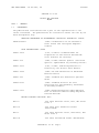
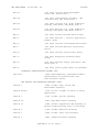


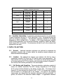


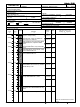

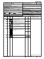
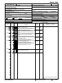


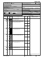

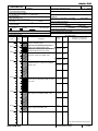
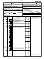

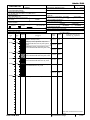


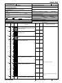


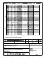


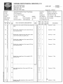


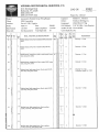


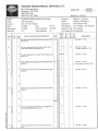
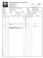


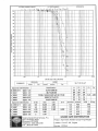
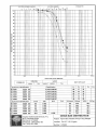


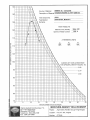
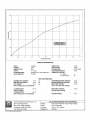


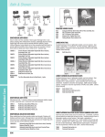

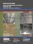
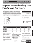
![1127117 - [PROJECT.TOC] - Performance Heating & Plumbing](http://vs1.manualzilla.com/store/data/005895106_1-55e9d6c83dbc31a8ba61d6bb401245cf-150x150.png)