1
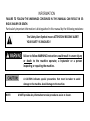
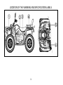
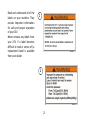
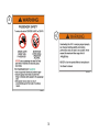
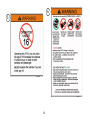
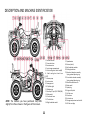
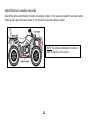
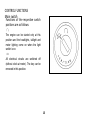
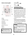
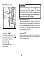
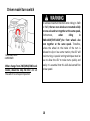
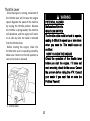
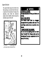
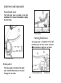
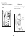
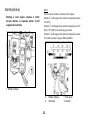
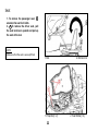
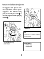
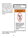
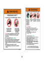
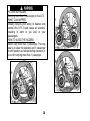
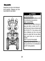
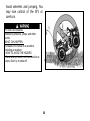
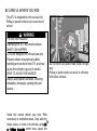
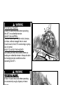
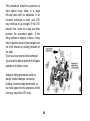
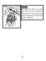
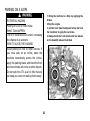
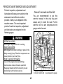
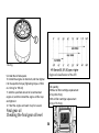
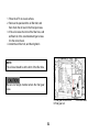
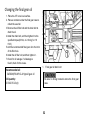
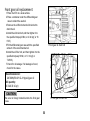
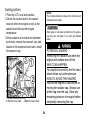
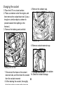
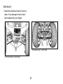
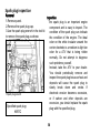
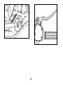
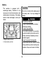
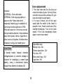
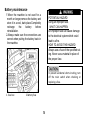
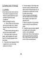
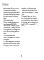
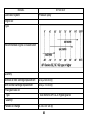
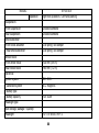
READ THIS MANUAL CAREFULLY! It contains important safety information. 500ATV OWNER’S MANUAL 4×4 This ATV should not be ridden by anyone under 16 years of age. INTRODUCTION Congratulations on your purchase of the 500ATV. With the purchase of this ATV, you can now appreciate the high degree of craftsmanship. This manual will provide you with a good basic understanding of the features and operation of this ATV. This manual includes important safety information. It provides information about special techniques and skills necessary to ride your ATV. It also includes basic maintenance and inspection procedures. If you have any questions regarding the operation or maintenance of your ATV, please consult you dealer. AN IMPORTANT SAFETY MESSAGE: ●READ THIS MANUAL FOR THE ATV RIDER CAREFULLY AND COMPLETELY BEFORE OPERATING YOUR ATV. MAKE SURE YOU UNDERSTAND ALL INSTRUCTIONS. ●PAY CLOSE ATTENTION TO THE WARNING AND CAUTION LABELS ON THE ATV. ●NEVER OPERATE AN ATV WITHOUT PROPER TRAINING OR INSTRUCTION. FREE TRAINING IS AVAILABLE TO ANYONE WHO BUYS A NEW ATV. ●THIS ATV, AND ANY OTHER ATV OVER 90cc, SHOULD NOT BE RIDDEN BY ANYONE UNDER 16 YEARS OF AGE. INFORMATION FAILURE TO FOLLOW THE WARNINGS CONTAINED IN THIS MANUAL CAN RESULT IN SERIOUS INJURY OR DEATH. Particularly important information is distinguished in this manual by the following notations: The Safety Alert Symbol means ATTENTION! BECOME ALERT! YOUR SAFETY IS INVOLVED! Failure to follow WARNING instructions could result in severe injury or death to the machine operator, a bystander or a person inspecting or repairing the machine. A CAUTION indicates special precautions that must be taken to avoid damage to the machine. Avoid damage to the machine. NOTE: A NOTE provides key information to make procedures easier or clearer. IMPORTANT NOTICE This ATV is designed and manufactured for OFF-ROAD use only. It is illegal and unsafe to operate this ATV on any public street, road or highway. This ATV complies with all applicable OFF-ROAD noise level and spark arrester laws and regulations in effect at the time of manufacture. Please check your local riding laws and regulations before operating this ATV. Indicates a potential hazard that could result in serious injury or death. CONTENS LOCATION OF THE WARNING AND SPECIFICATION LABELS.......................................... 1 SAFETY INFORMATION ..................................................................................................................... 5 DESCRIPTION AND MACHINE IDENTIFICATION ..................................................................11 Identification number records .......................................................................................................................12 CONTROL FUNCTIONS......................................................................................................................13 Main switch ...................................................................................................................................................13 Indicator and warning lights ..........................................................................................................................14 Handlebar switches .......................................................................................................................................15 Driver model turn switch ...............................................................................................................................16 Throttle LeverSpeed limiter ...........................................................................................................................17 Speed limiter .................................................................................................................................................18 brake lever and brake pedal ..........................................................................................................................19 Drive select lever ...........................................................................................................................................20 Fuel tank cap .................................................................................................................................................20 Starter(choke) ...............................................................................................................................................21 Seat ...............................................................................................................................................................22 Front and rear shock absorber adjustment ....................................................................................................23 RIDING YOUR ATV ..............................................................................................................................24 GETTING TO KNOW YOUR ATV ......................................................................................................................25 RIDE WITH CARE AND GOOD JUDGEMENT ....................................................................................................25 During operation ..........................................................................................................................................29 BE CAREFUL WHERE YOU RIDE ......................................................................................................................32 TURNING YOUR ATV ......................................................................................................................................35 RIDING DOWNHILL ........................................................................................................................................37 CLIMBING UPHILL ..........................................................................................................................................38 PARKING ON A SLOPE ....................................................................................................................................41 PERIODIC MAINTENANCE AND ADJUSTMENT ...................................................................42 Owner’s manual and tool kit .........................................................................................................................42 PERIODIC MAINTENANCE/LUBRICATION .......................................................................................................43 Engine oil and oil filter cartridge ....................................................................................................................48 To check the engine oil level ..........................................................................................................................48 Changing the final gear oil .............................................................................................................................52 Front gear oil replacement ............................................................................................................................53 Cooling system ..............................................................................................................................................54 Changing the coolant.....................................................................................................................................55 Axle boots .....................................................................................................................................................57 Spark plug inspection ....................................................................................................................................58 Air filter element cleaning .............................................................................................................................60 Valve clearance adjustment ...........................................................................................................................65 Throttle lever adjustment..............................................................................................................................65 Inspecting the brake fluid level ......................................................................................................................67 Cable inspection and lubrication ...................................................................................................................71 Battery ..........................................................................................................................................................73 Replacing a headlight bulb ............................................................................................................................76 Troubleshooting ............................................................................................................................................79 CLEANING AND STORAGE ..............................................................................................................................80 SPECIFICATIONS...................................................................................................................................82 Circuit Diagram, Wiring Diagram and troubleshooting chart ....................................87 LOCATION OF THE WARNING AND SPECIFICATION LABELS 1 Read and understand all of the labels on your machine. They contain important information for safe and proper operation of your ATV. Never remove any labels from your ATV. If a label becomes difficult to read or comes off, a replacement label is available from your dealer. 1 2 2 3 4 3 6 5 4 SAFETY INFORMATION AN ATV IS NOT A TOY AND CAN BE HAZARDOUS TO OPERATE. An ATV handles differently from other vehicles including motorcycles and cars. A collision or rollover can occur quickly, even during routine maneuvers such as turning and riding on hills or over obstacles, if you fail to take proper precautions. SEVERE INJURY OR DEATH can result if you do not follow these instructions: Read this manual and all labels carefully and follow the operating procedures described. Never operate an ATV without proper training or instruction. Take a Training Course. Beginners should receive training from a certified instructor. Contact an authorized ATV dealer. Always follow the age recommendation: A child under 16 years old should never operate an ATV with engine size greater than 90cc. Never allow a child under age 16 to operate an ATV without adult supervision, and never allow continued use of an ATV by a child if he or she does not have the abilities to operate it safely. Never carry more than 1 passenger on an ATV. Always avoid operating an ATV on any paved surfaces, including sidewalks, driveways, parking lots and streets. Never operate an ATV on any public street, road or highway, even dirt or gravel one. Never operate an ATV without wearing an approved motorcycle helmet that fits properly for you and passenger. You should also wear eye protection (goggles or face shield), gloves, boots, a long-sleeved shirt or a jacket, and long pants. Never consume alcohol or drugs before or while operating this ATV. Never operate at speeds too fast for your skills or the conditions. Always go at a speed that is proper for the terrain, visibility, operating conditions, and your experience. 5 Never attempt wheelies, jumps, or other stunts. Always inspect your ATV each time you use it to make sure it is in safe operating condition. Always follow the inspection and maintenance procedures and schedules described in this manual. Always keep both hands on the handlebars and both feet on the footboards of the ATV during operation. Always go slowly and be extra careful when operating on unfamiliar terrain. Always be alert to changing terrain conditions when operating the ATV. Never operate on excessively rough, slippery or loose terrain until you have learned and practiced the skills necessary to control the ATV on such terrain. Always be especially cautious on these kinds of terrain. Always follow proper procedures for turning as described in this manual. Practice turning at low speeds before attempting to turn at faster speeds. Do not turn at excessive speed. Never operate the ATV on hills too steep for the ATV or for your abilities. Practice on smaller hills before attempting larger hills. Always follow proper procedures for climbing hills as described in this manual. Check the terrain carefully before you start up any hill. Never climb hills with excessively slippery or loose surfaces. Shift your weight forward. Never open the throttle suddenly. Never go over the top of a hill at high speed. Always follow proper procedures for going down hills and for braking on hills as described in this manual. Check the terrain carefully before you start down any hill. Shift your weight backward. Never go down a hill at high speed. Avoid going down a hill at an angle that would cause the vehicle to lean sharply to one side. Go straight down the hill where possible. Always follow proper procedures for crossing the side of a hill as described in this manual. Avoid hills with excessively slippery or loose surfaces. Shift your weight to the uphill side of the ATV. Never attempt to turn the ATV around on any hill until you have mastered the turning technique described in this manual on level ground. Avoid crossing the side of a steep hill if possible. 6 Always use proper procedures if you stall or roll backwards when climbing a hill. Maintain a steady speed when climbing a hill. If you stall or roll backwards, follow the special procedure for braking described in this manual. Dismount on the uphill side or to a side if pointed straight uphill. Turn the ATV around and remount, following the procedure described in this manual. Always check for obstacles before operating in a new area. Never attempt to operate over large obstacles, such as large rocks or fallen trees. Always follow proper procedures when operating over obstacles as described in this manual. Always be careful when skidding or sliding. Learn to safely control skidding or sliding by practicing at low 7s and on level, smooth terrain. On extremely slippery surfaces, such as ice, go slowly and be very cautious in order to reduce the chance of skidding or sliding out of control. Never operate an ATV in fast flowing water or in water deeper than that recommended in this manual. Remember that wet brakes may have reduced stopping ability. Test your brakes after leaving water. If necessary, apply those several times to let friction dry out the linings. Always be sure there are no obstacles or people behind you when you operate in reverse. When it is safe to proceed in reverse, go slowly. Always use the size and type of tires specified in this manual. Always maintain proper tire pressure as described in this manual. Never modify an ATV through improper installation or use of accessories. Never exceed the stated load capacity for an ATV. Cargo should be properly distributed and securely attached. Reduce speed and follow instructions in this manual for carrying cargo or pulling a trailer. Allow greater distance for braking. FOR MORE INFORMATION ABOUT ATV SAFETY, Please contact with your 7 dealer. 8 Otherwise, fuel may leak out of the carburetor or fuel tank. WHAT CAN HAPPEN Gasoline is poisonous and can cause injuries. HOW TO AVOID THE HAZARD If you should swallow some gasoline or inhale a lot of gasoline vapor, or get some gasoline in your eyes, see your doctor immediately. If gasoline spills on your skin, wash with soap and water. If gasoline spills on your clothing, change your clothes. POTENTIAL HAZARD Improper handling of gasoline. WHAT CAN HAPPEN Gasoline can catch fire and you could be burned. HOW TO AVOID THE HAZARD Always turn off the engine when refueling. Do not refuel immediately after the engine has been running and is still very hot. Do not spill gasoline on the engine or exhaust pipe/muffler when refueling. Never refuel while smoking, or in the vicinity of sparks, open flames, or other sources of ignition such as the pilot lights of water heaters and clothes dryers. 9 10 DESCRIPTION AND MACHINE IDENTIFICATION 1. Coolant reservoir 2. Drive select lever 3. Rearview mirror 4. Front storage compartment 5. V-belt cooling duct check hose(IN) 6. V-belt cooling duct check hose (OUT) 7. Vacuum pump 8. Spark arrester 9. Passenger seat 10. Tail/brake light 11. Radiator cap 12. Auxiliary DC jack (12V 120W/10A) 13. Main switch 14. Front brake lever 15. Throttle lever 16. Right handlebar switch NOTE: The machine you have purchased may differ slightly from those shown in the figures of this manual. 11 17. Speedometer 18. Starter (choke) 19. Left handlebar switches 20. Parking brake lever 21. Rear shock absorber assembly Spring preload adjusting ring 22. Front shock absorber assembly Spring preload adjusting ring 23. Rear brake fluid reservoir 24. Brake pedal 25. Spark plug 26. Engine oil dipstick 27. Air filter case 28. V-belt case 29. Fuel tank cap 30. Storage compartment and tool kit 31. Oil filter cartridge Identification number records Record the vehicle identification number and engine number in the spaces provided for assistance when ordering spare parts from your dealer or for reference in case the vehicle is stolen. NOTE: The vehicle identification number is used to identify your machine. 12 CONTROL FUNCTIONS Main switch Functions of the respective switch positions are as follows: : The engine can be started only at this position and the headlights, taillight and meter lighting come on when the light switch is on. : All electrical circuits are switched off (without clock at meter). The key can be removed in this position. 13 Indicator and warning lights 12. 4WD indicator light” ” 13. Position light tell-tale indicator light” ” 14. Clock 15. High beams indicator” ” 16. Accumulating mileage and subtotal mileage. 1. Speed meter 2. Left turn” ” 3. Coolant temperature warning light” ” 4. Low indicator light “L” 5. High indicator light “H” 6. Neutral indicator light “N” Coolant temperature warning light When the coolant temperature reaches a specified level, this light comes on to warn that the coolant temperature is too hot. If the light comes on during operation, stop the engine as soon as it is safe to do so and allow the engine to cool down for about 10 minutes. The electrical circuit of the warning light can be checked according to the following procedures. 1. Set the engine stop switch to “ ” and turn the key to “ON”. 2. Shift the drive select lever into the neutral position. 3. Push the start switch. If the warning light does not come on while the start switch is pushed, please call your dealer check the electrical circuit. 7. Reverse indicator light “R” 8. 4WD-LOCK indicator light “DIFF.LOCK” The engine may overheat if the ATV is overloaded. If this happens, reduce the load to specification. Restart after making sure that the light is out. Continuous use while the light is on may cause damage to the engine. 9. Tachometer 10. Right turn” ” 11. Fuel meter NOTE: When the fuel meter has only one mark, should be refilled as soon as possible! Temporality tank remaining has only about 4L! 14 Handlebar switches Do not use the headlights with the engine turned off for more than twenty minutes. The battery may discharge to the point that the starter motor will not operate properly. If this should happen, remove the battery and recharge it. Engine stop switch” / ” Make sure that the engine stop switch is set to “ ”before starting the engine. The engine stop switch controls ignition and can be used at all times to stop the engine, especially in an emergency. The engine will not start or run when the engine stop switch is set to” ”. 1. Light switch“●/ / ” 2. Warning indicator light switch“ 3. Low beams/High beams turn“ 4. Turning switch“ / ●/ ” 5. Horn switch“ ” 6. Start switch“ ” 7. Engine stop switch“ / ” 8. Starter (choke) ” / ” Start switch“ ” Make sure that you must clutch at Front brake lever or trample Brake pedal before starting motor cranks the engine when this switch is pushed. 15 Driver model turn switch 1.4WD/4WD-Lock 2.4WD/2WD When change from 2WD/4WD/4WD-Lock model, should be stop the ATV, and set the switch to correspond position. To achieve maximum traction while riding in 2WD or 4WD, the two rear wheels are mounted solidly on one axle and turn together at the same speed, Furthermore, when riding in 4WD-LOCK(“DIFF-LOCK”),the front wheels also turn together at the same speed. Therefore, unless the wheel on the inside of the turn is allowed to slip or lose some traction, the ATV will resist turning. A special turning technique must be use to allow the ATV to make turns quickly and easily. It is essential that this skills be learned first at low speed. 16 Throttle Lever Once the engine is running, movement of the throttle lever will increase the engine speed. Regulate the speed of the machine by varying the throttle position. Because the throttle is spring-loaded, the machine will decelerate, and the engine will return to an idle any time the hand is removed from the throttle lever. Before starting the engine, check the throttle to be sure it is operating smoothly. Make sure it returns to the idle position as soon as the lever is released. POTENTIAL HAZARD Malfunction of throttle. WHAT CAN HAPPEN The throttle cable could be hard to operate, making it difficult to speed up or slow down when you need to. This could cause an accident. HOW TO AVOID THE HAZARD Check the operation of the throttle lever before you start the engine. If it does not work smoothly, check for the cause. Correct the problem before riding the ATV. Consult your dealer if you can’t find or solve the Problem Yourself. 1. Throttle lever 17 Speed limiter The speed limiter keeps the throttle from fully opening, even when the throttle lever is pushed to the maximum. Turning in the adjusting screw limits the maximum engine power available and decreases the maximum speed of the ATV. 1. Locknut 2.Adjusting screw 3. No more than 12mm(0.47in) POTENTIAL HAZARD Improper adjustment of the speed limiter and throttle. WHAT CAN HAPPEN The throttle cable could be damaged. Improper throttle operation could result. You could lose control, have an accident or be injured. HOW TO AVOID THE HAZARD Do not turn the adjusting screw out more than 18 mm(0.70 in). Always make sure the throttle lever free play is adjusted to 3.0–5.0 mm (0.12–0.20 in). 1. Locknut 2. Adjusting screw a. No more than 18 mm(0.70 in) 18 brake lever and brake pedal Front brake lever The front brake lever is located on the right handlebar. Pull it toward the handlebar to apply the front brake. 1. Brake pedal Parking brake lever The brake lever is located on the left handlebar, pull the lever toward and push ②,the handlebar to apply the rear brake. 1. Front brake lever Brake pedal The brake pedal is located on the right side of the ATV, Push down on the pedal To apply the rear brake. 1. Parking brake lever 19 2.Lockup bar Drive select lever Fuel tank cap The drive select lever is used to shift your machine into the forward, neutral and reverse. Remove the fuel tank cap by Insert key and turning it counterclockwise. 1. Drive select lever 1 .Fuel tank cap 20 Starter(choke) Starting a cold engine requires a richer air-fuel mixture. A separate starter circuit supplies this mixture. NOTE: Use the starter (choke) in reference to the figure: Position①: Cold engine start ambient temperature below 5°C (40°F). Position②: Cold engine start ambient temperature at 0°C (30°F) ~30°C (90°F) and warming up position. Position③: Cold engine start-ambient temperature above 25°C (80°F) and warm engine start position. 1. Starter (choke) a. 2. 21 Starter (choke) Half open 1. Fully open 3. Closed Seat 1. To remove the passenger seat, ○ a unscrew the seat lock bolts. 2. ○ b To remove the driver seat, pull the seat lock lever upward and pull up the seat at the rear. NOTE: Make sure that the seat is securely fitted. 1. Bolt 1.Projection(×2) 22 2. Bolt and nut 2. Seat holder(×2) Front and rear shock absorber adjustment The spring preload can be adjusted to suit the rider’s weight and riding conditions. Adjust the spring preload as follows. To increase the spring preload, turn the adjusting ring in direction ○ a . To decrease the spring preload, turn the adjusting ring in direction ○ b . 1. Special wrench NOTE: A special wrench can be obtained at your dealer to make this adjustment. 1. Spring preload adjusting ring 2. Position indicator Standard position: 2 1- Minimum (soft) 5- Maximum (hard) 23 RIDING YOUR ATV Riding Your ATV 24 Indicates a potential hazard that could result in serious injury or death. GETTING TO KNOW YOUR ATV This ATV is for recreation and utility use. This section, riding your ATV, provides general ATV riding instructions for recreational riding. The skills and techniques described in this section, however, are appropriate for all types of riding. Riding your ATV requires special skills acquired through practice over a period of time. Take the time to learn the basic techniques well before attempting more difficult maneuvers. Riding your new ATV can be a very enjoyable activity, providing you with hours of pleasure. But it is essential to familiarize yourself with the operation of the ATV to achieve the skill necessary to enjoy riding safely. Before you begin to ride, be sure you have read this Owner’s Manual completely and understand the operation of the controls. Please also read all caution and warning labels on you ATV. RIDE WITH CARE AND GOOD JUDGEMENT 25 Get training if you are inexperienced. Beginners should get training from a certified instructor. Become familiar with this ATV at slow speeds first, even if you are an experienced operator. Do not attempt to operate at maximum performance until you are totally familiar with the ATV’s handling and performance characteristics. Not recommended for children under 16 years of age. This ATV is designed to carry operator and cargo and 1 passenger. 26 27 POTENTIAL HAZARD Carrying more than 1 passenger on this ATV. WHAT CAN HAPPEN Greatly reduces your ability to balance and control this ATV. Could cause an accident, resulting in harm to you and/ or your passengers. HOW TO AVOID THE HAZARD Never carry more than 1 passenger. The long seat is to allow the operator and 1 passenger to shift position as needed during operation. It is not for carrying more than 1 passenger. 28 During operation Always keep your feet on the footboards during operation. Otherwise your feet may contact the rear wheels. POTENTIAL HAZARD Removing hands from handlebars or feet from footboards during operation. WHAT CAN HAPPEN Removing even one hand or foot can reduce your ability to control the ATV or could cause you to lose your balance and fall off of the ATV. If you remove a foot from a footboard, your foot or leg may come into contact with the rear wheels, which could injure you or cause an accident. HOW TO AVOID THE HAZARD Always keep both hands on the handlebars and both feet on the footboards of your ATV during operation. 29 Avoid wheelies and jumping. You may lose control of the ATV or overturn. POTENTIAL HAZARD Attempting wheelies, jumps, and other stunts. WHAT CAN HAPPEN Increases the chance of an accident, including an overturn. HOW TO AVOID THE HAZARD Never attempt stunts, such as wheelies or jumps. Don’t try to show off. 30 Modifications POTENTIAL HAZARD Operating this ATV with improper modifications. WHAT CAN HAPPEN Improper installation of accessories or modification of this vehicle may cause changes in handling which in some situations could lead to an accident. HOW TO AVOID THE HAZARD Never modify this ATV through improper installation or use of accessories. All parts and accessories added to this vehicle should be equivalent components designed for use on this ATV and should be installed and used according to instructions. If you have questions, consult an authorized ATV dealer. 31 BE CAREFUL WHERE YOU RIDE This ATV is designed for off-road use only. Riding on paved surfaces can cause loss of control. POTENTIAL HAZARD Operating this ATV on paved surfaces. WHAT CAN HAPPEN ATVs are designed for off-road use only. Paved surfaces may seriously affect handling and control of the ATV, and may cause the vehicle to go out of control. HOW TO AVOID THE HAZARD Always avoid paved surfaces, including sidewalks, driveways, parking lots and streets. Know the terrain where you ride. Ride cautiously in unfamiliar areas. Stay alert for holes, rocks, or roots in the terrain, and oth-32 Do not ride on any public road, street, or highway. Riding on public roads can result in collisions With other vehicles. POTENTIAL HAZARD Failure to use extra care when operating this ATV on unfamiliar terrain. WHAT CAN HAPPEN You can come upon hidden rocks, bumps, or holes, without enough time to react. Could result in the ATV overturning or going out of control. HOW TO AVOID THE HAZARD Go slowly and be extra careful when operating on unfamiliar terrain. Always be alert to changing terrain conditions when operating the ATV. POTENTIAL HAZARD Failure to use extra care when operating on excessively rough, slippery or loose 33 34 TURNING YOUR ATV To achieve maximum traction while riding off-road, the two rear wheels are mounted solidly on one axle and turn together at the same speed. Therefore, unless the wheel on the inside of the turn is allowed to slip or lose some traction, the ATV will resist turning. A special turning technique must be used to allow the ATV to make turns quickly and easily. It is essential that this skill be learned first at low speed. As you approach a curve, slow down and begin to turn the handlebars in the desired direction. As you do so, put your weight on the footboard to the outside of the turn (opposite your desired direction) and lean your upper body into the turn. Use the throttle to maintain an even speed through the turn. This maneuver will let the wheel on the inside of the turn slip slightly, allowing the ATV to make the turn properly. POTENTIAL HAZARD Turning improperly. WHAT CAN HAPPEN ATV could go out of control, causing a collision or overturn. HOW TO AVOID THE HAZARD Always follow proper procedures for turning as described in this Owner’s Manual. Practice turning at low speeds before attempting to turn at faster speeds. Do not turn at speeds too fast for your skills or the conditions. If the ATV begins to tip over to the outside while negotiating a turn, lean more to the 35 in-side. It may also be necessary to This procedure should be practiced at slow speed many times in a large off-road area with no obstacles. If an incorrect technique is used, your ATV may continue to go straight. If the ATV doesn’t turn, come to a stop and then practice the procedure again. If the riding surface is slippery or loose, it may help to position more of your weight over the front wheels by moving forward on the seat. Once you have learned this technique you should be able to perform it at higher speeds or in tighter curves. Improper riding procedures such as abrupt throttle changes, excessive braking, incorrect body movements, or too much speed for the sharpness of the turn may cause the ATV to tip. 36 RIDING DOWNHILL When riding your ATV downhill, shift your weight as far to the rear and uphill side of the ATV as possible. Move back on the seat and sit with your arms straight. Engine compression will do most of the braking for you. For maximum engine compression braking effect, change to 4WD before beginning to descend the hill. Improper braking may cause a loss of traction. Use caution while descending a hill with loose or slippery surfaces. Braking ability and traction may be adversely affected by these surfaces. Improper braking may also cause a loss of traction. When this ATV is in 4WD, all wheels (front and rear) are interconnected by the drive train. This means that applying either the front brake or the rear brake will brake all wheels. When descending hills, using either brake lever or the brake pedal will brake the wheels on the downhill side. Avoid sudden application of either the front or rear brake because the wheels on the uphill side could come off the ground. Apply both the front and rear brakes gradually. Whenever possible, ride your ATV straight downhill. Avoid sharp angles which could allow the ATV to tip or roll over. Carefully choose your path and ride no faster than you will be able to react to obstacles which may appear. 37 CLIMBING UPHILL Never go over the top of any hill at high speed. An obstacle, a sharp drop, or another vehicle or person could be on the other side of the hill. POTENTIAL HAZARD Climbing hills improperly. WHAT CAN HAPPEN Could cause loss of control or cause the ATV to overturn. HOW TO AVOID THE HAZARD Always follow proper procedures for climbing hills as described in this Owner’s Manual. Always check the terrain carefully before you start up any hill. Never climb hills with excessively slippery or loose surfaces. Shift your weight forward. Never open the throttle suddenly. The ATV could flip over backwards. Never operate the ATV on hills steeper than 25°. 38 CROSSING THROUGH SHALLOW WATER The ATV can be used to cross slow POTENTIAL HAZARD moving, shallow water of up to a maximum recommended depth equal to the bottom of the footrests. Follow these procedures when operating through water. 1. Determine water depths and current before crossing. 2. Choose a crossing where both banks and obstacles if possible. 3. Proceed slowly, avoiding rocks and obstacles if possible. Operating this ATV through deep or fast flowing water. WHAT CAN HAPPEN Tires may float, causing loss of traction and loss of control, which could lead to an accident. HOW TO AVOID THE HAZARD Never operate this ATV in fast flowing water or in water deeper than that specified in your Owner’s Manual. Remember that wet brakes may have reduced stopping ability. Test your brakes after leaving water. If necessary, apply them several times to let friction dry out the linings. 4. Test your brakes after leaving the water, Do not continue to ride your ATV without verifying that you have regained proper braking ability. 39 After riding your ATV in water, be sure to check the trapped water at the air filter, V-belt cooling duct, the storage compartment. If necessary, drain any water that may have accumulated. Also, if it has been operated in salt water or muddy conditions. 40 PARKING ON A SLOPE 1. Bring the machine to a Stop by applying the brakes. 2.Stop the engine. 3. pull the lever toward and push lockup bar lock the handlebar to apply the rear brake. 4. Always block the front wheels and rear wheels on the downhill side as illustrated. POTENTIAL HAZARD Parking on a hill or other incline. WHAT CAN HAPPEN The ATV could roll out of control, increasing the chance of an accident. HOW TO AVOID THE HAZARD Avoid parking on hills or other inclines. If you must park on an incline, place the machine transversely across the incline, apply the parking brake, and block the front and rear wheels with rocks or other objects. Do not park the ATV at all on hills that are so steep you could not walk up them easily. 41 PERIODIC MAINTENANCE AND ADJUSTMENT Periodic inspection, adjustment and lubrication will keep your machine in the safest and most efficient condition possible. Safety is an obligation of the machine owner. The most important points of machine inspection, adjustment and lubrication are explained on the following pages. Owner’s manual and tool kit You are recommended to put this owner’s manual in the vinyl bag and always carry it under the seat. Put the owner’s tool kit and low-pressure tire gauge under the seat. POTENTIAL HAZARD Servicing an engine while it is running. WHAT CAN HAPPEN Moving parts can catch clothing or parts of the body, causing injury. Electrical components can cause shocks or can start fires. HOW TO AVOID THE HAZARD Turn off the engine when performing maintenance unless otherwise specified. Have your dealer perform service if you are not familiar with machine service. 1. Owner’s manual 2.Owner’s tool kit and Low-pressure tire gauge 42 PERIODIC MAINTENANCE/LUBRICATION NOTE: ●For ATVs not equipped with an odometer or an hour meter, follow the month maintenance intervals. ●For ATVs equipped with an odometer or an hour meter, follow the km (mi) or hours maintenance intervals. How-ever, keep in mind that if the ATV isn’t used for a long period of time, the month maintenance intervals should be followed. ITEM Valves* Cooling system Spark plug Air filter element Carburetor* ROUTINE • • • • • • • • • • • • Whichever comes first month km (mi) hours Check valve clearance. Adjust if necessary. Check coolant leakage. Repair if necessary. Replace coolant every 24 months. Check condition. Adjust gap and clean. Replace if necessary. Clean. Replace if necessary. Check starter (choke). Adjust engine idling speed. 43 1 250 (155) 20 INITIAL 3 6 500 1000 (310) (620) 75 150 ● EVERY 6 12 2000 3000 (1240) (1860) 150 300 ● ● ● ● ● ● ● ● ● ● ● ● ● Every 20-40 hours (More often in wet or dusty areas) ● ● ● ● ITEM Crankcase breather system* Exhaust system* Spark arrester Fuel line* Engine oil Engine oil filter cartridge Engine oil strainer* Final gear oil Differential gear oil Front brake* Rear brake* month ROUTINE km (mi) hours • Check breather hose for cracks or damage. • Replace if necessary. • Check for leakage. • Tighten if necessary. • Replace gasket(s) if necessary. • Clean. • Check fuel hose for cracks or damage. • Replace if necessary. • Replace. (Warm engine before draining.) Whichever comes first 1 250 (155) 20 INITIAL 3 6 500 1000 (310) (620) 75 150 EVERY 6 12 2000 3000 (1240) (1860) 150 300 ● ● ● ● ● ● ● ● ● ● ● ● ● ● ● ● • Replace. ● ● ● • • • • • • • ● ● ● Clean. Check for oil leakage. Replace every 12 months. Check operation/fluid leakage. Correct if necessary. Check operation/fluid leakage. Adjust if necessary. ● 44 ● ● ● ● ● ● ● ● ● ● ● ITEM Select lever safety system cable* V-belt* Wheels* Wheel bearing* Front and rear suspension* Steering system* Rear upper and lower knuckle pivots* Drive shaft universal joint* ROUTINE Whichever comes first • Check operation. month km (mi) hours 1 250 (155) 20 INITIAL 3 6 500 1000 (310) (620) 75 150 ● ● ● ● ● ● ● ● ● ● ● ● ● ● ● • Adjust if necessary. • Check operation. • Check for cracks or damage. • Check balance/damage/runout. • Repair if necessary. • Check bearing assemblies for looseness/damage. • Replace if damaged. • Check operation. • Correct if necessary. • Check operation./Replace if damaged. • Check toe-in./Adjust if necessary. EVERY 6 12 2000 3000 (1240) (1860) 150 300 ● ● ● ● • Lubricate with lithium-soap-based grease. ● ● ● • Lubricate with lithium-soap-based grease. ● ● ● 45 ● ● ● ITEM Engine mount* Front and rear axle boots* Stabilizer bushes* Fittings and fasteners* Lights and switches* ROUTINE Whichever comes first month km (mi) hours • Check for cracks or damage. • Check operation. • Replace if damaged. 1 250 (155) 20 ● • Check for cracks or damage. • Check all chassis fittings and fasteners. • Correct if necessary. • Check operation. • Adjust headlight beams. INITIAL 3 6 500 1000 (310) (620) 75 150 ● ● EVERY 6 12 2000 3000 (1240) (1860) 150 300 ● ● ● ● ● ● ● ● ● ● ● ● ● ● ● ● ● ● * Since these items require special tools, data and technical skills, have your dealer perform the service. 46 NOTE: ●Recommended brake fluid: DOT 3 or DOT 4 ●Brake fluid replacement: ●When disassembling the master cylinder or caliper, replace the brake fluid. Normally check the brake fluid level and add fluid as required. ●On the inner parts of the master cylinder and caliper, replace the oil seals every two years. ● Replace the brake hoses every four years, or if Indicates a potential hazard that could cracked or damaged. Indicates a potential hazard that could result in serious injury or death. 47 Engine oil and oil filter cartridge The engine oil level should be checked before each ride. In addition, the oil must be changed and the oil filter cartridge replaced at the intervals specified in the periodic maintenance and lubrication chart. Check the engine oil level 1. Remove the bolt and panel. 2. Place the ATV on a level surface . 3. Start the engine ,warm it up for several minutes, and then turn it off. 4. Wait a few minutes until the oil settles. 5. Remove the engine oil filler cap and wipe off the dipstick with a clean rag. 6. Insert the dipstick in the oil filler hole (screwing it in), and then remove it again to check the oil level. 7. If the engine oil is at or below the minimum level mark , add sufficient oil of the recommended type to raise it to the correct level. 8. Insert the dipstick into the oil filler hole, and then tighten the oil filler cap. 9. Install the panel and bolt. Change the engine oil (with or without and then tighten the oil filler cap. oil filter cartridge replacement) 1.Bolt 2.Panel 1. Maximum level mark 2.Minimum level mark NOTE: The engine oil should be between the minimum and maximum lever marks. NOTE: Skip steps 5–9 if the oil filter cartridge is not 48 being replaced. 1. Remove bolt and panel. 2. Start the engine, warm it up for several minutes, and then turn it off. 3. Place an oil pan under the engine to collect the used oil, and then remove the engine oil filler cap. 4.Remove the engine oil drain bolt to drain the oil from the crankcase. 5. Remove left side panel. 6. Remove the oil filter cartridge with an oil filter wrench. 7. Apply a light coat of engine oil to the O-ring of the new oil filter cartridge. 8. Install the new oil filter cartridge(Tightening torque:17Nm or 1.7m.kgf or 12 ft.ibf). 1. Engine oil drain bolt NOTE: Make sure the O-ring is seated properly. 1. Engine oil filter cartridge minutes. While warming up, check for oil leakage. If oil leakage is found, turn the engine off immediately and check for the cause. 4913.Turn the engine off, and then check the oil level and correct it if necessary. 1.O-ring 9. Install the left side panel. 10. Install the engine oil drain bolt ,and then tighten it to the specified torque(Tightening torque :23Nm or 2.3m.kgf or 16ft.ibf). 11. Add the specified amount of recommended engine oil ,and then install the engine oil filler cap and tighten it. 12. Start the engine and warm it up for several Engine oil classification of the ATV Oil quantity: Without oil filter cartridge replacement : 2.5L(2.64 US qt) With oil filter cartridge replacement : 2.6L(2.75 US qt) Final gear oil Checking the final gear oil level 50 1. Place the ATV on a level surface. 2. Remove the panel and the oil filler bolt, and then check the oil level in the final gear case. 3. If the oil is below the brim of the filler hole, add sufficient oil of the recommended type to raise it to the correct level. 4. Install the oil filler bolt, and then tighten it. NOTE: The oil level should be at the brim of the filler hole. Be sure no foreign material enters the final gear case. 1.Final gear oil filler bolt 3.Final gear oil 51 2.Correct level Changing the final gear oil 1. Place the ATV on a level surface. 2. Place a container under the final gear case to collect the used oil. 3.Remove the oil filler bolt and the drain bolt to drain the oil. 4.Install the drain bolt ,and then tighten it to the specified torque(23 Nm, or 2.3m·kgf, or 16 ft·ibf ) 5.Add the recommended final gear oil to the brim of the filler hole. 6.Install the oil filler bolt ,and then tighten it . 7.Check for oil leakage .if oil leakage is found ,check for the cause. Recommended oil: SAE 80W/90 API GL-4 Hypoid gear oil Oil quantity: 0.33L0.35 US qt) 1. Final gear oil drain bolt Be sure no foreign material enters the final gear case. 52 Front gear oil replacement 1.Place the ATV on a level surface. 2.Place a container under the differential gear case to collect the used oil. 3.Remove the oil filler bolt and oil drain bolt to drain the oil. 4.Install the oil drain bolt ,and then tighten it to the specified torque(23 Nm, or 2.3m·kgf, or 16 ft·ibf ) 5.Fill the differential gear case with the specified amount of the recommended oil. 6.Install the oil filler bolt, and then tighten it to the specified torques(10 Nm, or 1.0 m·kgf, or 7.2ft·Ibf). 7.Check for oil leakage. If oil leakage is found, check for the cause. 1.Front gear oil drain bolt Recommended oil: SAE 80W/90 API GL-4 Hypoid gear oil Oil quantity: 0.33L0.35 US qt) Be sure no foreign material enters the final gear case. 1.Front gear oil filler bolt 53 Cooling system NOTE: The coolant should be between the minimum and maximum level marks. 1.Place the ATV on a level surface. 2.Check the coolant level in the coolant reservoir when the engine is cold as the coolant level will vary with engine temperature. 3.If the coolant is at or below the minimum level mark, remove the reservoir cap, add coolant to the maximum level mark, install the reservoir cap. Hard water or salt water is harmful to the engine. you may use soft water if you can’t get distilled water. POTENTIAL HAZARD Removing the radiator cap when the engine and radiator are still hot. WHAT CAN HAPPEN You could be burned by hot fluid and steam blown out under pressure. HOW TO AVOID THE HAZARD Wait for the engine to cool before removing the radiator cap. Always use a thick rag over the cap. Allow any remaining pressure to escape before completely removing the cap. 1.Coollant reservoir and cap 2.Miximum level mark 3.Maximum level mark 54 Changing the coolant 1.Place the ATV on a level surface. 2. Place a container under the engine, and then remove the coolant drain bolt. (Use a trough or a similar object as shown to prevent coolant from spilling on the footrest.) 3. Remove the battery panel and bolt. 4.Remove the radiator cap. 1.Radiator cap 6.Remove coolant reservoir cap. 1.Battery panel and bolt until it reaches thehose top of the radiator. 7. Disconnect the hose on the coolant 1.Coolant reservoir 14.Check for coolant leakage. reservoir side, and then drain the coolant from the coolant reservoir. 55 8. After draining the coolant, thoroughly Hard water or salt water is harmful to the engine. you may use soft water if you can’t get distilled water. 56 Axle boots Check the protective boots for holes or tears. If any damage is found, have them replaced by your dealer. 1.Rear axle boot(×2 each side) 1.Front axle boot(×2 each side) 57 Spark plug inspection Removal Inspection 1.Remove panel. The spark plug is an important engine 2.Remove the spark plug cap. component and is easy to inspect. The 3.Use the spark plug wrench in the tool kit condition of the spark plug can indicate to remove the spark plug as shown. the condition of the engine. The ideal color on the white insulator around the center electrode is a medium-to-light tan color for a ATV that is being ridden normally. Do not attempt to diagnose such problems yourself. Instead, take the ATV to your dealer. You should periodically remove and inspect the spark plug because heat and deposits will cause the spark plug to slowly break down and erode. If electrode erosion becomes excessive, 1.Spark plug wrench or if carbon and other deposits are excessive, you should replace the spark Specified spark plug: plug with the specified plug. K6RTC 58 Installation 1.Measure the electrode gap with a wire thickness gauge and, if necessary, adjust the gap to specification. 2.Clean the gasket surface. Wipe off any grime from the threads. 3.Install the spark plug and tighten it to the specified torque:17.5 Nm (1.75 m·kgf, 12.5 ft·lbf) 4. Install the spark plug cap. 5. Install the panel. a. Spark plug gap 59 Spark plug gap: 0.6~0.7mm(0.024~0.028 in) NOTE: If a torque wrench is not available when you are installing a spark plug, a good estimate of the correct torque is 1/4 to 1/2 turn past finger tight. Have the spark plug tightened to the specified torque as soon as possible. Air filter element cleaning NOTE: There is a check the air filter case. If dust collects 4.Remove these bolts, and remove the air filter frame. in the air filter, clean the air filter element and air filter case, If have water in the air filter, exchange the air filter element.. 1.Remove passenger seat and driver seat. 2.Remove the right panel. 3.Remove the clip bolt. 1.Bolts 2.Air filter frame 5.Pull off the lock plate, remove the air filter case cover. 6.Take out the air filter element. 7. Inspect the air filter element and replace it if damaged. 1. clip bolt 60 1.Compressed air gun 2.Filter element 1.Air filter case cover 7.Use the compressed air gun blow the filter element according to the photo, if you have not compressed air gun, you should be tap it lightly until it cleanly. 8. Install the air filter element assembly. 9. Install the air filter case cover by hooking the lock plate onto the air filter case. 10. Install the air filter clip bolt and the air filter frame. 11. Install the right panel. 12. Install passenger seat and driver seat. NOTE: The air filter element should be cleaned every 61 POTENTIAL HAZARD Using solvents or gasoline to clean the Never operate the engine with the air filter element removed. This will allow unfiltered air to enter, causing rapid engine wear and possible engine damage. Additionally, operation without the air filter element will affect carburetor jetting with subsequent poor performance and possible engine overheating. 62 Carburetor adjustment Idle speed adjustment The carburetor is a vital part of the engine and requires very sophisticated adjustment. Most adjusting should be left to your dealer who has the professional knowledge and experience to do so. However, the idling speed may be performed by the owner as a part of the usual maintenance routine. NOTE: A diagnostic tachometer must be used for this procedure. 1.Start the engine and warm it up for a few minutes at approximately 1,000 to 2,000 r/min. Occasionally rev the engine to 4,000 to 5,000 r/min. The engine is warm when it quickly responds to the throttle. 2.Remove the seat. 3.Then set the idle to the specified idling speed by adjusting the throttle stop screw. Turn the screw in direction a to increase the engine speed, and in direction b to decrease the engine speed. 4.Install the seat. NOTE: Adjust the engine idling speed before check the throttle lever free play. Specified idle speed: 3.0~5.0 mm(0.12~0.20 in) Specified idle speed: 1500±150 r/min 63 The carburetor was set at the factory after many tests. If the settings are disturbed by someone without sufficient technical knowledge, poor engine performance and damage may result. 64 Valve clearance adjustment The correct valve clearance changes with use, resulting in improper fuel/air supply or engine noise. To prevent this, the valve clearance must be adjusted regularly. This adjustment however, should be left to a professional service technician. Throttle lever adjustment NOTE: Adjust the engine idling speed before check the throttle lever free play. Specified idle speed: 3.0~5.0 mm(0.12~0.20 in) 1. Adjusting bolt a. Throttle lever free play 1.Loosen the locknut. 2.Turn the adjusting bolt until the throttle lever free play to the Specified valve clearance. 3.Tighten the locknut. 65 2. Locknut Front brake pad check Rear brake pad check Check the brake pads for damage and wear. If a brake pad thickness is less than 1.0 mm (0.04 in), have your dealer replace the pads as a set. Check the brake pads for damage and wear. If a brake pad thickness is less than 2 mm (0.08 in), have your dealer replace the pads as a set. a. Brake pad thickness a. Brake pad thickness NOTE: The wheels need to be removed to check the brake pads. 66 Inspecting the brake fluid level Insufficient brake fluid may let air enter the brake system, possibly causing the brakes to become ineffective. Before riding, check that the brake fluid is above the minimum level mark and replenish when necessary. A low brake fluid level may indicate worn brake pads and/or brake system leakage. If the brake fluid level is low, be sure to check the brake pads for wear and the brake system for leakage. 1. Minimum level mark Observe these precautions: When checking the fluid level, make sure the top of the master cylinder reservoirs are level. Use only the designated quality brake fluid. Otherwise, the rubber seals may deteriorate, causing leakage and poor brake performance. 1. Minimum level mark Recommended brake fluid: DOT3 or DOT 4 67 c d Refill with the same type of brake fluid. Mixing fluids may result in a harmful chemical reaction and lead to poor brake performance. Be careful that water does not enter the master cylinder reservoirs when refilling. Water will significantly lower the boiling point of the fluid and may result in vapor lock. Brake fluid may deteriorate painted surfaces or plastic parts. Always clean up spilled fluid immediately. Have your dealer check the cause if the brake fluid level goes down. Brake fluid replacement Complete fluid replacement should be done only by trained service personnel. Have your dealer replace the following components during periodic maintenance or when they are damaged or leaking. Replace the oil seals every two years. Replace the brake hoses every four years. Front brake lever free play The front brake lever should have a free play of zero mm (zero in) at the lever end. If not, have your dealer check the brake system. a. Front brake lever free play 68 Adjusting the parking brake lever and brake pedal Adjusting the parking brake lever POTENTIAL HAZARD Operating with improperly serviced or adjusted brakes. WHAT CAN HAPPEN You could lose braking ability, which could lead to an accident. HOW TO AVOID THE HAZARD After servicing: Make sure the brakes operate smoothly and that the free play is correct. Make sure the brakes do not drag. Make sure the brakes are not spongy. All air must be bled from the brake system. Replacement of brake components requires professional knowledge. These procedures should be performed by your dealer. The parking brake lever free play should be 5~7 mm (0.19~0.27 in). 1. Loosen the locknut. 2. Turn the adjusting bolt in direction a to increase free play, and in direction b to decrease free play. 3. Tighten the locknut. 1. Adjusting bolt 2.Locknut 3. Lockup bar C. Parking brake lever free play If correct free play cannot be obtained, ask your dealer to make that adjustment. 69 POTENTIAL HAZARD NOTE: When adjusting the rear brake lever free play: Be sure not to step on the brake pedal. Make sure the brake pedal does not move. Adjusting the brake pedal The top of the brake pedal should be positioned 72 mm (2.83 in) above the top of the footrest. If not, ask your dealer to adjust it. a. Brake pedal position 70 Cable inspection and lubrication Lubricating the brake lever and brake pedal and parking lever POTENTIAL HAZARD Damaged control cables. WHAT CAN HAPPEN Corrosion can result when the outer covering of control cables becomes damaged. Cables can also become frayed or kinked. Operation of controls could be restricted, which could cause an accident or injury. HOW TO AVOID THE HAZARD Inspect cables frequently. Replace damaged cables. Lubricate the pivoting parts. Recommended lubricant : Lithium-soap-based grease (all-purpose grease) Lubricate the inner cables and the cable ends. If the cables do not operate smoothly, ask your dealer to replace them. Recommended lubricant: SAE 10W30 motor oil 71 72 Battery This machine is equipped with a sealed-type battery. Therefore it is not necessary to check the electrolyte or add distilled water in the battery. If the battery seems to have discharged, consult your dealer. Do not try to remove the sealing caps of the battery cells. You may damage the battery. POTENTIAL HAZARD Failure to handle batteries or battery electrolyte carefully. WHAT CAN HAPPEN You could be poisoned. You could be severely burned by the sulfuric acid in battery electrolyte. Batteries produce explosive gases. HOW TO AVOID THE HAZARD Avoid contact with skin, eyes or clothing. Always shield eyes when working near batteries. Keep out of reach of children. 1. Negative battery terminal 2. Positive battery terminal 73 Fuse replacement 1. The main fuse and the fan fuse are under the battery panel, the front driver controller fuse and the auxiliary DC jack fuse are inside the right panel. 2. If a fuse is blown, turn off the main switch and the switch of the circuit in question. then, install a new fuse of the specified amperage. Turn on the main switch. If the fuse immediately blows again, consult your dealer. Antidote: EXTERNAL: Flush with water. INTERNAL: Drink large quantities of water or milk. Follow with milk of magnesia, beaten egg or vegetable oil. Get prompt medical attention. EYES: Flush with water for 15 minutes and get prompt medical attention. Keep batteries away from sparks, flames, cigarettes or other sources of ignition. Ventilate when charging or using in a closed space. Specified fuses: Battery fuse: 30A Power output fuse: 10A Fan fuse: 10A Main switch fuse: 10A Light fuse: 20A A special battery charger (constant voltage/ampere or constant voltage) is required for recharging a sealed type battery. using a conventional battery charger may shorten the battery life. 74 Battery maintenance 1.When the machine is not used for a month or longer,remove the battery and store it in a cool, dark place.Completely recharge the battery before reinstallation. 2.Always make sure the connections are correct when putting the battery back in the machine. POTENTIAL HAZARD Using an improper fuse. WHAT CAN HAPPEN An improper fuse can cause damage to the electrical system which could lead to a fire. HOW TO AVOID THE HAZARD Always use a fuse of the specified rating. Never use a material in place of the proper fuse. To prevent accidental short-circuiting, turn off the main switch when checking or replacing a fuse. 1. fuse box 2.Battery fuse 75 Replacing a headlight bulb If a headlight bulb burns out, replace it as follows. 1. Remove the bolts and the fender. 2. Remove the headlight panel. 3. Remove the bulb holder cover at the rear of the headlight by pulling it off. 4. Remove the headlight bulb holder by turning it counterclockwise. 5. Remove the defective bulb by unhooking the headlight bulb holder tabs. 6. Insert a new headlight bulb into the bulb holder, and then secure the bulb by hooking the tabs onto the bulb. 7. Install the headlight bulb holder by turning it clockwise. 8. Install the headlight bulb holder cover at the rear of the headlight. 9. Install the headlight panel. 10. Install the bolts and the fender. 1. Headlight panel 1. Bolts 2. Fender 76 2.bolts 1. Headlight bulb holder Do not touch the glass part of the headlight bulb to keep it free from oil, otherwise the transparency of the glass, the luminosity of the bulb, and the bulb life will be adversely affected. Thoroughly clean off any dirt and fingerprints on the headlight bulb using a cloth moistened with alcohol or thinner. 77 Headlight beam adjustment Tail/brake light bulb replacement 1. Remove the tail/brake light bulb holder by turning it counterclockwise. 2. Remove the defective bulb by unhooking the tail/brake light bulb holder tabs. 3. Insert a new tail/brake light bulb into the bulb holder, and install the tail/brake light bulb holder by turning it clockwise. It is advisable to have your dealer make this adjustment. To raise the beam, turn the adjusting screw indirection a. To lower the beam, turn the adjusting screw indirection b. 1. Tail/brake light bulb holder 1. Head beam adjusting screw 78 Troubleshooting Although the machines receive a rigid inspection before shipment from the factory, trouble may occur during operation. Any problem in the fuel, compression, or ignition systems can cause poor starting and loss of power. The troubleshooting chart describes a quick, easy procedure for making checks. If your machine requires any repair, take it to your dealer. The skilled technicians at your dealer dealership have the tools, experience, and know how to properly service your machine. Use only genuine parts on your machine. Imitation parts may look like parts, but they are often inferior. Consequently, they have a shorter service life and can lead to expensive repair bills. POTENTIAL HAZARD Checking the fuel system while smoking or near an open flame. WHAT CAN HAPPEN Fuel can ignite or explode, causing severe injury or property damage. HOW TO AVOID THE HAZARD Do not smoke when checking the fuel system. Make sure there are no open flames or sparks in the area, including pilot lights from water heaters or furnaces. 79 CLEANING AND STORAGE Ⅳ Once the majority of the dirt has been hosed off, wash all surfaces with warm water and mild, detergent-type soap. An old toothbrush or bottle brush is handy for hard-to-get-at places. Ⅴ Rinse the machine off immediately with clean water and dry all surfaces with a chamois, clean towel or soft absorbent cloth. Ⅵ Clean the seat with a vinyl upholstery cleaner to keep the cover pliable and glossy. Ⅶ Automotive type wax may be applied to all painted and chrome plated surfaces. Avoid combination cleaner-waxes. Many contain abrasives which may mar the paint or protective finish. When finished, start the engine and let it idle for several minutes. CLEANING Keep cleaning of your machine will not only enhance its appearance but will improve its general performance and extend the useful life of many components. Ⅰ Before cleaning the machine: a. Block off the end of the exhaust pipe to prevent water entry. A plastic bag and strong rubber band may be used. b. Make sure the spark plug and all filler caps are properly installed. Ⅱ If the engine case is excessively greasy, apply degreaser with a paint brush. Do not apply degreaser to the wheel axles. Ⅲ Rinse the dirt and degreaser off with a garden hose. Use only enough pressure to do the job. 80 STORAGE Long term storage (60 days or more) of your machine will require some preventive procedures to guard against deterioration. After thoroughly cleaning the machine, prepare for storage as follows: 1. Drain the fuel system. 2. Remove the spark plug, pour about one tablespoon of SAE 10W30 or 20W40 motor oil in the spark plug hole and rein-stall the spark plug. Ground the spark plug wire and turn the engine over several times to coat the cylinder wall with oil. 3. Lubricate all control cables. 4. Block up the frame to raise all wheels off the ground. 5. Tie a plastic bag over the exhaust pipe outlet to prevent moisture from entering. 6. If storing in a humid or salt-air cover. atmosphere, coat all exposed metal surfaces with a light film of oil. Do not apply oil to any rubber parts or the seat cover. 7. Remove the battery and charge it. Store it in a dry place and recharge it once a month. Do not store the battery in an excessively warm or cold place (less than 0 °C (30 °F) or more than 30 °C (90 °F)). 81 SPECIFICATIONS MODEL XY500 ATV Dimensions: Overall length 2,085 mm (82.0 in) Overall width 1,180 mm (46.4 in) Overall height 1,175 mm (46.2 in) Seat height 865mm Wheelbase 1,300 mm (51.1 in) Minimum ground clearance 260 mm (10.2 in) 3,500mm (137.7 in) Minimum turning radius (34.0 in) Basic weight: With oil and full fuel tank 355 Kg (782.6lb) Engine: Engine type Cylinder arrangement Liquid-cooled 4-stroke, SOHC Forward-inclined single cylinder Displacement 498.6 CC Bore × stroke 92.0×75.0 mm Compression ratio 10.2:1 Starting system Electric 82 (3.6×2.9 in) MODEL Lubrication system XY500 ATV Pressure spray Engine oil: Type Recommended engine oil classification Quantity: Without oil filter cartridge replacement 2.5L(2.64 US qt) With oil filter cartridge replacement 2.6L(2.75 US qt) Final gear case oil: Type SAE 80W/90 API GL-4 Hypoid gear oil Quantity: Periodic oil change 0.33L0.35 US qt) 83 MODEL XY500 ATV Front gear case oil: Type SAE 80W/90 API GL-4 Hypoid gear oil Quantity: Periodic oil change Air filter: 0.33L0.35 US qt) dry element Fuel: Type UNLEADED GASOLINE ONLY Fuel tank capacity 22.0 L (5.8 Gal) Fuel reserve amount about 4 L (1 Gal) Carburetor: Type/quantity Manufacturer PD34 / 1 KEIHIN Spark plug: Type/manufacturer K6RTC Spark plug gap 0.6–0.7 mm (0.024–0.028 in) Clutch type: Dry, centrifugal automatic Transmission: Primary reduction system V-belt 84 MODEL XY500 ATV Secondary reduction system Shaft drive Transmission type V-belt automatic Operation Left hand operation High gear 2.16:1 Low gear 3.69:1 Reverse gear 2.7:1 Chassis: Frame type Steel tube frame Caster angle 7° Trail Tire: Type Size Tubeless front AT25×8-12 rear AT25×10-12 type Dual disc brake operation Right hand operation type Single disc brake Brake: Front brake Rear brake 85 MODEL XY500 ATV operation right foot operation / Left hand parking Suspension: Front suspension Double wishbone Rear suspension Double wishbone Shock absorber: Front shock absorber Rear shock absorber Coil spring / oil damper Coil spring / oil damper Wheel travel: Front wheel travel 124 mm (4.8 in) Rear wheel travel 183 mm (7.2 in) Electrical: Ignition system Generator system DC. C.D.I. A.C. magneto Battery type Battery capacity 12V 20Ah Headlight type: Bulb voltage, wattage × quantity: Headlight 12 V 35 W/35.0 W × 2 86 MODEL Tail/brake light XY500 ATV 12 V 5 W/21.0 W × 2 Indicator light Neutral indicator light LED × 1 High gear indicator light LED × 1 Low gear indicator light LED × 1 Reverse gear indicator light LED × 1 Coolant temperature warning light LED × 1 4WD-Lock drive indicator light LED × 1 Fuses: Battery fuse 30A Main switch fuse 10A Light fuse 20A Power output fuse 10A Fan fuse 10A 87