1
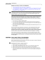
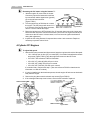
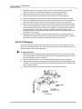
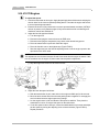
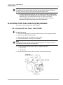
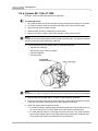
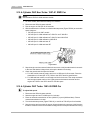
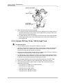
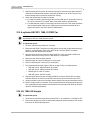
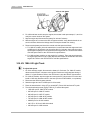
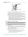
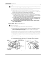
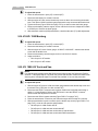
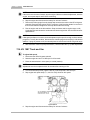
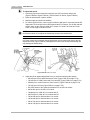
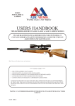
Ford Reference
F050
Subject:
Minimum idle speed adjustments for fuel-injected engines
Symptom: Erratic or incorrect idle speed, stalling, code 12, 13, 412, P0505, or P1505
Source:
Ford service manuals and service bulletins
This reference provides instructions for checking and adjusting the minimum idle speed for
most Ford fuel-injected engines. Also see Reference F069 for idle air bypass kit.
This reference contains the following procedures:
CENTRAL FUEL INJECTION (CFI) ENGINES
• “4-Cylinder CFI Engines” on page F153
• “3.8L V6 CFI Engines” on page F154
• “5.0L V8 CFI Engines” on page F155
ELECTRONIC PORT FUEL INJECTION (EFI) ENGINES
•
•
•
•
•
•
•
•
•
•
•
•
•
•
•
•
•
•
•
•
•
•
•
•
•
“1.6L 4-Cylinder EFI and Turbo: 1983–85 FWD” on page F156
“1.9L 4-Cylinder EFI: 1986–91 FWD” on page F157
“2.3L 4-Cylinder OHC Non-Turbo: 1987–91 RWD Car” on page F158
“2.3L 4-Cylinder OHC Turbo: 1983–89 RWD Car” on page F158
“2.3L 4-Cylinder OHC Non-Turbo: 1985–94 Light Truck” on page F159
“2.3L 4-cylinder HSC EFI: 1988–91 FWD Car” on page F160
“2.9L V6: 1986–89 Scorpio” on page F160
“2.9L V6: 1986–92 Light Truck 4.0L V6: 1986–91 Light Truck” on page F161
“3.0L V6: 1986–95 Light Truck” on page F162
“3.0L V6: 1986–90 Car (except Taurus SHO)” on page F163
“3.0L V6 SHO: 1989 and later Taurus” on page F164
“3.8L V6: 1988–92 Car” on page F165
“3.8L Supercharged V6: 1989–90 Thunderbird and Cougar” on page F166
“4.9L in-line 6-Cylinder: 1987 Truck and Van” on page F166
“4.9L in-line 6-Cylinder: 1988–89 Truck and Van” on page F167
“5.0L V8: 1985 Truck and Van” on page F168
“5.0L V8: 1986–87 Truck and Van” on page F168
“5.0L V8: 1988 and later Truck and Van” on page F169
“5.0L V8: 1986–87 RWD Car” on page F169
“5.0L V8: 1988–91 Car, except 1991 and later HO Mustang, Mark VII” on page F170
“5.0L V8 HO: 1991–94 Mustang and Mark VII” on page F170
“5.0L V8 HO: 1995 Mustang” on page F171
“5.8L V8: 1988–89 Truck and Van” on page F171
“7.5L V8: 1987 Truck and Van” on page F172
“7.5L V8: 1988 and later Truck and Van” on page F173
F151
F050
Ford Reference
MAZDA ELECTRONIC CONTROL SYSTEM (MECS)
• “2.0L 4-Cylinder EFI: Probe (1993 only)” on page F173
• “1.3L 4-Cylinder EFI: Festiva 1.6L 4-Cylinder EFI: Tracer 1.8L 4-Cylinder EFI: Escort GT
2.0L 4-Cylinder EFI: Probe (Except 1993) 2.2L 4-Cylinder EFI and Turbo: Probe 2.5L
6-Cylinder EFI Probe” on page F173
i
NOTE:
See Reference F053 or the Vehicle Communications Manual for additional instructions on
using the Scanner™ to assist in idle adjustment on some 1990 and later engines. See
Reference F068 for spout connector locations.
Before minimum idle speed adjustment on port injection systems, inspect the throttle body
and idle speed control (ISC) air bypass valve for sludge or varnish buildup. If sludge is
present, clean the valve in accordance with Reference F051 and Ford service procedures.
Observe the following precautions:
• Do not clean any 1993-later throttle bodies.
• Do not clean black plastic ISC assemblies or throttle bodies with idle air bypass kit.
• Do not clean either the throttle body or the idle air bypass valve if the throttle body has a
yellow and black ATTENTION label.
• Do not remove the plastic coating from the throttle plates and throttle body bore on a 2.2L
Probe engines.
After minimum idle speed adjustment, the electronic control assembly (ECA) idle speed
control program, or strategy, must be reset. The procedures in this reference include
instructions for this “idle learn” operation. These instructions must be followed in all cases, or
idle speed control will not be correct after adjustment. In some cases, it may be necessary to
drive the vehicle for the processor to learn the idle speed control program, or strategy.
Unless directed otherwise, the engine should be at normal operating temperature when
minimum idle speed is adjusted. Each Ford engine requires a specific procedure for minimum
idle speed adjustment and idle learning. The complete instructions must be followed exactly
for every engine.
CENTRAL FUEL INJECTION (CFI) ENGINES
This section contains procedures for all CFI engines.
Before adjusting idle speed, the idle speed control (ISC) motor must be retracted. Retract the
ISC motor in one of the following two ways:
z
Retracting the ISC motor using the Scanner™:
1. With the engine off, remove the air cleaner.
2. Select the KEY ON ENGINE OFF SELF TEST from the SERVICE CODES menu.
3. Watch for the ISC motor to retract and turn the ignition key off immediately.
4. Disconnect the ISC motor from the wire harness. (Some 3.8L engines do not have a
connector at the ISC motor. In these cases, be sure to leave the ignition off during idle
adjustment.)
F152
F050
Ford Reference
z
Retracting the ISC motor using the Scanner™:
1. :With the engine off, remove the air cleaner.
Connect a jumper wire between the self-test
input connector and the signal return (ground)
pin on the self-test connector
(Figure F050-1).
2. Turn the ignition key to RUN but do not start
the engine. The ISC plunger will retract in 10
to 15 seconds. If the plunger does not retract,
refer to a service manual and repair.
Figure F050-1
3. Return the ignition key to OFF and wait 10 to 15 seconds; then remove the jumper wire.
Disconnect the ISC motor from the wire harness. (Some 3.8L V6 engines do not have a
connector at the ISC motor. In these cases, be sure to leave the ignition switched off
during idle adjustment.)
4. Inspect the ISC wiring harness for exposed wires at the 4-wire connector. Repair as
necessary to prevent a short circuit.
4-Cylinder CFI Engines
z
To adjust idle speed:
1. With the ISC motor retracted and disconnected, start the engine and check the idle speed:
– 1.9L—625 ±25 rpm in drive (AT) or neutral (MT). If not within limits adjust the throttle
stop screw (Figure F050-2). Stop the engine and reconnect the ISC motor.
–
–
–
–
2.3L HSC—See reference F002 for information.
2.5L HSC, AT (1986–90) 650 ±25 rpm in drive.
2.5L HSC, MT (1986) 725 ±25 rpm in neutral.
2.5L HSC, MT (1987–90) 700 ±25 rpm in neutral.
If not within limits, continue with step 2. (Also see reference F028 for related service
information on 1986–87 models.)
2. If a plug is installed over the throttle stop screw, shut the engine off and remove the throttle
body from the engine.
3. Remove the plug that covers the throttle stop screw (Figure F050-3).
4. If the existing throttle stop screw is loose, secure it with Loctite® or replace it.
Figure F050-2
Figure F050-3
F153
F050
Ford Reference
5. Reinstall the throttle body on the engine but do not connect the ISC motor. Start the
engine, let it warm up to operating temperature. Let the idle speed stabilize.
6. Adjust the throttle stop screw (Figure F050-3) to the rpm specified in step 1.
7. Stop the engine and reconnect the ISC motor connector to the wiring harness.
8. Disconnect the battery for 10 minutes to erase the learned idle from EEC-IV memory.
9. Reconnect the battery and the ISC motor. Position a tachometer so it can be read from the
driver seat. Start the engine and let it idle for 2 minutes in park (AT) or neutral (MT).
10. With your foot on the brake to hold the vehicle, shift an automatic transmission into drive;
leave a manual transmission in neutral. Let the engine idle for 2 more minutes. The ISC
motor should then control the idle speed to the adaptive, or learned, speed as shown in
the specifications. In some cases, it may be necessary to drive the vehicle for the
processor to learn the new idle speed. (See Reference F002 for specification information
on 1985–87 2.3L engines.)
11. Step lightly on the accelerator to increase engine speed above idle; then release the
accelerator. The engine rpm should return to the adaptive (learned) idle speed, controlled
by the EEC-IV processor. Apply the parking brake and turn the key OFF.
3.8L V6 CFI Engines
Some 3.8L engines do not have a connector at the ISC motor. For these engines, turn the
ignition off immediately after the ISC motor retracts during the self-test mode and be sure to
leave the ignition off during idle adjustment.
z
To adjust idle speed:
1. With the ISC motor retracted and disconnected (if applicable), back out the throttle stop
screw until the throttle is closed and a 0.005-inch (0.13 mm) gap exists between the screw
tip and the throttle lever (Figure F050-4).
2. Then turn the screw back in 1-1/2 turns and seal the threads to prevent movement.
3. Adjust the ISC motor by loosening the lock screw and turning the bracket adjusting screw
to obtain a 7/32-inch gap between the ISC motor tip and the throttle lever (check the gap
with a 7/32-inch drill bit).
4. Tighten the ISC bracket lock screw and reconnect the ISC motor harness.
Figure F050-4
F154
F050
Ford Reference
5.0L V8 CFI Engines
z
To adjust idle speed:
1. Connect a tachometer to the engine. Apply the parking brake and disconnect and plug the
vacuum hose for the vacuum-operated parking brake. Then start the engine and warm it
to normal operating temperature.
2. Ensure that vacuum is not present at the vacuum-operated throttle modulator (VOTM). If
vacuum is present, verify that the engine is fully warm and that all air conditioning and
ventilation controls are switched off.
3. Adjust the fast idle speed as follows:
a. Turn the engine off.
b. Disconnect and plug the vacuum hose at the EGR valve.
c. Disconnect and plug the evaporative purge hose at the throttle body spacer.
d. Place the transmission in park and restart the engine.
e. Place the fast-idle cam on the highest step (Figure F050-5).
f. Start the engine and turn the fast-idle adjusting screw to set the engine speed to the
rpm listed on the VECI decal.
i
NOTE:
This adjustment must be done between 20 and 60 seconds after the engine is started. If this
time is exceeded, turn the engine off; then restart it and repeat the adjustment
g. Stop the engine and reconnect all vacuum hoses
Figure F050-5
Figure F050-6
4. Adjust the curb idle speed as follows:
a. With the transmission in park, start and run the engine at 2000 rpm for 60 seconds.
b. Block the drive wheels and ensure that the parking brake is applied. Do not apply the
service brakes because engine speed may change.
c. Let the engine return to idle and allow the idle speed to stabilize. Then place the
transmission in drive. Check the idle speed on the tachometer.
d. If curb idle speed is above 550 rpm, loosen the saddle-bracket lock screw and adjust
the idle speed by turning the adjusting screw counterclockwise (Figure F050-6).
Repeat procedure.
F155
F050
Ford Reference
i
NOTE:
This adjustment must be done within 2 minutes after the engine is started. If this time is
exceeded, turn the engine off; then restart it and repeat the adjustment
e. If curb idle speed is below 550 rpm, turn the engine off, loosen the saddle-bracket
lock screw, and turn the adjusting screw one turn clockwise. Tighten the lock screw,
restart the engine, and repeat steps a through c to check the idle speed.
f. If the idle speed adjustment in step e or d is greater than 50 rpm, check the
transmission linkage and throttle position sensor adjustments.
ELECTRONIC PORT FUEL INJECTION (EFI) ENGINES
This section contains procedures for all EFI engines.
1.6L 4-Cylinder EFI and Turbo: 1983–85 FWD
z
To adjust idle speed:
1. Disconnect and plug both vacuum lines at the EGR valve vacuum regulator solenoid.
2. Disconnect the ISC air bypass solenoid.
3. Start the engine and run it at 2000 rpm for 60 seconds.
4. Place the transmission in drive (AT) or neutral (MT).
i
NOTE:
The engine cooling fan must be running during idle adjustment and adjustment must be
completed within 2 minutes after returning to idle.
5. Turn the throttle stop screw (Figure F050-7), to adjust idle speed to:
– 600 rpm (MT)
– 750 rpm (AT).
6. Stop the engine and reconnect all vacuum lines and electrical connectors.
Figure F050-7
F156
F050
Ford Reference
1.9L 4-Cylinder EFI: 1986–91 FWD
Be aware, 1992–later SEFI idle speed is not adjustable
z
To adjust idle speed:
1. On all SEFI engines and all 1991 and later models, disconnect the battery for 5 minutes.
2. On 1986–87 models, disconnect and plug both EGR valve vacuum solenoid lines.
3. Disconnect the ISC air bypass solenoid.
4. Start the engine and run it at 2000 rpm for 60 seconds.
5. Place an AT in drive (1986) or park (1987 and later). Place a MT in neutral.
i
NOTE:
Adjustment must be completed within 2 minutes after returning to idle. The engine cooling fan
must be running during idle adjustment (1986–87).
6. Turn the throttle stop screw (Figure F050-8), to adjust idle speed to:
–
–
–
–
800 ±50 rpm (1986 AT)
900 ±50 rpm (other 1986–87 models)
950 ±50 (1988–90)
600 ±25 (1991).
Figure F050-8
i
NOTE:
After a period of engine running time, idle speed may change because of idle control strategy.
7. Stop the engine and repeat steps 3, 4, and 5 to verify minimum idle speed.
8. Reconnect all vacuum lines and electrical connectors. Verify that the throttle is not stuck
in the bore and that the linkage does not keep the throttle from closing.
9. Check the normal curb idle speed as follows:
a. For 1986–87 models, start the engine and run it at 2000 rpm for 60 seconds. Place an
AT in drive. Place a MT in neutral. Refer to the VECI decal for specifications.
b. For 1988 and later models, run the engine at idle for 2 minutes. Then snap accelerate
and let engine speed return to idle. Lightly depress and release the accelerator and
let the engine idle. Refer to the VECI decal for specifications.
F157
F050
Ford Reference
2.3L 4-Cylinder OHC Non-Turbo: 1987–91 RWD Car
i
NOTE:
See Reference F053 for 1992 and later models.
1. On 1991 models, disconnect the battery for 5 minutes.
2. Disconnect the ISC air bypass solenoid.
3. Run the engine at 1500 rpm for 30 seconds.
4. With the transmission in neutral, turn the throttle stop screw (Figure F050-9) to set the idle
speed. Adjust to:
–
–
–
–
–
–
525 ±25 rpm for all 1987 models
525 ±25 rpm for 1988 calibrations 7-05A-R11 and 7-06A-R11
650 ±25 rpm for 1988 calibrations 7-06A-R10 and 8-06A-R10
600 ±25 rpm for 1988 calibration 8-05A-R10
650 ±25 rpm for 1989 and later AT
600 ±25 rpm for 1989 and later MT
Figure F050-9
5. Stop the engine and reconnect all electrical connectors. Verify that the throttle is not stuck
in the bore and that the linkage does not keep the throttle from closing.
6. Check the normal curb idle speed as follows:
a. For 1987 models, start the engine and run it at 1500 rpm for 20 seconds. Place the
transmission in neutral (MT or AT). Refer to the VECI decal for specifications.
b. For 1988 and later models, run the engine at idle for 2 minutes. Then snap accelerate
and let engine speed return to idle. Lightly press and release accelerator and let
engine idle. Refer to the VECI decal for curb idle specs.
2.3L 4-Cylinder OHC Turbo: 1983–89 RWD Car
z
To adjust idle speed:
1. Disconnect the ISC air bypass solenoid.
2. Start the engine and run it at 2000 rpm for 2 minutes.
3. Place an automatic transmission in drive (1986–87) or park (1988 and later). Place a
manual transmission in neutral.
4. Turn the throttle stop screw (Figure F050-10), to set idle to 750 ±25 rpm for all models.
5. Stop the engine and reconnect all vacuum lines and electrical connectors. Verify that the
throttle is not stuck in the bore and that the linkage does not keep the throttle from closing.
F158
F050
Ford Reference
Figure F050-10
6. Check the normal curb idle speed as follows:
a. For 1983–87 models, start the engine and run it at 1500 rpm for 20 seconds. Place an
automatic transmission in drive. Place a manual transmission in neutral. Refer to the
VECI decal for curb idle specifications.
b. For 1988 and later models, run the engine at idle for 2 minutes. Then snap accelerate
and let engine speed return to idle. Lightly depress and release the accelerator and
let the engine idle.
2.3L 4-Cylinder OHC Non-Turbo: 1985–94 Light Truck
z
To adjust idle speed:
1. On 1991 and later models, disconnect the battery for 5 minutes.
1994 Only—Disconnect the SPOUT connector near the ignition module and verify that
base timing is within ±2° of specification. Refer to the VECI decal. Leave the SPOUT
connector disconnected until adjustment is finished.
2. Disconnect the ISC air bypass solenoid, which is mounted on the air cleaner of 1985–88
models and on the throttle body of 1989 and later models.
3. For 1989 and later models, disconnect the SPOUT connector near the self-test connector
and verify that base timing is within ±2° of specifications. Refer to the VECI decal. Leave
the SPOUT connector disconnected until adjustment is finished.
4. Run the engine at 2500 rpm for 30 seconds with the transmission in neutral or park.
5. Place an AT in drive (1985–87) or park (1988 and later). Place a MT in neutral.
6. Turn the throttle stop screw (Figure F050-9 on page F158), to set idle speed to the
specification listed below:
–
–
–
–
–
575 ±25 rpm for all 1985–87 and 1989–90 models
625 ±25 rpm for all 1988 models
550 ±25 rpm for all 1991 models
650 ±150 rpm for 1992-94 AT models
600 ±150 rpm for 1992-94 MT models
F159
F050
Ford Reference
7. Stop the engine and reconnect all electrical connectors. Reconnect the ignition SPOUT
connector on 1989 and later models. Verify that the throttle is not stuck in the bore and
that the linkage does not keep the throttle from closing.
8. Check the normal curb idle speed as follows:
a. For 1986–87 models, start the engine and run it at 1500 rpm for 30 seconds. Place an
AT in drive. Place a MT in neutral. Refer to the VECI decal for specifications.
b. For 1988 and later models, run the engine at idle for 2 minutes. Then snap accelerate
and let engine speed return to idle. Lightly press and release accelerator and let
engine idle. Refer to the VECI decal for specifications.
2.3L 4-cylinder HSC EFI: 1988–91 FWD Car
i
NOTE:
See Reference F053 for 1992 and later models
z
To adjust idle speed:
1. On 1991, disconnect the battery for 5 minutes.
2. Disconnect the SPOUT connector near the ignition module and verify that base timing is
within ±2° of specification. Refer to the VECI decal. Leave the SPOUT connector
disconnected until adjustment is finished.
3. Stop the engine and remove the PCV hose at the PCV valve and install a 0.200-inch
diameter orifice in the hose (Ford tool T86P-9600-A, or equivalent).
4. Disconnect the ISC air bypass solenoid.
5. Start the engine and run it at 2500 rpm for 30 seconds.
6. Place the transmission in drive (AT) or neutral (MT).
7. Turn the throttle stop screw (Figure F050-10 on page F159), to set idle speed to:
–
–
–
–
1025 ±50 rpm for 1990 and earlier AT models
1550 ±50 rpm for 1990 and earlier MT models
950±25 rpm for 1991 AT models
1550 ±25 rpm for 1991 MT models
8. Stop the engine and reconnect the ignition SPOUT connector and the ISC air bypass
solenoid. Remove the orifice from the PCV hose and reconnect the hose to the valve.
9. Verify the throttle is not stuck in the bore and the linkage does not prevent throttle closing.
10. Run the engine at idle for 2 minutes. Then snap accelerate and let engine speed return to
idle. Lightly depress and release the accelerator and let the engine idle. Refer to the VECI
decal for curb idle specifications.
2.9L V6: 1986–89 Scorpio
z
To adjust idle speed:
1. Set electronic automatic temperature control (EATC)— air conditioner—to ECON or OFF.
2. Remove the tamper proof cap from the throttle stop screw and throw it away. Then loosen
the locknut on the throttle stop screw.
F160
F050
Ford Reference
3. Loosen the throttle camplate roller bolt
(Figure F050-11).
4. Disconnect the ISC air bypass solenoid
electrical connector.
5. Run the engine at 2000 rpm for 30 seconds.
6. Slowly let the engine return to idle and place
the transmission in neutral
7. Set idle speed to 725 ±25 rpm by turning the
throttle stop screw, then tighten the locknut.
8. When tightening the throttle camplate roller
bolt, be sure the throttle stop still contacts
the throttle stop screw. With the throttle
open, be sure there should not be excessive
lost motion in the throttle pedal.
Figure F050-11
9. Increase engine speed to 2000 rpm for
about 30 seconds; then let it return to idle. Repeat this one more time to be sure the
throttle plates move freely.
10. Turn the engine off and reconnect the ISC air bypass solenoid electrical connector.
11. Move the throttle plates and check to be sure that they are not sticking in the bores.
12. Restart the engine and set the EATC to OFF or ECON.
13. Increase engine speed to 2000 rpm for 1-1/2 seconds and release the throttle. Place an
AT in drive or a MT in neutral, and let the engine idle for 3 minutes.
14. Turn the EATC to ON and let the engine idle for another 3 minutes in drive or neutral.
15. Place an AT in park and let the engine continue to idle for another 3 minutes.
i
NOTE:
See Reference F036 for related service information on 1988–89 models.
2.9L V6: 1986–92 Light Truck
4.0L V6: 1986–91 Light Truck
z
To adjust idle speed:
1. On 1991 and later models, disconnect the battery for 5 minutes.
2. Disconnect the ISC air bypass solenoid.
3. Start the engine and run it at 2500 rpm for 30 seconds.
4. Place an AT in drive (AT) or park (all 1991 and later and 1990 2.9L), or MT in neutral.
5. Turn the throttle stop screw (Figure F050-12 on page F162), to set the idle speed:
–
–
–
–
–
–
–
700 ±25 rpm for 1986 and 1987 AT models
750 ±50 rpm for 1986 MT models
650 ±50 rpm for 1987 MT models
700 rpm for all 1988 models
725 ±25 rpm for all 1989–91 models except 4.0L
675 ±25 rpm for 1990–91 4.0L models
600 ±150 rpm for 1992 2.9L models
F161
F050
Ford Reference
Figure F050-12
6. For 1988 and later models, stop the engine; then restart it and repeat steps 2, 3, and 4 to
verify the correct minimum idle speed.
7. Stop the engine and disconnect the battery for at least 5 minutes.
8. With the engine off, reconnect the ISC air bypass solenoid. Verify that the throttle is not
stuck in the bore and that the linkage does not keep the throttle from closing.
9. Reconnect the battery and check the normal curb idle speed as follows:
a. For 1986–87 models, place the transmission in neutral and start the engine and run it
at 2000 rpm for 20 seconds. Let the engine idle for 2 minutes; then raise the engine
speed again to 2000 rpm for 20 seconds Let the engine idle for 1 minute and check the
curb idle speed. Refer to the VECI decal for specifications.
b. For 1988 and later models, run the engine for 2 minutes. Then snap accelerate and
let engine speed return to idle. Lightly depress and release the accelerator and let the
engine idle. Refer to the VECI decal for curb idle specifications.
3.0L V6: 1986–95 Light Truck
z
To adjust idle speed:
1. On 1991 and later models, disconnect the battery for 5 minutes. For 1986–87 models,
disconnect the SPOUT connector at the ignition module and verify that base timing is
within ±2° of specifications. Refer to the VECI decal. Leave the SPOUT disconnected.
2. For 1986–87 models, stop the engine and remove the PCV hose at the PCV valve and
install a 0.200-inch diameter orifice in the hose (Ford tool T86P-9600-A, or equivalent).
3. Disconnect the ISC air bypass solenoid.
4. Start the engine and run it at 2500 rpm for 30 seconds.
5. Place the transmission in drive (AT) or neutral (MT). Place 1991 and later AT in park.
6. Turn the throttle stop screw (Figure F050-13), to set the idle speed:
–
–
–
–
–
–
–
–
1040 ±25 rpm for 1986–87 MT models
845 ±25 rpm for 1986 AT models
900 ±25 rpm for 1987 AT models
625 ±25 rpm for 1988–90 AT models
725 ±25 rpm for 1988–90 MT models
600±25 rpm for all 1991 models
600 +75 or -50 for all 1992–94 models
600 ±50 rpm for 1995 Aerostar
F162
F050
Ford Reference
Figure F050-13
7. Stop the engine; then restart and repeat steps 4, 5, and 6 to verify minimum idle speed.
8. Stop the engine and disconnect the battery for at least 5 minutes.
9. With the engine off, reconnect the ISC air bypass solenoid. On 1986–87 models,
reconnect the ignition SPOUT connector and the PCV hose to the valve. Verify that the
throttle is not stuck in the bore and that the linkage does not keep the throttle from closing.
10. Reconnect the battery and check the normal curb idle speed as follows:
a. For 1986–87 models, start the engine and run it at 2000 rpm for 20 seconds. Let the
engine idle for 2 minutes; then raise the engine speed again to 2000 rpm for 20
seconds. Let the engine idle for 1 minute and check the curb idle speed. It should be
700 ±50 rpm in drive (At) or 800 ±50 rpm in neutral (MT).
b. For 1988 and later models, run the engine for 2 minutes. Then snap accelerate and
let engine speed return to idle. Lightly depress and release the accelerator and let the
engine idle. Curb idle speed should be 700 ±50 rpm (pre-1990 AT), 720±50 (1990
AT), or 800 ±50 rpm (MT). See VECI label to confirm specification.
3.0L V6: 1986–90 Car (except Taurus SHO)
i
NOTE:
For 1991 and later, use “Idle Speed Adjust” Functional Test. (See Reference F053.)
z
To adjust idle speed:
1. Disconnect the SPOUT connector at the ignition module and verify that base timing is
within ±2° of specifications. Refer to the VECI decal. Leave the SPOUT disconnected.
2. Remove the PCV hose at the PCV valve and install a 0.200-inch diameter orifice in the
hose (Ford tool T86P-9600-A, or equivalent).
3. Disconnect the ISC air bypass solenoid.
4. For 1988 and later models, start the engine and run it at 2000 rpm for 30 seconds.
5. Place the transmission in drive (AT) or neutral (MT).
6. Turn the throttle stop screw (Figure F050-13), to set the idle speed to specifications:
– 710 ±20 rpm for 1986 models with processor code EF7, LK7, or LM7
– 760 ±20 rpm for 1986 models with any other processor codes
– 760 ±20 rpm for all 1987 and later models
F163
F050
Ford Reference
i
NOTE:
All 1986 models—Open the glove box and inspect the paper tag on the rear of the processor
to find the code. Also see Reference F016 for related information.
7. Stop the engine and disconnect the battery for at least 5 minutes.
8. With the engine off, reconnect the ignition SPOUT connector and the ISC air bypass
solenoid. Reconnect the PCV hose to the valve. Verify that the throttle is not stuck in the
bore and that the linkage does not keep the throttle from closing.
9. Reconnect the battery and check the normal curb idle speed as follows:
a. For 1986–87 models, start the engine and run it at 2000 rpm for 2 minutes. Place AT
in drive. With processor codes EF7, LK7, or LM 7, curb idle speed should be 625 ±50
rpm. For all other models curb idle speed should be 700 ±50 rpm
b. For 1988 and later models, run the engine at idle for 2 minutes. Then snap accelerate
and let engine speed return to idle. Lightly depress and release the accelerator and
let the engine idle. Curb idle speed should be 700 ±50 rpm.
10. For models with automatic overdrive (AOD or AXOD) transmission, check the throttle
valve (TV) cable adjustment.
3.0L V6 SHO: 1989 and later Taurus
z
To adjust idle speed:
1. On 1991 and later models, disconnect the battery for 5 minutes.
2. Disconnect the SPOUT connector at the ignition module and verify that base timing is
within ±2° of specifications. Refer to the VECI decal. Leave the SPOUT connector
disconnected until adjustment is finished.
3. Stop the engine and disconnect the PCV hose from the upper intake manifold and plug it.
4. Disconnect the canister purge (CANP) hose from the intake manifold and install Ford tool
T89P-9600-AH, or equivalent made from vacuum hose, between CANP and PCV ports.
5. 1995 Only—Shut off engine and install a 0.025 inch feeler gauge between throttle lever
and return screw.
6. Disconnect the ISC air bypass solenoid.
7. Place the transmission in neutral, start the engine, and let idle speed stabilize.
8. Turn the throttle stop screw (Figure F050-14), to set the idle speed to 800 ±30 rpm.
Figure F050-14
F164
F050
Ford Reference
i
NOTE:
Idle speed may change because of idle control program, or strategy.
9. Stop the engine and repeat steps 5 and 6 to verify minimum idle speed.
10. Stop the engine and disconnect the battery for at least 5 minutes.
11. With the engine off, reconnect the ignition SPOUT connector, ISC air bypass solenoid,
and PCV and CANP hoses.
12. Verify that the throttle is not stuck in the bore and that the linkage does not keep the
throttle from closing.
13. Run the engine for 2 minutes.
14. Snap accelerate and let engine return to idle. Lightly depress and release the accelerator
and let the engine idle. Refer to the VECI decal for curb idle specifications.
3.8L V6: 1988–92 Car
i
NOTE:
For 1991 and later models, use Scanner™ “Idle Speed Adjust” Functional Test.
z
To adjust idle speed:
1. Place the transmission in park (AT) or neutral (MT).
2. With the engine off, back out the throttle stop screw so it is not touching the throttle lever.
3. Place a 0.010-inch feeler gauge between the throttle stop screw and the throttle lever.
4. Tighten the throttle stop screw (Figure F050-15), so that it touches the feeler gauge; then
turn it another 1-1/2 turns.
Figure F050-15
5. Run the engine at idle for 2 minutes.
6. Snap accelerate and let engine return to idle. Lightly depress and release the accelerator
and let the engine idle. Refer to the VECI decal for specifications.
7. With an AOD or AXOD transmission, check throttle valve (TV) cable adjustment.
F165
F050
Ford Reference
3.8L Supercharged V6: 1989–90 Thunderbird and Cougar
i
NOTE:
For 1991 and later models, use Scanner™ “Idle Speed Adjust” Functional Test.
z
To adjust idle speed:
1. Place the transmission in park (AT) or neutral (MT).
2. With the engine off, back out the throttle stop screw so that it is not touching the throttle
lever. Then place a 0.010-inch feeler gauge between the throttle stop screw and the
throttle lever.
3. Tighten the throttle stop screw (Figure F050-16), so that it touches the feeler gauge; then
turn it another 1-1/2 turns.
Figure F050-16
4. Run the engine for 2 minutes.
5. Snap accelerate and let engine return to idle. Lightly depress and release the accelerator
and let the engine idle. Refer to the VECI decal for curb idle specifications.
4.9L in-line 6-Cylinder: 1987 Truck and Van
z
To adjust idle speed:
1. Disconnect the battery for 5 minutes to erase the current idle control program from ECA
memory. Turn the throttle stop screw in (clockwise) 1 turn.
2. Reconnect the battery, place the transmission in neutral or park, and run the engine at
1800 rpm for 30 seconds.
3. Place the transmission in drive (AT) or neutral (MT) and let idle speed stabilize.
i
NOTE:
Adjustment must be completed within 30 seconds after returning to idle.
4. Back out the throttle stop screw (Figure F050-17 on page F167), to adjust idle speed to
600 ±20 rpm (AT) or 700 ±20 (MT). Then back the screw out an additional 1/2 turn.
F166
F050
Ford Reference
Figure F050-17
5. Stop the engine, disconnect the battery for 5 minutes, and repeat steps 2, 3, and 4 to
verify minimum idle speed.
6. To check the normal curb idle speed, start the engine and run it at 1800 rpm for 30
seconds. Place an automatic transmission in drive; place a manual transmission in
neutral. Let the engine idle for 1 minute. Refer to the VECI decal for curb idle
specifications.
4.9L in-line 6-Cylinder: 1988–89 Truck and Van
i
NOTE:
For 1990 and later models, use Scanner™ “Idle Speed Adjust” Functional Test.
z
To adjust idle speed:
1. With the engine off, place a 0.050-inch feeler gauge between the throttle stop screw and
the throttle lever.
2. Disconnect the SPOUT connector near the ignition module and verify that base timing is
within ±2° of specifications. Refer to the VECI decal. Leave the SPOUT connector
disconnected until adjustment is finished.
3. Disconnect the ISC air bypass solenoid (Figure F050-17).
4. Place the transmission in neutral or park. Start the engine and let it idle for 2 minutes.
5. With the transmission in neutral or park turn the throttle stop screw (Figure F050-17), to
set the idle speed to the correct specifications:
– 650 ±25 rpm for calibrations 7-52ER, 7-52KR, 7-52MR, 7-52QR, 7-52RR, 7-52ZR,
7-52JR, 7-72JR
– 750 ±25 rpm for all other calibrations before 1990
– 675±25 rpm for 1990 AT models
– 700±25 rpm for 1990 MT models
i
NOTE:
If the screw must be turned in, stop the engine. Make an estimated adjustment, start the
engine, and repeat steps 4 and 5 before continuing.
F167
F050
Ford Reference
6. Stop the engine and disconnect the battery for at least 5 minutes
7. Remove the feeler gauge from the throttle stop screw and reconnect the ISC air bypass
solenoid. Reconnect the ignition SPOUT connector. Verify that the throttle is not stuck in
the bore and that the linkage does not keep the throttle from closing.
8. Start the engine and let the idle speed stabilize. Then snap accelerate and let engine
speed return to idle. Lightly depress and release the accelerator and let the engine idle.
Refer to the VECI decal for curb idle specifications.
i
NOTE:
If idle speed oscillates or is erratic, the throttle plates may be open far enough to allow canister
purge flow. To verify, disconnect and plug the canister purge hose. Idle speed should stabilize.
If purge is present at idle, the throttle plates must be closed until the rough idle stops.
9. For automatic overdrive (AOD) transmission, check throttle valve (TV) cable adjustment.
5.0L V8: 1985 Truck and Van
z
To adjust idle speed:
1. Disconnect the battery for 3 minutes to erase the current idle control program from ECA
memory. Turn the throttle stop screw in (clockwise) 1 turn.
2. Reconnect the battery, start the engine, and run it at 1800 rpm for 30 seconds.
3. Place the transmission in drive (AT) or neutral (MT) and let idle speed stabilize.
4. Back out the throttle stop screw (Figure F050-17 on page F167), until idle speed is 600
±20 (AT) or 700 ±20 (MT). Then back out the screw another 1/2 turn.
5. Stop the engine and disconnect the battery for at least 3 minutes.
6. To check curb idle speed, start the engine and run it at 1800 rpm for 30 seconds. Place the
transmission in drive (AT) or neutral (MT) and let idle speed stabilize. Refer to the VECI
decal for curb idle specifications.
5.0L V8: 1986–87 Truck and Van
z
To adjust idle speed:
1. Disconnect the battery for 3 minutes to erase the current idle control program from ECA
memory. Turn the throttle stop screw in (clockwise) 1 turn.
2. Reconnect the battery, place the transmission in neutral or park, and run the engine at
1800 rpm for 30 seconds.
3. Place the transmission in drive (AT) or neutral (MT) and let idle speed stabilize.
i
NOTE:
Adjustment must be completed within 30 seconds after returning to idle.
4. Back out the throttle stop screw (Figure F050-17 on page F167) to adjust idle to 600 ±20
(AT) or 700 ±20 (MT) rpm.
5. Stop engine and repeat steps 2, 3, and 4 to verify minimum idle speed.
6. Stop the engine and disconnect the battery for at least 3 minutes
F168
F050
Ford Reference
7. To check the normal curb idle speed, start the engine and run it at 1800 rpm for 30
seconds. Place an automatic transmission in drive; place a manual transmission in
neutral. Let engine idle 1 minute. Refer to VECI decal for curb idle specs.
5.0L V8: 1988 and later Truck and Van
i
NOTE:
For 1991 and later models, use Scanner™ “Idle Speed Adjust” Functional Test.
z
To adjust idle speed:
1. For 1995, skip this step:
With the engine off, place a 0.050-inch feeler gauge (AT) or a 0.030-inch feeler gauge
(MT) between the throttle stop screw and the throttle lever.
2. Disconnect the SPOUT connector near the ignition module and verify that base timing is
within ±2° of specifications. Refer to the VECI decal. Leave the SPOUT connector
disconnected until adjustment is finished.
3. Disconnect the ISC air bypass solenoid (Figure F050-17 on page F167).
4. Place the transmission in neutral or park. Start the engine and let it idle for 2 minutes.
5. With the transmission in park or neutral, turn the throttle stop screw (Figure F050-17 on
page F167), to set the idle speed to 675 ±50 rpm for AT or 700 ±50 rpm for MT
i
NOTE:
If the screw must be turned in, stop the engine. Make an estimated adjustment, start the
engine, and repeat steps 4 and 5 before continuing.
6. Stop the engine and disconnect the battery for at least 5 minutes
7. Remove the feeler gauge from the throttle stop screw and reconnect the ISC air bypass
solenoid. Reconnect the ignition SPOUT connector. Verify that the throttle is not stuck in
the bore and that the linkage does not keep the throttle from closing.
8. Start the engine and let the idle speed stabilize. Then snap accelerate and let engine
speed return to idle. Lightly depress and release the accelerator and let the engine idle.
Refer to the VECI decal for curb idle specifications.
i
NOTE:
If idle speed oscillates or is erratic, the throttle plates may be open far enough to allow canister
purge flow. To verify the condition, disconnect the canister purge hose and plug it. Idle should
stabilize. If purge is present at idle, the throttle plates must be closed until the rough idle stops.
9. With automatic overdrive (AOD) transmission, check throttle valve (TV) rod adjustment.
5.0L V8: 1986–87 RWD Car
z
To adjust idle speed:
1. Disconnect the battery for 3 minutes to erase the current idle control program from ECA
memory. Turn the throttle stop screw in (clockwise) 1 turn.
2. Reconnect battery, place transmission in neutral or park, and run the engine at 1800 rpm
for 30 seconds.
F169
F050
Ford Reference
Figure F050-18
3. Place the transmission in drive (AT) or neutral (MT) and let idle speed stabilize.
4. Turn the throttle stop screw (Figure F050-18), to adjust idle speed to specifications:
– 575 ±20 rpm for base engine with AT
– 625 ±20 rpm for high output engine with AT
– 700 ±20 rpm for high output engine with MT
i
NOTE:
High-output engines are marked HO on the intake plenum.
5. Stop the engine and disconnect the battery for 3 minutes. Then repeat steps 2 and 3 to
verify the correct curb idle speed. Refer to the VECI decal for curb idle specifications.
5.0L V8: 1988–91 Car, except 1991 and later HO Mustang, Mark VII
z
To adjust idle speed:
1. Place the transmission in park (auto) or neutral (manual).
2. Disconnect the battery for at least 5 minutes.
3. With the engine off, back out the throttle stop screw so that it is not touching the throttle
lever. Then place a 0.010-inch feeler gauge between the stop screw and the throttle lever.
4. Tighten the screw (Figure F050-18 on page F170), so that it touches the feeler gauge;
then turn it another 1-1/2 turns (1988–90 HO engine) or 1-7/8 turns (base engine).
5. Reconnect the battery, start the engine, and run it at idle for 2 minutes. Then snap
accelerate and let engine speed return to idle. Lightly depress and release the accelerator
and let the engine idle. Refer to the VECI decal for curb idle specifications.
6. For automatic overdrive (AOD) transmission, check throttle valve (TV) cable adjustment.
5.0L V8 HO: 1991–94 Mustang and Mark VII
i
NOTE:
For other 1991 and later HO engines, see Reference F053.
F170
F050
Ford Reference
z
To adjust idle speed:
1. Place the transmission in park (AT) or neutral (MT).
2. Disconnect the battery for at least 5 minutes.
3. With the engine off, back out the throttle stop screw so that it is not touching the throttle
lever. Then place a 0.025-inch feeler gauge between the stop screw and the throttle lever.
4. Tighten the screw (Figure F050-18 on page F170), so that it touches the feeler gauge.
5. Reconnect the battery, start the engine, and run it at idle for 2 minutes. Adjust the curb idle
to 675±25 rpm. Remove the feeler gauge.
6. With automatic overdrive (AOD) transmission, check throttle valve (TV) cable adjustment.
5.0L V8 HO: 1995 Mustang
z
To adjust idle speed:
1. Place the transmission in park (AT) or neutral (MT).
2. Disconnect the battery for at least 5 minutes.
3. With the engine off, insert a feeler gauge—0.050 AT or 0.030 MT— between the throttle
screw and the throttle lever.
4. Reconnect the battery, start the engine, and run it at idle for 2 minutes.
5. Adjust curb idle to:
– 704 +10 rpm for AT models
– 604 +10 rpm for MT models
5.8L V8: 1988–89 Truck and Van
i
z
NOTE:
For 1990 and later models under 8500 GVW, and all 1992 models see Reference F053 for
Scanner™ “Idle Speed Adjust” Functional Test. Some 1990 and later models over 8500 GVW
also may have “Idle Speed Adjust” Functional Test available. If not, use this procedure.
To adjust idle speed:
1. With the engine off, place a 0.030-inch feeler gauge between the throttle stop screw and
the throttle lever (0,050-inch for 1991 and later AT).
2. Disconnect the SPOUT connector at the ignition module and verify that base timing is
within ±2° of specifications. Refer to the VECI decal. Leave the SPOUT connector
disconnected until adjustment is finished.
3. Disconnect the ISC air bypass solenoid (Figure F050-17 on page F167).
4. Place the transmission in neutral or park. Start the engine and let it idle for 2 minutes.
5. With the transmission in park or neutral, turn the throttle stop screw (Figure F050-17 on
page F167), to set the idle speed to specifications:
–
–
–
–
780 ±50 rpm for 1988 models with AT
730 ±50 rpm for 1988 and later models with MT
780 ±50 rpm for 1989 and later models with C6 transmission
730 ±50 rpm for 1989 and later models with E4OD transmission
F171
F050
Ford Reference
i
NOTE:
If the screw must be turned inward, stop the engine. Make an estimated adjustment, start the
engine, and repeat steps 4 and 5 before continuing.
6. Stop the engine and disconnect the battery for at least 5 minutes
7. Remove the feeler gauge from the throttle stop screw and reconnect the ISC air bypass
solenoid. Reconnect the ignition SPOUT connector. Verify that the throttle is not stuck in
the bore and that the linkage does not keep the throttle from closing.
8. Run the engine and let the idle stabilize. Snap accelerate and let engine return to idle.
Lightly depress and release the accelerator and let the engine idle. See the VECI decal for
specifications.
i
NOTE:
If idle speed oscillates or is erratic, the throttle plates may be open far enough to allow canister
purge flow. To verify the condition, disconnect the canister purge hose and plug it. Idle should
stabilize. If purge is present at idle, the throttle plates must be closed until the rough idle stops.
9. With automatic overdrive (AOD) transmission, check throttle valve (TV) cable adjustment.
7.5L V8: 1987 Truck and Van
z
To adjust idle speed:
1. Disconnect the ISC air bypass solenoid.
2. Start the engine and run it at 1800 rpm for 20 seconds.
3. Place the transmission in drive (auto) or neutral (manual).
i
NOTE:
Adjustment must be completed within 30 seconds after returning to idle.
4. Turn the throttle stop screw (Figure F050-19), until idle speed is 650 ±20 rpm.
5. Stop engine and repeat steps 1, 2, and 3 to verify minimum idle speed.
Figure F050-19
6. Stop the engine and disconnect the battery for at least 3 minutes
F172
F050
Ford Reference
7. To check the normal curb idle speed, reconnect the battery and the ISC air bypass
solenoid. Then start the engine and run it at 1800 rpm for 30 seconds. Place an AT in
drive; place a MT in neutral. Let the engine idle for 1 minute. Refer to the VECI decal for
curb idle specifications.
7.5L V8: 1988 and later Truck and Van
z
To adjust idle speed:
1. Disconnect the ISC air bypass solenoid.
2. Start the engine and run it at 2500 rpm for 30 seconds.
3. Place the transmission in park or neutral.
4. Turn the throttle stop screw (Figure F050-19 on page F172), to set the idle speed to:
– 650 ±50 rpm for 1992 and earlier AT models
– 650 ±25 rpm for 1992 and earlier MT models
– 650 ±150 rpm 1993 and later models (AT or MT)
5. Stop the engine and disconnect the battery for at least 5 minutes
6. Reconnect the ISC air bypass solenoid. Verify that the throttle is not stuck in the bore and
that the linkage does not keep the throttle from closing.
7. Run the engine and let the idle speed stabilize. Snap accelerate and let engine return to
idle. Lightly depress and release the accelerator and let the engine idle. Refer to the VECI
decal for curb idle specifications.
MAZDA ELECTRONIC CONTROL SYSTEM (MECS)
This section contains procedures for all MECS engines except the Probe 3.0L.
2.0L 4-Cylinder EFI: Probe (1993 only)
z
To adjust idle speed:
1. Disconnect the idle air solenoid.
2. Start the engine and run it at 2500 rpm for 30 seconds.
3. Adjust the idle to 650 to 750 rpm.
4. Reconnect the idle air solenoid.
– 1.3L 4-Cylinder EFI: Festiva
1.6L 4-Cylinder EFI: Tracer
1.8L 4-Cylinder EFI: Escort GT
2.0L 4-Cylinder EFI: Probe (Except 1993)
2.2L 4-Cylinder EFI and Turbo: Probe
2.5L 6-Cylinder EFI Probe
For Probe with 3.0L engine, see Reference F053 or use the Scanner™ “Idle Speed Adjust”
Functional Test.
F173
F050
Ford Reference
z
To adjust idle speed:
1. Connect a jumper wire between the self-test input (STI) connector and ground
(Figure F050-20 to Figure F050-24). (TEN connector on Escort, Figure F050-22)
2. Place the transmission in park or neutral.
3. Start the engine and let the idle stabilize.
4. For 1990 4-cylinder Probe, run the engine at 2500 to 3000 rpm for 3 minutes with the STI
ungrounded. Then verify the fan is off and ground the STI connector. For all 1991 and later
models, warm up the engine at 3000 rpm in neutral. For 1992 2.2L Probe and Turbo
Probe, run the engine until fan turns on.
i
NOTE:
On Festiva models, do not adjust the throttle stop screw on the throttle lever.
IMPORTANT:
On Tracer models, do not tamper with the adjustment screw located to the right of the idle
adjustment screw (Figure F050-20). Misadjustment of this screw will affect driveability and
may damage the throttle body.
Figure F050-20 Festiva and Tracer
5. Adjust the idle air bypass adjustment screw, to obtain the following idle speeds:
–
–
–
–
–
–
–
–
–
–
–
–
850 ±50 rpm for pre-1990 Festiva and Tracer (Figure F050-20 on page F174)
700 ±20 rpm for 1990 Festiva and Tracer with MT (Figure F050-20 on page F174)
850±20 rpm or 1990 Festiva and Tracer with AT (Figure F050-20 on page F174)
750 ±25 rpm for Probe (Figure F050-21 on page F175)
See VECI decal for idle speed specifications for all 1991–92 models
800 to 900 rpm for all 1993 1.3L models
700-800 rpm for 1994–95 1.3L models with AT
650-750 rpm for 1994–95 1.3L models with MT
700 to 800 rpm for 1993 and later 1.6L models
700 to 800 rpm for 1993 and later 1.8L models
650 to 750 rpm for 1993 and later 2.0L models
600 to 700 rpm for 1993 and later 2.5L models
F174
F050
Ford Reference
Figure F050-21 Probe
6. Stop the engine and disconnect the jumper wire from the self-test input connector.
For a Probe with a rolling idle, refer to the Troubleshooter tip for “idles rough, steering wheel
vibrates”. Turn the idle air adjustment screw clockwise to increase idle speed to 1000 rpm.
Then verify that the ISC motor is controlling rpm to the upper limit of the specification.
Figure F050-22 Escort GT (adjustment location is similar to Festiva and Tracer)
Figure F050-23 2.0L MECS
Figure F050-24 1.6L MECS
F175