1
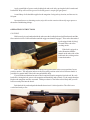
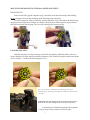
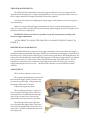
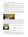
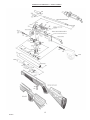
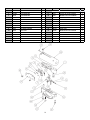
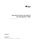
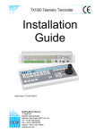
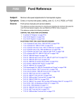
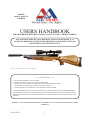
MODEL
S410 CLASSIC &
CARBINE
USERS HANDBOOK
THIS HANDBOOK REFERS TO S410S CLASSIC & S410C CARBINE MODELS
PLEASE READ THIS MANUAL BEFORE USING YOUR NEW RIFLE, IT
CONTAINS IMPORTANT SAFETY INFORMATION AND INSTRUCTION ON
ADJUSTMENT AND MAINTENANCE.
Model shown with optional scope and moderator.
***** SAFETY CODE *****
1 - TREAT THIS AIR RIFLE AS IF LOADED.
2 - NEVER POINT IT AT ANYONE, EVEN IF UNLOADED.
3 - NEVER LEAVE THIS RIFLE UNATTENDED WHEN COCKED OR LOADED.
4 - ALWAYS BE SURE OF WHAT LIES BEYOND YOUR TARGET.
5 - ALWAYS CONDUCT YOURSELF IN A SPORTSMAN-LIKE MANNER.
ALWAYS BE AWARE THAT YOUR ACTIONS WILL BE UNDER THE SCRUTINY OF OTHER MEMBERS
OF THE PUBLIC WHO MAY NOT SHARE YOUR ENTHUSIASM FOR AIR WEAPONS. BAD PRACTICES
PROMOTE BAD PUBLICITY. DO NOT JEOPARDISE YOUR FUTURE ENJOYMENT BY MISUSING THIS
WEAPON.
WARNING ! - UNAUTHORISED DISASSEMBLY OF THIS RIFLE WILL INVALIDATE THE MANUFACTURERS
WARRANTY
S410 ISS12
1
Contents of Box.
1
x
S410 Rifle.
1
x
Toll kit consisting of:
1
x
Manual.
1 x 1.5mm allen key
1 x 2.5mm allen key
1 x female filling adaptor.
Contents
Important information
Barrel cleaning
Lubrication
Cocking
Loading
Trigger adjustment
Manual safety
Filling instruction
Parts list
Page 3
Page 5
Page 5
Page 6
Page 7
Page 8
Page 9
Page 10
Page 12
2
IMPORTANT INFORMATION, PLEASE READ
Before leaving the factory this rifle was Q.A. inspected and test fired using Air Arms PELLETS
to check operation and final adjustment.
It was dispatched in a sealed purpose designed box with a contents label on the lid. Air Arms
may not be responsible for any damage to the contents or missing items if the box is not original, if it
is damaged or the seals are not intact.
Air Arms cannot be held responsible for damage or missing items due to transit damage, mishandling or being tampered with after leaving the factory.
If this rifle is not received in the original box with the seals intact, please examine carefully for
any damage, missing tools or documentation.
In the first instance any problems or complaints regarding this product should be referred to
the supplier.
The air cylinder is a highly pressurised unit that must not be modified in any way. Serious
personal injury may result if this, and the advice below is not followed.
Do not pressurise the cylinder if there are any surface abrasions or dents. Contact Air Arms for
advice.
Do not store the rifle in places with, or near sources of high temperature such as fires or
boilers.
Do not attempt to dismantle when pressurised.
Do not pressurise beyond the stated filling pressure (see filling instruction section). Damage
caused by such action is not covered by the manufacturers warranty.
Only use clean, filtered and dry compressed air. Never use any other gas, particularly industrial or welding gases such as oxygen, carbon dioxide, acetylene, hydrogen, argon, etc.
If compressed air is being used other than from a diving shop, the inside of the cylinder should
be inspected for corrosion at least annually. If in doubt contact Air Arms for advice.
In any event the cylinder should be inspected every two to three years depending upon usage.
Air Arms can provide this service at a reasonable cost.
To maintain this rifle in good working order it should be serviced annually by a competent
gunsmith, your supplier may be able to provide this service or contact air arms.
A reasonable amount of advice will be provided to enable the end user to service their own
rifle, however this is at the discretion of Air Arms and may not be given in all cases.
The velocity of this rifle has been set using Air Arms field pellets. If any other make or type of
pellet is to be used the rifle must be re-tested with the pellet that is to be used, to ensure the muzzle
energy is within the limits determined by current legislation.
Due to the nature of hand pumps and their relative inefficiency in removing moisture from the
compressed air , the chances of corrosion damage to the cylinder and other internal components are
increased. Therefore the rifle should be regularly serviced and/or checked for any signs of damage
by a competent gunsmith.
Air Arms recommend using a dry pack filter kit on any hand pumps used to fill our air rifles.
If accessories not manufactured by Air Arms are used on this rifle, Air Arms can not be held
responsible for any loss of performance.
Contact your supplier or Air Arms for any advice on this matter.
3
Important information continued.
CHECKING VELOCITY
1
2
3
Use a reliable chronograph to check velocity, (the formula below requires the reading to be in
feet per second - FPS)
Use fine measurement scales to weigh the pellet, If scales are unavailable the pellet weight may
be stated on the pellet container lid or contact the supplier. (The formula requires the weight to
be in grains). To convert from grams to grains multiply by 15.432, i.e. 0.69 grams x 15.432 =
10.65 grains.
To find the muzzle energy in ft/lbs use the formula (FPSxFPSxGrains)/450240, i.e.
(700x700x10.65) = 5218500 divide by 450240 = 11.59.
CURRENT LEGISLATION LIMITS NON-FAC HOLDERS, IN THE UK, TO AIR RIFLES WITH A MAXIMUM
OF 12ft/lbs MUZZLE ENERGY.
WARNING ! IT IS A VERY SERIOUS OFFENCE TO BE IN POSSESSION OF AN AIR RIFLE THAT YOU
ARE NOT CERTIFICATED FOR. CONVICTION CAN RESULT IN CONFISCATION OF YOUR RIFLE, A
HEAVY FINE OR IMPRISONMENT, EVEN A COMBINATION OF ALL THREE.
Do not store this rifle in a damp place such as garden shed or garage.
Do not store this rifle in a plastic or PVC gun bag without first applying a surface corrosion
inhibitor.
Always ensure the loading bolt is fully closed before firing.
***** LIMITED LIABILITY WARRANTY *****
UK Customers only.
This product is warranted to the retail customer for 12 months from date of purchase against defects in
materials and workmanship and is transferable to any subsequent owner.
Proof of purchase is required to receive warranty repairs, retain your purchase invoice and return the
warranty registration card as soon as possible after purchase. The warranty card must show the
dealer/supplier name and address and date of purchase.
What is covered
Replacement parts & labour on a ‘back to base’ basis, return transportation to the
consumer (mainland UK only).
What is not covered
Transportation from the consumer to Air Arms.
Damage caused by misuse, abuse, lack of routine maintenance, transit damage between
the dealer/supplier and the consumer or unauthorised disassembly.
Parts subject to normal wear and tear.
Any other consequential cost incurred by the consumer.
Return transportation to consumers outside mainland uk.
No warranty is implied as to the fitness for any particular purpose.
AIR ARMS RESERVE THE RIGHT TO ALTER THE CONSTRUCTION, APPEARANCE OR PERFORMANCE OF ANY PRODUCT WITHOUT PRIOR NOTIFICATION. ALL
ILLUSTRATIONS ARE FOR INFORMATION PURPOSES ONLY AND DO NOT NECESSARILY SHOW THE EXACT MODEL THAT WAS PURCHASED.
4
GENERALMAINTENANCEAND LUBRICATION
MAINTENANCE
FIXINGS
Regularly check the tightness of all fixings. However do not be tempted to over tighten as some
parts are made from aluminium and stripped threads may result. Stripped threads are not covered by
the manufacturers warranty.
BARREL
For ultimate accuracy, clean and re-lube the barrel frequently. It is difficult to advise how often
is best for every circumstance, but every 250 shots is not too often if the desire is to keep the barrel
in the best possible condition.
The correct materials are very important. Air arms only uses products made by napier. Listed
below is the napier product and a more generally available alternative. If possible use napier for the
best results.
CLEANER :
OIL :
PULL-THROUGH PAD :
PULL-THROUGH LINE :
‘NAPIER GUN CLEANER’, ALTERNATIVELY WHITE SPIRIT.
‘NAPIER GUN OIL’, ALTERNATIVELY ‘3 IN 1’ OIL.
‘NAPIER RIFLE CLEAN’, ALTERNATIVELY SOFT COTTON CLOTH.
‘NAPIER PULL THROUGH KIT’ , ALTERNATIVELY 20lb FISHING LINE
As a rule cleaners and oils intended for shotguns and small/fullbore weapons are not
suitable.
1
2
3
4
5
6
Cut a piece of line three times the length of your barrel, fold in half and tie ends together.
Remove silencer if fitted. Open loading bolt.
Feed un-knotted end down barrel from the muzzle end until folded end protrudes out
50mm.
Cut a 100mm length of ‘rifle clean’ or 100x50mm piece of cloth and pass it between the
protruding loop. Spray the pad with ‘gun cleaner’ or white spirit, turn the rifle upside
down and pull the line back through the barrel slowly.
Repeat steps 2&3 until the pad is clean.
Repeat steps 2&3 once more without any cleaner on the pad to dry the barrel.
Repeat steps 2&3 once more with the pad sprayed with ‘gun oil’ or 3 in 1 oil.
IMPORTANT : THE REASON FOR TURNING THE RIFLE UPSIDE DOWN IS
TO PREVENT EXCESS CLEANER/OIL FROM PASSING DOWN THE TRANSFER
PORT INTO THE FIRING VALVE CHAMBER.
LUBRICATION
MOVE
DAB GREASE
Lubrication of the
internal mechanism is not
covered in this handbook.
This is best performed by a
competent gunsmith or the
factory and in any case should
not be required until the
annual service.
5
MOVE
DAB
GREASE
HERE
HERE
Apply a small dab of grease on the loading bolt and work-in by moving the bolt forwards and
backwards. Wipe off excessive grease. Preferred grease is ‘napier g95 gun grease’.
A small drop of oil should be applied to the magazine O ring to keep it moist, and increase its
life span.
On return from every shooting session, wipe all over the exterior with an oily rag to preserve
the surface finish during storage.
OPERATING INSTRUCTIONS
COCKING
Hold securely in one hand and with the other turn the loading bolt and pull backwards until the
first restriction is felt. Pull back further until the trigger mechanism engages. This can be determined
by the trigger blade ‘kicking’
forward at the end of the
cocking stroke.
If the bolt is gripped as
in the illustration with the
thumb on the other side of the
bolt knob, the cocking action
is much smoother.
Note ! It is very important that the loading bolt is pulled back to the correct position. In one
positive motion. The magazine indexes to the next pellet position as the bolt is. Retracted and it is
possible for a partial index if the bolt is not pulled back fully.
If you find the mechanism has not cocked completely but the magazine has indexed, Re-cock
but before closing the bolt, remove the magazine and manually index it back . To the empty chamber.
Replace the magazine and fire as normal. If this procedure is. Not followed it is likely that you will
load a second pellet into the barrel.
Push the bolt forward and push the handle down into it’s locked position. The rifle is now
cocked and ready to fire.
6
MOUNTING/DEMOUNTING THE MAGAZINE & PELLETS
DEMOUNTING
Fully cock the rifle, grip the magazine as fig.1 and slide out of the bolt housing without lifting.
Do not attempt to lift vertically as damage to the indexing spring will result.
To refit the magazine, fully cock the rifle, grip the magazine as fig.2 and slide in the bolt housing
applying downward pressure with the fore finger to keep the base of the magazine against the bottom of the slot in the bolt housing. Take care not to damage the indexing spring.
LOADING PELLETS
Hold the magazine as in fig.3 and drop a pellet into the chamber. Manually index to the next
empty chamber as in fig.4 and repeat until the magazine is full. Finally line up the red dot on the pellet
carrier with the ‘v’ notch on the clear magazine cover.
Be very careful not to damage the indexing spring when
demounting or mounting the magazine. Follow the instructions
carefully.
WARNING. The rifle should only be fired when the magazine is
fitted in the breech or damage to the seal carrier may occur.
A small drop of oil should be applied to the magazine
O ring to keep it moist, and increase its life span.
7
TRIGGER ADJUSTMENTS
The S400 & S410 models all have the same trigger mechanism. It is a two stage unit with
adjustment to both stages plus a weight of pull adjustment. It is easy to upset the balance between
the two stages and make the trigger inoperable if incorrectly adjusted.
If you have no experience of adjusting two stage triggers seek guidance or leave the trigger as
set by the factory.
Note ! Incorrectly adjusted trigger mechanisms are not covered by the manufacturers warranty. It is not possible to test this rifle with an incorrectly adjusted trigger, therefore all triggers leave
the factory with correct adjustment.
WARNING ! Please note that it is possible to stop the safety button working with
incorrect trigger adjustment.
AN INCORRECTLY ADJUSTED TRIGGER CAN MAKE THE RIFLE UNSAFE TO
HANDLE.
DESCRIPTION OF OPERATION
The S400/410 rifles have a true two stage trigger mechanism. This means that as the trigger is
pulled the bottom sear gradually disengages with the top sear until the two disengage completely and
the rifle goes off. If the pressure on the trigger is released at any point before full disengagement, the
bottom sear will automatically return back to full engagement. This type of trigger allows very fine but
safe operation because it is the release of the 2nd stage that actually makes the rifle fire. This arrangement is vastly superior to pseudo two stage triggers where the first stage is just a pivoting
trigger blade that does not move sears. The down side is that they are more difficult to adjust
correctly.
ADJUSTMENT
There are three adjuster screws, a-b-c.
The weight of pull adjuster (a) is located in
the front of the trigger guard. Clockwise rotation increases pull weight. If adjusted too far
the spring will become coil-bound
And prevent trigger operation.
The second stage adjuster (c) is the rear
screw located in the trigger blade. This screw
determines the exact point that the 2nd stage
starts. If the 1st stage screw is incorrectly
adjusted this screw may not have any effect.
The first stage adjuster (b) is the front
screw located in the trigger blade. This screw
determines the length of travel before the 2nd
stage starts. Clockwise adjustment reduces the
first stage travel.
8
This rifle is fitted with a manual safety button located in the trigger blade.
To make the rifle safe the button must be pressed until it is flush with the side of the trigger
blade.
Please note that it is possible to stop the safety button working with incorrect trigger
adjustment.
With the button pressed in the rifle is
safe.
With the button out the rifle is now
ready to fire.
9
FILLING INSTRUCTIONS
NOTE ! ONLY USE CLEAN, DRY AND FILTERED COMPRESSED AIR, PREFERABLY FROM A
SHOP.
OVER PRESSURISATION MAY DAMAGE THE CYLINDER BEYOND REPAIR.
DIVING
First the female part of the filling kit (this was supplied with the rifle) must be fitted to your filling
equipment. The female part (S475) has a 1/8th BSP male thread that screws directly into the hose of
your pump or bottle.
Next remove the dust cover from the end
of your rifle.
This is achieved by unscrewing the cover in an anticlockwise direction.
Once the connector is exposed the female part of the filling kit can be place on the male and
press all the way on making sure that the ‘O’ rings on the male part are covered.
It is a wise precaution to hold the female part of the connector, during the filling procedure, as
shown in the pictures below. This will ensure the female adaptor is located completely over the male
part and prevent any accidental dislodging of the connector before you start to refill the cylinder.
Using hand pumps.
The procedure for using hand pumps is the same as for bottle. It is more important to turn the
female on the gun to lock it in place.
When using the pump it must be remembered that the first few pump are filling the hose and
NOT the gun. When the pressure in the hose equalises to that in the gun, the gun will start to fill.
It can take some effort to fill the gun using a pump and we recommend using the pump to top
up instead of filling from empty.
10
With the female in place the gun can now be filled.
If the rifle is empty the mechanism will need to be cocked to allow the firing valve to close. If
the rifle is not cocked when the bottle is opened or the pump used, the air will past the valve and
exhaust through the barrel.
Check that the bleed valve on the filling equipment is closed (turn clockwise to close) then
slowly open the main valve on bottle or start using the pump. The pressure in the hose will equalise
and then the rifle will start to fill.
If you are filling your rifle from empty there may be some air exhausted through the barrel until
the air pressure is sufficient to over come the firing valve spring (S306) this will happen at approximately 50 bar (750psi).
The filling pressure of the S400 is 190 bar (2755psi). Filling to a higher pressure will not
increase either power or number of shots. Over filling will lower the power and may cause irreparable damage to the cylinder.
Once the filling pressure has been reached, close the valve on the bottle or stop pumping, open
the bleed valve on the filling kit (to vent the hose, if you do not vent the hose you will not be able to
remove the female from the rifle). Now the female connector can be removed from the rifle and end
cap (S483) can be replaced over the male connector ensuring not to overtighten.
The S400 range of rifles are fitted
with a pressure indicator mounted on the underside of the rifle just in front of the stock screw. This
provides the user with a visual check on the amount of air remaining in the cylinder this indicator
should not be used during the filling process as the needle reaction speed has been slowed to prevent
damage whilst filling. After filling the needle can take several seconds to synchronise with the air in
the cylinder. The gauge below shows a guns with just over 150 bar of pressure. Although every gun
is slightly different the recommended refill pressure for the S400 is between 100 and 110 bar.
NOTE: On the front of the cylinder is an engraved warning reading....
READ MANUAL. MFP 200bar. MSP 200bar. DOM **/**/** **. INSPECT
ANNUALLY.
MFP
MSP
DOM
=
=
=
Maximum Filling Pressure. The pressure is stated.
Maximum Safe Pressure. The pressure is stated.
Date of Manufacture. The date is stated.
WARNING NOTE CONCERNING 300 BAR BOTTLES.
WITH THE ADVENT OF THE 300 BAR BOTTLE IT SHOULD BE NOTED THAT CARE HAS TO BE
TAKEN WHEN FILLING YOUR RIFLE.
THE FILLING PROCEDURE DESCRIBED IN THIS MANUAL MUST BE FOLLOWED TO AVOIDED
DAMAGE TO THE RIFLE, PARTICULARLY THE SLOW OPENING OF THE VALVE ON THE BOTTLE. OPENING
THE VALVE QUICKLY WILL ALLOW UP TO 300 BAR OF PRESSURE INTO THE CYLINDER AT ONCE, THIS
COULD CAUSE SERIOUS PERSONAL INJURY OR IRREPARABLE DAMAGE TO THE CYLINDER.
11
PARTS ILLUSTRATION <> S410-C & S410-S
12
410SC9
PART LIST <> S410-C & S410-S
PART NO.
DESCRIPTION.
QTY
PART NO.
DESCRIPTION.
QTY
RN102A
BOLT HSE FIXING SCREW
6
S501
BOLT HSE BUSH .22
1
RN113
BARREL FIXING SCREW
2
S502
BOLT HSE BUSH .177
1
RN135
BODY LOCATION SCREW
1
S505
MAG RET CLIP
1
RN191
LOCKING SCREW
1
S507
1
RN193
MAG RET CLIP SCREW
2
S515A
RN219-9
PRESSURE GAUGE SEAL
1
S520
FIRING VALVE BODY
MAG OPERATING POST
ASSY
STRIKER
RN234
SEALING RING
2
S520-1
RN235
CYLINDER TUBE (CARBINE)
1
S525
S303
LOCKING SCREW
1
S530
S306
FIRING VALVE SPRING
1
S536
1
S319
SPRING
1
S538
STRIKER BUSH
MAIN SPRING SPACER
(OPTION)
MAIN SPRING GUIDE
BARREL (.177) & GAUGE
MOUNT SEAL
BARREL SEAL .22
S327
VALVE 'O' RING
1
S546A
LOADING BOLT ASSY .177
1
S331
MAIN SPRING
1
S546B
LOADING BOLT ASSY .22
1
S335
CYLINDER (CLASSIC)
1
S550
SIDE PLATE
1
S340
1
S555A
MAG ASSY .177
1
1
S555B
MAG ASSY .22
1
S355
STRIKER GUIDE ROD
LOADING BOLT SCREW
SLEEVE
LOADING BOLT SCREW
1
S560
CAMPLATE
1
S360
FIRING POT
1
S565
SIDE PLATE SCREW
3
S370
FIRING VALVE ASSEMBLY
1
S581
1
S403A
BARREL .22 (CLASSIC)
1
S585S
S403B
BARREL .177(CLASSIC)
1
S625
MODERATOR SCREW
SOUND MODERATOR
(OPTION)
STOCK SCREW
1
S345
2
1
1
2
1
1
S403F
BARREL .22 (CARBINE)
1
S630
BEECH STOCK RH
1
S403G
BARREL .177 (CARBINE)
1
S631
BEECH STOCK LH
1
S427
BOLT HSE TO BODY SEAL
2
S632
WALNUT STOCK RH
1
S459
MUZZLE END
1
S633
WALNUT STOCK LH
1
S472
MALE ADAPTOR
1
S634
THUMBHOLE STOCK RH
1
S473
VALVE
1
S635
THUMBHOLE STOCK LH
1
S474
12x2 'O' RING
2
S640
PRESSURE GAUGE MOUNT
1
S475
FEMALE ADAPTOR
1
S641
GAUGE MOUNT SCREW
1
S482
FRONT CYLINDER CLAMP
1
S645
PRESSURE GAUGE
1
KS483
CYLINDER END CAP
1
S650
LOADING BOLT BUFFER
1
S484
FRONT CLAMP RING
2
S655
STOCK SCREW WASHER
1
S491
FILLING VALVE BODY
1
TX228
CYLINDER CLAMP SCREW
2
S500-2C
BOLT HSE .22 CARBINE
1
TX239
MUZZLE END SCREW
1
S500-2S
BOLT HSE .22 CLASSIC
1
S500-7C
BOLT HSE ..177 CARBINE
1
S500-7S
BOLT HSE .177 CLASSIC
1
PLEASE STATE YOUR RIFLE NUMBER IN ANY CORRESPONDENCE.
13
410SC10
1
ITEM NO.
1
2
3
4
5
6
7
8
9
10
11
12
13
14
15
PART No
S312
TX398
S326
S320‐2
S328
S325‐2
S321‐2
S329
S495
S496
S420S
S421
TX432
S521
S522
DESCRIPTION
TRIGGER CHASSIS
3x11.8 ROLLER
2x11.8 ROLLER
TOP SEAR
BS005 O RING
MIDDLE SEAR
BOTTOM SEAR
BS004 O RING
TOP SEAR SPRING
M3x6 CAP
TRIGGER BLADE
TRIGGER ADJ SCREW
LOCKING PAD
SAFETY BUTTON
SAFETY BUTTON BALL
QTY. ITEM NO.
1
16
1
17
4
18
1
19
1
20
1
21
1
22
2
23
1
24
1
25
1
26
2
27
1
28
1
29
1
14
PART No
S523
S524
S319
S430
S324
S322
TX236
S315
RN170
TX381
S316
TX460
S310AT
S425
DESCRIPTION
QTY.
SAFETY BUTTON SPRING
1
SAFETY BUTTON SCREW
1
WEIGHT OF PULL SPRING
1
COVER PLATE
1
M3X5 CHEESE HEAD
1
M4X12 CSK SCREW
1
M4X16 SOC CAP
1
TRIGGER GUARD
1
BISSEL PIN
1
WEIGHT OF PULL SCREW
1
M4X25 SOC CAP
1
1
M4X12 SOC CAP
STRIKER BODY ANTI‐TAMPER
1
2x15.8 Roller
1
Air Arms, Unit 6, Hailsham Industrial Park, Diplocks
Way, Hailsham, East Sussex, England BN27 3JF.
Tel: 01323 845853. Fax: 01323 440573.
Website: www.air-arms.co.uk
Email: [email protected]
Notes
15