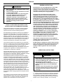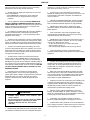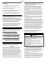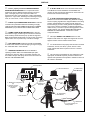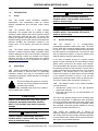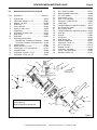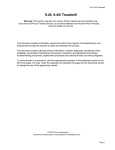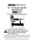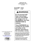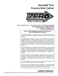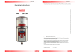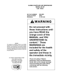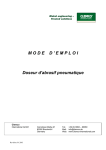
1
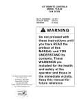
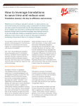
SENTINEL MEDIA METERING VALVE
O. M. 20951
MC FILE NUMBER: 1064-0193
DATE OF ISSUE:
04/93
REVISION:
F, 10/08
WARNING
© 2008 CLEMCO INDUSTRIES CORP.
One Cable Car Dr.
Washington, MO 63090
Phone (636) 239-4300
Fax (800) 726-7559
Email: [email protected]
www.clemcoindustries.com
Do not proceed with
these instructions until
you have READ the
orange cover of this
MANUAL and YOU
UNDERSTAND its
contents. * These
WARNINGS are
included for the health
and safety of the
operator and those in
the immediate vicinity.
*If you are using a Clemco Distributor
Maintenance and Part Guide, refer to
the orange warnings insert preceding
the Index before continuing with the
enclosed instructions.
Electronic files include a Preface
containing the same important
information as the orange cover.
PREFACE
GENERAL INSTRUCTIONS
WARNING
•
•
•
Described herein are some, BUT NOT ALL, of the major
requirements for safe and productive use of blast
machines, remote control systems, operator respirator
assemblies, and related accessories. Completely read ALL
instruction manuals prior to using equipment.
Read and follow ALL instructions before using
this equipment.
Failure to comply with ALL instructions can result
in serious injury or death.
In the event that the user, or any assistants of the
user of this equipment cannot read or cannot
completely understand the warnings and
information contained in these instructions, the
employer of the user and his assistants must
thoroughly educate and train them on the proper
operation and safety procedures of this
equipment.
The user's work environment may include certain
HAZARDS related to the abrasive blasting operation.
Proper protection for the blaster, as well as anyone else
that may be EXPOSED to the hazards generated by the
blasting process, is the responsibility of the user and/or
the employer. Operators MUST consult with their employer
about what hazards may be present in the work
environment including, but not limited to, exposure to dust
that may contain TOXIC MATERIALS due to the presence
of silica, cyanide, arsenic or other toxins in the abrasive,
or materials present in the surface to be blasted such as
lead or heavy metals in coatings. The environment may
also include fumes that may be present from adjacent
coatings application, contaminated water, engine exhaust,
chemicals, and asbestos. The work area may include
PHYSICAL HAZARDS such as an uneven work surface,
poor visibility, excess noise, and electrical hazards. The
operator MUST consult with his employer on the
identification of potential hazards, and the appropriate
measures that MUST be taken to protect the blaster and
others that might be exposed to these hazards.
NOTICE TO PURCHASERS AND USERS OF OUR
PRODUCTS AND THIS INFORMATIONAL MATERIAL
The products described in this material, and the information
relating to those products, is intended for knowledgeable,
experienced users of abrasive blasting equipment.
No representation is intended or made as to the suitability of
the products described herein for any particular purpose or
application. No representations are intended or made as to the
efficiency, production rate, or the useful life of the products
described herein. Any estimate regarding production rates or
production finishes are the responsibility of the user and must
be derived solely from the user’s experience and expertise,
and must not be based on information in this material.
ALL machines, components and accessories MUST be
installed, tested, operated and maintained only by trained,
knowledgeable, experienced users.
DO NOT modify or substitute any Clemco parts with other
types or brands of equipment. Unauthorized modification
and parts substitution on supplied air respirators is a
violation of OSHA regulations and voids the NIOSH
approval.
The products described in this material may be combined by
the user in a variety of ways for purposes determined solely by
the user. No representations are intended or made as to the
suitability or engineering balance of the combination of
products determined by the user in his selection, nor as to the
compliance with regulations or standard practice of such
combinations of components or products.
OPERATIONAL INSTRUCTIONS
Abrasive Blast Equipment is only a component of the range of
equipment used in an abrasive blasting job. Other products
may include an air compressor, abrasive, scaffolding, hydraulic
work platforms or booms, paint spray equipment,
dehumidification equipment, air filters and receivers, lights,
ventilation equipment, parts handling equipment, specialized
respirators, or equipment that while offered by Clemco may
have been supplied by others. Each manufacturer and supplier
of the other products used in the abrasive blasting job must be
contacted for information, training, instruction and warnings
with regard to the proper and safe use of their equipment in the
particular application for which the equipment is being used.
The information provided by Clemco is intended to provide
instruction only on Clemco products. All operators must be
trained in the proper, safe, use of this equipment. It is the
responsibility of the users to familiarize themselves with, and
comply with, all appropriate laws, regulations, and safe
practices that apply to the use of these products. Consult with
your employer about training programs and materials that are
available.
OPERATOR SAFETY EQUIPMENT
WARNING
•
•
•
Blast operators and others working in the vicinity of
abrasive blasting must always wear properlymaintained, NIOSH-approved, respiratory protection
appropriate for the job site hazards.
DO NOT USE abrasives containing more than one
percent crystalline (free) silica. Ref. NIOSH Alert
#92-102
Inhalation of toxic dust (crystalline silica, asbestos,
lead paint and other toxins) can lead to serious or
fatal disease (silicosis, asbestosis, lead or other
poisoning).
•
ALWAYS wear NIOSH-approved supplied-air respirators
as required by OSHA, in the presence of any dust including,
but not limited to, handling or loading abrasive; blasting or
working in the vicinity of blast jobs; and cleanup of expended
abrasive. Prior to removing respirator, an air monitoring
Our company is proud to provide a variety of products to the
abrasive blasting industry, and we have confidence that the
professionals in our industry will utilize their knowledge and
expertise in the safe efficient use of these products.
I
PREFACE
instrument should be used to determine when surrounding
atmosphere is clear of dust and safe to breathe.
equipment. If controls are altered, involuntary activation, which
may cause serious injury, can occur.
•
NIOSH-approved, supplied-air respirators are to be worn
ONLY in atmospheres:
• NOT IMMEDIATELY dangerous to life or health and,
• from which a user can escape WITHOUT using the
respirator.
•
Inspect the air control orifice DAILY for cleanliness.
NEVER use welding hose in place of twinline control hose. The
internal diameter and rubber composition are UNSAFE for
remote control use.
•
UNLESS OTHERWISE SPECIFIED, maximum working
pressure of blast machines and related components MUST
NOT exceed National Board approved 125 psig (8.5 BAR).
•
Clemco supplied-air respirators DO NOT REMOVE OR
PROTECT AGAINST CARBON MONOXIDE (CO) OR ANY
OTHER TOXIC GAS. Carbon monoxide and toxic gas removal
and/or monitoring device must be used in conjunction with
respirator to insure safe breathing air.
•
NEVER weld on blast machine. Welding may affect
dimensional integrity of steel wall and WILL VOID National
Board approval.
•
Air supplied to respirator MUST BE AT LEAST GRADE D
QUALITY as described in Compressed Gas Association
Commodity Specification G-7.1, and as specified by OSHA
Regulation 1910.139 (d).
•
Point nozzle ONLY at structure being blasted. High
velocity abrasive particles WILL inflict serious injury. Keep
unprotected workers OUT of blast area.
•
ALWAYS locate compressors to prevent contaminated air
(such as CO from engine exhaust) from entering the air intake
system. A suitable in-line air purifying sorbent bed and filter or
CO Monitor should be installed to assure breathing air quality.
•
NEVER attempt to manually move blast machine when it
contains abrasive. EMPTY machines, up to 6 cu. ft.(270kg)
capacity, are designed to be moved:
• on flat, smooth surfaces by AT LEAST two people;
• with the Clemco "Mule"; or
• with other specially designed machine moving devices.
•
ALWAYS use a NIOSH-approved breathing air hose to
connect an appropriate air filter to the respirator. Use of a nonapproved air hose can subject the operator to illness caused
by the release of chemical agents used in the manufacture of
non-approved breathing air hose.
•
Larger empty blast machines or ANY blast machine
containing abrasive MUST be transported by mechanical lifting
equipment.
•
ALWAYS check to make sure air filter and respirator
system hoses are NOT CONNECTED to in-plant lines that
contain nitrogen, acetylene or any other non-breathable gas.
NEVER use oxygen with air line respirators. NEVER modify air
line connections to accommodate air filter/respirator breathing
hose WITHOUT FIRST testing content of the air line. FAILURE
TO TEST THE AIR LINE MAY RESULT IN DEATH TO THE
RESPIRATOR USER.
AIR HOSE, BLAST HOSE, COUPLINGS, AND NOZZLE HOLDERS
•
Air hose, air hose fittings and connectors at compressors
and blast machines MUST be FOUR times the size of the
nozzle orifice. Air hose lengths MUST be kept as short as
possible AND in a straight line. Inspect DAILY and repair
leakage IMMEDIATELY.
•
Blast hose inside diameter MUST be THREE to FOUR
times the size of the nozzle orifice. AVOID sharp bends that
wear out hose rapidly. Use SHORTEST hose lengths possible
to reduce pressure loss. Check blast hose DAILY for soft
spots. Repair or replace IMMEDIATELY.
•
Respirator lenses are designed to protect against
rebounding abrasive. They do not protect against flying
objects, glare, liquids, radiation or high speed heavy materials.
Substitute lenses from sources other than the original
respirator manufacturer will void NIOSH-approval of this
respirator.
•
ALWAYS cut loose hose ends square when installing hose
couplings and nozzle holders to allow uniform fit of hose to
coupling shoulder. NEVER install couplings or nozzle holders
that DO NOT provide a TIGHT fit on hose. ALWAYS use
manufacturers recommended coupling screws.
BLAST MACHINES AND REMOTE CONTROLS
•
Replace coupling gaskets FREQUENTLY to prevent
leakage. Abrasive leakage can result in dangerous coupling
failure. ALL gaskets MUST be checked SEVERAL times during
a working day for wear, distortion and softness.
WARNING
•
•
ALWAYS equip abrasive blast machines with
remote controls.
Abrasive blast machine operators must wear NIOSHapproved supplied-air respirators (ref: OSHA
regulations 1910.94, 1910.132, 1910.139 and
1910.244).
•
Install safety pins at EVERY coupling connection to
prevent accidental disengagement during hose movement.
•
ALWAYS attach safety cables at ALL air hose AND blast
hose coupling connections. Cables relieve tension on hose and
control whipping action in the event of a coupling blow-out.
•
NEVER modify OR substitute remote control parts. Parts
from different manufacturers are NOT compatible with Clemco
II
PREFACE
MAINTENANCE
of the purchase price, as set forth below:
1. Seller makes no warranty with respect to products used
other than in accordance hereunder.
2. On products seller manufactures, seller warrants that all
products are to be free from defects in workmanship and
materials for a period of one year from date of shipment to
buyer, but no warranty is made that the products are fit for a
particular purpose.
3. On products which seller buys and resells pursuant to this
order, seller warrants that the products shall carry the then
standard warranties of the manufacturers thereof, a copy of
which shall be made available to customer upon request.
4. The use of any sample or model in connection with this
order is for illustrative purposes only and is not to be construed
as a warranty that the product will conform to the sample or
model.
5. Seller makes no warranty that the products are delivered
free of the rightful claim of any third party by way of patent
infringement or the like.
6. This warranty is conditioned upon seller’s receipt within ten
(10) days after a buyer’s discovery of a defect, of a written
notice stating in what specific material respects the product
failed to meet this warranty. If such notice is timely given, seller
will, at its option, either modify the product or part to correct the
defect, replace the product or part with complying products or
parts, or refund the amount paid for the defective product, any
one of which will constitute the sole liability of seller and a full
settlement of all claims. No allowance will be made for
alterations or repairs made by other than those authorized by
seller without the prior written consent of seller. Buyer shall
afford seller prompt and reasonable opportunity to inspect the
products for which any claim is made as above stated.
•
ALWAYS shut off compressor and depressurize blast
machine BEFORE doing ANY maintenance.
•
Always check and clean ALL filters, screens and alarm
systems when doing any maintenance.
•
ALWAYS cage springs BEFORE disassembling valves IF
spring-loaded abrasive control valves are used.
•
ALWAYS completely follow owner's manual instructions
and maintain equipment at RECOMMENDED intervals.
ADDITIONAL ASSISTANCE
•
Training and Educational Programs.
Clemco Industries Corp. offers a booklet, Blast-Off 2,
developed to educate personnel on abrasive blast equipment
function and surface preparation techniques. Readers will learn
safe and productive use of machines, components and various
accessories, including selection of abrasive materials for
specific surface profiles and degrees of cleanliness.
•
The Society for Protective Coatings (SSPC) offers a video
training series on protective coatings including one entitled
"Surface Preparation." For loan or purchase information,
contact SSPC at the address shown below.
TECHNICAL DATA AND RESEARCH COMMITTEES
•
The following associations offer information, materials and
videos relating to abrasive blasting and safe operating
practices.
The Society for Protective Coatings (SSPC)
40 24th Street, Pittsburgh PA 15222-4643
Phone: (412) 281-2331 • FAX (412) 281-9992
Email: [email protected] • Website: www.sspc.org
National Association of Corrosion Engineers (NACE)
1440 South Creek Drive, Houston TX 77084
Phone: (281) 228-6200 • FAX (281) 228-6300
Email: [email protected] • Website: www.nace.org
American Society for Testing and Materials (ASTM)
100 Barr Harbor Dr., West Conshohocken, PA 19428
Phone (610) 832-9500 • FAX (610) 832-9555
Email: [email protected] • Website: www.astm.org
Except as expressly set forth above, all warranties, express,
implied or statutory, including implied warranty of
merchantability, are hereby disclaimed.
DAILY SET-UP CHECK LIST
WARNING
•
•
•
•
NOTICE
•
This equipment is not intended to be used in an area that might
be considered a hazardous location as described in the
National Electric Code NFPA 70 1996, article 500.
•
WARRANTY
The following is in lieu of all warranties express, implied or
statutory and in no event shall seller or its agents, successors,
nominees or assignees, or either, be liable for special or
consequential damage arising out of a breach of warranty. This
warranty does not apply to any damage or defect resulting
from negligent or improper assembly or use of any item by the
buyer or its agent or from alteration or attempted repair by any
person other than an authorized agent of seller. All used,
repaired, modified or altered items are purchased “as is” and
with all faults. In no event shall seller be liable for
consequential or incidental damages. The sole and exclusive
remedy of buyer for breach of warranty by seller shall be repair
or replacement of defective parts or, at seller’s option, refund
ALL piping, fittings and hoses MUST be checked
DAILY for tightness and leakage.
ALL equipment and components MUST be thoroughly
checked for wear.
ALL worn or suspicious parts MUST be replaced.
ALL blast operators MUST be properly trained to
operate equipment.
ALL blast operators MUST be properly outfitted with
abrasive resistant clothing, safety shoes, leather gloves
and ear protection.
BEFORE blasting ALWAYS use the following check list.
□
1. PROPERLY MAINTAINED AIR COMPRESSOR sized
to provide sufficient volume (cfm) for nozzle and other tools
PLUS a 50% reserve to allow for nozzle wear. Use large
compressor outlet and large air hose (4 times the nozzle orifice
size). FOLLOW MANUFACTURERS MAINTENANCE
INSTRUCTIONS.
□
2. BREATHING AIR COMPRESSOR (oil-less air pump)
capable of providing Grade D Quality air located in a dust free,
contaminant free area. If oil-lubricated air compressor is used
to supply respirator, it should have high temperature monitor
and CO monitor or both. If CO monitor is not used, air MUST
be tested FREQUENTLY to ensure proper air quality.
III
PREFACE
□
□
3. Clean, properly maintained NIOSH-APPROVED
SUPPLIED-AIR RESPIRATOR. ALL components should
ALWAYS be present. NEVER operate without inner lens in
place. Thoroughly inspect ALL components DAILY for
cleanliness and wear. ANY substitution of parts voids NIOSH
approval i.e. cape, lenses, breathing hose, breathing air supply
hose, air control valve, cool air or climate control devices.
8. BLAST HOSE with ID 3 to 4 times the nozzle orifice.
Lines MUST be run AS STRAIGHT AS POSSIBLE from
machine to work area with NO sharp bends. Check DAILY for
internal wear and external damage.
□
9. HOSE COUPLINGS, NOZZLE HOLDERS fitted
SNUGLY to hose end and installed using PROPER coupling
screws. Coupling lugs MUST be snapped FIRMLY into locking
position. Gasket MUST form positive seal with safety pins
inserted through pin holes. Check gaskets and replace if ANY
sign of wear, softness or distortion. ALWAYS install safety
cables at every connection to prevent disengagement. Check
nozzle holder for worn threads. NEVER MIX DIFFERENT
BRANDS OF COMPONENTS. Check each of these
components DAILY.
□
4. OSHA required BREATHING AIR FILTER for removal
of moisture and particulate matter from breathing air supply.
THIS DEVICE DOES NOT REMOVE OR DETECT CARBON
MONOXIDE (CO). ALWAYS USE CO MONITOR ALARM.
□
5. ASME CODED BLAST MACHINE sized to hold 1/2
hour abrasive supply. ALWAYS ground machine to eliminate
static electricity hazard. Examine pop up valve for alignment.
Blast machine MUST be fitted with a screen to keep out foreign
objects and a cover to prevent entry of moisture overnight.
□
10. Inspect NOZZLE and GASKET DAILY for wear.
Replace nozzle when 1/16" larger than original size or if liner
appears cracked. Check nozzle threads for wear.
□
6. AIR LINE FILTER installed AS CLOSE AS POSSIBLE
to machine inlet. Sized to match inlet piping or larger air supply
line. Clean filter DAILY. Drain OFTEN.
□
11. Use abrasive that is properly sized and free of harmful
substances; such as, free silica, cyanide, arsenic or lead.
Check material data sheet for presence of toxic or harmful
substances.
□
7. REMOTE CONTROLS MUST be in PERFECT
operating condition. ONLY use APPROVED spare parts,
including twin- line hose. DAILY: test system operation and
check button bumper and spring action of lever and lever lock.
DO NOT USE WELDING HOSE.
□
12. Test surface to be blasted for toxic substances. Take
appropriate, and NIOSH required, protective measures for
operator and bystanders which pertain to substances found on
the surface to be blasted.
1 Air Compressor
11. Silica-free Abrasive
2. Breathing Air Compressor
(or)
2. Ambient Air Pump
for low pressure
respirator
5. ASME Coded
Blast Machine
7. Remote
Controls
3. NIOSH
Approved
Supplied-Air
Respirator
6. Air Line
Filter
10. Appropriately
Sized Nozzle
4. CPF Air-Filter
8. Blast Hose
9. Hose Couplings and
Safety Cables
IV
SENTINEL MEDIA METERING VALVE
1.0
INTRODUCTION
1.1
Scope
1.1.1 This manual covers installation, operation,
maintenance, and replacement parts for Clemco
Sentinel standard-use and fine-mesh media control
valves.
1.1.2 The Sentinel valve is a blast machine
component. The operator must be qualified to safely
operate the blast machine and remote controls, and all
other equipment used with the valve. To ensure safe
blasting, all operators and personnel involved with the
abrasive blasting process must read and understand the
manuals, including the information included in the
orange cover, for all devices used with the Sentinel
valve.
1.1.3 The Clemco booklet "Abrasive Blasting Safety
Practices" contains important safety information about
abrasive blasting that may not be included in equipment
operation manuals. Copies are available from Clemco
Industries and may be requested through our website
www.clemcoindustries.com or requested via email to
[email protected].
1.2
Safety Alerts
1.2.1 Clemco uses safety alert signal words, based on
ANSI Z535.4-1998, to alert the user of a potentially
hazardous situation that may be encountered while
operating this equipment. ANSI's definitions of the signal
words are as follows:
This is the safety alert symbol. It is used to
alert the user of this equipment of potential
personal injury hazards.
Obey all safety messages that follow this symbol to
avoid possible injury or death.
CAUTION
Caution used without the safety alert symbol
indicates a potentially hazardous situation
which, if not avoided, may result in property
damage.
CAUTION
Caution indicates a potentially hazardous
situation which, if not avoided, may result in
minor or moderate injury.
Page 1
WARNING
Warning indicates a potentially hazardous
situation which, if not avoided, could result in
death or serious injury.
DANGER
Danger indicates an imminently hazardous
situation which, if not avoided, will result in
death or serious injury.
1.3
General Description
1.3.1 The
Sentinel
is
a
normally-closed,
pneumatically-operated media control valve. The valve
can be used with a pressure-release system, as shown
in Figures 1 and 2, to stop the abrasive flow each time
the blast machine is depressurized. It can also be used
with a pressure-hold system, to stop the abrasive flow
while the machine remains under pressure.
If the valve is supplied as part of a Clemco remote
system, it will be controlled by a Clemco Abrasive Cutoff
Switch (ACS) mounted on the remote control handle.
This setup enables the operator to shut off the abrasive
flow, allowing air alone to exit the nozzle. This air flow is
used to clear abrasive from the blast hose, or for surface
blow-down. If the Sentinel valve is not used with a
Clemco ACS system, an ACS switch must be installed
on the Sentinel as shown in Figure 2. Use the ACS
instead of the metering handle to shut off abrasive flow.
The ACS is shown under accessories in Section 6.2.
1.3.2 The Sentinel comes in two models, standarduse and fine-mesh.
• Standard-use valves are for use with abrasives
coarser than 50-mesh.
• Fine-mesh valves are for use with abrasives 50mesh and finer.
The valves are identical except for the metering plate
and a few related parts. To identify the valve, look at the
end of the metering plate shaft. Fine-mesh valves have
a U stamped on the end; the shaft on standard valves
are unmarked. Conversion kits are available to convert
from one to the other. See Section 6.1.
1.3.3 Valves are available with or without an
inspection opening. Valves without inspection openings
are usually used only where height clearance (distance
from the bottom of the machine to the ground) is limited.
See Figure 3 for nominal dimensions.
© 2008 CLEMCO INDUSTRIES CORP. • www.clemcoindustries.com • Manual No. 20951
SENTINEL MEDIA METERING VALVE
Page 2
Sentinel valve installed on a blast machine
using pressure-release remote controls with ACS switch mounted on the control handle
Sentinel Valve
Twinline Hose
Twinline Hose
Single-line Hose
2.0
INSTALLATION
WARNING
Failure to observe the following procedures
before performing service on a blast machine
(pressure vessel) could cause serious injury or
death from the sudden release of trapped
compressed air.
• Depressurize the blast machine.
• Lockout and tagout the compressed air
supply.
• Bleed the air supply line to the blast
machine.
2.1
Remove abrasive from the blast machine,
depressurize the machine, and disconnect the
compressed air supply line.
2.2
Remove the existing abrasive metering valve
and necessary pipe fittings. NOTE: The following
installation describes how to install the valve on a
machine with minimal rotation clearance. It is not
RLX Control Handle w/
ACS Switch
ACS Switch
Figure 1
necessary to disassemble the valve if it rotates freely on
the bottom of the machine.
2.3
Remove the four cap screws holding the flanged
adaptor to the valve assembly.
2.4
Use a 1-1/2" close nipple to connect the flanged
adaptor to the outlet at the bottom of the blast machine.
If the adaptor has an inspection plate, position the plate
toward the blast hose connection. If the adaptor does
not have an inspection opening, align the bolt holes fore
and aft, with the wide gap toward the blast hose
connection.
2.5
Position the adaptor gasket between the flanged
adaptor and valve assembly, and bolt the parts together.
2.6
Connect pipe fittings between the wye and
existing pusher line. It may be necessary to "fit" with new
nipples to align the height of the pusher line with the
wye.
2.7
Attach the quick coupling and nipple to the wye.
© 2008 CLEMCO INDUSTRIES CORP. • www.clemcoindustries.com • Manual No. 20951
SENTINEL MEDIA METERING VALVE
2.8
Control Hose Connections
2.8.1 If a Clemco remote control with ACS control
handle is used, connect the “single” control line to the
fitting on the upper body as shown in Figure 1. Refer to
the blast machine and remote control manuals for set-up
and operation of the particular equipment.
2.8.2 If other machines or control systems are used,
the valve should be ordered with the ACS. Note: the
ACS switch and fittings are shown under accessories in
Section 6.2. Refer to Figures 2 and 5 while making the
following changes:
Install a tee for the
ACS switch before
the inlet valve.
Air flow
Air supply hose to
the cut-off switch, is
supplied by the
user.
Page 3
2.8.2.2 Screw the 1/8" hex nipple provided, into the
"CYL" port of the ACS switch, and attach it to the upper
body.
2.8.2.3 Install the fitting removed in the previous step,
(or one that is compatible with the system used), into the
"IN" port of the ACS switch.
2.8.2.4 If the Sentinel is installed on a manuallyoperated blast machine, such as in an automated
system, connect an air line between the "IN" port fitting
and a tee installed before the machine’s air-inlet valve.
Refer to the top illustration in Figure 2.
2.8.2.5 If the Sentinel is connected to a remote system,
connect the air line from the "IN" port fitting to a
controlled air line (one that is on the controlled side of
the remote control air line, which will pressurize when
the control handle is pressed). One method is to tee off
the inlet or outlet valves of the remote system. Doing so
closes the valve when the remote controls depressurize
the blast machine, resulting in a smoother start when the
machine is re-pressurized. Refer to the bottom
illustration in Figure 2.
ACS cut-off switch
Flange Adaptor without
Inspection opening
Connection with manually-operated machine
Air supply hose to the
cut-off switch is
supplied by the user.
Flange Adaptor with
Inspection opening
This line must be tied
into the remote controls,
controlled-air circuit.
Connection with remote-controlled machine
Figure 2
Figure 3
2.8.2.1 Remove the fitting on the upper body cylinder
port.
2.8.2.6 If a pressure regulator is used, control air for the
Sentinel should be sourced up-stream of the regulator.
Doing so allows full line pressure to control the valve
© 2008 CLEMCO INDUSTRIES CORP. • www.clemcoindustries.com • Manual No. 20951
SENTINEL MEDIA METERING VALVE
while blasting pressure can be adjusted down to
approximately 30 psi. The Sentinel valve requires control
line pressure to be between 65 psi and 150 psi.
WARNING
Excessive compressed air pressure could
cause a blast machine to rupture. To prevent
serious injury or death, do not exceed the rated
pressure of the blast machine vessel.
Page 4
NOTE: The ACS performs dual functions: Use it to clear
abrasive from the blast hose and to blow off abrasive
from the blasted surface at the blasting area. Small
amounts of abrasive may exit the nozzle with the air.
Residual abrasive may remain on the surface, and have
to be removed outside the blast area prior to painting.
4.0
MAINTENANCE
WARNING
3.0
OPERATION
3.1
When the valve is correctly installed, it opens
and closes pneumatically as control-air is applied or
removed from the valves actuating piston. If the valve is
used in conjunction with the remote control system, it
opens when the remote controls begin the blasting
process, and closes when the controls stop the blasting
process. If the valve is used independently of remote
controls, it opens and closes with the use of the ACS
switch.
3.2
Abrasive Metering: Abrasive will not flow
through the valve unless it is open (see Paragraph 3.1)
Abrasive flow is adjusted at the metering handle. The
valve is closed when the handle is fully right. To adjust,
close the valve and slowly move the handle to the left to
increase flow. Use as little abrasive as possible while
maintaining the best cleaning rate. Generally, with the
correct mixture, abrasive can be seen as light
discoloration as it exits the nozzle. The valve is fully
open when the handle is fully left.
3.3
Operation of the Abrasive Cut-Off Switch.
3.3.1 The ACS switch is “OFF” (no abrasive) when the
toggle is pointing forward toward the nozzle ("EXH" port)
or down if installed on the Sentinel valve as shown in
Figure 2. Abrasive flow is “ON” when the toggle is
pointing backward away from the nozzle ("CYL" port) (up
if it is as shown in Figure 2).
3.3.2 By moving the switch to the “OFF” position, the
air supply to the Sentinel valve is shut-off and vented
through the exhaust port. The Sentinel then closes and
abrasive flow stops. This allows the operator to have air
alone coming from the nozzle, which can be used to
clear the blast hose before shut-down, and to blow
abrasive off the blasted surface. The switch can be
opened or closed any time, but will not activate the
metering valve unless the control handle is pressed.
Failure to observe the following procedures
before performing any maintenance on a blast
machine could cause serious injury from the
sudden release of trapped compressed air.
• Depressurize the blast machine.
• Lockout and tagout the compressed air
supply.
• Bleed the air supply line to the blast
machine.
NOTE: The easiest way to service the valve is to remove
it from the blast machine. The easiest way to remove the
valve is to remove the four bolts holding the flanged
adaptor to the valve assembly and disconnecting the
pusher line. The valve and lower piping can then be
removed as an assembly. The flanged adaptor remains
on the machine, but it should be inspected and replaced
it worn.
4.1
Removing Upper Body Assembly (shut-off
section).
4.1.1 Remove nuts and cap screws holding the upper
body onto the flanged adaptor.
4.1.2 Attach an air line to the fitting on the cylinder
port on the upper body assembly, and pressurize the
line to retract the shut-off piston. NOTE: If air is not
available, use care when removing the bolts per Section
4.1.3.
4.1.3 Remove the control handle, gauge unit studs,
and the four bolts holding the upper body assembly to
the lower assembly. (Note: If the piston was not
retracted per Section 4.1.2., loosen the nuts in
sequence. Once the nuts are loose, the lower body will
be forced away from the upper body by approximately
1/2".)
4.1.4 Remove the upper body assembly. NOTE: The
seat, seat plate, and seat plate gaskets will be loose; do
not misplace them.
© 2008 CLEMCO INDUSTRIES CORP. • www.clemcoindustries.com • Manual No. 20951
SENTINEL MEDIA METERING VALVE
4.1.5 Depressurize the air line to the upper body
cylinder port.
4.2
4.3.7 Inspect all parts. Replace any that are worn or
damaged.
Inspection of Upper Body Assembly
4.4
4.2.1 Remove the six cylinder cap screws and then
remove the cap and cap gasket.
4.2.2 Using a 9/16" socket (with impact wrench if
available), remove the cap screw from inside the
cylinder. The cap screw holds the piston cup to the shutoff piston, and compresses the piston against the spring.
As the screw is removed, the spring will decompress,
forcing the shut-off piston out of the body assembly.
4.2.3
Remove the shut-off piston and spring.
4.2.4
Remove the wear sleeve.
4.2.5 Remove both u-seals from inside the wear
sleeve.
4.2.6 Remove the piston cup by inserting a long 3/8"
socket extension, screw driver or similar object through
the cup hole and pry upward.
4.2.7 Remove the o-rings from the upper body, one is
in the piston stem guide hole, the other is in the wear
sleeve cavity.
4.2.8 Inspect all items, including the seat, seat plate
and seat plate gaskets. Replace any worn or damaged
parts.
4.3
Page 5
Reassembly of Upper Body
4.4.1 Place new o-rings into the groove in the piston
stem guide hole and wear sleeve cavity. The o-rings
must be completely seated into the grooves.
4.4.2 Lubricate the edge of the piston cup, inside of
the cylinder cavity, and o-rings with lightweight oil or light
silicone grease.
4.4.3 Insert the piston cup into the cylinder. Do not
allow the rubber lip of the cup to curl. Use a dull edge to
work the lip into the opening. Once the cup is inserted,
push it to the bottom of the cylinder.
4.4.4
Place the spring into the upper valve body.
4.4.5 Insert the shut-off piston, stem first through the
guide hole until it bottoms against the spring.
4.4.6 Put new u-seals in the wear sleeve as shown in
Figure 4. The seal closest to the flange goes in first, with
the seal expansion ring facing the flange. The second useal is placed next to the first with the ring also facing
the flange.
Wear Sleeve
U-Seal
Inspection of Lower Body Assembly.
4.3.1 Inspect the lower body assembly for wear or
damage. If service is required, use the following
instructions to disassemble.
Expansion Ring
4.3.2 Lay the valve assembly on a flat service, and
push down on the handle to remove the handle pin,
handle, and spring.
4.3.3 Push the metering plate and stem assembly
through the body.
4.3.4 Remove the shaft gasket from the metering
plate stem.
4.3.5 Remove the packing gland from the body, by
prying up on the flange or pushing from the bottom.
4.3.6 Remove the o-rings from the lower body and
packing gland.
Flange
Alignment Hole
Figure 4
4.4.7 Place the wear sleeve in the body. Align the
hole in the sleeves flange with the pin in the body. Make
sure the opening in the wear sleeve lines up with the
opening in the body.
4.4.8 Working from the piston side, place the flat
washer and rubber-backed washer on the piston cup
cap screw (rubber on rubber washer against the piston
cup). Push the screw through the hole in the cup and
screw it into the shut-off piston shaft. As the cap screw is
© 2008 CLEMCO INDUSTRIES CORP. • www.clemcoindustries.com • Manual No. 20951
SENTINEL MEDIA METERING VALVE
Page 6
tightened, it will compress the spring and draw the shutoff piston and shaft into place. An impact wrench works
best for tightening the piston screw. If a hand wrench is
used, it may be necessary to grip the shut-off piston with
pliers as the screw is tightened.
4.6.6 Put the lower body assembly in place and bolt
the upper and lower body assemblies together using the
four bolts (do not put the studs in at this time). Handtighten all nuts before tightening them in sequence to
uniformly compress the bodies together.
4.4.9 Recheck the alignment of the wear sleeve pin
hole. When the hole is aligned, lay a large socket or
similar object on the wear sleeve, and tap it until the
sleeve is fully seated into the body.
4.6.7
4.5
4.6.9
Reassembly of Lower Body
4.5.1 Place new o-rings in the lower body and packing
gland. Lubricate both o-rings.
Depressurize and remove the cylinder air line.
4.6.8 Remove the handle, and install the studs and
gauge unit assembly. When the gauge unit is in place
and studs are tightened, re-install the handle.
Bolt the cylinder cap and gasket in place.
4.6.10 Bolt the flanged adaptor and flange gasket onto
the body assembly.
4.5.2 Push the packing gland into the lower body until
it bottoms-out on the flange.
4.5.3 Place a new shaft gasket over the metering
plate stem, and push the stem through the packing
gland. Hold the gland in place as the shaft is pushed
through.
4.5.4 Put the spring and handle on the stem, position
the handle so it points away from the metering plate.
4.5.5 Push on the handle and tap around the top to
compress the spring until the handle clears the hole on
the stem.
4.5.6 Push the handle pin through the stem to lock the
handle in place.
4.5.7 Make sure the handle and metering plate are at
180 degrees.
4.6
Reassembly of Upper and Lower Valve
Assemblies.
4.6.1 Apply air to the upper body cylinder to retract
the shut-off piston. Set the cylinder end of the upper
body on a flat surface. The seat plate flange should be
facing up.
4.6.2 Place the rubber seat (the beveled side must
face the shut-off piston) into the wear sleeve recess.
4.6.3 Set a seat plate gasket on the upper body seat
plate flange.
4.6.4 Place the seat plate on top of the gasket. The
two sealing ridges must face toward the rubber seat.
4.6.5
5.0
TROUBLESHOOTING
5.1
No abrasive flow
5.1.1 Metering valve closed. Closed is when the
metering handle is fully right.
5.1.2 ACS switch is closed. Switch is closed when the
toggle is pointed toward the "EXH" port.
5.1.3 Leak or blockage in the air hose or fittings
between the control unit and the Sentinel valve.
5.1.4
Machine empty.
5.1.5 Abrasive or foreign material jamming the valve’s
shut-off piston, wear sleeve, spring, or piston cup. Check
seals and o-rings.
5.1.6 Cap screw securing piston cup is loose or
broken.
5.1.7
Relief hole in cylinder cap is plugged.
5.1.8 Leaks around seat plate gaskets, or flanged
adaptor gasket.
5.1.9
Obstruction in media valve. Clear as follows:
5.1.9.1 Fully open the media control valve, (Fully open
is when the metering handle is fully left). While blasting,
close the choke valve to force out small obstructions or
wet abrasive.
Set another plate gasket on the seat plate.
© 2008 CLEMCO INDUSTRIES CORP. • www.clemcoindustries.com • Manual No. 20951
SENTINEL MEDIA METERING VALVE
WARNING
To avoid serious injury or death, depressurize
the blast machine, lockout and tagout the
compressed air supply before continuing.
5.1.9.2 For larger obstructions, shut the machine down
to examine the abrasive valve. Remove the inspection
plate from the flanged adaptor and clear obstruction.
5.6.2 Abrasive bridging in the blast machine. This is
usually caused by using very fine abrasive, or by moist
air. See Section 4.1.
6.0
ACCESSORIES and REPLACEMENT PARTS
6.1
Conversion Kits
Converts fine-mesh valve to standard-use ............ 22848
Converts standard-use valve to fine-mesh ............ 22849
WARNING
Do not stick fingers into the piston area of the
inspection opening. The piston is under spring
pressure, and could suddenly close when the
obstruction is cleared.
6.2
Accessories for Use with
Remote Control Applications, Figure 5
Item
5.2
Abrasive flow does not stop when ACS
switch is turned off.
1.
5.2.1 Control air is not exhausting from the switch.
Check the exhaust muffler for blockage and check the
control handle per the control handle manual.
2.
3.
4.
5.
6.
5.2.2
Worn valve seat.
5.2.3
Worn shut-off piston.
5.2.4
5.1.9.
Obstruction on the valve seat. See Section
5.3
Metering handle will not move.
5.4
Air leaks through relief hole in cylinder cap.
5.4.1
Worn piston cup.
5.5
Air leaks through relief hole in valve body
(spring chamber).
5.5.1 Worn u-seals in wear sleeve, or worn o-ring
between the valve body and wear sleeve.
flow
decreases
shortly
after
Non-Clemco
Description .............................................Stock No.
Adaptor, straight
1/8" NPT ............................................. 01940
1/4” NPT ............................................. 02494
Adaptor, elbow
1/8" NPT ............................................. 02827
1/4” NPT ............................................. 02513
Connector, 1/8" brass ............................. 01962
Breather muffler, 1/8" .............................. 07657
Valve, 3-way, ACS switch ........................ 07658
Hose, 3/16” coupled
3-foot length ....................................... 02498
5-foot length ....................................... 03083
2
1
5.3.1 Damp or hardened abrasive packed around
metering plate. Disassemble valve to clean.
5.6
Abrasive
blasting starts.
Page 7
6
Item 5 may be remotely
mounted using a hose
between it and the
Sentinel valve
3
5
1
4
5.6.1 Insufficient air supply causing control pressure
to drop, in turn closing the valve. Check for undersized
air supply hose, and the CFM of compressor against the
cfm consumption of the nozzle.
© 2008 CLEMCO INDUSTRIES CORP. • www.clemcoindustries.com • Manual No. 20951
Figure 5
SENTINEL MEDIA METERING VALVE
(-)
6.3
Replacement Valves
(-)
Sentinel valve with attached ACS, standard-use
for abrasives coarser than 50-mesh,
with inspection plate ...........................20508
without inspection opening .................20509
Page 8
Service kit, lower segment, Figure 7..........22389
22389 LOWER-SEGMENT
SERVICE KIT
Item Qty. Description
(-)
Sentinel valve, w/o attached ACS, standard-use
for abrasives coarser than 50-mesh,
with inspection plate ............................20608
without inspection opening ..................20609
(-)
Sentinel valve w/o attached ACS, fine-mesh
for abrasives 50-mesh and finer
with inspection plate ............................21439
6.4
Service Kits
(-)
Service kit, upper segment, Figure 6 ........22388
1.
2.
3.
4.
1
2
1
2
5.
6.
1
1
22388 UPPER-SEGMENT
SERVICE KIT
Seat, rubber
Gasket, seat plate
O-ring, gland, 5/8” ID nom.
Gasket, shaft
(One is for standard-use [coarse media]
has a 1-3/8” nominal OD)
(One is for a urethane plate [fine-mesh]
has a 1” nominal OD)
O-ring, lower body 1” ID
O-ring, Inspection plate, 1-3/4” OD nom.
6
Item Qty. Description
1.
2.
3.
4.
5.
6.
7.
8.
9.
10.
11.
1
1
1
2
1
1
1
1
2
1
1
Washer, rubber backed
O-ring, piston shaft bore, 3/4” ID nom.
Gasket, cylinder cap
U-seal
O-ring, inspection plate 1-3/4” OD nom.
Gasket, flanged adaptor
Roll pin, 1/16” x 1/2”
O-ring, Main body, 2-1/4” nom.
Gasket, seat plate
Cap screw, 3/8-NC x 2"
Washer, 5/16" flat
2
2
4
5
1
Figure 7
5
3
10, 11, 1
6
2
3
9
9
4
8
7
Figure 6
© 2008 CLEMCO INDUSTRIES CORP. • www.clemcoindustries.com • Manual No. 20951
SENTINEL MEDIA METERING VALVE
6.5
Sentinel Replacement Parts, Figure 8
Item
Description............................................Stock No.
1.
2.
3.
4.
5.
6.
7.
8.
9.
10.
11.
Cylinder cap .............................................. 20512
Cap screw, 3/8-NC x 1-1/2" ...................... 03267
Adaptor, 1/8" NPT ..................................... 01940
Piston cup ................................................. 20515
Piston, shut-off .......................................... 20494
Spring, 2" OD x 4-1/2" .............................. 20600
Upper body ............................................... 20514
Cap screw, 5/16-NC x 3/4" ....................... 03151
Wear sleeve .............................................. 20495
Seat plate .................................................. 20497
Metering plate and stem
Standard-use, coarser than 50-mesh .... 20499
Fine-mesh, Urethane, 50-mesh & finer . 21438
Packing gland ........................................... 21021
Spring, 5/8" ID x 1-11/16" ......................... 01982
Close nipple, 1-1/2" schedule 80............... 01791
Inspection plate ........................................ 02440
Cap screw, 5/16-NC x 1-1/4" .................... 19509
Cap screw, 1/2-NC x 2-1/2" ...................... 03457
12.
13.
14.
15.
16.
17.
18.
19.
20.
21.
22.
23.
24.
25.
26.
27.
28.
29.
30.
31.
32.
33.
34.
35.
36.
37.
38.
39.
Page 9
Nut, 1/2-NC hex head ............................... 03511
Metering handle, heavy duty .................... 20498
Pin, valve handle ...................................... 20246
Close nipple, 1-1/4" .................................. 01717
Wye, 1-1/4" standard ................................ 01818
Set screw, 1/4-NC SQ. HD. ...................... 03080
Lower body ............................................... 20511
Flanged adaptor w/ inspection opening ... 20513
Nut, 3/8-NC hex head ............................... 03311
Nut, 5/16-NC wing .................................... 03213
Flanged adaptor w/o inspection opening . 20522
Hitch pin..................................................... 20245
Petcock ...................................................... 01993
Gauge unit ................................................ 02433
Stud, gauge unit ....................................... 02436
Spacer, handle bolt ................................... 02431
Cap screw, 1/4-NC x 1" ............................ 03053
Nut, 1/4-NC wing ...................................... 03113
Washer, 1/4 flat ........................................ 03116
Connector, 1/8” brass ............................... 01962
Valve, 3-way ACS switch........................... 07658
Breather, muffler 1/8” ................................ 07657
14
25
16
15
8
27
7
1
28
2
26
37
4
17
38
3
30
6
3
39
5
13
18
9
19
11
12
10
24
Items not called out are available in
service kits only.
Refer to Page 8 for service kits.
20
35
21
36
22
29
33
32
34
31
23
Figure 8
© 2008 CLEMCO INDUSTRIES CORP. • www.clemcoindustries.com • Manual No. 20951