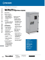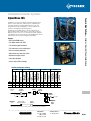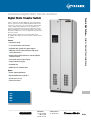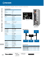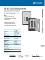
1
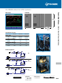
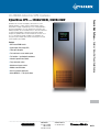
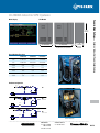
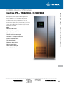
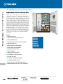
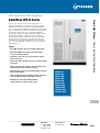
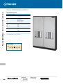
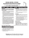
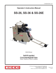
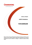
In this section...
Cyberex
Industrial
Power
Conditioning
®
Cyberex® Industrial Power Conditioning
UL®/NEMA Industrial UPS Systems.............................. H-568–H-582
IEC Industrial UPS Systems......................................... H-583–H-585
Float Battery Chargers................................................ H-586–H-590
Standalone Inverter Systems...................................... H-591–H-592
Standalone Digital Static Transfer Switches................ H-593–H-594
Power Distribution Systems........................................ H-595–H-596
UL /NEMA Industrial UPS Systems
CyberWave UPS — 10kVA/8kW, 15kVA/12kW, 20kVA/16kW
Power & High Voltage — Cyberex ® Industrial Power Conditioning
®
CyberWave UPS, the world’s first digitally controlled UPS for custom
industrial applications, combines Cyberex’s hallmark rugged electrical
design with the versatility of digital signal processors, field-programmable
gate arrays and EPROMs to set a new standard in UPS performance
and reliability. CyberWave UPS has standard features no other UPS
manufacturer can match, including Modbus communications, advanced
battery management capabilities and the world’s first VGA, full-color touch
screen 8" x 11" control panel (PowerPad). In addition, every CyberWave UPS
incorporates Cyberex’s Digital Static Transfer Switch design for increased
system redundancy and reliability.
Features
• IGBT-based PWM inverter
• Digital Signal Processing (DSP)
• Fiber optic datapaths
• Full-color touch screen monitor panel
• Full isolation – input/output transformers
• Industrial-grade frame/cabinet
• Fully rated static switch
• Maintenance bypass switch
• Modbus communications
• RS-232 communications port
• Meets NEMA/UL® 1778 standard
H-568
United States
Tel: 901.252.8000
800.816.7809
Fax: 901.252.1354
Technical Services
Tel: 888.862.3289
www.tnb.com
UL /NEMA Industrial UPS Systems
®
77.25" H
(1962mm)
37" W (940mm)
M1, M2
60.25" W (1530mm)
M3
34.4" D
(873mm)
Side View
Circuit Breakers/Fuse Sizes
10kVA/8kW
CB 201 – AF/AT
208V
125AF/80AT
480V
125AF/35AT
F 101, 201, 202 – Rating (A)
120VDC
150A
240VDC
80A
CB 102, 154, 159 – Rating (AF)
120VAC
125A
CB 202, 203, 101 – Rating (AF)
120VDC
125A
15kVA/12kW
20kVA/16kW
125AF/125AT
125AF/50AT
150AF/250AT
125AF/80AT
250A
125A
300A
150A
250A
250A
250A
250A
Power & High Voltage — Cyberex ® Industrial Power Conditioning
UPS Module
Mimic Display
Hardware Configuration
CB201
F201
F101
Inverter
M1
F202
CB202
Optional
CB201
F201
CB159
F101
F202
M2
Add CB 154 & 159
CB202
CB154
Optional
CB201
CB203
F201
CB101
CB102
F101
F202
CB202
CB159
M3
Add CB 101, 203, 102
CB154
Isolation Transformer
Optional
www.tnb.com
United States
Tel: 901.252.8000
800.816.7809
Fax: 901.252.1354
Technical Services
Tel: 888.862.3289
H-569
UL /NEMA Industrial UPS Systems
Power & High Voltage — Cyberex ® Industrial Power Conditioning
®
H-570
Product Specifications
AC Input
Input Voltage
Metering
Three Options: PowerPad 1, PowerPad 2 and PowerPad 3
480VAC, 3W+G
208VAC, 3W+G
Metering Value (1% Accurate)
Max. Input Current @ Rated Load
(Nominal VAC)
(10kVA/8kW)
21A @ 480VAC–49A @ 208VAC
(15kVA/12kW)
32A @ 480VAC–74A @ 208VAC
(20kVA/16kW)
43A @ 480VAC–99A @ 208VAC
Input Voltage Range
+10, -20% VAC from Nominal
Input Power Factor
.75 @ Full Load and Nominal
Current Walk-In
Up to Full Load in 15 Seconds
Surge Withstand
Meets IEEE 587/ANSI C62.41
Input Current THD%
30% Typical,
10% with Optional Input Filter
DC Bus/Battery
DC Voltage (Nominal)
120VDC (60 Cells Nominal)
240VDC (120 Cells Nominal)
DC Range
105–140VDC–210–280VDC
DC Regulation
±.25% from 0 to 100% Load
DC Ripple
< 2% RMS Ripple @ 100% Load
with Battery Connected
DC-AC Efficiency
88% (Typical)
DC End Volts
1.75V/Cell End Volts
Environmental
Acoustical Noise Level
< 60 dBA @ 3 Feet
Operating Temperature
0–40° C
Relative Humidity
0–95% Non-Condensing
Access
No Rear or Side Access Required
for Operations or Maintenance
AC Efficiency
Typical 83% (kW out/kW in)
Cooling
Forced Air (in front/out top)
Heat Rejection
(10 kVA/8 kW)
4200 BTU/hr.
(15 kVA/16 kW)
5600 BTU/hr.
(20 kVA/16 kW)
7460 BTU/hr.
Operating Altitude
Up to 1000m w/o Derating Load
AC Output
Output Voltage
120V (other voltages available; contact factory)
Output Current (Nominal)
(10kVA/8kW)
83A @ 120VAC
(15kVA/16kW)
125A @ 120VAC
(20kVA/16kW)
167A @ 120VAC
Voltage Regulation
<±.5% Steady State for
0 to 100% Load Change
Transient Response
<± 5% for a 100% Load Step
<± 1% for a Loss/Return AC Input Power
<± 5% for Manual Transfer to
Bypass and Back, 100% Load
<± 5% for a 100% Load Step
Recovery
Return to within ± 2.5% of
Nominal within 16 msec
Voltage Distortion
Linear Loads: <± 3.5% @ 100% Load
Overload
Up to 150% for 15 Min.
Overload Static Bypass
>1000% for 1 Cycle
Frequency
60 Hz (50 Hz Optional)
Frequency Stability
±.1% Free Running
Frequency Slew Rate
1.0 Hz/Sec. Maximum
Weight
M1, M2
1,600 lb. (726 kg)
M3
2,100 lb. (953 kg)
United States
Tel: 901.252.8000
800.816.7809
Fax: 901.252.1354
Metering Features
Input Voltage (All Phase)
Input Current (All Phase)
Input Frequency
Output Voltage (VDC)
Output Current
Battery
Voltage (VDC)
Current
Runtime
Time Remaining
Power
Cycles
Total Cycles
Test Cycles
Inverter Voltage (RMS)
Current (RMS)
Frequency
Input Voltage (VDC)
Output
Voltage (RMS)
Current (RMS)
Frequency
Real Power (W)
Apparent Power (VA)
% Loading
Crest Factor
Peak Current
Power Factor
Alternate Input Voltage
Line
Input Frequency
Rectifier
PowerPad 1
PowerPad 2
PowerPad 3
✔
✔
✔
✔
✔
✔
✔
✔
✔
✔
✔
✔
✔
✔
✔
✔
✔
✔
✔
✔
✔
✔
✔
✔
✔
✔
✔
✔
✔
✔
✔
Optional
Optional
Optional
✔
✔
✔
✔
✔
✔
✔
✔
✔
✔
✔
✔
✔
✔
✔
✔
✔
✔
✔
✔
✔
✔
✔
✔
✔
✔
To order the CyberWave UPS, please contact your T&B sales representative.
Technical Services
Tel: 888.862.3289
www.tnb.com
UL /NEMA Industrial UPS Systems
CyberWave UPS — 25kVA/20kW, 30kVA/24kW
®
Features
• IGBT-based PWM inverter
• Digital Signal Processing (DSP)
• Fiber optic datapaths
• Full-color touch screen monitor panel
• Full isolation – input/output transformers
• Industrial-grade frame/cabinet
• Fully rated static switch
• Maintenance bypass switch
• Modbus communications
• RS-232 communications port
Power & High Voltage — Cyberex ® Industrial Power Conditioning
CyberWave UPS, the world’s first digitally controlled UPS for custom
industrial applications, combines Cyberex’s hallmark rugged electrical
design with the versatility of digital signal processors, field-programmable
gate arrays and EPROMs to set a new standard in UPS performance and
reliability. CyberWave UPS has standard features no other UPS manufacturer
can match, including Modbus communications and advanced battery
management capabilities and the world’s first VGA, full-color touch screen
8" x 11" control panel (PowerPad). In addition, every CyberWave UPS
incorporates Cyberex’s Digital Static Transfer Switch design for increased
system redundancy and reliability.
• Meets NEMA/UL® 1778 specifications
www.tnb.com
United States
Tel: 901.252.8000
800.816.7809
Fax: 901.252.1354
Technical Services
Tel: 888.862.3289
H-571
UL /NEMA Industrial UPS Systems
Power & High Voltage — Cyberex ® Industrial Power Conditioning
®
Circuit Breakers/Fuse Sizes
Mimic Display
25kVA/20kW
CB 201 – AF/AT
208V
250 AF/200 AT
480V
125 AF/80 AT
F 101, 201, 202 – Rating (A)
120VDC
400A
240VDC
200A
CB 102, 154, 159 – Rating (AF)
120VAC
400A
CB 202, 203, 101 – Rating (AF)
120VDC
400A
30kVA/24kW
225 AF/250 AT
125 AF/90 AT
500A
250A
400A
400A
Hardware Configuration
UPS Module
CB201
F201
F101
M1
F202
CB202
Optional
CB201
F201
CB159
F101
F202
M2
Add CB 154 & 159
CB202
CB154
Optional
CB201
CB203
F201
37" W (940mm)
60.25" W (1530mm)
M1
M2
M3 (Not shown), 74" W (1880mm)
CB101
CB102
F101
F202
CB202
CB159
M3
Add CB 101, 203, 102
CB154
Optional
77.25" H
(1962mm)
34.4" D
(873mm)
Side View
H-572
Inverter
United States
Tel: 901.252.8000
800.816.7809
Fax: 901.252.1354
Technical Services
Tel: 888.862.3289
Isolation Transformer
www.tnb.com
UL /NEMA Industrial UPS Systems
®
Metering
AC Input
Input Voltage
Three Options: PowerPad 1, PowerPad 2 and PowerPad 3
Metering Value (1% Accurate)
480VAC, 3W+G
208VAC, 3W+G
Max. Input Current @ Rated Load (Nominal VAC)
(25kVA/20kW)
53A @ 480VAC–123A @ 208VAC
(30kVA/24kW)
43A @ 480VAC–148A @ 208VAC
Input Voltage Range
+10, -20% VAC from Nominal
Input Power Factor
.75 @ Full Load and Nominal
Current Walk-In
Up to Full Load in 15 Seconds
Surge Withstand
Meets IEEE 587/ANSI C62.41
Input Current THD%
30% Typical,
10% with Optional Input Filter
DC Bus/Battery
DC Voltage (Nominal)
120VDC (60 Cells Nominal)
240VDC (120 Cells Nominal)
DC Range
105–140VDC–210–280VDC
DC Regulation
±.25% from 0 to 100% Load
DC Ripple
< 2% RMS Ripple @ 100% Load
with Battery Connected
DC-AC Efficiency
88% (Typical)
DC End Volts
1.75V/Cell End Volts
Environmental
Acoustical Noise Level
< 60 dBA @ 3 Feet
Operating Temperature
0–40° C
Relative Humidity
0–95% Non-Condensing
Access
No Rear or Side Access Required
for Operations or Maintenance
AC Efficiency
Typical 83% (kW out/kW in)
Cooling
Forced Air (in front/out top)
Heat Rejection
(25kVA/20kW)
12,050 BTU/hr.
(30kVA/24kW)
19,320 BTU/hr.
Operating Altitude
Up to 1000m without Derating Load
AC Output
Output Voltage
120V (other voltages available; contact factory)
Output Current (Nominal)
(25kVA/20kW)
208A @ 120VAC
(30kVA/24kW)
250A @ 120VAC
Voltage Regulation
<±.5% Steady State for
0 to 100% Load Change
Transient Response
<± 5% for a 100% Load Step
<± 1% for a Loss/Return AC Input Power
<± 5% for Manual Transfer to
Bypass and Back, 100% Load
<± 5% for a 100% Load Step
Recovery
Return to within ± 2.5% of
Nominal within 16 msec
Voltage Distortion
Linear Loads: <± 3.5% @ 100% Load
Overload
Up to 150% for 15 Min.
Overload Static Bypass
>1000% for 1 Cycle
Frequency
60 Hz (50 Hz Optional)
Frequency Stability
±.1% Free Running
Frequency Slew Rate
1.0 Hz/Sec. Maximum
Weight
25kVA
30kVA
M1
2,300 lb. (1,043kg)
2,590 lb. (1,175kg)
M2
2,560 lb. (1,161kg)
2,850 lb. (1,293kg)
M3
2,620 lb. (1,188kg)
2,910 lb. (1,320kg)
www.tnb.com
Rectifier
Battery
Inverter
Output
Alternate
Line
United States
Tel: 901.252.8000
800.816.7809
Fax: 901.252.1354
Metering Features
PowerPad 1
Input Voltage (All Phase)
✔
Input Current (All Phase)
✔
Input Frequency
Output Voltage (VDC)
Output Current
Voltage (VDC)
✔
Current
✔
Runtime
Time Remaining
Power
Cycles
Total Cycles
Test Cycles
Voltage (RMS)
Current (RMS)
Frequency
Input Voltage (VDC)
Optional
Voltage (RMS)
✔
Current (RMS)
✔
Frequency
✔
Real Power (W)
Apparent Power (VA)
% Loading
Crest Factor
Peak Current
Power Factor
Input Voltage
✔
Input Frequency
✔
PowerPad 2
PowerPad 3
✔
✔
✔
✔
✔
✔
✔
✔
✔
✔
✔
✔
✔
✔
✔
✔
✔
✔
✔
✔
✔
✔
✔
✔
✔
✔
✔
✔
✔
Optional
Optional
✔
✔
✔
✔
✔
✔
✔
✔
✔
✔
✔
✔
✔
✔
✔
✔
✔
✔
✔
Power & High Voltage — Cyberex ® Industrial Power Conditioning
Product Specifications
To order the CyberWave UPS, please contact your T&B sales representative.
Technical Services
Tel: 888.862.3289
H-573
UL /NEMA Industrial UPS Systems
CyberWave UPS — 40kVA/32kW, 50kVA/40kW, 60kVA/48kW
Power & High Voltage — Cyberex ® Industrial Power Conditioning
®
CyberWave UPS, the world’s first digitally controlled UPS for custom industrial
applications, combines Cyberex’s hallmark rugged electrical design with the
versatility of digital signal processors, field-programmable gate arrays and
EPROMs to set a new standard in UPS performance and reliability. CyberWave
UPS has standard features no other UPS manufacturer can match, including
Modbus communications, advanced battery management capabilities and the
world’s first VGA, full-color touch screen 8" x 11" control panel (PowerPad).
In addition, every CyberWave UPS incorporates Cyberex’s Digital Static
Transfer Switch design for increased system redundancy and reliability.
Features
•IGBT-based PWM inverter
• Digital Signal Processing (DSP)
• Fiber optic datapaths
• Full-color touch screen monitor panel
• Full isolation – input/output transformers
• Industrial-grade frame/cabinet
• Fully rated static switch
• Maintenance bypass switch
• Modbus communications
• RS-232 communications port
• Meets NEMA/UL® 1778 standard
H-574
United States
Tel: 901.252.8000
800.816.7809
Fax: 901.252.1354
Technical Services
Tel: 888.862.3289
www.tnb.com
UL /NEMA Industrial UPS Systems
®
77.25" H
(1962mm)
55" W (1397mm)
M1
80" W (2032mm)
M2
M3 (Not Shown) 92" W (2370mm)
Circuit Breakers/Fuse Sizes
40kVA/32kW
CB 201 – AF/AT
208V
400AF/300AT
480V
125AF/125AT
F 101, 201, 202 – Rating (A)
120VDC
600A
240VDC
300A
CB 102, 154, 159 – Rating (AF)
120VAC
400A
CB 202, 203, 101 – Rating (AF)
120VDC
600A
50kVA/40kW
60kVA/48kW
400AF/350AT
250AF/150AT
600AF/450AT
250AF/175AT
800A
400A
800A
500A
600A
600A
600A
600A
34.4" D
(873mm)
Side View
Power & High Voltage — Cyberex ® Industrial Power Conditioning
UPS Module
Mimic Display
Hardware Configuration
Inverter
CB201
F201
F101
M1
F202
CB202
Optional
CB201
F201
CB159
F101
F202
M2
Add CB 154 & 159
CB202
CB154
Optional
CB201
CB203
F201
CB101
CB102
F101
F202
CB202
CB159
M3
Add CB 101, 203, 102
CB154
Isolation Transformer
Optional
www.tnb.com
United States
Tel: 901.252.8000
800.816.7809
Fax: 901.252.1354
Technical Services
Tel: 888.862.3289
H-575
UL /NEMA Industrial UPS Systems
Power & High Voltage — Cyberex ® Industrial Power Conditioning
®
H-576
Product Specifications
Metering
AC Input
Input Voltage
480VAC, 3W+G
208VAC, 3W+G
Max. Input Current @ Rated Load (Nominal VAC)
(40kVA/32kW)
80A @ 480VAC–197A @ 208VAC
(50kVA/40kW)
107A @ 480VAC–247A @ 208VAC
(60kVA/48kW)
128A @ 480VAC–296A @ 208VAC
Input Voltage Range +10, -20% VAC from Nominal
Input Power Factor
.75 @ Full Load and Nominal
Current Walk-In
Up to Full Load in 15 Seconds
Surge Withstand
Meets IEEE 587/ANSI C62.41
Input Current THD% 30% Typical,
10% with Optional Input Filter
DC Bus/Battery
DC Voltage (Nominal) 120VDC (60 Cells Nominal)
240VDC (120 Cells Nominal)
DC Range
105–140VDC–210–280VDC
DC Regulation
±.25% from 0 to 100% Load
DC Ripple
< 2% RMS Ripple @ 100% Load
with Battery Connected
DC-AC Efficiency
88% (Typical)
DC End Volts
1.75V/Cell End Volts
Environmental
Acoustical Noise Level < 60 dBA @ 3 Feet
Operating Temperature 0–40° C
Relative Humidity
0–95% Non-Condensing
Access
No Rear or Side Access Required
for Operations or Maintenance
AC Efficiency
Typical 83% (kW out/kW in)
Cooling
Forced Air (in front/out top)
Heat Rejection
(40 kVA / 32 kW)
19,320 BTU/hr.
(50 kVA / 40 kW)
24,196 BTU/hr
(60 kVA / 48 kW)
28,918 BTU/hr
Operating Altitude
Up to 1000m without Derating Load
AC Output
Output Voltages
120V (other voltages available;
contact factory)
Output Current (Nominal)
(40kVA/32kW)
250A @ 120VAC
(50kVA/40kW)
417A @ 120VAC
(60kVA/48kW)
500A @ 120VAC
Voltage Regulation
<± .5% Steady State for
0 to 100% Load Change
Transient Response <± 5% for a 100% Load Step
<± 1% for a Loss/Return AC Input Power
<± 5% for Manual Transfer to
Bypass and Back, 100% Load
<± 5% for a 100% Load Step
Recovery
Return to within ± 2.5% of
Nominal within 16 msec
Voltage Distortion
Linear Loads: <± 3.5% @ 100% Load
Overload
Up to 150% for 15 Min.
Overload Static Bypass >1000% for 1 Cycle
Frequency
60 Hz (50 Hz Optional)
Frequency Stability
± .1% Free Running
Frequency Slew Rate 1.0 Hz/Sec. Maximum
Weight
40kVA
M1
240V – 2,700 lbs. (1,225kg)
120V – 2,500 lbs. (1,134kg)
M2
240V – 2,700 lbs. (1,225kg)
120V – 2,900 lbs. (1,315kg)
M3
240V – 3,500 lbs. (1,588kg)
120V – 2,900 lbs. (1,315kg)
50kVA
M1
240V – 3,200 lbs. (1,451kg)
120V – 2,800 lbs. (1,270kg)
M2
240V – 3,200 lbs. (1,451kg)
120V – 3,200 lbs. (1,451kg)
M3
240V – 3,800 lbs. (1,723kg)
120V – 3,200 lbs. (1,451kg)
60kVA
M1
240V – 3,500 lbs. (1,588kg)
120V – 3,200 lbs. (1,451kg)
M2
240V – 3,500 lbs. (1,588kg)
120V – 3,500 lbs. (1,588kg)
M3
240V – 4,200 lbs. (1,905kg)
120V – 3,500 lbs. (1,588kg)
United States
Tel: 901.252.8000
800.816.7809
Fax: 901.252.1354
Three Options: PowerPad 1, PowerPad 2 and PowerPad 3
Metering Value (1% Accurate)
Metering Features
Rectifier
Battery
Inverter
Output
Alternate
Line
Input Voltage (All Phase)
Input Current (All Phase)
Input Frequency
Output Voltage (VDC)
Output Current
Voltage (VDC)
Current
Runtime
Time Remaining
Power
Cycles
Total Cycles
Test Cycles
Voltage (RMS)
Current (RMS)
Frequency
Input Voltage (VDC)
Voltage (RMS)
Current (RMS)
Frequency
Real Power (W)
Apparent Power (VA)
% Loading
Crest Factor
Peak Current
Power Factor
Input Voltage
Input Frequency
PowerPad 1 PowerPad 2 PowerPad 3
✔
✔
Optional
✔
✔
✔
✔
✔
✔
Optional
✔
✔
✔
✔
✔
✔
✔
✔
✔
✔
✔
✔
✔
✔
✔
✔
✔
✔
✔
✔
✔
✔
✔
✔
Optional
✔
✔
✔
✔
✔
✔
✔
✔
✔
✔
✔
✔
✔
✔
✔
✔
✔
✔
✔
✔
✔
✔
✔
✔
✔
To order the CyberWave UPS, please contact your T&B sales representative.
Technical Services
Tel: 888.862.3289
www.tnb.com
UL /NEMA Industrial UPS Systems
CyberWave UPS — 75kVA/60kW, 112.5kVA/90kW
®
Features
• IGBT-based PWM inverter
• Digital Signal Processing (DSP)
• Fiber optic datapaths
• Full-color touch screen monitor panel
• Full isolation – input/output transformers
• Industrial-grade frame/cabinet
• Fully rated static switch
• Maintenance bypass switch
• Modbus communications
• RS-232 communications port
Power & High Voltage — Cyberex ® Industrial Power Conditioning
CyberWave UPS, the world’s first digitally controlled UPS for custom
industrial applications, combines Cyberex’s hallmark rugged electrical
design with the versatility of digital signal processors, field-programmable
gate arrays and EPROMs to set a new standard in UPS performance
and reliability. CyberWave UPS has standard features no other UPS
manufacturer can match, including Modbus communications, advanced
battery management capabilities and the world’s first VGA, full-color touch
screen 8" x 11" control panel (PowerPad). In addition, every CyberWave UPS
incorporates Cyberex’s Digital Static Transfer Switch design for increased
system redundancy and reliability.
• Meets NEMA/UL® 1778 standard
www.tnb.com
United States
Tel: 901.252.8000
800.816.7809
Fax: 901.252.1354
Technical Services
Tel: 888.862.3289
H-577
UL /NEMA Industrial UPS Systems
Power & High Voltage — Cyberex ® Industrial Power Conditioning
®
UPS Module
Mimic Display
77.25” H
77.25"
H
(1962mm)
(1962mm)
55” (1397mm)
W
55" W
80”(2032mm)
W
80" W
34.38” DD
34.4"
(873mm)
(873mm)
Side View
Side View
(2032mm)
(1397mm)
M1
M1
M2
M2
Hardware Configuration
CB201
77.25” H
77.25"
H
(1962mm)
(1962mm)
F201
77.25” H
F101
M1
F202
(1962mm)
CB202
Optional
CB201
129” W
(3277mm)
129" W
M3
129” W
(3277mm)
(3277mm)
M3M3
34.38” D
34.4"
D
(873mm)
Side View
(873mm)
Side View
F201
34.38” D
CB159
F101
F202
(873mm)
Side View
M2
Add CB 154 & 159
CB202
CB154
Optional
CB201
CB203
F201
CB101
CB102
CB159
F101
F202
CB202
M3
Add CB 101, 203, 102
CB154
Optional
Circuit Breakers/Fuse Sizes
Inverter
75kVA/60kW
112.5kVA/90kW
208V
600AF/600AT
480V
250AF/250AT
F 101, 201, 202 – Rating (A)
240VDC
500A
CB 102, 154, 159 – Rating (AF)
120VAC
800A
CB 202, 203, 101 – Rating (AF)
240VDC
400A
1200 AF/900 AT
400 AF/400 AT
Isolation Transformer
CB 201 – AF/AT
H-578
United States
Tel: 901.252.8000
800.816.7809
Fax: 901.252.1354
Technical Services
Tel: 888.862.3289
www.tnb.com
800A
1200A
600A
UL /NEMA Industrial UPS Systems
®
Metering
AC Input
Input Voltage
Max Input Current @ Rated Load
(Nominal VAC)
(75kVA/60kW)
(112.5kVA/90kW)
Input Voltage Range
Input Power Factor
Current Walk-In
Surge Withstand
Input Current THD%
DC Bus/Battery
DC Voltage (Nominal)
DC Range
DC Regulation
DC Ripple
DC-AC Efficiency
DC End Volts
Environmental
Acoustical Noise Level
Operating Temperature
Relative Humidity
Access
AC Efficiency
Cooling
Heat Rejection
(75kVA/60kW)
(112.5kVA/90kW)
Operating Altitude
AC Output
Output Voltages
Output Current (Nominal)
(75kVA/60kW)
(112.5kVA/90kW)
Voltage Regulation
Transient Response
Recovery
Voltage Distortion
Overload
Overload Static Bypass
Frequency
Frequency Stability
Frequency Slew Rate
Weight
M1
M2
M3
Three Options: PowerPad 1, PowerPad 2 and PowerPad 3
Metering Value (1% Accurate)
480VAC, 3W+G
208VAC, 3W+G
Metering Features
160A @ 480VAC–370A @ 208VAC
239A @ 480VAC–553A @ 208VAC
+10, -20% VAC from Nominal
.75 @ Full Load and Nominal
Up to Full Load in 15 Seconds
Meets IEEE 587/ANSI C62.41
30% Typical,
10% with Optional Input Filter
2 40VDC (120 Cells Nominal)
105–140VDC–210–280VDC
±.25% from 0 to 100% Load
< 2% RMS Ripple @ 100% Load
with Battery Connected
88% (Typical)
1.75V/Cell End Volts
< 60 dBA @ 3 Feet
0–40° C
0–95% Non-Condensing
No Rear or Side Access Required
for Operations or Maintenance
Typical 83% (kW out/kW in)
Forced Air (in front/out top)
12,050 BTU/hr.
19,320 BTU/hr.
Up to 1000m without Derating Load
120V (other voltages available; contact factory)
Rectifier Input Voltage (All Phase)
Input Current (All Phase)
Input Frequency
Output Voltage (VDC)
Output Current
Battery Voltage (VDC)
Current
Runtime
Time Remaining
Power
Cycles
Total Cycles
Test Cycles
Inverter Voltage (RMS)
Current (RMS)
Frequency
Input Voltage (VDC)
Output Voltage (RMS)
Current (RMS)
Frequency
Real Power (W)
Apparent Power (VA)
% Loading
Crest Factor
Peak Current
Power Factor
Alternate Input Voltage
Line
Input Frequency
625A @ 120VAC
933A @ 120VAC
<±.5% Steady State for
0 to 100% Load Change
<± 5% for a 100% Load Step
<± 1% for a Loss/Return AC Input Power
<± 5% for Manual Transfer to
Bypass and Back, 100% Load
<± 5% for a 100% Load Step
Return to within ± 2.5% of
Nominal within 16 msec
Linear Loads: <± 3.5% @ 100% Load
Up to 150% for 15 Min.
>1000% for 1 Cycle
60 Hz (50 Hz Optional)
±.1% Free Running
1.0 Hz/Sec. Maximum
75kVA
112.5kVA
4,600 lb. (2,087kg)
2,850 lb. (1,293kg)
5,100 lb. (2,313kg)
7,710 lb. (3,497kg)
5,400 lb. (2,449kg)
8,000 lb. (3,629kg)
www.tnb.com
United States
Tel: 901.252.8000
800.816.7809
Fax: 901.252.1354
PowerPad 1
PowerPad 2
PowerPad 3
✔
✔
✔
✔
✔
✔
✔
✔
✔
✔
✔
✔
Optional
✔
✔
✔
✔
✔
✔
Optional
✔
✔
✔
✔
✔
✔
✔
✔
✔
✔
✔
✔
✔
✔
✔
✔
✔
✔
✔
✔
✔
✔
✔
✔
Optional
✔
✔
✔
✔
✔
✔
✔
✔
✔
✔
✔
✔
✔
✔
✔
Power & High Voltage — Cyberex ® Industrial Power Conditioning
Product Specifications
To order the CyberWave UPS, please contact your T&B sales representative.
Technical Services
Tel: 888.862.3289
H-579
UL /NEMA Industrial UPS Systems
CyberWave Three-Phase UPS
Power & High Voltage — Cyberex ® Industrial Power Conditioning
®
Cyberex® offers a true online, double conversion three-phase output
UPS system. It is developed to UL® standards as the optimal solution
for applications in oil and gas, power generation and heavy manufacturing
processes. Ranging from 10–150kVA, the CyberWave Three-Phase Series
incorporates state-of-the-art system topology for higher online system
efficiency and longer battery life. In addition, the CyberWave three-phase
incorporates Cyberex’s Digital Static Transfer Switch design for increased
redundancy and reliability and an optimized battery charging technology.
Designed for a 20-year life, the CyberWave Three-Phase Series features
PWM inverter technology, DSP digital controls, parallel redundancy and
rugged overload and fault clearing capabilities. Moreover, the CyberWave
three-phase includes features no other UPS manufacturer can match,
including superior diagnostics via user interface, fiber optic data paths
for enhanced and accurate controls communication and full-color 8" x 6"
touch screen user interface panel. For critical industrial applications, the
CyberWave Three-Phase Series ensures increased system reliability and
security that only can be attained by a true industrial uninterruptible
power supply.
Features
• High online efficiency
• Lowest input THD reflected back to source
•IGBT-based PWM inverter
• Advanced Cyberex® Static Transfer Switch design
• Higher online efficiency
• Optimized battery-charging topology
• Flexible battery string configuration
10kVA/8kW
20kVA/16kW
30kVA/24kW
40kVA/32kW
50kVA/40kW
60kVA/48kW
80kVA/64kW
100kVA/80kW
125kVA/100kW
150kVA/120kW
• Input power factor near unity
• Superior diagnostics
• Digital Signal Processing (DSP)
• Full-color touch screen user interface
• Fiber optic data paths
• Full isolation – input/output transformer
• Event log downloadable via USB
• Standard harmonic mitigating output transformer
• Ambient temperature max. 50° C with 10% derating
H-580
United States
Tel: 901.252.8000
800.816.7809
Fax: 901.252.1354
Technical Services
Tel: 888.862.3289
www.tnb.com
UL /NEMA Industrial UPS Systems
®
• Blown fuse sensing
Hardware Configuration
• Waveform capture feature
• Bottom cable entry
• Protection up to NEMA
Type 12
• Alternate input and
output voltages
• 12-pulse rectifier with
isolation transformer
• Double rated charger
=
=
DC Link Fuse
Primary Input
Voltage: 480
DC Supply Fuse
• Remote battery temperature
sensing
=
=
• Custom colors
Battery Fuse
=
Output
Voltage:
120/208
Optional:
For 120V/240V
Battery Systems
On 30–60 kVA Units
Alternate Input
NORMAL/ON
Mimic/LED Indications
• Mains input
• Bypass input
WARNING
Mimic Display
• Synchronization/
bypass inverter
• Battery operations
• Load on bypass
• Battery discharge
• Charger status
• Battery MCCB
• Inverter operation
• Alarm indication
• Load on inverter
ALARM
DE-ENERGIZED/OFF
Power & High Voltage — Cyberex ® Industrial Power Conditioning
Optional Features
• Isolated, parallel and
cascade redundancy
Dimensions
kVA
10
20
30 (408VDC)
30VDC
40 (408VDC)
40 (120 & 240VDC)
50 (408VDC)
50 (120 & 240VDC)
60 (408VDC)
60 (120 & 240VDC)
80 (408VDC)
80 (240VDC)
100
125
150
H (in.)
W (in.)
D (in.)
Weight (lbs.)
81.5
81.5
81.5
81.5
81.5
81.5
81.5
81.5
81.5
81.5
81.5
81.5
81.5
81.5
81.5
50.3
50.3
60.3
80.5
60.3
80.5
60.3
80.5
60.3
80.5
80.5
98.5
98.5
98.5
98.5
34.4
34.4
34.4
34.4
34.4
34.4
34.4
34.4
34.4
34.4
34.4
37
37
37
37
1540
1650
1850
1900
1960
2400
2620
2700
3000
3500
4100
4100
4850
5200
5500
www.tnb.com
United States
Tel: 901.252.8000
800.816.7809
Fax: 901.252.1354
Technical Services
Tel: 888.862.3289
H-581
UL /NEMA Industrial UPS Systems
Power & High Voltage — Cyberex ® Industrial Power Conditioning
®
Product Specifications
UPS Main Input
Rectifier Voltage
Rectifier Voltage Range
Input Power Factor
Current Total Harmonic Distortion (THDi)
Inrush Current
Frequency
Frequency Range
DC Bus/Circuit
Voltage
Voltage Tolerance
Float Voltage Range
Equalize (Boost) Voltage Range
Equalize Charge Time
Charging Current Limitation
UPS Output
Nominal UPS Rating
Voltage
Voltage Regulation
Steady State for 0 – 100%
Unbalanced Load for 0 – 100%
Dynamic at 100% Load Surge
Recovery Time
Phase Shift
Balanced Load
Unbalanced Load
Voltage Distortion
Linear Load
Non-Linear Load
Overload
Inverter
Static Transfer Switch
Nominal Frequency
Free Running
Synchronization Range
Slew Rate
System Efficiency
Allowable Power Factor
General Environment
Ambient Temperature Range
for Storage
Ambient Temperature Range
for Operating
Relative Humidity
Operating Altitude
Access
Cooling
Noise Level
Degree of Protection
Performance Test
Safety
EMC
Enclosure Color
H-582
Metering
480VAC, 3-Phase, 3W + G
-20% to +15%
.92 at Nominal Load
28% or Better for 6-Pulse, 12% or
Better for Optional 12-Pulse
<150% Rectifier Soft Start (<5 sec.),
w/Input Transformer (up to 300%)
1200% of Nominal Full Current Load for
100 ms on Input Transformer
60 Hz
±10% at Higher DC Bus
120, 240 or 408VDC
±1% of Nominal Voltage
100% – 120% of Nominal DC Output
Voltage
100% – 130% of Nominal Output Voltage
8 – 10X Discharge Time
Programmable from 20% to 100%
of Charger Capacity
kVA at pF .8
277/480, 120/208
±1%
±3%
±5% (return to ±1% within 25 msec)
<25 msec
120 deg. ± 1 deg.
120 deg. ± 3 deg.
Digital – LC Display
Voltage Meters
Input (Mains)
Rectifier
Alternate
Battery
Inverter
Load
Frequency Meters
Mains
Alternate
Inverter
With True RMS
Measurement
Current Meters
Input (Mains)
Battery
Inverter
Load
Power Meters
Total kVA
Total kW
Total Power Factor
UPS kVA
UPS kW
UPS Power Factor
Alarms
System Ratings
UPS
Battery
Standard Alarms
Rating Voltage (VDC)
Input
Under Voltage
(kVA) 120 240 408
Over Voltage
10
— —
✔
DC
Over Voltage
20
— —
✔
Battery
Discharging
30
✔
✔
✔
Under Voltage
40
✔
✔
✔
End of Battery
Discharge
50
✔
✔
✔
Inverter Under Voltage
60
✔
✔
✔
Over Voltage
80
—
✔
✔
IGBT Limb Fault
100
— —
✔
Overload
125
— —
✔
Overload Trip
150
— —
✔
(inverse time)
Over Temperature
Alternate Under Voltage
Over Voltage
Frequency out
of Range
Static Sw Transfer to
Bypasss
<5% at 100% Load
<5% at 100% Load
200% for 200 msec
150% for 1 Min.
125% for 10 Min.
105% Continuous
1000% for 100 msec
200% for 1 Sec.
150% for 1 Min.
125% for 10 Min.
To order the CyberWave Three-Phase UPS, please contact your T&B
sales representative.
<±.1%
Up to ±8% (selectable ±1% – ±8%)
1 Hz/Sec.
>89% w/o Input Transformer
.4 Lagging to .9 Leading
-20° C – 70° C
0° C – 40° C (to 50° C w/15% derate)
10 – 95% Non-Condensing
up to 1000m without Load Derating
Front Only Access, No Rear or Side
Access Required
Forced Cooling with Redundant Fans
60 – 70 dBA Depending on Model
NEMA Type 1
IEC 62040-3
Designed to be UL® 1778, 4th Edition
Compliant
FCC Part 15 Subpart J Class A
ANSI 61 Gray
United States
Tel: 901.252.8000
800.816.7809
Fax: 901.252.1354
Technical Services
Tel: 888.862.3289
www.tnb.com
Cyberex® offers a true online, double conversion UPS system. It is
developed to IEC standards as an optimal and cost-effective solution for
applications in oil and gas, power generation and heavy manufacturing
processes. Ranging from 10–160kVA, the CyberWave CI Series incorporates
state-of-the-art system topology for increased system efficiency and battery
life. Designed for a 20-year life, these systems feature PWM inverter
technology, DSP digital controls, parallel redundancy and rugged overload
and fault clearing capabilities. In addition, the CI Series includes fiber
optic data paths for enhanced and accurate controls and communication,
an input and output isolation transformer and a fully rated, rugged static
transfer switch. For critical industrial applications, the CI Series ensures
increased system reliability and security that only comes from having truly
uninterruptible power.
Features
• IEC 62040 compliant; ideal for international applications
• IGBT-based PWM inverter; digital signal processor for
accurate and reliable controls
• Input power factor near unity at full loads with reducing
reflected harmonics
• Single-phase fully rated static switch for increased reliability
and security
• Internal communication facilitates high-speed CAN bus for
improved signal transfer between processors
• High-speed branch fuse clearing design provides enhanced
fault-clearing capability
• Input and output isolation transformer provides continuous,
clean and regulated power without external effects
• Monitoring via LAN through SNMP or Modbus
communication for accurate system analysis
www.tnb.com
United States
Tel: 901.252.8000
800.816.7809
Fax: 901.252.1354
10kVA/8kW
20kVA/16kW
30kVA/24kW
40kVA/32kW
60kVA/48kW
80kVA/64kW
100kVA/80kW
120kVA/96kW
140kVA/112kW
160kVA/128kW
Technical Services
Tel: 888.862.3289
Power & High Voltage — Cyberex ® Industrial Power Conditioning
IEC Industrial UPS Systems
CyberWave UPS CI Series
H-583
Power & High Voltage — Cyberex ® Industrial Power Conditioning
IEC Industrial UPS Systems
Hardware Configuration
Hardware Configuration Key
A U nregulated bus enables flexible
battery string configurations and
low reflected harmonics
B S eparate battery charger reduces
ripple on battery for increased
battery life and efficiency
C
Input
Isolation
Transformer
Normal AC
Input
C Input and output isolation
transformer for maximum
reliability
D F ully rated static switch for
increased redundancy and
reliability — make-before-break
operation ensures no load droop
C
A
Output
Isolation
Transformer
Inverter
Rectifier
FR
FD
CBI
B
D1
D
FC
MIS
Static
Switch
Charger
AC O/P
1 = On UPS
2 = On Bypass
Battery
CBA
CBB
FB
FA
Bypass AC
Input
Mimic/LED Indications
• Mains Input
Mimic Display
• Bypass Input
•Synchronization/
bypass inverter
• Load on bypass
• Battery operations
• Charger status
• Battery discharge
• Inverter operation
•Battery MCCB
• Load on inverter
• Alarm indication
Options
• Parallel or hot standby
redundancy
• Input isolation transformer
• Bypass line regulator
H-584
MBS
1
2 #
United States
Tel: 901.252.8000
800.816.7809
Fax: 901.252.1354
• Battery monitoring system
• Remote annunciator
• Automatic shutdown kit
• AC distribution panel
• DCS connectivity through
Modbus/Profibus
• PC-based monitoring and
recording unit
• Individual battery health
monitoring systems (BHMS)
• RS-485 communication
port
• IGBT-based rectifier
(<5% THDI)
• Monitoring on LAN through
SNMP
• 12-pulse rectifier for input
harmonic reduction (<10)
• Monitoring on LAN through
Profibus
• Harmonic filter (5th, 7th,
11th and 13th)
Technical Services
Tel: 888.862.3289
www.tnb.com
IEC Industrial UPS Systems
Metering
Main Input
Voltage
Voltage Range
Phase
Frequency
Frequency Range
Input Power Factor
Input Current Harmonics
DC Bus Charger
Voltage
Maximum DC Bus Ripple without Battery
Maximum DC Bus Ripple with Battery
Output
Nominal Voltage
Load Power Factor Rated
DC – AC Efficiency
Load Crest Factor
Voltage Regulation Steady State
100% Step Load
Recovery Time
Overload
Fault Clearing Capability
Bypass Synchronization Window
Internal Oscillator
Slew Rate
Total Harmonic Distortion Linear Load
Nonlinear Load (Crest Factor 3:1)
Frequency
Operating Conditions
Ambient Temperature
Altitude
Humidity
Audible Noise @
Enclosure
Construction
Protection Class
Finish (Powder Coated)
Ventilation
Cable Entry
Dimensions
kVA
Width
Depth
10
1870mm
750mm
6.1 ft.
2.46 ft.
20
2630mm
750mm
8.6 ft.
2.46 ft.
30
2630mm
850mm
8.6 ft.
2.79 ft.
40
2900mm
850mm
9.5 ft.
2.79 ft.
60
3700mm
1000mm
12.1 ft.
3.28 ft.
80
3900mm
1000mm
12.8 ft.
3.28 ft.
100
3900mm
950mm
12.80 ft.
3.12 ft.
120
3900mm
1050mm
12.80 ft.
3.44 ft.
140
4200mm
1050mm
13.78 ft.
3.44 ft.
160
4200mm
1050mm
13.78 ft.
3.44 ft.
415VAC (Std), 480VAC (optional)
+15–20% at Full Load
+15–25% at 75% Load
3-Phase, 3-Wire
50 Hz (standard) 60 Hz (optional)
±6%
>.95 at Full Load
<28% at Full Load
110, 120, 220, 240, 360
< 2% RMS 100% Load
< 1% RMS 100% Load
220/230/240V (standard)
110/115/120V (optional)
.80
92%
3:1
±1%
±5%
<20 msec return to 98.9% nominal voltage
125% 10 minutes • 150% 1 minute
Fast acting fuse (4 msec)
±1% to 6% Field Programmable
±.1%
1 Hz/Sec
<3%
<5%
50 Hz (standard) • 60 Hz (optional)
0–45° C
up to 1000 Meters from MSL
90% Non-Condensing
55–75 dBA at 1 meter (model dependent)
CRCA Steel Sheet
IP21 (standard) • IP31, IP41 (optional)
RAL 7032 (other colors optional)
Forced Air (internal fans)
Bottom (top optional)
Height
1800mm
5.90 ft.
1900mm
6.23 ft.
2000mm
6.56 ft.
2000mm
6.56 ft.
2000mm
6.56 ft.
2000mm
6.56 ft.
2000mm
6.56 ft.
2000mm
6.56 ft.
2000mm
6.56 ft.
2000mm
6.6 ft.
Weight
700kg
1540 lb.
750kg
1650 lb.
1100kg
2420 lb.
1500kg
3300 lb.
1600kg
3520 lb.
2000kg
4400 lb.
2100kg
4630 lb.
2250kg
4960 lb.
2400kg
5291 lb.
2600kg
5732 lb.
Meters – Digital – LC Display
Metering with True RMS Measurement
VOLTAGE METERS
CURRENT METERS Input (Mains)
Battery
Inverter
Load
Input (Mains)
Alternate
Battery
Inverter
Load
FREQUENCY METERS Mains
Alternate
Inverter
POWER METERS
Total KVA
Total KW
Total Power Factor
UPS KVA
UPS KW
UPS Power Factor
MAJOR ALARMS
TEXT READOUT
LC DISPLAY
INPUT
Under Voltage
Over Voltage
Over Voltage
Discharging
Under Voltage
End of Battery Discharge
Under Voltage
Over Voltage
IGBT Limb Fault
Overload
Overload Trip (Inverse Time)
Over Temperature
Under Voltage
Over Voltage
Frequency Out of Range
Transfer to Bypass
Input Low
Input High
High DC Shutdown
Bat. Discharge
Low Battery
Low Battery Trip
Inv. Low
Inv. High
Inv. Sat Trip
Overload
Inv. Over LD Trip
Inv. Over Temp
Alt. Low
Alt. High
Alt. FO
Load on Bypass
DC
BATTERY
INVERTER
ALTERNATE
STATIC SW
Power & High Voltage — Cyberex ® Industrial Power Conditioning
Product Specifications
System Ratings
Battery Voltage (VDC)
UPS Rating (kVA)
110
125
220
250 & 260
360
10
15
20
30
40
—
—
—
—
10
15
20
30
40
—
—
—
—
10
15
20
30
40
50
60
80
100
10
15
20
30
40
50
60
80
100
—
—
—
—
—
—
—
—
—
—
—
—
—
120
—
—
—
—
160
Higher ratings and other voltages available on request.
To order the CyberWave UPS, please contact your T&B sales representative.
* Dimensions are for PR systems.
www.tnb.com
United States
Tel: 901.252.8000
800.816.7809
Fax: 901.252.1354
Technical Services
Tel: 888.862.3289
H-585
Power & High Voltage — Cyberex ® Industrial Power Conditioning
Float Battery Chargers
CyberWave RBE II —
Three-Phase or Single-Phase
(Analog)
CyberWave RBE II industrial float chargers are designed to automatically
control charging rates for a wide variety of battery types and to
simultaneously provide full-rated output for both continuous and
intermittent DC loads. The chargers are constant voltage devices with
automatic current limiting. Voltage regulation and current limiting
are controlled by solid-state integrated circuitry to ensure maximum
performance in minimum space. The CyberWave RBE II is ideally suited
to utility, communications and other stationary charger applications.
Design Features
Component Selection
Ease of Adjustment
• Electronic and electrical
components are substantially
derated to ensure long life
and reliability. Typical MTBF
is 100,000 hours minimum.
Components are selected or
designed to provide a system
life expectancy in excess of
30 years.
• Tap adjustments are not
required. Output float
voltage, equalize voltage,
current limit and alarm levels
are potentiometer adjustable.
Modular Construction
• Control circuits, alarm
circuits and electrical subassemblies are printed
circuit board wired or
modularized with plug and
socket connections for easy
serviceability.
Standard Sub-Assemblies
• Control modules and many
electrical sub-assemblies
are standardized across the
entire range of charger sizes.
This minimizes spare parts
inventory and simplifies
maintenance.
Durable
• Front panels are recessed to
prevent accidental damage
to meters and controls.
Standard cabinets are NEMA
1 enclosures of heavy-gauge
phosphatized steel with
an attractive, long-lasting
acrylic enamel finish.
Easy Troubleshooting
• A complete service manual,
color-coded wiring, testpoint identification and
circuit-symbol labeling of
internal components make
troubleshooting easy.
Ease of Access
• Internal components and
connections are easily
accessible and/or removable
through a hinged front door
that opens approximately
180 degrees for easy
serviceability.
Ease of Installation
• Cabinets are floor, wall
or rack mountable and
equipped with knockouts for
cable or conduit entrance.
Input, output and remote
alarm connections are wired
to easily accessible, internal
terminal blocks.
Random Parallel Operation
• RBE II Series Chargers
may be random parallel
operated with other chargers
of similar regulation and
current limit characteristics.
Equal load sharing by
two chargers requires the
addition of the forced load
sharing option.
Battery Eliminator Operation
• RBE II Series Chargers
will operate as DC power
supplies without batteries.
Addition of the filtered
battery eliminator option will
reduce ripple, when used as
a battery eliminator, to the
greater of .06% or 30mV.
Computer & Control Systems
Utility & General Industry
Communications & Telecomm
H-586
United States
Tel: 901.252.8000
800.816.7809
Fax: 901.252.1354
Technical Services
Tel: 888.862.3289
www.tnb.com
Float Battery Chargers
Product Specifications
• Float and equalize adjustment
potentiometers
• AC on indicating light
• AC input circuit breaker
• DC output fuses
• Current limit adjustment
potentiometer
• AC and DC surge suppressors
• DC output blocking diode
• DC output ammeter
and voltmeter
• DC output protection diode
• Color-coded internal wiring
• Manual float/equalize switch
AC Input
Voltage
Input Voltage Tolerance
Frequency
Input Frequency Tolerance
Efficiency
DC Output
Voltage Ratings
Current Ratings
DC Output
Output Transient
Response & Recovery
Output Current Limit
Output Ripple and
Electrical Noise*
Typical internal construction detail showing combined alarm-status charger
monitor option.
• Forced load sharing
• Alarm relays for remote
indication
• CASM — combined alarm status
monitor
• High DC voltage charger
shutdown
• Filtered battery eliminator
• Input lightning arrestors
• Equalize timers
• Surge withstand capability
• AC fuse
• AC input voltmeter and/or
ammeter
• DC circuit breaker
12, 24, 48, 130 or 260VDC Nominal
16–600ADC (Three-Phase)
6–100ADC (Single-Phase)
±.5% with Input Line Variations
±1.0% against the Combined Variations of Line, Load
and Temperature
±5.0% with 20–100% Step Load Change
Response & Recovery Recovery to ± 2.0% of DC
Voltage within 200 msec
Recovery to Steady State DC Voltage within 500 msec
110% of Rated Load, Adjustable from 90% to 120%
of Rated Load
Unfiltered:
<3% RMS (Three-Phase)
<1% RMS (Single-Phase)
Filtered:
<3% mVrms
*M
easured when connected to a battery with an 8-hour,
Amp-Hour rating of four times the full load current
rating of the charger.
Options and Accessories
• DC ground detection
for local indication
Single-Phase: 120/220, 480 or 120/208
Three-Phase: 208, 380 or 480V
+10%, –12%
60 Hz
±5%
89–93% (typical at 130VDC)
Environmental
Operating Ambient
Temperature
Storage Temperature
Operating Altitude
Relative Humidity
Audible Noise
Ventilation
0° C to 50° C
Power & High Voltage — Cyberex ® Industrial Power Conditioning
Standard Features
-40° C to 85° C
Up to 1000 Meters without Derating
5% to 95% (without condensation)
< 65 dBA at 5 ft.
6–300ADC: Convection Cooling
400–600ADC: Force Cooling
70–23,600 BTU/hr.
18.25"–58"W
15"–80"H
12.125"–30"D
80–1,950 lbs.
Heat Loss
Size
Weight
SCR Battery Charger DC Output Table
VDC
Nominal
Float
Adjustment
Range (VDC)
Equalize
Adjustment
Range
(VDC)
12
24
48
130
260
10.5–14.5
23–30
46–60
115–140
230–280
11.3–16
24.5–32
48–64
124–150
245–300
ADC Size Cell
Available (1)
Lead-Acid Cell
Capability (2)
(No. of Cells)
1ø Input
3ø Input
Normal
6 to 100
6 to 100
6 to 100
6 to 50
6 to 25
60 to 100
50 to 600
50 to 600
25 to 600
16 to 300
5–6
11–13
22–26
55–62
110–124
Ni-CAd Cell
Capability (3)
(No. of Cells)
Reduced VPC
Normal
Reduced VPC
27
63
126
8–10
17–20
34–40
86–94
172–188
21
42
98
196
(1) The discrete ADC sizes offered within the ranges listed above are 6, 12, 16, 20, 25, 30, 35, 40, 50, 60, 75, 100, 125, 150, 175, 200, 250, 300, 400, 500, 600ADC.
All sizes are rated at 100% load. Some current ratings are not available on certain chargers. Consult factory or current price list for exact offerings.
(2) Based on Lead-Acid Float of 2.15 to 2.25V/Cell and equalize of 2.25 to 2.4V/Cell.
(3) Based on Ni-Cad Float of 1.35 to 1.45V/Cell and Equalize of 1.50 to 1.60V/Cell.
To order the CyberWave RBE II, please contact your T&B sales representative.
www.tnb.com
United States
Tel: 901.252.8000
800.816.7809
Fax: 901.252.1354
Technical Services
Tel: 888.862.3289
H-587
Power & High Voltage — Cyberex ® Industrial Power Conditioning
Float Battery Chargers
CyberWave RBE II —
Three-Phase or Single-Phase (Digital)
Design Features
Modular Construction
• Rectifier, microprocessor
control, input/output,
power transformer, filter
and alarm assemblies are
all modular and easily
replaceable
30-Year Life
• All chargers are engineered
for greater than 30-year life
with a MTBF of 100,000
hours
Trouble Diagnosis:
Less than 60 Minutes
• Trouble diagnosis and
repair in an MTTR of
less than 60 minutes
• All service can be
performed from
front of opened unit without
disturbing chassis or
installed conduit
Flexible Installation
• All chargers can be floor
mounted
• Chargers in Style 5018
enclosure can be wall or
rack mounted
Fast, Online Adjustment
Engineered for Safety
and Acceptance
• The battery charger is
designed and tested for
worldwide applications
– Meets NEMA PE 5-1996
specification for utilitytype battery charger
– NEMA 1/IP20 type
standard enclosure
– Meets FCC requirements
for part 15 subclass J
class A
• Agency approvals (for
models in Style 5018
and Style 5030
enclosures only):
– CSA C22.2 Certified
– Complies with UL® 1012
battery charger and
UL 1564 power supply
specifications via
CSA-NRTL/C listing
– CE/IEC Compliant
– Seismic Zone 4 qualified
Style 5018 enclosure
• Control, alarm and
operating level set points
are adjusted digitally from
the front panel while on
line, without the need
to vary loads or external
conditions
H-588
United States
Tel: 901.252.8000
800.816.7809
Fax: 901.252.1354
Technical Services
Tel: 888.862.3289
Power Generation
Substations
Microwave Relay Sites
Switchgear
Emergency DC Power
DC Operated Breakers
Alarm Systems
Uninterruptible Power
Systems
DC Control Systems
Signal Systems
www.tnb.com
Float Battery Chargers
Product Specifications
Options and Accessories
• MOV surge suppressors,
input and output
• 1% digital LED meter for VDC,
ADC, timer hours and alarm
settings
• Cu/Al I/O compression lugs
• AC On indicating light
• Switchboard insulation system
number-coded wiring
• AC input and DC output
circuit breakers
• Membrane front panel
• Float/equalize selector switch
with indicating light
• Manual equalize timer
(0–255 hr.) with indicating light
• AC line failure automatic
equalize timer (0–255 hr.)
with indicating light
• Self diagnostics
• Local or remote voltage sense
with redundancy to protect
against remote sense failure
• High DC voltage shutdown
(HVSD)
• Reverse polarity protection
• Front panel controls can be
disabled for security
• ANSI 61 epoxy powder coat
finish
• Alarm assembly with local LEDs
and summary relay contact for
AC failure, DC failure, high VDC,
low VDC, positive and negative
ground fault
• Redundant analog circuit for
summary alarm operates on
low DC voltage, independent
of microprocessor
Three-Phase and Single-Phase
• DC output filter per NEMA PE5
1996: 30 mVrms with battery
(12/24/48VDC), 100 mVrms with
battery (130VDC)
• Battery eliminator filter
• Medium or high AIC circuit
breakers
• Fungus proofing (tropicalization)
•C
abinet heater assembly
• Static proofing
•N
EMA 4/12 type enclosure
with fan
Three-Phase Only
• Custom parts data package and
production test data reports
shipped with each unit
• User-friendly operating manual
with standard drawings
• Copper ground pad (with Cu/Al
compression lug)
• Quick setup sheet
• Wall mounting (Style 5018 only)
5018
5030
163
198
Overall
Dimensions WW
(mm)
DD
54.25 (1378)
62.00 (1575)
80.00 (2032)
20.90 (531)
30.00 (762)
42.00 (1067)
58.00 (1473)
16.77 (426)
19.14 (486)
24.00 (610)
30.00 (762)
• Individual alarm contacts for each
of the alarms
Mounting
MW
Dimensions MD
(mm)
18.50 (470)
27.90 (710)
40.00 (1016)
52.00 (1321)
• Ground pad with #4 AWG lug
9.00 (229)
15.00 (381)
18.00 (457)
18.00 (457)
• Floor stand
Style 5018
Style-5018
Style 5030
Style-5030
www.tnb.com
• Analog AC ammeter
• Analog AC voltmeter
• Zero-center ground detection
meter
• End-of-discharge alarm
• Battery-discharge alarm
• Custom drawing package with
optional CAD and PDF files
• ABS certification upon request
• Forced load-sharing module
(for two units of identical rating
only)
37.95 (964)
HH
•R
elay rack mounting
(Style 5018 only)
• P adlock with hasp for
front panel door
• Communications module for
DNP3 Level 2 or Modbus
protocols
Cabinet Style
• E xternal temperature
compensation (tempco) via
remote probe
• AC input lightning arrestor
• Auxiliary alarm relay PC board
(two form C contacts for all
alarms, solderless compression
terminals, contact rating is
.5A @ 125VAC/VDC, accepting
#22– #14 AWG wire)
Enclosure Dimensions
• E nclosure drip shield
Power & High Voltage — Cyberex ® Industrial Power Conditioning
Standard Features
Single-Phase Only
Style 163
Style-163
United States
Tel: 901.252.8000
800.816.7809
Fax: 901.252.1354
Technical Services
Tel: 888.862.3289
Style 198
Style-198
H-589
Power & High Voltage — Cyberex ® Industrial Power Conditioning
Float Battery Chargers
Options and Accessories for
Microprocessor Control Battery Charger
• Lightning arrester
• Medium interrupting capacity circuit breakers
• High interrupting capacity circuit breakers
• Temperature compensation
• Drip shield
• NEMA 4/12/13 enclosure
• Cabinet heater
Product Specifications
AC Input
Voltage
Input Voltage Tolerance
Input Frequency Tolerance
Power Factor
Efficiency
DC Output
Voltage Ratings
Current Ratings
Continous Ratings
• Padlock for front panel
Voltage Regulation
• Standard output filtering
Electrical Noise/Ripple
• Battery eliminator filtering
• Ground pad
S urge Withstand Capability
Environmental
Operating Ambient
• Fungus proofing
Operating Altitude
• Forced load sharing
Relative Humidity
Audible Noise
• Auxiliary relay PC board
• Rackmount brackets
102, 208, 240, 480 or 550VAC, 60 Hz;
220, 380 or 415VAC, 50/60 Hz
+10%, -12%
±5%
.80 Typical Full Load
89–93% (typical at 130VDC)
12, 24, 48 or 130VDC Nominal
25–1000ADC (three-phase)
6–100ADC (single-phase)
110% Rated Current at Maximum Equalized
Voltage of 50° C
± .25% for Line, Load, Frequency
and Temperature Variations
30mVrms, 32 dBrnC Weighted Maximum
on Filtered Units
Meets IEEE 472/ANSI C37.90a
32° F to 122° F (0° C to 50° C)
Temperature without Derating
3300 ft. (1000m) above Sea Level
without Derating
5% to 95% (without condensation)
Less than 65 dBA at Any Point 5 ft. (1.5m)
from Any Vertical Surface of Enclosure
• Communications option
To order the CyberWave RBE II, please contact your T&B sales representative.
H-590
United States
Tel: 901.252.8000
800.816.7809
Fax: 901.252.1354
Technical Services
Tel: 888.862.3289
www.tnb.com
CyberWave ISS, the world’s first digitally controlled Inverter/Static Switch
System for custom applications, combines Cyberex’s hallmark rugged
electrical design with the versatility of digital signal processors, fieldprogrammable gate arrays and EPROM’s to set a new standard in ISS
performance and reliability for industrial applications.
CyberWave ISS has standard features no other ISS manufacturer can
match, including real-time voltage harmonic control and the world’s first
VGA, full-color touch-screen 8" x 11" control panel (PowerPad). In addition,
every CyberWave ISS incorporates Cyberex’s patented Digital Static Transfer
Switch design for increased system redundancy and reliability.
Features
• IGBT-based PWM inverter
Inverter
• Full digital controls with DSPs
• Full isolation output transformer
• Full-color touch-screen monitor panel
• RS-232 communications port
• Bidirectional fully rated static switch
• Maintenance bypass switch
• Fiber optic datapaths
• Surface-mount PCB technology
Isolation Transformer
Power & High Voltage — Cyberex ® Industrial Power Conditioning
Standalone Inverter Systems
CyberWave ISS
Hardware Configuration Summary
Normal
NormalDC
DC
Source
Source
System
System
DCInput
Input
DC
Disconnect
Disconnect
DC pre-charge
Pre-Charge Circuit
DC
circuit
Inverter
Inverter
Bypass Voltage
Regulator
Maintenance
Bypass Switch
Static Switch:
Fully rated,
Bi-directional
System Output CB
(non-auto)
X
X
X
Bypass Isolation
Transformer
X
X
X
Bypass CB
X
X
X
X
System
Inverter Output
CB (non-auto)
Inverter Output
Isolation
Transformer
X
X
X
Internal IGBT
Fuses
X
X
X
IGBT PWM Inverter
(<5% VTHD for
CF=3)
Input Pre-Charge
Circuit
X
X
X
Bypass
Inverter Input CB
(non-auto)
Input Fuse
M1
M2
M3
Inverter
DC Input Breaker
(non-auto)
Input
X
X
X
O
O
O
O
O
O
X
X
X
X
X
X
X
X
Inverter
Inverter
Output CB
Output
CB
DC
Fuse
DC Fuse
System
System
Output
Output CB
CB
Load
ToToLoad
Alternate AC
Alternate
AC
Source
Source
BypassIsolation
Isolation
Bypass
Transformer (optional)*
(optional)*
Transformer
Maintenance
Maintenance
Bypass
Bypass
Switch
Switch
Bypass
Bypass
Input
CB
Input CB
*When alternate line transformer is needed, Cyberex recommends an M2 or M3 configuration
www.tnb.com
United States
Tel: 901.252.8000
800.816.7809
Fax: 901.252.1354
Technical Services
Tel: 888.862.3289
H-591
Power & High Voltage — Cyberex ® Industrial Power Conditioning
Standalone Inverter Systems
Product Specifications
Metering
Input
Inverter
Output
Alternate Line
Events/Alarms
Input
Inverter
Output
General
Other
P1
P2
P3
◆
◆
◆
◆
◆
◆
◆
◆
◆
◆
◆
◆
◆
◆
◆
◆
◆
◆
◆
◆
◆
◆
◆
◆
◆
◆
◆
◆
◆
16
◆
◆
◆
◆
7
Number of Meters
Bypass
H-592
DC Input Voltage (A, B, C)
DC Input Current (A, B, C)
Voltage (RMS)
Current (RMS)
Frequency
Voltage (RMS)
Current (RMS)
Frequency
Real Power (W)
Apparent Power (VA)
% Loading
Crest Factor
Power Factor
Line Phase Difference
Input Voltage
Input Frequency
◆
◆
13
Environmental Specifications
Acoustical Noise Level
Operating Temperature
Relative Humidity
Access
Parameters
P1
P2
P3
DC Input CB Open
DC Input Fuse Blown
DC Bus OK
DC Ground Fault Positive
DC Ground Fault Negative
DC Input Available/Failure
DC Input Voltage High/Low
DC Input Current High
OK
Failure
Overload
Current Limit
Sat Trip Event
Overtemp
Output Voltage High
Output Voltage Low
Output Frequency High
Output Frequency Low
Input CB Open
Output CB Open
Input Fuse Blown
Alternate Line OK
Alternate Line Fail
Sync Loss
STS on Alternate
STS on Preferred
Alt Line CB Open
Load on Inverter
Load on Bypass
STS on Preferred
STS on Bypass
Output to Ground Fault
Output Failure
MBS in Normal Position
MBS in Bypass
MBS in Bypass Isolate
STS Output CB Open
Emergency Power OFF
Inverter/Rectifier Normal
MBS Position
Summary Alarm
Fan Failure
Cabinet Overtemperature
Event Log
STS Test
Mimic Panel
Optional
Optional
◆
Optional
Optional
◆
◆
◆
Optional
Optional
◆
◆
◆
Optional
Optional
Optional
◆
◆
◆
◆
◆
◆
◆
◆
◆
◆
Optional
Optional
Optional
◆
◆
◆
◆
◆
Optional
◆
◆
◆
◆
◆
◆
◆
◆
◆
Optional
Optional
◆
◆
◆
◆
◆
◆
◆
◆
◆
◆
◆
◆
◆
◆
Optional
◆
◆
◆
◆
◆
◆
Optional
Optional
Optional
◆
◆
◆
◆
◆
Optional
◆
◆
◆
◆
Optional
Optional
Optional
◆
◆
◆
◆
◆
Optional
◆
◆
◆
◆
◆
◆
◆
Optional
◆
◆
◆
Optional
◆
◆
◆
◆
◆
◆
◆
◆
◆
◆
◆
◆
United States
Tel: 901.252.8000
800.816.7809
Fax: 901.252.1354
Cooling
Operating Altitude
Standard Paint
DC Input Rating
DC Voltage
Input Voltage
AC Output Rating
Inverter Power
Voltage
Voltage Adjustability
Voltage Regulation
Transient Response
Voltage Recovery
Voltage Distortion
Overload: Inverter
Overload: Static Bypass
Less Than 60dBA at 3 Feet
0–40° C, 0–50° C Optional
0–95% Non-Condensing
No Rear or Side Access Required for Operation
or Maintenance
Forced Air; Optional Redundant Fan Assemblies
Up to 1000m with No Derating Load
Light Gray ANSI 61 Option: Cyberex White
Standard 240VDC, 120VDC Optional
Nominal Voltage +10% and -20%
Rated at 0.8 Power Factor
120V, 240V Optional (International Voltages Available)
+5% of Nominal
< +1.5% Steady State for 0–100% Load Change
< +5% for a 100% Load Step
< +1% for Loss or Return of
AC Input Power
< +5% for Manual Transfer to
Bypass and Back @ 100% Load
Return to within +2.5% of Nominal Value within 16
Milliseconds (One Cycle)
Linear Loads: <2% at Full Load
Non-Linear Loads (Crest Factor = 3:1): Max 5% at Full Load
Up to 150% of Rated Output Power for 15 Minutes at Min.
DC Bus and Input Voltage at 40° C
Up to 150% of Rated Output Power
for 5 Minutes at 50° C
10–20kVA: 1193A RMS Symmetrical
with XL/R = 15 for One Loop
25–30kVA: 1491A RMS Symmetrical
with XL/R = 15 for One Loop
40–75kVA: 5321A RMS Symmetrical
with XL/R = 15 for One Loop
60 Hz Nominal, 50 Hz Optional
+.1% Free Running
1.0 Hz/Sec. Maximum
Frequency
Frequency Stability
Frequency Slew Rate
Product Standards
UL® 1778, ETL, CSA, CE & Seismic Zone 4 Compliances Available
FCC Part 15 Subpart J Class A Compliant
Year 2000 Compliant
In Accordance with NEMA and IEC Product Standards
Technical Services
Tel: 888.862.3289
www.tnb.com
Cyberex’s single-phase standalone Digital Static Transfer Switch (DSTS)
increases overall electrical system reliability by adding redundancy where
it counts most — at the point of use. This single-phase standalone DSTS
is ideal for rugged industrial applications such as oil platforms, petrochemical processing applications and power generation plants. It features
Modbus communications for remote monitoring of alarms, system status
and setpoints enabling users to select the standalone DSTS preferred source
from a host computer.
Backed by Cyberex’s 40-year history of single-phase DSTS design,
this standalone DSTS features an exclusive solid-state design for longevity
and reliability.
Features
• SuperSwitch design
• ¼ cycle break-before-make transfers
• Redundant logic and gate drive power supplies
• CMOS logic and DSP implementation for high-speed
sensing and transfers
• Rugged, high-reliability SCR devices eliminate potential
mechanical failures
• Internal fiber optics for high reliability
• Integral maintenance bypass
• Redundant fans
Power & High Voltage — Cyberex ® Industrial Power Conditioning
Standalone Digital Static Transfer Switches
Digital Static Transfer Switch
• Modbus RS-232 communications
Options
• Remote setpoint adjustments
• Operating temperature up to 50° C
• Various service access
• Enhanced enclosure
100A
200A
400A
600A
800A
www.tnb.com
United States
Tel: 901.252.8000
800.816.7809
Fax: 901.252.1354
Technical Services
Tel: 888.862.3289
H-593
Power & High Voltage — Cyberex ® Industrial Power Conditioning
Standalone Digital Static Transfer Switches
Product Specifications
Electrical Characteristics
Ampacity
Voltage
Interrupt Rating
# Poles
Frequency
Operational Characteristics
Transfer
Auto Transfer
Controls
Temperature
Humidity
Audible Noise
Alarm Relays (Programmable)
User Interface
Status Indicators
Source 1 (Available)
Source 1 (Preferred)
Source 2 (Available)
Source 2 (Preferred)
On Source 1
On Source 2
Output Available
Alarms
Fan Fail
Over-Temperature
Manual Mode
Auto Retransfer Off
Surge Device Fail
Output Unavailable
Open SCR Source 1
Open SCR Source 2
Standards
NEMA (All Applicable Standards)
Designed to UL® 1008
H-594
100–800A
120VAC
65A
1-Pole
60 Hz
S1
PREF
S1
AVAIL
ON S1
SUMMARY ALARM
CB4
TRANSFER
INHIBITED
FAN FAIL OVERTEMP
OUTPUT
AVAILABLE
SURGE DEVICE FAIL
CB5
Automatic or Manual
4 ms (or less)
Preferred Select
Transfer: 2 ms
Retransfer Control
Alarm Silence
Mode Control
0–40° C
0–95% Non-Condensing
< 50 dBA at 1 Meter
Source 1
Source 2
Manual Mode
Auto Re-Transfer Off
Critical Alarm
Summary Alarm
Indicators (LEDs)
Source 1 (Preferred)
Source 2 (Preferred)
On Source 1
On Source 2
Source 1 (Available)
Source 2 (Available)
Output Available
Re-Transfer Off
Source 2 (Preferred)
Manual Mode Active
Fan Failure
Transfer Inhibited
Summary Alarm
Shorted SCR Source 1
Shorted SCR Source 2
Transfer Inhibited
Source 1 Unavailable
Source 2 Unavailable
Loss of Internal Comm.
Critical Alarm
Summary Alarm
United States
Tel: 901.252.8000
800.816.7809
Fax: 901.252.1354
ON S2
S2
PREF
S2
AVAIL
MANUAL
RETRANSFER OFF
DISABLED
ENABLED
ALARM SILENCE MODE CONTROL
LAMP TEST
TRANSFER
RETRANSFER
PREFERRED SELECT
BYPASS MODE
CONTROL
ENABLE
Mimic Display
Front View Showing
Hinged Access Panels
Typical Applications
UPS (I)
UPS (II)
Cyberex®
DSTS
UPS (I) Load
Highly Critical
Load
UPS (II) Load
Ordering Information
Cat. no.
Amps
Volts
Dim. (W x D x H)
Weight
DSFO-10100-126-120-6N065
DSFO-10200-126-120-6N065
DSFO-1400-126-120-6N065
DSFO-10600-126-120-6N065
DSFO-10800-126-120-6N065
100A
200A
400A
600A
800A
120V
120V
120V
120V
120V
25" x 34" x 77"
25" x 34" x 77"
25" x 34"x 77"
25" x 34" x 77"
37" x 34"x 77"
1000 lbs.
1200 lbs.
1400 lbs.
1500 lbs.
1600 lbs.
Technical Services
Tel: 888.862.3289
www.tnb.com
Today’s industrial applications require the most technologically advanced
support systems to ensure state-of-the-art power quality needs. The
Cyberex® IDM provides the flexibility to expand your industrial distribution
needs. Fed from your existing redundant UPS system, the IDM readily
provides up to two 42-circuit output panelboards.
Features
• Industrial design includes switches, fuse
and blown fuse indication for rugged application
•Easy maintenance access enables low mean time to
repair (MTTR), minimizing critical load interruption
• Wall or floor mounted
•Spacious cable management for frequent wiring changes
• Top or bottom power feed entry simplifies
installation for existing facility architecture
• System monitoring includes a relay for blown
fuse indicator
•Compact footprint maximizes valuable real estate
Product Specifications
Electrical
Ampacity
Input/Output Voltage
Input/Output Phase
Frequency
Type
Panel-boards
Input Breaker
Indication
Subfeed Breakers Available
Operating Conditions
Temperature (Operating)
Temperature (Storage)
Maximum Operating Altitude
Access
Cooling
Dimensions/Weight
1 Panelboard
Height 51" (129.54cm)
Depth 10.5" (26.67cm)
Width 30" (76.2cm)
Weight 250 lb. (113.40kg)
General
Hinged Dead Front Panel
Single Point Ground
Branch Circuit Breaker or Fused Switches
Optional Additional Fuse on Hot Side
Optional Circuit Monitoring
Optional Transient Voltage Surge Suppression
Communications
Modbus 485
Standards
NEMA (All Applicable Standards)
FCC Compliant (Part 15)
100–400A
120/120VAC (contact factory
for other variations)
1-Phase, 2-Wire + G
60 Hz
Fused Switches or Breakers
Up to (2) 42-Circuit Output
Up to (2) Input Breakers
Blown Fuse Indicators (Relay)
Contact Factory
Power & High Voltage — Cyberex ® Industrial Power Conditioning
Power Distribution Systems
100–400A Industrial Distribution Module
0° to 40° C
-40° to 60° C
8,200 ft. (2,500m)
Front Access Only – Wall Mounted
Natural Convection Cooling
2 Panelboards
Height 80" (203.2cm)
Depth 10.5" (26.67cm
Width 60" (152.4cm)
Weight 600 lb. (272.16kg)
www.tnb.com
United States
Tel: 901.252.8000
800.816.7809
Fax: 901.252.1354
Technical Services
Tel: 888.862.3289
H-595
Power & High Voltage — Cyberex ® Industrial Power Conditioning
Power Distribution Systems
Catalog Numbering System
A – Panelboard Quantity*
1
2
1 Panelboard
2 Panelboards
B – Monitoring
L0
L1
L2
No Monitoring
Main Voltage Indicator
Blown Fuse Indicator
C – Amperage*
100
200
225
400
100A
200A
225A
400A
D – Input/Output Voltage*
1
120VAC
E – Frequency*
6
60 Hz
* Other variations available — please contact factory.
Model Example:
IDM 1 - L0 - 100 - 1 - 6
A
H-596
B
C
D
E
United States
Tel: 901.252.8000
800.816.7809
Fax: 901.252.1354
Technical Services
Tel: 888.862.3289
www.tnb.com