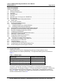
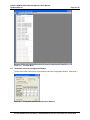
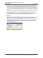
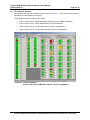
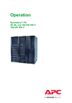
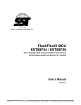
1
BRANCH/SUBFEED CIRCUIT MANAGEMENT
Cyberex BCM-SFCM Configurator/Monitor
User's Manual
Updated: 04/01/13
Thomas & Betts Power Solutions
5900 Eastport Boulevard y Richmond, VA 23231-4453
Tel: 800-238-5000 y Fax: 804-236-4047
Cyberex BCM-SFCM Configurator/Monitor User's Manual
Updated 04/01/13
Page 2 of 30
TABLE OF CONTENTS
TABLE OF CONTENTS ................................................................................................................................ 2
1.0
Program Description........................................................................................................................... 2
2.0
PC System Requirements .................................................................................................................. 3
3.0
Installation .......................................................................................................................................... 3
4.0
The Initial Login .................................................................................................................................. 3
5.0
PC Setup ............................................................................................................................................ 4
6.0
General Comm. Port Usage on the BCM/SFCM ............................................................................... 5
7.0
The View Menu .................................................................................................................................. 5
8.0
The System and Panel Configuration Window .................................................................................. 6
8.1
Panel Types.................................................................................................................................... 7
9.0
The "CB View" Windows .................................................................................................................... 8
10.0
The Branch Readings Windows ................................................................................................... 10
11.0
The Subfeed Windows ................................................................................................................. 10
11.1
Changing Settings on the Subfeed Windows ........................................................................... 11
11.2
Resetting Latched Alarms and Warnings ................................................................................. 11
12.0
Other BCM Branch and SFCM Subfeed Readings Windows ...................................................... 12
13.0
BCM Branch and SFCM Subfeed Configuration Windows .......................................................... 13
14.0
BCM Panel Readings/Configuration Window............................................................................... 14
15.0
Calibrating the BCM/SFCM .......................................................................................................... 15
16.0
Upgrading/Downgrading the BCM/SFCM Firmware .................................................................... 15
17.0
Opening the Terminal Window ..................................................................................................... 17
18.0
Temporarily Closing the PCs Serial Port ...................................................................................... 18
19.0
Creating Service Port Script Files................................................................................................. 19
19.1
Procedure for Creating a New Script File ................................................................................. 22
19.2
Procedure for Creating a "Verify Script File"............................................................................. 23
20.0
Running Service Port Script Files................................................................................................. 24
21.0
Capturing Settings ........................................................................................................................ 25
22.0
Comparing Captured Setting Files ............................................................................................... 26
23.0
Creating Script Files from Captured Settings Files ...................................................................... 28
24.0
Window Arrangement and Navigation Features........................................................................... 30
1.0
Program Description
This program can be used for configuring and monitoring the Cyberex Branch Circuit
Monitor/Subfeed Circuit Monitor (BCM/SFCM). The supported module types are listed below in
Table 1-1.
Table 1-1: Module Types
Module Type
BCM
SFCM (Old CT Arrangement)
BCM/SFCM Unified (Old CT Arrangement)*
BCM/SFCM Unified (New CT Arrangement)*
Firmware Version Examples
0.25
0.23, 0.31, 0.32
1.07 – 1.12
1.16
* The “Old CT Arrangement” and “New CT Arrangement” are explanation below.
The “Old CT Arrangement” and “New CT Arrangement” configurations are determined by the
firmware version. For example, Firmware v1.16 is only for the New CT Arrangement. It affects only
the CT arrangement for the SFCM configuration. These SFCM CT arrangements are shown in
Section 9.0 below. This program can support either arrangement by selecting it in the “PC Setup”
window as detailed below in Section 5.0.
Thomas & Betts Power Solutions y 5900 Eastport Boulevard y Richmond, VA 23231-4453
Cyberex BCM-SFCM Configurator/Monitor User's Manual
Updated 04/01/13
Page 3 of 30
This program supports the configurable Branch Current Zero Cutoff threshold setting (Modbus
Register 863), which is available in BCM firmware version 1.08 and higher. It also supports the
following BCM sensing options, which are available in the “Unified” types:
•
Voltage Sensing Enabled/Disabled
•
L-N/L-L Selection Support (Modbus Register 864)
This feature is supported in “BCM/SFCM Unified” software versions 1.12 and higher.
Note that the “L-L Sensing” option requires a special voltage daughterboard: P/N 41-98-658993
The program can be used in either of the following communications modes: RS-232, RS-485, or
TCP. Only limited configuration can be done when in the RS-485 or TCP modes.
Support for these items are configured in this program as detailed below in Section 5.0.
2.0
3.0
PC System Requirements
•
IBM Pentium or higher (or compatible) PC with a free serial port, network interface card, and a
minimum screen resolution setting of 1024 by 768.
•
Microsoft Windows XP or higher.
•
Microsoft Excel 2003 is needed for certain functions regarding Captured Settings in
Section 22.0.
Installation
This program can be installed by double-clicking the ' BCM-SFCM-CM_Setup_vX_X_X.exe' file
provided and following the on-screen instructions. This setup program will put a shortcut on the
Desktop and in the Windows StartÆPrograms folder.
4.0
The Initial Login
When the program is started, the main window will appear as shown in Figure 4-1 below.
Figure 4-1 – The Main Screen
Thomas & Betts Power Solutions y 5900 Eastport Boulevard y Richmond, VA 23231-4453
Cyberex BCM-SFCM Configurator/Monitor User's Manual
Updated 04/01/13
Page 4 of 30
An initial login is required before using the program. Once you are logged in, you have the option of
logging out between uses, or remaining logged in for future uses. To log in, click FileÆLogin in the
main menu bar. The Login dialog box will open as shown below.
There are three login levels as shown in Table 4-1 below.
Table 4-1: Login Levels
User Name
Default
Password
Permissions
0
Default
Default
Permission to view meter readings and settings only.
1
Administrator
Admin
2
Supervisor
Super
Level
Permission to configure and calibrate the unit in addition to those of
Level 0 (above).
Permission to upgrade/downgrade the unit's firmware, to change the
program's passwords, and to use configuration script files, in addition
to those of Level 1 (above).
When you are finished using the program, you have the option of logging out or remaining logged in
for the next use. To log out, click FileÆLogout in the main menu bar.
5.0
PC Setup
Once you are logged in and you are connected to the DB9 (RS-232) connector on a BCM/SFCM
unit via a null-modem serial cable, the program will start polling the unit. If not, you may need to
change settings on the "PC Setup" dialog box (FileÆPC Setup on the main menu bar) as shown
below.
Note the "Unit Type" setting in the PC Setup dialog box below in Figure 5-1. This should be set for
the type of unit you are accessing. The supported module types are listed in Table 1-1 above.
The radio buttons in the BCM/SFCM-Unified frame must be set only when you are accessing units
in the RS-485 or TCP mode only with the newer type BCM/SFCM-Unified software. Items that do
not need to be set with the various modes and unit types are disabled (grayed-out).
Figure 5-1 – The PC Setup Dialog Box
Thomas & Betts Power Solutions y 5900 Eastport Boulevard y Richmond, VA 23231-4453
Cyberex BCM-SFCM Configurator/Monitor User's Manual
Updated 04/01/13
Page 5 of 30
The “PC Setup" window defaults as shown above in Figure 5-1. The “Firmware Version” selection
is used to limit or add the registers supported and polled. The program may not work correctly if the
wrong version is selected. An explanation of the firmware versions vs. the added registers are
shown in Table 5-1 below.
If needed, select a different setting and click the OK button to save the new setting.
Table 5-1: Firmware Versions
Firmware Modbus Registers Added
Version
v1.08
Register 863 (Branch Current Zero Cutoff) was added. This is a configurable threshold
setting that can be set to force low branch currents to zero. (Readings less than this
setting will appear as zero amps.)
v1.12
Register 864 (L-N / L-L Selection) was added. Note that the “L-L Sensing” option
requires a special voltage daughterboard: P/N 41-98-658993
6.0
General Comm. Port Usage on the BCM/SFCM
The BCM/SFCM is designed to be configured using the RS-232 Mode (via the DB9 connector).
When using this mode, the baud and Slave ID settings can be changed without affecting the
communications. The program uses the various baud, slave ID, IP address, and panel settings in
this window only when in the RS-485 or TCP mode.
In the RS-232 Mode, the baud is always "9600", the Slave ID is always "7", and the program
automatically determines how the four panels are set. The grayed-out settings in the "Comm
Settings" frame of the “PC Setup” dialog box (Figure 5-1 above) show the settings the program will
use when in the RS-485 or TCP mode. These settings will become enabled and can be changed as
required when the mode selection is changed.
7.0
The View Menu
When the program is first installed and you have logged in, there will be no windows selected in the
View menu as shown below in Figure 7-1. The items enabled in the menu depend on if the program
is talking to a BCM/SFCM unit and how the BCM/SFCM's panels are configured. Any combination
of the enabled items in the View menu can be selected to view. When an item is selected, its
window will open and a checkmark will appear next to the item in the menu. The item can be
unselected by either re-clicking the selected item in the menu or by closing its window.
The program remembers the views selected when the program is closed and reopened later. It also
remembers the positions of open windows.
Thomas & Betts Power Solutions y 5900 Eastport Boulevard y Richmond, VA 23231-4453
Cyberex BCM-SFCM Configurator/Monitor User's Manual
Updated 04/01/13
Page 6 of 30
Figure 7-1 – The View Menu
8.0
The System and Panel Configuration Window
The first item on the View menu is for the System and Panel Configuration window. (See below.)
Figure 8-1 – The System and Panel Configuration Window
Thomas & Betts Power Solutions y 5900 Eastport Boulevard y Richmond, VA 23231-4453
Cyberex BCM-SFCM Configurator/Monitor User's Manual
Updated 04/01/13
Page 7 of 30
This window is used for setting the baud setting and the Modbus slave IDs of the BCM/SCFM as
well as some of the other basic system and panel settings. In the example screenshot above,
Firmware Version, “v1.12 (or higher)” is selected in the PC Setup window (Figure 5-1); otherwise, if
“v1.07 (or lower)” were selected, the BCM Voltage Sensing (L-N /L-L) radio buttons and the Branch
Current Zero Cutoff setting would be disabled (grayed-out) in the “System and Panel Configuration”
window.
Other windows are also available for changing the other panel settings, which are addressed below.
You must be logged in on Level 1 or 2 to can change the settings in the “System and Panel
Configuration” window. The items can be changed by clicking the checkboxes or double-clicking
the white text boxes and entering or selecting a new value in the popup window.
8.1
Panel Types
There are five Panel Types supported as shown below in the "Set Panel Type" window. Note that
when Panel Type “0” (BCM – Sequential Numbering) is selected, there are two “Sequential
Numbering” sub-options that can then be selected: One Column (Column Width) or Two Columns.
This window opens by double-clicking one of the Panel Type textboxes in the System and Panel
Configuration window. The Panel Type can then be changed by selecting a different type and
clicking OK as shown below.
Figure 8-2 – The "Set Panel Type" Window
Thomas & Betts Power Solutions y 5900 Eastport Boulevard y Richmond, VA 23231-4453
Cyberex BCM-SFCM Configurator/Monitor User's Manual
Updated 04/01/13
9.0
Page 8 of 30
The "CB View" Windows
An example of the "CB View" windows are show below in Figure 9-1. The window for each panel is
dependent on how the panel is configured.
This example shows the following Panel Types:
•
Panel 1: Panel Type 0 – BCM Sequential Numbering (Column-Width Panelboard)
•
Panel 2: Panel Type 1 – BCM (Standard Two-Column Panelboard)
•
Panel 3: Panel Type 4 – SFCM (with Neutrals) (Old CT Arrangement)
•
Panel 4: Panel Type 5 – SFCM (without Neutrals) (Old CT Arrangement)
Figure 9-1: ‘CB View’ Windows
(Panels 3 & 4 show SFCM Panels with the “Old CT Arrangement”)
Thomas & Betts Power Solutions y 5900 Eastport Boulevard y Richmond, VA 23231-4453
Cyberex BCM-SFCM Configurator/Monitor User's Manual
Updated 04/01/13
Page 9 of 30
The following screenshot example shows the following Panel Types:
•
Panel 1: Panel Type 0 – BCM (Sequential Numbering Two-Column Panelboard)
•
Panel 2: Panel Type 1 – BCM (Standard Two-Column Panelboard)
•
Panel 3: Panel Type 4 – SFCM (with Neutrals) (New CT Arrangement)
•
Panel 4: Panel Type 5 – SFCM (without Neutrals) (New CT Arrangement)
Figure 9-2: ’CB View’ Windows
(Panels 3 & 4 show SFCM Panels with the “New CT Arrangement”)
Left-clicking on any of the CB buttons on the CB View windows will cause the associated Branch or
Subfeed Circuit window to open, as shown in a later section below. Multiple Branch and Subfeed
Circuit windows can be opened at the same time.
Any of the circuits can be disabled or enabled by right-clicking on any of the corresponding CB
buttons on the CB View windows and clicking the Disable or Enable popup, as shown below.
When a circuit is disabled, its CB buttons will appear grey on the CB View window as shown below.
When a circuit is enabled, its CB buttons will appear green if no alarms or warnings exist for that
circuit, or will appear red or yellow if there are any alarms or warnings, respectively.
Thomas & Betts Power Solutions y 5900 Eastport Boulevard y Richmond, VA 23231-4453
Cyberex BCM-SFCM Configurator/Monitor User's Manual
Updated 04/01/13
Page 10 of 30
10.0 The Branch Readings Windows
The Branch Readings windows appear when CB buttons on BCM panels are clicked.
(See Figure 10-1 below.) Active alarms and warnings will appear as red or yellow, respectively.
Figure 10-1 – Branch Readings Window
As with other table-type windows like these, a popup menu appears when you right-click the table
as shown below. In this case, you can use this popup menu to copy the text to the Windows
clipboard, which you can then paste into other applications, like Excel.
Clicking Help in this popup menu opens a Help window that tells you the other things you can do
with this table. In this case, it says you can reset latched alarms or warnings by double-clicking a
cell in the associated column.
Figure 10-2 – Popup Menu for Tables
11.0 The Subfeed Windows
The Subfeed windows appear when CB buttons on SFCM panels are clicked.
(See Figure 11-1 below.)
The metering, alarm/warning states, and configuration settings for each subfeed can be seen in its
Subfeed window as shown below. Active alarms and warnings will appear as red or yellow,
respectively.
Figure 11-1 – Subfeed Window
Thomas & Betts Power Solutions y 5900 Eastport Boulevard y Richmond, VA 23231-4453
Cyberex BCM-SFCM Configurator/Monitor User's Manual
Updated 04/01/13
Page 11 of 30
11.1 Changing Settings on the Subfeed Windows
When logged in on Level 1 or 2, you can change the settings in the Subfeed windows by doubleclicking in the setting you want to change. When this is done, enter the new number into the popup
dialog box that appears as shown below. Any setting inside the "Alarms/Warning and Settings"
frame can be changed like this.
Also, when logged in on Level 1 or 2, you can reset the Min/Max Currents and the KWH readings by
clicking the "Reset Meters" button on the Subfeed window.
Figure 11-2 – Changing Settings in the Subfeed Window
11.2 Resetting Latched Alarms and Warnings
When logged in on Level 1 or 2, and the "Latching Alarms/Warnings" option is enabled (see the
"Latching Alarms/Warnings" checkbox on the System Settings window), you can reset latched
alarms and warnings by double-clicking on the red or yellow alarm/warning boxes on the Subfeed
window. This will reset all of the alarms and/or warnings that are common with a certain Modbus
register. These alarms/warnings are grouped as follows.
• OC Alarms (øA, øB, øC, Neut.)
• OC Warnings (øA, øB, øC)
• UC Alarms (øA, øB, øC)
• Over KW Alarms (øA, øB, øC)
• All OV/UV Alarms/Warnings
• Phase Loss Alarm
Thomas & Betts Power Solutions y 5900 Eastport Boulevard y Richmond, VA 23231-4453
Cyberex BCM-SFCM Configurator/Monitor User's Manual
Updated 04/01/13
Page 12 of 30
12.0 Other BCM Branch and SFCM Subfeed Readings Windows
In addition to the BCM Branch Readings and SFCM Subfeed windows above, which show readings
for only one circuit, there are other windows available in the View menu, which show readings for all
circuits for each of the four panels in a table format. Examples of these are shown below in Figure
12-1 and Figure 12-2, with their popup menus, which appear by right-clicking. The Help window for
these screens state that you can reset latched alarms or warnings by double-clicking a cell in the
associated column in the table.
Figure 12-1 – BCM Branch Readings Window
Figure 12-2 – SFCM Subfeed Readings Window
Thomas & Betts Power Solutions y 5900 Eastport Boulevard y Richmond, VA 23231-4453
Cyberex BCM-SFCM Configurator/Monitor User's Manual
Updated 04/01/13
Page 13 of 30
13.0 BCM Branch and SFCM Subfeed Configuration Windows
The BCM Branch Configuration and SFCM Subfeed Configuration windows show readings for all
circuits for each of the four panels in a table format. Examples of these are shown below in Figure
13-1 and Figure 13-2, with their Table Instructions, which appear by right-clicking and selecting Help
in the popup menu.
The Help windows for these screens state that you can change individual settings by double-clicking
cells. Note that for the BCM Branch Configuration windows, you can change the setting for all
branches in the panel by double-clicking the column header.
Figure 13-1 – BCM Branch Configuration Window
Figure 13-2 – SFCM Subfeed Configuration Window
Thomas & Betts Power Solutions y 5900 Eastport Boulevard y Richmond, VA 23231-4453
Cyberex BCM-SFCM Configurator/Monitor User's Manual
Updated 04/01/13
Page 14 of 30
14.0 BCM Panel Readings/Configuration Window
The BCM Panel Readings/Configuration windows (shown below in Figure 14-1) show the BCM
panel readings and the alarm/warning status and limit settings for each of the four panels.
Instructions for using these windows are in the tooltips, which appear when the mouse is over the
cells. The instructions for using this window are as follows:
• Latched alarms or warnings can be reset by double-clicking the associated cell.
• The limit settings can be changed by double-clicking the associated cell.
BCM Voltage Sensing set for L-N
BCM Voltage Sensing set for L-L
Figure 14-1 – BCM Panel Readings/Configuration Window
Figure 14-1 (above) shows example screenshots with the BCM Voltage Sensing option set for both
“L-N” and “L-L”. (See Section 8.0 above.)
The BCM Panel Configuration window, shown below in Figure 14-2, is also available in the View
menu, where you can change settings by double-clicking the cell. Panel configurations can also be
performed in the System and Panel Configuration Window shown above in Figure 8-1.
Figure 14-2 – BCM Panel Configuration Window
Thomas & Betts Power Solutions y 5900 Eastport Boulevard y Richmond, VA 23231-4453
Cyberex BCM-SFCM Configurator/Monitor User's Manual
Updated 04/01/13
Page 15 of 30
15.0 Calibrating the BCM/SFCM
Note: These functions are available only in RS-232 mode.
When logged in on Level 1 or 2, you can calibrate the BCM/SFCM using the controls on the
Calibration windows, shown below in Figure 15-1, which are opened by selecting Calibration in the
Main Menu.
For calibration instructions, refer the BCM/SFCM User Manual.
Figure 15-1 – BCM/SFCM Calibration Windows
16.0 Upgrading/Downgrading the BCM/SFCM Firmware
You must be in RS-232 mode and logged in on Level 2 to use the BCM/SFCM Configurator
application for upgrading or downgrading the BCM/SFCM firmware. To see the Upgrade window as
shown below in Figure 16-1, select Upgrade in the main menu bar.
When the program is installed, it is not configured with any "Software Upgrade File" paths, which
appear in the combo box in the Upgrade Software page as shown below. Software upgrade file
paths can be added, removed and saved by the program so that they will still be there when the
program is closed and reopened later.
A new software upgrade file path can be added by dragging from Windows Explorer and dropping
into the white "Software Upgrade File" combo box. Then it can be saved for future use by clicking
the Save button.
You can also add a new software upgrade file path by clicking the Browse button just below the
"Software Upgrade File" combo box. A new window will open as shown in Figure 16-2 below. This
is a standard "File->Open" dialog box that lets you browse through folders so that you can find and
select the upgrade file that you need. Click the Open button after selecting the correct upgrade file
as shown below.
Once a new software upgrade file path selected, the Save button (below the white combo box) will
become enabled. You can then save the new software upgrade file path in the list by clicking the
Save button.
To see the software upgrade file paths in the list, click on the down-arrow button on the right-hand
side of the combo box as shown below in Figure 16-3. Then you can select the file that you want to
use for the upgrade.
Note: To remove a path from the list, simply select the path and click the Remove button in that
frame.
When a software upgrade file is selected (like shown in Figure 16-3), you can click the "Open
Folder" button (in the same frame) to open its folder with the file selected in Windows Explorer. This
is handy for checking file dates, etc.
Also note that the software upgrade files should be named with the major revision number following
a ‘v’, which is followed by a ‘_’ as shown in the following example.
bcm_sfcm_v1_12.bin
Thomas & Betts Power Solutions y 5900 Eastport Boulevard y Richmond, VA 23231-4453
Cyberex BCM-SFCM Configurator/Monitor User's Manual
Updated 04/01/13
Page 16 of 30
Otherwise, if the software upgrade file is not named correctly, you may see the following warning
message to appear when the “Upgrade” button is clicked:
The major revision number of the new software (v#) does not match the existing software (v#).
This may be due to a hardware incompatibility.
If this happens, you have the option either to cancel or proceed with the upgrade. (Usually, when
performing software upgrades, the major revision number of the new software should match the
major revision number of the old software.)
Figure 16-1 – Upgrade Window
Figure 16-2 – Browsing Software Upgrade Files
Figure 16-3 – Selecting Saved Software Upgrade Files
Thomas & Betts Power Solutions y 5900 Eastport Boulevard y Richmond, VA 23231-4453
Cyberex BCM-SFCM Configurator/Monitor User's Manual
Updated 04/01/13
Page 17 of 30
Once the software upgrade file is selected, click the Upgrade button to start the upgrade. The File
Transfer Progress bar should start growing and the "Upgrade in process" message should appear
as shown below. The Cancel button can be clicked to stop the upgrade, if needed.
Figure 16-4 – Software Upgrade in Process
The upgrade file transfer takes about 2 ¼ minutes. After the file transfer has completed, you should
see the following message box pop up.
After clicking the OK button, you should see the following message box pop up. After
acknowledging these two messages, the BCM/SFCM should start running with the new software
upgrade loaded.
17.0 Opening the Terminal Window
When logged in on Level 1 or 2, you can open the Terminal window, as shown in Figure 17-1 below,
by selecting ConnectionÆTerminal on the main menu bar. When the Terminal window is open, you
can enter service port commands into the smaller lower textbox.
Thomas & Betts Power Solutions y 5900 Eastport Boulevard y Richmond, VA 23231-4453
Cyberex BCM-SFCM Configurator/Monitor User's Manual
Updated 04/01/13
Page 18 of 30
Figure 17-1 – Terminal Window
18.0 Temporarily Closing the PCs Serial Port
The PC’s serial port can be temporarily closed and reopened without exiting the BCM/SFCM
Configurator application by selecting ConnectionÆDisconnect and ConnectionÆConnect on the
main menu bar. This is convenient to use when you want to temporarily communicate with the
BCM/SFCM with another application.
Thomas & Betts Power Solutions y 5900 Eastport Boulevard y Richmond, VA 23231-4453
Cyberex BCM-SFCM Configurator/Monitor User's Manual
Updated 04/01/13
Page 19 of 30
19.0 Creating Service Port Script Files
This application can be used to create service port script files to use for configuring BCM/SFCM
units and for verifying the settings after configuring. The files can be created without having a
BCM/SFCM connected to the PC.
To open the Create Scripts window, select ScriptsÆCreate Scripts in the main menu bar. The
window will open as shown below.
Figure 19-1 – The Create Scripts Window (Initial View)
The last script file used will be loaded into this form.
The items that appear in the blank list boxes above depend on the Panel Type selected by the
Panel Type radio buttons on the form. For example, the following screenshot shows the window
when "BCM (Std.)" (Panel Type 1) is selected.
Thomas & Betts Power Solutions y 5900 Eastport Boulevard y Richmond, VA 23231-4453
Cyberex BCM-SFCM Configurator/Monitor User's Manual
Updated 04/01/13
Page 20 of 30
Figure 19-2 – The Create Scripts Window: “BCM (Std.)” (Panel Type 1) is Selected
Thomas & Betts Power Solutions y 5900 Eastport Boulevard y Richmond, VA 23231-4453
Cyberex BCM-SFCM Configurator/Monitor User's Manual
Updated 04/01/13
Page 21 of 30
Also, the items available in the Selection frame above depend on the item selected in the list boxes
on the form. For example, the following screenshot shows the window when an item in the "Branch
Settings" list box is selected.
Figure 19-3 – The Create Scripts Window (Branch Settings Item Selected)
The large grid or table that appears (as shown above) is used for selecting the branches, subfeeds,
or panels that you want to change. These items are selected or unselected by clicking or clicking
and dragging the mouse over the cells. The selected cells are highlighted with a dark blue color as
shown in the example below.
The cells in an entire row or column can be selected or unselected by clicking the header for a row
or column. The cells in the entire table can be selected or unselected by clicking the header cell in
the upper right-hand corner of the table.
Thomas & Betts Power Solutions y 5900 Eastport Boulevard y Richmond, VA 23231-4453
Cyberex BCM-SFCM Configurator/Monitor User's Manual
Updated 04/01/13
Page 22 of 30
Figure 19-4 – The Create Scripts Window (Cells Selected)
After cells are selected as shown in the screenshot above, a number can be entered into the New
Setting textbox. Then, when the "Add to Script" button is clicked, a line of text will be added to the
text in the large "Script File Text" textbox for each cell selected as shown above.
19.1 Procedure for Creating a New Script File
The following procedure can be used for creating a new script file.
19.1.1
Clear the Script File Text Box
19.1.1.1 Clear the Script File Text Box by clicking the Clear Text button.
19.1.2
Add System Settings to the Script File Text as Follows:
19.1.2.1 Starting at the upper left-hand corner of the window, select a System Setting you want to add to
the script file by clicking the item in the list box.
19.1.2.2 Enter the new value you want to for this item in the New Setting (white) textbox.
19.1.2.3 Click the Add to Script button to add this command to the script file. The new command line
should appear in the large Script File Text box on the right-hand side of the window.
Note: The text in the Script File Text box can be manual edited or deleted, like using Notepad.
19.1.2.4 You can repeat this process to add other "System Settings" items, if required.
19.1.3
Add Panel Settings to the Script File Text as Follows:
19.1.3.1 Select a Panel Setting you want to add to the script file by clicking the item in the Panel Settings
list box.
Thomas & Betts Power Solutions y 5900 Eastport Boulevard y Richmond, VA 23231-4453
Cyberex BCM-SFCM Configurator/Monitor User's Manual
Updated 04/01/13
Page 23 of 30
19.1.3.2 In the Selection frame, select the panel or panels you want to add by clicking or dragging the
mouse over the appropriate cells in the grid.
19.1.3.3 Enter the new value you want to for this item in the New Setting textbox. (This value will be
used for all panels selected.)
19.1.3.4 Click the Add to Script button to add this item to the script file. The new command line/s should
appear in the Script File Text box on the right-hand side of the window.
19.1.3.5 You can repeat this process to add other "System Settings" items, if required.
19.1.4
Add Branch/Subfeed Settings to the Script File Text as Follows:
19.1.4.1 Select a Branch or Subfeed Setting you want to add to the script file by clicking the item in the
Branch Settings or Subfeed Settings list box.
19.1.4.2 In the Selection frame, select the Branch/es or Subfeed/s and Panel/s you want to add by
clicking or dragging the mouse over the appropriate cells in the grid.
19.1.4.3 Enter the new value you want to for this item in the New Setting textbox. (This value will be
used for all panels selected.)
19.1.4.4 Click the Add to Script button to add this item to the script file. The new command line/s should
appear in the Script File Text box on the right-hand side of the window.
19.1.4.5 You can repeat this process to add other Branch or Subfeed Settings items, if required.
19.1.5
Voltage and Current Offset Calibration:
This application also provides the option of putting Voltage and Current Offset Calibration for
each panel into script file. This is done by selecting the item in the "Calibration Settings" list box
and following the same procedure for adding the other items to the script file as described
above, except that you do not enter a number into the New Setting textbox.
19.1.6
Save the Script File as Follows:
You can edit or delete text in the Script File Text box if necessary. When ready, save the
finished script file by clicking the "Save Script File" button. A "Save As" dialog box will appear,
prompting you for a new file name for the new script file. The default folder for saving script files
is the "\Scripts" subfolder in the application's folder.
19.1.7
Running the Script File:
Once the file has been saved, you can run the script file via terminal mode by clicking the "Run
Script via Terminal" button. This opens the Script File Transfer and Terminal windows as
shown below in Section 20.0. (This is the same as selecting ScriptsÆRun Script via Terminal in
the main menu bar as described in Section 20.0 below.)
The script file can also be run via Modbus by clicking the "Run Script via Modbus" button. The
program converts the script file text into Modbus commands. This runs faster than via Terminal
and can be used with Modbus RTU or Modbus TCP. The voltage and current offset calibration
cannot be done using this method. It can only be used with TLM commands.
19.2 Procedure for Creating a "Verify Script File"
After a new script file has been created, it may be a good idea to create another script file to use for
verifying that the new settings have been actually been saved in the BCM/SFCM after being
configured. This "Verify Script File" or "Read File" can be easily created from an existing setup
script file as follows.
Thomas & Betts Power Solutions y 5900 Eastport Boulevard y Richmond, VA 23231-4453
Cyberex BCM-SFCM Configurator/Monitor User's Manual
Updated 04/01/13
Page 24 of 30
With the script file text in the Script File Text box (e.g., after saving the script file in the procedure
above), click the "Make Read File" button. (This changes the text in the Script File Text box into
commands for reading data instead of writing data to the BCM/SFCM.) Then save the text to a new
file by clicking the "Save Script File" button. In the "Save As" dialog box, which will appear, enter a
new file name that distinguishes this as a "Verify Script File" or "Read File".
20.0 Running Service Port Script Files
This application can be used to run service port script files for configuring BCM/SFCM units and for
verifying the settings after configuring. To open the Script File Transfer window, select
ScriptsÆRun Script in the main menu bar. The window will open and the Terminal window should
open a few seconds later as shown below.
The program will load the last script file used. To load another script file, click the Browse button
and select an existing script file in the "Open" dialog box, which will appear. (The "Script File
Transfer" window can also be opened from the "Create Script File" window by click the "Run Script"
button in that window. When opened this way, the current script file in the "Create Script File"
window will be loaded into the "Script File Transfer" window.)
When you have the correct script file loaded, click the Run button in the "Script File Transfer"
window. You should see the highlighter bar shift down in the "Script" list box and the commands
being echoed in the Terminal Interface textbox in the Terminal window.
Thomas & Betts Power Solutions y 5900 Eastport Boulevard y Richmond, VA 23231-4453
Cyberex BCM-SFCM Configurator/Monitor User's Manual
Updated 04/01/13
Page 25 of 30
21.0 Capturing Settings
To capture the settings, open the “All Settings” window by selecting “View > All Settings” on the
menu bar. After the table has populated (after about 20 seconds), you will see the window caption
change from “Updating” to “Updated”, followed by a timestamp, as shown in the example
screenshot below. Then, right-click on the table and select “Capture to File” on the popup menu as
shown below.
Figure 21-1 – Selecting “Capture to File” in the “All Settings” Window
The program will save the data to a file, which will be named:
Settings_XXX.txt (where XXX is a serialized file number)
The program will then automatically open Windows Explorer with this new file selected, as shown
below in Figure 21-2. This file will be located in the “Downloads” subfolder of the application’s folder
(usually “C:\Program Files\Cyberex BCM-SFCM Configurator-Monitor\Downloads\” for Windows
XP).
Figure 21-2 – Windows Explorer Opens with the New File Selected
Also, at the same time, the program will automatically open the “Select Settings Download Files”
window with the new file added at the bottom of the list, as shown below in Figure 21-3.
Thomas & Betts Power Solutions y 5900 Eastport Boulevard y Richmond, VA 23231-4453
Cyberex BCM-SFCM Configurator/Monitor User's Manual
Updated 04/01/13
Page 26 of 30
Figure 21-3 – The “Select Settings Download Files” Window with the New File Added
22.0 Comparing Captured Setting Files
This program can be used to compare the Captured Settings files. Possible uses for this may be to
compare the settings on one module against another or against a file with the default settings. This
feature can also be used for creating custom script files for configuring modules.
Note that to compare settings in two or more files, the Panel Type settings in the files must match.
For example, if the four Panel Types in the first file are 1, 1, 4, & 5 (respectively for Panels 1, 2, 3, &
4), then the Panel Types in the second file must also be 1, 1, 4, & 5. This rule does not apply to
Panel Types 0 and 1; these types can be compared.
To compare Captured Settings files, open the “Select Settings Download Files” window by selecting
“Tools > Compare Settings” in the menu bar. This window is shown above in Figure 21-3. The
Captured Settings files can be added into the list in this window by dragging and dropping from
Windows Explorer or by right-clicking in the list and selecting “Add New File” in the popup menu.
The following “Default Settings” files are installed with the program:
BCM_Defaults_v1_12_Type_0.txt:
BCM (Sequential Numbering)
BCM_Defaults_v1_12_Type_1.txt:
BCM (Two-Column – Standard)
SFCM_Defaults_v1_12_Type_4.txt: SFCM with Neutrals
SFCM_Defaults_v1_12_Type_5.txt: SFCM without Neutrals
These file are located in the “Default_Settings” subfolder of the application’s folder (usually
“C:\Program Files\Cyberex BCM-SFCM Configurator-Monitor\Default_Settings\” for Windows XP),
which can be opened by right-clicking on file list and selecting “Open Default Settings Folder” in the
popup menu as shown below in Figure 22-1.
Figure 22-1 – Right-Click to Access the Popup Menu
To compare two or more Captured Settings files with each other, simply select them in the “Select
Settings Download Files” window by ticking their checkbox, and then click the “Compare” button as
shown below in Figure 22-2. This will cause the “Compare Setpoints” window to open as shown
below in Figure 22-3.
Thomas & Betts Power Solutions y 5900 Eastport Boulevard y Richmond, VA 23231-4453
Cyberex BCM-SFCM Configurator/Monitor User's Manual
Updated 04/01/13
Page 27 of 30
Figure 22-2 – Select Files and Click the “Compare” Button
Figure 22-3 – The “Compare Setpoints” Window
Note that in the “Compare Setpoints” window, the differences between the files will be highlighted in
yellow, as shown in the example screenshot above.
To view this data in an Excel spreadsheet, right-click on the “Compare Setpoints” window and select
“Open in Excel” in the popup menu as shown below in Figure 22-4. This will cause Excel to open
with the data, as shown below in Figure 22-5. The program will automatically save the Excel file in
the folder with the last selected “Settings Download” file and give it the name of the last selected
“Settings Download” file (but with the “.xls” extension). If a file already exists with this name, you
will have the option of replacing the file or selecting a different filename in a “Save As” dialog box,
which will open.
Note: Microsoft Excel 2003 is required to use this feature.
Figure 22-4 – Right-Click to Access the Popup Menu
Thomas & Betts Power Solutions y 5900 Eastport Boulevard y Richmond, VA 23231-4453
Cyberex BCM-SFCM Configurator/Monitor User's Manual
Updated 04/01/13
Page 28 of 30
Figure 22-5 – Excel Opens with the Setpoint Data
To get a better view of the differences, right-click on the “Compare Setpoints” window (Figure 22-4
above) and select “List Differences” in the popup menu. This will cause the “Differences” window to
open as shown below in Figure 22-6.
Figure 22-6 – The “Differences” Window
The cyan-highlighted rows in the “Differences” window indicate items that will not be used when
creating script files based on the differences. In the example screenshot above, the Software
(Minor) Version is highlighted, which is not a setting that can be changed using a script file.
23.0 Creating Script Files from Captured Settings Files
To create service port script files based on the differences shown in the “Differences” window, rightclick in the window and select “Create Script” in the popup menu as shown below in Figure 23-1.
This will cause the “Create Scripts” window to open with the script file text filled in, as shown below
in Figure 23-2.
Thomas & Betts Power Solutions y 5900 Eastport Boulevard y Richmond, VA 23231-4453
Cyberex BCM-SFCM Configurator/Monitor User's Manual
Updated 04/01/13
Page 29 of 30
Figure 23-1 – Right-Click and Select “Create Script”
The script file will have the commands to change the settings to those in the first column shown in
the “Difference” window. For example, in the example screenshot shown above, the script file will
have the commands to change a unit’s settings to those shown in the “Settings_001” column.
Figure 23-2 – The “Create Script” Window Opens with the Script File Text
Note that you can edit or delete text in the Script File Text box if necessary.
The script file can now be run via Modbus by clicking the "Run Script via Modbus" button in the
“Create Script” window (above). The program converts the script file text into Modbus commands.
This runs faster than via Terminal and can be used with Modbus RTU or Modbus TCP.
Thomas & Betts Power Solutions y 5900 Eastport Boulevard y Richmond, VA 23231-4453
Cyberex BCM-SFCM Configurator/Monitor User's Manual
Updated 04/01/13
Page 30 of 30
You can also save the script file by clicking the “Save Script File” button. Once the file has been
saved, you can run the script file via terminal mode by clicking the "Run Script via Terminal" button.
This opens the Script File Transfer and Terminal windows as shown in Section 20.0 above. (This is
the same as selecting ScriptsÆRun Script via Terminal in the main menu bar as described in
Section 20.0.)
24.0 Window Arrangement and Navigation Features
The child windows can be automatically arranged inside of the main parent window by selecting
"Cascade" or "Tile" in the menu under "Window" as shown below, or by simply pressing the F2 or
F3 key, respectively. If "Tile" is selected when there are a lot of child windows open, some of them
will usually go out of the viewing area and a vertical scrollbar will then appear. You can then use
this scrollbar (with the mouse) to view the child windows that are currently out of the viewing area.
The scrollbars on the main parent window can also be operated by the navigation keys on the
keyboard as follows. First, press the F4 key (or select WindowÆScroll Mode as shown below) to
enter a special "Scroll Mode". When in Scroll Mode, the Page Up, Page Down, and arrow keys will
operate the scrollbars on the main parent window. To exit Scroll Mode, press the Esc key, or click
the mouse anywhere.
Selecting the "Close All Windows" item in the menu below will close all open child windows.
Thomas & Betts Power Solutions y 5900 Eastport Boulevard y Richmond, VA 23231-4453