1
'.-: !:.1
t':
i L r-.1
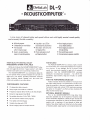
Your Next
Musical lnstrument
Should be the
ACOUSTICOMPUTER'
by DeltaLab
Why wait any longer? Many of the eading qroups in the
U.S., Eng and, and Europe already have theirs, as do the
most advanced record lng studlos.
What is an ACOUSTICOMPUTER? Simply the cleanest
sounding, most f exlb e, widest range dig taldelay and
special'ef fects processor.
ACOUSTICOMPUTER - des gned and manufactured by
DeltaLab, makers of the famous DL-1 Delay Line, whose
sound was described by Modern Recording as "The best
we have encounlered in any digitai de ay unit."
lf you are serious about creative music-making,
you need the AcousTlcoMPUTER now:
o
Especially now that the advent of digita recordlng
demands clean, wide-ranqe sound from every e ement
in the s gnal path. ls a processor really good enough lf
doesn't have the 90dB dynamic range and full 15kHz
bandwidth of De ta Lab gear?
it
o Especially now when audiences increasingLy expect
every live performance to "sound as good as the record."
e Especially now when money is tight' lt only rnakes
to buy a device that does it al
Doub ing, tripling, chorus effect,
S apback, multiple echoes, stereo reverberation;
F anging, tuned resonance, R2D2 effects;
Voca broadening and enhancement, spatial depth;
Vibrato, tremolo, pitch shitting;
Ano -any mo'e. .
When you consider its road worthy construction, highlymusical sound quality, tremendous flexibility - and
when you hear for yourself whal it can do in the creative
process you may tind the price of the ACOUSTICOIVPUTER surprisingly modest. Why wait any longer?
sense
:
.
.
.
.
.
.
DL-2
Deltalab
- R(OUSTICOMPUTER'.
A true stereo (2 channel) delay and special effects unit with hishly musical sound quality
and extremely flexible versatility.
.
.
o
.
16 Revetb
2
ptognns
Inderyndent
Uereveft
Loag delays - up t0252 ns
o
Shon delays - down to 0.25 ns
4:l frequency range
Sustain
-
non-detetionting
for flanging eflects
o
rcpeat with selectable updating
and llanging feedback
HIGH OUALITY DIGITAL DELAY
DehaLab introduces the ACOUSTICON4PUTE
R,@ a
flex-
The ACOUSTICOMPUTER is a combination digital delay and special effects processor designed for use both on
stage and in the studio, providing well-known functions
(echo, doubling, vibrato, flanglng, etc.) plus some new
effecls not available in any other device.
PERFORMANCE FEATURES
2 lndependent delay channels
Delay lengths from 0.25 ms to 252 ms
to 15 kHz at all delay lengths
No audible distortion (1 kHz THD <0.2%)
16 lnter-channel related reverb programs
Foot pedal controlled bypass
Variable time base with VCO
Stereo imaging input and output controls
inagingon input to
extact hidden anbience
Sterco inaging on output
Iot
kft-right shifting
Foot switch bypass contrcl
Extenal nen\ry expawi,n apability
The ACOUSTICOIVIPUTE R ls a compact, highly versatile
musical sound quality and a surprisingly modest price.
Dynamic range greater than 90 dB
Stereo
FOR STUDIO
ible and rugged all-electronic "space machine" with highly
Frequency response 20
.
.
.
revefi
Positive and negative
PROCESSING IS NOW AVAILABLE
O
a
a
o
.
o
a
a
a
c
(seilal node) for specnl effeus
delays
VCO sinusoidal
with
o
true stereo delay line incorporating feedback and equalization circuitry. ln one package, the DL-2 contains what
would have previously required a rack full of outboard
equipment. And the ACOUSTICOMPUTER maintains
DeltaLab's no-compromise reputation -" full 20-15 kHz
bandwidth, large dynamic range and virtually no audible
d
istortion.
FOR THE PERFORMING MUSICIAN
Today's musician knows the problem of trying to
recre-
ate studio effects during a live performance. The DL-2 provides this versatility in one easy to understand, reliable unit.
Footswitch bypass and external VCO inputs give musicians
the option to "pre"select" an effect and also modulate the
effect via the external input.
OPTIONAL MEMORY MODULE
Prior to the ACOUSTICOMPUTE R, long delay times
have been available only at the expense of dynamic range
and/or bandwidth degradation. DeltaLab again chooses the
no-compromise alternative by of{ering an external memory
module
with a maximum of two
seconds
of delay
per
module. Now delay lengths are limited only by the number
of modules added; signal quality is not compromised at all!
DeltaLab ACOUSTICOMPUTER - DL-2
'Nl
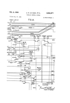
'our
Block Diasram- ACOUSTICOI\TPUTER (One Channet Onty)
SPECIFICATIONS
Delay Ranqe
0.5 to 160 ms
0.25 to 92 ms
Frequency Response'
{@ -14 dA} +r. -3 dB
Ch A
Ch B
20 to 15k Hz
(X1 Delay factor)
90 dB min
85 dB min
Dynamic
A-Weighted
C-Weighted (Broadband)
Serial l\lode
0-5 to 160 ms Ch A
0.75 to 252 ms ch a &
B
(X4 Delay factor)
85 dB min
80 dB min
6 dB
Equivalent Pr€'emphasis
50ps
THD {Distortion Plus
Ref 1 kHz
0dB
-10
-20
-30
-40
{X1 Delay factor)
(X4 Delay factor)
O.2% max
OA% max
dB
O.2a/.
max
O.4"/.
max
da
0.3% max
0-5% max
0.8% max
0.6'10
max
dB
dB
0.8% max
1.0% max
lnputs
Balanced {X LR}
Unbalanced (Phonel
lmpedance
0
0
to 18 dBm
to 'i8 dBm
47K ohm
Outputs
Up to 24 dBm
Up to 18 dBm
600 ohms
Balanced lXLR)
Unb6lanced lPhone)
lmpedance
Delay Faclor
VCO Depth
VCO Rato
Continuous from X1 to X4
0 to 100% ol Delay Adjustment Ranse (4:1)
Sinusoidal from 0 to greater than 10 Hz
Repeats signal in memory indefinitely
without
deqradation. Sample mode is used to update with
new information at rate determined by the VCO.
16 Programs displayed via binary weiqhted LED,s.
Most programs consist of high echo densities.
1% x 19 x 10 in. 14.45 t 4a.3 x 25.4 cm
12 lbs
Size
I
Straight Delay [,4ode
']
With C Weiqhted Eroadband Firter
Nlanufacturer reserves the right to make improvements without obligation.
DeltaLah
Deltalab Research, lnc.
27 lndustrial Avenue, Chelmsford, Mass.0l824, Tel. (617)256,9034
P
B
rNTED lN U.S.A. O1979
DE
LTA LAB
Fi
ESEARCh, INC.
DL 2
1/at
5M
PME
Delto lob f)12 Acousticomputer
by Dave Hastilow
-f-he small srudio
operaror or musician is
^
hit by two facts oflife. The firsr one is
rhat producers often take their bands ro
well-equipped studios, and the second is
that equipping a studio or PA rack costs a
lot of money. Especially a rack full of
what are fast becoming the'obligarory
ancillaries' such as digital delay, flanger,
etc etc.
However, well+quipped studios have
to update their hourly rares to cover costs
so not-so-well-off operato$ can score a
double direct hit if they find one piece of
equipment which will do the rvork of
a
rack full and is moderately enough priced
to iustify keeping the hourly rate dorvn.
The other fact of life is that producers
always have their eyes open
for
less
expensive well-equipped studios, so you
might score another hit if a producer
looks in your direcrion after he's heard a
few of your demos or happens to be at
your gig.
Delta Lab, who have the interests of
the small as well as the big wigs at heart,
have had their thinking caps on and have
produced what appears to be one of the
best ideas in a long rime - rhe DLj
Acousticomputer. Basically what it all
boils down to is that they've taken a 19in
x lfin x 8in box and filled it
with
enough elecronics to give the user access
to every type of elfect from digital delay,
ADT, flanging, reverberation, ambient
reverberation, rear cbannel ambience
exraction, digital sample flanging, digital
random flanging, digital random sample
flanging, echo, cardboard rube echo,
slapback, rotadng speaker, vibrato,
chorus vibrato, simultaneous reverb phasing, simultaneous echo phasing and all of
the effects in bctween the above knob
Davz Hasrtow
ts a
ft.
ot ding
engincet at Eet Pia
settings (which can be pretty mind boggling), and they're all in stereo. How does it
work? Read on - you mighr be able to
Acottsticomputer is that everv dclav tap
rvithin the device has a binarl' addrcss
code or numbcr bctrveen 0 and 15, and the
aff'ord it.
Dl,-2 can selcct any numbcr and
delayed from .5 to 152 ms and Channel B
a given samplc rate determined by the
position ofthe revcrb knob.'I'his is a brief
descnpt ion ofwhat th< DL 2 Acoustitomputer does in its simplest mode and it is
possibly the closest electrooic approach io
artificial ambience crearion short of
playing rhe guitar track back through a
Basically, and in the simplest words
available at rhis timc on Sunday evening.
the two input channels A and B enter the
device and are each routed through two
independent side chains which may remain independent or may interact with
each other depending upon which mode of
operation is selected. Channel A may be
rcgcncratc rl or lt cun scan Iha wh,rlc s('ries
offilieen addresscs and select randomly at
from .25 to 88 ms with the DL-2 in the
parallcl mode. However, in the 'serial'
speaker in the studio and recording it.
mode the inputs are mixed and processed
Acousticomputer can not only regenerate
random selected short and long delaved
signals but also feed back or sustain thcm
firsr through Channel A and then Chan-
nel B. 'fhe output ofChanncl B is delayed
by rhe sum of Channel A and Channel B
indicators. Also the Channel ts data is
trvice processed. I told you it was simple.
In practical terms imagine rhe situation
rvhere you are trying to get an ambient
guitar sound from a dry miked guitar
track. Had the guitar amp been in the
middle of the empty studio or room and
had the mic been stereo the sound rvaves
hitting the mic would have consisted of
the direct sound from the amp mixed rvith
muhiphase delayed sound rvaves arriving
a short time later after being reflecred off
the rvalls, Iloor and ceiling. 1'his
is
essentrally whar the Dl 2 is doing rn rts
most basic mode. Channel A delay and
Channel B delay are in effect rhe walls
around the amp, the reflcctions from the
walis are mixing together somervhcrc in
the middle of the room. and is the casc
with the Dl-2 when the Image control is
in the A,/B position and the resultant
blend of rlrv plus delaled infrrrmatiun
gives the ambient efltct.'l'he reason l)cha
I-ab have labelled the DL-2
rhc
To complete the picrure
to
simulate the build-up
of
the
rvhar
is
described in books on acoustics as
'equilibrium intensity', where the direct
and indirecr sounds from a sound source
have built up to their highest level. Sound
waves bounce around a room until the
energy within them has been dissipated.
Vhile they've been bouncing they will
have had their frequency content altered
considcrably by the acoustic properties of
rhe materials lining the walls of rhe
studio. This effect is simulated in the
Acousticomputer by adjusting the
equalisation of the signals which are
being fed back to the input for regeneration. 'l he equalisation controls consist of
high and low pass frlters.
'fhe front panel can be divided into six
sections which are further sectionalised
by the nature of the controls under these
headings. Now that I have described rvhat
the Acousticompurer does I hope that
will make more
these individual controls
sense.
,>
PME
DELTA LAB DL2
INPUT SECTION
Headrcom indicotot: 'Iwo columns of LED5
indicating peak and slew level berween 40db and
0db.
le'el
and
Conrrol; Adjusrs inpur level ofChannel A
ll srmuhaneously.
/rrage:'l'hree setings - Norrnj Signals
pass
straight through ro their respecrive channels..4 @
Bj Each channel is mixed wirh a mulliphase signal
liom rhc olhcr channel lo cxrracr ambience. R?rr
Signals are dirccrrd to opposire channcl isrereo
PROGRAM
.Sllrr.rtr: In cssencc an infinite rep€a( conrrol.
\\'hcn ,rr rhc input is diconnccled and data is
rccirclllated indelinirely lvrrh no degrarion. ln rhe
jd,r/,1. modc rhc on/oiI function swilches ar
a
rarc
.(r h\ (h( \'( U. N.\\ Jara r. IoadcJ rnro rhe r.g,{er
in rhe'olf funcrion and circulaled in rhe'on'
l-uncrion. l his I'acility makes possrble a new ellecr 'l)igital Step lrlanging'. I he susrain luncrion may
b! a lbor pcdal.
Inpurs arc mixed rhrough
Channcl A and then B. l hc ourpur ofchanncl A is
bc s\r'rtchcd on
M{rdej Scrial
dclaYcd bv rhe ChannelA indicarion. I heourpur ol'
Channcl ll is dclavcd bv rhc sum of rhe channcl A
dnJ B rnJr(a on. Ako rh( ( hannel tt rndicar$n\
arc ($icc proccsscd.
I'drall(l I ach chann(l
rmagc
r\ mrxed vra rhc rnpdr
cont.ol and processed indepcndcnrl!". Ihe
rcrcrberalron
Rcr.rl
\
rll be inlerrelarcd.
A\ alr(dd\ mcnuoncd. rhcre arc \rxr(cn
rcvcrbcralion programs s(orcd rn the Dl- 2 which
creatc cllecrs rarving beFvecn s€nsalions ol'
sDaciorJsness, Iiurrcr, and rubev etfccrs depending
upon th€ sellings ol lhe 'l'ime Base Generaror,
Revcrberalion, and Mix conlrols.'fhe programs
are selecled by lhe reverbconlrol
Manual Allows ustr ro sel€it J(lav lrme se[ings
in rach channel.
Hold - Locks in program di spl ayed
Select Program change. rn a slow counr'ng
manner unll the knob is rotatcd to the
hold position
Random- Program changes at a rate determined
by position ofknob
DEI-AY
Moving thc switches forward or backward
respectively inc.ease or decrease the initial delays
rn each channel by the amount indicated in figures
above and below the t-ighr Emiuing Diodes. Short
delays are used for flanging and long delays for
spalial or echo elTecls. ln rhe parallel mode channel
Il behaves in the same manner as channel A bul in
the scrial mode the inirial delay ofchannel B ourput
will be the sum of the delays indicared by both the
Channel A t-ED and Channel B LED. This mcans
that Channel B becomesChannelA + B.
REVERIiERATION
'fhe rcverb mix control mixes rhe long and shorl
reflections to creare rcve.beralion- In the 'shorr'
position only short rcflections lvill be regeneraled.
In thc'long' position only long{elayed reflectjons
a.e regcnerated. In rhe 'equal' posilion
€qual
amounrs ofshort and long are fed back. In practical
tcrms the 'shorl' position corresponds to the
reverberation ofa small room and so on.
A and Channel B short and long initial
reflections which are recirculated ro
create reverberation. LEDs 8 and 4
indicate the short and long initial
reflecrions of Channel A and LEDs 2 and
I the short and long initial reflections of
Channel B.
The precise amount of shorl and long
initial reflecrions recirculated to create
the 6nal reverberation pattern is determined by the position of the Reverb
Mix control.
ln operation the Acoutticomputet does
everyrhing it says it can and more . It rs not
possible to describe in words the effects
E:,ludliaioa: l.ou conrrol rollr ufI los frcquen crealed when the knobs are in the
cies in lhe regenerared delayed signals. Ar full cul
intermediate settings and ir is advisable to
passcs liequencies abovc 800 Hertz only. High
make
slight rather than large adjustments
conlrol rolls off evervrhing above l.5kHz.
I'ccdbacA: l)etermines lhe amplitude of signals to the knobs when looking for ellects to
being fcd back. Al max +. signals are fed back in prevent overloading other equipment
with inpur. Ar zeroJ outpur has no .everberalion. At max -, reflecrions are fed back our ofphase
wilh inpur.
phase
TIME BASE GENERATOR
Delay l;actor: \'aries th€ basic clock fr€qumcy
which dctermines the delay; rhus acring as a
variable delay mulliplicr. \'ariable berween x I and
rvhich may be inrerfaced with
it. It
is
possible to set up quite a simple program
and flrck the paralleVseries and sustain
switches only to be knocked our by
something else, so beware of Acouslicomputeritis, or sidetrackingl The chorus
effect
is quite
astounding; so
is
rhe
rotating speaker, and rhe reverberation is
similar in texture to that provided by a
frequency thus makng decp ffange and pirch reasonably-priced spring. The input and
bending possible.
output connections are balanced and
unbalanced which makes for good mobiliOUTPTIT
/rac6c: As with the input imaSe control allowing ty btween srudio and stage and three
subtlc stcreo effects ro bcc.eared.
sockets allow for the sustain and bypass
,Iy',r: Allows lhe source (b!,pass) or rh€ delayed modes to be switched by footpedal or for
signals onlv to appcar ar lhe ourpuls or a mix of
insertion of an external control voltage of
borh when thc knob is set in thecqual posrrion.
VCO Rate and Depth:Rate variable betlveen 0
and l0 Hz. Dep!h control vari€s amplitude ofVCO
'I he DL 2 can b€ bypassed bv using a fooipedal
rvhich plugs into rhe back ofrhe unir.
between 0 and 10v. Provision is also made
for an optional memory module, which
increases the DL 2 memory capabiliry ro 2
ot the front seconds. to be inserted via a j pin
panel are set four LEDS which ar€ Switchcraft connector. The increased
ln the Program
section
numbered 1 2 4 8 upwards. These indicate delay rime will not degrade any of the
the binary address codes for the Channel DL 2 Acousticompurer funcrions.l
Reprint6d by permlssion lrom th€ Ocrobsr 1979 t$uo of
SOUND INTEFINATIONAL MAGAZINE OSOUNO INTER.
NATIONAL LINK HOUSE PUSLICATIONS, LTD.,'I979
Deltalab DL-z
Acousticomputer
By John Murphy and Jim Ford
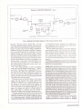
General Description: The DL-2 is not a
simple
piece of equipment either in its functions or in the con-
trol of those functions. In general it is appropriate for
novice users of complex signal processing equipment
(such as the DL-2) to first carefully learn the operation
of the unit. Studying a block diagram showing signal
flow through the unit lsee Figure 1 for a block diagram
of one channel of the DL-2) is usually the quickest way
to learn how it operates. Knowing the operation, it
then becomes easier to use it to maximum advantage.
The operation of the DL-2 can probably be best
it as a pair of digital delay lines
that can be used in many different configurations.
Each of theee delay lines has one input and three separate outputs corresponding to three different time
understood by viewing
delays along the line. Of these three outputs, the middle one is used as the main output of the delay line
while the other two outputs are made available to be
fed back to the delay line input for reverberation and
repeating echo effects. The feedback network incorporates high and low frequency attenuation controls for
coloring the reverberation as well as a "mix" control
for adjusting the balance between the short and long
delays fed back to the input. In addition, the feedback
signal can be either phase inverted or not,
The delay time of the delay line is adjusted in two
steps. First, a pair of momentary toggle switches are
used to set the coarse delay time with horizontal rows
of LEDs indicating the range of delay selected. Then
the delay time of the pair of delay lines is fine adjusted
over a four-to-one range using the "delay factor" control. A VCO (Voliage Controlled Oscillator) in the time
base generator section of the DL-2 can be used to vary
the delay time. Both the depth and rate of the VCO are
adjustable. Mixing the direct and delayed sound while
using very short delays (0.1 to about I milliseconds)
and a slow
srMeep rate provides the familiar swept
comb filter sound of "flanging." A vibrato effect can
be created by using a short delay and selecting only
the delayed signal in the output mix. The depth and
rate .controls of the VCO then control the depth and
rate of the vibrato.
Reverberation is synthesized in the DL-2 by recirculating (or feeding back to the input) the long and short
delays of the two channels. The fraction of the output
signal fed back to the input determines the decay characteristics of the reverb. The greater the feedback percentage the longer it will take for the reverberation to
decay. When either the highs or lows are attenuated in
the {eedback loop the decay time for the attenuated
Repr.inted by permission of Modern Recording, copyright Cowan publishing.
Input level and image controls are located just to the
right o{ the headroom indicators. The input level con"
trol simultaneously adjusts the input signal level for
both channels. The input image control dLects the signals to the opposite channel as the control is rotated
from normal to reverse.
frequencies is reduced in comparison to the other frequencies. With the DL-2 the best sounding reverberation is typically obtained by using a fair bit of low frequency attenuation and near maximum feedback.
The reverberation output for channel A is made up
of recirculated delays from both channels A and B.
Likewise for channel B. There is one long and one short
delay from each of the two channels available for feed"
back to the input. This gives a total of four discrete
delays that can be fed back in various combinations.
Which of these delays is used for feedback depends on
the setting of the DL-z's program indicator. The program indicator is composed of four LEDs that are
either on or off. The four LEDs indicate the presence
(or absence) of each of the four available delavs in the
reverberation. Deltalab has a novel way of allowing
the user to select any of sixteen possible combinations
of these four deLays. When the reverb program control
is placed in the select position the LEDs cycle on and
ofl in a binary counting sequence thus stepping
through the sixteen combinations of discrete delavs
corresponding to sixteen different reverb..programs."
When the desired program is reached the reverb program knob is set to the "Hold" position and the program sequencing stops where it is. If desired, the
reverb program knob can be left in the sequence position and the reverb character will change continually
as the unit aequences through its sixteen reverb pro-
grams. Rotating the reverb program control further
clockwise to its "Random" setting increases the rate
at which the DL-2 steps through the program cycle.
The input controls for the DL-z are located at the
left side of the frout panel. First there are sigaal head-
room indicators which indicate slewing headroom as
well ae peak level (amplitude) headroom. Each display
cousists of four LEDs labeled 0, 10, 20 and 40 dB.
FEBRUARY 1980
Located at the right oi the input controls are the
reverb program controls. The first control in this
group is a three"position toggle switch tabeled ,,Sustain." In the "Ou" position of this switch the input to
the delay line is disconnected and the signal currently
in nemory is recirculated indefinitely with no degradation. Returning the switch to the center or ',Off" posi.
tion returns normal operation of the unit. The third
position of the switch is labeled "Sample" and with the
switch in this position the sustain function alternates
between on and off at a rate set by the VCO. Deltalab
recommends using the "Sample" feature with the DL2 set up for flanging to obtaiu a "digital step flanging,'
effect. The sustain function can be switched on and off
via a footswitch jack located on the rear of the unit,
Nert to the sustain switch is a two-position toggle
switch labeled "Mode" with the positions labeled
"Parallel" and "Serial." In the serial mode the two
channel inputs are mixed and processed through channel A and then through channel B. The output of A is
then delayed by the amount indicated for channel A.
However, the output of channel B is now delayed by
the sum of the delays indicated for A and B. Switching
to the parallel mode, ihe two input sigaals are mixed
(through the image contrcl) and then processed inde-
pendently, However, the reverberation for the two
channels will be inte.related.
The final control in this group is the reverb program
control previously discussed. The program indicator is
located between the mode switch and the reverb proglam control.
Delay times {or the two delay Iines are adjusted by
way of t,!vo momentary-type toggle switches located
one above the other. The LED displays to the right of
the switches indicate the 4 to 1 range of dehy limes
selected for each channel. The range of delay times
available is 0.5 ms (milliseconds) to 152 ms for channel
A and 0.25 ms to 88 ms for channel B. When used for
reverb these initial delays become pre-reverb delays.
Next, and just to the right of the center of the front
pauel is a group of four rotary controls labeled ,,Rever.
DeltaLab ACOUSTICOMPUTER - DL-2
81ock Diasram- ACOUSTICOMPUTER {One ChanneL Only)
Fig.
l:
DellaLab DL.2: Block diagram of lhe unit (one channelonly).
beration." The fAst control, "Reverb Mix," seis the
mix of long and short delays fed back to the delay line
input. This control simultaneously adjusts the relative
levels of the four long and short delays available for
feedback. The next two conirols are labeled "Equaliza'
tion" and provide high and low frequency cuts when
backed off from their full clockwise "Flat" settings.
The last reverberation control is the feedback control,
With this control in the twelve o'clock position none of
lhe delayed sigaals are fed back to the inputs. RoLat'
ing the control clockwise provides increasingly more
feedback signal to the inputs. Counterclockwise rotation resulls in increasingly more of the delayed out'
puts being fed back to the inputs except that the outputs are tirst phase inverted.
The "Time Base Generator" is next and employs
three rotary controls labeled "Delay Factor," "Depth"
and "Rate." The delay lactor is adjustable from 1 to 4
and provides fine delay time adjustment in conjunc'
tion with the coarse delay adjustment already discussed. The other two conlrols adjust the depth and
rate of the VCO. The VCO can be externally controlled
via a phone jack on the rear panel.
The final controls on the front panel are the output
image and mix controls. The image control inte!'
changes the channels as it is rotated clockwise fiom
the normal to the reverse setting. The output mix
control allows the direct and processed (delayed) sig'
nals to be mixed in the desired proportions. At the
right of the output mix control is a bypass indicator'
This LED lights to indicate that the system is
bypassed through use of a rear panel foorswitch jack.
The input connectors for the DL-2 are located on the
rear panel. The unit accepts balanced inputs by way of
XLR-type connectors and accepts unbalanced inputs
via %-inch phone plugs. Likewise, both balanced and
unbalanced outputs are provided employing XLR and
%-inch phone connectors, respectiveiy. A single screwdriver-adjustable control simultaneousiy adjusts the
output levels of the two channels.
The rear panel houses three %'inch phone jacks for
interfacing the bypass, VCO and repeat foot controlsThere is also a five pin XLR-type colnecior for interfacing optional memory modules. IIext to this connec'
Lor is a slide switch labeted "l"{emory" with internal
and external switch positions. firJess external menory is used, this switch should be left in the "lnternal"
position.
The DL-Z is packaged in a single space rack mount
chassis and provides quiie a lot of signal processing
capability in very little space.
Field Test:
We tried out ihe DL-2 during a leisurely
session an<i were quiie pleased
recording
four-track
with the wide variety of efiects that we could otrtain.
Deltalab has provided diagrams which indicate control settings for some nineteen different effects and we
experimented with nearly all of them. In addilion there
are blank coqtrol diagrams which allow the user io
record control settings for additional effects. We tried
the suAgested "guitar reverb" control settings and
were pleased with the results. The eflect combined
some audibly discrete echos along with more dilluse
reverberation to provide a rather tasty combination of
echo and reverb. The effect identified as "ambient
reverb" provided what seemed to be the most natural
seunding reverb for the unit. Even though this was a
good reverb effect it lacked the quality of lush diffusion that is generally demanded of the finest land costlierl reverberators. However, in many applicalions the
DL-z will provide quite satislactory reverb.
Other classifications ol effects that we found useful,
besides reverberation, include varieties of flanging
(Deltalab provides five control recipes for flanging
MODERN RECORDING
effects), echo (four recipes provided), vibrato and doubling/chorusing. We used the DL-2 to flange the oui'
put of an electric piano with excellent results. We were
especially pleased with the consistently high level of
audio quality when we processed signals through the
unit. There was never any loss of highs and the unit's
rioise was never heard. The Acousticomputer is really
quite a high-quality device!
We performed our usual listening test by incorporating the DL-2 into a tape loop on our preamplifier. The
DL-2 was set for 15 ms delay in each channel with no
feedback or VCO employed. The output mix control
was set to lull delay so that we coulC listen through the
delay chain with no other effects. When we played a
disc back through our reference system we heard virtuaily no degradation when we introduced the DL-2 into
the chain. I must say though that we allowed the DL-z
a healthy amount of headroom and were careful not Lo
press the sigaal levels. In any event ii was quite transparent and introduced no sound of its own.
Lab Test: We performed the usual variety of t€sts
on the DL-2 and the specific results are provided in the
"Lab Test Summary." We noted that the input section
does not trave a lot of gain as an i[put signal level of
-2.2 dBV is required for a 0 dB headroom indication
Even though this appears to be the equivalent of a
nominal "0 VU," some caution is necessary in setting
levels through the DL-2 as there is only about 5 dB of
headroom before clipping above the "0 dB headroom"
indicaLion. However, because of the low noise level of
the unit (about 88 dB below 0 dB headroom) it
shouldn't be necessary to push the inpui level. The
output level at 0 dB indication was + 15.0 dBV with
the output level control at maximum, so there is plenty
oi outpui level.
The THD distortion at 0 dB headroom indication
was about 0.1?o in the midrange with the delay factor
control ai the X1 setting. Increasing lhe delay factor
lo X4 increased the mid-frequency distortion to 0.367o.
Distortion also increases at the low and especially the
high frequency extremes. The bandwidth through the
delay line is beiier than 15 kHz, which is excellent
This wide bandwidth was not degraded with any control setiings.
The slew rate limit ihrough the delay lines was measured as 0.4 volts per microsecond. At a 0 dB headroom level (* 15 dBV output level) this provides a slew
rale ratio of 0.065 volts per microsecond. A couple of
simple calculations reveal that in order to maintain a
slew rate ratio of 0.5 {the recommended minimum} or
higher, sigaal levels thrcugh the delay line must be no
higher than 1?.? dB below the 0 dB headroom indication. With the output level control at maximum this
would restrict the output signal level to less than -2.7
dBV. Slewing performance for the direct sigaal path is
better. The direct output could not be driven into slew
limiting because the small signal bandwidth (18.7 kHz)
is less than the power bandwidth through the "direct"
signal chain. If the power bandwidth were just equal to
the small signal bandwidth then the slew rate limit
would be (from calculations) 1.3 volts per microsecond.
Therefore the actuat slew rate limit tbrough the direct
path is at least 1.3 volts per microsecond. Calculating
the slew rate ratio based on this slew rate limii it was
deiermined that the slew rate ratio will be at least O.2l
for 0 dB dB headroom signal levels' Keeping sigral
levels below -?.5 dB headroom {*7.5 dBV ouiput) will
insure that the slew rate ratio never drops below 0 5
for the direct signal path.
The preliminary owner's manual that $'e received
with the DL-2 provided good explanations of the operation of the front panel controls and should allow users
to get good results quickly'
Conclusion: The DL-2 Acousticomputer by Delta'
Lab proved to be a highly versatile digital delay sound
eJfects unit. It provides high quality flanging and dou-
bling effects with many subtle variations. Although
its reverberation is not in the same class as the best
reverberaLors available, it does provide a good reverb
sound that will te satisfactory in many applications.
In our listering tests we were impressed with the con'
sistenily high level of audio quality when listedng
through the unit. The Deltalab Acousticomputer is an
excellent delay eff ects processor.
LAB TEST SUMMARY
(Note: 0 dBV is referenced to.775 Vrms, alltests made
output level control at maximum)
wit'
lnpuliOutput Levels
Minimum input level required f or 0 VU indication
2.2.iBV
(unbalanced input):
l\4aximum input signal before clipping:
lvlaximum output level at 0 VU
(unbalanced output)
Output clips at:
+ 19.2 dBV
+ 15.0 CBV
+ 20.1 dBV
Noise Pertormance
filter, unweighted)
With no input signal, noise at the output is:
(20 kHz
-73.3d8V
or -88.3VU
Distorlion
iTHD plus noise at 0 dB headroom indication, delay outpui)
delay_
Frequency
10 kHz
1 kHz
X1
100 Hz
1.05%
1.95 %
.113%
9.4 %
.36%
1.25./"
Bandwidlh
'
.
X4 delay
{-3dBpoints)
24
Hzlo
to
17 Hz
15.7 kHz idelay out)
18.7 kHz (direct out)
Slewing Performance
Slew Rate limit: 0.4 volts per microsecond (delay output)
at least 1.3 volts per microsecond (direct out)
CIFCLE 19 ON READEF SERVICE CARO
MODERN RECORDING