1
MANIJAL
SERI|ICE
AEP Model
I
ModelNameUsingSimilarMechanism cF5-3000L
MF-D444-75D
TapeTransportMechanismTYPe
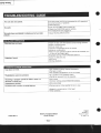
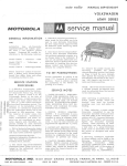
SPECIFICATIONS
CD playor seclion
Compactdisc digitalaudio system
System
Laser diode properlies lvaterial: GaAlAs
Wavelength:780nm
Emissionduration:Conlinuous
*
Laseroutpul: Max 0 4 mw
* This output is the value measuredat a distance
of about l.6mm lrom the obiective lens surtace
on the opticalPick'upblock
Frequencyresponse 20-20'000Hz1ldB
Radio s€ction
F r e q u e n c yr a n g e
Anlennas
FM: 87.6-1og MHz
MW: 530- l ,605 kHz
LW: 150-285 kHz
SW: 6-18 MHz
FM/SW: Telescopicantenna
MWLW: Builf in ferritebar antenna
Tage tecold€r sgclion and genetal
4'track 2€hannel stereo
Recording system
Approx. l.smin with Sony cassette C6O
i""t *inO-ini ti."
80- 10 000 H?
response
Frequency
Full-rangespeâkers:tocm dia ' cone type
Speakers
Tweeler:2cmdia.,ceramlclYæ
Peak music power outPut
22W(11W+1lW)
Line input jacks (phonojacks)-2
Sensitivity0.3V
Input impedance47 kilohmsor higher
Headphonesjack (stereo minijack)
Outputs
For 8-32ohms impedance headphones
CD output jacks (phono jack)-2
Load impedance l0kilohms or higher
Ratedoutput 1.4V rms at load impedance
47 kilohms
Power requirements 22O V AC, SO Hz
D C 1 2 V , 8 s i z eD ( R 2 0 ) b a t t e r i e s
Power consumPtron A C 4 0 W
8attery lile
Sony AlkalineAM1
Sony SUM.1(NS)
Batteries
FM recording
Approx.12
Approx.l7
Disc recording
Approx.3
Approx.3.5
(hour)
Dimensions
Weight
Supplied accessory
674 \221 x 177mm \w lhldl
(æ%x8%xTinches)
incl. poecting Parts and controls
6 . 2 k 9( 1 3 l b1 1 o z )
incl. batteraes
AC power cord (1)
DISG
COMPACT
TM/MTI'/LVSIï
CASSETTE.G
SONY.
SONY
AEP Model
MANIJAL
SERI|ICE
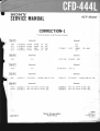
CORRECTION-1
Filethis correction-1
with the servicemanual.
(Correctl
(lncorrectl
c705
c711
c'112
c713
1-130483.00
1-130-483{0
1-124-963-11
1-r30.48300
lT"s"461
c795
5 % 50v
50Â 50v
20% 1 6 V
5 % 50v
none
none
1-124469-'t1
6.3V
{Correctl
À1-532439-21 L I NK , I C
(Correctl
1-249433-11 (RF BOARD). . . CAR8oN 100K 5% 1| 4W
1 -249433-11
(lncorrectl
(RF BOARD). . . CARBON22K 5y. 1t4W
{Correct}
1-237441-11 R E S , A D J , M E T A L G L A Z E
1-231442-1'l RÊS, ADJ, METAL GLAZE
22K
47K
1-230€95.11
RES, ADJ, MÊTAL GLAZE
1.230.608.11
RES, ADJ, MÊTAL GLAZE
Sony Corporation
9.952-980-91
20%
1.102-110-00CERAMTC220PF
(lncorrectl
lT"r"4tl
220MF
(Correct)
(lncorrect I
none
F"s-"48|
E LECT
none
(lncorrectl
RS701
RV701
RV702
O.O1MF
O.O1MF
33MF
O . OIlV F
none
I P"r"4-1
R70'l
MYLER
MYLER
ELECT
MYLER
Audio Group
20K
50K
Englidt
aaao547-1
Printedin Japan
@ 1 9 8 8 .1
sEcTroN1
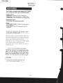
OUTLINE
Tho CFD"444is a casseilecorderequip@ wlth a FM/AM
luner, compact dlsc player,and lh€ separatospeakers.
CD player3octlon
. Repealplayto rep€atone or all ths selecÙons.
. Shuttloplayto ptaythe selectionsin randomorder.
oProgramplâyto playthe selectionsin a dosiredorder.
Caseettedeck sectlon
oSynchronlzcdCD æcodlng stad lyltem
General
. $band graphlcequallzerto adiustthe tone qualityto
your preference.
. Poworoutpul of 4W+4W (measur€d
at the FTC
regulation)
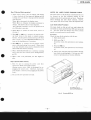
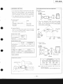
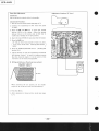
NOTES ON HANDLING THE OPTICAL PICK.
UP BLOCK OR BASE UNIT
The laser diode in the optical pick-up block may
suffer electrostatic breakdown because of the potential difference generated by the charged electrostatic
load, etc. on clothing and the human body.
During repair, pay attention to electrostatic breakdown and also use the procedure in the printed
matter which is included in the repair parts.
The flexible board is easily damaged and should be
handled with care.
S A F E T Y . R E L A l E DC O M P O N E NW
l A R N I N G!!
COMPONENTS
I O E N T I F I E DB Y S H A D I N GA N D M A R K
7\ orrr rxe scHEMATtc DIAGRAMS AND tN THE
PARTS LIST ARE CRITICAL TO SAFE OPERATION.
REPLACE THESE COMPONENTSWITH SONY PARTS
WHOSEPART NUMBERSAPPEAR AS SHOWN IN THIS
M A N U A L O R I N S U P P L E M E N TPSU B L I S H E DB Y S O N Y .
CAUTION
a use ot controtsor adjustmentsor pertormanceol
proceOuresolher than those specitjedhe.ein mav
re S u l l In h a za rd o L ,'sr adialr on er posur e
-2-
l"ro\
4t/
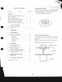
TABLE OF CONTENTS
Section
I
q+
Chuck Plate Jig for Repair
Title
Page
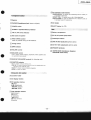
Specifications
Features
Notes on Handling The Optical Pick-up
Block or Base Unit
I
2
2
Chuck Plate Jig for Repair
Notes on Spindle Motor Repairing
Location and Function of Controls
S e r v i c e M o d e ( s e r v i c e p r o g r a m ). . . . .
n heck .......
N o t e so n L a s e rD i o d eE m i s s i o C
1.
BLOCK DIAGRAMS
l-l.
Radio/RecorderSection
J
4
6
7
8
9
1-2. CD Section
2.
DTSASSEMBLY
3.
ADJUSTMENTS
3-l .
Mechanical Adjustments
Electrical Adjustments
AM Section
FM Section
Recorder Section .
CD Section
Reference
3-2.
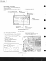
4.
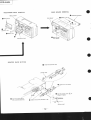
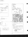
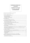
When repairing the CD section, use the chuck plate
jig in order to play a disc without using the CD cover.
Chuck plate jig part No.: X4918-255-l
Chuck plate jig component parts:
....11
l3
l4
14
l5
t7
l8
2l
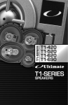
Noteson SpindleMotor Repairing
The spindlemotor (M702) used in this set is pressed
into turntable assy,but the repair parts âre suppûed
separately.
rfihen replacing,order both turntableassyand spindle
motor.
The installationdimensionis as shownbelow.
DIAGRAMS
4-1.
Radio/Recorder Section
Mounting Diagram
4-2. Radio/Recorder Section
Schematic Diagram
4 - 3 . C D S e c t i o nM o u n t i n g D i a g r a m
4-4.
4-5.
CD Section Schematic Diagram
IC Block Diagrams
5.
EXPLODEDVIEWS AND
PARTSLIST
6.
z5
25
28
JI
.....36
ELECTRICAP
L A R T SL I S T. . . . . . . . .
T r o u b l e s h o o tG
i ouni d e . .
........
42
50
19.4 x0. I mm
o
o
o
o
cFD-444L
I Page29,30 |
17
, correcred
porrion
I
tg
lttJ<o
ô-< I
I
*<6
cFp-444L
$'4q'SS\
tc704^, ,1 \
\
;\,it-trtm
t-
ICDLEAFSWBOARD)
rnalsurtol'tf
:RD______!1.,,"-.,.
cNJ-(.
, -l
l-tr] :-,
E ,E l<'Etui "'
*aoeJ-;;1
l1
lf4.";l
lJi[] l? L4.lr
I tÈil
>J'""'1-t;1";:ffi
lil l:ill<.liEir
l::l l:;lI l;ffi:o
Ç
E
-3-
__
tI_)l!
Ir
|
-.t
l ? A ouvogl8)
.IluIu!
|
_:'----------r
---]
+l:iilii:::,:j:jiir'i'i:':j'jjiii:i:i:::jiili'ji:iil:i:1:j'ji:ji'i:ii:':ji'jiji:j+1'1:'1:::1;;à;;''1ii$',ffijrjii'ii:
'^lalas
rol
lerulrs
-- --. .U
"'"
".
Ïi .c,,tnrtuo eceldeg
il",ri;-i'--q-+Ji'trJi-f..!,,,'Ë'
I
ffizt
uoluod pelcarlo. , Il
-9-
282'tâ20 gti?,t11'
izi\
dft6,:àtli
I l.*,iti3i
sllt
Itowæ-
:
:
!
I)JO
.lt"ji"
rr^0
i?:-cili;ciie
"-lnr
^ç-LJ
l_l
l.:
..
"-I
.. L_lT"ll_Jf
cFD-444L
23
22
21
Notr:
. Atl capacitors are in tlF unless otherwise noted. pFt rjpF
50WV or less are not indicated except for electrolytica
and tantalums.
All resistors are in O and %W or less unle$ otherwise
soecified.
i B+ bus.
: a d j u s t m e n tt o r r e p a i r .
f:
V o l l a g e s a r e d c w i l h r e s p e c tt o g r o u n d u n l e s so l h e r w i s e
Fati
L/u
U L .*',
noted.
o
.
Readings are taken
under
service mode
with
a VOM
(50 kç}/v ).
no mark: STOP
(
): PLAY
V o l t a g e v a r i a t ; o n sm a y b e n o t e d d u e t o n o f m a l p r o d u c
lton tolerances.
W a v e f o r m sa r e t a k e n t o g r o u n d i n s e r v i c em o o e D y u s r n ! ]
oscilloscope.
V o l t a g e v a r i ô t i o n sm a y b e n o t e d d u e t o n o r m a i p r o o u c
tion tolerance_
S
: C D s i g n a lp a t h
Switch
R€f. No,
s602
s701
s801
s802
s803
s804
s805
s806
s807
s808
s809
s810
Yzav---o
1;.1:'':-*E'
?BnArsa
n PAUST
sÊrR,cH
sroP
iErArn/Ex1€R
c302
cxP502aH0270
",/)'^""".,
aiiF;iiTtS
*,9.L,,"e
-6-
Swilch
MD pause
LIMIT IN
l<<
P6ition
OFF
OFF
OFF
UFF
>>l
REMAIN/ENTÉR
REPEAT 1/ALL
SHUFFLE/RMS
I
>/aa
CD HOLDER
OFF
OFF
OFF
OFF
OFF
OFF
ON
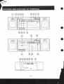
EICO op"rati* modebuttons
REMAINTENTER:
To disptaythe remainingtime od a disc. or
to programselections.
REPEAT I,ALL: To repeat one or all ot the selections.
SHUFFLE/RMS:To play the selêctions in a random order, or
to programspecific selections.
[Jspeater
jack (stereominijack)
@eXOleS fteadphones)
@Co trotoer
EPOWER switcfl
ElaeCr hdton(forCD)
indicator
EJOPR/BATT(operation/battery)
@fm Sf (FMsterco)indicator
@ Diatscateand pointsl
@AC lN (ACpower input)socket
EIFTNETUNtNcconrrol
Usedfor precisetuningof SW stations.
@ fefscopic ar ertna
@t-tl\|e lN 0ineinput)iacks(phonojacks)
@ Tuningcontrol
pAmo
@CO OUf 1COoutpur)jacks (phonojacks)
selector
@SPEAKERteminats
@votumeconrrot
E lSsrFMMODE(tnterf€r€ncêSuppress
SwitcfirFMmode switcù)
@BALltCe contot
Use to adjust stereo imaging,especiallywhen speakersare
not symmetricallyplaced.
(fortistening
controts
onty)
@cneexrc EouALlzER
selector
@FUNCT|ON
CD: To listen to/recordCD sound.
LINE lN: To listen to/recordsound trom the equiomentconnected to the LINE lN jacks.
RADIO:To listen to/recordradio programs.
TAPE:To listen to taoes.
CD,crorlbdcdrrreton
@ Cassetteholdsr
ECD displaywindow
ECO operationbuttons
I (stop)
>tl (play/pause)
<</>> (search)
(AMS)
l<</>l
@Tape operationbuttons
I (stop/eiect)
a (record)
> (playback)
<< (rewind)
>> (fastforward)
ll (pause)
-5-
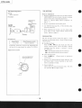
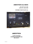
S E R V C I E M O D E ( s e r v i c eP r o g r a m )
This set has built-in service program in the microcomputer as usual sets.
The operation method of serviceprogram is explained
below.
[
] : Main operation in service mode
for details. rcfer to step 2.
.(sToP)
Be sure to set POWER switch ON,
lf not. key inpu$ can not be operctecl.
f Rewrn to the stand W mode"l
Land stop the display.
l
>II(PLAY/PAUSE)
fFocus servo goes on andl
Lturn to pull-in mode. J
'H H00H00
s
),> (FF)
f Opticatpick-upgoesto1
L outside circumference. J
REMAIN/ENTER
servoand sledf
f Tracking
)
Lservogo on,
<(FR)
fOpticalpick.upgoestol
Linside circumference.
J
Be sure to close CD holder.
lf not, key inputs can not be operated.
Fig. 1 Key Positions
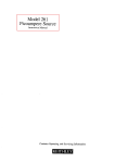
Step 1 (ServiceMode Setting Method)
Solder jumper for servicemode.
I Aftei chécking or adiusting in servicemode,\
/
\be sure to remove this solder iumper'
l. Turn the POWER switch ON and FUNCTION
switch to CD with the power cord not pluggedin
(no power appliedto set) and pressthe ) lf key.
(This is to dischargeC804 connectedto IC801
pin Q) (RSr).)
2. Solderjumper TEST point.
(IC801pin @ trrsrl is grounded.)
Plugin powercord.
This puts the set into servicemode.
- CD control
board -
\l l co
t-J
-
I
'L_r-
Fig. 2 TEST Point Position
-6-
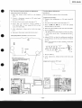
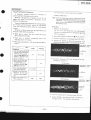
Step 2 {ServiceMode operation}
NOTES ON LASER DIODE EMISSION CHECK
l. When service mode is set, the display will change
6 times (includes âll the segments lighting and all
turning out), and those 6 changeswill be repeated
over and over.
When I key is pressed,the display stops.
When I key is released, the display continues to
change. This allows check of each segment.
The following operation can not be performed if
The laser beam on this model is concentrated so as to
be focused on the disc reflective surface by the
objective lens in the optical pick-up block. Therefore,
when checking the laser diode emission. observe.
from more than 30 cm away from the objective lens.
Laser Diode Check Procedu re
The laser diode on this set will not emit unless the
CD holder is closed and S8l0 (leaf SW type) is turned
on. The laser diode will always emit even if focus
search is not performed in servicemode.
the CD holder is not shut.
2. When I key is pressed on each mode, return to
the step l.
o
3. When })
or li{ key is pressed, the optical pickup block moves to the inside or outside circumference. Tracking servo and sled servo go off when
this is done, so press REMAIN/ENTER key to
turn on the tracking servo if necessary.
Procedure:
Check the laser diode emission with the eve.
l. Openupper panel.
2. S8l0 on asFig. 3.
(In service mode, this operation is not necessa-
rv.)
4. When )ll key is pressed, CLV-S (pull-in mode)
starts while performing focus search. When there
is no disc installed, focus search is repeated several
times while disc motor is rotating.
3. Pressthe )ll key.
(ln servicemode,this operationis not hecessary.)
5. When REMAINi ENTER key is pressed, tracking
servo, sled servo and CLV-A (servo during PLAY)
go oN.
4. Observethe objectivelensand confirm that the
laserdiodeis emitting light. If it doesnot, APC
circuit or opticalpick-up block is defective.
6. When 4 and 5 are performed, the disc begins to
play.
Step 3 (ServiceMode release)
l. First be sure to unplug the power cord then
remove the TEST point solder jumper.
(During service mode, C804 is discharged by unplugging the power cord. Therefore, microcomputer ICS0l is reset by next plugging in the power
cord.)
2. The set will now operated normally.
SetS8l0 going on
with a thin screwdriver.
Fig. 3 Turning 5810 on
-7
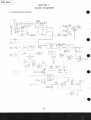
sEcTloN 1
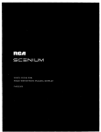
BLOCKDIAGRAMS
1.1. RADIO/RECORDERSECTION
s303'2
lïu voîËl1
D502
M0N0 _e
I
14
MWoSC
SI
RV2
IFmr-t
lBÂNoil
ITUNINGI
t
I
!l
l6 {Li{l
Ie
I
I
I7
rlz SWANT
SW
I
I
9ie
o
F V3O 6 R V3O7
uvE
lEÀL-ANcÈlltoL
HRP6OI
R E Cl P B
HEÀD
(
r,3,5,7,9
s':0,
sr:oz
fl
\
s30r
RECORD,/PLAYBACK
PLAYBACK
s302
FUN-rro-Nl
CD
I
t
s 3 0 r5
RECORD
s302-3
lFIoNÈal
L INE
I
RADO
I
-e
<Ja
s:o:.tffi
'l , ,
1
I
SI
EanDl
T]\r
I
2
-
R _ C H-
FM SECT ON
AM SECT ON
( Po0e10)
T 0 D 502
ta
SÂME AS L_CH
RAD O,TAPE SECT ON
l90l
s60l
TÀPEPOivER
PowER
ilE--n
lll cHsor
ill_+li{
P O W EARM PS E CITO N
D501
IôPR,€Àin
D R YB A Ï T .
s zE -c( I E CD E S G N A ITO NR I l N
8 P C S I, 2 V
I
-8-
o
J302
Àr N
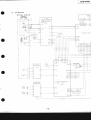
cFD-444L
1-2. CD SECTION
O P T I C A LP I C K - U P
BLOCK
KSS-1508
I 6 K BT F
tc6a
S G N A LP R O C E S S O R ,
L A S E RO N C R C UI T '
MI D P O N T V O L T À G E
GENERATER
!ETECTOR
f.
PD]
9-
1C701
, l3-l7
l-8, 1
29 32,3L-37
D B OI ' D B O 8
EFM
ASY
D I G I T A L S I G N A LP
L A S E RO l O D E
A U I O M A TC
CONTROL
POWÉR
-I
vc00
v c 0|
',
PD O
ri
CN N
OowÈ
>>>[:
NG
FOCUS/TRÀCK
C l ] L D RI V E
S W T C HI N G
s 70 l
LIMT
FOCUS
c 0r
CLOCK
LATCH
D A TA
RESET
SENSE
F O C U S / l R A C IKNG / S LE D l
CLVlPLL SERVO
SLED,/SPNDLE
DR VE
MOTOR
1C742
Ic107
M70l
StED
MOTOR
SLO
i./DP
MON
FSW
M7A2
SPNDLE
M OOTR
SPD L
-9-
x,r,.
:=:
CE
OE
WE
t2, 2
D/A
CONVERTER
1c705
D R ES S
8
LOUT
D A1 A
D A TA
e21o
BCLK
SCLK
_cH
0705
s v t/ l c H N G
: s s 0 R . c L v S E R VO
03
x701
1 6 9. 3 4 4N 2
0
M U TI N ô S WI T C H
8709,71A
f
;ËF
FOK
I
S UB O
s c0 R
TEST
CR C F
s30r-7
l. SMHr
R EC O R D ,/PLAYBÂC K
PLAYBACK
I
R ECO R D
-o 'q
(TEST)
''
WFCK
GFS
S Y S T E MC O N T R O L
Ic80r
START
0B0l
StJITCHING
s809
E
FE,/PIUSE
CLOCK
CLOCK
LATCH
LATCH
D A TA
DATA
SENSE
S EN S E
RESET
RESET
s808
SrnF
E
s8r0
CDHOLDER
MD PAUSE
s902
MDPAUSE
FF
SEARC
H
R E MA] N ,/E NTÊR
S H UF F L E T È Ms
o-a5
5V
/ s Y s l E M\
I C 0 N T R oI L
\ s E c T| 0 N /
-10-
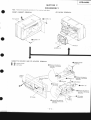
sEcTroN2
DISASSEMBLY
Noto: Follow the disassemblyprocedure in the numerical order given.
FRONT CABINET REMOVAL
CD BLOCK REMOVAL
VTPSx 14
q\
@ evres x ta
CD block
CASSETTE HOLDER A N D C D H O L D E R R E M O V A L
O-O:cassetteholder
O - (D r cD hotder
@ Remove the boss by
pushing in the arrow
direction.
\.\
Q Re-one the bols by
lD arpz.d , 6
-)r<.
'/
Gl cD cove,
e::!1i!.s in the arrow
dircction.
@ small damper
?-urrr"",,
:lt
@ Removethe bossby
pushing in the aûow
directionCD holder
up spring.
@ nemoré the bossby
pushing in the arrow
direction.
-1 1-
MAIN BOARD REMOVAL
MECHANISMDECK REMOVAL
O telescopicantenna
REC sw lever
O erps, to
OGEo boatd
.h
_o
Y 83x
BVTP3x 1O
@ eresx to
POTNTERRACK SETTING
lS tnstattthe Pointer rcck.
pointer rack
Q) lnstatt the TU chassis.
@ set thepointer rack @ as
shown in figure.
@ Turn tne tuning drumse'
f uII v coun tercIocKwt
x 1d
6 Tig;ên the screw IBVTP3
pointer rack
1O
cFD-444L
SECTION3
ADJUSTMENTS
3-1. MECHANICALADJUSTMENTS
PRECAUTION
t. Clean the following Parts with a denaturedalcohol-moistened swab:
pinch roller
record /plaYback head
rubber belts
erasehead
idlers
caPstan
Tape Path Adiustment
When the mode is playback (FWD, REV), run a
mi.rror cassette, then turn adjustment screw to
eliminate tape curl and tape twist at tape guide on
e r a s eh e a d a n d r e c o r d / p l a y b a c kh e a d .
Adjust the height by using head shim if needed.
S t a n d a r dt = 0 . 1
Part Cods
2. Dema.gnetize the record/playback head with a
head demagnetizer. (Do not bring the head demagnetizer close to the erasehead )
t
3 - 57 8 - 1 3 8 - 0 1
0.1
3 - 5 7 8 - 1 3 8I- 1
0.2
3 - 57 8 - 13 8 - 2 1
0.3
use a magnetized screwdriver for the
3. Do not
adjustments.
4. After the adjustments, apply suitable locking comp o u n d t o t h e P a r t sa d j u s t e d .
Torque Measurement
Torque
Torqug metal
Meter reading
FWD
cQ-102C
25 to 55 g'cm
(0.35to 0.?6 oz'inch)
FWD
BackTension
CQ{ O2C
2 . 5t o 5 . 5g ' c m
(0.04 to 0.07 oz'inch)
REV
cQ-102R8
25 to 55 g'cm
(0.35 to 0.76 oz'inch)
REV
BackTension
cQl02RB
2 . 2 t o 5 . 5g . c m
(0.04 to 0.07 oz'inch)
FF
cQ-2018
1 0 0t o 1 8 0g ' c m
( 1 . 3 9t o 2 . 5 o z i n c h )
REW
cQ-201B
9 5 t o 1 4 5g c m
( 1 . 3 3t o 2 . 0 1o z ' i n c h )
adjustment shim
-13-
cFD-444L
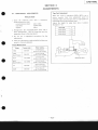
3-2. ELECTRICAL ADJUSTMENTS
MW/LW SECTION
FUNCTION: RADIO
BAND:
MW oT LW
AM rf signal
generatof
Put the lead-wire
anùenna close to
tne set.
30o ampl itude modulation
by 4O0 Hz signal
Output level: as low as possible
PHONES
. Repeat the procedures in each adjustment
several times, and the frequency coverage and
tracking adjustments should be finally done by
the trimmer capacitors
M W T R A C K I N GA T U U S T M E N T
Adjust for a maximum reading
on VTVM.
620kHz
I
1 , 4 0 0k H z
L3
|
CT1-3
M W F R E O U E N C YC O V E R A G E
ADJUSTMENT
Adjust for a maximum reading
on VTVM.
1 . 6 5 0k H z
|
5 2 5k H z
crl-4
|
T4
I
16/,@
MW I F A L I G N M Ê N T
Adjust for a maximum reading
ONVTVM.
4 5 5k H z
T2
n
MAIN BOARDI
rYr
l';El
-f|-
IS
LJ
- t( ât
L3
1 6 0k H z
|
,/
I E
tEr t I
cT2
cT4
|
T5
2 6 0k H z
2 9 5k H z
|
1 4 5k H z
Adjust for a maximum reading
on VTVM.
L W T R A C K I N GA D J U S T M E N T
Adjust for a maximum reading
on VTVM.
L W F R E O U E N C YC O V E R A G E
ADJUSTMENT
-14-
qpl
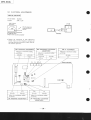
FM/SW SECTION
.
FM Section
FUNCTION: RADIO
BAND:
FM
Procedu
I
I
I
l@
FM rf signal
generator
l-
40O Hz. 30% FM modulation
frequency deviation !22.5 kHz
Output level: as low as possible
c.ri", r,"
I Modulatiol
I
I
FM antenna
an
input
.
SW Section
FUNCTION: RADIO
SW
BAND:
Output levl
,";::","
|
2. Adjust
|
symme
I
AM rf signal
gEnerator
I
S1/I'2TRACKING
Ouput
FM tf siC
genefator
ADJUSTMENT
level: as low as possible
L_
FM antenna input
H
s2a tE-l
headphones
FM TRACKING ADJUSTMENT
. Repeat the procedures in esch adjustmenf
several times, and the frequency coverage and
tracking adjustments should be finally done by
the trimmer caDacitors
1 8 . 4M H z
86.5 MH
Adjust for a maximum readir
on VTVM.
F M F R E O U E N C YC O V E R A
ADJUSTMENT
-15-
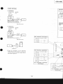
VCO Adiustment
ator Adiustment
A)
Regular Method
Procedure:
FM rf signal
generator
O.01pF
FM antenna input
PHONES
98 MHz
Carrier frequency:
Modulation:
Output level:
98 MHz
1 kHz, 30%
1 mV (60 dB)
1 kHz,75 kHz deviation (100%)
I mV (60 dB)
monoufal
FM antenna input
frequency counter
47pF
I MHz signal.
10 p.F/16 V
so that the oscilloscope waveform is
al.
l . Tune the set to 98 MHz
2. Adjust RVI for l9 kHz 10.2 kHz on the counter'
E
B)
Simple Method
Procedure:
l. Tune the set to the FM stereo broadcasting signal.
2. Turn RVI clockwise or counterclockwise and
memorize the lighting-up range of the FM
S T E R E O s t e r e ol a m P .
Adjust for a maximum reading
on VTVM.
3. Secure RVI at the center of the lighting-up range
of both turns asshown below.
center of lighting-up
FM IF ALIGNMENT
lighting-uP rangc
RVl
-1 6-
ranges
R E C O R D E RS E C T I O N
HeadAzimuth Adiustment
Record/Playback
l . T h e a d j u s t m e n t ss h o u l d b e p e r f o r m e d i n t h e o r d e r
given in the Seryice Manual. (As a general rule,
playback circuit adjustment should be completed
before performing recording circuit adjustment.)
Procedure:
l. Mode:playback
test tape
P.4.A063
(6.3 kHz, -10 dB)
VTVM
2. The adjustments should be performed for both
L-CH and R-CH unless otherwide indicâted.
.
o
Switchlocation
FUNCTION
ISS...
GRAPHIC EQUALIZER
BALANCE
VOLUME
PHONES
TAPE
2
2 . Turn
the adjustlnent screw and check output
peaks. If the peaks do not match for L-CH and
R-CH, turn the adjustment screw so that outputs
center click
c e n t e rc l i c k
mechanical center
S t a n d a r dR e c o r d :
Deliver the standard input signal level to the input
jack and set the REC LEVEL control to obtain
the standârd output signal level.
within
L.CH
peak
output 2 d B
level
I
I
Standard Input Level
LINE IN
Screw
position
10kç)
source impedance
R.CH
peak
L.CH
peak
0 . 3 1v ( - 8 d B )
input level
R.CH
peak
position
Standard Output Level
SP OUT
32a
3 . 2a
load impedance
output level
HEADPHONES
0 . 7 7 5V ( 0 d B )
0 . 2 sv (
3. PhaseCheck
Mode: playback
1 0d B )
test tape
P-4-A063
(6.3 kHz, -10 dBl
L.CH
Test Tâpe
oscil loscope
tl
Usêd fot
Type
Signal
P-4-A063
6 - 3k H z , - 1 0 d B
Azimuth Adjustment
ws48A
3 k H z ,0 d B
Tape Speed Adjustment
+
PHONES
AdjustmentLocation:
Scrgan patt€rn
@@ose
adjustment screw
in phase
45"
good
90",
135"
180' ,
wrong
Note: Finish the screw adjustment with a lurn in the
clockwise di.rection.
After the adjustmenl, lock the adjustment screw.
-17 -
l-p sEcrroN
1
Tape Speed Adiustment
Setting:
Mode: playback
Notes on Adjustment
1. Perform adjustments except for CD OUT LEVEL
ADJUSTMENT in servicemode. Be sure to release
servicemode after completing adjustment.
(Refer to "Service Mode (service program)" on
p a g e6 , 7 . )
Procedure:
speedchecker
LFM.3O
or
digital freguency
counter
testtape
ws-48A
B kHz,OdB)
2. Perform adjustments in the order given.
3 . U s e Y E D S - 18 d i s c ( p a r t N o . : 3 - 7 0 2 -l 0 l - 0 1) u n l e s s
otherwise indicated.
4. When repairing CD section, use the chuck plate
jig in order to play â disc without using the CD
h o l d e r . ( R e f e r t o p a g e3 . )
PHONES
PREPARATION
Put the set into service mode (see page 6, 7) and
perform the following checks. Repair if there are any
abnormalities.
Specification:
Speed checker
-1.5 to +27o
Digital frequonciy counter
2 , 9 5 5t o 3 , 0 6 0H z
.
Fre-quency difference between the beginning and
the end of the tape should be within l7o (30 Hz).
Sled Motor Check
Press the >}l , lC( keys and make sure that the
optical pick-up block moves smoothly, without
catching, from the inmost -> outmost -+ inmost
circumference.
>) : optical pick-up block moves outward
l*{ : optical pick-up block moves inward
Adjustment Locâtion
.
Focus Search Check
(Focus search is performed
key.
l. Press thelll
c o n t i n o u s l y .)
2. Observe the optical pick-up block objective lens
and check that it moves smotthly up and down
with no catching or noises.
3 . P r e s st h e r k e y .
Check that focus search operation stops. If it does
not, press the I key again, longer.
-18-
I "to-*ot
o
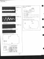
PLL FreeRun FrequencyCheckand Adiustment
Tracking Balance Adiustment
Check/Adjustment Procedure:
1. Short the jumper point (ASY) in the diagram
below.
Conditions:
The set should be placed either horizontally.
2. Connect a frequency counter to CD main board
test point TP (PLCK).
Adjustment Procedure:
l. Connect the oscillosocpe to CD main board TP
Put the set into servicemode (see page 6,7).
4 Check that the frequency counter reading is
4.375 !0.01 MHz. If not, adjust RV703 so that
it is 4.37510.01MHz.
5. After adjustment,releaseservicemode (seepage
6,7).
o
(TE).
2. Put the set into servicemode (seepage6,7).
3. Press the Dl and ll{ keys to move the optical
pick-upblockto the center.
Insert the disc (YEDS-I8) and close the CD holder.
5 . Pressthe )ll
key.
go from focus search to focus on, and
It
will
/
\
CLV pul-in mode state. Tracking and sled are
I
)
\ OFF.
/
6. Disconnectthe jumper point shortedin step l.
Check/AdjustmentLocâtion: CD main board
6. Adjust RV70l so that the oscilloscope wavefrom
'is
symmetricâl on the top and bottom in relation
to0 V.
Note: Take sweep time as long as Dossible to obtain best
waveform.
A__T-
o
1.5 to 25 Vp-p
t_J_
A=A
A= B
7 . Pressthe r key.
8 . After adjustment, release service mode (see page
SY solder iumper point
Short for checking and adiustment\
Disconnect after chæking and
I
adjustment
/
6,7).
AdjustmentLocâtion:RF board
o
t.--=--_
ll
tl
|
\-_=---]- _
+l
RV701
- CD main board -
frequency counter
o
-19-
"r""-* I
Adjustment Ldcation: RF board
FocusBiasAdjustment
Conditions:
The set shouldbe placedeitherhorizontally.
o
Adjustment Procedure:
l. Put the set into servicemode (seepage6,7).
2. Connect the oscilloscopeto RF board test point
TP (RF).
3. Press the ))l and lf{ keys to move the optical
pick-up block to the center. (Move the optical
pick-up block to the music area on the disc to
enableeasyvisibility of the eye pattem.)
4. Insertthe disc(YEDS-I8) and closethe CD holder.
5. Pressthe )ll key.
/ lt will go from focus searchto focus on. and \
pull-in mode state. Trackingand sledare I
{\ - CLV
t
\ OFF.
/
o
6. Pressthe REMAIN/ENTER button. (Trakingand
sledgo ON.)
7. Adjust RV702 so that the oscilloscopewaveform
eye pattern is good. A good eye pattern means
that the diamond shape( Q ) in the center of the
waveform can be clearly distinguished.
o RF SignalReferenceWaveform(eye pattern)
VOLT/DIV: 20OmV
TIME/DlV: 5OOnS
a
BF level
o
When observing the eye pattern, set the oscilloscope for AC range and raise vertical sensitivity.
8 . Pressthe ! key.
9 . After adjustment, release service mode (see page
6,7).
o
-20-
FocurÆracking Gain Adjustment
A frequency responce analyzer is necessary in
order to perform this adjustment exactly.
However, this gain has a margn, so even if it is
slightly off, there is no problem. Therefore. do
not
perform this adjustment.
Focus/tracking gain determines the pick_up
follow_
up (vertical and horizontal) relative
to mechanical
notse and mechanical shock when the
2_axis device
operate.
H o w e v e r , a s t h e s er e c i p r o c a t e ,t h e a d j u s t m e n t
is at
.
the point where both are satisfied.
o
When gain is raised, the noise when
the 2_axis
device operates increases.
a
When gain is lowered, mechanical shock
and
s k i p p i n go c c u r sm o r e e a s i l y .
o W h e n g a i n a d j u s t m e n ti s
off, the symptoms below
aPpear.
T h e f o l l o w i n g i s a s i m p l e a d j u s t m e n tm e t h o d .
- Primary Adjustment _
Noto: Sinceexactadjustmentcannotbe performed,
remem_
bej the positionsof the controlsbefoleperformins
the
adjusrment.If the positions
th";;i_;;;;;j;;;_
"ft",
ment ale only a little different,return the controls
to
the originalposition.
Procedure:
l. Keep the set horizontal.
the set is not horizontal, this adjustment\
/tf
c€nnot be performed due to the gravity
against I
I
\the 2 axis device.
I
2. Insert disc(yEDS-18) and press
b
u
t
t
o
n
.
)pLAy
3. Connect oscilloscope to
CD main board Tp (FE).
4. Adjustment RV705 so that
the waveform is as
shown in the figure below. (focus galn
adjustment)
VOLT/OI V: ,tOOmv
TIME/D|V: 2 mS
Gain
Symptomt
. The time until music slarts
becomes longer for STOp
-+ DPLAY
or automatic
selection (L<l tùlbuttons
pressed.) (Normally takes
about I seconds.)
Foqr3
l@mV
low
low
low focus gatn
VOLT/DI V: I O Om V
TIME/DIV: 2 m S
low or high
. Soundis interrupledduring PLAY. Or time counrer display stopsprogressing.
o Mole noise during 2.axis
device operation.
OV
low or high
a IncorrentExamples(DC level chaDges
more t h a n
on adjustedwaveform)
o Musicdoesnot startand
disccontinuesto rotate
for STOP--'DPLAYor
automaticselection.(
La
lùl buttonspressed.)
. Disc table opens shortly
afrer STOP--'>pLAy.
Trrcking
25OmV
Iow
OV
high
high
high focus gain
VOLT/DIV: f O O m V
TIME/DIV: 2 m S
5 . Coinect oscilloscopeto CD main
board Tp (TE).
o . Adjust RV704 so that
t h e w a v e f o r mi s a s s h o w n l n
t h e f i g u r e b e l o w . ( t r a c k i n gg a i n a d j u s t m e n t )
-21-
cFD-444L
CD OUT LevelAdiustment
VOLT/OIV: I V
TIME/DlV: 2 mS
Procedure:
CD OUT
1. Insertthe disc(YEDS-18).
(fundamental
waveappears)
a IncorrectExamples
2. Pressthe )ll keY.
low tracking gain
VOLT/DIV: 1V
TIME/DIV: 2 mS
OV
AdjustmentLocation: CD main board
high tracking gain
(higher fundamental wave than for low gain)
VOLT/DIV: I V
TIME/DIV: 2 mS
Adiustment Location: CD main board
---'-
3. Press the >)l key to play the second selection
( l k H z , 0d B ) .
4. Adjust RV706 so that the readingon VTVM is
1 . 3t o 1 . 4 6V ( 4 ' 5 t o 5 . 5 V r .
tracking gain adiustment
focus gain adiustment
-22-
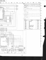
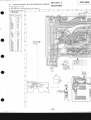
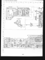
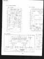
4-1. RADIO/RECORDERSECTIONMOUNTING DIAGRAM
.
.
Seepage27 for notes.
Seepage28 for SemiconduclorLead Layouts.
1
. SEMICONDUCTOR
LOCATION
Ref. No.
o1
D2
D3
D4
D30
D303
o302
D303
D501
D502
D90l
tcl
tc2
tc101
tc201
rc301
tc302
o1
02
ol ol
4102
420'l
0'202
o301
o302
o303
o304
0306
Locat io n
c-l4
c-14
c-14
c-'t4
E-13
c-7
D€
c€
r-15
t-15
t-6
2
SECTION4
DIAGRAMS
4
?
A
B
E-IJ
E-11
H.12
H-'t4
c4
El5
B€
F€
Èt-9
B-5
D€
D
o-7
D€
D-7
E
F
(,
H
I
K
-23-
5
6
7
I
10
11
JERMINALI
IEATTERY
12
13
14
15
16
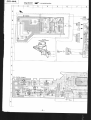
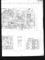
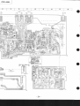
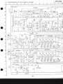
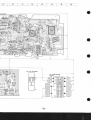
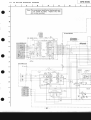
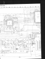
4.2. RADIO/RECORDERSECTIONSCHEMATICDIAGRAM
4
1
|laru BOARDI
tct TA?378P
ti
T E LA I ! T
FM 'ROIIT.TND
+
+
5t 4
d
laaar
@
I
I
I
il
0s c
ir
ii
I cvr-3
t- _-
0sc
I
i
Q| 2SC28390
il
5
t.5)
$l
ii
ti
0sc
I
-L-CH-
Qror2sc2458
,1
;ii--
J30lLo oui
J30r-2
Irflia'nl
BOARD(I/3)I
c0
tctot1A3600
I
c t 2 50,00r
roop
-R-CH-
tc20t 143600
ÂTIP
GRÂPNIC.EQUÂLI2TR
4 . 7/ 5 ( N
i E c o R Da M o
J30 3
6@
Jl0 -4
fai{ïtd
4225
RÉC0n0
/ PLAYEÂCr(
PLAYBÀCXl}R€CORD
llE601
130
330uH
'r301
c2t2
Erasosc
s30l_6
RECORO/PLAYOÀCX
P L A Y S A C+X N Ê C O R O
{,
q30r2sDl012
RECoRo
05C
-25-
F
I
L
I
cFD-444L
I
15
;.{
s r 7 t3Àr 0l
IGEABoAR0(t/3ll
c2 LAtSt0s
Q304
2SDr944
VOLt RÊG,
4t
t
aD76
0304 r
TuNrNGl
"'
TO
c Dt t^ r i 8 0 a n 0
Rl03
r00
(s':or
sPlo,
11
\
sl02-l
cD
[FïntTio r\']
1
Q1 0 2
2SC2458
LINE IN
1
1
RÂOIO
(sProJ
(sæor
IPOWER
BOARDI
(GEQ
(I/3)I
BOARD
Y-,,.
I
loiR/rÂri)
L__
0302R0e.lÊs-82
Dso-sLile,p
rI
D90l
sv4v820
I
RfCT
s90l
Fwrt
090r
cFD-rt44L
Not€ on Mounting DiEgrtm:
overthe end ot the iacket'
. Colorcodeor sleeving
Nota on Sch€matic Oiôgram:
. All capacitors are in pF unless otherwise noted pF: ppF
sOWV or less are not indicated except for electrolytics
and tantalums.
All tesistors are in O and 7.W or less unless olherwise
specified.
: fusible resistor.
@f
Switch with sliding contact indicated by hatched lines
shows shoning tYPe'
.
.
.
1^1
tl
-
.
B+ bus.
Voltaqes âre d(r wlth
.
ca-
a
a
I
a
i-i
r()specl to ground unless otnerwlse
: parts extracted Trom the component side'
: garts extracted from the conductor side'
: part mounted on the conductor side'
: indicates side identified with part number'
note o.
.
Readings
are
taken
Lrnder no signal conditions
with
a v o M ( 5 0k o / v ) .
no mark : FM mode
): AM mode
I
'
-:': TAPE mode
proouc
Voltdge variations may be noted due to normal
.
lion tolerances.
|
?>
: Flvl slgnai Path
C D s r qr r a l P a t h '
-,,' : TAPE siqnêl Patn
.
Switch
Rof. No.
s301
s302
s303
s601
s901
Po6ition
Switch
îl'"'il;ili
fi ;'#.;*;;;lt;iii;
ii
FM
playback
BAN D
Record/PlaYback
FUNCTION
ISS/FNI MODE
TAPE POWEB
POWER
CD
2lsT
OFF
OFF
;;';h;;;;';;i';;îi''':,
with ':::
A are critical for safety. Replaceonly
,,,, ,-,,,,,i'.
:f*iliîd;:::::r:
:::: :.r:::rr:::-::::r:
,1,,,,,,,,,,.,,,,,,,P,1I,,1T1!:1
CIRCUIT BOARDS LOCATION
main board
power sw board
fine tuning board
CD translation
board
GEA board
leaf sw board
power board
CD control board
RF board
CD main board
leaf board
-27-
cFD-444L
.
. SEMICONDUCT
LOCATION
Semiconductor Lead Layouts
cxP5024H-O27(l
8A5406
51
[
"À
5ll-o
ll
TM
-- J!8lXrffiffiÊi(
^^
gE
gÉ
'
*Ë'r[BB[!rtEr[[!88!B[r
æ,.
tn
I
19
BA6290A
e::==
a"
"-r
TTT-TIÏfiÏTII
| 23.56 r09
\12
t\ô\
cxA1081M
ffi
Jfiflrx$xrulx]
D701
D703
D703
D704
D705
D706
D701
D720
D798
ll-*
r20
H
2SA1048.GR
2SC634SP
2s,C2724C
25C28:t9.D
2SD1012
DTAl24ES
DTCl24ES
ï
s4v860
/'i\
D801
Dg02
D803
D804
D805
D806
Marking
Irr- |
/,'''-l
| . ."J/Â)
ïil
.Ï1
.{"\
I
ll-r-/'
-ll
2S81013
16
30
11DOO4
H2682L
1A737gP
33
tarta*
{1
tl
thÈ
LI
ffi
Ê
TI-
,l\
cxa1082AO
2æ2278
ân
L45005
6
cxA1083M
.Tllruiiuit
)t
T[TTn'[xTll'
It|l
LC3516AML-1s
tt
lltïl
,!ll
2SD1266.O
c701
c702
c703
c704
c705
c706
c707
c708
c709
c801
c802
0701
0702
0703
0704
0705
0706
4707
0708
0709
0710
0 7 11
o712
0801
0802
N
rril'
,' j-'.
"ra"t
*""
2SD1944
M51951BSL
/_'l
I (1
lTli
I l
/ iu,
M A q K N C5 D E V E I
CXDl l4OAM
20
r!
/fi.r.r.r.r.r.û\
)l
TnfiTnrf
M5218P
8765
lt|l
/*TT]T
l
1SS119
1SS133
Rl)6.8ES-82
RD8.2ES.B2
RD9.1ES.B2
RD11ES.B2
Noto:
a
t€-i!!r--*-___--l
l't'ïr-I
(Rto){(GrY))
L
v"-"'
tr
I
h--.*
\\
\ \ - - I|
|| $.-ql
's=77'
a c+
. .-_
a
-28-
C ol or c ode or s l eev i ng ov er t h e e n d o f r h e j a c k e t
:
:
:
I
I
parts
p
a r t se
r o m tI h e c o m p o n e n t s i d e .
extracted
x t r a c t e dtfrom
parts
r o m lI h e c o n d u c t o r s i d e .
o
a r t se
extrâcted
x t r â c t e dllrom
o a r l m o u n t e d o n t h e c o n d u c t o rs i d e .
i n d i c a t e ss i d e i d e n t i f i e dw i t h p a r l n u m b e r
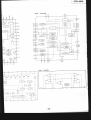
4-3. CD SECTIONMOUNTTNGDIAGRAM
?
XSS_ I50B
OPTICAL
PICK- U PBLOC K
uarl goanoa,-r
\r
{cNP2r
- - - . - + - - - 4 '
[CD CONTROL
sOARD)
t809
l;-m
I l '1 ?
L:J
|
29
o
o
o
o
o
-30-
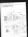
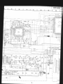
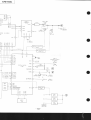
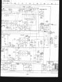
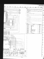
4.4. CD SECTIONSCHEMATICDIAGRAM
1
Note:The componen$identifiedby shadingand mark
A are critical for safety. Replaceonly with
part number specified.
t--
-31-
lnnn-aJ
I
I
0r r}tlrr|s
rrloàlf"'
ëia3i'É6ËËgÊ
srr/r'rrixis
0I,0- rirl,ossrJ
rrtrl/rrvirl
!!!s
!!!!t9
ranrr d
$nvd.7sa
riP
ri Èdl;e ;ÊÊlEpril:
NO
-J -,la\
rlo
J.J't
JJO
JJO
.t -l a\
JJO
Jlo
Jio
llo
uo!llsod
uf o-loH oc
ll/<
t
sri\tu/3"1JJnHS
"r-lv/r l_v:ld3u
U3IN3/NIVW3A
K<
DI
Nt lth '1
asnedol^t
qcr!rns
0 r8s
608S
808S
z08s
908S
908S
toSs
eoEs
z08s
roSs
rol.s
z09s
'oN 'leu
qcl!/t^s
-cnpord
q l e d t e u t j r sa t a : < 5
.acuerolol
uoll
leuroLl o] anp pêloit êq ^e L! su o tle t re ^ a6e t lo^
'adoJsolltcso
6ursn ^q êpor! ê:)r^tasut punoro o ) u ê )e l
a le sL! l o] ê ^eM
'sêJUPIêlot
-cnpold
uo!l
l e L u r o uo t a n p p ê l o u ê q ^ e L U s u o t t e u e ^ a 6 e l l o ^
^v-td :(
)
: àreurou
dO']LS
'(^/?Jl
09)
!\JO^ e q)rM êpoul a?r^rês .rêpun uê)et ere s6utpeêU
.
pêlou
a s r M / a q r os s a r u np u n o r '
o
r
r
l
.
a
d
s
ê
q]r^^
f,p
ale
sa6etlo^ .
. ) t e d a )r o 1
] u ê u r l s n f p e: E
o
snq+8:-.
'pa!l!ceds
esfMraqlo sselun ssel )o
M '/t pue u u! a.le stolslser llv .
'surnleluel pue
sJll^loJtcala ro} tdâcre paleJlpu! tou are ssâl ro
^MOg
'palou
âslMrâqto ssalun ln u! a.|e srollcedec
Jtttt :Jd
llv .
;9loN
ez
zz
oz
),2
zrrs
lLts
6t
8t
LL
1ùVn-AJC
cFD-444L
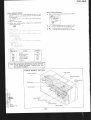
4-5. IC BLOCK DIAGRAMS
tc701 CXAl081M
v ac
L0 ol,l
f0(
TFM
LD
Â5Y
PO
O6ND
P0r
c8
CP
0 t F t cr
It
TRACXIN6
ERROR
AMP
F€ 8 I , A S
M OPOINT
VOLTAGI
8I.]FFER
o
rc?o5 cxD1140AM
tc707
cxA1083M
cFD-444L
XLT
MoN (
Mos (
DATA
XRST
^sv (
DIR C
vcorI
C .OUT
SINS
I SLI
ssiaP
sto
s-|
s ro
;
-35-
-----r--CFD-444L
I
sEcTtoN5
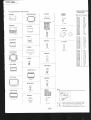
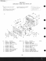
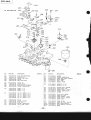
EXPLODEDVIEWS AND PARTS LIST
NOTT:
T h e r n e c h ô l | r c ôpl ô r t s w i ! h n o r e f e r e n c e
n u m b e rl n t h e e r p l o d e d v r e w s è r e n o t
s u p p Il e d .
' I t e m s m ô r k e d" * " ô r e n o t s t o c k e d s i n c e
they are seldom required for routine
s e r v i c e . S o m ed e l a y s h o u l d b e â n t i c i Pôtedwhenorderjng these items,
The construction parts of an assembled
part are indicated with a collation
n u m b e ri n t h e r e m a r k c o l u m n ,
(11
I
)
915
26
/D*24
\-F{zo
(
30
I
ilo.
1
?
4
5
6
7
I
9
l0
tt
!2
13
l4
t5
l6
18
Descri ption
-lq!_!!:
A-3235-537-AHOLDERASSY, CO
4-920-92?-01 TINOOI.I,CASSETÎE
A-3247-?74-A HOLDERASSY, CASSETTE
3 - 8 3 1 - 4 4 l - X XC U S H I O N
A-3241-738-ACABINET(FRONT
} SU8 ASSY
3-319-263-41 BUTTO}I
, POIIER
4-920-912-01 SPRING
*4-920-964-01 SPACER(C0 1)
3 -319-224- 3r DAÈPER
, SI'4ALL
4-920-907-01 BUTToI (C0 l|oDE)
't -685447-79
(+ PTp DIA.12 XH 3)
SCREX
(CDPLAY/ST0P
4-920-933-ll EUTTofi
)
(CDPLAY/SToP
4-920-933-01 BUTToN
)
(SEARCH)
4-920-906-01 BUTToN
4-920-902-0r KNoB(EJÊCT)
4-920-913-01 SPRING
Remô
rk s
No.
19
20
21
24
?5
26
28
29
30
31
Part No.
Descri pti on
*4-920-950-01 PLATE(C) , SHIETD
*4-920-955-0I RETAINER
4-920-914-01 covER(P) , c0
7-685-648-79 SCREI{,
TAPPING
7-685-649-79 scREll+8vTP3Xl4 TYPE2N-S
Remark
s
7 - 6 8 5 - 1 3 3 - 1 9scRErl+BÎP 2.6X6 TYPE2N-S
*4-920-945-01 LAEEL
(AE1)
I{UI'|BER
, MODEL
4-920-952-01 KIIOB( F.T)
4-920-968-01 STOPPER
3 - 8 3 1 - 4 4 l - X XCUSHION
, SPEAKÊR
9 0 7 * r - 6 2 2 - 77 I - 2 1 PC 80ARD,PoXER
5!
909 *L-622-773-tl PC BOARD
, CDCONTROL
*t-622-774-tL
910
PC EOARD,
COLEAFSII
915 *1-623-899-11 PC EOARI)
, FINE TUI.IING
-702-21
r,lD80l l-807
OISPLAY
PAI.IEL,
LTqUIDCRYSTAL
KEY)
s901 r-553-318-31 s r , l I T C HP,u s H( P o I E R ) ( 1
-36-
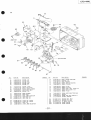
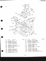
CFD-44'4L
t2l
901
60
\
*'sÉ
--rt---.
*(
o
74\/
&
l
84
63
MF-O/U4-75D
e_5'lK1
\J5e7e
o
81
tlo.
51
53
54
56
57
58
59
60
62
OJ
64
65
66
o,
68
69
Part No.
Descripti on
, S/E
3-319-530-01BUTTON
BUTTON
, REC
3-319-532-01 BUTTOII
, PLAY
T -1t O-(1? Jl l
BUTTON
, R€X
FF
3-319-534-0t BUTTOiI,
? -1 r o -(? I Jl I
Remarks
NO.
70
7L
72
74
Part No.
Descrlptl on
CAPACITOR
, TUNING
3-326-401-01 DRUI,I
T,. U
4-920-925-01 C H A S S I S
-01
RACK
4-920-927
, POII,ITER
4-920-908-01 LEVER,RECSI FU}ICTION
TAPPING
7-685-648-79 SCREII,
PAUSE
3-319-535-01 BUTTOII,
3-319-513-0I SHAFT,IO BUTTOTI
13-319-940-01 PLATE
, SHIELD,MOTOR
ASSY
x-3319-501-l EJECT
, SOFT
4-920-916-0I HOLOER
, LED
75
76
17
79
7-682-548-04 SCREI+B 3XB
7-621-259-35 scREt{+P 2.6X5
+BTP2.6X6 TYPE2I,I-S
SCRET
scREr+BVTT2.6X6 (S)
7 42t-259-45
7-682-144-01 scREll+P 3X3
)
4-920-929-01 KNOB(VOLUME
(CEQ)
4-920-918-01 K N O B
3-323-803-41 KTOB,BANDSELECTION
*4-9 20-9 17-01 HEATSIIIK (B)
*4-920-911-01 HEATSttIK (A)
80
81
83
84
7-685-649-i9 scREt{+BVTP3X14TYPÉz},1-S
3-701-443-11 l{AsHtR
+BTP3XIOTYPEzI'I.S
7 455447 -7 9 SCREI{
3-313-349-00 SPRING
, TENSION
*4-920.947-OTPLATE(A), SHIELD
* 4 - 9 2 0 - 9 5 1 - 0 1P L A T E
(B), SHIEL0
4-920-926-01 Kt{oB(TU)
4-920-928-01 LEVER,SAllDSELECTI0T'I
T6
PCB,MAIN
901 *A-3260-656-At"loUNTEo
PCB,GEQ
903 *A-3260-677-AMOUNTED
PC BoARD,LEAFSll
905 *t-622-167 -l!
D5ol 8-719-901-96 DI00EsLP1618
0502 8-719-901-96 DIoDESLPt6lB
-37-
Renarks
CFD-44.4L
(3t
911
113
--oæÀ9
,.,t
Tgl
lot
1>
t4
F901
f
I
F902
dq
t;
904
111
#.-t"
P
10
llo.
Part l|o.
Descri pti on
t0l
103
r04
r05
106
107
*4-920-948-01 P L A T E
(H}, SHIELD
4-920-954-01 FOOI,RUBBER
( REAR)
4-920-919-01 CABIIIET
3-319-528-91 HAIIOLE
(I,II}IUS},BATTERY
4-920-909-01 TERMII{AL
(C} , BATTERY
4-920-910-01 TIRMINAL
108
r09
3-319-916-51 LI0, SATTERY
CASE
+BVTP3Xl4 TYPEzN - S
7{85.-649-79 SCRÊI|
-79
pTP
(+
1485-647
SCRfl{
DtA.12 IH 1 l
+BVIP3X8
7-685{46-7t SCREI{
7{85-648-79 SCREI{,
TAPPIT{G
ll0
llt
t12
Remârls
No.
Part No.
Desc
rl ptlon
Remarts
+8 3X10
7-682-549-04 scREx
113
904 * l - 5 3 3 - r 8 9 - rr HOLDER,
FUSE
*
906
1 , - 6 2 2 - 12 7- 2 1 PC BOARO
, POTIER
t
908
ilAL
r-622-110-21 PC BOARD
TERJ'II
, BATÏERY
911
1 - 5 0 1 - 3 0 9 - 1 1ANTEI,INA,
TELESCOPIC
c 7 9 6 1-102-074-00 CERAI'|IC
0.00ur
F901 Âl-532-z
r5-oo.FUSE
' TIllg-LAG 80OnA
4902 Âl-$e-299-æ ÊusE, TltG.LAo 5À
T90l Â1-449-0$-rrTRANSFORIITR,
POIER
10x 50v
''::
, .. , , ' f t " . o . p o n " n t , i d " n t i f i " d
b / s h a d r r ' gd n d m ô r r / \ ô r e
crrllcal I0r 5a'ety.
c e p l ô C eo n l y w i t h p ô r t
numbe5
r p e c rf 1 e d .
-38
.':li
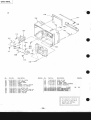
cFD-444L
(4)
16
I
.P
156
163
\\
't57
\{-K^ \ \
902
\
tffi
.ç,N
,,--.u'-*'u>'^'
151
't52
163 154
KSM.,'4OA
152
165
llo.
151
152
153
154
Part ilo.
0escrl ptl on
*x-4919-911-l C O V EARS S YC
, D
II,ISULATING
4-919-9 58-OI RUBBER,
3-679-164-00 SPRIIIG,TENSION
9-911-846-XXcusHI0l,l
r ç ( 14-921-128-01RETAIIIER,
BASE
156 14-919-952-01 BRACKET
BLOCK
157 * 4 - 9 2 0 -9 5 8 - 0 1 BRACKET,
(CO), SHIELD
158 14-919-970-01 PAPER
159
160
151
162
rk s
Rema
No,
163
164
165
166
,oescrl Ptlon
7-621-?59-3E scREr+BvrT2.6X5 (S)
+BVTP3X6 TYPEzIT-3
7-685-645-79 SCRETI
+P 2X6 TYPEzNON-SLIT
7-685-104-19 SCREI'
A.S)
4-920-967-01 S P A C E(R
Part No.
ASSY,llAltl, C0
902 *A-3216-372-APC SoARD
Ct) TRAIISLATION
9 1 6 * l - 6 2 3 - 1 6 9 - 1 1 PC BOARD,
0.011.tF
r-162-839-11 CEMMIC
ci88
0.001t4F
loz
c 7 9 0 1 -1 0 2 - 0 7 4 - 0 0c E R A tC4 t
14-921-135-01 F O I L ( F ) , S H I E L O
*4-921-131-01 F O I L ( O ) , S H I € L D
14-921-123-Ol F O I L ( B ) , S H I E L D
*4-914-828-11 PLATE, SHIELD
-39-
R€môr*s
CFD-4/,4L
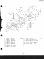
(5) MF-D444-75D
204 232
HRÆ01
2't2l
207
210
211
208
213
235
222
223
224
207
220
221.-
213
214
218
219
17
228
M60'
221
/
-3
l-l
Sll'l:>
t".l
vrel
rhlz
.,\\Jl
-\-\_]
230
iao.
Part No,
0escri ptl on
3-313-357{0 CLAI{, RECPRTVENTION
x-3313-311-1CHASSISASSY
3-334-7r7{1 B R A ( E T ( M ) , H E A D
3-313-339{0 SPRI NG
3-3r3-36r{0 ARM, ERASEHEAD
206 r3-332-309-O1S P R I N G( B )
207 3-307-948-01I{ASHER,NYLON
208 3-703-597-41PINCHROLL€R,STAIIDARO
209 3-313-340-O0SPRI }'IG, COI.IPRESSI
ON
201
202
203
204
205
210
3{78-138-O1
J-à/È'-IJ.'-I
I
3{78-r 38-2r
2ll
SEAM(t : 0. 1)
sEAfi(t : 0.2 )
(t =0.3)
SEAM
(t = 0. 1)
3-331-10841LUG(T) , SEAf.l
3-331-r08-1rLUG(T) , Str'r{(t : 0,2 )
3-33r-108-21L U G( T ) , S E A(Mt = 0 . 3 )
J.JJI-IUé-J.I,
L U G( T ) , S E A (r t. r= 0 . 4 )
3-33r-108-41LUG(T) ' Str't'l(t : 0. s )
2t2
213
?t4
2L5
2r5
3-313-316-00P U L L E Y
3-558-708-0lI{ASTIER,STOPPER
3-313-333{0 CLÂI.I,REEL
' OMPRESSION
3-313-344{0 S P R I N G C
3-313-305{0 T A B L E ,R E E L , S U P P L Y
Rema
rts
Descrl ptlon
No.
Part llo.
zLt
3-7 0t-437 -2r IIASHER
3-313-345{0 sPRI l,tc, CoMPRESSt0ll
x-333r-710-1 TAELEAsSY,RESL,TAKE-UP
3-558-620-11 GEAR'REtlI[O
7 - 6 7 1 - 1 1 2 - 1 1BALL' STEEL
3-307-948-41 I,IASHER,
TIYLON
218
?19
220
22L
222
223
:0.13)
3-701-438{t I I A S H (Et R
t : 0 , 2 5)
3-701-438-ll I A S H E(R
2?4
225
226
227
?28
x-3319-94s-1 BEARI
NGASSY,CAPSTÀN
x-3313-307{ PULLEY
ASSY,FID
x-3313-301-0 BRACKET
ASSY
, T PULLEY
3-573-464{0 SPRIiIG,COMPRESSIOII
3-313-902-11 S P R I N G
?29
230
231
232
x-3313-308-1
7-62r-?59-35
742r-2E5-35
3-324-22041
3-701-465{0
)71
PULLEY
ASSY,I.OTOR
scRfl{ +P 2.6X5
scRE[ ( 2r.ù,tx5
) , + PrH
S C R E(I 8I 2 . 6 ) , T A P P I N G
scREri,LocK
234
7-621-772-40 scREI +B 2X8
235
3-318-203-71 S C R E(I8{ 1 . 7 X 5 ) ,T À P P I N G
HE60l 8-658-O96-O2HEAD,ERASE
TBF5-36
HRP601
1-543-283-11 HEAD,I.IAGNETI
C (REC/PB)
l'1601 l-541-231-O0 l40T0R
-40-
Rg|tôrt s
cFD-444L
(6)
258
273
257
74 t2
zsa-4
276
278
79
FI'r.B
f',
3 zsq,.',
'-
l-fiu
,{, V-y/\
*'-Ar/{
251
283 28'l
Part No.
oescriPtion
LEVER(A) ' s'oFF
sPRlllc
H00(' SPRING
sPRt tlc' TENSIoN
sPRltlG'TENSI0N
NYLoN
l,lAsHER'
za o
3-313-32242
3-313-323{0
*3-332-31041
3-313-34840
3-313-349{0
3-307+48-41
?51
258
259
260
?6L
262
(E) ASSY
x-3592-309-1 FLYXHEEL
3-313-335{0 BÊLT'CAPSTAN
'i-iij-rer-zr
t UTToN
L E v E R( B ) , P A U s B
(St)' FR
3 - 3 1 3 - 3 1 4 - { 0L E V E R
3-313-313{0 sPRlfic
3-313-315{0 sPRING
251
25?
253
254
255
263
264
265
266
267
268
?69
' REll
x-3313-304{ ARMASSY
ING' TENSl0h
3-313-365-00 SPR
' FR
x-3313-312-I IoLERASSY
SToPPER
3-558-708{1 IIASHER'
*i-rrr-rsr-zt LEVER
' FFEuTTorl
3-313-356{0 BRAKE
*3-313-354-21 LEYER
' REX8UTToN
P a r tN o .
Remarks
Description
Renarks
' Fl,lo8uT10l{
LEVER
270 *3-313-326-21
LEVER'RECEUTTON
211 *3-313-350-21
LEVER'5T0P8UTTON
2 7 2 *3-313-325-21
LEVER'RCP
? 7 3 *3-313-320-11
' RFR
2 7 4 *3-313-321{0 LEVER'PREVENTiON
3-313-378{1 sPRmG(A)
275
276
277
218
279
280
28L
TENSIOI'I
3-313-343{0 SPRII'IG,
3-322-52941 SPRIG' TENSlotl
3-3 13-338-{0 SPRING
3-313-32i40 SPRING
' MECHAXICAL
ASSY
A-3i02-092-A CHASSIS
3-313-331-00SPRTNG
3-3r3-383-O1cLAr{(s) ' EJECT
282
' LOCK
283 * 3-313-352-11PLATE(B)
PLATE(A) ' LOCK
284 *3-313-351-11
L€VER
RETAINER'
245 *3-313-382-O1
7-687-233-11s c R E l(l + P T P I )I H( 2 . 6 x 6 )
286
POIERTENSIot'l)'TErlsIoil
3-341-181-01sPRING(
281
-41-
cFD-444L
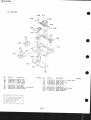
(7) KSM-140A
308
914
313
312
314
Part l{0.
301
302
303
305
306
307
308
309
Descri ptlon
x-2540-768-lG Ê A R( B ) A S S Y
x-2540-769-tGEAR(A} ASSY
x-2640-77
L-L TUR},ITABLE
ASSY
2-641-4r2-0r}IASHER,
RUBBER
*4-910-431-01 SHAFT,SLIDE
*2-611-434-0r COVER,
GEAR
2-64r-43 0-01 s c R E r( 2 . 6 X 6 ) , ( + ) K ÎAPPI NG
2-64I-438-01 HoLDER,
CHASSTS
'::.,..
.
T h e c o m p o n e n t .sd e n t i f r e d
b y s h a d rn 9 a n d - 6 r l
6rc
. , c r l t i c a l r o r s a t e t y ,. ,, f!i
' repjdce
only with pdrt
n u m b e rs p e c jf i p d .
-l
Remarks
Part No.
Desc
rl ptlon
310 3-303-809-31scREx
(M1.7X3,0)
, SPECTAL
HEAD
311 7421-255-15scREil+P 2X3
312 *x-2640-765-1cHÀsslsAssY,ilAlN
313 742r-255-25 scREt{
+P 2X4
314 7-621-77
L-06 scRE[+8 2X5
I
9 1 3 * l - 6 2 1 - 7 7 1 - 1 1 P c 8 o A R DR. F
914- ^a-848-078-01 prct(up, olrrcA. (rss-rsos)
r'r701 x-2640-770-l 0T0R(SLED)ASSY
t4702 l-541-352-11 0T0R( SpINDLE
)
l
Rg|rèrks
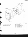
CFD-44,4L
353*=.-ù
(8)
357
353
351 (L-cH)
352(R-cH)
354
sPgo, lL-cH)
sP90E(R-CH)
353
912
h
f''
,.t
3 58
sP902 (L-CH)
sP904 (R-CH)
,fr'
I
I
I
F
r
I
t{o.
35t
352
353
354
Part o.
0escription
X-4920-903-1 BOXASSY (L) , SPEAKER
X-4920-902-l B O XA S S Y( R ) , S P E M E R
, SPÉAKER
3-831-441-XXCUSHIOII
14-920-915-01 L I D , R E A R S
, P
Remarks N o ,
Part No.
oescriPtion
3 - 3 3 1 - 5 2 3 - 0 1FOOT
355
TAPPING
7-685-648-79 SCREI{,
356
+BTP3XIOTYPEzN-S
i -685-647-79 SCREII
35i
9 - 9 1 1 - 8 3 7 - X XC U S H I O N'( AF)I L T E R
358
912
l - 5 5 6 - 6 5 0 - 0 0 C O R DS, P E A K E R
sP90l l-5?9-030-21 BUZZER
IOOFER
sP902 1-503-816-11 SPEAKER,
sP903 1-529-030-21 BUZZÊR
XOOFER
s P 9 0 4 1 - 5 0 3 - 8 1 6 - 1 1SPEAKER,
R€rna
rt s
CFD-4r',4L
sEcTtoN6
ELECTRICALPARTS LIST
NOTT:
' Items marked
* " a r e n o t s t o c k e ds i n c e
they are seldomrequired for routine
service. SOmd
e e l ô y S h o u l db e a n t j c i P d t e d w h e n o r d e r i n g t h e s e i t e m s.
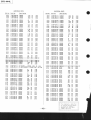
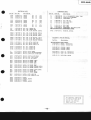
CAPACIlORS:
iilF:!F, PF:!}]F.
RESI STORS
' Al I resistors are in
ohns.
'F:
nonfa
l mmable
I f t h e r e è r e t w o o r m o r e s ô m ec i r c u i t s i n a
s e t s u c h ô s a s t e r e o p h o n i cm à c h i n e ,o n l y
t y p i c a l c i r c u i t p ô r t s m a yb e i n d j c ô t e da n d
c à p à C i t O r sa n d r e s i s t o r s i n O t h e r s ô m e
c i r c u i t s m a yb e o m i t t e d .
COILS
.MMH:mH,UH:!H
SEMICONDUCTORS
I n e a c hc a s e , U : u , for exômple:
U 4 . . .: u A . . . , u P A . . .: p P A . . . , U P C . . . :p P C ,
L J P o . . . p: P D . . .
ELECTRICAL
PARTS
Ref.No,
Pôrt llo.
ELECTRICAL
PARIS
Descrl ptl on
Ref.No. Pèrt No.
D e s c rD
l tlon
c33
c34
c35
1-124-927-ll EL€CT
1-162-?94-31CERAMIC
1 - 1 6 1 - 3 7 9 { 0 c E R ÂI C
4.7r,tF
0.00lMF
904
905
906
*A-3260-656-AltoU[TtDpCB, AIII
*A-3216-372-APC 804R0ASSI, IAIN,
CD
rA-3260-677-At0ul,tTEo
PcB, GEQ
* t - 5 3 3 - 1 8 9 - 1 1H o L o E RF, U S E
'L-622-767-lL PC B0AR0,LEAFSr{
* 1 - 6 2 2 - 1 1 0 - ? 1P C8 0 A R DP, 0 ! E R
c36
c37
c38
907
908
909
,1-622-771-21 PC 80AR0,Po|{ER
S}l
,1-622-772-21 PC BOARO,
BATTERY
TERMTNAL
,L422-773-M
C B0AR0,C0 CoNTROL
910
911
912
*t-622-774-LL pC SoARD,CDLEAFS[
l-501-309-u ANTE{NA,
TELÉSC0P
rC
l-556-650-00 coRD,SPEAKER
901
902
903
9 1 3 * 1 - 6 2 1 - 7 i t - l l P c B 0 A R 0R
,F
,14 A-8-8aE-O78{1 prcx{rp, opTrcAL(Xs6-1508}
*
1
6
2
3
8
9
9
l
l
p
c
915
B o A R DF, I N ET U N I N G
916 *1-623-169-u pc B0AR0,cD ÎRANSLATION
cl
c2
c3
1 - 1 6 2 - 2 9 4 - 3 1C E R A
IC
l-162-204-31 CERAMTC
1 - 1 6 2 - 1 9 5 - 3 1C E R A M I C
0,00lMF
I6PF
4.7PF
toc
5X
loc
50v
50V
50v
c4
c5
c6
t-162-294-31 C€RAMIC
1-161-379-00 CERAMIC
1-162-294-31 CERAMIC
0.00ltrtF
0.0lMF
0,00lMF
10x
30x
10?
50v
16V
50v
c7
c8
c9
1-162-203-31 CERAMTC
1-162-206-31 CÊRAMIC
1-162-196-31 CERAMIC
I5PF
zOPF
5&
50v
5%
50v
10% 50V
c10
c11
cL?
c13
l-161-379-00 CERAMIC
1 -1 6 1 - 0 5 5 - 0 0C E R A
TC
r-124-908-lt tLEcT
1-16l-052{0 CERAMIC
0.0lMF
0.02?t4F
22t4F
0.01zt'rF
30c
102
201
l0%
c14
c15
c16
r-16l-052-00 CERAMIC
1-161-043-00 cERAf,tIC
l-161-494-00 CERAfiIC
cLl
c18
c19
0.0lMF
20x
lox
30c
50v
50v
16V
1-102-113-00cERAMtC
1 -1 0 2 -l 1 l - 0 0 c t R A l t t c
l-161-047-00 cERAItC
39OPF
27OPF
0.004.7r,9
5X
10c
tox
50v
500v
25y
C39
c40
c41
1- 102-109-00 CERAIi|IC
1- 102-945-00CERAMTC
1-162-194-31CERAMIC
lBOPF
8PF
10% 50v
0.sPF 50v
loc
50v
c42
c43
c44
l-162-282-31 CERAMIC
1-161-055-00CERAMIC
l-162-294-31 CERAUIC
0.022MF
0.001t4F
c45
c46
c47
c48
c49
c50
c10l
cl02
cl03
l-162-294-31 CtRAMtC
l-162-199-31 CERAiiIC
1 -1 6 2 - ? 1 93-1 C E R A t 4 I C
l - 1 6 2 -I 9 9 - 3 1 C T R A M I C
1-102-943-00CERMIC
1 -l 3 l - 3 8 1 - 0 0 T A N T A L U I l
1-162-292-31CERAIC
1-123-875-11
ELECT
1-162-294-31CTRAIC
0.00lMF
IOPF
68PF
1 OP F
6PF
47t4F
68OPF
l0fiF
0.00l F
100Ê
IOOPF
10x
l0%
l0%
50v
50v
5Z
50v
50v
O . s P F 50v
202
10v
50v
2M
50v
LOX 50v
20x
10fl
loc
10v
25U
25V
16V
25V
25U
25v
c107
c108
c109
1-123-382-00ELECT
1-124-902-00ELECT
1-124-902-00ELECT
3.3MF
0.47MF
0.47MF
20fl
208
20%
50v
50V
50v
c1t0
clll
ctl2
l-124-927-ll ELECT
l - 1 3 0 - 7 7 0 - 0 0F t L M
1-161-042-00CERAMIC
4,7t4F
20&
0.1sMF
10c
0 . 0 0 1 8 M F 10r
0.01zt{F 10s
0.0022t,tF lox
0.022MF
25y
25y
25V
c113
c114
c115
l-162-294-31 CERAMIC 0 . 0 0 l M F
1 - 1 6 l - 0 2 0 - 1 1C E R M T C
0.03gMF
l-131-346-00 ELECT(
SOLID
) 0.68MF
loc
tor
20%
50v
25Y
25V
1-123-382-00 ELECT
1-124-499-11 ELECT
t-162-288-31 CERAMIC
3.3r4F
lMF
330PF
20&
20'
lm
50v
50v
50v
c 116
cr17
cltS
t-161-379-00 cÊRAl,tIc
0.0lMF
30c
1-131-343-00ELECT(
SOL
r0 ) o.22nF
20&
1-16l-377-00 CERAMIC
0.0047r'tF 30c
16V
25U
16Y
c20
c2l
c22
l-130-471-00 FILM
t-124-902-00 ELECT
l-124-464-11 ELECT
0.00lMF
0.47MF
o,22nF
10c
20r
20x
50v
50v
50v
cl19
c120
c12l
l-16l-021-11 CERÂMIC
1-162-294-31CERAI,iIC
l-t6l-494{D CERÀtitIC
c23
c24
c26
1-124-446-ll ELECT
l-r61-379-00 cERAMIC
1-162-284-31 CERAttIC
47Î'rF
O.OIMF
I50PF
20x
l0v
l6v
50v
c27
c28
c29
l - 1 6 2 - 2 0 13-1 C E R A M T C 12PF
1-162-560-ll CERAtlIC
0.047t'lF
r-124-604-00 ÉLECT
330ltF
c30
c31
1-162-560-u cERAf.tIc
1-161-379-00 cERAMIC
1-124-927-ll ELECT
0.047MF
0.0lMF
4.7 F
50v
63V
25U
0.047MF
0.00lMF
o.022ttF
lût
tox
25u
50v
25\
ct22 l-162-289-31CERAI.,IIC
c123 l-16l-329-00CERAMIC
ct24 t-124-9?7-rL ELECT
390PF
0.0068MF
4.7MF
loc
30s
2M
50v
l6v
50v
201
50v
l6v
t0v
cl25 1-t6l-039-00CERAI.IIC
c126 1-124-499-uELECÏ
c127 1-124-463-00ETECT
0.00lirF
lt4F
O.IMF
lox
20fl
20e
?51
50v
50v
30t
20&
l6v
l6v
50v
cl28 t-162-294-31CERAMIC
cL29 t-123-875-11ELECÏ
cl30 1-124-478-11
ELECT
0.00lr,rF
loc
20fr
20fr
50v
50v
25U
lor'rF
l00itF
{
50v
25V
50v
c 104 1-124-446-11ELECÎ
47MF
cl05
1-151-055-00CERAMIC
0.02?MF
C106 t-161-054-00 CERAT,,|IC 0 . 0 1 8 M F
!.ori
{
/
{
I
CFD.4A4L
PARTS
ELECTRICAL
PARTS
ELECTRICAT
Ref.llo. P.rt ilo.
Ref.ilo. Pôrt tlo.
Descrlptl on
D€scrlptlon
ELECT
c13l 1-124-360-00
c132 l-130-772{0 FILI.I
IC
cl33 L-162'282'31CERAI,I
-ll TLECT
cl34 L-124'927
c20t L-162-292-31cÉRAl,ttc
c202 t-123-875-1rELECT
1000,iF
0.22ttÊ
F
1OOP
20fl
10c
t0%
16V
63v
50v
c322 l-130-469{0 I'|YLAR
c390 L-t62-282-31 CERAMTC
c39l L-162-282-31CEM C
68OPF
IOOPF
l00PF
IOC
lM
lox
50v
50v
50v
4.7MF
680PF
tor'tF
20x
10t
20%
50v
50v
50v
c392
c393
c394
l-162-282-31 CERAI.IIC
L-162-282-31 CERA'.IIC
l-162-282-31 cERAr'ltc
IOOPF
IOOPF
l00PF
10?
10r
10x
50v
50v
50Y
c203 L-L62-294-3! CERAMIC
c204 l-124-446-11 ELECT
c205 l-161-055-O0 CERAMIC
0.00lMF
47r.tF
0.022MF
10r
20L
10,
50v
10v
25V
c206 1- 161-054-00 cERAt'llc
c207 r-123-382-00 ELECT
c208 l-124-902-00 ELECT
0.018r,1F
3.3MF
0.47t'tF
10%
20x
20fl
25Y
50v
50v
c395
c396
c397
c399
c601
ci01
c70l
20x 25\
22IIF
l-124-908-11ELECT
10c 50v
l00PF
l-162-282-31 cERA[lC
50v
10r
IOOPF
t-162-282-31CERAI.iIC
?5V
CERAIfIC o.o22l4F
1-161-494-00
25r
lon
0.011,ç
l-161-051-00CERAIC
(
R
F
0
.
0
0
2
2
t
4
t5fl 50v
.
C
É
R
Â
t
4
l
C
,
,
8oÂRD)..
l-130-475-00
0.ll'l|r l0x l6v
l-162-851-11(cD r,rAlr{B0AR0)...CÊRAMIC
. . .CERA{IC68PF 5l 50v
1-101-888-00(cD ltÂtil B0AR0)
} . . . . . . . . ELECT 33PFl0l l6v
l-124-963-00(RF BOARD
( c Dr,rÂrr,l
BoAR0)...ELECIlottF2 M 50v
1-r23-875-11
10%50Y
0'001t'tF
) . ,..,.. 'ELECT
t-t62-294 -31 ( R F B0^R0
l-123-875-11( c 0 [ A I [ B o A R D ) . . . E L E C T10f,tF 201 50v
1-124-443-00( R FB o A R o ) . . . . . . . . E 1 8 C Tt00NF 20x 50v
50Y
5X
O.OII{F
MYLAR
1-130-483-00
50V
5%
0.033t'lF
l-130-489-00ITYLAR
10c 3.15v
TAIITALUI.,I 1OOMF
1-131-392-00
50v
5t
0.033r
r,tYLAR
1-130-489-00
c2o9
c210
clll
r-124-902-00 ELECT
l-124-927'LL ELECT
1-130-770-00 FI LI.I
0.47MF
4.7t'rF
0. l5MF
20%
20%
lox
50v
50v
53V
c2t2
c213
c2L4
t-161-042-00 CERAMIC
,-'162-294-31CERAMIC
l-161-020-11 CTRAMIC
0.00181'tF 10%
t0%
0.00lMF
10%
0.039MF
25U
50v
25\
c?15
c?t6
c2L7
SOTID
) 0.68MF
l-131-346-00 ELECT(
0.0lî'lF
1-161-379-00 CERAI'IIC
S O L I)D0.zariF
l-131-343-00 E L T C( T
20%
30x
20%
25V
16Y
25U
c2l8
c2l9
c220
1-161-377-00 cERAt4lC
1-161-021-11 CERAMIC
l-L62-294-31 CERAMIC
0.0047MF 30%
10x
0.047MF
l0%
0.00lMF
16V
25V
50v
c22l
c222
c223
1-161-494-00 CERAMIC
1-162-289-31 CERAMIC
I-161-329-00 CERAI.IIC
0.02zMF
10x
390PF
0.0068MF 30x
25\
50v
16V
c224
c225
c226
ELÊCT
r-r24-927 -ll
1-161-039-00 CERAMIC
1-124-499-rI L L È L I
4.7r'tF
0.00ltlF
lMF
50v
20r
10% 25V
?ox 50v
c?27 1-124-463-00 ELECT
c228 1-162-294-31 CERAMIC
c229 l-123-875-11 ELECT
O.lMF
0.00111F
l0tlF
2W
t0%
20r
50v
50v
50v
c230 1-124-478-1rELECT
LLÈT,I
c231 1-124-360-00
c232 l-130-772{X) FIL}I
1001,l|F
1000MF
0.?2fç
2M
20L
10x
25V
16V
63V
CERAI,IIC
c233 L-t62-282-31
c234 bt24-927 -rL ELECT
c301 1-124-604-00 ELECT
F
1OOP
4.7MF
330f4F
10!
20t
20L
50v
50v
10v
c302 t-124-478-1r ELECT
c303 l-124-446-11 ELÊCT
c304 l-124-478-11 ELECT
l0oMF
47i.lF
100r,lF
201
20x
?0x
25U
lov
25\
47OMF
33OMF
0.0011,1F
0.0I|'rF
4i ot'rF
0.0lMF
2M
20r
tox
30x
?M
30r
25V
25V
50v
16V
I6Y
16V
c312 1-16l-379-00CERAMIC
c313 t-124-360{0ÊLECT
ELECT
c314 l-126-103-11
0.0ll,f
1000MF
47or,rF
30c
20e
20'
16V
16V
16V
c315 t-161-379{0CERAMIC
c316 1-16l-379-00CERAI'IIC
c317 r-124-472-lL ELECT
0.0lMF
0.0It'f
470 F
30s
30r
20%
16V
l6v
10v
2264F
?zUnF
0.0047tf
0.0056MF
20x
?o%
5L
5L
10v
lov
50V
50v
c305
c306
c307
c308
c309
c31l
c3r8
c3t9
c320
c321
l-124-480-11 ELECl
1-124-479-11 EL€CT
r-r62-294-31 cERt{IC
l-161-379'00CERAMIC
Et€CT
1-126-103-11
l-161-379{0cER^r,lIc
l-124-444-00ELECT
l-124-444-00ELECT
t-130-479-00MYLAR
I.tYLAR
1-130-480-00
cl02
cl02
c703
c703
c704
c704
c705
c706
c707
ci08
20150V
T
c709 l-124-463-00(coM A I I IE O A R D ) . . . E L E Co,lt'lF
5% 50V
R
c709 l-130-483-00( R F B 0 A R 0 ) . . . . . . . . M Y 1 4 0,011'tF
lo1 l6V
0.047MF
c710 1-162-847-11( c D[AI[ B0AR0).,cERAl,{lc
20t 16V
( R F B o À R D ) . . . . . . . E 1 É C33r'4F
T
c7l0 1-124-963-11
51
50v
O.OIMF
c71l l-130-483-00MYLAR
r6V
2M
33I,IF
ELECT
c7L2 1-124-963-11
50V
5%
O.OII'IF
c713 r-130-485-00MYLAR
10v
20x
?20$F
c722 1-124-444-00ELECT
20% l6v
0.01MF
cERAl.uC
c724 1-161-379-00
20% 50v
0.47tilF
c725 1-124-902-00ELECT
20fl 50v
lMF
ELECT
c726 1-124-499-11
20x 50v
1T
ELECT
c72'l 1-124-499-11
50v
O.OO47MF 5C
MYLAR
c128 1-130-479-00
t0% 50v
c729 l-162-294-31CERAMIC 0.0011'lF 2M
16V
33I4F
I ELECT
c730 1-124-963-l
201 50v
0.47t'lF
ELECT
c73r 1-124-902-00
50V
0.033MF 5%
c732 l-130-489-00 MYLAR
l6v
20x
33r,rF
È
L
L
L
I
1-124-963-11
c733
50V
0.0022[F 5S
c734 l-130-475-00I4YLAR
50v
0.047r,1F 51
MYLAR
c735 1-130-491-00
50V
5X
O.lHF
c736 r-136-165-00FI Llt
50v
5X
0.0331,1F
I'{YLAR
l-130-489-00
c731
50V
5X
0. lr4F
FI LM
c738 1-136-165-00
l6Y
20r
33Î'rF
ELECT
c739 1-124-963-11
10x 6,3Y
TA}ITALUt4 6 . 8 M F
c740 1-131-382-00
50v
5X
0.0681f
c74l l-130-493-00 I,IYLAR
10x 50v
47OPF
cl42 l-162-290-31CERAl.iIC
l6v
20t
33tF
ELECT
c?43 1-124-963-11
?5V
2U
2à1tF
c744 1-124-908-tt ELECT
20t- 10v
2?0/.1F
c746 l-124-444-00ELECT
50v
51
39PF
c747 l-102-965{0 C€RAf'lIC
50V
sfi
c748 l-102-961-00CERAI.IIC 27PF
50V
0.002zuF 51
c749 1-130-475{0 MYLAR
50Y
0.0022W 5t
c750 l-130-475-00I'/YLAR
-45-
ETEClRICALPARTS
Ref.No, Part No,
ELECTRICAL
PARTS
Descrlptl on
Ref.No. Part llo.
Descrlptl on
c751
c752
c755
l-124-442-00 ELECT
t- 124-442-00 ELECT
1 - 1 2 4 - 2 5 5 - 0 0ELECT
33OI'iF
33OI.IF
II'IF
201
20&
20x
6.3V
6.3V
50v
cNP6 *1-562-197-41 Housll{c,coN EcToR3P
cNP70l*1-564-706-l
I P I N , C O N I I E C T( S
OM
RA LTLY P E 4) P
(SMALL
cilP702*l-564-706-t
I PIN, COII}IÊCTOR
TYPE)4P
c756
c757
c759
1 - 1 2 4 - 4 9 9 - 1 1ELECT
I-L24-242-OO €IECT
1 - 1 2 4 - 2 4 5 - 0 0E L E C T
lMF
33MF
4.7MF
20%
20r
201
50v
i6v
l6V
cilP704*l-564-704-l
I P I N , C O I I N E C T( S
OM
R A LTLY P E 2
)P
orP706*1-564-727-l
(SMALL
I PIN, COiI}.IECTOR
TYPE}1lP
cNP708*l-564-337-00PIN, CONIIECTOR
3P
c760
c76r
c762
1-t24-927-lt
ELECT
1-124-443-00 ELECT
1-130-472-00M Y L A R
4.7MF
20%
IOOI4F
20%
O .O O 1 2 M F 5%
50v
10v
50V
c763
c764
c765
l-130-472-O0 YLAR
1-124-255-00 ELECT
1-124-499-11 EL€CT
0.0012r,rF 5%
IMF
20%
lMF
20fl
50V
50v
50v
c766
c767
c768
t-124-443-00 ÉLECT
1-124-902-00 ELECT
l - 1 2 3 - 8 7 5 - l l ELECT
]OOMF
O.47I4F
IOHF
20x
201
20fl
iov
50V
50v
c769
c770
c772
1-130-479-00 MYLAR
1-130-483-00MYLAR
1-130-483-00 MYLAR
O.OO47MF 5%
O.OIMF
5&
O.O1MF
5&
50v
50v
50v
cTl
c v 1)
r-rsr-rez+oCAP, TUNII,IG,POLYETHYLTIIE
8 - 7r 9 - 9 1 1 1
- 9 0t008lssl 19
8 - 7 1 9 - 9 1 l - 1 9 D I o D El S S l 1 9
8 - 7 1 9 - 9 1 1 - 1 9D I 0 0 El s s t 1 9
8-719-109-97 D I O D E
RD6.8ES-82
$rP709*l-564-34l- 11 Pm, coNilEcÎoR
7P
-503-l1 P I N , C o N [ Ê C T 9
cNP710*t-506
oP
R
cltP805*
l-564-718-lI PIII, CONNECTOR
(SMALL
TYPÊ}2P
ct{P808r1-564-337-O0
P I N , C o I | E C T o3RP
cllP809*l-564-341-11P I N , C O N N E C T
OR
7P
$lP8l0*l-506-503-II PIII, COIINECTOR
9P
cI2
l - 1 4 1 - 2 4 5 - 0C
0 A P ,T RI M I 4 E RC,E R A M I C
cT3
l - 1 4 1 - 2 9 0 - l r CAP,VARFILI.ITRI I.I.iER
cT4
1 - 1 4 l - 2 4 5 - 0 0 cAP, TRI t4t1E
R, CERAIItC
cTs
1 -1 4 1 - 3 0 4 - 2 1CAP,TRIt'IIi1ER,
CERAfiIC
c7-73 1-124-473-ll ELECT
c774 L-124-472-1I ELÉCT
c775 1-124-473-lI ELECT
1OOOI4F
47OMF
1OOOMF
20fr
20%
20e
10v
10v
10v
0l
D2
030
0301
c776
c777
c778
l-162-294-3! CERAIiIIC
l-124-444-00 ELECT
1-L24-412-1L ELECT
0.00114F
22OI4F
47OI'IF
t0%
20e
20%
50v
10v
10v
0 3 0 2 8 - 7 1 9 - 1 1 0 - 1 3O I O D E
R D 9I.E S - 8 2
0303 a-7'9-!to-22 D I O D E
RDlIES-82
0501 8-719-901-96 D I O O E
SLP1618
c779
c780
c781
L-162-294-31 CERAMIC
t - 1 6 1 - 3 7 9 - 0 0CERAMIC
1-162-294-31 CERAMIC
O.OO1MF
0.0It'1F
O.OOlI4F
10% 50V
20x l6v
LOl 50V
c782
c783
c785
1-r24-893-11 ELECT
22OOI4F
20x 10v
1-131-386-00 TANTALUM 33MF
10% 6.3V
1-102-074-00 CERAMIC
0.0011'4F 5Z
50V
0703
0704
0705
c788
c789
c790
l-162-839-11 CERAMIC
1-102-074-00 cERAl"tIC
1-102-074-00 CERAMIC
O.OIMF
0.00lMF
O.OO1MF
LOX 50V
lox 50v
0706 8 - 7 1 9 - 9 0 1 - 3 3D r o D E1 5 S 1 3 3
0 70 7 8-719-901-33 D l 0 0 E1 s s 1 3 3
D7?O 8-719-901-33 D I 0 D E1 S S 1 3 3
c79l
c792
c793
1-t62-294-31 CERAMIC
l-162-294-31 CERAMIC
1-162-851-11 CERAMIC
0.0011'lF
O,OOIMF
O.IMF
l0r
102
lox
50v
50v
l6v
D798 8-719-901-33 D I o D E1 5 S l 3 3
D799 8-719-901-33 D r 0 0 E1 s s l 3 3
0 8 0 1 8-719-9r1-19 D r o D tl s s l 1 9
c794
c796
c799
1-162-851-11 cERAtiIC
1-102-074{0 CERAI,IIC
1-162-835-11 CERAT4IC
0.lr,tF
0.001t1F
0.0047MF
tox
lox
lot
l6v
50v
16v
c801
c802
c803
1-102-965-00 CERAI.IIC
1-102-965-00 CERAMIC
1-124-465-00 ELECT
39PF
39PF
O.4?IIF
57.
5X.
20&
50V
50v
50v
c804
c805
c8t0
l-161-377-O0 CERAT'IIC
1-161-377-00 cÉRÂrltc
r-123-306{0 ELECT
0.0047MF 309
0.0047IrF 30x
47tttF
20x
l6v
16V
10v
c850
c90l
c902
l-161-772-11 CERAI.{C
l-101-004-00 ctRAM!c
l-101-004-00 cERAMtc
O.lMF
0.0lMF
0.0lMF
c903 l-101-004-00 CERAMIC
0.0lMF
c904 t-124-564-11 ELECT
4700r4F
c*90r ' ô. i.9?6:8a 2',1l:r rllllrÉT;..{d rÂt
cFl
t - 5 6 i - 1 9 8 - 7 1 F T L T E RC, E R A M I C
cF80l 1-527-932-00 oSCILLAToR,
CERAT4IC
10% 25V
50v
50v
201
50v
25V
0502 8-719-901-96 D I O O E
SLP16IB
D701 8-719-200-29 D I o D El 1 D Q 0 4
0702 8-719-200-29 DIoDE110Q04
D802 8 - 7 1 9 - 9 l t - 1 9 0 t o D El s s l 1 9
0803 8 - 7 1 9 - 9 1 1 - 1 90 r 0 D El s s l l 9
0804 8 - 7 1 9 - 9 1 1 - 1 9D I 0 0 El S S ll 9
0805
0806
D90l
-46-
8-719-911-19 0r00E lss119
8-719-9r1-19 0t00E lssl19
8-719-504-60 0toDE 54vB60
FLI
r-86422-tl
FILTER
, BANDPASS
F1701 l-235-984-ll F I L l E R ,L O I P A S S
F1702 l-235-984-1r FILTER,LO}IPASS
HE60l 8-558-096-02 I]EAO
EBF5-36
, ERASE
HRP60Il-543-283-11 HEAD,MAGI{ETI
C (REC/P8)
rcl
tcz
ICt0l
cNPl *1-564-508-11 ptUG,C0NNECToR
5p
c N P 2 * l - 5 6 4 - 5 1 I - n P L U GC
, 0 N N E C Î8opR
*
1
5
6
4
5
0
7
1
1
cNP3
P L U GC
, o N N E C T4opR
8-719-200-29 0IoDE 110Q04
8-719-200-29 D r o D Eu 0 Q 0 4
8-719-910-65 O I O D E
HZ6BzL
8-759-208-99 IC TA7378P
8-759-804-97 I C L A l 8 1 0 S
8-759-801-23 IC 1A3600
cFD-444L
PARTS
ELECTRICAL
PARTS
ELECTRICAL
R e f .N o . P a r t N o .
Ref.No. Part No.
D e s c rpl t l o n
o € s c r lD t l o n
Q80l
q802
2S01266{
8-729-400-81 TRAISlSToR
DTAI24ES
8-729-900-63 TRANSISToR
DTCI24ES
8-729-900-36 TRANSISToR
R1
R2
R3
l-249-417-ll CARBoN
t-249-400-ll cARBoil
1-249-410-1t CAR80
lK
39
270
R4
R5
R6
1-249-441-11CAR80N
l-249-424-11 CAREoll
1-249-432-11CARBoN
10( 5t
3.9K 5t
l8K 5X
t/ 4,1
Ll4v
1/4[
R7
R8
R9
t-249-441-ll CÂR80tl
1-215-454-00 CARBoN
-11 CARBotl
1-?49-417
100( 5?
24K 5C
5X
lK
r/4r
t/4t
Rl0
R11
R12
1-249-417-11 CAR80l{
1-249-406-11 CARBoN
r-249-429-11 CARBoN
IK
120
t0K
R13
R14
Rl5
R16
R17
R18
Rl9
l-249-429-lL CÂRBON
CARBON
l-249-427-n
l-249-427 -11 CARBON
1-249-424-11 CAREON
L-249-424-ll cÀR80N
1 - 2 4 9 - 4 3 3 - 1 1CARBON
1':249-441-i1 CARBON
lfr
6 .8K
6.8K
B.2K
3.9(
22K
l00K
R20
R21
R22
t-247-881-00 CARSON
l - 2 4 9 - 4 1 2 - 1 1 CAREON
t-249-417-11 CARBON
120( 5X
390
5&
IK
I/4tl
1/4ll
1/4f
R23
R24
R25
R26
R27
R10l
Rt02
l-247-883-00 CARBON
l-249-409-11 CARBON
1 - 2 4 9 - 4 4 11 1- CARBON
1 - 2 4 9 - 4 1 17 1- CAREON
1-249-393-ll CAREON
l - 2 4 9 - 4 0 5 - 1 1 CARBON
1-247-881-00 CARBON
15(X 5X
220
100K
5Z
1K
l0
100 51
120K 5X
Ll4v
1/4X
1 /4 W
l/4tt
v4tl
t/4,1
I /4V
R103 L-249-423-rl CAREON
R104 t-249-411-11 CARBON
R 1 0 5 1 - 2 4 9 - 4 1 9 - 1 1CARBON
3 .3K
Ll4,û
1 . 5 K 5X
t/4|
R106 I-249-429-rL CAREON
R107 1-247-849-00 CARBON
CARBON
R108 t-?49-425-ll
10K
5 ,6K
4.7K
R109 1-247-895-00 CARBON
R1l0 1-249-404-00 CARBON
l-249-429-LL CARBON
Rl1l
470(
a2
10|( 5%
L/4tl
U4',t
U4tl
2SCz839-0
8-729-883-9r TRANSTSToR
Qr
25C2724-C
8-729472-42 TRANSISToR
Q2
2SC634SP
Q101 8-129400-?7 TRANSISTOR
R112 1-249-407-11 CARBON
R113 1-e49-385-11 CARBON
Rl14 1-249-406-11 CAREON
150
2.2
t20
5&
5Z
Ll4t
t/41
I /4r,r
2SC634SP
I STOR.
Q l 0 2 8-7 29-600-?7 TRANS
25C634SP
Q 2 0 1 8-729400-27 TRANSISTOR
2SC634SP
Q2O2 8-729-600-27 TRANSISTOR
Rl15
R1t6
R117
l - 2 4 9 - 4 3 7 - 1 1 CARBON
L-249-427-Ll CAREON
cARB0r,l
t-249-429-ll
47K 5X
6 . 8 K 5Z
5X
lfr
Ll4U
l/4t{
t/41
zSDIO12
Q 3 0 1 8-729411-24 TRANSISTOR
2SDI944
Q302 8-729-905-66 ÎRANSISTOR
2SDI944
Q303 8-729-905-66 TRANSISTOR
2SDI944
Q304 8-729-905-66 TRANSISTOR
2SAIO48-GR
Q3o6 8-729-20443 TRANSISTOR
Q70l 8-729-801-83 T R A N S I S T2OSR8 I O 1 3
R1t9
R120
Rl21
l-249-424-IL CARBOTI
L-249-423-lL CARBON
l - 2 4 9 - 4 1 8 - 1 r CARBON
3 . 9 K 5X
3 . 3 K ST
1 . 2 K 5T
Ll4u
I l4t
t/4v
'R122
Rt23
R124
t-249-433-11 CAREON
1-249-409-lI CARBON
CARBOII
L-249-429-n
5X
2
220 5t
l0K 5X
L/4v
L/4\l
Ll4t
DTCl24ES
Q702 8-729-900-36 TRANSISToR
DTCl24ES
Q 7 0 3 B-729-900-36IRANSlSToR
2S41048-GR
Q704 8-729-204-83 TRANSISToR
R201 1-249-405-11 CARBON
R202 1-247-881-qo CARBON
cARE0ll
R203 t-?49-423-lr
100 sfr
12( 5L
3.3K 5t
1/4x
L l4tl
l/4r{
2SA1O48-GR
Q7o5 B-729-204-83 TRANSISTOR
Q7o6 8-129-322-78 T R A N S I S T 0 R ' 2 S C 2 2 7 8
C2278
Q707 8-729-322-78 T R A N S I S T2OSR
CARBoi{
R?04 1-249-411-11
R205 1-249-419-ll cARBotl
R206 l-249-429-11CARBorl
330 5r"
1.5K 5X
5X
1(
l/4t{
U4U
l/4r{
Q7r2
I C 2 0 1 8 - 7 5 9 - 8 0 1 - 2 3l c 1A3600
IC301 8-759-800-66 t c L A 3 1 6 1
tc302 8-159-942-22 t c 8A5406
8 - 7 5 2 - 0 3 0 - 9 3l c c xA108Ifl
8 - 7 5 2 - 0 3 1 - 6 1t c cxAl082AQ
IC70l
tc702
rc703 8-752-322-32 I C c x D l l 3 0 Q
tc704 8-759-802-74 I C L C 3 5 1 6 A M L - 1 5
IC705 8-752-323-88 I C cxD11404r.,t
IC706 8-759-601-02 l c M5218P
rc707 8-759-924-58 I C cxA1083M
t c 7 0 8 8 - 7 5 9 - 9 4 5 - 7 0t c 8A629OA
rc709 8-759-803-46 t c 1A5005
IC801 8-759-605-05 tc r'ts19518S1
r c 8 0 2 8 - 7 5 2 - 8 0 2 - 1 7rc cxP5024H-027Q
1 - 5 6 3 - 9 9 2 - 1 1J A C K , P I N 4 P ( L I N E I N / C D O U T )
l - 5 6 3 - 6 4 9 - 1 1 JACK (PHOI'IES)
1 - 5 3 6 - 7 0 5 - 2 1TERMINALBOARO(SPEA(ER)
J301
J302
J303
Li
L2
L3
*r-422-273-11 C O I L, A I R - C O R E
* t - 4 2 2 - 2 7L - r r C O I L , A I R { O R E
(}lI.I/LI,i)
t - 4 0 2 - 3 0 8 - 1 1ANTENNA,FERRITE-ROO
47OUH
Ll0r
l-408-429-O0 MICROINDUCTOR
47OUH
L20l 1-408-429-00 I'4ICROINDUCTOR
L3 0 1 1 - 4 0 8 - 0 9 2 - 0 0M I C R OI N O U C T O3R3 0 U H
22OUH
t 7 0 1 1 - 4 1 0 - 3 3 6 - 1 1I4ICROINDUCTOR
L702
1703
1704
22OUH
1 - 4 i 0 - 3 3 6 - 1 1 MICROINDUCTOR
22OUH
1 - 4 1 0 - 3 3 6 - 1 1I4ICROINDUCTOR
33UH
l-408-569-00 14tcRotNDUCToR
1705
1706
1707
1-408-557-00 M I C R OI N D U C T O3R. 3 U H
.3UH
l-408-557-O0 M I C R OI N O U C T O3R
3.3UH
l-408-557-00 fitcR0tNoucToR
1708
1709
1710
}
l-459-691-11 COIL (I,IITHCORE
1 - 4 5 9 - 6 9 1 - 1 ICOIL (}IITH CORE)
(
X
I
I
H
C O R)E
l - 4 5 9 - 6 9 1 - 1 1C O I L
M601 1-541-231-00 MOTOR
ASSY (SLED)
1 r 7 0 1 X - 2 6 4 0 - i 7 0 - I I4OTOR
(spIfiDLE)
w02
1-541-352-11 l'toToR
irD80l 1-807-702-21 D I S P L APYA N E LL,I Q U I DC R Y S T A L
P S 3r0a l - 5 3 2 - 8 4 21- 1 L I N K , I C( 2 A )
Q708
Q709
Q710
Q71l
DTCl24ES
8-729-9oo-36 TRANSISTOR
DTC
I24ES
8-729-900-36 TRANSISTOR
DTAl24ES
STOR
8-729-900-63 TRAI.ISI
2SD1944
8-729-905-66 TRASTSToR
:
5X
5C
5X
5X
5X
5X
L/4t
v4t
Ll4tl
I l4tl
| /4$
v4u
I lAtl
t/4u
5%
5%
l/41
l/4f
5%
| /4t
5X
5r
sfl
r/4u
u4u
v4t
r/4x
1/4\t
I/4
t/4u
I h e c o n p o n e n t 5l d e n t i f r e d
oy shadn
r g and.drl ^ôre
, : , , : R e p la c e o n l y w i t h p a r t
n , . m h ô r . n o . r f t o . l
-47-
',,,
cFD-444L
ELECTRICAL
PARÎS
Ref.l,lo, Part t{o,
ELECTRICAL
PARTS
Descrlptlon
Ref.[o.
Part llo.
0escriptlon
R207 l-247-849{0 cARS0tl
R208 r-249-425-tl
CAREON
R209 1-247-895-00 CAREON
5.6K 5t
4.7K 5r
470K 5r
L/4tl
I /4r
L l4U
R729 1-249-441-lI CARBON
R730 1-249-441-11 CARBON
R73l l-249-429-u CARBON
100K 5X
t00K 5X
l0K 5X
r/ 4tl
v4t
t/4v
R2t0
R21l
R2t2
t-249-404-O0 CARBOiI
t-249-429-Ll CAREON
l-249-407-tI CARBON
82
l0(
150
5X
5x
5%
ll4tl
l/4v
I /4v
R733 1-215-493-00 CARBON
R735 t-249-44r-11 CARBO}I
R736 l-249-441-ll CARSON
ll.l
5&
100( 5t
1ofr 5X
t/4\t
L/4v
l/4u
R213 1-249-385-11 cÀR80tl
R214 l-249-406-11 CARBON
R2ls l-249-437-lt CARBOII
2.2
L20
47K
5Z
5X
5&
ll4ll
L/4v
Ll 4tl
R731 L-?49429-LL CARBOTI
R738 l-249-430-lI CARBOiI
R739 1-215-493-00 CARBO}I
10(
LzK
lil
5X
5C
5T
R2l6 L-249-427-tL CARBON
R2r7 L-249-429-tl
CARBON
R219 L-249-424-Lr CARBON
6.8K
sft
l(
3.9K
L/4r
Ll4v
t/4v
R740 l-215-493-00 cARS0il
Ri4l
l-249-430-1r CARSON
R742 l-249-430-11 CARBOII
IM
LzK
12K
5X
5C
5%
L/ 4tl
| /4tl
tl4v
l/4r
t/41
U4tl
R220 1-249-423-11 CARBON
R22t 1-249-418-11 CARBON
R222 l-249-433-ll
cAREorl
3.3K
1.2(
22K
L/4v
I /4'.d
R743 r-249-42t-Ll CARBO}I
R744 l-249-417-11 CARBO}I
R745 t-249-4t7 -tt CARBOI{
2.X
IK
IK
5C
5%
51
Ll4r
Ll4U
v4r
R223 1-249-409-11 CARBON
R224 L-249-429-tr CARBON
R30t 1-249-408-11 CARBON
220 5%
10K
180
r/4u
1/4X
Lt4v
R746 t-249-417-LL CARBOII
R747 r-249-417-11 CARBON
R748 t-249-425-LL cAR80[
IK
5X
5%
lK
4 , 7 K 5Z
t/4r
l/4x
L/4r
R302 l-249-405-11 CARBON
R303 l-249-405-ll CAREON
R304 1-249-414-11 CARBOII
100
100
aou
t/4u
t/4v
I/ 4tt
R749 1-249-425-lI CARBON
R750 l-249-417-11 CARBON
R752 l-249-435-lI CARBOII
4 . 7 K 51
sfl
IK
33K 5X
Ll4y
Il 4tl
t/41{
R305 1-249-408-11 CARBON
R306 r-249-41r-11 CAREON
R307 1-249-413-11 CARBON
180
330
470
5%
5&
L/4u
Ll4U
L/4\l
R753 1-249-385-ll cARS0[
R754 1-249-385-11 CARBOII
R755 l-249-385-11 CARBO}I
2.2
2.2
2.2
5X
5C
sfl
u4',t
r/4t
1/4X
R308 t-249-4L7 -Ll CARBON
R309 1-249-405-11 CARBON
1K
100
5%
L/4v
U4U
R3il
l-249-396-1t CARBON
R312 1-249-439-11 CAREON
1313 Â tt?12d4d-00
.FU5t8LÊ
18
68K ' 5 X
2,7
L/4u
L/4N
R756 t-249-385-11 CARBON
R757 t-249-42L-tr CARBON
R758 r-249-423-lI CAREON
2 . 2 51
2 . 2 K 5r
3 . 3 K 5&
L/4v
Ll4U
l/ 4v
R759 l-249-435-11 CAREON
R760 1-215-456-00 cAR80[
R 7 6 1 l - 2 4 9 - 4 3 1 - 1 1 CÀRBON
33K
30K
15K
1l4t
U4u
t/4v
R762 t-249-435-11 CARBON
R763 1-249-409-lI CARBON
R767 1-249-410-11 CARBOTI
33K 5%
220 5B
270 5&
L/4U
L/4U
Ll4|,l
R773 l-215-469-00 I.IETAt
R714 1-215-469{0 METAL
R775 l-215-439-00 METAL
r00(
10fr
I/6tl
l/6tl
1/6U
R70l
R70l
r/4u
'. rlu, F
5L
5%
l-249-433-11 ( R F 80ARD).
.. .CARBoNl00K 5c 1l4t
1-249-441-ll (c0I|AIN 80ARD
) . . . CARBolr
100( 5Xv4r
R702 1-249-417-tl CARBON
R703 1-249-433-ll CARBOII
R704 r-249-397-11 CARgON
IK
2X
22
sfl
5n
5X
v4v
v4r
Ll4t
R705
8711
R712
l-249-396-00 CARBOII
1-249-441-u cARB0r,r
L-249-429-tl CARSON
9t
5&
100K 5X
l0K
L/ fl
Ll4t
L/4u
R7l3 t-249-429-tl cARB0l,l
R714 1-249-441-11 CARBOTI
R715 r-247-8q|-00 CAREON
R 7 1 6 l - 2 4 9 i t 3 9 - 1 1 CARBOII
R717 l-249-441-11 CAREON
R7l8 1-215-479-00 CARBON
10K
l0q
5C
l50K
68K
10fr 5t
270/i.
Ll4U
L/4v
U4v
l/ 4|
L/ 4'tt
t/4v
R 7 1 9 l - 2 4 9 - 4 3 5 - l l CARBOII
R720 l-249-441-r1 CARBOII
R722 1-249-437-11 CARBOT{
33K
10fr
47X
1/4U
1 /4 U
R723 l-215-484-00 CAREON
R724 t-247-849-00 CARBON
R725 r - 2 4 9 - 4 4 1 - 1 1CARSON
430( 5C
5.6K 5%
100( 5x
t/4u
| /4"t
t/4u
R726 l-215-493-00 CAREON
R727 t-215-452-00 CARBOII
R728 l-215-446-00 CARBON
lr.1 5x l/ 4u
2t(, sts v4u
uK 5% r/4v
r/ 4tr
5.6K
Rt76 t-215-439-00 METAL
R777 t-215-453-O0 I'IÊTAL
R778 l-215-453-00 METAL
zx,
R779 1-215-445-00 METAL
R780 1-215-445-00 METAL
R781 1-2r5-459-00 I.IETAL
lfr
1fi
39K
R782 l-215-459-00 I.IElAL
R783 1-215-436-00 I.IETAL
R784 l-215-436{0 I.IETAL
39(
4.3K
4.3K
R80l t-249-4t 1-11 cAR80t'l
R802 l-249-411-11 CAREON
R803 l-249-411-11 CARBON
330
330
330
R804 l-249-411-11 CARBoN
R805 l-249-411-11 CAR80
R806 l-249-4u-l l CARBoil
330 5X
330 5'L
330 5t
R807 t-249-4ll-!1 CARBOII
R808 l-249-411-r
r cARS0rl
R809 l-249-441-lt cAR80l{
330 5X
330 5'L
l0( 51
5.6K
lx
22K
t/6tl
t/6u
Ll6U
lx
lx
116r
t/6t
Ll6U
1/6r
L/6rl
Ll6t
5'L
5L
L/ 4tl
L/4|
u4lr
t/4v
t/4v
t/4u
ELECTRICAT
PARTS
Ref.No, Part No.
ELECTRICAT
PARTS
0escrlptlbn
Ref.l,lo. Prrt Io.
R810 1-249-433-tI CARBON
R 8 1 t 1 - 2 4 9 - 4 3 3 - l l CARBON
R 8 t 2 l - 2 4 9 - 4 3 3 -Il CARBON
22K
22K
22K
5X
5%
5'"
1/4U
t/4y
L/ 4ttl
R813
R814
R8l5
t-249-429-rr CARBON
L-?49-429-11 CARB0N
l - 2 4 9 - 4 1 7 - 1 1CARBON
lOK
10(
IK
5%
5X
5X
t/4tr
t/ 4u
r/4t
R816 !-249-429-t1 CARB0N
R817 1-249-429-11CARB0N
10(
tot(
5%
5x
L/4U
L/4tl
oescrlDtlon
TI
12
T3
(Sr,rALL
TypE)
l-191-!1?-00r.F.T, Fr,tcoNvERTsR
l-236{64-ll Enc^pSuLATED
CoitpoltEl|T
T5
T6
t-406-253-11 CoIL ( X oSC)
l - 4 0 6 - a 5 21- 1 c o I L, o s c ( s l { l }
1 - 4 0 6 - 2 5 11-l C 0 t L ( o s c )
t-404-630-ll TRANSFoRT4ER,
tF
17
l-402-312-t| C0tL (AltT)
T8
t-402-311-11 CoIL (ANT)
T!0t _ _l-.433-268{0 TRANSFoRMER,
BIASoSCTLLATOR
- -- -'
:T!otiiiti&{a9roê&ll.::!xiX3f&S;:tûqe
RVI
1-228-994-00 REs, ADJ, CAREON
Ifr
R V 2 1 - 2 3 7 - 8 2 5 - 1 1RES, VAR,.CARBoN
100K
R V 3 0 1 l - 2 3 7 - 4 7 6 - 1 1R E S ,V A R ,S I I D €5 0 ( / 5 0 K( l 0 0 H z )
xF70t l-567-737-ll
vrERAToR,
CRySTAL
RV302 l-237-476-li R E S ,v A R ,S L I D T5 0 K / 5 0 K( 4 0 0 H 2 )
R V 3 0 3 1 - 2 3 7 - 4 7 6 - 1 1R E S ,v À R ,S L I o E5 0 ( / 5 0 K( l k H z )
RV304 l-237-476-u R E S ,v A R ,s L l o E5 0 K / 5 0 K( 4 k H z )
R V 3 0 5 l - 2 3 7 - 4 7 6 - 1 1R E S ,V A R ,S L l o €5 q / 5 0 K ( l O k H z )
(BAIAI{CE}
R V 3 0 6 1 - 2 3 7 - 7 1 8 - 1 1R E S ,V A R ,S L I D E1 O O K
RV307 l-237-468-lI R E S ,V A R ,S L t o E5 ( / 5 0 K ( V o L U M E )
4-920-937-0r cusHI0N( 10[ER]
4-920-938-Ot cusBroN( tNI{ER)
(UPPER)
4-920-939-01 CUSHI0N
1 - 5 7 1 - 2 1 5 - 1 1S I . I I T C H
S ,LI D E ( B A N D )
1 - 5 7 0 - 7 8 2 - 1 1SIIITCH,SLIDE(RTCODE
/PLAYSACK
)
1-571-080-ll S T I T C,HL E V E S
RL I O I ( F U N C T I O N }
4-920-940-01 SHEET
(A) , pRoltcTlo
(8) , PRoTECTtori
4-920-941-01 SHEET
4-920-961{l
s303 1-554-123-00 S l l I T C HS, L I o E( r s s / F r 4 0 0 r)
s601 1-570-034-11 SliITCH
, LEAF(TAPEPOI,IER)
s602 1-554-618-00 SIIITCH,LEAF( I.IOPAUSE}
t-554-174-00 srrTcH, KEY80AR0( K< )
1-554-174-00 sxrTcH, KEYBoARD(<< )
l-554-r74-00 sfirTcH,KEYB0AR0(>> )
s804
s805
s806
l-554-174-00 STITCII
, KEY80ARD(>t )
( REI.IAIN
l-554-li4-00 S}IITCH
ENTER)
, KEYBOÂRD
(REPEAT
l-554-174-00 S I { I T C HK, E YEOARO
1/ALL}
s807
s808
s809
l-554-174-00 S } I I T C HK, E YBoARD( SHUFFLE/Rl'lS
)
(I )
1-554-174-00 SI{I TCH, KEYBOARD
l-554-174-00 STITCH, KEYBoARD(>/tt )
s810
5901
1-570-013-lI SXITCH
, LEAF(LOADIII}
( P O I E R } (K
I EY)
1 - 5 5 3 - 3 I 8 - 3 1S I I I T C,HP U S H
sP90t
sP902
sP903
sP904
1-529-030-21 B U Z Z E R
1-503-816-11 SPEAKER,
}IOOFER
l-529-030-21 BUZZER
XOOFER
l-503-816-11 SPEAKER,
Descrlption
3-769-154-1I MANUAL,
I NSTRUCTION
3 -7 6 4 -1 5 4 - 4 1 H A N U A LI N
, STRUC
.
0N
RV704 1-228-995-00 RES,ADJ, CARBON
2OK
RV705 l-228-995-00 RES,ADJ, CAREON
zOK
RV706 l-228-994-00 RES
lOK
, AOJ,CARBON
s80t
s802
s803
Part tlo.
:::,niro;:
:SlÈitii:
ôt ;55:a;iiùios
R V 7 0 1 l - 2 3 7 - 4 8 1 - 1 1R E S ,A D J ,M E T AG
LLAZ2
Ê2 K
RV702 l-237-482-lI RES,ADJ, I.IETAL
GLAZE
47(
RV703 l-228-991-00 R E S ,A D J ,M E T AG
LLAZ2
E. 2 K
s1
s301
s302
ACCESSORY
& PACKING
MATERIÂI
o
tNoIvIouALCARTo
.'
,.
:
.:.
'
t h e c o F p o n et sn i d e n t r f i e d
by shôdrng 6nd marl fiare
crrt lcôl for safety.:
R e p l ô c eO n l y w i t h p ô r t
n u m b e sr p e c if i e d .
'":':::.,
-49-
.
CFD-444L II
.The AC power cord is not connected (for AC operation).
. Incorrect polarity oJ batteries
. Weak batteries
. Slide the VOLUMEcontrol toward 10.
. Check the FUNCTIONselectorsetting.
.The headphonesare pluggedin.
The unil does nol operate.
No audio
No audio lrom one channel or unbalancedlefl and righl
volume
. Adiust the BALANCEcontrol.
Disc play does not begin.
. lnsert the disc with the labeledsurfacefacing outward.
. Dusty or defectivedisc
. Dirty or dusty lens
. The disc compartmentlid is not closed.
. Moisturecondensation
.When the CD operationbuttons cânnot be activated,turn
off the unit and beginagain.
. lmpropersetting of the FUNCTIONseleclor
. Dusty or defectivedisc
. Dirty lens
o Strongvibrations
Tape does not move.
. The cassetteis being insertedimproperly.
. The taoe is slack.
.The cassettecomoartmentlid is not closed'
The O button cannol be aclivated.
. No cassettein the cassetteholder'
.The tab is removedfrom the cassette.
Recordingor playback cannol be made or lhere is a
decrease in sound level.
. Dir{y heads
.lmproper setting of the FUNCTIONselector
o
. Dirtyerasehead
Excessivewow ot flutter, or sound drop-out
. Contaminationof the capstanor pinch roller
. Magneticcontaminationof the head
. Weak batteries
Sony Corporation
9-952-980-11
Audio Group
-50-
E nolittl
87 JO547 -1
Printed in Jâpan
o 1 9 8 71. 0