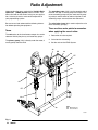
1
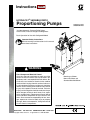
Instructions
Parts
HYDRA-CATR VARIABLE RATIO
Proportioning Pumps
309024C
*Includes Automatic Pressure Relief Valves,
Check Valves, Pressure Gauges and Regulators
Basic Operation for Use with Configured Models
Important Safety Instructions
Read all warnings and instructions in this manual.
Save these instructions.
WARNING
Plural Component Materials Hazard
Graco Inc. does not manufacture or supply any of the
reactive chemical materials that may be used in this
equipment and is not responsible for their effects. Because of the vast number of chemicals that could be
used and their varying chemical reaction, before using this equipment the buyer and the user should determine all facts relating to the materials used, including any of the potential hazards involved. Particular
inquiry and investigation should be made into the potential dangers relating to toxic fumes, fires, explosions, reaction times, and exposure of human beings
to the individual components or their resultant mixtures. Graco assumes no responsibility for loss, damage, expense or claims for bodily injury or property
damage, direct or consequential, arising from the use
of such chemical components.
GRACO INC. P.O. BOX 1441 MINNEAPOLIS, MN 55440–1441
Copyright 1999, Graco Inc. is registered to I.S. EN ISO 9001
Mounting as Shown:
Monark Air Motor and
Standard Manifold Shown
Table of Contents
Warnings . . . . . . . . . . . . . . . . . . . . . . . . . . . . . . . . . . . . . . 3
System Information . . . . . . . . . . . . . . . . . . . . . . . . . . . . . 5
Ratio Adjustment . . . . . . . . . . . . . . . . . . . . . . . . . . . . . . 10
Determining the Ratio . . . . . . . . . . . . . . . . . . . . . . . . . . 11
Set the Ratio . . . . . . . . . . . . . . . . . . . . . . . . . . . . . . . . . 12
Calculate the Ratio Setting . . . . . . . . . . . . . . . . . . . . . 13
Setting the Secondary Pump(s) . . . . . . . . . . . . . . . . . 14
Operation . . . . . . . . . . . . . . . . . . . . . . . . . . . . . . . . . . . . 15
Troubleshooting . . . . . . . . . . . . . . . . . . . . . . . . . . . . . . . 18
Service . . . . . . . . . . . . . . . . . . . . . . . . . . . . . . . . . . . . . . 20
Required Service Tools . . . . . . . . . . . . . . . . . . . . . 20
Bearing and Pump Lubrication . . . . . . . . . . . . . . . 20
Air Lubrication . . . . . . . . . . . . . . . . . . . . . . . . . . . . . 20
Detecting Bearing and Pin Wear . . . . . . . . . . . . . 20
Removing the Lever Arm from
the VRHC Frame . . . . . . . . . . . . . . . . . . . . . . . . 21
Determining Which Pin
and/or Bearing is Worn . . . . . . . . . . . . . . . . . . . 22
Fitting the Pins into the Bearings . . . . . . . . . . . . .
Storage of Spare Pins and Bearings . . . . . . . . . .
Removing the Secondary Pump
and/or the Bearings and Pins . . . . . . . . . . . . . .
Replacing the Secondary Pump
and/or the Bearings and Pins . . . . . . . . . . . . . .
Removing the Primary Pump and/or the Lower
Bearing and Pin . . . . . . . . . . . . . . . . . . . . . . . . .
Replacing the Primary Pump
and/or Bearing and Pins . . . . . . . . . . . . . . . . . .
Replacing the Lever Arm on the Frame . . . . . . .
Parts . . . . . . . . . . . . . . . . . . . . . . . . . . . . . . . . . . . . . . . .
Dimensions . . . . . . . . . . . . . . . . . . . . . . . . . . . . . . . . . . .
Technical Data . . . . . . . . . . . . . . . . . . . . . . . . . . . . . . . .
Graco Warranty . . . . . . . . . . . . . . . . . . . . . . . . . . . . . . .
Graco Information . . . . . . . . . . . . . . . . . . . . . . . . . . . . .
Related Manuals
Manual
President Air Motors
Monark Air Motors
Bulldog Air Motors
Viscount I
Displacement Pump
Displacement Pumps
Displacement Pumps
Displacement Pumps
Configurator Product Order Form
Displacement Pumps
Displacement Pumps
2
309024
No.
306982
307043
307049
307654
307430
307431
307944
684004
309025
306936
307862
22
22
22
24
25
27
28
30
38
39
40
40
Warnings
Warning Symbol
Caution Symbol
WARNING
CAUTION
This symbol alerts you to the possibility of serious
injury or death if you do not follow the instructions.
This symbol alerts you to the possibility of damage to
or destruction of equipment if you do not follow the
instructions.
WARNING
EQUIPMENT MISUSE HAZARD
INSTRUCTIONS
Equipment misuse can cause the equipment to rupture, malfunction, or start unexpectedly and result
in serious injury.
This equipment is for professional use only.
Read all instruction manuals, warnings, tags, and labels before operating the equipment.
Use the equipment only for its intended purpose. If you are uncertain about usage, call your Graco
distributor.
Do not alter or modify this equipment. Use only genuine Graco parts and accessories.
Check the equipment daily. Repair or replace worn or damaged parts immediately.
See Configurator Product Order Form 309025 for important pressure rating information. The
maximum working pressure of each model is also shown on the pump identification plate. Be sure
that all dispensing equipment and accessories are rated to withstand the maximum working pressure of your pump. Do not exceed the maximum working pressure of the lowest rated system
component.
Never operate the pump without the automatic pressure relief valves and drainage kits installed.
These valves relieve fluid pressure through a drain port at the bottom of the valve if the displacement pump pressure exceeds the working pressure.
Never exceed the recommended working pressure or the maximum air inlet pressure stated on
your pump or in the Configurator Product Order Form 309025.
Do not lift pressurized equipment.
Use only Graco approved hoses. Do not remove hose spring guards, which help protect the hose
from rupture caused by kinks or bends near the couplings.
Route the hoses away from the traffic areas, sharp edges, moving parts, and hot surfaces. Do not
expose Graco hoses to temperatures above 180F (82C) or below –40F (–40C).
Do not use the hoses to pull the equipment.
Use fluids and solvents that are compatible with the equipment wetted parts. See the Technical
Data section of all the equipment manuals. Read the fluid and solvent manufacturer’s warnings.
Comply with all applicable local, state and national fire, electrical and other safety regulations.
309024
3
WARNING
SKIN INJECTION HAZARD
Spray from the spray gun, hose leaks, or ruptured components can inject fluid into your body and
cause extremely serious injury, including the need for amputation. Splashing fluid in the eyes or on the
skin can also cause serious injury.
Fluid injected into the skin might look like just a cut, but it is a serious injury. Get immediate medical surgical treatment.
Do not point the gun/valve at anyone or at any part of the body.
Do not put your hand or fingers over the spray tip/nozzle.
Do not stop or deflect fluid leaks with your hand, body, glove, or rag.
Do not “blow back” fluid; this is not an air spray system.
Check the gun diffuser operation weekly. Refer to the gun manual.
Always have the trigger guard on the gun when dispensing.
Be sure the gun/valve trigger safety operates before dispensing.
Lock the gun/valve trigger safety when you stop dispensing.
Follow the Pressure Relief Procedure on page 15 whenever you: are instructed to relieve pressure; stop spraying/dispensing; clean, check, or service the equipment; and install or clean the
spray tip/nozzle.
Tighten all fluid connections before operating the equipment.
Check the hoses, tubes, and couplings daily. Replace worn, damaged, or loose parts immediately.
Do not repair high pressure couplings; you must replace the entire hose.
Fluid hoses must have spring guards on both ends, to help protect them from rupture caused by
kinks or bends near the couplings.
FIRE, EXPLOSION AND ELECTRIC SHOCK HAZARD
Improper grounding, poor air ventilation, open flames, or sparks can cause a hazardous condition and
result in fire, explosion, or electrostatic shock and other serious injury.
Ground the equipment, the object being dispensed, and all other electrically conductive objects in
the dispense area. Proper grounding dissipates static electricity generated in the equipment. Refer
to System Grounding on page 9.
Provide fresh air ventilation to avoid the buildup of flammable fumes from solvent or material.
Do not use the heater with flammable liquids, such as those having flash points below 200 F
(93 C).
Extinguish all open flames or pilot lights in the dispense area.
Do not turn on or off any light switch in the dispense area.
Do not use this equipment with flammable liquids.
Keep the dispense area free of debris, including solvent, rags, and gasoline.
Do not smoke in the dispense area.
Do not operate a gasoline engine within the spray area.
If there is any static sparking or you feel an electric shock while using the equipment, stop dispensing immediately. Do not use the equipment until you have identified and corrected the
problem.
4
309024
WARNING
MOVING PARTS HAZARD
Moving parts can pinch fingers.
Keep clear of all moving parts when starting or operating the equipment.
TOXIC FLUID HAZARD
Hazardous fluid or toxic fumes can cause serious injury or death if splashed in the eyes or on the
skin, inhaled, or swallowed.
Know the specific hazards of the fluid you are using.
Store hazardous fluid in an approved container. Dispose of hazardous fluid according to all
local, state and national guidelines.
Always wear protective eyewear, gloves, clothing and respirator as recommended by the fluid
and solvent manufacturer.
Avoid exposure to heated material fumes.
Provide adequate ventilation.
Graco does not manufacture or supply any of the reactive chemical components that may be
used in this equipment and is not responsible for their effects. Graco assumes no responsibility
for loss, damage, expense or claims for personal injury or property damage, direct or consequential, arising from the use of such chemical components.
System Information
This manual describes pumps designed to be part of a
Variable Ratio Hydra-Cat Pump (VRHC) dispensing
system. The VRHC proportions, mixes, and dispenses
two component fluid materials by powering two positive
displacement pump lowers from a common air motor.
This assures that the stroke rate and stroke length of
all pump lowers are proportional as set, providing
constant proportioning. The mix ratio is determined by
the movement of the outboard (slave) pump along the
arm of the machine. This movement changes the
stroke of the slave cylinder and, along with its volumetric output relationship to the master cylinder, determines the output (volumetric) ratio. The volumetric
ratio is expressed as the proportion of the volume of
fluid of the primary pump compared to the volume of
the secondary pump.
The basic proportioner includes an air motor, lower
displacement pumps, air controls, fluid inlet hardware,
fluid outlet hoses, manifold blocks and relief valve.
Additional proportioner accessories are selectable to
complete the proportioner pump (see Configurator
Product Order Form 309025).
309024
5
Typical Installation
NOTE: When pressure feeding the proportioning
pump, mount fluid pressure gauges (J) at the proportioning pump inlets to monitor proper adjustment of the
feed pump pressures. Never exceed 400 psi on the
inbound fluid pressure and never exceed 25% of
the Hydra-Cat pump outbound fluid pressure on
the feed supply.
About Typical Installations
The typical installations shown below and on page 7
are only guidelines to setting up a complete VRHC
system. For clarity, various components are shown in
the correct order but may not be shown in the exact
position of the installed system. For assistance in
designing your system, contact your nearest Graco
representative.
Airless Spray Dispensing System for
Light Viscosity Fluids
KEY
E
Air Supply
F
Base Supply
G Catalyst Supply
H
Base Supply Pump
J
Air Shutoff Valve
K
Catalyst Supply Pump
L
Air Line Filter
H
G
P
R
T
U
V
X
8
K
E
Static Mixer
Primary Pump Inlet
Secondary Pump Inlet
Solvent Pump
Airless Spray Gun
Grounded Fluid Hose
Air Pressure Gauge
13
45
46
104
120
123
124
L
123
Air Regulator
Bleed–type Master Air Valve
Pressure Relief Valve
Pressure Gauge
Mixer Manifold
Air Motor
Secondary Proportioning Pump (Slave)
J
124
X
F
U
V
45
X
R
P
X
T
46
8
104
13
120
7117B
Fig. 1
6
309024
KEY
A
B
C
D
E
F
G
H
J
K
P
R
S
U
V
W
Y
Hydraulic Pump
Mounting Stand
Hydraulic Supply Line
Hydraulic Return Line
Drain Line (from pressure reducing valve)
Pressure Gauge
Flow Control Valve
Pressure Reducing Valve
Accumulator
Feed Pumps
Hydraulic Supply Line Shutoff Valve
Hydraulic Return Line Shutoff Valve
Hydraulic Return Line Filter
Hydraulic Power Supply
Fluid Hose
Fluid Supply Line
Pump Ground Wire (required)
R
Y
P
A
F H
D
K
K
J
U
B
G
E
C
V
S
W
9433A
Fig. 2
309024
7
Installation
NOTE: Reference numbers and letters in the text refer
to Figures 1 to 18.
Location
Sit the proportioner on a flat floor positioner.
Connect the Solvent Flush Supply Line
Remove the safety panels (38,39,40). See Fig. 4 on
page 10. Connect a grounded fluid hose (X) from the
solvent flush pump to the 3/8 npt solvent flush inlet (N)
of the mixer manifold.
Connect the Fluid Supply Lines
Connect grounded fluid hoses to the 3/4 npt(f) inlet
filter fittings (R,T). If the unit will be pressure fed from
separate supply pumps, install a fluid pressure gauge
at each inlet.
NOTE: Pressurized fluid supplies must not exceed 1/4
the operating fluid pressure of the pump or 400 psi,
whichever is less. Pressure above that level will feed
through the pump and improper proportioning will
result.
System Accessories
Refer to Figures 1 and 2 and Accessories in Configurator Product Order Form 309025.
NOTE: To ensure maximum pump performance, be
sure all accessories are properly sized to meet your
system requirements.
In the air line, install an air filter (L) to remove harmful
dirt and moisture from the compressed air supply.
Downstream from the air filter, the air regulator (13)
and the bleed-type master air valve (45), install an air
line lubricator to provide automatic lubrication to the
motor.
WARNING
The bleed-type master air valve (45) is required in
your system to relieve air trapped between this
valve and the pump after the pump is shut off.
Trapped air can cause the pump to cycle unexpectedly, resulting in serious injury, including amputation.
Connect the Static Mixer to the Manifold
Connect the Air Supply Line
Connect the static mixer (P) to a grounded fluid hose
and spray gun or dispensing valve to the end of the
static mixer. If multiple guns are used, connect a
manifold or pipe “T” to the bottom of the static mix tube
and connect ball valves at each outlet. Connect an
applicator fluid hose to each ball valve.
Connect a grounded air supply hose to the 1/2 npt(f)
port of the air manifold (37). Open the bleed-type
master air valve (45), and using the pressure
gauge (8), set the air regulator (13) to the desired
pressure. See Figure 1 and 2.
Pressure Relief Valve
IMPORTANT: Each side must be flushed at each
application to ensure the lines do not plug with cured
material.
Tighten all fittings. Replace the safety
panels (38,39,40).
8
309024
Before operating the VRHC, make sure all components have rated working pressures of 3000 psi
(21 MPa, 207 bar) or greater. For more information
about the pressure relief valve, see Instruction Manual
308547.
Installation
2. Air and fluid hoses: use only electrically conductive
hoses.
Grounding
WARNING
FIRE AND EXPLOSION HAZARD
Before operating the pump, ground the
system as explained below. Also read
the section FIRE AND EXPLOSION
HAZARD on page 4.
1. Pump: use the ground wire and clamp (supplied).
See Fig. 3. Loosen the grounding lug locknut (W)
and washer (X). Insert one end of the ground
wire (Y) into the slot in lug (Z) and tighten the
locknut securely. Connect the other end of the wire
to a true earth ground.
4. Spray gun/dispense valve: ground through connection to a properly grounded fluid hose and pump.
5. Fluid supply container: follow your local code.
6. Object being sprayed: follow your local code.
7. Solvent pails used when flushing: follow your local
code. Use only metal pails, which are conductive,
placed on a grounded surface. Do not place the
pail on a nonconductive surface, such as paper or
cardboard, which interrupts the grounding continuity.
W
X
Y
Z
0864
Fig. 3
3. Air compressor: follow manufacturer’s recommendations.
8. To maintain grounding continuity when flushing or
relieving pressure, hold a metal part of the spray
gun/dispense valve firmly to the side of a grounded
metal pail, then trigger the gun/valve.
309024
9
Ratio Adjustment
Understanding the terms used with the Variable Ratio
Hydra-Cat (VRHC) System, how it functions, and
how to find and set the correct ratio(s) for your application, is the key to easier, more versatile operation of
your proportioning system.
The secondary pump (124) is on the opposite end of
the lever arm (49). It usually pumps the catalyst. One
or two secondary pumps may be used: one for pumping catalyst and the other for reducer injection. If two
secondary pumps are used, then two ratios exist.
Be sure to read and understand the following information before operating the equipment.
The ratio index clamp (30) is used to adjust the ratio
of the secondary pump(s).
Terms
There are three main points to remember
when applying the use of ratios:
The ratio refers to the simultaneous output of a certain
volume of fluid by the primary and secondary pumps.
1. Determine the ratio required.
2. Calculate the ratio setting.
The primary pump (123) is directly under the motor; it
usually pumps the base fluid.
3. Set the ratio on the VRHC System.
46
DD
49
30
EE
39
119
124
40
EE
123
38
KEY
DD Manifold Lever
EE Solvent Valves
02366B
Fig. 4
10
309024
Determining the Ratio
Determine your system conditions
If these are your conditions – one primary pump, one
secondary pump, fluids are ready-to-spray viscosity –
set the ratio as explained under Setting the
Secondary Pump(s) on page 14.
If these are your conditions – one primary pump and
one secondary pump, fluids are NOT ready-to-spray
viscosity – the ratio must be determined after the
reducer is added to the base, as instructed in
Procedure 1.
NOTE: The addition of the reducer in the base causes
changes to the ratio. To prevent reducer evaporation,
store the base in closed containers.
NOTE: Some reducers have very little ability to lubricate and may cause seals to dry out. To prolong seal
life, be sure your pump seals are compatible with the
base’s reducer. Contact your Graco distributor for the
correct seals to use.
Procedure 1: Base Is Pre-reduced
When adding reducer to the base before proportioning
with the VRHC System, determine the ratio of the
base/reducer mixture to the catalyst in order to set the
secondary pump at the correct position.
In this example, the instructions on the can say, “Mix 5
parts base to 1 part catalyst. Then reduce 3 parts of
this mixture to 1 part reducer.”
1. Add the parts of the base and catalyst to find the
parts mixture.
+
5 parts base
1 parts catalyst
6 parts mixture
2. The next statement on the can says, “Reduce 3
parts of the mixture.” So divide the parts of the
mixture by 3 to find the parts reducer.
÷
6 parts mixture
3 part catalyst
2 parts reducer
3. To determine the ratio of the secondary pump, add
the appropriate parts of base and reducer to find
the parts combined base/reducer.
+
5 parts base
2 parts reducer
7 parts combined base/reducer to
1 part catalyst:
Result: The ratio of the secondary pump is 7:1.
309024
11
Set the Ratio
Fig. 5 shows the relationship between the primary
pump and the secondary pump.
118
4
20%
4
91%
100%
4
To set the secondary pump on a standard VRHC
System with only two pumps, refer to Setting the
Secondary Pump(s) on page 14.
HH
To set the secondary pump on a non-standard VRHC
System or for an additional secondary pump, refer to
Calculate the Ratio Setting, on page 13.
NOTE: The (91) index setting provides equal primary
and secondary pump stroke lengths. 100 is 1.1 times
the primary pump stroke, allowing adjustability on both
sides of the nominal ratio setting of 91. If the same
primary and secondary pump models are used, a 91
setting will give a 1:1 ratio. If different pump models
are used, you must know the pump’s effective area to
determine the setting. The displacement pumps effective areas are listed in Configurator Product Order
Form 309025
1
2
124
123
3
3
02368
KEY
HH Lever Arm Index
1
Primary Stroke –
4” (102 mm)
2
Secondary Stroke
3
Effective Area
4
Index Setting
Fig. 5
Relationship Between Primary and
Secondary Pump
Moving the secondary pump closer to the primary
pump (to a lower index setting) reduces the secondary
stroke length, reducing its fluid output. Moving the
secondary pump further from the priming pump (to a
higher index setting) increases the secondary stroke
length, which increases its fluid output.
12
309024
Calculate the Ratio Setting
In this example,
A 5:1 ratio of base to catalyst is required.
The base/primary pump Model (e.g. 221074);
effective area is 0.470 in.
The catalyst/secondary pump Model (e.g. 221026);
effective area is 0.278 in.
2. To make sure the index setting does not exceed
the secondary pump’s maximum stroke length:
a. Multiply the index setting by 0.044 (a constant
number).
30.8
x 0.044
1.355
catalyst pump setting
constant
catalyst pump stroke length
1. To determine the base to catalyst setting.
a. Multiply the primary pump’s effective area by
91 (nominal ratio setting).
x
0.47
91
42.77
primary pump’s effective area
nominal ratio setting
answer a
b. Multiply the catalyst pump’s effective area by
the ratio required.
x
0.278
5
1.39
catalyst pump’s effective area
ratio required
answer b
a. Divide answer a by answer b to determine the
index setting.
./.
42.77
1.39
30.8
answer a
answer b
catalyst pump index setting
a. See the Pump Specifications Chart on page
12 for the pumps’ maximum stroke length. Do
not use an index setting which will exceed the
maximum stroke length for your pump model.
3. To make sure the index setting does not go below
the secondary pump minimum ratio setting, refer
to 309025 Configured Product Order Form. Do not
use a ratio higher than that specified in the maximum set position, mix ratio column for your system.
4. The number (1.355 from step 2.a.) does not
exceed the pump maximum stroke nor does it go
below the minimum ratio setting, so set the catalyst pump at the 30.8 index setting.
NOTE: The ratio index is only a reference point and
ratio checks must be performed to qualify the exact
ratio set desired..
309024
13
Setting the Secondary Pump(s)
The numbers of the pump settings, calculated from the
procedures in the section, Calculate the Ratio
Setting, correspond to the scale numbers on the lever
arm (49) of the VRHC. See Fig. 6.
30
26
16
49
WARNING
To reduce the risk of serious injury whenever you
are instructed to relieve pressure, always follow the
Pressure Relief Procedure on page 15.
1. Relieve the pressure.
2. Flush the unit as instructed on page 16 before
setting the pump.
3. Remove the safety panel (39). See Fig. 8 on
page 17.
16
4. Loosen the four capscrews (16) holding the
secondary pump(s) in place.
5. Open the fluid outlet and lift or push the lever
arm (49) to the horizontal position.
6. Move the secondary pump so that the line on the
index clamp (30) is at the desired setting on the
scale (26).
7. With the secondary pump as vertical as possible,
tighten the four screws (16) to 50 ft-lb (78 N.m).
8. Replace the safety panel (39).
14
309024
Fig. 6
02369
Operation
Pressure Relief Procedure
WARNING
2. Close the bleed-type master air valve (required in
your system).
3. Unlock the gun/valve trigger safety.
SKIN INJECTION HAZARD
The system pressure must be manually
relieved to prevent the system from
starting or spraying/dispensing accidentally. Fluid under high pressure can be injected
through the skin and cause serious injury. To
reduce the risk of an injury from injection, splashing
fluid, or moving parts, follow the Pressure Relief
Procedure whenever you:
4. Hold a metal part of the gun/valve firmly to the side
of a grounded metal pail, and trigger the gun/valve
to relieve pressure.
are instructed to relieve the pressure,
7. Leave the drain valve open until you are ready to
spray/dispense again.
stop spraying/dispensing,
check or service any of the system equipment,
or install or clean the spray tip/nozzle.
1. Lock the gun/valve trigger safety.
5. Lock the gun/valve trigger safety.
6. Open the drain valve (required in your system),
having a container ready to catch the drainage.
If you suspect that the spray tip/nozzle or hose is
completely clogged, or that pressure has not been fully
relieved after following the steps above, very slowly
loosen the tip guard retaining nut or hose end coupling
and relieve pressure gradually, then loosen completely.
Now clear the tip/nozzle or hose.
309024
15
Operation
The pumps, mixer manifold and other components
were tested with lightweight oil at the factory. Before
operating the pump, thoroughly flush the VRHC to
prevent contamination of the fluids.
Starting the Pump
NOTE: To open the mixer manifold (120), put the
handle in the down position. To close the mixer
manifold, put the handle in the up position. See Fig. 7.
System Flushing
NOTE: Flush the mixer, hose and gun/valve often
enough to prevent fluid from reacting or curing in them.
Contact your fluid manufacturer for the effective pot life
of the fluid you are using.
1. Put the pump intake hoses of the feed pumps into
5 gallon (20 liter) containers of compatible solvent.
Refer to the fluid manufacturer’s recommendations.
CAUTION
Never exceed 25% of the normal proportioner output
pressure with the feed system.
1. Start feed pump supplies and ensure fluid pressure is at least 25 psi at each pump outlet.
2. Close the bleed-type master air valve. Turn the air
regulator knob all the way out (counterclockwise).
2. Start the pump as explained below.
3. Turn on the main air supply.
3. Do not install the spray tip/nozzle yet. Hold a metal
part of the gun/valve firmly to the side of a
grounded metal pail. Using the lowest possible
fluid pressure, trigger the gun/valve into the pail.
4. Open the mixer manifold handle, trigger the gun/
valve, slowly open the bleed-type master air valve,
and turn the air regulator knob clockwise until the
pump starts.
4. When clean solvent comes from the gun/valve,
release the trigger and carefully check all connections in the system for leaks.
5. Allow the pump to cycle slowly until all the air is
pushed out of the lines. Release the trigger – the
pump will stall against the pressure.
5. Take the hoses out of the solvent and trigger the
gun/valve until all solvent has been pumped out of
the hoses.
6. The manifold handle controls fluid flow. When the
manifold is open, base and catalyst are supplied to
the gun/valve. To stop the flow, close the handle.
Solvent
Solvent
Base
Catalyst
Handle Up,
Mixer
Closed
Solvent
valve
shown
open
Base
Catalyst
Solvent
valve
shown
closed
Handle
Down,
Mixer
Open
Solvent Out
Fig. 7
16
309024
02370
Operation
46
NOTE: To open the mixer manifold (120), put the
handle in the down position. To close the mixer
manifold, put the handle in the up position. See Fig. 7
on page 16.
49
30
EE
Standard Operating Flushing
120
1. Use the solvent valves to flush contaminants and
mixed fluids from the mixer manifold, hose and
gun/valve. Follow the procedure below.
a. Start the solvent pump. Close the mixer
manifold.
39
40
119
b. Open one of the solvent valves (EE).
c.
Trigger the gun/valve into the metal pail until
the solvent valve is thoroughly flushed.
Release the trigger.
d. Close the open solvent valve. Open the other
solvent valve. Repeat step c
e. With both solvent valves open, flush until all
contaminants and fluids are removed. Release
the trigger.
2. To flush the sampling valves (119), place a
grounded metal pail under them. Turn the valve
handle to the open position. Flush until all contaminants and fluids are removed. Close the sampling
valves and solvent valves. The solvent valves
should be finger tight only, but must be tight
enough to prevent solvent from mixing with the
fluid during operation.
02366A
Fig. 8
5. Place a grounded metal pail under the sampling
valves.
6. Open the mixer manifold. Use the sampling valves
to adjust the pressures to your normal operating
pressure.
NOTE: The pressure must be within 20% of your
normal operating pressure to get a useable sample.
3. Trigger the gun/valve to relieve pressure.
Checking the Ratio
1. Open the mixer manifold (120).
2. Set the operating pressure. After determining the
operating pressure, release the gun/valve trigger
and lock the trigger safety.
7. Close the mixer manifold. Put the sampling
containers under the sampling valves.
8. Open the mixer manifold. Check the ratio. Make
sure the pressure is within 20% of the normal
operating pressure. Close the mixer manifold when
enough fluid has been dispensed into the sampling
containers.
3. Close the mixer manifold.
4. Open the sample valve (119) on the secondary
pump side approximately three turns. Open the
sampling valve on the primary pump side just one
turn. This prevents the pressure from building up
on the secondary pump, which would cause the
relief valve (46) to open.
NOTE: If the pressure is not within 20% of the normal
operating pressure, follow the flushing procedure on
page 16, and then take another sample. If the sample
ratio is incorrect, there is a problem with the sample
valves, secondary pump setting or the pump operation.
Check the pump setting or service the sampling valves
or pump.
309024
17
Troubleshooting
Troubleshooting Techniques
Because the pumps are mechanically linked, the action
of one pump can affect the readings of the second
pump. Therefore, the key to successful troubleshooting
is to be sure to isolate the problem.
For example, the secondary pump pressure, as read
on the gauge, is low and sluggish during pump
changeover. The most likely problem is a binding
primary pump.
WARNING
To reduce the risk of serious injury whenever you
are instructed to relieve pressure, always follow the
Pressure Relief Procedure on page 15.
To isolate the pump:
1. Relieve the pressure.
2. Disconnect the index clamp (30) from the
secondary pump and lean the pump out of the way
of the lever arm (49). Now you can verify the
operation of the primary pump alone.
3. Use the sampling valves (119) at the mixer
manifold (120).
a. Check the outlet ratio for the primary side.
b. With the sampling valves closed, check for
pump stalling on both the up and down
strokes.
c.
Check for rapid gauge response during pump
changeover.
4. When the operation of the primary side has been
verified, reconnect the lever arm (49) to the
secondary pump. Let the primary pump run freely
in a pail of fluid and repeat the checks in Step 3 on
the secondary side.
18
309024
WARNING
Use very low air pressure to the air motor when
making these checks. This system can produce
very high fluid pressure, which can cause serious
injury, including injection, splashing in the eyes or
on the skin, and injury from moving parts. Follow
the Pressure Relief Procedure on page 15.
WARNING
To reduce the risk of injuring or amputating a hand,
fingers or other body parts, never place your hands
or any part of your body or any tools inside the
safety panel at any time, for any reason, while the
unit is operating.
Refer to the manuals listed below to repair
the VRHC components.
Component
Ref. No.
Manual No.
President Motor
207352
306982
Bulldog Motor
20835
307049
Monark Motor
205997
307043
Viscount I
Hydraulic Motor
948699
Pump Lower
215932
307430
Pump Lower
215930
307431
Pump Lower
217339
307430
Pump Lower
222012
307944
Pump Lower
239388
307944
Pump Lower
222015
307944
Pump Lower
222017
307944
Pump Lower
222019
307944
Pump Lower
217529
306936
Pump Lower
901878
307862
Pump Lower
948640
684004
Pump Lower
948641
684004
Pump Lower
948195
307944
Pump Lower
948197
307944
307654
Troubleshooting
Problem
System won’t run or stops while
r nning
running
Cause
Solution
Air pressure or volume too low
Increase, check air compressor.
Closed or restricted air line or air
valve
Open or clean as required.
Fluid valves closed
Open fluid valves.
Clogged fluid hose
Replace fluid hose.
Air motor worn or damaged
Service air motor; see manual
306982.
Displacement pump stuck
Service displacement pump. See
manuals listed in the chart on
page 18.
Clogged filter in fluid line
Clean; replace element if necessary.
Manifold problems
Refer to manual 307400.
Check ratio
Check; replace pump.
Clogged fluid hose
Replace fluid hose.
System speeds up or runs
erraticall
erratically
Fluid containers are empty
Check often – keep filled.
Displacement pump parts worn or
damaged
Service displacement pump. See
manuals listed in the chart below.
Squeaking or knocking noise is
heard
Bearing(s) dry or worn
Lubricate; replace bearing(s) if
necessary.
Pump bottoming out
See below.
Secondary displacement pump
bottomed out because ratio index
clamp was set too far out
Adjust ratio index clamp.
Secondary displacement pump
bottomed out because top pivot
bearings are set too high
Adjust bearings. See Removing
the Lever Arm from the VRHC
Frame on page 21.
Fluids not mixing properly
System stops running on the end
of a stroke
309024
19
Service
Required Service Tools
Tool
Air Lubrication (Air Operated Motors Only)
Use for
3/32”–90 or
T-handle hex key
All setscrews
3/4” open end wrench
Clamp bolts and fluid
hose on pump outlet
1” open end wrench
Locknuts on capscrews
9/16” open end wrench
Tie rod nuts
1/2” open end wrench
Loosening tie rods from
motor base
1–1/8” open end wrench
Pivot bearing locknuts
Adjustable open end
wrench
Tightening connecting
rod to pumps
Needle nose pliers
Bending and pulling
cotter pins
Medium slotted
screwdriver
Removing shields
Small hammer and 6”
punch
Tapping out pins
If your air supply is very dry, install air line lubricators
between the air regulators and pumps for automatic air
motor lubrication. See Accessories in Configurator
Product Order Form 309025 for a lubricator.
1
Lubricate periodically with
Graco Gear Reducer Oil
1
1
1
Bearing and Pump Lubrication
WARNING
To reduce the risk of serious injury whenever you
are instructed to relieve pressure, always follow the
Pressure Relief Procedure on page 15.
1. Relieve the pressure.
2. Insert one end of the nylon hose (52) into the
wet-cup.
1
Fig. 9
02371A
Detecting Bearing and Pin Wear
3. Pour Throat Seal Liquid (44) into the hose until the
wet-cup is full.
4. Lubricate the VRHC periodically with Graco Gear
Reducer Oil (43). If the pump is operating continuously at 60 cycles/min., lubricate at the points
shown in Fig. 9 once every five days.
Service instructions are in the manuals for the separate components. See the chart on page 18.
20
309024
Audio Detection
When a bearing fails, it makes a knocking noise each
time the pump changes stroke. Shut off the system
immediately to avoid serious damage. Replace the
bearing(s).
Visual Detection
Check the movement of the lever arm (49) by watching
it through the opening in the safety panel (39). If it
bounces, shut off the system immediately to avoid
serious damage. Replace the bearing pin.
Service
Removing the Lever Arm from the VRHC
Frame
WARNING
To reduce the risk of serious injury whenever you
are instructed to relieve pressure, always follow the
Pressure Relief Procedure on page 15.
11. Remove the punch and lift the lever arm (49) off
the VRHC frame.
12. Loosen the two pivot bearing locknuts (2) and turn
the bearings (15) out of the housing (122). The
bearings should be only hand tight. If they are
tighter, use a wrench on the flats of the bearing
(15) to unscrew the bearing from the frame.
49
1. Flush the entire system with a solvent which is
compatible with the fluid being pumped. Disconnect the air line and relieve the pressure.
2. Remove the safety panels (38,39,40). See Fig. 10.
39
3. Loosen the two setscrews (59) holding the primary
displacement pump pin (35c) in the lever arm (49).
See Fig. 11. The setscrews must be backed out far
enough to clear the countersinks of the pin. Tap
the pump pin out of the lever arm and bearing.
40
4. Slide the primary pump out of the lever arm (49)
slot and save the two nylon spacers (27c).
5. Slowly lower the pump to the floor until it supports
itself with the lower bearing (14d). See Fig. 17 on
page 27.
1
12
38
6. Push down on the secondary displacement pump
end of the lever arm (49) at point (JJ) until it is at
the bottom of the stroke. See Fig. 11.
02366A
1
Fig. 10
7. Remove the two top capscrews (16a) from the
index clamp (30).
16a
8. Raise the lever arm (49) slowly. Lower the
secondary pump to the floor until it supports itself
with the lower bearing.
9. Loosen the two setscrews (17) located above the
ends of the frame pin (33). The setscrews must be
turned out far enough to clear the countersinks of
the pin.
10. Using a long punch and hammer, gently drive the
frame pin (33) out from one end until it can be
pulled out.
30
33
59
JJ
121
17
31
34a
35c
27c
15
2
CAUTION
Do not drop the pin; dents will make reassembly difficult.
49
02372
Fig. 11
309024
21
Service
Determining Which Pin and/or Bearing is
Worn
Removing the Secondary Pump and/or the
Bearings and Pins
1. Disassemble the VRHC. After the pins and bearings are removed, wipe them off with a clean rag.
1. Flush the entire system with a compatible solvent.
2. Visually inspect the pins for scoring, lines, grooves
and scratches on the area in contact with the
bearing. Then feel the surface of the pin for rough
areas or a difference in size. If these signs of wear
are detected, replace both the pin and bearing.
3. To check the bearings, hold the threaded part of
the bearing in one hand and use the other hand to
move the balls inside the bearing up and down. If
there is any noticeable movement, replace the
bearings. Also check the bearings for roundness. If
a bearing appears to be out of round (eggshaped), replace it.
WARNING
To reduce the risk of serious injury whenever you
are instructed to relieve pressure, always follow the
Pressure Relief Procedure on page 15.
2. Relieve the pressure.
3. Remove the safety panel (39). See Fig. 13.
Disconnect the inlet and outlet fluid hoses of the
secondary displacement pump (124).
Fitting the Pins into the Bearings
Tolerances between the surface of the pin and the
bearings are very close. Never force the pin into the
bearing. If the pin does not fit, sand it from the end to
just past the countersinks with 500 grit sandpaper. See
Fig. 12. If the pin still does not fit, return it to the
factory for replacement. If the pin needs replacement,
replace the bearing also.
39
1
Fig. 12
02373
02366A
Storage of Spare Pins and Bearings
Fig. 13
Completely coat spare pins and bearings with Graco
Gear Reducer Oil (43) or the equivalent when storing
these parts. Never use grease.
Continued on page 23.
22
309024
Service
NOTE: Refer to Fig. 14 for steps 4 to 10.
4. Push down on the lever arm (49) until the wrench
flats (KK) on the secondary pump (124) are just
above the wet-cup (LL). Remove the ratio index
clamp capscrews (16a) and the index clamp (30).
d. Raise the VRHC lower frame (50) and remove
the support (31b).
e. Gently tap the support pin (34b) out with a
hammer and punch.
f.
NOTE: Some fluid will drip from the pump when you
are removing the ratio index clamp.
Replace the pin and bearing.
16a
5. Raise the lever arm (49) off the pivot pin
support (31a).
30
49
6. Remove the connecting rod cotter pin (102), if the
pump has one. Unscrew the connecting rod
assembly (117, 14a, 34a, 31a) in one piece from
the pump.
17a
31a
34a
7. If you are removing only the pump, remove it from
the inlet manifold (32). If the secondary pump(s)
need repair, follow the instructions in its manual.
14a
117
8. If you are removing the bearings and pins, tilt the
secondary pump (124) forward until it rests on the
floor. Then follow Steps 9 and/or 10.
102
KK
LL
9. If you are removing the upper bearing (14a) and
support pin:
a. Loosen the two setscrews (17a). Back out the
setscrews far enough to clear the countersinks
of the support pin (34a).
124
b. Place the support (31a) in a vise. Unscrew the
connecting rod (117) from the bearing (14a).
The connecting rod and bearing are sealed
with thread sealant and may be difficult to
unscrew.
c.
32
16b
28
50
Remove the support (31a) from the vise.
Gently tap the support pin (34a) out with a
hammer and punch.
d. Replace the support pin and bearing.
10. If removing the lower bearing (14b) and support
pin (34b):
3
a. Remove one of the lower clamps (28) and
capscrews (16b).
14b
17b
b. Loosen the locknut (3) and screw the pump
manifold (32) off the bearing (14b) to remove
the secondary displacement pump (124).
c.
Remove the remaining clamp (28) and capscrew (16b) from the lower support (31b).
31b
34b
02374
Fig. 14
309024
23
Service
Replacing the Secondary Pump and/or the
Bearings and Pins
NOTE: Refer to Fig. 14 for Steps 1 to 3.
1. If only the secondary pump is being replaced:
a. Screw the secondary pump (124) into the inlet
manifold (32). The manifold must face the end
of the VRHC as shown in Fig. 14. If it does
not, rotate the secondary displacement pump
until it does, and tighten the locknut (3) against
the inlet manifold. Torque the locknut to 60 ft-lb
(81 N.m).
b. Replace the connecting rod assembly (117,
14a, 34a, 31a) onto the displacement rod, and
line up the cotter pin holes. Insert the cotter
pin (102).
c.
d. Screw the secondary displacement
pump (124) and manifold (32) onto the
bearing (14b) until it bottoms out. Be sure it is
not resting against the locknut (3).
e. Align and loosely install the two clamps (28)
and capscrews (16b).
3. If replacing the upper bearing (14a) and support
pin (34a):
a. Place a generous amount of Graco Gear
Reducer Oil (43) on the inside of the upper
bearing (14a) and the surface of the support
pin (34a).
b. Slide the support (31a) onto the bearing (14a).
Insert the support pin (34a) with the countersinks in place under the setscrew (17a) holes.
CAUTION
Raise the lever arm (49) and place the
support (31a) under the proper slot.
d. Push down the lever arm until the support fits
into the slot. If the support does not line up
with the slot, rotate it clockwise until it does.
Do not force the pin into place. Check for burrs on
the pin or in the VRHC frame if the pin does not slide
into place.
c.
e. Place the ratio index clamp (30) over the top of
the support (31a). Insert the capscrews (16a).
f.
Set the index clamp (30) for the proper ratio
and tighten the capscrews (16a).
2. If replacing the lower bearing (14b) and support
pin (34b):
a. Place a generous amount of Graco Gear
Reducer Oil (43) on the inside of the lower
bearing (14b) and the surface of the support
pin (34b).
b. Screw the locknut (3) onto the bearing (14b)
threads until the locknut bottoms out.
c.
24
Slide the bearing into the slot in the
support (31b). Insert the pin (34b) into place
with the countersinks under the setscrew (17)
holes. Tighten the setscrews to 35 in-lb (4
N.m). These are 10–32 self-locking setscrews.
If no drag is felt while turning, replace the
setscrew.
309024
Tighten the setscrews (17a) to 35 in-lb
(4 N.m). These are 10–32 self-locking screws.
If no drag is felt while turning, replace the
setscrews.
d. Place the support (31a) in a vise and screw
the connecting rod (117) onto the bearing
(14a). The connecting rod and the bearing can
be disassembled and then reused one time
before needing replacement. Be sure to seal
the connecting rod and the bearing with thread
sealant such as Loctite No. 27105 or the
equivalent. Apply 3 drops of the sealant to the
threads of the bearing.
e. Screw the connecting rod (117) onto the
pump (124) until the cotter pin holes line up (if
the displacement pump has them). Install the
cotter pin (102) and tighten the connecting rod
against the piston shoulder of the displacement rod.
f.
Follow steps 1.c to 1.f at left.
g. Tighten the capscrews (16b) at the bottom of
the secondary displacement pump (124).
Service
Removing the Primary Pump and/or the
Lower Bearing and Pin
1. Flush the entire system with a compatible solvent.
118
WARNING
121
To reduce the risk of serious injury whenever you
are instructed to relieve pressure, always follow the
Pressure Relief Procedure on page 15.
102c
2. Relieve the pressure.
3. Remove the safety panels (39,40). Disconnect the
inlet and outlet hoses on the primary displacement
pump (123).
NOTE: Refer to Fig. 15 for Steps 4 to 6.
116
103
4. Remove the three tie rod locknuts (103) and push
up on the air motor (118) until the tie rods (116)
clear the mounting holes of the displacement
pump. See Fig. 15.
5. Using a wrench on the flats of the tie rods,
unscrew them from the air motor base.
6. Remove the upper cotter pin (102c) and unscrew
the air motor from the connecting rod (121).
02375A
Fig. 15
Continued on page 26.
309024
25
Service
NOTE: If only the motor needs repair, follow the
instructions in the appropriate manual.
NOTE: Refer to Fig. 16 for Steps 7 to 15.
11. If removing the pump only, remove it from the
manifold (32). If the primary pump needs repair,
follow the instructions in the separate pump
manual.
7. Remove the lower cotter pin (102d) from the
connecting rod (121) (if the pump has one) and
loosen the two setscrews (59). The setscrews
must be backed out far enough to clear the countersink of the bearing support pin (35c).
12. If removing the lower bearing (14d) and pin (35d),
tilt the primary pump (123) forward until it rests on
the floor. Then follow steps 13 to 15.
8. Hold the connecting rod (121) and gently tap out
the support pin (35c) with a hammer and punch.
13. Loosen the lower rod end locknut (3) and unscrew
the pump manifold (32) to remove the primary
pump (123).
9. Slowly pull the connecting rod (121) away from the
lever arm (49) and tilt the pump (123) forward until
it rests on the frame. Save the two nylon
spacers (27c).
14. Loosen the two setscrews (17b). The setscrews
must be backed out far enough to clear the countersinks of the support pin (35d).
10. Unscrew the connecting rod (121) from the
displacement pump (123). If necessary, replace
the connecting rod.
15. Remove the pin (35d) and save the two nylon
spacers (27d) and the bearing (14d).
59
118
121
102c
35c
27c
121
49
02376
116
32
102d
3
14d
27d
35d
103
17b
123
02377
02375A
Fig. 16
26
309024
Service
Replacing the Primary Pump and/or
Bearing and Pins
NOTE: Refer to Fig. 17 for Steps 1 to 9 except where
noted.
1. Screw the displacement pump (123) into the inlet
manifold (32) so the outlet is facing the back.
2. Screw the connecting rod (121) onto the primary
displacement pump until the cotter pin holes line
up. Install the cotter pin (102d) if the pump has
one; if not, bottom out the connecting rod on the
displacement pump.
7. Push down the air motor and place the tie rods into
the displacement pump tie plate. Tighten the tie
rod locknuts (103).
8. To install the support pin (35c) into the upper
bearing:
a. Remove the two capscrews (16a) from the
support (31a) on the secondary pump (124).
b. Move the lever arm (49) until you can place
the nylon spacers (27c) and support pin (35c)
in line with the bearing in the connecting rod
(121).
c.
3. Pull the connecting rod upward until the displacement pump stops.
4. Screw the air motor (118) onto the connecting rod
until the cotter pin holes line up. Install the cotter
pin (102c).
5. Rotate the air motor until the air inlet port is on the
same side as the air inlet manifold (37).
6. Screw the three tie rods (116) into the air motor
base and torque to 35–50 ft-lb (47–68 N.m).
NOTE: One of the tie rods will run through the lever
arm slot.
Lubricate the support pin with Gear Reducer
Oil (43) and tap it into the upper bearing with
the countersinks facing up.
CAUTION
Do not force the pin into place. Check for burrs on
the pin or in the VRHC frame if the pin does not slide
into place. Sand with 500 grit sandpaper between the
countersinks.
d. Torque the two setscrews (59) to 35 in-lb
(4 N.m). See Fig. 18 on page 29.
e. Move the lever arm (49) back into place and
reinstall the two capscrews (16a) onto the
support (31a) of the secondary pump.
118
3
59
121
102c
35d
1
14d
49
27c
116
27d
35c
102d
17b
2
02430
103
123
32
Fig. 17
1
Torque to 60 ft-lb (81 N.m)
2
Torque to 35 in-lb (4 N.m)
02375A
309024
27
Service
9. If replacing the lower bearing (14d) and pin (35d):
a. Thread the locknut (3) all the way onto the
bearing.
b. Screw the inlet manifold (32) onto the bearing
twelve turns and tighten the locknut up to the
inlet manifold. Torque to 60 ft-lb (81 N.m).
c.
Lubricate the support pin (35d) with Gear
Reducer Oil (43). Install the pin with the countersinks facing up, into one side of the frame
base (50). Place one nylon spacer (27d) on
the end of the support pin.
d. Install the bearing (14d) and manifold (32) and
align them with the support pin (35d).
e. Tap the pin in flush with the opposite side of
the frame. Align the second nylon spacer with
the support pin, and tap the pin all the way into
the side of the frame base (50).
f.
Tighten the two setscrews (17b) onto the
support pin (35d). Torque to 35 in-lb (4 N.m).
g. Follow the procedure for replacing the primary
pump on page 27.
Replacing the Lever Arm on the Frame
CAUTION
Tolerances between the surface of the frame and
bearing are very close. Do not force the pin into
place. Check for burrs on the pin or in the VRHC
frame if the pin does not slide into place. Sand with
500 grit sandpaper between the countersinks.
NOTE: Refer to Fig. 18 for Steps 1 to 5.
1. Screw the locknuts (2) onto the pivot bearing (15).
2. Screw the pivot bearing into the frame base (50).
Adjust the distance from the top of the support
pin (33) to the bottom of the frame (50) to 26.125”
(664 mm).
3. With the bearings at the correct height and parallel
to each other, torque the locknuts (2) to
60 ft-lb (81 N.m).
4. Place a generous amount of lubricant (43) onto the
support pin, and place the lever arm (49) over the
bearings (15).
5. Slide the support pin, with the countersinks up,
through the lever arm and bearings. Torque the
two setscrews (17) to 35 in–lb (4 N.m).
NOTE: If no drag is felt while turning the setscrews,
replace them.
28
309024
Service
35
1
30
16
17
15
59
26.125”
(664 mm)
31
2
2
35d
15
124
33
27d
32
121
50
50
123
Fig. 18
1
Torque to 35 in-lb (4 N.m)
2
Torque to 60 ft-lb (81 N.m)
02378
02371A
309024
29
Parts
For Monark Options A01, M01, and Q01
126
127
130
125
128
129
117
107
or
111
124
107
118
121
116
102
122
103
123
108
106
115
105
110
109
120
02434A
30
309024
119
Parts
For Monark Options A01, M01, and Q01
Ref.
No.
Part No.
Description
102
103
104
105
106
100103
101566
104088
100139
105770
107
108
155494
155541
PIN, cotter
LOCKNUT, 3/8–16
RIVET
PLUG, pipe, 1/8 npt
FLUID PRESSURE GAUGE,
1000 psi (70 bar), 1/4 npt(m)
UNION, 3/8 npt(m) x 3/8 npt(f)
SWIVEL UNION, 90,
1/4 npt(m) x 1/4 npsm(f)
UNION, 1/4 npt(m x f)
ELBOW, street,
1/4 npt(f) x 1/8 npt(m)
SWIVEL UNION, 1/2 npt(m) x
3/8 npsm (f)
PLATE, designation
SWIVEL UNION, 3/8 npt(f) x
3/8 npsm(f), two 1/8 npt(f) ports
TIE ROD, 15.81 inch (401.6 mm)
shoulder–to–shoulder
CONNECTING ROD,
2.535 inch (64.4 mm) long
109
110
156823
158962
111
161037
114
115
116
117
172446
177088
177109
177114
Qty.
3
3
2
2
2
1
1
Ref.
No.
Part No.
Description
119
120
108233
215626
SAMPLE VALVE, needle
MANIFOLD
121
215693
122
215925
CONNECTING ROD
2.62 inch (66.5 mm) long
205997
AIR MOTOR, Monark
See parts in manual 308043
CONNECTING ROD
12.67 inch (321.8 mm) long
UNIT FRAME
1
1
see parts on pages 32 to 35
123
215932
PRIMARY DISPL. PUMP
1
See parts in manual 307430
2
2
124
222015
SECONDARY DISPL. PUMP
1
Used in M01 Option
See parts in manual 307431
215932
1
1
2
1
1
1
SECONDARY DISPL. PUMP
1
Used in A01 Option
See parts in manual 307430
222019
SECONDARY DISPL. PUMP
1
Used in Q01 Option
3
used in M0I and Q01 Options
118
2
1
See parts in manual 307400
See parts in manual 307431
125
126
162449
237060
127
128
129
130
159239
158683
113187
190738
used in A01 Option
177113
Qty.
NIPPLE, 1/2 x 1/4
RELIEF VALVE
475 (33) to 575 (400) psi (bar)
working pressure
NIPPLE, 3/8 x 1/2
ELBOW 90, 1/2 x 1/2
CONNECTOR, female, tube
TUBE, nylon
1
1
1
1
1
1
309024
31
Parts
Unit Frame All Options
1
Torque to 35 in–lb (4 N.m)
2
Torque to 60 ft–lb (81 N.m)
12
26
25
16
42
12
25
49
33
1
36
59
17 1
31
53
34
35
27
15
14
53
2
5
32
16
5
28
32
2
2
3
50
9
3
2
60
14
1
17
31
34
02432A
32
309024
Parts
Unit Frame All Options
Ref.
No.
Part No.
Description
2
3
5
9
12
100071
100155
100509
101747
103836
14
15
16
105751
105752
100060
LOCKNUT, hex, 3/4–16
NUT, 5/8–18
PLUG, pipe, 1/4 npt
PLUG, bottom, 1/4 npt(m)
SCREW, slotted head,
10–32 x 3/4 in. (19 mm)
BEARING, rod end
BEARING, rod end
CAPSCREW, hex head,
1/2–13 x 1–3/4 inch (44 mm)
SETSCREW, 10–32
SPACER
GAUGE, designation
SPACER, 1/4, nylon
CLAMP, lower
CLAMP, top, index
SUPPORT, pivot pin
17
25
26
27
28
30
31
105762
159463
177042
177086
177089
177099
177100
Qty.
2
2
3
4
12
3
2
4
8
4
2
4
2
1
2
Ref.
No.
Part No.
Description
32
33
34
35
36
42
44
177101
177105
177106
177107
177108
177144
206994
49
50
52
53
59
60
215664
215665
061135
102790
108038
189559
MANIFOLD, inlet
2
PIN, pivot, frame
1
PIN, pivot, housing
2
PIN, pivot, pump
2
PLATE, wear
2
LABEL, WARNING
4
THROAT SEAL LIQUID
(not shown)
8 ounces
ARM, lever
1
FRAME BASE, VRHC
1
HOSE, nylon (not shown) 1.5 feet
SCREW, 10–24
4
SETSCREW, 10–32
2
CAP, end
4
Qty.
Replacement Danger and Warning labels, tags and
cards are available at no cost.
309024
33
Parts
Unit Frame All Options
47
22
45
8
7
13
37
6
60
48
24
19
29
4
38
39
61
42
Ref. 60
40
21
11
1
51
56
58
12
34
309024
55
57
02433A
Parts
Unit Frame All Options
Ref.
No.
Part No.
Description
1
4
108036
100377
6
7
8
100737
100840
100960
11
12
108037
103836
13
104267
19
155470
21
157785
22
23
24
29
37
100081
158244
158491
177096
177117
STUD, fastener
12
SCREW, slotted head,
1/4–20 x 5/8 in. (16 mm)
2
PLUG, pipe, 1/2 npt
4
ELBOW, street, 1/4 npt (m x f)
1
GAUGE, air pressure, 0–200 psi
(0–14 bar)
1
NUT, sheet spring, 10–24
12
SCREW, slotted head,
10–32 x 3/4 in. (19 mm)
12
AIR REGULATOR, 1/2 npt(f) inlet
and outlet, 1/4 npt(f) gauge ports
0–125 psi (0–8 bar) range.
See manual 307204
1
SWIVEL UNION, 90, 1/2 npt(m)
x 1/2 npsm(f) swivel
1
SWIVEL UNION, straight,
3/4 npt(m) x 1/2 npsm(f) swivel
2
BUSHING, 3/8 npt(f) x 1/2 npt(m) 1
GROMMET
1
NIPPLE, 1/2 npt
1
LABEL, WARNING
1
MANIFOLD, air
1
Qty.
Ref.
No.
Part No.
Description
38
39
40
42
45
47
177118
177119
177120
177144
107142
214652
48
H53806
51
55
56
57
58
60
062035
180673
100179
100718
180674
223778
61
164672
PANEL, safety
1
PANEL, safety
1
PANEL, safety
1
LABEL, WARNING
4
AIR VALVE, bleed–type master
1
HOSE, buna–s, 1/2 in. (13 mm)
ID, coupled 3/8 npt(mbe),
1.5 ft (0.45 m) long
1
HOSE, nylon; 3/8 (10 mm) ID;
3/8 npsm(fbe); 6 ft (1.8 m) long
1
MOLDING, rubber
1.8 feet
BRACKET
1
NUT, 10–24
2
WASHER, no. 10
2
U–BOLT, 10–24
1
HOSE, PTFE, 1/4 in. (6 mm)
ID, coupled 1/4 npsm(fbe),
5 ft (1.8 m) long
1
ADAPTER, 3/8 npt x
1/4 npsm(mbe)
1
Qty.
Replacement Danger and Warning labels, tags and
cards are available at no cost.
309024
35
Parts
All President Options
130
129
131
134
132
133
111 or 127
117
102
124
118
127
128
121
135
102
116
126
104
107
125
103
115
106
123
122
120
Displacement Pump Combinations for Other Proportion Ratios
See page 38 for adjustment ratio.
Pump Combinations
Proportion
Ratio
Volume Output
gpm (l/min.)
(l/min )
At 100 psi (0.7 MPa, 7 bar)
psi (MPa,
(MPa bar)
Primary
Secondary
222012
222015
1.2:1 to 5.6:1
1.10 to 0.70
(4.2 to 2.6)
1300 to 2200
(9 to 15, 90 to 152)
222012
222017
1.4:1 to 6.7:1
1.10 to 0.70
(4.2 to 2.6)
1400 to 2200
(9.7 to 15, 97 to 152)
222012
222019
1.9:1 to 9.0:1
1.10 to 0.70
(4.2 to 2.6)
1600 to 2300
(11 to 16, 110 to 159)
Maximum to minimum ranges.
NOTE: Output pressure decreases as volume output increases.
Based on pump speed of 40 cycles per minute using No. 10 oil test media.
36
110
309024
108
119
02380B
Parts
All President Options
Ref
No.
102
Part No.
Description
Qty Options
100103
PIN, cotter
3
A04
Ref
No.
122
Description
Qty Options
215925
HOUSING, VRHC
1
All
PRIM. DISPL. PUMP1
PRIM. DISPL. PUMP2
PRIM. DISPL. PUMP3
PRIM. DISPL. PUMP3
PRIM. DISPL. PUMP3
PRIM. DISPL. PUMP3
PRIM. DISPL. PUMP3
SEC. DISPL. PUMP1
SEC. DISPL. PUMP2
SEC. DISPL. PUMP3
SEC. DISPL. PUMP3
SEC. DISPL. PUMP3
SEC. DISPL. PUMP3
SEC. DISPL. PUMP3
MOUNTING PLATE
1
1
1
1
1
1
1
1
1
1
1
1
1
1
1
A04
A06
A09
A12
A14
D02
F06
A04
A06
A09
A12
A14
D02
F06
A09
A12
A14
D02
F06
686632
103
101566
LOCKNUT, sst, 3/8–16
3
A06
All
Others
All
104
102814
GAUGE, pressure,
5000 psi (34 MPa, 350
bar), 1/4 npt(m)
2
All
106
100139
PLUG, pipe, 1/8 npt
2
All
107
155541
UNION, swivel, 90,
1/4 npt(m) x 1/4
npsm(f)
1
All
108
156823
2
All
110
158962
2
All
111
161037
UNION, 1/4 pt(m) x 1/4
npt(f)
ELBOW, street, 1/4
npt(f) x 1/8 npt(m)
UNION, swivel, 1/2
npt(f) x 3/8 npsm(f)
UNION, swivel, 3/8
npt(f) x 3/8 npsm(f)
TIE ROD, 16” (407
mm) shoulder to
shoulder
2
A04
A06
All
125
215932
215930
222012
222015
222017
222017
222015
215932
215930
222012
222015
222017
222019
222019
215690
A09
A12
A14
D02
F06
686632
126
164417
LOCKNUT
1
TIE ROD, 15.2” (385
mm) shoulder to
shoulder
TIE ROD, 16.9” (429
mm) shoulder to
shoulder
CONNECTING ROD,
2.62”(66.5 mm) long
3
A04
A09
A12
A14
D02
F06
686632
127
155494
UNION, 3/8 npt(mxf)
1
3
A06
A04
A06
All
others
All
1
115
177088
116
177111
177112
177471
117
177113
177114
177115
118
207352
119
108233
120
215626
121
215691
215692
215693
CONNECTING ROD,
2.5” (64.4 mm) long
CONNECTING ROD,
3.39” (88.1 mm) long
MOTOR, President5
2
3
123
Part No.
124
3
128
1
A09
A12
A14
D02
F06
686632
A04
1
A06
1
1
All
SAMPLING VALVE,
needle
MANIFOLD4
2
All
1
All
CONNECTING ROD,
13.5”(342 mm)
CONNECTING ROD,
11.8” (300 mm)
1
A06
1
CONNECTING ROD,
12.7” (321 mm)
1
A09
A12
A14
D02
F06
686632
A04
158212
BUSHING, 1/2 npt(m) x 1
3/8 npt(f)
NIPPLE, 1/2 x 1/4 npt
1
129
162449
130
237063
VALVE, relief, 2900 to
3600 psi (20 to 24.8
MPa, 200 to 248 bar)
1
All
All
131
159239
NIPPLE, 3/8 x 1/2 npt
1
All
132
158683
ELBOW, 90, steel
1
All
133
113187
1
All
134
190738
CONNECTOR, female,
tube
TUBE, nylon
1
All
135
237569
WIRE, ground
1
All
1See
2See
manual 307430 for parts.
manual 307431 for parts.
3See manual 307944 for parts.
4See manual 307400 for parts.
5See manual 306982 for parts
309024
37
Dimensions
D
A
F
G
B
C
D
H
E
E
A
02366A
B
C
38
309024
Four sockets
for casters.
See
Accessories
E
F
G
H
Height
President . . . . . . . . . . . . . . . . . . . 48.5” (1232 mm)
Viscount . . . . . . . . . . . . . . . . . . . . 48.5” (1232 mm)
Monark . . . . . . . . . . . . . . . . . . . . . 45.6” (1156 mm)
Bulldog . . . . . . . . . . . . . . . . . . . . . 55.5” (1410 mm)
Length . . . . . . . . . . . . . . . . . . . . . . . . . 35” (889 mm)
Width . . . . . . . . . . . . . . . . . . . . . . . . . . 18” (457 mm)
Air Inlet . . . . . . . . . . . . . . . . . . . . . . . . . . . . . 1/2 npt(f)
has four 1/4 npt(f) plugged outlets
Fluid Inlets . . . . . . . . . . . . . Two 3/4 npsm(f) swivel,
has 1/4 npt(f) plugged cleanout port
Solvent Inlets . . . . . . . . . . . . . . . . . . . . . . 1/2 npt(m)
Fluid Outlet . . . . . . . . . . . . . . . . . . . . . . . . 1/2 npt(m)
Valve Outlets . . . . . . . . . . . . . . . . . . . Two 1/4 npt(m)
Technical Data
Motor
Weight
Stroke
Length
Effective
Area
President
19 lb
(8.6 kg)
4 in
(102 mm)
14.19 Sq in
91.55 cm
Monark
13 lb
(5.9 kg)
3 in
(6 mm)
7.0 Sq in
45 cm2
Bulldog
78 lb
(35.1 kg)
4.75 in
(121 mm)
7.07 Sq in
45.61 cm
Viscount I
18.5 lb
(83 kg)
4 in
(102 mm)
7.07 Sq in
45.61 cm
Wetted Parts – See Configurator Product
Order Form 309025
Pump Model
Maximum Fluid Working Pressure Maximum Pump Air Input Pressure
President
250 bar, 25.0 MPa (3600 psi)
12.5 bar, 1.25 MPa (180 psi)
Monark
125 bar, 12.5 MPa (1800 psi)
12.5 bar, 1.25 MPa (180 psi)
Bulldog
347 bar, 34.7 MPa (4950 psi)
6.3 bar, 0.63 MPa (90 psi)
Air Pressure of Sound Tests * Sound Pressure
(25 cycles/min)
Level
** Sound Power
Level
President
12.5 bar, 1.25 MPa
(180 psi)
98 dBa
113 dBa
Monark
12.5 bar, 1.25 MPa
(180 psi)
96 dBa
112 dBa
Bulldog
7 bar, 0.7 MPa
(100 psi)
94 dBa
109 dBa
Pump Model
*
Sound pressure was measured in accordance with Cagi Pneurop, 1969.
** Sound power was measured in accordance with ISO 3744, 1981.
309024
39
Graco Standard Warranty
Graco warrants all equipment manufactured by Graco and bearing its name to be free from defects in material and workmanship on the
date of sale by an authorized Graco distributor to the original purchaser for use. With the exception of any special, extended, or limited
warranty published by Graco, Graco will, for a period of twelve months from the date of sale, repair or replace any part of the equipment
determined by Graco to be defective. This warranty applies only when the equipment is installed, operated and maintained in accordance with Graco’s written recommendations.
This warranty does not cover, and Graco shall not be liable for general wear and tear, or any malfunction, damage or wear caused by
faulty installation, misapplication, abrasion, corrosion, inadequate or improper maintenance, negligence, accident, tampering, or substitution of non–Graco component parts. Nor shall Graco be liable for malfunction, damage or wear caused by the incompatibility of
Graco equipment with structures, accessories, equipment or materials not supplied by Graco, or the improper design, manufacture,
installation, operation or maintenance of structures, accessories, equipment or materials not supplied by Graco.
This warranty is conditioned upon the prepaid return of the equipment claimed to be defective to an authorized Graco distributor for
verification of the claimed defect. If the claimed defect is verified, Graco will repair or replace free of charge any defective parts. The
equipment will be returned to the original purchaser transportation prepaid. If inspection of the equipment does not disclose any defect
in material or workmanship, repairs will be made at a reasonable charge, which charges may include the costs of parts, labor, and
transportation.
THIS WARRANTY IS EXCLUSIVE, AND IS IN LIEU OF ANY OTHER WARRANTIES, EXPRESS OR IMPLIED, INCLUDING BUT
NOT LIMITED TO WARRANTY OF MERCHANTABILITY OR WARRANTY OF FITNESS FOR A PARTICULAR PURPOSE.
Graco’s sole obligation and buyer’s sole remedy for any breach of warranty shall be as set forth above. The buyer agrees that no other
remedy (including, but not limited to, incidental or consequential damages for lost profits, lost sales, injury to person or property, or any
other incidental or consequential loss) shall be available. Any action for breach of warranty must be brought within two (2) years of the
date of sale.
Graco makes no warranty, and disclaims all implied warranties of merchantability and fitness for a particular purpose in connection
with accessories, equipment, materials or components sold but not manufactured by Graco. These items sold, but not manufactured
by Graco (such as electric motors, switches, hose, etc.), are subject to the warranty, if any, of their manufacturer. Graco will provide
purchaser with reasonable assistance in making any claim for breach of these warranties.
In no event will Graco be liable for indirect, incidental, special or consequential damages resulting from Graco supplying equipment
hereunder, or the furnishing, performance, or use of any products or other goods sold hereto, whether due to a breach of contract,
breach of warranty, the negligence of Graco, or otherwise.
FOR GRACO CANADA CUSTOMERS
The parties acknowledge that they have required that the present document, as well as all documents, notices and legal proceedings
entered into, given or instituted pursuant hereto or relating directly or indirectly hereto, be drawn up in English. Les parties reconnaissent avoir convenu que la rédaction du présente document sera en Anglais, ainsi que tous documents, avis et procédures judiciaires
exécutés, donnés ou intentés à la suite de ou en rapport, directement ou indirectement, avec les procedures concernées.
Graco Information
TO PLACE AN ORDER, contact your Graco distributor, or call one of the following numbers
to identify the distributor closest to you:
1–800–328–0211 Toll Free
612–623–6921
612–378–3505 Fax
All written and visual data contained in this document reflects the latest product information available at the time of publication.
Graco reserves the right to make changes at any time without notice.
MM 309024
Graco Headquarters: Minneapolis
International Offices: Belgium, China, Japan, Korea
GRACO INC.
P.O. BOX 1441
MINNEAPOLIS, MN
www.graco.com
PRINTED IN USA 309024 July 1999 Rev. 02/2006
40
309024
55440–1441