1
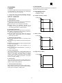
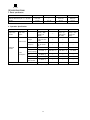
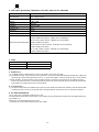
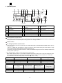
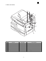
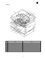
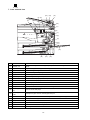
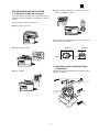
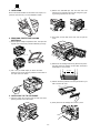
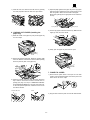
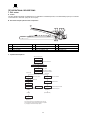
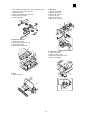
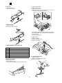
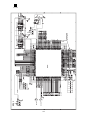
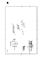
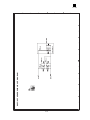
AL-1250
SERVICE MANUAL
CODE: 00ZAL1250/A1E
DIGITAL COPIER
MODEL
AL-1020
AL-1200
AL-1220
AL-1250
* This Service Manual describes only the differences from
the AL-1000/1010. For the common items with the
AL-1000/1010,please refer to the AL-1000/1010 manual.
CONTENTS
[ 1 ] GENERAL. . . . . . . . . . . . . . . . . . . . . . . . . . . . . . . . . . . . . . . . . . . . . 1 - 1
[ 2 ] SPECIFICATIONS . . . . . . . . . . . . . . . . . . . . . . . . . . . . . . . . . . . . . . 2 - 1
[ 3 ] EXTERNAL VIEWS AND INTERNAL STRUCTURE . . . . . . . . . . . . 3 - 1
[ 4 ] UNPACKING AND INSTALLATION . . . . . . . . . . . . . . . . . . . . . . . . 4 - 1
[ 5 ] OPERATIONAL DESCRIPTIONS . . . . . . . . . . . . . . . . . . . . . . . . . . 5 - 1
[ 6 ] DISASSEMBLY AND ASSEMBLY . . . . . . . . . . . . . . . . . . . . . . . . . . 5 - 2
[ 7 ] SIMULATION,TROUBLE CODES . . . . . . . . . . . . . . . . . . . . . . . . . . 7 - 1
[ 8 ] USER PROGRAMS . . . . . . . . . . . . . . . . . . . . . . . . . . . . . . . . . . . . . 8 - 1
[ 9 ] ELECTRICAL SECTION . . . . . . . . . . . . . . . . . . . . . . . . . . . . . . . . . 9 - 1
[10] CIRCUIT DIAGRAM . . . . . . . . . . . . . . . . . . . . . . . . . . . . . . . . . . . 10 - 1
●
PARTS GUIDE
Parts marked with " " is important for maintaining the safety of the set. Be sure to replace these parts with specified
ones for maintaining the safty and performance of the set.
SHARP CORPORATION
This document has been published to be used for
after sales service only.
The contents are subject to change without notice.
AL-1250
[1] GENERAL
4. Environmental
1. General
The environmental conditions for assuring the copy quality and
the machine operations are as follows:
This model is a digital personal copier produced with key words
of “Comfort able copy, Clear copy, Easy copy” providing high
copy performances and copy productivity.
A. Normal operating condition
Temperature:20˚C~25
Humidity:65 ± 5%RH
2. Target User Copy Volume: Monthly Average
B. Acceptable operating condition
Copies: 400 ∼ 800 (Max. 800)
Prints: 400 ∼ 800 (Max. 800)
Humidity (RH)
85%
3. Main features
A. High-speed laser copying
● Since warm-up time is zero, copying can be started immediately after the power switch is turned on.
● First-copy time is only 9.6 seconds (normal mode).
● Copying speed is 10 copies/min. (AL-1020) or 12
copies/min. (AL-1220/AL-1250), which adapts to business
use, allowing improvement of working efficiency.
60%
20%
B. High-quality digital image
● High-quality image copying at 600 dpi can be performed.
● In addition to the automatic exposure mode, the manual exposure can be adjusted in five steps.
● The photo mode copying function allows clear copying of
delicate halftone original images such as monochrome
photos and color photos.
10˚C
30˚C
35˚C
30˚C
40˚C
C. Optical condition
Humidity (RH)
90%
C. Substantial copying functions
● Zoom copying from 50% to 200% in 1% increments can be
performed.
● Continuous copying of maximum 99 sheets can also be performed.
● Automatic document feeding through the single pass feeder
(SPF) can be performed.
● Toner save mode reduces toner consumption by approximately 10%.
● User programs allow setting/modification of functions for
customer’s needs.
60%
15%
–25˚C
D. Scan once/Print many
This copier is equipped with a 1-page memory buffer. This
Memory allows the copier to scan an original 1 time only and
make up to 99 copies. This feature allows for improved
workflow, reduced operating noise from the copier and reduced
wear and tear on the scanning mechanism. This feature
provides for a higher reliability.
D. Supply storage condition
Humidity (RH)
90%
E. Printer feature
The AL-1250 copier can be used as a laser printer. The AL1020 and AL-1220 copiers can be used as a laser printer by installing an optional printer upgrade kit.
F. Environmentally friendly design
Paper output tray is housed in the copier for space saving.
Preheat mode and auto power shut-off mode are provided to
reduce power consumption in standby mode.
20%
–5˚C
1-1
45˚C
AL-1250
[2] SPECIFICATIONS
1. Basic specification
Item
AL-1020
AL-1220
AL-1250
AL-1200
External dimensions (W × D × H) (mm)
H379 × W518 ×
D477 mm
←
H464 × W518 ×
D477 mm
H293 × W518 ×
D445 mm
21.5 kg
21.5 kg
24.5 kg
18.0 kg
Weight
2. Operation Specification
Section item
Paper feed
section
Details
Installed memory
AL-1250
AL-1200
Voltage
100V 110V
120/127V 230V
240V
←
←
←
Frequency
Common use
for 50 and 60
Hz
←
←
←
1000 W
←
←
←
Average
(during copying)
275 Wh/H *1)
285 Wh/H *1)
285 Wh/H *1)
270 Wh/H
Average (standby)
70 Wh/H *1)
←
←
←
Pre-heat mode
40 Wh/H *1)
←
←
←
Auto power
shut-off mode
18 Wh/H *1)
←
←
←
6 MB
←
←
Not Available
Power source
Max
Power
consumption
AL-1220
←
Paper feed
system
Electrical
section
AL-1020
1 tray (250
sheet) + Multi
bypass (50
sheet)
*
1) May fluctuate due to environmental conditions and the input voltage.
2-1
2 tray (250
sheet × 2) +
Multi bypass
(50 sheet)
1 tray (250
sheet) + Multi
bypass (50
sheet)
AL-1250
3. Copy performance
Section item
Item
Tray paper feed
Copy speed
First copy time
Manual paper
feed
SPF
AB system:
A4
(Landscape)
Copy speed
(CPM)
B5
(Landscape)
Copy speed
(CPM)
Inch system 81/2" × 14"
(Landscape)
Copy speed
(CPM)
8 1/2" × 11"
(Landscape)
Copy speed
(CPM)
Void area
Same size
Enlargement
Reduction
Same size
Enlargement
Reduction
Same size
Enlargement
Reduction
Same size
Enlargement
Reduction
leading edge
Tailing edge
Side void area
leading edge
Void
Image loss
Trailing edge
Side void area
(per side)
AL-1020
9.6 sec. (Preheat mode: 16
sec. or
delow/Auto
power-shut-off
mode: 23 sec.
or delow Feed
from
Tray1/Scan
Once Print
Many Mode:
13.9 sec
Single: 10
sec./Multi: 8.0
(Pre-heat
mode: 16 sec.)
Optic at
Scanning
Position: 11.5
sec Optic at
Home Position:
13.0 sec
10
10
10
10
10
10
10
10
10
10
10
10
1 ~ 255 4 mm
4 mm or less
4 mm or less
(per side)
Same size: 3.0
mm or less
Enlarge (200):
1.5 mm or less
Reduction (50):
6.0 mm or less
Same size: 4.0
mm or less
Enlarge (200):
4.0 mm or less
Reduction (50):
4.0 mm or less
Same size: 2.0
mm or less
Enlarge (200):
2.0 mm or less
Reduction (50):
2.0 mm or less
2-2
AL-1220
AL-1250
AL-1200
←
←
←
←
←
←
←
←
—
Not Available
12
12
11
12
12
12
10
10
10
12
12
12
←
←
←
←
←
←
←
←
←
←
←
←
←
←
←
←
←
←
←
←
←
←
←
←
←
←
←
←
←
←
←
←
←
←
←
←
←
←
←
←
←
←
←
←
←
←
←
←
←
←
←
←
←
←
←
←
←
←
←
←
AL-1250
4. GDI Printer Specification (Standard for AL-1250, Option for AL-1020/1220)
Printer speed
WPPM (TBD) (A4/8-1/2 × 11, Sharp original)
First Print time
9.6 sec (A4/8-1/2 × 11, Not include communication time to the host PC and the set up
time of polygon mirror)
CPU
None
Memory
4 MB • 6 MB
Interface
IEEE1284
Emulation
Sleek type GDI
Interface Font
None
Resolution
600 dpi
Operation System Compatibility
Win 3.1, WFW 3.11, Win 95, Win 98, Win NT 4.0
Win 3.1: 486 or better processor, 8 MB Ram (16 recommended)
30 MB of additional HD Space (+5 MB for Win 32s installation)
Win 95: 486 or better processor, 8 MB Ram (16 recommended)
Minimum System Requirements
30 MB of additional HD Space.
Win 98: 486 DX or better processor, 16 MB Ram (32 recommended)
30 MB of additional HD Space.
NT 4.0: 486 or better processor, 8 MB Ram (16 recommended)
30 MB of additional HD Space.
5. Other
AL-1020
10cpm/MB/SOPM/SPF
AL-1220
12cpm/MB/SOPM/SPF
AL-1250
12cpm/MB/SOPM/SPF/GDI/2nd
*) The above models allow to use the SOPM function from the SPF.
A. SOPM function
(1) The SOPM function is effective either in the OC copy mode or in the SPF copy mode.
(2) The SOPM in the SPF copy mode: Even when a document is set on the document table and the SPF mode lamp is lighted, the
quantity display remains unchanged (does not turn to “1”). Under that condition, press the quantity set key to set the quantity.
(3) Basic operation: The first document is read and data are stored in the memory and copies of the set quantity are made.
If there is the second document, it is read and the data are stored in the memory and copies of the set quantity are made similarly.
This procedure is repeated until the end of the documents.
B. 2nd cassette door
(1) The sensor output when the 2nd cassette door is open is the same as that when PPD3 is ON. Therefore, when the initial operation
is made (the power is turned on and the side door is opened/closed) with the 2nd door open, the JAM lamp will light up.
6. AL-1200 specifications
The AL-1200 is the 12 sheets/min model of the AL-1010.
The Specifications are the same as those of the AL-1010, except for the copy speed and the average power consumption during copying (270Wh/H (*1)).
Please refer to the Service Manual of the AL-1010.
(*1) Depends on the operating conditions and the input voltage.
2-3
AL-1250
[3] EXTERNAL VIEWS AND INTERNAL STRUCTURES
1. Appearance
(3)
(4)
(5)
(2)
(1)
(14)
(6)
(7)
(15)
(16)
(8)
(9)
(10)
(13)
(19)
(12)
(1)
(4)
(7)
(10)
(13)
(16)
(19)
(17)
(20)
(11)
(18)
Operation panel
Original guides
Original cover
Bypass tray guides
Paper tray∗1
Paper output tray
Power cord socket
(2)
(5)
(8)
(11)
(14)
(17)
(20)
Original table
Document feeder tray
Side cover
Side cover open button
Handle
Paper output tray extension
Parallel interface connector∗3
(3)
(6)
(9)
(12)
(15)
(18)
(14)
SPF exit area
Feeding roller cover
Bypass tray
Front cover
Cover for optional printer interface∗2
Power switch
∗1 The AL-1250 is equipped with two paper trays.
∗2 (AL-1020/AL-1220 only) (For the AL-1020/AL-1220, a printer upgrade kit is optional.)
∗3 AL-1250 only
2. Internal
(3)
(1)
(4)
(2)
(8)
(5)
(6)
(1) TC cartridge lock release button
(4) Drum cartridge handle
(7) Charger cleaner
(7)
(2) TD cartridge
(5) Paper feed roller
(8) Transfer charger
3-1
(3) Drum cartridge
(6) Fusing unit release lever
AL-1250
3. Operational panel
(1)
(2)
(3) (4) (5)
(6)
200%
129%
100%
78%
64%
50%
(7)
(8)
(9)
(10)
(11)
MAX.
51/2 x 81/2 81/2 x11
100%
81/2 x14 81/2 x 11
81/2 x11 51/2 x 81/2
MIN.
(12) (13)
ZOOM
(14)
(15)
(16)
(17)
(1)
Exposure mode selector key and
indicators
(2)
Light and dark keys and exposure
indicators
(3)
Alarm indicators∗1
(4)
SPF indicator
(5)
SPF misfeed indicator
(6)
Copy ratio selector key and copy
ratio indicators
(7)
Zoom indicator
(8)
Copy ratio display (%) key
(9)
Display
(10) ON LINE indicator
(11) Power save indicator
(12) Tray select key
(13) Paper feed location indicators
(14) Zoom keys
(15) Copy quantity keys
(16) Clear key
(17) Print key and ready indicator
∗1
Drum replacement required indicator
When the drum counter reaches 17,000 copies, the indicator lights up. After 1,000 additional copies are made, the indicator starts
blinking and machine will not-operate (after current job) until a new cartridge is installed.
Misfeed indicator
TD cartridge replacement required indicator
When toner density is lower than a specified level, the TONER DEVELOPER CARTRIDGE REPLACEMENT indicator lights up
to warn the user.
If toner is not added after approximately 10 sheets are copied, the indicator starts blinking and machine starts to supply
toner.(Toner Developer cartridg replacement indicator keeps lighting up)
If toner density is not back to specific level after two minutes, the READ indicator goes out and Toner Developer indicator starts
blinking, and the copier stops.
∗2 ON: Indicates that the machine is in the energy saving (pre-heat) mode.
Blink: Indicates that the machine is in the process of resetting from the energy saving mode or just after supplying the power.
OFF: Indicates that resetting from the energy saving mode is completed and that the fusing temperature is in ready state.
The combinations of the above display lamps are as follows: (● = ON, ✕ = OFF)
Lamp
Immediately after power ON
Ready
Copying
Blink
✕
✕
Ready lamp
●
●
✕
Other lamps
●
●
●
Pre-heat lamp
Energy saving mode (Preheating)
Energy saving mode
(Auto power shut off)
Resetting from energy
saving mode
Copy is started during
resetting from energy
saving mode
Pre-heat lamp
●
●
Blink
Blink
Ready lamp
●
✕
●
✕
Other lamps
●
✕
●
●
Lamp
3-2
AL-1250
4. Motors and solenoids
(3)
(2)
(8)
(4)
(1)
(5)
(7)
(6)
No.
Part name
Control signal
Function,operation
(1)
Main motor
MM
Drives the copier.
(2)
Mirror motor
MRMT
Drives the optical mirror base (scanner unit).
(3)
Toner motor
TM
Supplies toner.
(4)
Cooling fan motor
VFM
Cools the optical section.
(5)
Resist roller solenoid
RRS
Resist roller rotation control solenoid
(6)
Paper feed solenoid
CPFS1
Cassette Paper feed solenoid
(7)
Multi paper feed solenoid
MPFS
Multi manual pages feed solenoid
(8)
SPF motor
SPFM
Drives the single pass feeder
3-3
AL-1250
5. Sensors and switches
(1)
(12)
(2)
(10)
(11)
(3)
(4)
(13)
(5)
(9)
(6)
(7)
(14)
(8)
No.
MHPS
Transmission sensor
(2)
Name
Mirror home position
sensor
POD sensor
POD
Transmission sensor
(3)
PPD2 sensor
PPD2
Transmission sensor
(4)
Cassette detection switch
CED1
Microswitch
(5)
Manual feed detection
switch
MFD
Transmission sensor
(6)
PPD1 sensor
PPD1
Transmission sensor
(7)
Door switch
DSW
Micro switch
(8)
Door switch
DSW
Micro switch
(9)
Drum reset switch
DRST
Micro switch
(10)
SPF sensor
SPID/SD
Transmission sensor
SW
(11)
SPPD sensor
SPPD
Transmission sensor
(12)
SDOD sensor
SDOD
Transmission sensor
(13)
2nd cassette
DSW
Micro switch
(14)
PPD3 sensor
PPD3
Transmission sensor
(1)
Signal
Type
3-4
Function
Mirror (scanner unit)
home position detection
Paper exit detection
Paper transport detection
2
Cassette installation
detection
Manual feed paper
detection (single only)
Paper transport detection
1
Door open/close
detection (safety switch
for 5V)
Door open/close
detection (safety switch
for 24V)
New drum detection
switch
Paper entry detection
Cover open/close
detection
Paper transport detection
SPF open/close detection
Book sensor
2nd cassette door open
detection
Paper transport
detection 3
Output
“H” at home position
“H” at paper pass
“L” at paper pass
“H” at cassette insertion
“L” at paper detection
“L” at paper pass
1 or 0V of 5V at door
open
1 or 0V of 24V at door
open
Instantaneously “H” at
insertion of new drum
“L” at paper pass
“L” at paper pass
“L” at paper pass
1 or 0V of 5V at door
open
“L” at paper pass
AL-1250
6. PWB unit
(2)
(1)
(9)
(5)
(8)
(6)
(4)
(3)
(7)
No.
Name
Function
(1)
Exposure lamp invertor PWB
Exposure lamp (Xenon lamp) control
(2)
Main PWB (MCU)
Copier control
(3)
Operation PWB
Operation input/display
(4)
Power PWB
AC power input, DC voltage control, High voltage control
(5)
CCD sensor PWB
For image scanning
(6)
LSU motor PWB
For polygon motor drive
(7)
TCS PWB
For toner sensor control
(8)
LSU PWB
For laser control
(9)
Memory PWB 6MB
For memorying data
3-5
AL-1250
7. Cross sectional view
(19) (16)
(17)
(4) (6)
(5)
(3)
(18)
(1)
(2)
(7)
(8)
(9)
(10)
(11)
(12)
(15)
No.
(14)
Part name
(13)
Function and operation
(1)
Scanner unit
Illuminates the original with the copy lamp and passes the reflected light to the lens unit
(CCD).
(2)
Exposure lamp
Exposure lamp (Xenon lamp) Illuminates original
(3)
Lens unit
Scans the original image with the lens and the CCD.
(4)
LSU (Laser unit)
Converts the original image signal into laser beams and writes onto the drum.
(5)
Paper exit roller
Roller for paper exit
(6)
Main charger
Provides negative charges evenly to the drum surface.
(7)
Heat roller
Fuses toner on the paper. (Teflon roller)
(8)
Pressure roller
Fuses toner on the paper. (Silicon rubber roller)
(9)
Drum
Forms images.
(10)
Transfer unit
Transfers images onto the drum.
(11)
Pickup roller
Picks up the manual feed paper. (In multi feed only)
(12)
Manual paper feed
tray
Tray for manual feed paper
(13)
Manual paper feed
roller
Transport the paper from the manual paper feed port.
(14)
PS roller unit
Takes synchronization between the lead edge and the rear edge of the paper.
(15)
Paper feed roller
Picks up a sheet of paper from the cassette.
(16)
Pickup roller
Picks up documents.
(17)
Separation roller
Separates documents to feed properly.
(18)
PS roller
Feeds documents to the scanning section.
(19)
Paper exit roller
Discharges documents.
3-6
AL-1250
● subject to extreme temperature or humidity changes, e.g.,
near an air conditioner or heater.
[4] UNPACKING AND INSTALLATION
1. A WORD ON COPIER INSTALLATION
Improper installation may damage the copier. Please note the
following during initial installation and whenever the copier is
moved.
Do not install your copier in areas that are:
● damp, humid, or very dusty
Be sure to allow the required space around the machine for
servicing and proper ventilation.
● exposed to direct sunlight
8"(20cm)
4"
(10cm)
8"(20cm)
4"
(10cm)
2. CHECKING PACKED COMPONENTS AND
ACCESSORIES
Open the carton and check if the following components and accessories are included.
● poorly ventilated
Power cord
Interface cable
(IBM PC/AT or compatible computer)
(AL-1250 only)
Operation manual
(Printer driver (CD-ROM)
AL-1250 only)
TD cartridge
Copier
Drum cartridge
(installed in copier)
4-1
AL-1250
2) Remove the CAUTION tape from the front cover and
remove the two protective pins from the fusing unit by pulling the strings upward one at a time.
3. UNPACKING
Be sure to hold the handles on both sides of the copier to unpack the copier and carry it to the installation location.
Protective pins
CAUTION tape
3) Push gently on both sides of the front cover to open the
cover.
4. REMOVING PROTECTIVE PACKING
MATERIALS
1) Remove pieces of tape and protective cover. Then open the
original cover and remove protective materials (a) and (b).
AL-1020/AL-1220
4) Remove the TD cartridge from the bag. Remove the protective paper. Hold the cartridge on both sides and shake it
horizontally four or five times.
AL-1250
4 or 5 times
2) Use a coin (or suitable object) to remove the screw.
Store the screw in the paper tray because it will be used if
the copier has to be moved.
5) Hold the tab of the protective cover and pull the tab to your
side to remove the cover.
5. INSTALLING THE TD CARTRIDGE
1) Open the bypass tray and then open the side cover while
pressing the side cover open button.
6) Gently insert the TD cartridge until it locks in place.
4-2
AL-1250
7) Close the front cover and then the side cover by pressing
the round projections near the side cover open button.
4) Adjust the paper guides on the paper tray to the copy paper
width and length. Squeeze the lever of paper guide (A) and
slide the guide to match with the width of the paper.
Move paper guide (B) to the appropriate slot as marked on
the tray.
Paper guide (B)
Paper guide (A)
5) Fan the copy paper and insert it into the tray. Make sure the
edges go under the corner hooks.
6. LOADING COPY PAPER (installing the
paper tray)
1) Raise the handle of the paper tray and pull the paper tray
out until it stops.
6) Gently push the paper tray back into the copier.
2) Remove the pressure plate lock. Rotate the pressure plate
lock in the direction of the arrow to remove it while pressing
down the pressure plate of the paper tray.
7. POWER TO COPIER
1) Ensure that the power switch of the copier is in the OFF
position. Insert the attached power cord into the power cord
socket at the rear of the copier.
3) Store the pressure plate lock which has been removed in
step 2 and the screw which has been removed when unpacking (see page 4-2, step 2 of REMOVING PROTECTIVE PACKING MATERIALS) in the front of the paper tray.
To store the pressure plate lock, rotate the lock to fix it on
the relevant location.
Pressure plate lock
Screw
2) Plug the other end of the power cord into the nearest outlet.
4-3
AL-1250
[5] OPERATIONAL DESCRIPTIONS
1. SPF section
A. Outline
The SPF (Single Path Feeder) is installed to the AL-1000/1200 as a standard provision, and it automatically copies up to 30 sheets
of documents of a same size. (Only one set of copies)
B. Document transport path and basic composition
(1)
(4)
(7)
(10)
Pickup roller
Paper stopper
Paper entry sensor
Paper exit roller
(2)
(5)
(8)
(11)
Sheet of document for paper feed
Document feed roller
PS roller D
Paper exit follower roller
(3)
(6)
(9)
(12)
Set detection ACT
Separation sheet
Transport follower roller
Document tray
C. Operational descriptions
Time chart (Tray feed)
Document set
SPID ON
Document set sensor
Document feed unit lamp ON
PSW ON
MIRM rotation
(Copier side)
MM rotation
CPFS ON
Main motor rotation
Copy start
The scanner is shifted
to the exposure position.
(SPF side)
SPFM rotation
SPF motor rotation
Paper feed
SPUS ON
Document feed
SPPD ON
Document transport sensor
PPD ON
RRC ON
Synchronization
Paper transport
Document transport
(Transfer)
(Exposure)
(Fusing)
(Document exit)
POD ON
(Paper exit)
In the zooming mode, the magnification ratio in the sub
scanning direction (paper transport direction) is adjusted
by changing the document transport speed.
5-1
AL-1250
D.
a.
b.
c.
d.
Cases where a document jam is caused
When SPPD is ON (document remaining) when the power is turned on.
When SPPD is not turned ON within about 1.5 sec (at 100% copy) after starting the document feed operation.
When SPPD is not turned on within about 4.7 sec (at 100% copy) after turning on SPPD.
When the SPF document jam release door or the OC cover is opened during document transport (SPF motor rotating).
1) Remove the belt, the paper feed frame SP, and two harnesses.
2) Remove the pickup unit.
[6] DISASSEMBLY AND ASSEMBLY
1. SPF
No.
1
Part name Ref.
A
Sensor PWB
B
Pickup solenoid
C
Clutch
D
Manual paper feed roller, pickup roller
E
Belt
F
SPF motor
G
Paper entry sensor
H
PS roller
I
Paper exit roller
1
2
3
4
3
1
Pickup unit removal
1) Remove three fixing pawls from the bottom of the machine.
2) Remove the front cover and the rear cover.
1
2
*
2
1
5-2
When installing the parts, be careful of the hole position of
the paper frame SP.
AL-1250
A. Sensor PWB
1) Remove two screws from the bottom of the pickup unit.
2) Remove the upper cover.
C.
1)
2)
3)
4)
2
Clutch
Remove the E-ring.
Remove the pulley and bush.
Slide the bush in the arrow direction.
Lift the clutch, and 5) remove the clutch.
2
1
5
1
1
3
4
1) Remove two screws.
2) Remove the sensor PWB.
3) Remove the harness.
1
1
3
1) Remove the E-ring.
2) Remove the parts.
2
1
B. Pickup solenoid
1) Remove two screws.
2) Remove the pickup solenoid
2
2
D.
1)
2)
3)
4)
1
Manual paper feed roller, pickup roller
Lift the paper stopper.
Slide the takeup roller unit.
Slide the bush in the arrow direction.
Remove the takeup roller unit.
A
A
1
*
When installing, hang iron core A on the solenoid arm.
2
3
6-1
4
AL-1250
*
When installing the takeup roller, hang the projection of the
takeup roller unit on the solenoid arm.
1) Remove the parts.
2) Remove the manual paper feed roller.
3) Remove the pickup roller.
4) Remove the parts.
F.
1)
2)
3)
4)
5)
6)
4
SPF motor
Remove the harness.
Remove four screws.
Remove the drive unit.
Remove the belt.
Remove two screws.
Remove the SPF motor.
6
3
1
2
1
5
1
5
2
3
4
2
1
Transport unit removal
1) Remove two screws.
2) Remove the document tray unit.
3) Remove five screws.
4) Remove the transport unit.
2
3
1
G.
1)
2)
3)
4)
3
Paper entry sensor
Loosen the screw.
Open the paper exit PG.
Remove the paper entry sensor.
Remove the harness.
3
3
1
4
E. Belt
1) Remove the belt.
4
3
1
2
1
6-2
AL-1250
1)
2)
3)
4)
H. PS roller
1) Remove the parts.
2) Remove the PS roller.
Open the right cabinet.
Remove three screws.
Remove one connector.
While tilting down the 2nd connection arm A, pull and
remove the paper feed unit toward you.
C
D
1
D
2
1
3
4
B
I. Paper exit roller
1) Remove the parts.
2) Remove the paper exit roller.
A
1
1
2
*
*
When installing, securely insert two bosses C on the machine
side and two bosses D on the paper feed unit side. Be sure
to fix the earth B.
Insert the 2nd page feed.
A.
1)
2)
3)
1
Paper sensor
Remove the pawl.
Remove the paper sensor.
Remove the harness.
2
3
2. 2ND CASSETTE (AL-1250 only)
No.
Part name Ref.
A
Paper sensor
B
Cassette detection SW
C
Paper feed solenoid
D
Transport roller
E
Paper feed clutch
F
2nd paper feed roller
1
B.
1)
2)
3)
Paper feed unit removal
1) Remove the screw.
2) Remove the rear cover.
*
When installing, engage the pawl and install the unit.
Cassette detection SW
Remove the pawl.
Remove the cassette detection SW.
Remove the harness.
1
3
2
2
1
A
2
6-3
AL-1250
C.
1)
2)
3)
Paper feed solenoid
Remove the screw.
Remove the connector.
Remove the paper feed solenoid.
E.
1)
2)
3)
Paper feed clutch
Remove the E-ring.
Remove the paper feed clutch.
Remove the parts.
2
3
A
2
1
3
1
D. Transport roller
1) Remove two E-rings.
2) Remove the transport roller.
*
4
When installing, fit the cut surface A.
F. 2nd paper feed roller
1) Remove the E-ring and the parts.
2) Remove the 2nd paper feed roller.
1
A
1
B
A
3
B
2
*
2
Install so that the earth spring A is brought into contact over
bearing B.
C
1
D
*
6-4
When installing, hang the 2nd connection arm on the 2nd
connection arm SP B. Be sure to install so that the earth
spring C is in contact under the bearing D.
AL-1250
[7] SIMULATION TROUBLE CODE
1. Contents of simulations
Main code
Sub code
2
2
Contents
SPF sensor status display
(Operation/Procedure)
ON/OFF of the SPF sensor is displayed with the lamps on the operation panel.
Sensor name
Document set sensor (SPID)
SPF document transport sensor (SPPD)
SPF cover sensor (SCOD)
SPF open/close sensor (SDSW)
26
Display lamp
Developer cartridge replacement lamp
Jam lamp
Photoconductor cartridge replacement lamp
SPF jam lamp
3
SPF motor operation check
(Operation/Procedure)
When the start key is pressed, the SPF motor rotates for 10 sec at the speed corresponding to
the currently set magnification ratio.
4
SPF paper feed solenoid (SPUS) operation check
(Operation/Procedure)
When the start key is pressed, the SPF paper feed solenoid repeats ON (500 ms) and OFF (500
ms) 20 times.
5
RSPF pressure release solenoid (SPFS) operation check
(Operation/Procedure)
When the start key is pressed, the RSPF document transport solenoid (SPFS) repeats ON (500
ms) and OFF (500 ms) 20 times.
6
RSPF resist clutch (SRRC) operation check
(Operation/Procedure)
When the start key is pressed, the RSPF resist clutch (SRRC) repeats ON (500 ms) and OFF
(500 ms) 20 times.
7
RSPF gate solenoid (SGS) operation check
(Operation/Procedure)
When the start key is pressed, the RSPF gate solenoid (SGS) repeats ON (500 ms) and OFF
(500 ms) 20 times.
2
SPF setting
(Operation/Procedure)
1. When this simulation is executed, the currently set code number of SPF is displayed.
2. Enter the code number and press the start key. The setting is changed.
Code number
0
1
2
3
SPF
Without SPF
With SPF
With RSPF
Second cassette setting
(Operation/Procedure)
1. When this simulation is executed, the currently set code number of the second cassette is
displayed.
2. Enter the code number and press the start key. The setting is changed.
Code number
0
1
Second cassette
Without second cassette
With second cassette
7-1
AL-1250
Main code
Sub code
26
43
Contents
Side void amount setting
(Operation/Procedure)
1. When this simulation is executed, the currently set code number of the side void amount is
displayed.
2. Enter the code number and press the start key. The setting is changed.
Code number
0
1
2
3
4
5
6
7
8
9
10
44
Setting
0 mm
0.5 mm
1.0 mm
1.5 mm
2.0 mm *Default
2.5 mm
3.0 mm
3.5 mm
4.0 mm
4.5 mm
5.0 mm
SPF document rear edge detection setting (Used to erase the document rear edge shade
generated in SPF reduction copy.)
When this simulation is executed, the currently set code number is displayed. Enter the desired
code number and press the START key, and the display will be changed. The document rear
edge scanning area in SPF reduction (less than 100%) copy is changed.
The code number is changeable in the range of 0 - 8.
The default value is 4, and 2 mm of the document rear edge is cut.
When the value is changed by 1, the area is changed by 1 mm.
50
1
Lead edge image position and paper lead edge/rear edge void adjustment
(Outline)
This adjustment is used to adjust the copy image position and lead edge/rear edge void amount
on the copy paper by adjusting the image scan start position and the print start position (resist
roller ON timing) at 100%.
(Operation/Procedure)
1. When this simulation is executed, the currently set value is displayed in two digits. (Center
value: 50)
2. When the copy mode select key is pressed, each setting mode and the display are changed.
∗ The selected adjustment mode is indicated by the lamps as shown in the table below.
3. Enter the adjustment value with the 10-key and press the start key. The set value is stored
and a copy is made. (When the set value is increased by 1, the void amount is shifted by 0.1
mm.)
4. When the clear key is pressed, the set value is stored and the simulation mode is terminated.
Adjustment mode
Print start position
Image lead edge void amount
Image scan start position (Scanner)
Image rear edge void amount
SPF image scan start position
7-2
Display lamp
AE lamp
TEXT lamp
PHOTO lamp
AE, TEXT, PHOTO lamp
AE, TEXT lamp
AL-1250
Main code
Sub code
Contents
50
1
(Adjustment method)
1. Set the print start position (A: AE ON), the lead edge void amount (B: TEXT ON), the scanning
start position (C: PHOTO ON) to zero and make a copy of a scale at 100%.
2. Measure the image loss R (mm) of the scale.
(Example)
Set as C = 10 × R (mm). (Example: Set to 30.)
Distance from the paper
∗ When C is increased by 10, the image loss is
lead edge to the image
H = 5mm
decreased by 1 mm. (Default: 5)
3. Measure the distance H (mm) from the paper lead
Image loss
edge to the image print start position.
R = 3mm
Set as A = 10 × R (mm). (Example: Set to 50.)
∗ When the value of A is increased by 10, the
image lead edge is shifted toward the paper
lead edge by 1 mm. (Default: 50)
4. Set the lead edge void amount as B = 50 (2.5
mm). (Default: 50)
∗ When the value of B is increased by 10, the
void is increased by about 1 mm.
(For 25 or less, however, the void amount
becomes zero.)
✩ The SPF adjustment is made by adjusting the SPF image scan start position immediately after
turning on the power.
10
Center offset adjustment
(Outline)
The center offset position of copy image on the copy paper and that of document scan are
adjusted by adjusting the scan left margin of ASIC and the print left margin register set value.
(Operation/Procedure)
1. When this simulation is executed, the currently set value is displayed.
2. For a machine with a multi manual paper feed unit installed, when the copy mode select key is
pressed, each set mode and display are changed.
For a machine with a single manual paper feed unit installed, when the copy mode select key
is pressed, each set mode and display are changed.
✩ Machine with a multi manual paper feed unit
Adjustment mode
Print center offset (Main cassette paper feed)
Print center offset (2nd cassette paper feed)
Print center offset (Manual paper feed)
OC/Document center offset
SPF/Document center offset
AE,
AE,
AE,
AE,
AE,
Display lamp
main cassette lamp
2nd cassette lamp
Manual paper feed lamp
TEXT lamp
TEXT, PHOTO lamp
✩ Machine with a single manual paper feed unit
Adjustment mode
Display lamp
Print center offset (Main cassette paper feed) AE, Main cassette lamp
Print center offset (Manual paper feed)
AE lamp (Blinking)
OC/Document center offset
AE, TEXT lamp
SPF/Document center offset
AE, TEXT, PHOTO lamp
7-3
AL-1250
Main code
Sub code
Contents
51
2
Resist amount adjustment
(Outline)
The contact pressure of paper onto the resist roller and the RSPF resist roller is adjusted.
(Operation/Procedure)
1. When this simulation is executed, the currently set value is displayed.
2. For a machine with a multi manual paper feed unit installed, when the copy mode select key is
pressed, each set mode and display are changed.
For a machine with a single manual paper feed unit installed, when the copy mode select key
is pressed, each set mode and display are changed.
✩ Machine with a multi manual paper feed unit
Adjustment mode
Main cassette paper feed
2nd cassette paper feed
Manual paper feed
RSPF document feed
AE,
AE,
AE,
AE,
Display lamp
main cassette lamp
2nd cassette lamp
manual paper feed lamp
TEXT, PHOTO lamp
✩ Machine with a single manual paper feed unit
Adjustment mode
Main cassette paper feed
Manual paper feed
RSPF document feed
64
Display lamp
AE, main cassette lamp
AE lamp (Blinking)
AE, TEXT, PHOTO lamp
6
SPF exposure correction amount adjustment
(Outline)
The APF exposure correction amount is adjusted by adjusting the change in Vref voltage for the
OC mode.
(Operation/Procedure)
1. When this simulation is executed, the currently set value is displayed.
2. Enter the adjustment value with the 10-key and press the start key. The entered value is
stored and a copy is made.
∗ When the adjustment value is changed by 1, the D/A output is changed by +1 digit (dark)
for OC exposure. When it is changed by –1, the output is changed by –1 digit (light).
3. When the clear key is pressed, the entered value is stored and the simulation mode is
terminated.
1
Self print by the engine only (1 by 2 mode)
(Outline)
Used to print in the 1 by 2 mode by ignoring the state of the optical system.
(Operation/Procedure)
1. When this simulation is executed, warming up is made and the ready lamp is lighted.
2. Select with the cassette select key and press the start key. Paper is fed from the selected
cassette and printing is performed.
In the 1 by 2 mode, one line is printed and two lines are not printed.
7-4
AL-1250
[8] USER PROGRAM
The conditions of factory setting can be changed according to the use conditions.
1. Functions which can be set with the user program
Function
Contents
Factory setting
● When a certain time is passed after completion of copying, this function returns to the
Auto clear.
60 sec
initial state automatically. The time to reach the initial state can be set in the range of
30 sec to 120 sec by the unit of 30 sec. This function can be disabled.
● When the copier is left unused with the power ON, the power consumption is
automatically reduced to about 40Wh/H (∗ Note).
The time to start this function can be set in the range of 30 sec to 90 sec by the unit
of 30 sec. This function cannot be disabled.
Pre-heat.
90 sec
● When this function is operated, the pre-heat lamp on the operation panel lights up.
To return to the initial state, press any key on the operation panel. (When the COPY
button is pressed, a copy is made after returning to the initial state.)
● When the copier is left unused with the power ON, the power consumption is
automatically reduced to about 18Wh/H (∗ Note). The time to start this function can be
set in the range of 2 min to 120 min.
Auto shut off
5 min
passing time.
● When this function is operated, all the lamps except for the pre-heat lamp on the
operation panel turn off.
To return to the initial state, press the COPY button.
After completion of copying with the automatic document feeder (SPF), when documents
Stream feeding.
are set while the SPF indicator is blinking (for about 5 sec), the documents are
Set
automatically fed.
Auto shut off setting ● Used to set or cancel this function.
Set
∗Note: The power consumption values in pre-heat and auto shut off may be varied depending on the use conditions.
2. Change the setting.
Function name
Auto clear
Pre-heat
Auto shut off passing time
Stream feeding
Auto shut off setting
Example: Changing the time to operate the auto shut off function (Change from 60 sec to 90 sec)
1) Press the right and the left exposure adjustment keys
simultaneously to start setting.
● Keep pressing the keys for five sec.
● Display lamps (
,
,
blink simultaneously and “-” is displayed on the copy quantity display.
2) Select the function code with the 10-digit key (copy
quantity set key).
● The number of the selected function blinks on the digit of 10
on the copy quantity display.
● For auto clear, select “1.”
● For setting, refer to the following function codes.
Function
name
Auto clear
Set code
Function
name
0 (Cancel)
1 (30 sec)
∗2 (60 sec) Pre-heat
3 (90 sec)
4 (120 sec)
Set code
[Cancel] If a wrong code is entered, press the clear key and
enter the correct function code.
3) Press the COPY button.
● The number blinking on the digit of 10 of the coyp quantity
display is lighted.
● The number of the current set code blinks on the digit of 1.
4) Select the setting code with 1-digit key (copy quantity
set key).
● To set to 90 sec, select “3.”
● For setting, refer to the following set codes.
Function
name
0 (30 sec)
1 (60 sec)
∗2 (90 sec) Auto shut
off
Function code
1
2
3
4✽
5
Set code
Function
name
0 (2 min)
∗1 (5 min)
2 (15 min) Stream
3 (30 min) feeding
4 (60 min)
5 (120 min)
∗ : Factory setting
● The number of the selected set code blinks on the digit of 1
of the copy quantity display.
Set code
Function
name
0 (Cancel)
∗1 (Setting)
Set code
0 (Cancel)
∗1 (Setting)
Auto shut
off setting
[Note] To set another function, press the clear key after completion of this operation and perform the procedure
from 2.
6) Press either one of exposure adjustment keys
(
or
) to complete the setting.
[Cancel] When a wrong number of the function code is set,
press the clear key and perform the procedure again
from 2.
5) Press the COPY button.
● The number blinking on the digit of 1 of the copy quantity
display is lighted up. This means the setting is completed.
● Display lamps (
,
,
) go off and the copy quantity display returns to the normal state.
8-1
AL-1250
3. AE level adjustment (OC mode)
[Input method]
When the PHOTO lamp lights up, press and hold the density
select key for 5 sec, and the AUTO mode lamp will blink and
the adjusted level will be displayed on the exposure level display.
[Adjustment]
For adjustment, press the density adjustment key too select the
density in 5 steps.
[Terminating method]
Press the density select key, and the model display will turn
from blinking to lighting to terminate the AE level adjustment.
4. AE level adjustment (SPF mode)
[Input method]
While the SPF mode lamp is lighting, when the PHOTO mode
lamp lights up, press and hold the density select key for 5 sec,
and the AUTO mode lamp will blink and the adjusted level will
be displayed on the exposure level display.
[Adjustment]
For adjustment, press the density adjustment key to select the
density in 5 steps.
[Terminating method]
When the density select key is pressed, the mode display will
turn from blinking to lighting to terminate the AE level adjustment.
5. Toner save mode setup and cancel
[Input method]
When the TEST mode lamp lights up, press and hold the density select key for 5 sec, and the PHOTO mode lamp will turn
from blinking to lighting and the adjusted level will be displayed
on the exposure level display.
[Setup/Cancel]
Press the left key: Level “1” ON, toner save mode setup Press
the right key: Level “5” ON, toner save mode cancel.
[Terminating method]
When the density select key is pressed, the mode display turns
from blinking to lighting to terminate setup.
8-2
AL-1250
[9] ELECTRICAL SECTION
1. Block diagram
A. Overall block diagram
9-1
AL-1250
B. Main PWB block diagram
9-2
AL-1250
2. Circuit descriptions
A. Main PWB (MCU)
(1) CPU signal table
The additional signal is as follows:
Pin No.
Signal name
In/Out
During operation
109
SIN3
Input
Sensor input 3
The signals of function change are as follows:
Pin No.
Signal name
In/Out
During operation
119
MRMT3
Motor output
Mirror motor/SPF motor control signal
120
MRMT2
Motor output
Mirror motor/SPF motor control signal
121
MRMT1
Motor output
Mirror motor/SPF motor control signal
122
MRMT0
Motor output
Mirror motor/SPF motor control signal
(2) ASIC signal table
The additional signal is as follows:
Pin No.
Signal name
In/Out
Connection
Descriptions
201
SGS
Output
TR array IC
SPF gate solenoid
control signal. “H”: Gate
solenoid ON
202
SRRC
Output
TR array IC
SPF resist roller clutch
control signal. “H”:
Clutch ON
203
SPUS
Output
TR array IC
SPF pickup solenoid
control signal. “H”:
Solenoid ON
208
SPFS
Output
TR array IC
SPF paper feed solenoid
control signal. “H”:
Solenoid ON
209
SMSEL
Output
TR array IC
SPF/mirror motor relay
switch signal. “L”: Mirror
motor, “H”: SPF motor
227
CPFS2
Output
TR array IC
2nd cassette paper feed
solenoid control signal.
“H”: Solenoid ON
(3) Input signal table
The additional signals are as follows:
Signal name
SPF
2nd
Descriptions
SPID
SPF paper entry detection signal
SPPD
SPF paper transport detection signal
SDOD
SPF open/close detection signal
SDSW
SPF cover open/close detection signal
CED2
2nd cassette section cassette presence detection
PPD3
2nd cassette section paper transport detection
9-3
AL-1250
(4) Mirror motor circuit
The mirror motor is a stepping motor. Its driver is IC113 constant-current chopper control IC (SLA7024). For control, the CPU
outputs a drive signal to IC113 to drive the mirror motor by 1-2 phase excitement.
The SPF motor and the mirror motor are switched with relays RY1 and RY2. The switching signal is SMSEL-. When SMSELis LOW, a current flows through the SPF motor. When it is HIGH, a current flows through the mirror motor.
24V-mir
24V
RY102
G5V-2(OMRON)
M
SPF motor
M
RY101
/SMSEL
ULN2003
9-4
G5V-2(OMRON)
AL-1250
MCU1
[10] CIRCUIT DIAGRAM
10-1
MCU2
AL-1250
10-2
MCU3
AL-1250
10-3
MCU4
AL-1250
10-4
MCU5
AL-1250
10-5
MCU6
AL-1250
10-6
MCU7
AL-1250
10-7
DSPF/SPF SENER PWB CIRCUIT DIAGRAM
AL-1250
10-8
ACTUAL WIRING DIAGRAM (SPF UNIT)
AL-1250
10-9
ACTUAL WIRING DIAGRAM (2ND CASSETTE UNIT)
AL-1250
10-10